ATTENTION: This is not an order. Read all instructions, terms … · AHRI 410 Certification...
26
University of Kentucky Purchasing Division 322 Peterson Service Building Lexington, KY 40506-0005 An Equal Opportunity University INVITATION FOR BIDS CCK-2305-18 SPINDLETOP RESEARCH FACILITY PHASE 1 ADDENDUM # 2 4-13-18-18 ATTENTION: This is not an order. Read all instructions, terms and conditions carefully. IMPORTANT: BID AND ADDENDUM MUST BE RECEIVED BY 4-19-18 @ 3:00 P.M. LEXINGTON, KY TIME Bidder must acknowledge receipt of this and any addendum as stated in the Invitation for Bids. Please see the enclosed for addendum #2 OFFICIAL APPROVAL SIGNATURE UNIVERSITY OF KENTUCKY ________________________________________ Jim Sutton ________________________________________ ________________________________________ Contracting Officer / (859) 257-5406. Typed or Printed Name
Transcript of ATTENTION: This is not an order. Read all instructions, terms … · AHRI 410 Certification...

University of Kentucky Purchasing Division 322 Peterson Service Building Lexington, KY 40506-0005
A n E q u a l O p p o r t u n i t y U n i v e r s i t y
INVITATION FOR BIDS CCK-2305-18
SPINDLETOP RESEARCH FACILITY PHASE 1 ADDENDUM # 2
4-13-18-18
ATTENTION: This is not an order. Read all instructions, terms and conditions carefully.
IMPORTANT: BID AND ADDENDUM MUST BE RECEIVED BY 4-19-18 @ 3:00 P.M. LEXINGTON, KY TIME
Bidder must acknowledge receipt of this and any addendum as stated in the Invitation for Bids.
Please see the enclosed for addendum #2
OFFICIAL APPROVAL SIGNATURE UNIVERSITY OF KENTUCKY
________________________________________
Jim Sutton ________________________________________
________________________________________
Contracting Officer / (859) 257-5406. Typed or Printed Name

XKSR18
X:\Projects\XKSR18\2. Design\12. Addendums\Addendum #2\Addendum #2.doc 1 of 1
UK Spindletop Animal Research Facility Renovation – Phase 1 ADDENDUM # 2 - MEP April 13, 2018
Item #1 Clarifications
A. Refer to attached list of Written Questions and Responses. B. The new air handling unit equipment will be housed in a storage area directly across the road from the project site. Contractors may
access the equipment at that location.
Item #2 Refer to Specification Section 200500: A. Delete paragraphs 4.A(1) through 4.A(7) completely.
Item #3 Refer to Specification Section 201300: A. Piping materials for Chilled Water piping shall be Type “L” hard copper only. Delete all reference to Schedule 40 black steel piping for
chilled water applications. END OF ADDENDA ITEMS

Written Questions and Answers – Page 1 of 1
Written Questions and Answers CCK-2305-18
Spindletop Research Facility Renovation Phase I 04/13/18
No. Question Answer
1.
Special Conditions Page 19 Article 41.2.3 call for $100,000,000 in excess umbrella insurance. Is this the correct amount? Please advise.
Reduce to $10,000,000.00
2.
Specifications section 200500-2 Article 4 A1 calls for $10,000 minimum for coordination drawings. Is this really required? Do we need any coordination drawings at all? Please advise.
Article 4 paragraphs A(1) through A(7) are to be deleted.
3.
Specification section 201300 states we can use Sch 40 black pipe and fittings for chilled water piping. Is this correct? Please advise.
Delete all reference to Schedule 40 black steel piping to be used for chilled water applications. Use only Type “L” hard copper piping.
4.
Can we get a copy of the shop drawings for the owner furnished AHU2 and AHU3 that shows the shipping splits and weights for each section? Please advise.
Air handling unit submittals to be issued in final addendum for contractor use.
5.
Can we have a prebid to look over all existing conditions and routing to install new AHU’s? Please advise.
Pre-bid meeting held at 9am on April 13, 2018.

Job Number: 9Y1QE3 Page Prepared Date: 3/1/2018 Job Name: UK Spindletop Research
1 of 23 www.DaikinApplied.com
SUBMITTAL DATA
for
UK Spindletop Research
Prepared for
CMTA, Inc.
Job Number: 9Y1QE3
Prepared by
Tom Erpenbeck
3/1/2018
Job Number: 9Y1QE3 Page Prepared Date: 3/1/2018 Job Name: UK Spindletop Research
2 of 23 www.DaikinApplied.com
Table of Contents
Technical Data Sheet for AHU-2 ................................................................................................................................................. 3
Drawing for AHU-2 ..................................................................................................................................................................... 8
Technical Data Sheet for AHU-3 ............................................................................................................................................... 13
Drawing for AHU-3 ................................................................................................................................................................... 18
Technical Data Sheet for AHU-2
Job Number: 9Y1QE3 Page Prepared Date: 3/1/2018 Job Name: UK Spindletop Research 3 of 23 www.DaikinApplied.com
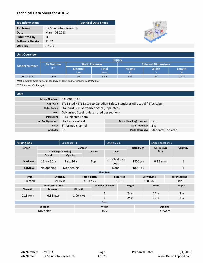
Technical Data Sheet for AH U-2
Job Information Technical Data Sheet
Job Name UK Spindletop Research
Date March 01 2018
Submitted By TE
Software Version 11.52
Unit Tag AHU-2
Unit Overview
Model Number
Supply
Air Volume cfm
Static Pressure External Dimensions
External inWc
Total inWc
Height in
Width in
Length in
CAH004GDAC 1800 2.00 3.89 30* 40* 104**
*Not including base rails, coil connectors, drain connectors and control boxes.
**Total lower deck length.
Unit
Model Number: CAH004GDAC
Approval: ETL Listed / ETL Listed to Canadian Safety Standards (ETL Label / ETLc Label)
Outer Panel: Standard G90 Galvanized Steel (unpainted)
Liner: Galvanized Steel (unless noted per section)
Insulation: R-13 Injected Foam
Unit Configuration: Stacked / vertical Drive (Handling) Location: Left
Base: 8" formed channel Wall Thickness: 2 in
Altitude: 0 ft Parts Warranty: Standard One Year
Mixing Box Component: 1 Length: 20 in Shipping Section: 1
Portion Damper Rated CFM Air Pressure Drop
Quantity Size (length x width) Location Type
Overall Opening
Outside Air 12 in x 36 in 8 in x 26 in Top UltraSeal Low
Leak 1800 cfm 0.12 insWg 1
Return Air No opening No opening None 1800 cfm 1
Filter Data
Type Efficiency Face Velocity Face Area Air Volume Filter Loading
Pleated MERV 8 319 ft/min 5.6 ft² 1800 cfm Side
Air Pressure Drop Number of Filters Height Width Depth Clean Air Mean Air Dirty Air
0.13 inWc 0.56 inWc 1.00 inWc 1 24 in 24 in 2 in
1 24 in 12 in 2 in
Door
Location Width Opening
Drive side 16 in Outward

Technical Data Sheet for AHU-2
Job Number: 9Y1QE3 Page Prepared Date: 3/1/2018 Job Name: UK Spindletop Research 4 of 23 www.DaikinApplied.com
Steam Coil Component: 2 Length: 22 in Shipping Section: 2
Coil Model Total Capacity Number of Coils Number of Rows Fins per Inch Tube Diameter Tube Spacing (Face x Row)
5JA0601B 92449 Btu/hr 1 1 6 0.625 in 1.50 in x 1.299 in
Air Volume Air Temperature Coil Air Pressure Drop
Finned Height Finned Length Face Area Face Velocity Entering Leaving Dry Bulb Dry Bulb
1800 cfm 0.0 °F 47.0 °F 0.08 inWc 21 in 24 in 3.50 ft² 514 ft/min
Fluid Max. Superheat Temp. in Steam Coil Inlet Steam Pressure Condensate Load
2.00 psi 96.00 lb/hr 30.0 °F
Connection [Data Per Coil] Min. Fin Surface Temp. Min. Tube Wall Surface Temp. Type Size Location Material
Threaded 2.000 in Drive side Carbon steel 32.0 °F 32.0 °F
Material Fin Tube Header Case
Aluminum .0095 in Copper .035 in Copper Galvanized track
AHRI 410 Certification
Certified in accordance with the AHRI Forced-Circulation Air-Cooling and Air-Heating Coils Certification Program which is based on AHRI Standard 410 within the Range of Standard Rating Conditions listed in Table 1 of the
Standard. Certified units may be found in the AHRI Directory at www.ahridirectory.org
Door
Location Width Opening
Drive side 12 in Outward
Manual Component Component: 3 Length: 12 in Shipping Section: 3
Pressure Drop
0.00 inWc
Panel
Location Width Opening
Removable panels - in Outward
Technical Data Sheet for AHU-2
Job Number: 9Y1QE3 Page Prepared Date: 3/1/2018 Job Name: UK Spindletop Research 5 of 23 www.DaikinApplied.com
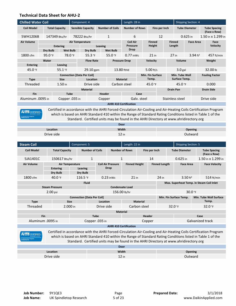
Chilled Water Coil Component: 4 Length: 28 in Shipping Section: 4
Coil Model Total Capacity Sensible Capacity Number of Coils Number of Rows Fins per Inch Tube Diameter Tube Spacing (Face x Row)
5WH1206B 147349 Btu/hr 78222 Btu/hr 1 6 12 0.625 in 1.50 in x 1.299 in
Air Volume Air Temperature Coil Air Pressure
Drop
Finned Height
Finned Length
Face Area Face Velocity Entering Leaving
Dry Bulb Wet Bulb Dry Bulb Wet Bulb
1800 cfm 95.0 °F 78.0 °F 55.3 °F 55.0 °F 0.77 inWc 21 in 27 in 3.94 ft² 457 ft/min
Water Flow Rate Pressure Drop Velocity Volume Weight Entering Leaving
45.0 °F 55.1 °F 29.10 gpm 13.80 ftHd 5.00 ft/s 3.0 gal 32.00 lb
Connection [Data Per Coil] Min. Fin Surface Temp.
Min. Tube Wall Surface Temp.
Fouling Factor Type Size Location Material
Threaded 1.50 in Drive side Carbon steel 45.0 °F 45.0 °F 0.000
Material Drain Pan Drain Side Fin Tube Header Case
Aluminum .0095 in Copper .035 in Copper Galv. steel Stainless steel Drive side
AHRI 410 Certification
Certified in accordance with the AHRI Forced-Circulation Air-Cooling and Air-Heating Coils Certification Program which is based on AHRI Standard 410 within the Range of Standard Rating Conditions listed in Table 1 of the
Standard. Certified units may be found in the AHRI Directory at www.ahridirectory.org
Door
Location Width Opening
Drive side 12 in Outward
Steam Coil Component: 5 Length: 22 in Shipping Section: 5
Coil Model Total Capacity Number of Coils Number of Rows Fins per Inch Tube Diameter Tube Spacing (Face x Row)
5JA1401C 150617 Btu/hr 1 1 14 0.625 in 1.50 in x 1.299 in
Air Volume Air Temperature Coil Air Pressure Drop
Finned Height Finned Length Face Area Face Velocity Entering Leaving Dry Bulb Dry Bulb
1800 cfm 40.0 °F 116.5 °F 0.23 inWc 21 in 24 in 3.50 ft² 514 ft/min
Fluid Max. Superheat Temp. in Steam Coil Inlet Steam Pressure Condensate Load
2.00 psi 156.00 lb/hr 30.0 °F
Connection [Data Per Coil] Min. Fin Surface Temp. Min. Tube Wall Surface Temp. Type Size Location Material
Threaded 2.000 in Drive side Carbon steel 32.0 °F 32.0 °F
Material Fin Tube Header Case
Aluminum .0095 in Copper .035 in Copper Galvanized track
AHRI 410 Certification
Certified in accordance with the AHRI Forced-Circulation Air-Cooling and Air-Heating Coils Certification Program which is based on AHRI Standard 410 within the Range of Standard Rating Conditions listed in Table 1 of the
Standard. Certified units may be found in the AHRI Directory at www.ahridirectory.org
Door
Location Width Opening
Drive side 12 in Outward

Technical Data Sheet for AHU-2
Job Number: 9Y1QE3 Page Prepared Date: 3/1/2018 Job Name: UK Spindletop Research 6 of 23 www.DaikinApplied.com
Access Section Component: 6 Length: 18 in Shipping Section: 6
Air Pressure Drop
0.00 inWc
Panel
Location Width Opening
Removable panels - in Outward
Supply Fan Component: 7 Length: 32 in Shipping Section: 7
Fan Performance
Air Volume Static Pressure Brake Horsepower Speed Outlet Velocity External Total Cabinet Operating Maximum
1800 cfm 2.00 inWc 3.89 inWc 0.13 inWc 2.42 BHP 2338 rpm 2700 rpm 3103 ft/min
Fan Data
Fan Type Blade Type / Class Quantity of Fans Wheel Diameter Number of Blades Discharge Motor Location
Centrifugal DWDI Forward Curved / 2
1 9.50 in N/A Up blast CW To Side of Fan
Motor Data
Power Electrical Supply
Speed Efficiency Enclosure Frame Size Supplier Number of Poles
Lock Rotor Current
Full Load Current
5.0 HP 200/60/3
V/Hz/Phase 1750 rpm Premium ODP 184 T frame Generic 4 122.7 A 15 A
Fan Options
Isolator Type: Rubber in shear
Drive Package Data*
Fan Sheave Motor Sheave Belt Number of Belts Actual Drive S.F. Bearing Type
AK49H AK64H AX29 1 1.10 Standard - L50 (200K)
*Daikin Applied reserves the right to provide a different but equivalent drive package
VFD/Starter/Disconnect Data
Selection Type: VFD Vendor: Daikin Applied
Voltage: 200 V Height x Width x Depth: 11.78 in x 6.63 in x 7.80 in
Mounting: Door Side Enclosure: NEMA 1
VFD Quantity: 1
Door
Location Width Opening
Drive side 20 in Outward
Unit Sound Power (dB)
Type 63 Hz 125 Hz 250 Hz 500 Hz 1000 Hz 2000 Hz 4000 Hz 8000 Hz Radiated: 76 76 65 61 60 55 46 51
Unit Discharge: 86 86 83 82 82 83 80 77
Unit Return: 76 76 67 67 66 67 61 56

Technical Data Sheet for AHU-2
Job Number: 9Y1QE3 Page Prepared Date: 3/1/2018 Job Name: UK Spindletop Research 7 of 23 www.DaikinApplied.com
Shipping Section Details
Section Length in
Weight lb
Corner Weights (lb) Center of Gravity (in) P1 P2 P3 P4 XX YY ZZ
1 20 207 48 48 55 55 11 20 18
2 22 231 60 62 56 54 10 20 18
3 12 142 32 32 39 39 7 20 16
4 28 437 119 132 99 86 12 21 19
5 22 249 65 67 59 57 10 20 18
6 18 111 24 24 32 32 10 20 23
7 32 318 92 73 67 86 15 18 19
Entire Unit
104 Lower level only
1695
n/a
n/a
n/a
n/a
n/a
n/a
n/a
NOTE: Special components aren't included in the corner weights and center of gravity data.
AHRI Certification
Supply fan performance is certified in accordance with the Central Station Air-Handling Unit Certification Program, which is based on AHRI Standard 430.
Notes
Standard
1. As a standalone component, unit meets or exceeds requirements of ASHRAE 90.1 - 2007. The approving authority is responsible for compliance of multi - component building systems.

Job
Nam
e:
Job
Nu
mb
er:
Draw
ing fo
r AH
U-2
UK
Spin
dleto
p R
esearch
9Y1
QE3
8 o
f 23
Page
Pre
pare
d D
ate:
ww
w.D
aikinA
pp
lied.co
m
3/1
/20
18
Drawing for AH U-2

Job
Nam
e:
Job
Nu
mb
er:
Draw
ing fo
r AH
U-2
UK
Spin
dleto
p R
esearch
9Y1
QE3
9 o
f 23
Page
Pre
pare
d D
ate:
ww
w.D
aikinA
pp
lied.co
m
3/1
/20
18

Job
Nam
e:
Job
Nu
mb
er:
Draw
ing fo
r AH
U-2
UK
Spin
dleto
p R
esearch
9Y1
QE3
10
of 2
3
Page
Pre
pare
d D
ate:
ww
w.D
aikinA
pp
lied.co
m
3/1
/20
18

Job
Nam
e:
Job
Nu
mb
er:
Draw
ing fo
r AH
U-2
UK
Spin
dleto
p R
esearch
9Y1
QE3
11
of 2
3
Page
Pre
pare
d D
ate:
ww
w.D
aikinA
pp
lied.co
m
3/1
/20
18

Job
Nam
e:
Job
Nu
mb
er:
Draw
ing fo
r AH
U-2
UK
Spin
dleto
p R
esearch
9Y1
QE3
12
of 2
3
Page
Pre
pare
d D
ate:
ww
w.D
aikinA
pp
lied.co
m
3/1
/20
18

Technical Data Sheet for AHU-3
Job Number: 9Y1QE3 Page Prepared Date: 3/1/2018 Job Name: UK Spindletop Research 13 of 23 www.DaikinApplied.com
Technical Data Sheet for AH U-3
Job Information Technical Data Sheet
Job Name UK Spindletop Research
Date March 01 2018
Submitted By TE
Software Version 11.52
Unit Tag AHU-3
Unit Overview
Model Number
Supply
Air Volume cfm
Static Pressure External Dimensions
External inWc
Total inWc
Height in
Width in
Length in
CAH006GDAC 2400 2.00 3.67 30* 52* 104**
*Not including base rails, coil connectors, drain connectors and control boxes.
**Total lower deck length.
Unit
Model Number: CAH006GDAC
Approval: ETL Listed / ETL Listed to Canadian Safety Standards (ETL Label / ETLc Label)
Outer Panel: Standard G90 Galvanized Steel (unpainted)
Liner: Galvanized Steel (unless noted per section)
Insulation: R-13 Injected Foam
Unit Configuration: Stacked / vertical Drive (Handling) Location: Left
Base: 8" formed channel Wall Thickness: 2 in
Altitude: 0 ft Parts Warranty: Standard One Year
Mixing Box Component: 1 Length: 20 in Shipping Section: 1
Portion Damper Rated CFM Air Pressure Drop
Quantity Size (length x width) Location Type
Overall Opening
Outside Air 12 in x 48 in 8 in x 38 in Top UltraSeal Low
Leak 2400 cfm 0.10 insWg 1
Return Air No opening No opening None 2400 cfm 1
Filter Data
Type Efficiency Face Velocity Face Area Air Volume Filter Loading
Pleated MERV 8 316 ft/min 7.6 ft² 2400 cfm Side
Air Pressure Drop Number of Filters Height Width Depth Clean Air Mean Air Dirty Air
0.12 inWc 0.56 inWc 1.00 inWc 2 24 in 24 in 2 in
Door
Location Width Opening
Drive side 16 in Outward

Technical Data Sheet for AHU-3
Job Number: 9Y1QE3 Page Prepared Date: 3/1/2018 Job Name: UK Spindletop Research 14 of 23 www.DaikinApplied.com
Steam Coil Component: 2 Length: 22 in Shipping Section: 2
Coil Model Total Capacity Number of Coils Number of Rows Fins per Inch Tube Diameter Tube Spacing (Face x Row)
5JA0601B 130377 Btu/hr 1 1 6 0.625 in 1.50 in x 1.299 in
Air Volume Air Temperature Coil Air Pressure Drop
Finned Height Finned Length Face Area Face Velocity Entering Leaving Dry Bulb Dry Bulb
2400 cfm 0.0 °F 49.7 °F 0.06 inWc 21 in 36 in 5.25 ft² 457 ft/min
Fluid Max. Superheat Temp. in Steam Coil Inlet Steam Pressure Condensate Load
2.00 psi 135.00 lb/hr 30.0 °F
Connection [Data Per Coil] Min. Fin Surface Temp. Min. Tube Wall Surface Temp. Type Size Location Material
Threaded 2.000 in Drive side Carbon steel 32.0 °F 32.0 °F
Material Fin Tube Header Case
Aluminum .0095 in Copper .035 in Copper Galvanized track
AHRI 410 Certification
Certified in accordance with the AHRI Forced-Circulation Air-Cooling and Air-Heating Coils Certification Program which is based on AHRI Standard 410 within the Range of Standard Rating Conditions listed in Table 1 of the
Standard. Certified units may be found in the AHRI Directory at www.ahridirectory.org
Door
Location Width Opening
Drive side 12 in Outward
Manual Component Component: 3 Length: 12 in Shipping Section: 3
Pressure Drop
0.00 inWc
Panel
Location Width Opening
Removable panels - in Outward

Technical Data Sheet for AHU-3
Job Number: 9Y1QE3 Page Prepared Date: 3/1/2018 Job Name: UK Spindletop Research 15 of 23 www.DaikinApplied.com
Chilled Water Coil Component: 4 Length: 28 in Shipping Section: 4
Coil Model Total Capacity Sensible Capacity Number of Coils Number of Rows Fins per Inch Tube Diameter Tube Spacing (Face x Row)
5WL1106B 194137 Btu/hr 103222 Btu/hr 1 6 11 0.625 in 1.50 in x 1.299 in
Air Volume Air Temperature Coil Air Pressure
Drop
Finned Height
Finned Length
Face Area Face Velocity Entering Leaving
Dry Bulb Wet Bulb Dry Bulb Wet Bulb
2400 cfm 95.0 °F 78.0 °F 55.7 °F 55.3 °F 0.64 inWc 21 in 39 in 5.69 ft² 422 ft/min
Water Flow Rate Pressure Drop Velocity Volume Weight Entering Leaving
45.0 °F 55.0 °F 38.80 gpm 8.80 ftHd 4.40 ft/s 5.0 gal 44.00 lb
Connection [Data Per Coil] Min. Fin Surface Temp.
Min. Tube Wall Surface Temp.
Fouling Factor Type Size Location Material
Threaded 2.00 in Drive side Carbon steel 45.0 °F 45.0 °F 0.000
Material Drain Pan Drain Side Fin Tube Header Case
Aluminum .0095 in Copper .035 in Copper Galv. steel Stainless steel Drive side
AHRI 410 Certification
Certified in accordance with the AHRI Forced-Circulation Air-Cooling and Air-Heating Coils Certification Program which is based on AHRI Standard 410 within the Range of Standard Rating Conditions listed in Table 1 of the
Standard. Certified units may be found in the AHRI Directory at www.ahridirectory.org
Door
Location Width Opening
Drive side 12 in Outward
Steam Coil Component: 5 Length: 22 in Shipping Section: 5
Coil Model Total Capacity Number of Coils Number of Rows Fins per Inch Tube Diameter Tube Spacing (Face x Row)
5JA1301C 200258 Btu/hr 1 1 13 0.625 in 1.50 in x 1.299 in
Air Volume Air Temperature Coil Air Pressure Drop
Finned Height Finned Length Face Area Face Velocity Entering Leaving Dry Bulb Dry Bulb
2400 cfm 40.0 °F 116.3 °F 0.18 inWc 21 in 36 in 5.25 ft² 457 ft/min
Fluid Max. Superheat Temp. in Steam Coil Inlet Steam Pressure Condensate Load
2.00 psi 207.00 lb/hr 30.0 °F
Connection [Data Per Coil] Min. Fin Surface Temp. Min. Tube Wall Surface Temp. Type Size Location Material
Threaded 2.000 in Drive side Carbon steel 32.0 °F 32.0 °F
Material Fin Tube Header Case
Aluminum .0095 in Copper .035 in Copper Galvanized track
AHRI 410 Certification
Certified in accordance with the AHRI Forced-Circulation Air-Cooling and Air-Heating Coils Certification Program which is based on AHRI Standard 410 within the Range of Standard Rating Conditions listed in Table 1 of the
Standard. Certified units may be found in the AHRI Directory at www.ahridirectory.org
Door
Location Width Opening
Drive side 12 in Outward

Technical Data Sheet for AHU-3
Job Number: 9Y1QE3 Page Prepared Date: 3/1/2018 Job Name: UK Spindletop Research 16 of 23 www.DaikinApplied.com
Access Section Component: 6 Length: 18 in Shipping Section: 6
Air Pressure Drop
0.00 inWc
Panel
Location Width Opening
Removable panels - in Outward
Supply Fan Component: 7 Length: 36 in Shipping Section: 7
Fan Performance
Air Volume Static Pressure Brake Horsepower Speed Outlet Velocity External Total Cabinet Operating Maximum
2400 cfm 2.00 inWc 3.67 inWc 0.13 inWc 2.47 BHP 1920 rpm 2518 rpm 2286 ft/min
Fan Data
Fan Type Blade Type / Class Quantity of Fans Wheel Diameter Number of Blades Discharge Motor Location
Centrifugal DWDI Forward Curved / 2
1 10.62 in N/A Up blast CW To Side of Fan
Motor Data
Power Electrical Supply
Speed Efficiency Enclosure Frame Size Supplier Number of Poles
Lock Rotor Current
Full Load Current
5.0 HP 200/60/3
V/Hz/Phase 1750 rpm Premium ODP 184 T frame Generic 4 122.7 A 15 A
Fan Options
Isolator Type: Spring
Drive Package Data*
Fan Sheave Motor Sheave Belt Number of Belts Actual Drive S.F. Bearing Type
AK59H AK64H A31 1 1.18 Standard - L50 (200K)
*Daikin Applied reserves the right to provide a different but equivalent drive package
VFD/Starter/Disconnect Data
Selection Type: VFD Vendor: Daikin Applied
Voltage: 200 V Height x Width x Depth: 11.78 in x 6.63 in x 7.80 in
Mounting: Door Side Enclosure: NEMA 1
VFD Quantity: 1
Door
Location Width Opening
Drive side 24 in Outward
Unit Sound Power (dB)
Type 63 Hz 125 Hz 250 Hz 500 Hz 1000 Hz 2000 Hz 4000 Hz 8000 Hz Radiated: 73 76 63 59 58 52 46 51
Unit Discharge: 83 86 81 80 80 80 77 74
Unit Return: 73 76 65 65 64 64 58 53

Technical Data Sheet for AHU-3
Job Number: 9Y1QE3 Page Prepared Date: 3/1/2018 Job Name: UK Spindletop Research 17 of 23 www.DaikinApplied.com
Shipping Section Details
Section Length in
Weight lb
Corner Weights (lb) Center of Gravity (in) P1 P2 P3 P4 XX YY ZZ
1 20 247 57 57 66 66 11 26 19
2 22 272 71 73 65 63 10 26 18
3 12 165 37 37 46 46 7 26 16
4 28 537 150 163 119 105 12 27 19
5 22 295 78 80 70 68 10 26 18
6 18 130 28 28 37 37 10 26 23
7 36 451 132 108 93 117 17 23 19
Entire Unit
104 Lower level only
2097
n/a
n/a
n/a
n/a
n/a
n/a
n/a
NOTE: Special components aren't included in the corner weights and center of gravity data.
AHRI Certification
Supply fan performance is certified in accordance with the Central Station Air-Handling Unit Certification Program, which is based on AHRI Standard 430.
Notes
Standard
1. As a standalone component, unit meets or exceeds requirements of ASHRAE 90.1 - 2007. The approving authority is responsible for compliance of multi - component building systems.

Job
Nam
e:
Job
Nu
mb
er:
Draw
ing fo
r AH
U-3
UK
Spin
dleto
p R
esearch
9Y1
QE3
18
of 2
3
Page
Pre
pare
d D
ate:
ww
w.D
aikinA
pp
lied.co
m
3/1
/20
18
Drawing for AH U-3

Job
Nam
e:
Job
Nu
mb
er:
Draw
ing fo
r AH
U-3
UK
Spin
dleto
p R
esearch
9Y1
QE3
19
of 2
3
Page
Pre
pare
d D
ate:
ww
w.D
aikinA
pp
lied.co
m
3/1
/20
18

Job
Nam
e:
Job
Nu
mb
er:
Draw
ing fo
r AH
U-3
UK
Spin
dleto
p R
esearch
9Y1
QE3
20
of 2
3
Page
Pre
pare
d D
ate:
ww
w.D
aikinA
pp
lied.co
m
3/1
/20
18

Job
Nam
e:
Job
Nu
mb
er:
Draw
ing fo
r AH
U-3
UK
Spin
dleto
p R
esearch
9Y1
QE3
21
of 2
3
Page
Pre
pare
d D
ate:
ww
w.D
aikinA
pp
lied.co
m
3/1
/20
18

Job
Nam
e:
Job
Nu
mb
er:
Draw
ing fo
r AH
U-3
UK
Spin
dleto
p R
esearch
9Y1
QE3
22
of 2
3
Page
Pre
pare
d D
ate:
ww
w.D
aikinA
pp
lied.co
m
3/1
/20
18
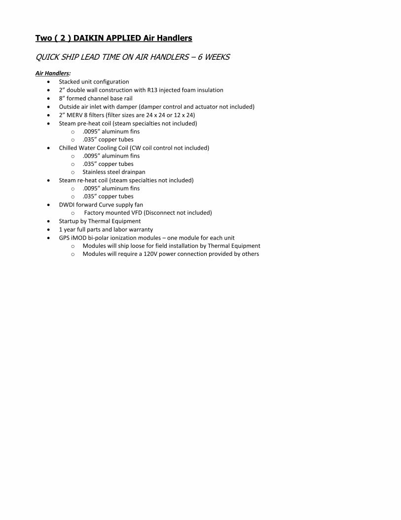
Two ( 2 ) DAIKIN APPLIED Air Handlers QUICK SHIP LEAD TIME ON AIR HANDLERS – 6 WEEKS Air Handlers:
Stacked unit configuration
2” double wall construction with R13 injected foam insulation
8” formed channel base rail
Outside air inlet with damper (damper control and actuator not included)
2” MERV 8 filters (filter sizes are 24 x 24 or 12 x 24)
Steam pre-heat coil (steam specialties not included) o .0095” aluminum fins o .035” copper tubes
Chilled Water Cooling Coil (CW coil control not included) o .0095” aluminum fins o .035” copper tubes o Stainless steel drainpan
Steam re-heat coil (steam specialties not included) o .0095” aluminum fins o .035” copper tubes
DWDI forward Curve supply fan o Factory mounted VFD (Disconnect not included)
Startup by Thermal Equipment
1 year full parts and labor warranty
GPS iMOD bi-polar ionization modules – one module for each unit o Modules will ship loose for field installation by Thermal Equipment o Modules will require a 120V power connection provided by others