ATTENTION! READ INSTRUCTIONS CAREFULLY BEFORE...
8
1 Wireless Wall Thermostat (TS-2R) Wireless Wall Switch (WS-2R) Wireless Wall Timer (30/60/120 Minutes) (WT-2R) Wireless On/Off Remote (SR-2R) Wireless On/Off Remote with Thermostat (THR-2R) RPK3E PARTS LIST REV: RPK3E-0410 Last Printed 4/28/2010 8:33 AM RPK3E - Remote Ready “EASY” Control General Assembly, Installation, and Operation Instructions for use with Natural Gas Burners; F, FX, CS, CXF, TNA or Propane Gas Burners: FA, FAX, CA, CXFA, TNA/LP REQUIRED TOOLS AND MATERIALS Adjustable Wrench, Pipe Wrench, Flat Head Screwdriver, Phillips Screwdriver, Pipe Sealing compound (Only required if fittings not already prepared with pre-wrapped Teflon thread tape). 1. Air Mixer for LP Gas Burner Inlet Assembly (MA2) 2. Burner Orifice #53,49 and 45 (01-XX) 3. Internally Tapped 3/8 Flared x 3/8 MIP Elbow (A2T) 4a. Pilot Support Bracket for F & TNA burners (PB-1) 4b. Pilot Support Bracket for CS & CXF burners (PB-2) 4c. Thermocouple Heat shield for left side gas supply (PB-4) 5. 10-32 x 3/8 bolts (qty. 3) 6. 10-32 Hex nut (qty 1) 2 8 (Green mark indicates Natural Gas, Red indicates Propane Gas) 10 1 3 4B 4A 11 13 ATTENTION! READ INSTRUCTIONS CAREFULLY BEFORE ASSEMBLY INSTALLER : LEAVE THIS MANUAL WITH THE APPLIANCE ● CONSUMER: RETAIN THIS MANUAL FOR FUTURE REFERENCE What sets Rasmussen Safety Pilot Kits apart from those of other manufacturers, aside from quality, is the ease and affordability with which our valve can be upgraded from manual operation to one of several remote control devices! WIRELESS REMOTE OPTIONS (each sold separately ) HI/LO DC Motor Drive (STV-VMD) Variable Flame Height Remote Control Transmitter (STR-RMD) Battery Pack/Receiver (BPR3) “RE” “Variable Flame Height” Remote Control Upgrade Kit (RE-UP1) Kit to upgrade from “ME” or “SE” to “RE” functionality. Includes: DC Motor Drive, Receiver, Transmitter and batteries. 12 6 7 UPGRADE OPTION 7. Valve Plug ( used when replacing, servicing or upgrading Motor Drive) (VALVE PLUG EASY). 8. Valve Knob Extender (STV-KE2) 9. “EASY” Safety Valve (STV-10) & Heat shield (HS-ST1) 10. Pilot Thermocouple Assembly (J95R -NG or -LP) 11. 10” flex Connector (SSCB-10) 12. Remote Receiver (BPR3) 13. Ceramic Log House (RH2) (Sold Separately) 9 4c 5 (Thermocouple Lead Fitting) Owner’s Manual ® 12028 E. PHILADELPHIA ST. WHITTIER, CA 90601 U.S.A. www.rasmussen.biz THE GAS LOG COMPANY Report # 10-38
Transcript of ATTENTION! READ INSTRUCTIONS CAREFULLY BEFORE...

1
Wireless Wall Thermostat (TS-2R)
Wireless Wall Switch
(WS-2R)
Wireless Wall Timer (30/60/120 Minutes)
(WT-2R)
Wireless On/Off Remote (SR-2R)
Wireless On/Off Remote with Thermostat (THR-2R)
RPK3E PARTS LIST
REV: RPK3E-0410 Last Printed 4/28/2010 8:33 AM
RPK3E - Remote Ready “EASY” Control General Assembly, Installation, and Operation Instructions for use with Natural Gas Burners;
F, FX, CS, CXF, TNA or Propane Gas Burners: FA, FAX, CA, CXFA, TNA/LP
REQUIRED TOOLS AND MATERIALS
Adjustable Wrench, Pipe Wrench, Flat Head Screwdriver, Phillips Screwdriver, Pipe Sealing compound (Only required if fittings not already prepared with pre-wrapped Teflon thread tape).
1. Air Mixer for LP Gas Burner Inlet Assembly (MA2)
2. Burner Orifice #53,49 and 45 (01-XX) 3. Internally Tapped 3/8 Flared x 3/8 MIP Elbow (A2T) 4a. Pilot Support Bracket for F & TNA burners (PB-1) 4b. Pilot Support Bracket for CS & CXF burners (PB-2) 4c. Thermocouple Heat shield for left side gas supply (PB-4) 5. 10-32 x 3/8 bolts (qty. 3) 6. 10-32 Hex nut (qty 1)
2 8
(Green mark indicates Natural Gas, Red indicates Propane Gas)
10
1 3 4B 4A
11
13
ATTENTION! READ INSTRUCTIONS CAREFULLY BEFORE ASSEMBLY INSTALLER: LEAVE THIS MANUAL WITH THE APPLIANCE ● CONSUMER: RETAIN THIS MANUAL FOR FUTURE REFERENCE
What sets Rasmussen Safety Pilot Kits apart from those of other manufacturers, aside from quality, is the ease and affordability with which our valve can be upgraded from manual operation to one of several remote control devices!
WIRELESS REMOTE OPTIONS (each sold separately)
HI/LO DC Motor Drive (STV-VMD)
Variable Flame Height Remote Control Transmitter (STR-RMD)
Battery Pack/Receiver (BPR3)
“RE” “Variable Flame Height” Remote Control Upgrade Kit (RE-UP1)
Kit to upgrade from “ME” or “SE” to “RE” functionality. Includes: DC Motor Drive, Receiver, Transmitter
and batteries.
12
6 7
UPGRADE OPTION
7. Valve Plug ( used when replacing, servicing or upgrading Motor Drive) (VALVE PLUG EASY). 8. Valve Knob Extender (STV-KE2) 9. “EASY” Safety Valve (STV-10) & Heat shield (HS-ST1) 10. Pilot Thermocouple Assembly (J95R -NG or -LP) 11. 10” flex Connector (SSCB-10) 12. Remote Receiver (BPR3) 13. Ceramic Log House (RH2) (Sold Separately)
9
4c
5
(Thermocouple Lead Fitting)
Owner’s Manual
® 12028 E. PHILADELPHIA ST.
WHITTIER, CA 90601 U.S.A. www.rasmussen.biz THE GAS LOG COMPANY
Report # 10-38
2
With the PILOT THERMOCOUPLE ASSEMBLY (Figure 2A) attached to the PILOT SUPPORT BRACKET (Figure 2B), insert the 10-32 BOLTS (Figure 2C) through the pre-drilled holes of the Pilot Support Bracket and into the threaded holes of the Pilot Thermocouple Assembly (Figure 2A). Tighten with flathead screwdriver.
STEP TWO: ATTACH PILOT (Figures 2 thru 5) NOTE: The following pilot attachment instructions apply to each burner model shown in Figures 2 thru 5.
FIGURE 2 (F, FX, FA and FAX Burners)
B) Pilot Support Bracket
E) 10-32 nut
C) 10-32 bolts
F) Burner Pipe
FIGURE 3 CS/CA Burners
10-32 bolts
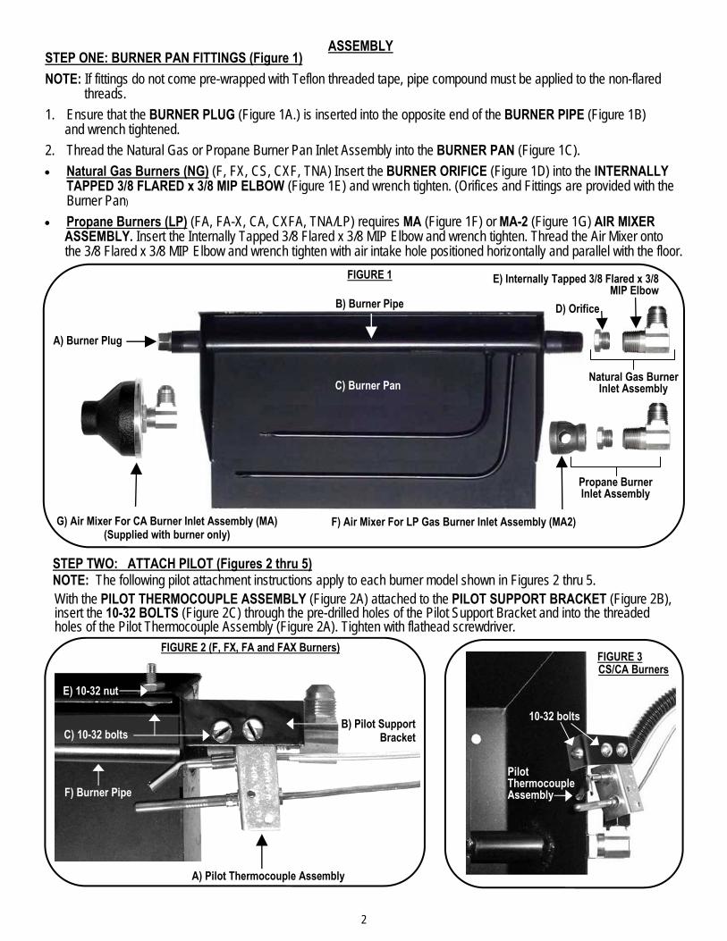
ASSEMBLY STEP ONE: BURNER PAN FITTINGS (Figure 1)
NOTE: If fittings do not come pre-wrapped with Teflon threaded tape, pipe compound must be applied to the non-flared threads.
1. Ensure that the BURNER PLUG (Figure 1A.) is inserted into the opposite end of the BURNER PIPE (Figure 1B) and wrench tightened.
2. Thread the Natural Gas or Propane Burner Pan Inlet Assembly into the BURNER PAN (Figure 1C).
• Natural Gas Burners (NG) (F, FX, CS, CXF, TNA) Insert the BURNER ORIFICE (Figure 1D) into the INTERNALLY TAPPED 3/8 FLARED x 3/8 MIP ELBOW (Figure 1E) and wrench tighten. (Orifices and Fittings are provided with the Burner Pan)
• Propane Burners (LP) (FA, FA-X, CA, CXFA, TNA/LP) requires MA (Figure 1F) or MA-2 (Figure 1G) AIR MIXER ASSEMBLY. Insert the Internally Tapped 3/8 Flared x 3/8 MIP Elbow and wrench tighten. Thread the Air Mixer onto the 3/8 Flared x 3/8 MIP Elbow and wrench tighten with air intake hole positioned horizontally and parallel with the floor.
A) Burner Plug
B) Burner Pipe
C) Burner Pan
E) Internally Tapped 3/8 Flared x 3/8 MIP Elbow
FIGURE 1
G) Air Mixer For CA Burner Inlet Assembly (MA) (Supplied with burner only)
F) Air Mixer For LP Gas Burner Inlet Assembly (MA2)
D) Orifice
Propane Burner Inlet Assembly
Natural Gas Burner Inlet Assembly
A) Pilot Thermocouple Assembly
Pilot Thermocouple Assembly

3
FIGURE 4 (CXF AND CXFA Burners
Pilot Thermocouple Assembly
10-32 bolts
FIGURE 5 (TNA / TNA-LP Burners)
10-32 nuts & bolts
Pilot Thermocouple Assembly
A) 10” FLEX CONNECTOR
B) VALVE OUTPUT 3/8 FLARED FITTING
C) BURNER INPUT 3/8 FLARED x 3/8
MIP ELBOW
VALVE INPUT
VALVE OUTPUT 3/8 FLARED FITTING WITH
10” FLEX CONNECTOR ATTACHED
VALVE INPUT 3/8 FLARED FITTING (Attach to Gas Supply)
PILOT INPUT
FIGURE 6
Connect 10” FLEX CONNECTOR (Figure 6A) between the flared ends of the VALVE OUTPUT 3/8 FLARED FITTING (Figure 6B) and the BURNER INPUT 3/8 FLARED 3/8 x MIP ELBOW (Figure C). Bend the 10” Flex Connector to the optimum Valve position (forward and to the side of the Burner pan, low to the floor).
STEP THREE: CONNECT BURNER AND PILOT GAS SUPPLY

4
FIGURE 7 10-32 nut
10-32 bolt
10-32 bolts
Thermocouple Heat Shield
(PB4)
LEFT SIDE GAS SUPPLY CONNECTION
Attach the Pilot Support Bracket (PB-1) to the left side of the burner pan using a 10-32 nut and bolt (Figure 7A), then place the Pilot Thermocouple Assembly over the bracket aligning the two screw holes (Figure 7b). Place the Thermocouple Heat Shield over the Thermocouple Assembly and bolt onto the Pilot Support Bracket using the supplied 10-32 nuts and bolts (Figure 7C).
A)
Pilot Support Bracket (PB-1)
B)
C)
Pilot Thermocouple Assembly
Burner Plug
Gas Supply Pipe
Pilot Support Bracket bolted onto burner pan
5
Internally Tapped 3/8 Flared x 3/8 MIP Elbow
Burner Plug
Burner Pipe
Air Mixer For LP Gas Burner Inlet Assembly
10” Flex Connector Burner Pan
Pilot Thermocouple Assembly
Burners
B) “EASY” Safety Valve
Heat Shield A)
C) Remote Receiver
E.
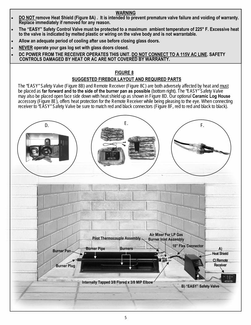
The “EASY” Safety Valve (Figure 8B) and Remote Receiver (Figure 8C) are both adversely affected by heat and must be placed as far forward and to the side of the burner pan as possible (bottom right). The “EASY” Safety Valve may also be placed open face side down with heat shield up as shown in Figure 8D. Our optional Ceramic Log House accessory (Figure 8E), offers heat protection for the Remote Receiver while being pleasing to the eye. When connecting receiver to “EASY” Safety Valve be sure to match red and black connectors (Figure 8F, red to red and black to black).
WARNING
• DO NOT remove Heat Shield (Figure 8A) . It is intended to prevent premature valve failure and voiding of warranty. Replace immediately if removed for any reason.
• The “EASY” Safety Control Valve must be protected to a maximum ambient temperature of 225° F. Excessive heat to the valve is indicated by melted plastic or wiring on the valve body and is not warrantable.
• Allow an adequate period of cooling after use before closing glass doors.
• NEVER operate your gas log set with glass doors closed.
• DC POWER FROM THE RECEIVER OPERATES THIS UNIT. DO NOT CONNECT TO A 115V AC LINE. SAFETY CONTROLS DAMAGED BY HEAT OR AC ARE NOT COVERED BY WARRANTY.
SUGGESTED FIREBOX LAYOUT AND REQUIRED PARTS FIGURE 8
D. F.
6
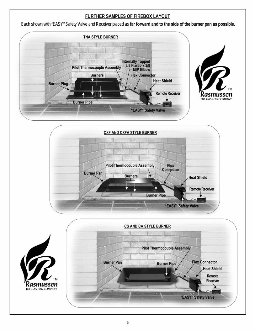
FURTHER SAMPLES OF FIREBOX LAYOUT
TNA STYLE BURNER
CXF AND CXFA STYLE BURNER
CS AND CA STYLE BURNER
Burners
Burner Plug
Burner Pipe
Flex Connector Heat Shield
Internally Tapped 3/8 Flared x 3/8
MIP Elbow
Burners
Burner Pipe
Burner Pan
Pilot Thermocouple Assembly Flex Connector
Heat Shield
Burner Pipe Burner Pan
Pilot Thermocouple Assembly
Flex Connector Heat Shield
Each shown with “EASY” Safety Valve and Receiver placed as far forward and to the side of the burner pan as possible.
“EASY” Safety Valve
Remote Receiver
“EASY” Safety Valve
Remote Receiver
Pilot Thermocouple Assembly
“EASY” Safety Valve
Remote Receiver
7
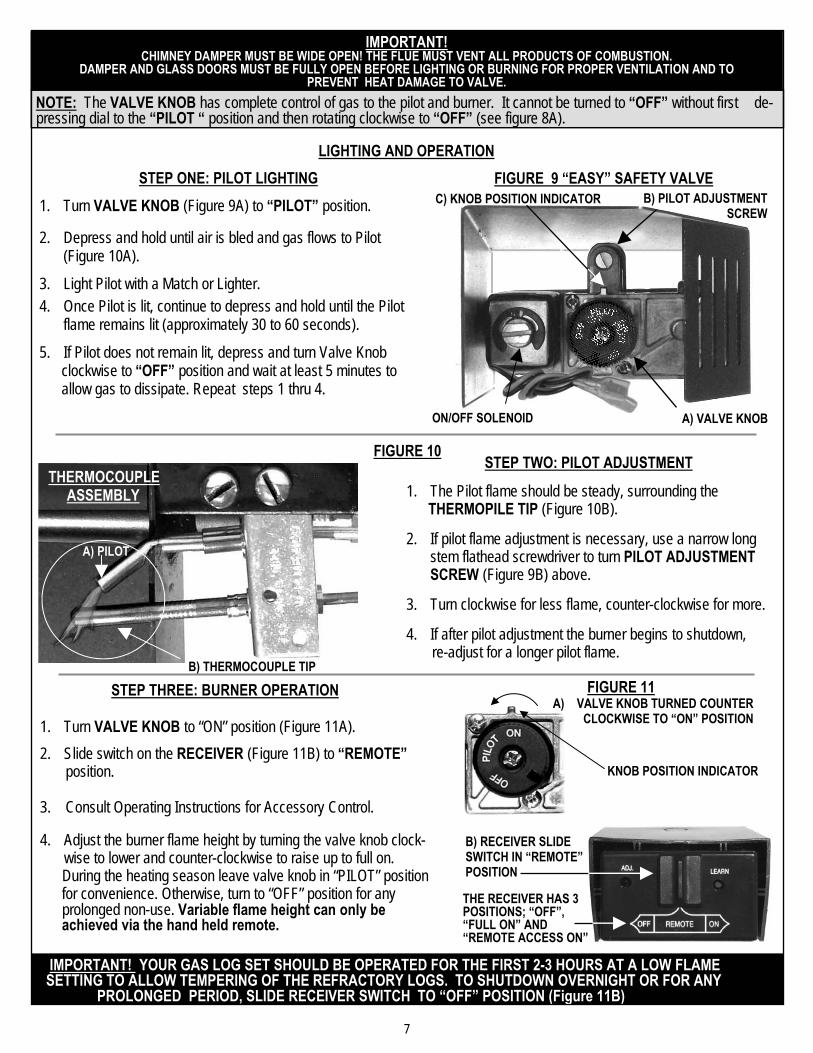
1. Turn VALVE KNOB to “ON” position (Figure 11A).
2. Slide switch on the RECEIVER (Figure 11B) to “REMOTE” position. 3. Consult Operating Instructions for Accessory Control. 4. Adjust the burner flame height by turning the valve knob clock-
wise to lower and counter-clockwise to raise up to full on. During the heating season leave valve knob in “PILOT” position for convenience. Otherwise, turn to “OFF” position for any prolonged non-use. Variable flame height can only be achieved via the hand held remote.
ON/OFF SOLENOID
B) PILOT ADJUSTMENT SCREW
A) VALVE KNOB
C) KNOB POSITION INDICATOR
LIGHTING AND OPERATION
IMPORTANT! YOUR GAS LOG SET SHOULD BE OPERATED FOR THE FIRST 2-3 HOURS AT A LOW FLAME SETTING TO ALLOW TEMPERING OF THE REFRACTORY LOGS. TO SHUTDOWN OVERNIGHT OR FOR ANY PROLONGED PERIOD, SLIDE RECEIVER SWITCH TO “OFF” POSITION (Figure 11B)
FIGURE 11 STEP THREE: BURNER OPERATION
1. The Pilot flame should be steady, surrounding the THERMOPILE TIP (Figure 10B). 2. If pilot flame adjustment is necessary, use a narrow long
stem flathead screwdriver to turn PILOT ADJUSTMENT SCREW (Figure 9B) above.
3. Turn clockwise for less flame, counter-clockwise for more. 4. If after pilot adjustment the burner begins to shutdown, re-adjust for a longer pilot flame.
STEP TWO: PILOT ADJUSTMENT THERMOCOUPLE ASSEMBLY
FIGURE 10
A) PILOT
B) THERMOCOUPLE TIP
NOTE: The VALVE KNOB has complete control of gas to the pilot and burner. It cannot be turned to “OFF” without first de-pressing dial to the “PILOT “ position and then rotating clockwise to “OFF” (see figure 8A).
IMPORTANT! CHIMNEY DAMPER MUST BE WIDE OPEN! THE FLUE MUST VENT ALL PRODUCTS OF COMBUSTION.
DAMPER AND GLASS DOORS MUST BE FULLY OPEN BEFORE LIGHTING OR BURNING FOR PROPER VENTILATION AND TO PREVENT HEAT DAMAGE TO VALVE.
FIGURE 9 “EASY” SAFETY VALVE STEP ONE: PILOT LIGHTING 1. Turn VALVE KNOB (Figure 9A) to “PILOT” position.
2. Depress and hold until air is bled and gas flows to Pilot (Figure 10A).
3. Light Pilot with a Match or Lighter. 4. Once Pilot is lit, continue to depress and hold until the Pilot
flame remains lit (approximately 30 to 60 seconds).
5. If Pilot does not remain lit, depress and turn Valve Knob clockwise to “OFF” position and wait at least 5 minutes to allow gas to dissipate. Repeat steps 1 thru 4.
A) VALVE KNOB TURNED COUNTER CLOCKWISE TO “ON” POSITION
B) RECEIVER SLIDE SWITCH IN “REMOTE” POSITION
KNOB POSITION INDICATOR
THE RECEIVER HAS 3 POSITIONS; “OFF”, “FULL ON” AND “REMOTE ACCESS ON”

8
“RPK3E / SE” Troubleshooting Guide
Complaint: Pilot flame fails to light / Pilot burner releases no gas.
Is the gas supply turned on? Is the gas tank empty?
Comment: Hold gas valve knob in until all the air has dissipated.
A) Volcanic rock may be impeding full depression of the valve knob. B) Gas valve knob should be depressed for a full 30 to 60 seconds.
Complaint: Pilot lights, but fails to remain lit after releasing valve knob.
Is the pilot adjustment correct? (see figure 10 page 7)
A) If pilot flame is low, turn pilot adjustment screw counter clockwise for a longer pilot flame. B) If set to high, turn valve adjustment screw clockwise to lower pilot flame.
Comment: The ideal pilot flame characteristic is steady and soft blue surrounding 1/8 inch of the thermocouple. (See “Pilot Flame Adjustment”, figure 10 page 7 in the RPK3E (-SE) (-N/P) instruction manual.
Is thermocouple lead making electrical contact with the valve body? (see page 1, number 10)
A) The thermocouple lead fitting might be over tightened (damaging the thermocouple lead) or under tightened.
B) The correct torque is achieved by hand tightening the thermocouple lead fitting, then one half turn with a 3/8” wrench.
Is gas pressure too low?
Comment: The minimum required W.C. pressures are: 5” W.C. natural gas and 11” W.C. for propane gas.
Complaint: My remote will not work
Is the gas valve knob in the on position? The “SE” model requires a Variable Remote Transmitter Device. (Call your supplier) Is the receiver button in the remote position? Try re-installing the batteries in the receiver (connected to valve) as well as the transmitter (remote) Press the learn button once to set frequency. (see remote receiver instructions page 1, or RPK3E (-SE) (-N/P) instructions page 7, figure 11)
Comment: If you have pressed the learn button too many times it can be reset by holding the learn button down for ten seconds, then press the learn button once to re-learn the frequency.
Note: When installing more than one unit into the same home; 1) Install batteries into one transmitter and receiver at a time. 2) Once the unit is operating correctly turn receiver to “OFF” position and continue with next installation. 3) Only after each unit has been programmed can they all be turned to the “ON” position and operated.
Note: Two wireless remote devices cannot operate the same receiver, however they may be interchanged by re-learning the radio frequency.
Complaint: Why is there a beeping sound coming from the fireplace?
Is the receiver properly located? (See “Firebox layout” pg. 5 of the RPK3E (-SE) (-N/P) instruction manual.) Is the receiver positioned where ambient temperatures do not exceed 130 F°? Do batteries need replacing? (check and replace batteries annually.)
Complaint: Why is my burner turning on by itself?
Comment: The system can be affected by radio frequencies (RF) within a 20’ range using non-directional signals, therefore unknown ultra sound sources are capable of turning the burner on and off. When shutting down for the night, vacation or a prolonged period place receiver in the off position.
Note: In the event of failure in the field, the “EASY Safety Pilot Kit” may be operated manually. A “Valve Plug Easy” is included in every RPK3E (-SE) (-N/P) (page 1, number 7). Follow instructions carefully:
1) Place gas valve knob in the off position (page 7 RPK3E (-SE) (-N/P) instructions) 2) Remove motor drive and replace with valve plug.
Call your supplier for the information needed to repair your remote. When sending to your supplier for testing pack these items : Motor Drive, Receiver, and Transmitter.