Attachment 7.3 SA Power Networks: Distribution Annual ... - 7.3 PUBLIC - SAPN... · SA Power...
404
Attachment 7.3 SA Power Networks: Distribution Annual Planning Report October 2014
Transcript of Attachment 7.3 SA Power Networks: Distribution Annual ... - 7.3 PUBLIC - SAPN... · SA Power...

Attachment 7.3
SA Power Networks: Distribution Annual Planning Report
October 2014

Distribution Annual Planning Report
Version 1.0 Page 1
SA Power Networks
Distribution Annual Planning Report
www.sapowernetworks.com.au
Version 1.0
30 October 2014

Distribution Annual Planning Report
Version 1.1 Page ii
Disclaimer
The purpose of this document is to provide information about actual and forecast constraints on SA Power Networks’ Distribution Network and details of these constraints, where they are expected to arise within the forward planning period.
This document is not intended to be used for other purposes, such as making decisions to invest in generation, transmission or distribution capacity.
Whilst care was taken in the preparation of the information in this document, and it is provided in good faith, SA Power Networks accepts no responsibility or liability for any loss or damage that may be incurred by any person acting in reliance on this information or assumptions drawn from it.
This Distribution Annual Planning Report (DAPR) has been prepared in accordance with the National Electricity Rules (NER), in particular Schedule 5.8.
This document contains certain predictions, estimates and statements that reflect various assumptions concerning, amongst other things, economic growth and load growth forecasts that, by their nature, may or may not prove to be correct. This document also contains statements about SA Power Networks’ plans. These plans may change from time to time without notice and should therefore be confirmed with SA Power Networks before any action is taken based on this document.
SA Power Networks advises that anyone proposing to use the information in this document should verify its reliability, accuracy and completeness before committing to any course of action. SA Power Networks makes no warranties or representations as to the document’s reliability, accuracy and completeness and SA Power Networks specifically disclaims any liability or responsibility for any errors or omissions.

Distribution Annual Planning Report
Version 1.1 Page iii
Executive Summary
SA Power Networks is the licensed electricity distributor for South Australia. This annual report is SA Power Networks' assessment of the distribution system's capacity to meet forecasted demand over the forward planning period and possible plans for augmentation of the distribution network. It is based on the information and estimates available at this time and is subject to annual review. The Distribution Annual Planning Report (DAPR) replaces the Electricity System Development Plan (ESDP) published prior to 2013.
This report includes an overview of SA Power Networks’ system planning methodology, 13 regional development plans and specific plans for metropolitan 66kV lines. Where relevant, details of system constraints and the corresponding proposed projects are included in these development plans.
Only those projects that have the most significant customer impact have been included in detail. This generally includes substation, voltage support, power factor correction and 66kV line capacity projects with an estimated value in excess of $5 million and asset refurbishment or replacement projects with an estimated value in excess of $2 million.
The planning criteria used to develop distribution capacity plans are designed to meet SA Power Networks’ reliability obligations and maintain historical levels of network performance.
Those network augmentations planned for completion in 2014/15 and which have financial commitment at the time of publication of this document are considered to be complete for the purposes of this report.
Future (non-committed) load increases due to large customer connections are not included in the report. Network augmentations required for such projects will be managed in accordance with the NER and assessed on a case by case basis.

Distribution Annual Planning Report
Version 1.1 Page iv
Contacts
It is always prudent to consult SA Power Networks for more information regarding the content of this report. Please telephone the Network Managers for the relevant areas, prior to committing significant resources to a project: Network Manager North Keith Boyce 08 8282 1540 Network Manager South Mike Magin 08 8404 4627

Distribution Annual Planning Report
Version 1.1 Page v
Table of Contents
Disclaimer............................................................................................................................................ 2
Executive Summary ............................................................................................................................. 3
Contacts .............................................................................................................................................. 4
Table of Contents ................................................................................................................................ 5
Glossary of Terms................................................................................................................................ 9
Compliance Statement.......................................................................................................................... 13
1. Introduction and Network Overview .............................................................................................. 1
1.1 Purpose of this Report .............................................................................................................. 1
1.2 Description of SA Power Networks' Distribution Network ....................................................... 2
2. Planning Standards and Procedures ............................................................................................... 4
2.1 Load Forecast Methodology ..................................................................................................... 4
2.2 Network Planning Criteria......................................................................................................... 5
2.3 Summary of Planning Criteria for the Distribution Network .................................................... 5
2.4 Joint Planning ............................................................................................................................ 9
3. Network Performance................................................................................................................... 10
3.1 Measures and standards of Reliability .................................................................................... 10
3.2 Quality of supply standards .................................................................................................... 11
3.3 SA Power Networks’ performance in 2013/14 ....................................................................... 12
3.3.1 Reliability Performance ................................................................................................. 12
3.3.2 GSL Performance ........................................................................................................... 14
3.3.3 Quality of Supply Performance ..................................................................................... 15
3.4 SA Power Networks’ Reliability and Quality of Supply Monitoring ........................................ 17
3.5 Annual AER submission on Service Target Performance Incentive Scheme (STPIS) .............. 17
3.5.1 Outline of Information Provided to AER on the STPIS .................................................. 17
3.5.2 2013/14 STPIS Feeder Category Performance .............................................................. 18
3.5.3 Forecasts for Performance against STPIS ...................................................................... 18
4. Asset Management ....................................................................................................................... 19
4.1 Introduction ............................................................................................................................ 19
4.2 Asset Management Strategy................................................................................................... 19
4.3 Committed Asset Refurbishment or Replacement Projects ................................................... 21
5. Demand Management Activities .................................................................................................. 22
5.1 SA Power Networks Demand Management activities ............................................................ 22
5.2 Non-network options considered in the past year ................................................................. 22
5.3 Actions taken to promote non-network proposals ................................................................ 23
5.4 Plans for future Demand Management and embedded generation ...................................... 23
6. Metering and information technology systems ............................................................................ 24
Distribution Annual Planning Report
Version 1.1 Page vi
7. Metropolitan 66kV Sub-transmission Network ............................................................................ 25
7.1 Need for Reinforcement of Sub-transmission System Security.............................................. 25
7.2 Rating Limits of 66kV Lines ..................................................................................................... 25
8. Regional Development Plans ........................................................................................................ 26
8.1 Metropolitan 66kV Line Regional Development Plan ............................................................. 27
8.2 Metropolitan 66kV Sub-transmission line forecast (N-1 conditions) ..................................... 28
8.3 Eastern Suburbs Regional Development Plan ........................................................................ 35
8.3.1 Eastern Suburbs SCADA Substations ............................................................................. 35
8.3.2 Eastern Suburbs Regional Map ..................................................................................... 36
8.4 Western Suburbs Regional Development Plan ....................................................................... 57
8.4.1 Western Suburbs SCADA Substations ........................................................................... 57
8.4.2 Western Suburbs Regional Map .................................................................................... 58
8.4.3 Western Suburbs 33kV Sub-transmission Lines ............................................................ 86
8.4.4 Western Suburbs Primary Distribution Feeders ............................................................ 87
8.5 Northern Suburbs Regional Development Plan ...................................................................... 88
8.5.1 Northern Suburbs SCADA Substations .......................................................................... 88
8.5.2 Northern Suburbs Regional Map ................................................................................... 89
8.6 Southern Suburbs Regional Development Plan .................................................................... 105
8.6.1 Southern Suburbs SCADA Substations ........................................................................ 105
8.6.2 Southern Suburbs Regional Map ................................................................................. 106
8.6.3 Southern Suburbs Non-SCADA Substations 10% POE Forecast .................................. 139
8.6.4 Southern Suburbs 33kV Sub-transmission Lines ......................................................... 140
8.7 Adelaide Central Region (Central Business District) Regional Development Plan ............... 141
8.7.1 ACR SCADA Substations ............................................................................................... 141
8.7.2 ACR Regional Map ....................................................................................................... 142
8.8 Eyre Peninsula Regional Development Plan ......................................................................... 149
8.8.1 Eyre Peninsula SCADA Substations .............................................................................. 149
8.8.2 Eyre Peninsula Regional Map ...................................................................................... 150
8.8.3 Eyre Peninsula Non-SCADA Substations 10% POE Forecast ........................................ 174
8.8.4 Eyre Peninsula 66kV Sub-transmission Lines .............................................................. 175
8.8.5 Eyre Peninsula 33kV Sub-transmission Lines .............................................................. 176
8.9 Upper North Regional Development Plan ............................................................................ 177
8.9.1 Upper North SCADA Substations ................................................................................. 177
8.9.2 Upper North Regional Map ......................................................................................... 178
8.9.3 Upper North Non-SCADA Substations 10% POE Forecast ........................................... 197
8.9.4 Upper North 33kV Sub-transmission Lines ................................................................. 199
8.10 Barossa Regional Development Plan ............................................................................... 201
8.10.1 Barossa SCADA Substations ......................................................................................... 201
Distribution Annual Planning Report
Version 1.1 Page vii
8.10.2 Barossa Regional Map ................................................................................................. 202
8.10.3 Barossa Non SCADA substations 10% POE Forecast ................................................... 215
8.10.4 Barossa 33kV Sub-transmission Lines ......................................................................... 216
8.11 Eastern Hills Regional Development Plan ........................................................................ 217
8.11.1 Eastern Hills SCADA Substations ................................................................................. 217
8.11.2 Eastern Hills Regional Map .......................................................................................... 218
8.11.3 Eastern Hills Non SCADA Substations 10% POE Forecast ............................................ 241
8.11.4 Eastern Hills Non SCADA Substations 50% POE Forecast ............................................ 243
8.11.5 Eastern Hills 66kV Sub-transmission ........................................................................... 244
8.11.6 Eastern Hills 33kV Sub-Transmission Lines ................................................................. 245
8.12 Mid North and Yorke Peninsula Regional Development Plan .......................................... 246
8.12.1 Mid North and Yorke Peninsula SCADA Substations ................................................... 246
8.12.2 Mid North Regional Map ............................................................................................. 247
8.12.3 Yorke Peninsula Regional Map .................................................................................... 248
8.12.4 Mid North and Yorke Peninsula Non SCADA Substations 10% POE Forecast ............. 283
8.12.5 Mid North and Yorke Peninsula Non SCADA Substations 50% POE Forecast ............. 286
8.12.6 Mid North and Yorke Peninsula 33kV Sub-transmission Lines ................................... 287
8.13 Murraylands Regional Development Plan ....................................................................... 290
8.13.1 Murraylands SCADA Substations ................................................................................. 290
8.13.2 Murraylands Regional Map ......................................................................................... 291
8.13.3 Murraylands Non SCADA Substations 10% POE Forecast ........................................... 309
8.13.4 Murraylands Non SCADA Substations 50% POE Forecast ........................................... 311
8.13.5 Murraylands 33kV Sub-transmission Lines ................................................................. 312
8.13.6 Murraylands Primary Distribution Feeders ................................................................. 314
8.14 South East Regional Development Plan ........................................................................... 315
8.14.1 South East SCADA Substations .................................................................................... 315
8.14.2 South East Regional Map ............................................................................................. 316
8.14.3 South East Non SCADA Substations 10% POE Forecast .............................................. 336
8.14.4 South East Non SCADA Substations 50% POE Forecast .............................................. 338
8.14.5 South East 33kV Sub-transmission Lines ..................................................................... 339
8.15 Fleurieu Peninsula Regional Development Plan .............................................................. 342
8.15.1 Fleurieu Peninsula SCADA Substations ....................................................................... 342
8.15.2 Fleurieu Peninsula Regional Map ................................................................................ 343
8.15.3 Fleurieu Peninsula Non SCADA Substations 10% POE Forecast .................................. 357
8.15.4 Fleurieu Peninsula 66kV Sub-transmission Lines ........................................................ 358
8.15.5 Fleurieu Peninsula 33kV Sub-transmission Lines ........................................................ 359
8.16 Riverland Regional Development Plan ............................................................................. 360
8.16.1 Riverland SCADA Substations ...................................................................................... 360
Distribution Annual Planning Report
Version 1.1 Page viii
8.16.2 Riverland Regional Map .............................................................................................. 361
8.16.3 Riverland Non SCADA Substations 10% POE Forecast ................................................ 376
8.16.4 Riverland Non SCADA Substations 50% POE Forecast ................................................ 377
8.16.5 Riverland 66kV Sub-transmission Lines ....................................................................... 378
8.16.6 Riverland 33kV Sub-transmission Lines ....................................................................... 379
Appendix A: Threshold at each Substation for Individual Augmentation Calculation........................ 380
Distribution Annual Planning Report
Version 1.1 Page ix
Glossary of Terms
Term Meaning
ADMS Advanced Distribution Management System.
AEMC The Australian Energy Market Commission.
AEMO Australian Energy Market Operator.
AER Australian Energy Regulator.
CAIDI Customer Average Interruption Duration Index. This is a measure of the average number of minutes per interruption each customer experiences in a given year.
CBD Central Business District
Connection Point A substation shared with ElectraNet, at which electrical power is injected from the ElectraNet Transmission Network into SA Power Networks’ Distribution Network.
Contingency Condition (N-1)
The term used to describe the state of the Distribution Network when any one piece of plant (N-1) is out of service, with the rest of the Network remaining intact.
CPMP Connection Point Management Plan – a document jointly maintained by SA Power Networks and ElectraNet, which outlines the predicted required timing and scope of future Connection Point upgrades.
Customer Zone Substation
A Zone Substation dedicated to supplying a single customer’s load. Information on Customer Zone Substations is not included in this report for confidentiality reasons.
DAC Development Assessment Commission.
DAPR Distribution Annual Planning Report. A report published each year that describes our network, forecasts loads and constraints on the network and describes both projects completed in the previous 12 months and those planned to occur within the next 5 years. Its content is subject to schedule 5.8 in the NER. This report is a replacement for the ESDP and DMCR reports that were published in the years up to 2013.
Primary Distribution Feeder
An overhead conductor or underground cable energised at 33kV, 19kV, 11kV, 7.6kV, 6.6kV or 3.3kV supplied from a Zone Substation, SWER isolating transformer, or another Distribution Feeder.
Distribution Network
Shall have the meaning as defined within Chapter 10 of the NER and “Network” shall be construed accordingly.
DMCR Demand Management Compliance Report. This report described Demand Management activities that occurred under the ESCOSA GL12 regulations. It has been replaced by the DSED.

Distribution Annual Planning Report
Version 1.1 Page x
DNSP Distribution Network Service Provider.
Distribution System
Shall have the meaning as defined within Chapter 10 of the NER.
DPAR Draft Project Assessment Report. A report published in accordance with clauses 5.17.4 (i) – (n) of the NER.
DSED Demand Side Engagement Document.
DUOS Distribution Use Of System charge. A charge paid to us to cover the costs of distributing electricity over our network.
EDC Electricity Distribution Code.
ElectraNet The company which owns and operates the Transmission System in South Australia and is registered with AEMO as the Transmission Network Service Provider for the South Australian Transmission System.
Embedded Generation
The generation of electricity by a generating unit connected within a Distribution Network and not having direct access to the Transmission Network.
ESCOSA Essential Services Commission of South Australia. The jurisdictional service standards regulator of electricity distribution in South Australia. Many of its previous economic regulations and reporting activities have now become the responsibility of the AER.
ESDP Electricity Supply Development Plan. This report described forecast loads and constraints on our network and our proposed solutions to resolve those constraints. This has been replaced by the DAPR in the years following 2012.
ETC Electricity Transmission Code.
Firm Delivery Capacity
The maximum allowable output or load of a Zone Substation under single Contingency Conditions, including any short term overload capacity.
FPAR Final Project Assessment Report. A report published by us for most projects costing more than $5 million that details our planned response to an identified need on our network.
Major Event Day (MED)
A day on which the cumulative SAIDI exceeds a designated threshold, and the reliability impact occurred on that day is excluded from the STPIS results.
Meshed Sub-Transmission
A Sub-transmission Line that has a source of supply available from both ends.
N See Total Capacity.
N-1 See Contingency Condition.
NEM National Electricity Market.

Distribution Annual Planning Report
Version 1.1 Page xi
NER National Electricity Rules. Copies of the NER can be obtained from the AEMC website: http://www.aemc.gov.au/Electricity/National-Electricity-Rules/Current-Rules.html.
Non-Network Options
This is the term used in the regulations to describe a broad range of options such as embedded generation, voluntary load curtailment, alternative sources of energy and direct load control that may be used to delay or resolve an indentified need. These solutions may be delivered by groups other than SA Power Networks.
OLTC On-Load Tap Changer.
OTR Office of the Technical Regulator.
POE Probability of Exceedance.
Power Factor (PF)
The ratio of real power (in kW or MW) to apparent power (in kVA or MVA) in an AC circuit.
PV Photovoltaics.
QoS Quality of Supply.
Radial Sub-transmission
A Sub-transmission Line that has a source of supply from only one end.
RDP Regional Development Plan.
Regulator Station
An item of plant used to maintain system voltage within pre-determined voltage limits. Regulator stations are limited by their load (normal) capacity and voltage boosting capability.
RSS Reliability Service Standard.
RIT-D Regulatory Investment Test – Distribution.
SAIDI System Average Interruption Duration Index. This is a measure of the average number of minutes each customer is without supply in a given year.
SAIFI System Average Interruption Frequency Index. This is a measure of the average number of interruptions each customer experiences in a given year.
SA Power Networks
SA Power Networks is South Australia’s principal DNSP and is responsible for the distribution of electricity to all distribution grid connected customers within the State under a regulatory framework. SA Power Networks is 51% owned by Cheung Kong Infrastructure Holdings Limited and Power Assets Holdings Ltd, which form part of the Cheung Kong Group of companies. The remaining 49% is owned by ASX-listed Spark Infrastructure.
SCADA Supervisory Control and Data Acquisition. A technology enabling remote control and monitoring of a network device.
Distribution Annual Planning Report
Version 1.1 Page xii
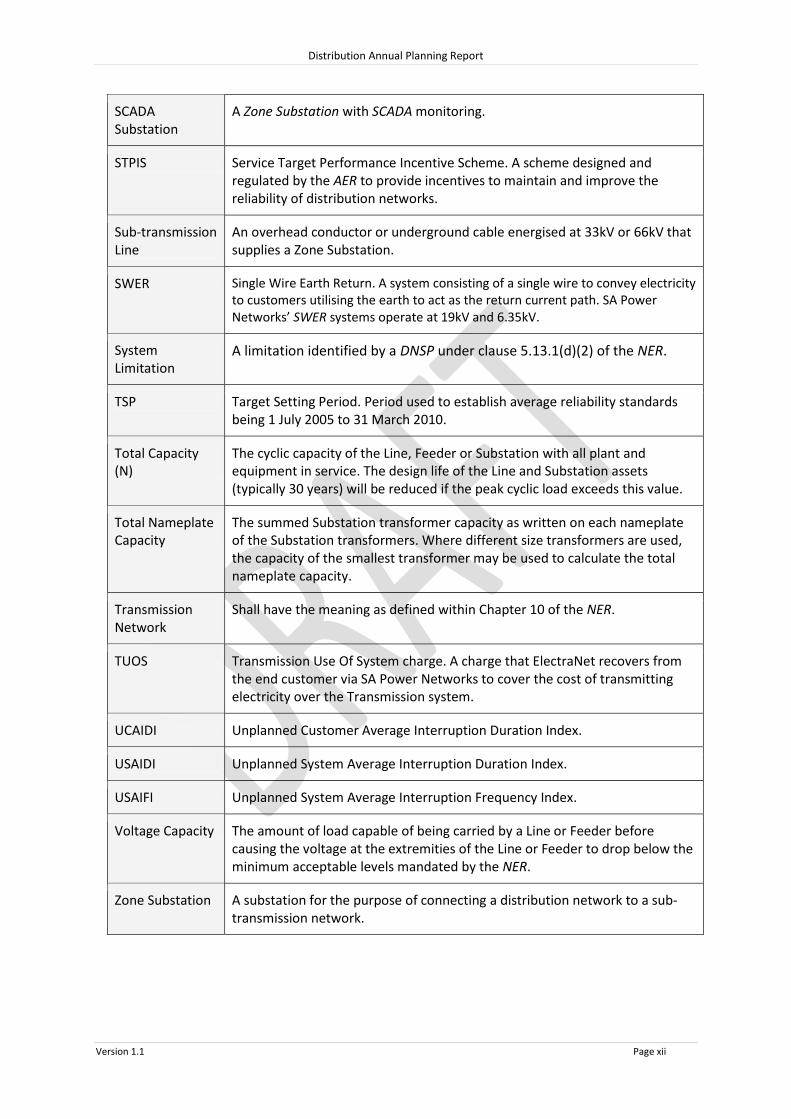
SCADA Substation
A Zone Substation with SCADA monitoring.
STPIS Service Target Performance Incentive Scheme. A scheme designed and regulated by the AER to provide incentives to maintain and improve the reliability of distribution networks.
Sub-transmission Line
An overhead conductor or underground cable energised at 33kV or 66kV that supplies a Zone Substation.
SWER Single Wire Earth Return. A system consisting of a single wire to convey electricity to customers utilising the earth to act as the return current path. SA Power Networks’ SWER systems operate at 19kV and 6.35kV.
System Limitation
A limitation identified by a DNSP under clause 5.13.1(d)(2) of the NER.
TSP Target Setting Period. Period used to establish average reliability standards being 1 July 2005 to 31 March 2010.
Total Capacity (N)
The cyclic capacity of the Line, Feeder or Substation with all plant and equipment in service. The design life of the Line and Substation assets (typically 30 years) will be reduced if the peak cyclic load exceeds this value.
Total Nameplate Capacity
The summed Substation transformer capacity as written on each nameplate of the Substation transformers. Where different size transformers are used, the capacity of the smallest transformer may be used to calculate the total nameplate capacity.
Transmission Network
Shall have the meaning as defined within Chapter 10 of the NER.
TUOS Transmission Use Of System charge. A charge that ElectraNet recovers from the end customer via SA Power Networks to cover the cost of transmitting electricity over the Transmission system.
UCAIDI Unplanned Customer Average Interruption Duration Index.
USAIDI Unplanned System Average Interruption Duration Index.
USAIFI Unplanned System Average Interruption Frequency Index.
Voltage Capacity The amount of load capable of being carried by a Line or Feeder before causing the voltage at the extremities of the Line or Feeder to drop below the minimum acceptable levels mandated by the NER.
Zone Substation A substation for the purpose of connecting a distribution network to a sub-transmission network.

Distribution Annual Planning Report
Version 1.1 Page xiii
Compliance Statement
Schedule 5.8 of the National Electricity Rules (NER) specifies the information which must be included within the Distribution Annual Planning Report. The following table indicates these requirements together with a cross reference to the relevant sections within this document where the applicable information is located.
NER Requirement Section No(s).
(a) information regarding the Distribution Network Service Provider and its network, including:
(1) a description of its network; 1.2
(2) a description of its operating environment; 1.2
(3) the number and types of its distribution assets; 1.2
(4) methodologies used in preparing the Distribution Annual Planning Report, including methodologies used to identify system limitations and any assumptions applied; and
2.2, 2.3
(5) analysis and explanation of any aspects of forecasts and information provided in the Distribution Annual Planning Report that have changed significantly from previous forecasts and information provided in the preceding year;
2.1
(b) forecasts for the forward planning period, including at least:
(1) a description of the forecasting methodology used, sources of input information, and the assumptions provided
2.1
(2) load forecasts: (i) at the transmission-distribution connection points; (ii) for sub-transmission lines; and (iii) for zone substations,
Including where applicable, for each item specified above: (iv) total capacity; (v) firm delivery capacity for summer periods and winter periods; (vi) peak load (summer or winter and an estimate of the number of hours per year that 95% of peak load is expected to be reached); (vii) power factor at time of peak load; (viii) load transfer capacities; and (ix) generation capacity of known embedded generating units;
8 (by region)
(3) forecasts of future transmission-distribution connection points (and any associated connection assets), sub-transmission lines and zone substations, including for each future transmission-distribution connection point and zone substation:
8 (by region)
Distribution Annual Planning Report
Version 1.1 Page xiv
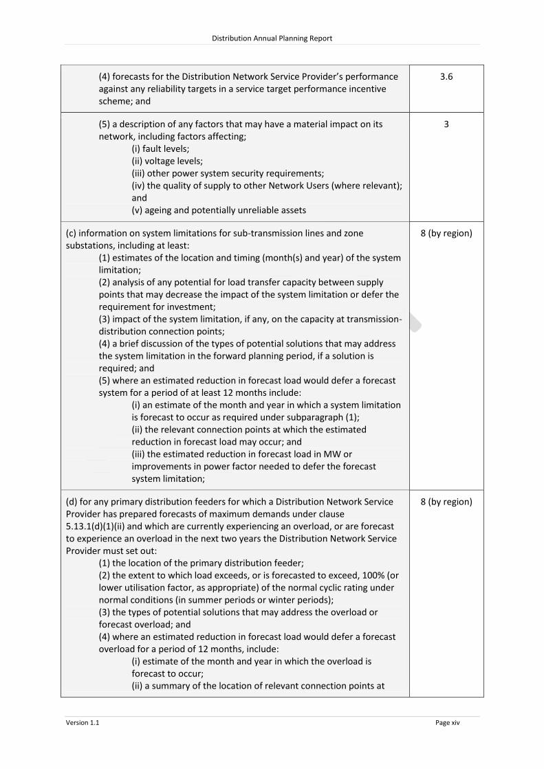
(4) forecasts for the Distribution Network Service Provider’s performance against any reliability targets in a service target performance incentive scheme; and
3.6
(5) a description of any factors that may have a material impact on its network, including factors affecting;
(i) fault levels; (ii) voltage levels; (iii) other power system security requirements; (iv) the quality of supply to other Network Users (where relevant); and (v) ageing and potentially unreliable assets
3
(c) information on system limitations for sub-transmission lines and zone substations, including at least:
(1) estimates of the location and timing (month(s) and year) of the system limitation; (2) analysis of any potential for load transfer capacity between supply points that may decrease the impact of the system limitation or defer the requirement for investment; (3) impact of the system limitation, if any, on the capacity at transmission-distribution connection points; (4) a brief discussion of the types of potential solutions that may address the system limitation in the forward planning period, if a solution is required; and (5) where an estimated reduction in forecast load would defer a forecast system for a period of at least 12 months include:
(i) an estimate of the month and year in which a system limitation is forecast to occur as required under subparagraph (1); (ii) the relevant connection points at which the estimated reduction in forecast load may occur; and (iii) the estimated reduction in forecast load in MW or improvements in power factor needed to defer the forecast system limitation;
8 (by region)
(d) for any primary distribution feeders for which a Distribution Network Service Provider has prepared forecasts of maximum demands under clause 5.13.1(d)(1)(ii) and which are currently experiencing an overload, or are forecast to experience an overload in the next two years the Distribution Network Service Provider must set out:
(1) the location of the primary distribution feeder; (2) the extent to which load exceeds, or is forecasted to exceed, 100% (or lower utilisation factor, as appropriate) of the normal cyclic rating under normal conditions (in summer periods or winter periods); (3) the types of potential solutions that may address the overload or forecast overload; and (4) where an estimated reduction in forecast load would defer a forecast overload for a period of 12 months, include:
(i) estimate of the month and year in which the overload is forecast to occur; (ii) a summary of the location of relevant connection points at
8 (by region)

Distribution Annual Planning Report
Version 1.1 Page xv
which the estimated reduction in forecast load would defer the overload; (iii) the estimated reduction in forecast load in MW needed to defer the forecast system limitation;
(e) a high level summary of each RIT-D project for which the regulatory investment test for distribution has been completed in the preceding year or is in progress;
Nil1
(f) for each identified system limitation which a Distribution Network Service Provider has determined will require a regulatory investment test for distribution, provide an estimate of the month and year when the test is expected to commence;
8 (by region)
(g) a summary of all committed investments to be carried out within the forward planning period with an estimated capital cost of $2 million or more (as varied by the cost threshold determination) that are to address:
(1) a refurbishment or replacement need; or (2) an urgent and unforseen network issue in clause 5.17.3.(a)(1).
4.3
(h) the results of any joint planning undertaken with a Transmission Network Service Provider in the preceding year, including:
(1) a summary of the process and methodology used by the Distribution Network Service Provider and relevant Transmission Network Service Providers to undertake joint planning;
(2) a brief description of any investments that have been planned through this process, including the estimated capital costs of the investment and an estimate of the timing (month and year)of the investment; and
(3) where additional information on the investments may be obtained;
2.4
(i) the results of any joint planning undertaken with other Distribution Network Service Providers in the preceding year; including:
(1) a summary of the process and methodology used by the Distribution Network Service Providers to undertake joint planning;
(2) a brief description of any investments that have been planned through this process, including the estimated capital costs of the investment and an estimate of the timing (month and year)of the investment; and
(3) where additional information on the investments may be obtained;
NA
(j) information on the performance of the Distribution Network Service Provider’s Network, including:
(1) a summary description of reliability measures and standards in applicable regulatory instruments;
(2) a summary description of the quality of supply standards that apply, including the relevant codes, standards and guidelines;
(3) a summary description of the performance of the distribution network against the measures and standards described under subparagraphs (1) and (2) for the preceding year;
(4) where the measures and standards described under subparagraphs (1) and (2) were not met in the preceding year, information on the corrective action taken or planned;
3
1 The AER’s new RIT-D commenced operation on 1 January 2014 and no project has had a RIT-D completed prior to 30 June 2014.

Distribution Annual Planning Report
Version 1.1 Page xvi
(5) a summary description of the Distribution Network Service Provider’s processes to ensure compliance with the measures and standards described under subparagraphs (1) and (2); and
(6) an outline of the information contained in the Distribution Network Service Provider’s most recent submission to the AER under the service target performance incentive scheme;
(k) information on the Distribution Network Service Provider’s asset management approach, including:
(1) a summary of any asset management strategy employed by the Distribution Network Service Provider;
(2) a summary of any issues that may impact on the system limitations identified in the Distribution Annual Planning Report that has been identified through carrying out asset management; and
(3) information about where further information on the asset management strategy and methodology adopted by the Distribution Network Service Provider may be obtained;
4
(l) information on the Distribution Network Service Provider’s demand management activities, including a qualitative summary of:
(1) non-network options that have been considered in the past year, including generation from embedded generating units;
(2) actions taken to promote non-network proposals in the preceding year, including generation from embedded generating units; and
(3) the Distribution Network Service Provider’s plans for demand management and generation from embedded generating units over the forward planning period;
5
(m) information on the Distribution Network Service Provider’s investments in metering or information technology systems which occurred in the preceding year, and planned investments in metering or information technology systems in the forward planning period; and
6
(n) a regional development plan consisting of a map of the Distribution Network Service Provider’s network as a whole, or maps by regions, in accordance with the Distribution Network Service Provider’s planning methodology or as required under any regulatory obligation or requirement, identifying:
(1) sub-transmission lines, zone substations and transmission-distribution connections points; and
(2) any system limitations that have been forecast to occur in the forward planning period, including, where they have been identified, overloaded primary distribution feeders.
8 (by region)

Distribution Annual Planning Report
Version 1.1 Page 1
1. Introduction and Network Overview
1.1 Purpose of this Report
The purpose of this report is to provide information about existing and forecast system limitations on SA Power Networks’ Distribution Network, where they are expected to arise within the forward planning period (five years). This report is published annually in accordance with the National Electricity Rules (NER), and provides the information specified in schedule 5.8. This report replaces the previously published ESDP (prior to 2013).
This report includes an overview of SA Power Networks’ system, its forecasting and planning methodology, 13 regional development plans as well as a separate plan for metropolitan 66kV lines. Each Regional Development Plan (RDP) includes forecasts for connection points and zone substations within the region for the forward planning period. Where system limitations are identified in the forward planning period, details of the limitation are outlined including the extent and timing as well as potential solutions to address the identified system limitations. A summary of those projects expected to be subject to the Regulatory Investment Test – Distribution (RIT-D) is included within each RDP along with an estimate of the month and year the assessments are expected to commence.
Further detail of SA Power Networks’ strategy to engage with third parties who may propose to connect a generator to our network or provide Network System Support Services can be found in our Demand Side Engagement Document (DSED):
http://www.sapowernetworks.com.au/centric/industry/our_network/annual_network_plans/demand_side_engagement_document.jsp

Distribution Annual Planning Report
Version 1.1 Page 2
1.2 Description of SA Power Networks' Distribution Network
SA Power Networks is responsible for planning, building and operating the distribution system within South Australia. Distribution system assets commence from the 66kV and 33kV Connection Points shared with ElectraNet. SA Power Networks’ assets include 66kV and 33kV buses, sub-transmission lines, zone substations, primary distribution feeders, street transformers, low voltage circuits and services to customers.
Figure 1: Electricity Supply Chain
400/230V

Distribution Annual Planning Report
Version 1.1 Page 3
SA Power Networks delivers electricity from the transmission network and embedded generators to more than 840,000 residential and business customers. The network has a route length of around 88,000 kilometres, which includes approximately 408 zone substations, more than 74,000 distribution transformers and over 720,000 Stobie poles.
SA Power Networks is the only Distribution Network Service Provider (DNSP) within South Australia and is 51% owned by Cheung Kong Infrastructure Holdings Limited and Power Assets Holdings Ltd, which form part of the Cheung Kong Group of companies. The remaining 49% is owned by ASX-listed Spark Infrastructure.
South Australia is part of the National Electricity Market (NEM) and as such SA Power Networks is bound by the NER as well as the local South Australian Electricity Distribution Code (EDC).
Figure 2: SA Power Networks’ network coverage

Distribution Annual Planning Report
Version 1.1 Page 4
2. Planning Standards and Procedures
2.1 Load Forecast Methodology
The SA Power Networks load forecast is reviewed annually after each summer peak load period, with the last review completed in 2014. This review considered the impact of any new peak load recordings, system modifications and new large load developments, in accordance with SA Power Networks’ Network Forecasting Procedures.
Several hot days were experienced in January and February 2014, with the system demand measured on the 16th of January approximately in line with that of a 10% Probability of Exceedance (POE) at 1900hrs (local summer time).
In 2013, SA Power Networks revised its load forecasting methodology to produce 10% POE and/or 50% POE forecasts for each element of the network. This methodology has been refined in 2014 by the use of a new forecasting tool.
In 2013/14 a new forecasting tool was developed for SA Power Networks by Acil Allen. This tool provides the ability to temperature correct (for different POE levels) and reconcile demand forecasts (Zone Substations to Transmission Connection Points and Connection Points to State total SA Power Networks demand). This year SA Power Networks chose to reconcile the Connection Points to the AEMO July 2014 National Electricity Forecasting Report (NEFR) forecast for South Australia – in particular the residential and commercial trend (reflecting approximately flat demand from 2014/15 to 2019/20). Through this reconciliation process AEMO’s view of State level population growth, energy efficiency and economic development were considered and factored into the forecast. Major customers (and those Connection Points dominated by major customers) were considered outside the model (based on customer advice) and added afterwards.
For the Electranet connection point substations 10% POE load forecasts were developed as required by the ElectraNet/SA Power Networks connection agreement. For zone substations, both a 10% and 50% POE forecast was developed.
The aggregated impact of customer solar photovoltaic (PV) generation has been considered in the forecasts based on measured performance of typical PV installations, installed PV capacity, time of peak demand, and forecasted PV growth rate.
The rapid growth in PV recorded in the last 3 years has been forecast to continue in the short term with a gradual slow down over the forward planning period. In some locations the rapid uptake in PV and the adoption of energy efficient appliances by customers is offsetting the substation load growth which may even be reflected as a net load decrease in the substation forecast. However, the impact of future PV growth on peak demand is expected to generally be minimal as the time of peak for most substations has shifted past 19:00hrs local summer time (when PV output is approaching zero).

Distribution Annual Planning Report
Version 1.1 Page 5
2.2 Network Planning Criteria
SA Power Networks’ Network Planning Criteria incorporate the objectives of maintaining compliance with all applicable Statutes, National and International Standards, Codes of Practice, the Electricity Act and NEM obligations. In particular, the criteria embody obligations imposed by legislation including the requirement to adhere to standards and practices generally accepted as appropriate internationally or throughout Australia by the electricity supply industry and to ensure the security of electricity supply to customers.
The forecast load for future years contained within the load forecast is compared against the capacity of the relevant network element to identify overloads or system limitations. This comparison is undertaken for both system normal (N) and contingency (N-1) conditions. For the transmission connection points and meshed sub-transmission system the 10% POE forecast is used. For zone substations, the 10% POE forecast is compared against the substations’ normal capacity (‘N’, i.e. all plant in service) and the 50% POE forecast is compared against the substations’ firm delivery capacity (‘N-1’, i.e. one item of plant out of service).
SA Power Networks plans to implement solutions for those assets that are forecast to be overloaded under normal conditions, prior to the overload occurring. However, the timing for implementation solutions for (N-1) forecasted contingency events considers both the likelihood and consequence of such an event and the amount and type of customer load at risk.
Typical repair times for major equipment categories are:
Zone Substation Transformer 7 Days
66kV Underground Cable 10 Days
66kV Circuit Breaker 7 Days
66kV Overhead Line 12 Hours
2.3 Summary of Planning Criteria for the Distribution Network
As a DNSP within the NEM, SA Power Networks must comply with technical standards in the NER. In particular, the requirements relating to reliability and system security contained in Schedule 5.1 of the Rules are relevant to planning for future electricity needs. In addition, as a licensed electricity entity in South Australia, SA Power Networks is required to comply with the service obligations imposed by the South Australian EDC. SA Power Networks is required to operate its power system within plant ratings and with acceptable Quality of Supply (QoS) under reasonably expected operating conditions in order to comply with its requirements under the NER and the EDC.
SA Power Networks has developed its Network Planning Criteria to meet and maintain the reliability requirements of the EDC and security of supply obligations of the NER. When the forecast load breaches the planning criteria, a system limitation is established and a suitable solution is sought.

Distribution Annual Planning Report
Version 1.1 Page 6
Solutions required to avoid breaching the asset ratings established within the planning criteria are considered where:
the overload cannot be eliminated by load transfers;
the conditions at a transmission Connection Point will not comply with the Electricity Transmission Code (ETC);
the 10% POE forecast exceeds an asset’s normal capacity;
the 10% POE forecast exceeds an asset’s emergency capacity during contingency conditions in the Central Business District (CBD) or Metropolitan 66kV Sub-transmission network.
the 50% POE forecast exceeds an asset’s emergency capacity during contingency conditions at all other locations;
the overload cannot be technically or economically eliminated by power factor correction;
the short circuit rating of the network may be exceeded during network faults; or
voltage cannot be maintained within the applicable standard.
The Network Planning Criteria for each asset type are defined in the following tables.
The likelihood and consequence of an asset failure affecting the impacted customers have been considered in establishing the planning criteria limits and a risk margin is generally applied to achieve a balance between minimising customer supply risk and capital expenditure.

Distribution Annual Planning Report
Version 1.1 Page 7
System Planning Criteria
Line outage
Interconnected CBD 66kV & 33kV Sub-transmission Lines
N-1 (Continuous)
No supplies interrupted for a single Line outage at 10% POE forecast demand – no impact on System Average Interruption Duration Index (SAIDI), Customer Average Interruption Duration Index (CAIDI) or System Average Interruption Frequency Index (SAIFI). No Sub-transmission Line loaded above emergency rating, and no Transmission Connection Point transformer above normal rating, as a consequence.
Meshed 66kV Sub-transmission Lines
N-1 (Continuous)
No supplies interrupted for a single Line outage at 10% POE forecast demand (excludes Substations teed off a Line and Substations without line circuit breakers) – no impact on SAIDI, CAIDI or SAIFI. No Sub-transmission Line loaded above emergency rating, and no Transmission Connection Point transformer above normal rating (as specified by ElectraNet), as a consequence. Risk limit: maximum 3 years from when threshold breached.
Radial 66kV Sub-transmission Line – Metropolitan Area
N Supplies may be interrupted for a single line outage, but all should be restorable, at 10% POE forecast demand, within 12 hours. May be achieved by repair, or by transfer of load to adjoining substations, without causing any other Line or transformer to be loaded above emergency rating (Contingency Plans to be prepared if Line contains cable, with preparatory work if required). An alternate supply (e.g. a second line) will be planned when the RIT-D shows a positive net benefit to customers, typically when load exceeds 30MVA. Definite impact on SAIFI, CAIDI and SAIDI due to up to 12 hour outage for customers.
Rural 66kV Sub-transmission Line
N As above, full supply to be restored within 12 hours. An alternate supply (e.g. a second line) will be planned when the RIT-D shows a positive net benefit to customers, typically when load exceeds 30MVA. Significant impact on SAIFI, CAIDI and SAIDI if outage is longer than 12 hours.
Rural 33kV Sub-transmission Line
N As above, but full supply to be restored within 12 hours for overhead line faults or 24 hours for 33kV cable faults. An alternate supply (e.g. a second line) will be planned when the RIT-D shows a positive net benefit to customers, typically when load exceeds 30MVA. Significant impact on SAIFI, CAIDI and SAIDI if outage is longer than 12 hours.
Table 2-1 Planning Criteria for Sub-transmission Systems

Distribution Annual Planning Report
Version 1.1 Page 8
System Planning Criteria
Impact of transformer outage
All assets N No assets overloaded at 10% POE forecast demand
All City of Adelaide 66/33kV and 66/11kV Substations
N-1 (Continuous)
No supplies interrupted for a single transformer outage at 10% POE forecast demand – no impact on SAIDI, SAIFI or CAIDI. No other transformer loaded above emergency rating as a consequence.
Specific Major Zone Substations, for example:
Edinburgh
LeFevre
N-1 (Continuous)
No supplies interrupted for a single transformer outage at 50% POE forecast demand – no impact on SAIDI, SAIFI or CAIDI. No other transformer loaded above emergency rating as a consequence.
Zone Substations
N-1 + Feeder transfers
+ Risk Margin
Supplies may be interrupted for a single transformer outage, however all but the risk margin should be restorable following transfer of load to adjoining Zone Substations, at 50% POE forecast demand, without causing any equipment to be loaded above emergency rating. Risk margin limited to 0MVA for Zone Substation where: a) Critical major industrial or commercial customers exist, for example:
Elizabeth South
Woodville
North Adelaide
Kilkenny
Kent Town
Norwood
Direk b) Contingency plans cannot be implemented to restore supply within 24 hours, for example 66/7.6kV substations where SA Power Networks mobile plant cannot be used. Risk margin limited to 3MVA of customer load at all other locations.
Table 2-2 Planning Criteria for Substations
System Transformer outage ‘ideal’
Transmission Connection Points Refer to the Electricity Transmission Code Table 2-3 Planning Criteria for Transmission Connection Points
Note that Transmission Connection Points designated by the ETC as Category 1 may not have adequate backup capacity under contingency conditions (via ElectraNet or SA Power Networks) to supply the load until ElectraNet’s repairs are complete.

Distribution Annual Planning Report
Version 1.1 Page 9
2.4 Joint Planning
Network Planning personnel from SA Power Networks and ElectraNet undertake regular joint planning meetings to discuss system limitations and future projects that affect both the distribution and transmission networks.
These joint planning meetings address the following issues:
Annual Planning
Load Forecasts for connection points
Network replacement projects
Network augmentation projects
Major customer (including generator) connections that may impact both the transmission and distribution networks
Non-network solutions
In addition to regular meetings SA Power Networks and ElectraNet jointly manage an annual Connection Point Management Plan (CPMP) which outlines expected projects that affect connection points within the forward planning period.
In general, works by Electranet at connection points, whether augmentation or asset replacement, will affect SA Power Networks’ assets and require expenditure by SA Power Networks.
Investments that have been planned through this process that impact on SA Power Networks’ expenditure in the forward planning period include:
Project Timing Anticipated Cost (SA Power Networks only)
Neuroodla 132/33kV Rebuild 2014/15 <$1M
Mount Gunson 132/33kV Rebuild
2015/16 <$2M
Dalrymple 132/33kV Upgrade 2016/17 $4.6M
Baroota 132/33kV Rebuild 2017/18 $5.1M
Table 2-4 Major joint investments in forward planning period
Further details of ElectraNet’s planned projects in the forward planning period can be found in their Transmission Annual Planning Report at:
http://www.electranet.com.au/network/transmission-planning/transmission-annual-planning-report/

Distribution Annual Planning Report
Version 1.1 Page 10
3. Network Performance
3.1 Measures and standards of Reliability
In accordance with the EDC clause 1.1.3, SA Power Networks must use its best endeavours to achieve the following unplanned interruption Reliability Service Standards (RSS) for each year ending 30 June.
SAIDI and SAIFI Standards SAIDI* (average minutes off supply per customer per annum)
SAIFI* (average no. of supply Interruptions per customer per annum)
Region
Adelaide Business Area 25 0.25
Major Metropolitan Areas 130 1.45
Barossa, Mid North, Yorke Peninsula, Riverland, Murraylands
260 1.80
Eastern Hills & Fleurieu Peninsula 295 2.80
Upper North & Eyre Peninsula 425 2.30
South East 295 2.50
Kangaroo Island 450 N/A
Table 3-1 – 2013/14 Unplanned Reliability performance excluding Major Event Days
*Note: These standards reflect unplanned supply interruptions on the low voltage and high voltage distribution
networks but exclude any planned supply interruptions and supply interruptions of a duration less than 1
minute.
The RSS use a number of metrics to measure the performance of a DNSP as defined in Table 3-2.
Indicator Description
USAIFI (Unplanned System Average Interruption Frequency Index)
The average number of times a customer experiences an unplanned interruption each year.
USAIDI (Unplanned System Average Interruption Duration Index)
The total number of minutes on average that a customer is without electricity in a year, due to an unplanned interruption.
Table 3-2 Reliability measures
Different reliability levels (i.e. the value of the measure) were established for each region specified due to the varying nature of the electricity network (eg interconnectivity2 and area covered) across
2 This relates to the ability for the distribution network within a region of being capable to being switched (ie supply route changed) to restore electricity supply to customers without the need to repair the fault that caused the interruption. Such interconnectivity is greater in some regions than others.

Distribution Annual Planning Report
Version 1.1 Page 11
the State. The regional reliability target levels (targets) were based on the average historic performance over the period 1 July 2005 to 31 March 2010. This period is known as the Target Setting Period (TSP). It should be noted that SA Power Networks can still achieve the RSS despite the reliability performance being worse than target (e.g. due to the impact of severe weather events) if it has been assessed as having used best endeavours to meet the target. SA Power Networks’ performance against these reliability targets in 2013/14 is outlined in Section 3.3 below. Additionally, a Guaranteed Service Level (GSL) regime under 1.1.4 of the EDC operates in South Australia which requires SA Power Networks to make payments to customers if supply to their supply address is interrupted and such an interruption exceeds certain frequency and duration thresholds. There are two types of GSL payments existing under this regime, which are:
frequency of interruptions, where a payment is made to a customer who has experienced 10 or more interruptions in the year ending 30 June; and
duration of an interruption, where a payment is made to a customer who has experienced an interruption to supply of more than 12 hours.
Note: the GSL payment amount is dependent on the number of interruptions and the duration once the initial threshold detailed above is exceeded.
3.2 Quality of supply standards
SA Power Networks is required under the NER and EDC to maintain an acceptable voltage at the customer’s point of connection to its network infrastructure. Specifically the following standards apply:
At the customer’s supply address: (i) the voltage is as set out in AS 60038; (ii) the voltage fluctuations that occur are contained within the limits as set out in AS/NZS 61000
Parts 3.3 and 3.5 and AS2279 Part 4; and (iii) the harmonic voltage distortions do not exceed the values in AS/NZS 61000 Part 3.2 and
AS2279 Part 2 and as specified by the distributor.
SA Power Networks responds to Quality of Supply (QoS) enquiries from customers with follow-up testing and measurement to determine if the distribution network is the cause of the customer’s problem. SA Power Networks’ internal target for completing and advising customers of the conclusion of the investigation is 75% within 20 business days. Where that investigation determines that remedial works are required, those works are normally completed within 60 business days except where major infrastructure works are required. In those cases customers are provided with a program and a date when the work will be completed3.
3 In most case some initial remedial works will be completed to improve the customer’s QoS with any required major infrastructure works completed in full prior to the next peak load, when the customer would otherwise likely experience the QoS issue again.
Distribution Annual Planning Report
Version 1.1 Page 12
3.3 SA Power Networks’ performance in 2013/14
3.3.1 Reliability Performance
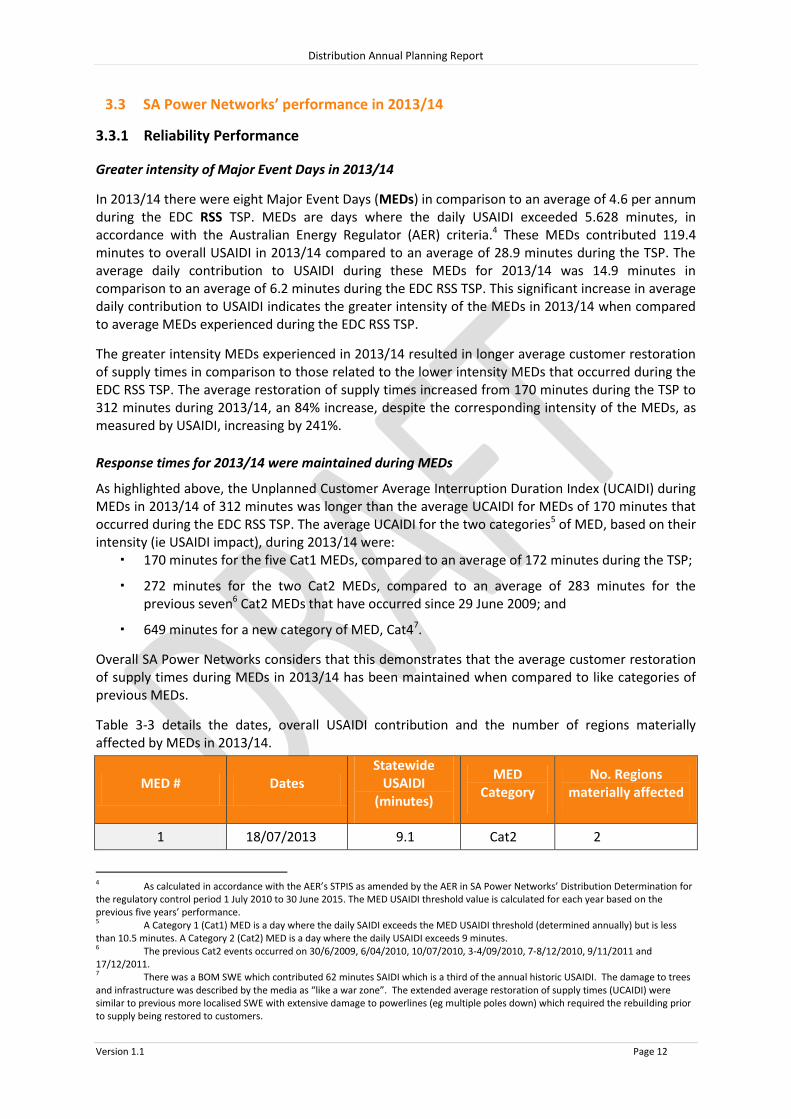
Greater intensity of Major Event Days in 2013/14
In 2013/14 there were eight Major Event Days (MEDs) in comparison to an average of 4.6 per annum during the EDC RSS TSP. MEDs are days where the daily USAIDI exceeded 5.628 minutes, in accordance with the Australian Energy Regulator (AER) criteria.4 These MEDs contributed 119.4 minutes to overall USAIDI in 2013/14 compared to an average of 28.9 minutes during the TSP. The average daily contribution to USAIDI during these MEDs for 2013/14 was 14.9 minutes in comparison to an average of 6.2 minutes during the EDC RSS TSP. This significant increase in average daily contribution to USAIDI indicates the greater intensity of the MEDs in 2013/14 when compared to average MEDs experienced during the EDC RSS TSP.
The greater intensity MEDs experienced in 2013/14 resulted in longer average customer restoration of supply times in comparison to those related to the lower intensity MEDs that occurred during the EDC RSS TSP. The average restoration of supply times increased from 170 minutes during the TSP to 312 minutes during 2013/14, an 84% increase, despite the corresponding intensity of the MEDs, as measured by USAIDI, increasing by 241%.
Response times for 2013/14 were maintained during MEDs
As highlighted above, the Unplanned Customer Average Interruption Duration Index (UCAIDI) during MEDs in 2013/14 of 312 minutes was longer than the average UCAIDI for MEDs of 170 minutes that occurred during the EDC RSS TSP. The average UCAIDI for the two categories5 of MED, based on their intensity (ie USAIDI impact), during 2013/14 were:
170 minutes for the five Cat1 MEDs, compared to an average of 172 minutes during the TSP;
272 minutes for the two Cat2 MEDs, compared to an average of 283 minutes for the previous seven6 Cat2 MEDs that have occurred since 29 June 2009; and
649 minutes for a new category of MED, Cat47.
Overall SA Power Networks considers that this demonstrates that the average customer restoration of supply times during MEDs in 2013/14 has been maintained when compared to like categories of previous MEDs.
Table 3-3 details the dates, overall USAIDI contribution and the number of regions materially affected by MEDs in 2013/14.
MED # Dates Statewide
USAIDI (minutes)
MED Category
No. Regions materially affected
1 18/07/2013 9.1 Cat2 2
4 As calculated in accordance with the AER’s STPIS as amended by the AER in SA Power Networks’ Distribution Determination for the regulatory control period 1 July 2010 to 30 June 2015. The MED USAIDI threshold value is calculated for each year based on the previous five years’ performance. 5 A Category 1 (Cat1) MED is a day where the daily SAIDI exceeds the MED USAIDI threshold (determined annually) but is less than 10.5 minutes. A Category 2 (Cat2) MED is a day where the daily USAIDI exceeds 9 minutes. 6 The previous Cat2 events occurred on 30/6/2009, 6/04/2010, 10/07/2010, 3-4/09/2010, 7-8/12/2010, 9/11/2011 and 17/12/2011. 7 There was a BOM SWE which contributed 62 minutes SAIDI which is a third of the annual historic USAIDI. The damage to trees and infrastructure was described by the media as “like a war zone”. The extended average restoration of supply times (UCAIDI) were similar to previous more localised SWE with extensive damage to powerlines (eg multiple poles down) which required the rebuilding prior to supply being restored to customers.
Distribution Annual Planning Report
Version 1.1 Page 13
MED # Dates Statewide
USAIDI (minutes)
MED Category
No. Regions materially affected
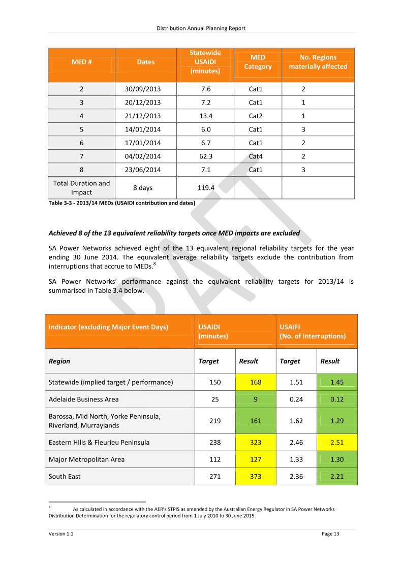
2 30/09/2013 7.6 Cat1 2
3 20/12/2013 7.2 Cat1 1
4 21/12/2013 13.4 Cat2 1
5 14/01/2014 6.0 Cat1 3
6 17/01/2014 6.7 Cat1 2
7 04/02/2014 62.3 Cat4 2
8 23/06/2014 7.1 Cat1 3
Total Duration and Impact
8 days 119.4
Table 3-3 - 2013/14 MEDs (USAIDI contribution and dates)
Achieved 8 of the 13 equivalent reliability targets once MED impacts are excluded
SA Power Networks achieved eight of the 13 equivalent regional reliability targets for the year ending 30 June 2014. The equivalent average reliability targets exclude the contribution from interruptions that accrue to MEDs.8
SA Power Networks’ performance against the equivalent reliability targets for 2013/14 is summarised in Table 3.4 below.
Indicator (excluding Major Event Days) USAIDI (minutes)
USAIFI (No. of Interruptions)
Region Target Result Target Result
Statewide (implied target / performance) 150 168 1.51 1.45
Adelaide Business Area 25 9 0.24 0.12
Barossa, Mid North, Yorke Peninsula, Riverland, Murraylands
219 161 1.62 1.29
Eastern Hills & Fleurieu Peninsula 238 323 2.46 2.51
Major Metropolitan Area 112 127 1.33 1.30
South East 271 373 2.36 2.21
8 As calculated in accordance with the AER’s STPIS as amended by the Australian Energy Regulator in SA Power Networks Distribution Determination for the regulatory control period from 1 July 2010 to 30 June 2015.

Distribution Annual Planning Report
Version 1.1 Page 14
Upper North & Eyre Peninsula 330 345 1.89 1.57
Kangaroo Island 371 358 N/A 2.59
Table 3-4 – 2013/14 Unplanned Reliability performance excluding Major Event Days
When the performance on MEDs is included SA Power Networks achieved eight of the 13 EDC regional RSS targets for the year ending 30 June 2014. As the targets are based on historic average reliability performance it is expected that on average 6.5 targets (i.e. half) would be achieved each year. However, on average 7.4 targets were achieved during the TSP with the minimum being four in 2006/07 and the maximum of 12 in 2007/08.
Table 3-5 below details the RSS targets and the actual performance in 2013/14 including MED performance
Table 3-5 below details the RSS targets and the actual performance in 2013/14 including MED performance
Indicator (including Major Event Days) USAIDI (minutes)
USAIFI (No. of Interruptions)
Region Target Result Target Result
Statewide (implied target / performance) 179 287 1.68 1.83
Adelaide Business Area 25 9 0.25 0.12
Barossa, Mid North, Yorke Peninsula, Riverland, Murraylands
260 242
1.80 1.59
Eastern Hills & Fleurieu Peninsula 295 425 2.80 2.90
Major Metropolitan Area 130 265 1.45 1.72
South East 295 427 2.50 2.45
Upper North & Eyre Peninsula 425 390 2.30 1.69
Kangaroo Island 450 385 N/A 2.85
Table 3-5 2013/14 Overall Unplanned Reliability performance
Note: a cell highlighted in yellow indicates that the reliability target was not achieved but in all cases SA Power Networks has reported to the Essential Services Commission of South Australia (ESCOSA) that it has used best endeavours to achieve the specified target9.
3.3.2 GSL Performance
The results for 2013/14 GSL payments are summarised in Table 3.6 below
9 As reported in our Annual Operational Performance Report to ESCoSA for the year ending 30 June 2014.

Distribution Annual Planning Report
Version 1.1 Page 15
Frequency GSLs Duration GSLs
No. of payments 3,629 51,2861
Amount paid $0.35m $9.4m
Table 3-6 GSL Performance
1 Our performance was adversely impacted by eight (8) severe storms classified as Major Event Days (MEDs) in 2013/14, which accounted for approximately89% of GSL duration payments
3.3.3 Quality of Supply Performance
SA Power Networks utilises the following measures to determine compliance with the QoS standards, with the measures being:
how quickly a customer’s QoS enquiry is investigated and a response provided, with the target for a response10 being 75% within 20 business days;
how quickly the works are completed that remedies the customer QoS problem, with the target being within 60 business days11; and
the number of instances where the distribution network required works to remedy the customer’s QoS problem per thousand customers.
SA Power Networks’ performance during 2013/14 in accordance with these measures was that: 92% of customers were advised on the outcome of the investigation within 20 business days;
88% of works were completed within 60 business days; and
There were 0.4 customers per 1,000 customers who enquired about a QoS problem and it was determined that the distribution network (ie network required works to remedy) was the cause.
In addition the number of customer complaints that are related to their QoS, was 15 complaints in 2013/14 which is slightly more than half the historic average of 26 since 1 July 2005.
Customer Enquiries Changes required to distribution
system
No. per 1,000 customers
% advised in 20 business days
No. per 1,000 customers
% completed in 60 business days
2005/06 1.9 87% 1.0 65%
2006/07 1.8 88% 0.7 70%
2007/08 1.7 86% 0.7 76%
2008/09 2.4 85% 0.6 72%
2009/10 2.7 89% 0.8 82%
2010/11 2.6 93% 0.5 95%
2011/12 2.5 90% 0.5 94%
2012/13 2.7 88% 0.7 89%
2013/14 2.6 92% 0.4 88%
10 A response includes advising the customer of the findings of the investigation and the proposed remedy. 11 The 60 business days are in addition to the 20 business days allowed to determine what work is required.

Distribution Annual Planning Report
Version 1.1 Page 16
Table 3-7 QoS statistics
The Table above indicates that despite the increase in the number of QoS enquiries from 2005/06 to 2013/14, there has not been an increase in the instances where the distribution network was the cause of the enquiry. The increase in the number of enquiries has been a result of the rapid up take in residential solar PV systems.

Distribution Annual Planning Report
Version 1.1 Page 17
3.4 SA Power Networks’ Reliability and Quality of Supply Monitoring
Once SA Power Networks has indentified distribution service reliability or QoS issues, a range of potential solutions will typically be indentified, analysed and then a preferred solution selected. Depending on the cause of the reliability or QoS issue, the solution may be able to be implemented immediately or, if the project requires significant planning and design, or consultation with other stakeholders, it will take longer to implement.
Solutions include:
Additional protective devices on the network to reduce the number of customers affected by a fault.
Installation of voltage regulators which will bring voltage levels at customer connection points within the QoS standards specified in the EDC. These regulators can be required where localised generation exists, such as solar photovoltaic generators.
The upgrade of existing distribution transformers, or the installation of new distribution transformers, to increase the ability of the network to meet customers’ demand for electricity.
Vegetation management which reduces the probability of significant damage or an interruption from tree limbs making contact with our assets.
Powerline and substation inspections identifying aging or defective equipment, so that those defects can be preventatively repaired prior to failure, which helps prevent an unplanned interruption.
Actions taken or planned to be taken to meet the RSS, which aim to ensure compliance, are detailed in our Reliability Management Plan, which is reviewed and implemented annually.
3.5 Annual AER submission on Service Target Performance Incentive Scheme (STPIS)
3.5.1 Outline of Information Provided to AER on the STPIS
Information is provided to the AER regarding STPIS performance each year in the annual response to the AER’s Regulatory Information Notice (RIN). Our submission to the AER under the STPIS regime includes:
STPIS feeder category performance;
Telephone call responsiveness expressed as the percentage of calls answered in 30 seconds;
Daily STPIS feeder category performance;
MED threshold data;
STPIS exclusions, which include:
o Transmission failures;
o Police, Fire, Emergency Services isolations;
o Generation failures;
o Emergency disconnections; and
o Single customer faults (where fault is in customer’s electrical installation).

Distribution Annual Planning Report
Version 1.1 Page 18
3.5.2 2013/14 STPIS Feeder Category Performance
The following Table details the submission to the AER on the STPIS feeder category performance for the regulatory year ending 30 June 2014 (ie 2013/14).
CBD Urban Short Rural Long Rural
Whole Network
SAIDI (minutes)
Total 9.0 268.9 264.9 410.1 289.8
Total (less excluded events)
9.0 128.7 197.0 314.1 167.6
SAIFI (no. of interruptions)
Total 0.116 1.811 1.915 2.819 1.979
Total (less excluded events)
0.115 1.304 1.596 1.973 1.446
Table 3-8 2013/14 STPIS Feeder Category Performance
3.5.3 Forecasts for Performance against STPIS
SA Power Networks implements improvements to reliability performance under the STPIS regime where those improvements are considered cost effective. However, even with the exclusion of MEDs under the STPIS, reliability performance can still be volatile due to the significant impacts of weather related interruptions. Consequently, it is not possible to forecast the reliability performance for any specific year (eg 2014/15).

Distribution Annual Planning Report
Version 1.1 Page 19
4. Asset Management
4.1 Introduction
SA Power Networks Asset Management Policy states that the organisation is committed to managing its assets to provided valued services to our customers; comply with Licence and Regulatory obligations; provide a safe environment for employees, contractors and the community; and deliver optimal returns to shareholders. SA Power Networks will employ good asset management practice to deliver value from assets, to manage the life cycle of assets prudently and efficiently, and to ensure the long term sustainable performance and condition of the assets. The Asset Management Strategies, Objectives and Plans will be founded on provision of the levels of service that our customers and the community seek and are prepared to pay for, delivered the most cost effective way, whilst also meeting Regulatory obligations and Corporate Strategic Objectives. SA Power Networks shall establish, implement and maintain processes and procedures for identifying opportunities and assessing, prioritising and implementing actions to achieve continual improvement in asset management. SA Power Networks’ Asset Management includes risk management for the whole of life consideration of procurement, operation, maintenance, condition and performance monitoring, disposal or replacement and legal compliance. It includes assets, tangible or intellectual property, owned or leased and those owned by clients if part of an asset management contract. It also includes long term planning and provision of assets for current and future services.
4.2 Asset Management Strategy
Effective implementation of asset management requires a disciplined approach which enables SA Power Networks to maximise value and deliver its strategic objectives through consideration and management of its assets over their whole life cycle including procurement, operation, maintenance, condition and performance monitoring, and disposal or replacement. The key principles and attributes of good asset management practice are an integrated approach with attributes which are holistic, systematic, systemic, risk based, optimal and sustainable. There are different models for organising roles and responsibilities to achieve this objective. The overall asset management strategy is to strive to optimise capital expenditure investment though targeted replacement and refurbishment of assets, based on an assessment of asset condition and risk. This Asset Management Strategy also seeks to provide sustainable lifecycle management of assets through use of condition monitoring and life assessment techniques. The work undertaken in delivery of this strategy is as follows:
Long term planning for the management of assets considering expected end of life of each asset, asset class or sub-class, performance history, condition information, age and also industry experience.
Management of each distribution network asset at the optimum class and sub-class level to deliver long term sustainable performance and optimum return to shareholders;
Design and implementation of a maintenance and replacement strategy for each asset sub-class that enables delivery of known regulated performance standards and the business’ accepted level of risk;

Distribution Annual Planning Report
Version 1.1 Page 20
Development and maintenance of the asset information systems and standards to ensure compliance with Regulations, Industry standards and enable effective asset management decision making;
Selection of the optimum maintenance and replacement strategy for each asset sub-class that is technically feasible, economically viable (lowest NPV over life of asset), and delivers a “low” residual risk against SA Power Networks’ risk strategy measure;
Determination of the optimum spares holdings required to deliver the regulated standards and customer expectations;
Integration with the Capacity and Customer Connect asset management strategies; and
Documenting a detailed asset management plan to meet the selected strategy with a 20 year horizon and a 10 year detailed task and expenditure forecast.
There is a common profile to asset life-cycles. The life-cycle commences in its concept/design and culminates in its disposal or demolition. Each of the phases of asset life will attract a type of activity which is cognisant of the phase and which should be reflected in the budget.
The schedule of tasks undertaken during each phase will be dependent on the specific failure modes which are common to each. For example, asset replacement cycles will be driven by asset condition, size, maintainability, utilisation and functionality assessments.
Figure 3: Asset Life-Cycle
An important consideration in determining the management strategy for an asset is to understand the principle failure mode(s) of the asset. Nominally there are four predominant failure modes feasible, each with their own distinct characteristics. For each failure mode there is generally a corresponding optimal strategy to manage the asset.
Distribution Annual Planning Report
Version 1.1 Page 21
4.3 Committed Asset Refurbishment or Replacement Projects
The following asset refurbishment/replacement projects with an estimated capital cost greater than $2M are committed for the forward planning period:
Port Pirie 6.6kV switchboard replacement
The Port Pirie 6.6kV switchboard and switch room were constructed in the early 1950’s. The switch room is suffering from subsidence and the switchboard has been damaged as a result with imminent catastrophic failure forecasted (confirmed by external independent expert). It is proposed to construct a new switch room and install a new 6.6kV switchboard in 2015 at an estimated capital cost in the order of $5M. The augmentation impact of this project is nil (i.e. no increase in capacity of the network). There are no demand side participation options that would allow the replacement of the switchboard to be deferred.
Mannum Town 33/7.6kV Transformer replacement
Mannum Town 33/7.6kV Substation has two 2.5MVA transformers aged 61 & 65 years. Remediation of the site is required to prevent contamination of ground water due to oil leaks, near the River Murray. It is proposed to construct a new substation in 2016 adjacent to the existing, prior to demolition and remediation of the old site at an estimated capital cost in the order of $4M. The new substation is proposed to consist of two 3MVA 33/7.6kV standard transformers and associated switchgear. The project will marginally increase the capacity of the substation (nameplate increase from 5MVA to 6MVA). There are no demand side participation options that would allow deferral of the substation replacement.
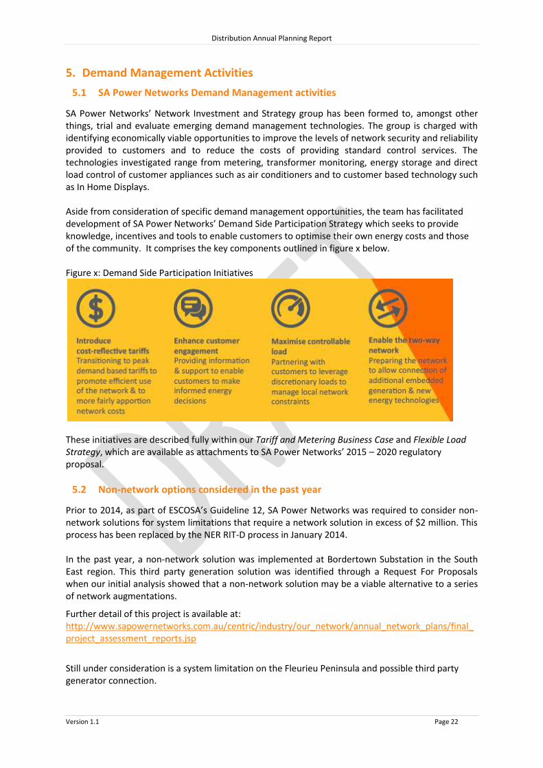
Distribution Annual Planning Report
Version 1.1 Page 22
5. Demand Management Activities
5.1 SA Power Networks Demand Management activities
SA Power Networks’ Network Investment and Strategy group has been formed to, amongst other things, trial and evaluate emerging demand management technologies. The group is charged with identifying economically viable opportunities to improve the levels of network security and reliability provided to customers and to reduce the costs of providing standard control services. The technologies investigated range from metering, transformer monitoring, energy storage and direct load control of customer appliances such as air conditioners and to customer based technology such as In Home Displays. Aside from consideration of specific demand management opportunities, the team has facilitated development of SA Power Networks’ Demand Side Participation Strategy which seeks to provide knowledge, incentives and tools to enable customers to optimise their own energy costs and those of the community. It comprises the key components outlined in figure x below. Figure x: Demand Side Participation Initiatives
These initiatives are described fully within our Tariff and Metering Business Case and Flexible Load Strategy, which are available as attachments to SA Power Networks’ 2015 – 2020 regulatory proposal.
5.2 Non-network options considered in the past year
Prior to 2014, as part of ESCOSA’s Guideline 12, SA Power Networks was required to consider non-network solutions for system limitations that require a network solution in excess of $2 million. This process has been replaced by the NER RIT-D process in January 2014. In the past year, a non-network solution was implemented at Bordertown Substation in the South East region. This third party generation solution was identified through a Request For Proposals when our initial analysis showed that a non-network solution may be a viable alternative to a series of network augmentations.
Further detail of this project is available at: http://www.sapowernetworks.com.au/centric/industry/our_network/annual_network_plans/final_project_assessment_reports.jsp
Still under consideration is a system limitation on the Fleurieu Peninsula and possible third party generator connection.

Distribution Annual Planning Report
Version 1.1 Page 23
5.3 Actions taken to promote non-network proposals
SA Power Networks has developed and published its Demand Side Engagement Document (DSED). This document provides a guide to third parties of how SA Power Networks will consider and assess the viability of any non-network solutions. This document is subject to review and revision at least once every three years. All recent investments in excess of $2 million have undergone a Reasonableness Test to determine whether a non-network solution would be viable. For those projects where a non-network solution was potentially viable based on the Non-Network Options Evaluation Framework a Request for Proposals was published and sent to registered interested parties to request proposals. This process has been replaced with the RIT-D, requiring augmentation investments in excess of $5 million to undergo a Screening Test. Further details of our engagement strategy can be found on our website at: http://www.sapowernetworks.com.au/centric/industry/our_network/annual_network_plans/demand_side_engagement_register.jsp
5.4 Plans for future Demand Management and embedded generation
SA Power Networks recognises that alternatives to network solutions may exist which deliver either a lower cost solution or provide greater benefits to the electricity market (including electricity consumers) as a whole. The methods by which non-network solutions may achieve this include, but are not limited to:
the use of embedded generation to reduce demand on the network;
shifting consumption to a period outside the peak period;
increasing customers’ energy efficiency; or
curtailing demand at peak periods, with the agreement of the relevant customer(s).
We evaluate all options, both network and non-network, using identical criteria that reflect both the regulatory requirements under the NER and our desire to implement the least cost solution to resolve the identified need. Two system limitations forecast in the next five years may have a potentially viable non-network solution (generation) which will be evaluated via the NER process. In addition two smaller network constraints may have potentially viable non-network deferral solutions which will be explored via the NER process during the evaluation period. This process is set out in more detail in section 6.6 of our DSED. A copy of the DSED can be found on our website at: http://www.sapowernetworks.com.au/centric/industry/our_network/annual_network_plans/demand_side_engagement_document.jsp Further to the initiatives identified through the RIT-D process, SA Power Networks is also proactively continuing trials of direct load control and cost reflective tariffs.

Distribution Annual Planning Report
Version 1.1 Page 24
6. Metering and information technology systems
SA Power Networks has continued the implementation of an Advanced Distribution Management System (ADMS). The system provides for distribution network monitoring, analysis, operations and restoration functions. The project implementation will take more than three years and replaces an aging system that is reaching the end of its effective working life.
Over the past year, SA Power Networks has continued to install ‘next generation’ digital interval meters into our trial area in North Adelaide to support our demand management trials and capacity tariff trials. We have also established a second trial area south of Greenhill Road to test an alternative communication technology for advanced meters, to enable the costs and benefits to be better understood.
We have also continued to trial monitoring of selected low voltage transformers to provide real-time visibility of our distribution transformers.

Distribution Annual Planning Report
Version 1.1 Page 25
7. Metropolitan 66kV Sub-transmission Network
SA Power Networks' metropolitan 66kV supply network consists of four 66kV meshed systems that distribute the customer demand from ElectraNet connection points to SA Power Networks' metropolitan zone substations.
The supply capacity of the meshed 66kV network is dependent on the individual lines and circuit breakers comprising the network. The ElectraNet connection point substations supplying these meshed 66kV networks are defined in the ETC generally as category 4 or 5, requiring firm delivery capacity to be continuously available.
The connection agreement between ElectraNet and SA Power Networks requires that the 10% POE demand forecast is used for planning category 4 and 5 networks.
The network planning criteria identifies a network system limitation if the 10% POE forecast exceeds the emergency rating of a 66kV line or the agreed maximum emergency capability of an ElectraNet Connection Point during an N-1 conditional outage of a single 66kV line or a single ElectraNet connection transformer.
The ETC specifies the planning limits for ElectraNet Connection Points but does not provide specific planning limits for the 66kV meshed networks. However, the EDC does specify the reliability targets for each region and SA Power Networks’ Planning Criteria are designed to maintain the average levels of reliability specified in the EDC and meet the NER’s requirement to maintain loads within the rating of the DNSP’s plant and equipment.
7.1 Need for Reinforcement of Sub-transmission System Security
Reinforcement of the meshed sub-transmission networks is designed to prevent overload of 66kV lines at peak load times during certain single contingency events. This avoids the need for load shedding and the possibility of cascade tripping of the entire affected 66kV network which could otherwise occur during contingency events.
7.2 Rating Limits of 66kV Lines
This report has considered line overloads that are the result of circuit breaker, line conductor, or underground cable limits. ElectraNet transformer overloads have been based on the agreed maximum demand capability of each connection point transformer as published by ElectraNet.
When circuit breakers are required to operate outside their design capabilities (current ratings and/or fault ratings) there is a risk of catastrophic failure. Failure of a breaker would require the upstream breaker to operate resulting in loss of supply to large parts of the network. Depending on the extent of the damage to the circuit breaker, restoration could take from several days to two weeks.
Overhead line conductor deteriorates gradually depending on the temperature at which it is operated. Currently, SA Power Networks' 66kV lines are designed and operated for a maximum line conductor temperature of 100 degrees Celsius, with some older lines built to lower temperature limits. The typical outage duration for a metropolitan 66kV line outage due to an overhead line fault is 12 hours.
Underground cable faults can occur in two ways. Cables can fail in either specific locations due to site conditions such as termites or being struck during digging, or they can fail due to general deterioration caused by prolonged overload. In the first case, the typical duration of a 66kV cable outage is ten to fourteen days to allow for fault location and repair. In the second case, the cable may remain out of service for six to nine months (depending on cable delivery time) while it is replaced.

Distribution Annual Planning Report
Version 1.1 Page 26
8. Regional Development Plans
8.1 Metropolitan 66kV lines 8.3 Eastern Suburbs 8.4 Western Suburbs 8.5 Northern Suburbs 8.6 Southern Suburbs 8.7 Adelaide Central Region (CBD) 8.8 Eyre Peninsula 8.8 Upper North 8.9 Barossa Region 8.11 Eastern Hills 8.12 Mid North and Yorke Peninsula 8.13 Murraylands 8.14 South East 8.15 Fleurieu Peninsula 8.16 Riverland

Distribution Annual Planning Report
Version 1.1 Page 27
8.1 Metropolitan 66kV Line Regional Development Plan
Metropolitan 66kV Sub-transmission Lines
The SA Power Networks’ 66kV Sub-transmission system is a meshed system of 66kV lines and cables designed to carry 10% POE loads under single contingency (N -1) conditions utilising emergency ratings. There are four such meshed systems (North, South, East, and West). A map of these regions can be found at the end of each section, and the 66kV lines are shown on each of these regional maps. Details of the forecast ‘N-1’ loads are contained within section 8.2. Further detail is provided for those lines that have a forecasted system limitation in the forward planning period and require a major project. System Limitations Morphett Vale East-McLaren Flat, Port Noarlunga-Seaford and Seaford-Aldinga

Distribution Annual Planning Report
Version 1.1 Page 28
8.2 Metropolitan 66kV Sub-transmission line forecast (N-1 conditions)
LINE NAME "FROM" LINE NAME "TO" AREA Emergency Capacity (MVA)
MAX 'N-1' LOAD 2014/15
MAX 'N-1' LOAD 2015/16
MAX 'N-1' LOAD 2016/17
MAX 'N-1' LOAD 2017/18
MAX 'N-1' LOAD 2018/19
CAMPBELLTOWN MAGILL East 142 53 53 65 65 65 CITY WEST WHITMORE SQ East 360 197 194 192 192 193 COROMANDEL PL WHITMORE SQ East 179 109 108 103 104 103 CROY/PROSP TEE HINDLEY ST TEE East 144 71 72 73 74 75 CROYDON CROY/PROSP TEE East 137 120 120 120 120 120 DRY CREEK KILBURN SOUTH TEE East 144 115 113 112 112 112 EAST TCE COROMANDEL PLACE East 179 104 101 105 103 104 EAST TCE NORTH ADELAIDE East 89 59 59 63 62 61 GOLDEN GROVE INGLE FARM East 142 73 73 73 73 73 HILLCREST HOLDEN HILL East 142 73 73 71 72 72 HINDLEY ST WHITMORE SQ East 139 100 99 96 97 97 HINDLEY ST TEE HINDLEY ST East 89 52 54 54 54 54 HOLDEN HILL CAMPBELLTOWN East 142 53 53 45 46 46 HOLDEN HILL HOPE VALLEY East 142 85 85 84 84 84 HOPE VALLEY TEA TREE GULLY East 142 74 74 73 74 73 KENT TOWN KENT TOWN TEE East 75 41 41 41 41 42 KILBURN SOUTH TEE KILBURN SOUTH East 137 13 13 13 13 13 KILBURN SOUTH TEE PROSPECT East 144 102 99 98 99 99 MAGILL BURNSIDE East 55 14 15 15 15 15 MAGILL KENT TOWN TEE East 144 65 65 65 65 65 MAGILL NORWOOD East 144 121 119 119 118 118 NORTH ADELAIDE HINDLEY ST TEE East 100 65 63 57 58 59 NORTHFIELD CLEARVIEW East 60 23 23 23 23 23 NORTHFIELD DRY CREEK East 142 91 89 88 89 89 NORTHFIELD HARROW East 60 21 21 21 21 21 NORTHFIELD HILLCREST East 142 108 107 105 106 105

Distribution Annual Planning Report
Version 1.1 Page 29
LINE NAME "FROM" LINE NAME "TO" AREA Emergency Capacity (MVA)
MAX 'N-1' LOAD 2014/15
MAX 'N-1' LOAD 2015/16
MAX 'N-1' LOAD 2016/17
MAX 'N-1' LOAD 2017/18
MAX 'N-1' LOAD 2018/19
NORTHFIELD HOLDEN HILL East 144 117 117 115 115 115 NORTHFIELD INGLE FARM #1 East 139 74 73 73 73 72 NORTHFIELD INGLE FARM #2 East 153 74 74 73 73 73 NORWOOD EAST TCE East 100 99 99 98 93 93 NORWOOD KENT TOWN East 49 41 41 41 41 42 NORWOOD LINDEN PARK East 65 44 44 44 44 44 PROSPECT CROY/PROSP TEE East 137 85 80 78 78 79 TEA TREE GULLY GOLDEN GROVE East 142 58 58 58 58 58 WHITMORE SQ KENT TOWN TEE East 90 41 41 41 41 41 WHITMORE SQ KESW/NUNL TEE East 77 0 0 0 0 0 ANGLE VALE EVANSTON North 67 36 37 38 39 41 BOLIVAR VIRGINIA North 77 11 11 11 11 11 DIREK HNA ISS2 (Pole 10A) North 142 16 16 16 17 17 DIREK PARALOWIE North 142 108 77 78 75 77 EDINBURGH SALISBURY North 137 78 79 80 81 87 ELIZ DOWNS EVANSTON North 92 52 N/A N/A N/A N/A ELIZ DOWNS PENFIELD North 153 126 37 37 35 36 ELIZ DOWNS SMITHFIELD WEST North 92 72 73 74 76 79 ELIZ HEIGHTS ELIZ DOWNS North 137 108 74 76 76 77 ELIZ SOUTH EDINBURGH North 142 98 99 100 96 100 MUNNO PARA (FUTURE) ELIZ DOWNS North 92 N/A 71 71 72 72 MUNNO PARA (FUTURE) EVANSTON North 92 N/A 71 73 75 78 PARA ELIZ HEIGHTS North 144 131 96 97 99 100 PARA ELIZ SOUTH North 144 122 83 83 79 81 PARAFIELD GDNS CAVAN North 77 46 47 48 49 43 PARAFIELD GDNS SALISBURY North 137 120 89 89 85 83 PARAFIELD GDNS WEST BOLIVAR North 142 15 15 15 15 15 PARAFIELD GDNS WEST PARAFIELD GDNS North 142 139 108 109 105 109

Distribution Annual Planning Report
Version 1.1 Page 30
LINE NAME "FROM" LINE NAME "TO" AREA Emergency Capacity (MVA)
MAX 'N-1' LOAD 2014/15
MAX 'N-1' LOAD 2015/16
MAX 'N-1' LOAD 2016/17
MAX 'N-1' LOAD 2017/18
MAX 'N-1' LOAD 2018/19
PARAFIELD GDNS WEST PARALOWIE North 142 125 94 95 93 95 PENFIELD DIREK North 142 77 51 52 53 53 PENFIELD ELIZ SOUTH North 153 104 52 52 57 57 PENFIELD HNA ISS1 (Pole 12A) North 142 16 16 16 17 17 SMITHFIELD WEST ANGLE VALE North 93 53 54 55 57 59 ALDINGA WILLUNGA South 93 77 77 78 78 79 CITY WEST KESWICK South 360 191 185 186 186 186 GLENELG NORTH TEE GLENELG NORTH South 70 18 18 18 18 18 GLENELG NORTH TEE PLYMPTON South 142 79 76 76 76 77 HACKHAM PT NOARLUNGA South 142 69 68 68 69 69 HAPPY VALLEY HV/SA WATER TEE South 144 70 62 62 63 64 HAPPY VALLEY PANORAMA No 1 South 139 72 73 74 73 73 HAPPY VALLEY PANORAMA No 2 South 142 73 74 74 74 74 HAPPY VALLEY SEACOMBE No 1 South 139 78 74 75 75 75 HAPPY VALLEY SEACOMBE No 2 South 137 68 64 64 64 64 HV/SA WATER TEE HV/SA WATER South 142 4 4 4 4 4 HV/SA WATER TEE MORPHETT VALE EAST South 142 69 60 61 62 62 KESWICK CLARENCE GDNS South 65 20 20 20 20 20 KESWICK NEW RICHMOND TEE South 142 114 110 111 111 111 KESWICK WHIT SQ TEE South 142 97 94 94 94 94 KINGSWOOD NORTH UNLEY South 137 82 79 79 79 79 LINDEN PARK LINDEN PARK TEE South 49 44 44 44 44 44 LOWER MITCHAM KINGSWOOD South 137 79 81 81 81 81 MAGILL URAIDLA TEE South 144 80 76 76 77 77 MCLAREN FLAT WILLUNGA South 92 85 85 85 86 86 MORPHETTVILLE ASCOT PARK South 144 42 40 40 40 40 MORPHETTVILLE OAKLANDS South 139 47 47 47 47 47 MORPHETTVILLE GLENELG NORTH TEE South 144 79 76 76 76 77
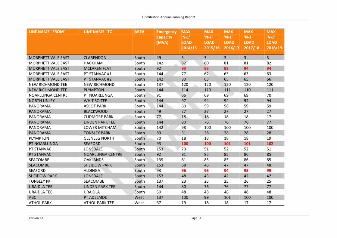
Distribution Annual Planning Report
Version 1.1 Page 31
LINE NAME "FROM" LINE NAME "TO" AREA Emergency Capacity (MVA)
MAX 'N-1' LOAD 2014/15
MAX 'N-1' LOAD 2015/16
MAX 'N-1' LOAD 2016/17
MAX 'N-1' LOAD 2017/18
MAX 'N-1' LOAD 2018/19
MORPHETT VALE EAST CLARENDON South 49 3 3 3 3 3 MORPHETT VALE EAST HACKHAM South 142 82 80 81 81 82 MORPHETT VALE EAST MCLAREN FLAT South 92 93 93 93 94 94 MORPHETT VALE EAST PT STANVAC #1 South 144 77 62 63 63 63 MORPHETT VALE EAST PT STANVAC #2 South 142 80 65 65 65 66 NEW RICHMOND TEE NEW RICHMOND South 137 120 120 120 120 120 NEW RICHMOND TEE PLYMPTON South 144 114 110 111 110 111 NOARLUNGA CENTRE PT NOARLUNGA South 91 66 69 69 69 70 NORTH UNLEY WHIT SQ TEE South 144 97 94 94 94 94 PANORAMA ASCOT PARK South 144 60 59 58 59 59 PANORAMA BLACKWOOD South 49 27 27 27 27 27 PANORAMA CUDMORE PARK South 77 18 18 18 18 17 PANORAMA LINDEN PARK TEE South 144 80 76 76 76 77 PANORAMA LOWER MITCHAM South 142 98 100 100 100 100 PANORAMA TONSLEY PARK South 89 31 28 28 28 28 PLYMPTON GLENELG NORTH South 70 18 18 18 18 19 PT NOARLUNGA SEAFORD South 93 100 100 101 101 102 PT STANVAC LONSDALE South 153 73 51 52 52 51 PT STANVAC NOARLUNGA CENTRE South 92 81 85 85 86 85 SEACOMBE OAKLANDS South 139 81 85 85 86 85 SEACOMBE SHEIDOW PARK South 153 68 46 47 47 48 SEAFORD ALDINGA South 93 96 96 94 95 95 SHEIDOW PARK LONSDALE South 153 48 43 42 42 42 TONSLEY PK SEACOMBE South 137 23 25 25 26 25 URAIDLA TEE LINDEN PARK TEE South 144 80 76 76 77 77 URAIDLA TEE URAIDLA South 50 48 48 48 48 48 ABC PT ADELAIDE West 137 100 99 101 100 100 ATHOL PARK ATHOL PARK TEE West 67 19 18 18 17 17
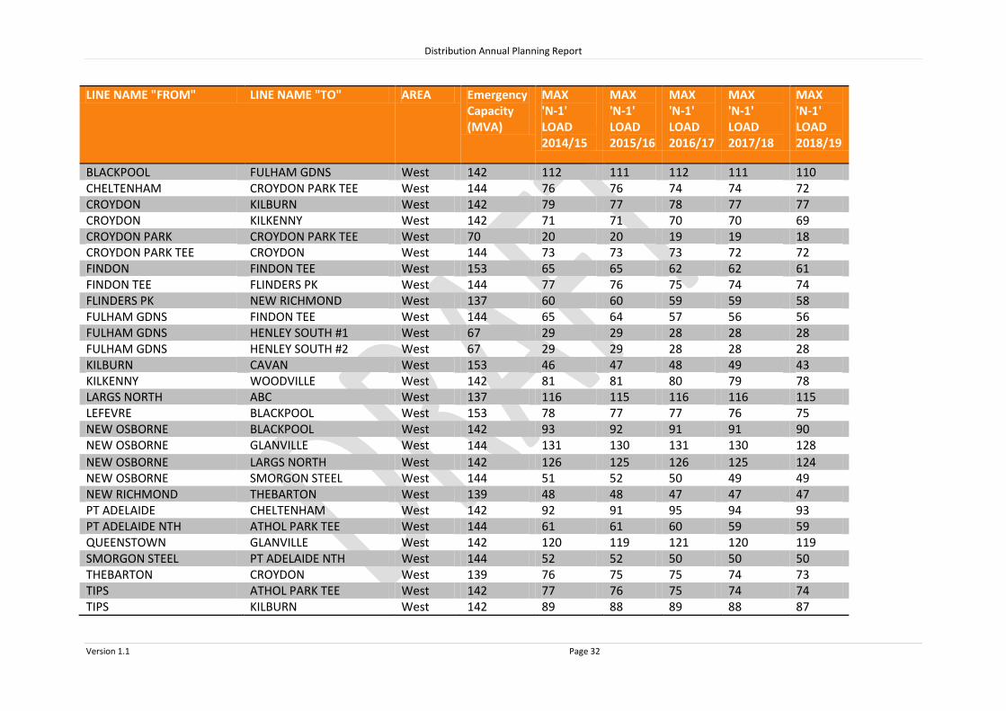
Distribution Annual Planning Report
Version 1.1 Page 32
LINE NAME "FROM" LINE NAME "TO" AREA Emergency Capacity (MVA)
MAX 'N-1' LOAD 2014/15
MAX 'N-1' LOAD 2015/16
MAX 'N-1' LOAD 2016/17
MAX 'N-1' LOAD 2017/18
MAX 'N-1' LOAD 2018/19
BLACKPOOL FULHAM GDNS West 142 112 111 112 111 110 CHELTENHAM CROYDON PARK TEE West 144 76 76 74 74 72 CROYDON KILBURN West 142 79 77 78 77 77 CROYDON KILKENNY West 142 71 71 70 70 69 CROYDON PARK CROYDON PARK TEE West 70 20 20 19 19 18 CROYDON PARK TEE CROYDON West 144 73 73 73 72 72 FINDON FINDON TEE West 153 65 65 62 62 61 FINDON TEE FLINDERS PK West 144 77 76 75 74 74 FLINDERS PK NEW RICHMOND West 137 60 60 59 59 58 FULHAM GDNS FINDON TEE West 144 65 64 57 56 56 FULHAM GDNS HENLEY SOUTH #1 West 67 29 29 28 28 28 FULHAM GDNS HENLEY SOUTH #2 West 67 29 29 28 28 28 KILBURN CAVAN West 153 46 47 48 49 43 KILKENNY WOODVILLE West 142 81 81 80 79 78 LARGS NORTH ABC West 137 116 115 116 116 115 LEFEVRE BLACKPOOL West 153 78 77 77 76 75 NEW OSBORNE BLACKPOOL West 142 93 92 91 91 90 NEW OSBORNE GLANVILLE West 144 131 130 131 130 128
NEW OSBORNE LARGS NORTH West 142 126 125 126 125 124 NEW OSBORNE SMORGON STEEL West 144 51 52 50 49 49 NEW RICHMOND THEBARTON West 139 48 48 47 47 47 PT ADELAIDE CHELTENHAM West 142 92 91 95 94 93 PT ADELAIDE NTH ATHOL PARK TEE West 144 61 61 60 59 59 QUEENSTOWN GLANVILLE West 142 120 119 121 120 119 SMORGON STEEL PT ADELAIDE NTH West 144 52 52 50 50 50 THEBARTON CROYDON West 139 76 75 75 74 73 TIPS ATHOL PARK TEE West 142 77 76 75 74 74 TIPS KILBURN West 142 89 88 89 88 87

Distribution Annual Planning Report
Version 1.1 Page 33
LINE NAME "FROM" LINE NAME "TO" AREA Emergency Capacity (MVA)
MAX 'N-1' LOAD 2014/15
MAX 'N-1' LOAD 2015/16
MAX 'N-1' LOAD 2016/17
MAX 'N-1' LOAD 2017/18
MAX 'N-1' LOAD 2018/19
WOODVILLE FINDON West 139 83 82 77 77 76 WOODVILLE QUEENSTOWN West 142 105 104 104 104 103
System Limitations: Morphett Vale East – McLaren Flat, Port Noarlunga – Seaford& Seaford - Aldinga from 2014/15

Distribution Annual Planning Report
Version 1.1 Page 34
Morphett Vale East – McLaren Flat 66kV Port Noarlunga – Seaford 66kV Seaford – Aldinga 66kV System Limitation The Morphett Vale East – McLaren Flat 66kV sub-transmission line, Port Noarlunga – Seaford 66kV sub-transmission line and Seaford – Aldinga 66kV sub-transmission line form either side of the Southern Suburbs 66kV loop which are both subject to a system limitation in the forward planning period, should either line fail/become faulted. From the summer of 2014/15, the 66kV network from Morphett Vale East to Willunga is forecasted to be overloaded at peak load times during 66kV network contingencies. Potential solutions considered to address the system limitation include:
Construction of new 66kV sub-transmission lines in the Southern Suburbs to provide alternate supply paths during a contingent event;
Non-network options to reduce the load in the Fleurieu region supplied by the 66kV sub-transmission system; or
Combination of network and non-network solutions.
Due to the extent of the overloads involved, power factor correction would not defer the system limitation. A load reduction of at least 2MVA would be required to defer this system limitation for a 12 month period.
A Request for Proposals has been published for this system limitation and further information can be found at: http://www.sapowernetworks.com.au/public/download.jsp?id=11540 and negotiations are continuing with a non-network solution provider regarding this constraint.

Distribution Annual Planning Report
Version 1.1 Page 35
8.3 Eastern Suburbs Regional Development Plan
The Eastern Suburbs
The SA Power Networks’ Eastern Suburbs includes the area from Golden Grove in the North to Linden Park in the south and extends westwards to Prospect and North Adelaide and eastwards to the Adelaide Hills. There are two main connection points in the Eastern Suburbs, being Northfield and Magill, with connections to the associated CBD system (East Tce and City West connection points) and Dry Creek power station. The forecast and loads for the Eastern Suburbs’ connection point includes the Adelaide Central Region (ACR) which covers the Adelaide CBD. The CBD system is an integral part of the Eastern Suburbs system. SA Power Network’s Distribution Network Electricity is supplied throughout the Eastern Suburbs from distribution substations supplied directly from the 66kV sub-transmission network. These substations are operated at 66,000 volts stepped down to 11,000 volts and upgraded when load exceeds capacity. Customers are supplied from SA Power Networks’ distribution system via 11kV primary distribution feeders, which are connected to distribution substations. These feeders are extended and upgraded as required to meet customer demand, customer connection requests and to maintain QoS. Large customer projects may require a distribution substation upgrade as well as 11kV feeder or 66kV line modifications. Therefore, SA Power Networks should be notified as early as possible during the planning stages of a project so that customer connection requirements can be met. There are no system limitations forecast for the primary distribution feeders under normal conditions in the Eastern Suburbs in the next two years.
8.3.1 Eastern Suburbs SCADA Substations
Source Connection Point Associated SCADA Substations
Eastern Suburbs Meshed 66kV Network:
City West – ACR
Dry Creek – Central and East
East Tce
Magill – Transformers 2 and 3 Northfield
Burnside
Campbelltown
Clearview
Glynde
Golden Grove
Harrow
Hillcrest
Holden Hill
Hope Valley
Ingle Farm
Kent Town
Kilburn South
Linden Park
North Adelaide
Northfield
Norwood
Prospect
Tea Tree Gully
Woodforde

CLEARVIEW
NORTH ADELAIDE
PROSPECTHARROW
EAST TERRACE
KENTTOWN
KILBURN SOUTH
NORTHFIELD
INGLE FARM
LINDEN PARK
NORWOOD
BURNSIDE
GLYNDE (FUTURE)
CAMPBELLTOWN
WOODFORDE
MAGILL
HILLCREST
HOLDEN HILLDRY CREEK
HOPE VALLEY
TEA TREE GULLY
GOLDEN GROVE
CBD
Legend275kV Transmission Line132kV Transmission Line66kV Sub Transmission Line33kV Sub Transmission LineSubstation
System Limitation.
0.0 0.5 1.0 1.5 2.0 2.5
Kilometres
EASTERNSUBURBS
NORTHERNSUBURBS
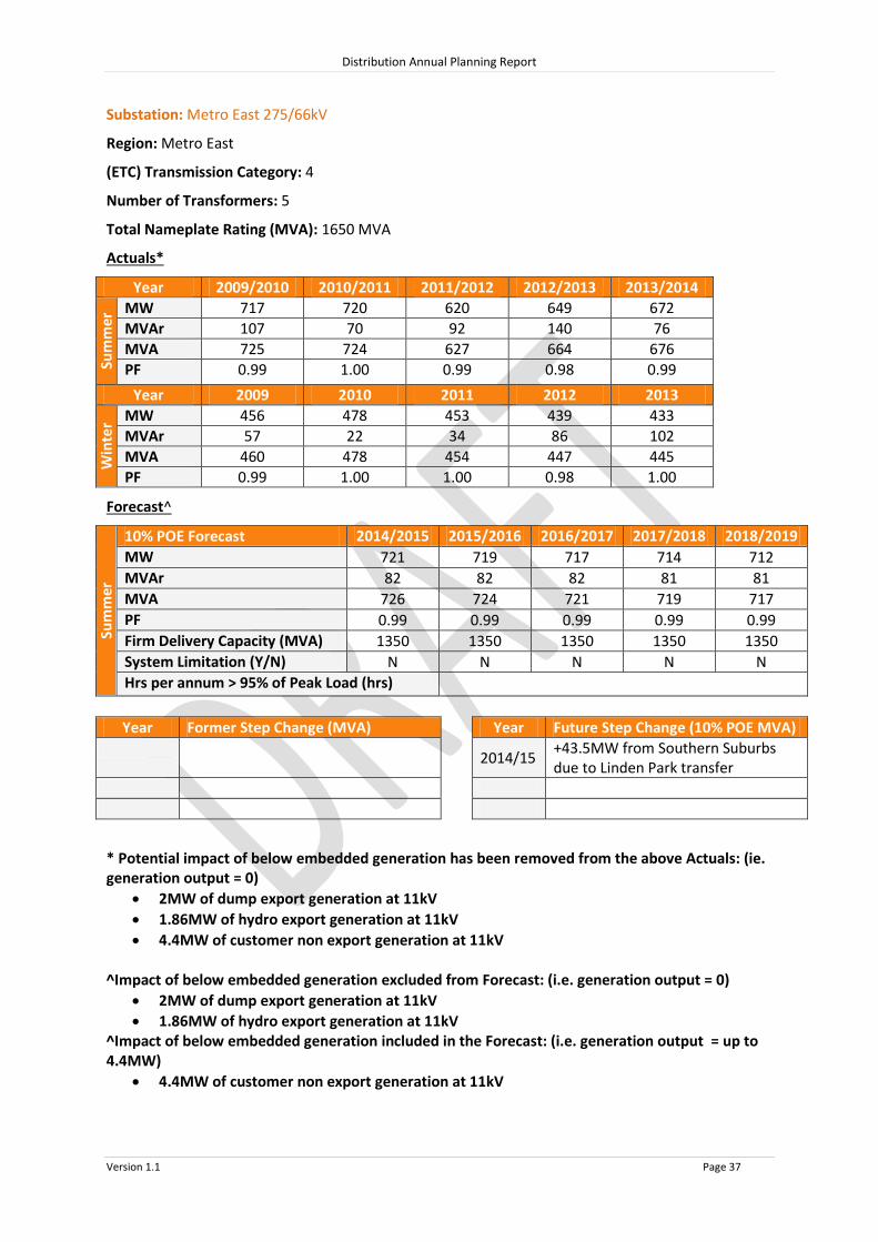
Distribution Annual Planning Report
Version 1.1 Page 37
Substation: Metro East 275/66kV
Region: Metro East
(ETC) Transmission Category: 4
Number of Transformers: 5
Total Nameplate Rating (MVA): 1650 MVA
Actuals*
Year 2009/2010 2010/2011 2011/2012 2012/2013 2013/2014
Sum
mer
MW 717 720 620 649 672
MVAr 107 70 92 140 76
MVA 725 724 627 664 676
PF 0.99 1.00 0.99 0.98 0.99
Year 2009 2010 2011 2012 2013
Win
ter MW 456 478 453 439 433
MVAr 57 22 34 86 102
MVA 460 478 454 447 445
PF 0.99 1.00 1.00 0.98 1.00
Forecast^
Sum
mer
10% POE Forecast 2014/2015 2015/2016 2016/2017 2017/2018 2018/2019
MW 721 719 717 714 712
MVAr 82 82 82 81 81
MVA 726 724 721 719 717
PF 0.99 0.99 0.99 0.99 0.99
Firm Delivery Capacity (MVA) 1350 1350 1350 1350 1350
System Limitation (Y/N) N N N N N
Hrs per annum > 95% of Peak Load (hrs)
Year Former Step Change (MVA) Year Future Step Change (10% POE MVA)
2014/15
+43.5MW from Southern Suburbs due to Linden Park transfer
* Potential impact of below embedded generation has been removed from the above Actuals: (ie. generation output = 0)
2MW of dump export generation at 11kV
1.86MW of hydro export generation at 11kV
4.4MW of customer non export generation at 11kV
^Impact of below embedded generation excluded from Forecast: (i.e. generation output = 0)
2MW of dump export generation at 11kV
1.86MW of hydro export generation at 11kV ^Impact of below embedded generation included in the Forecast: (i.e. generation output = up to 4.4MW)
4.4MW of customer non export generation at 11kV

Distribution Annual Planning Report
Version 1.1 Page 38
Substation: Burnside 66/11kV
Region: Metro East
Number of Feeders: 4
Number of Transformers: 1
Total Nameplate Rating (MVA): 25 MVA
Actuals
Year 2009/2010 2010/2011 2011/2012 2012/2013 2013/2014
Sum
mer
MW 11.0 12.4 9.7 12.1 13.4
MVAr 5.3 5.8 4.4 4.0 4.0
MVA 12.3 13.7 10.6 12.8 13.9
PF 0.90 0.91 0.91 0.95 0.96
Year 2009 2010 2011 2012 2013
Win
ter MW 8.7 9.4 8.7 9.3 9.7
MVAr 3.7 3.8 3.7 2.7 2.4
MVA 9.5 10.1 9.4 9.7 10.0
PF 0.92 0.93 0.92 0.96 0.97
Forecast
Sum
mer
10% POE Forecast 2014/2015 2015/2016 2016/2017 2017/2018 2018/2019
MW 12.9 13.0 13.0 13.1 13.1
MVAr 4.7 4.7 4.8 4.8 4.8
MVA 13.8 13.8 13.9 13.9 14.0
PF 0.94 0.94 0.94 0.94 0.94
Total Capacity (MVA) 31.2 31.2 31.2 31.2 31.2
50% POE Forecast
MW 11.2 11.2 11.3 11.3 11.3
MVAr 4.1 4.1 4.1 4.1 4.1
MVA 12.0
12.0
12.0
12.0
12.0 PF 0.94 0.94 0.94 0.94 0.94
Firm Delivery Capacity (MVA) 0.0 0.0 0.0 0.0 0.0
Transfer Capacity (MVA) 13.7
13.6
13.4
13.3
13.2 System Limitation (Y/N) N N N N N
Hrs per annum > 95% of Peak Load (hrs) 6
Year Former Step Change (MVA) Year Future Step Change (10% POE MVA)
2012/13 +0.9MVA Customer Load Increase
+1.8MVA from Woodforde

Distribution Annual Planning Report
Version 1.1 Page 39
Substation: Campbelltown 66/11kV
Region: Metro East
Number of Feeders: 7
Number of Transformers: 2
Total Nameplate Rating (MVA): 48 MVA
Actuals
Year 2009/2010 2010/2011 2011/2012 2012/2013 2013/2014
Sum
mer
MW 46.8 52.6 42.6 44.7 47.1
MVAr 19.3 21.1 15.0 15.4 14.6
MVA 50.6 56.7 45.1 47.3 49.3
PF 0.93 0.93 0.94 0.95 0.96
Year 2009 2010 2011 2012 2013
Win
ter MW 30.5 31.7 26.7 32.0 30.1
MVAr 9.0 8.9 8.2 7.6 6.5
MVA 31.8 33.0 27.9 32.9 30.8
PF 0.96 0.96 0.96 0.97 0.98
Forecast
Sum
mer
10% POE Forecast 2014/2015 2015/2016 2016/2017 2017/2018 2018/2019
MW 49.3 50.0 50.7 44.4 45.0
MVAr 16.6 16.8 17.1 12.9 13.1
MVA 52.0 52.8 53.5 46.2 46.9
PF 0.95 0.95 0.95 0.96 0.96
Total Capacity (MVA) 49.3 50.0 50.7 57.8 57.8
50% POE Forecast
MW 43.1 43.7 44.4 38.2 38.9
MVAr 14.5 14.7 14.9 11.1 11.3
MVA 45.5 46.1 46.9 39.8 40.5
PF 0.95 0.95 0.95 0.96 0.96
Firm Delivery Capacity (MVA) 30.5 30.5 30.5 30.5 30.5
Transfer Capacity (MVA) 13.2 13.0 12.8 12.6 12.4
System Limitation (Y/N) Y* Y* Y^ N N
Hrs per annum > 95% of Peak Load (hrs) 7
Year Former Step Change (MVA) Year Future Step Change (10% POE MVA)
2010/11 +1.4MVA from Woodforde 2017/18 -8.0MVA to Glynde
2013/14 -0.9MVA to Woodforde
*Within planning criteria risk margin
^Solved by transfer to Glynde in 2017/18

Distribution Annual Planning Report
Version 1.1 Page 40
Substation: Clearview 66/11kV
Region: Metro East
Number of Feeders: 4
Number of Transformers: 2
Total Nameplate Rating (MVA): 20 MVA
Actuals
Year 2009/2010 2010/2011 2011/2012 2012/2013 2013/2014
Sum
mer
MW 24.1 21.2 17.7 18.5 21.0
MVAr 8.8 7.2 5.7 5.8 6.2
MVA 25.7 22.4 18.6 19.4 21.9
PF 0.94 0.95 0.95 0.95 0.96
Year 2009 2010 2011 2012 2013
Win
ter MW 17.6 16.5 15.0 14.7 13.6
MVAr 4.9 3.8 3.4 2.9 2.6
MVA 18.3 16.9 15.4 15.0 13.8
PF 0.96 0.98 0.98 0.98 0.98
Forecast
Sum
mer
10% POE Forecast 2014/2015 2015/2016 2016/2017 2017/2018 2018/2019
MW 21.1 21.2 21.3 21.4 21.5
MVAr 6.6 6.6 6.6 6.6 6.7
MVA 22.1 22.2 22.3 22.4 22.5
PF 0.95 0.95 0.95 0.95 0.95
Total Capacity (MVA) 26.6 26.6 26.6 26.6 26.6
50% POE Forecast
MW 18.3 18.4 18.5 18.6 18.7
MVAr 5.7 5.7 5.8 5.8 5.8
MVA 19.2
19.3
19.4
19.5
19.6 PF 0.95 0.95 0.95 0.95 0.95
Firm Delivery Capacity (MVA) 15.0 15.0 15.0 15.0 15.0
Transfer Capacity (MVA) 17.2
17.0
16.9
16.7
16.5 System Limitation (Y/N) N N N N N
Hrs per annum > 95% of Peak Load (hrs) 7
Year Former Step Change (MVA) Year Future Step Change (10% POE MVA)
2009/10 -1.5MVA to Northfield
2010/11 -2.4MVA to Hillcrest

Distribution Annual Planning Report
Version 1.1 Page 41
Substation: Glynde 66/11kV
Region: Metro East
Number of Feeders: 3
Number of Transformers: 1
Total Nameplate Rating (MVA): 32 MVA
Actuals
Year 2009/2010 2010/2011 2011/2012 2012/2013 2013/2014
Sum
mer
MW N/A N/A N/A N/A N/A
MVAr N/A N/A N/A N/A N/A
MVA N/A N/A N/A N/A N/A
PF N/A N/A N/A N/A N/A
Year 2009 2010 2011 2012 2013
Win
ter MW N/A N/A N/A N/A N/A
MVAr N/A N/A N/A N/A N/A
MVA N/A N/A N/A N/A N/A
PF N/A N/A N/A N/A N/A
Forecast
Sum
mer
10% POE Forecast 2014/2015 2015/2016 2016/2017 2017/2018 2018/2019
MW N/A N/A N/A 18.2 18.4
MVAr N/A N/A N/A 6.0 6.0
MVA N/A N/A N/A 19.2 19.4
PF N/A N/A N/A 0.95 0.95
Total Capacity (MVA) N/A N/A N/A 36.2 36.2
50% POE Forecast
MW N/A N/A N/A 17.3 17.4
MVAr N/A N/A N/A 5.7 5.7
MVA N/A N/A N/A 18.2 18.4
PF N/A N/A N/A 0.95 0.95
Firm Delivery Capacity (MVA) N/A N/A N/A 0 0
Transfer Capacity (MVA) N/A N/A N/A 20.0 19.8
System Limitation (Y/N) N/A N/A N/A N N
Hrs per annum > 95% of Peak Load (hrs) 7
Year Former Step Change (MVA) Year Future Step Change (10% POE MVA)
2017/18 +6.2MVA from Norwood
+8.0MVA from Campbelltown
+5.0MVA from Woodforde
*Within planning criteria risk margin

Distribution Annual Planning Report
Version 1.1 Page 42
Substation: Golden Grove 66/11kV
Region: Metro East
Number of Feeders: 9
Number of Transformers: 3
Total Nameplate Rating (MVA): 75 MVA
Actuals
Year 2009/2010 2010/2011 2011/2012 2012/2013 2013/2014
Sum
mer
MW 44.1 44.2 40.1 40.9 44.5
MVAr 16.8 15.5 13.7 16.2 13.3
MVA 47.2 46.9 42.4 44.0 46.4
PF 0.94 0.94 0.95 0.93 0.96
Year 2009 2010 2011 2012 2013
Win
ter MW 32.4 34.9 32.4 33.5 31.9
MVAr 8.7 9.2 8.2 7.6 6.9
MVA 33.5 36.1 33.4 34.4 32.6
PF 0.97 0.97 0.97 0.98 0.98
Forecast
Sum
mer
10% POE Forecast 2014/2015 2015/2016 2016/2017 2017/2018 2018/2019
MW 46.1 46.1 46.1 46.1 46.2
MVAr 15.0 15.0 15.0 15.0 15.0
MVA 48.5 48.5 48.5 48.5 48.6
PF 0.95 0.95 0.95 0.95 0.95
Total Capacity (MVA) 84.6 84.6 84.6 84.6 84.6
50% POE Forecast
MW 41.1 41.1 41.1 41.2 41.2
MVAr 13.4 13.4 13.4 13.4 13.4
MVA 43.2
43.3
43.3
43.3
43.4 PF 0.95 0.95 0.95 0.95 0.95
Firm Delivery Capacity (MVA) 59.6 59.6 59.6 59.6 59.6
Transfer Capacity (MVA) 11.5
11.4
11.3
11.3
11.2 System Limitation (Y/N) N N N N N
Hrs per annum > 95% of Peak Load (hrs) 6
Year Former Step Change (MVA) Year Future Step Change (10% POE MVA)
2009/10 +0.7MVA Customer load increase

Distribution Annual Planning Report
Version 1.1 Page 43
Substation: Harrow 66/11kV
Region: Metro East
Number of Feeders: 4
Number of Transformers: 2
Total Nameplate Rating (MVA): 20 MVA
Actuals
Year 2009/2010 2010/2011 2011/2012 2012/2013 2013/2014
Sum
mer
MW 22.6 23.0 19.3 16.4 19.3
MVAr 10.3 9.2 7.6 6.2 6.7
MVA 24.8 24.7 20.8 17.5 20.4
PF 0.91 0.93 0.93 0.93 0.95
Year 2009 2010 2011 2012 2013
Win
ter MW 19.4 17.3 17.2 15.4 13.5
MVAr 6.6 5.3 5.0 4.5 3.0
MVA 20.5 18.1 17.9 16.1 13.8
PF 0.95 0.96 0.96 0.96 0.98
Forecast
Sum
mer
10% POE Forecast 2014/2015 2015/2016 2016/2017 2017/2018 2018/2019
MW 18.6 18.7 18.8 18.8 18.9
MVAr 6.9 6.9 6.9 7.0 7.0
MVA 19.9 19.9 20.0 20.1 20.1
PF 0.94 0.94 0.94 0.94 0.94
Total Capacity (MVA) 28.3 28.3 28.3 28.3 28.3
50% POE Forecast
MW 16.3 16.4 16.5 16.6 16.7
MVAr 6.0 6.0 6.1 6.1 6.2
MVA 17.4
17.5
17.6
17.7
17.8 PF 0.94 0.94 0.94 0.94 0.94
Firm Delivery Capacity (MVA) 15.0 15.0 15.0 15.0 15.0
Transfer Capacity (MVA) 12.5
12.3
12.2
12.1
11.9 System Limitation (Y/N) N N N N N
Hrs per annum > 95% of Peak Load (hrs) 6
Year Former Step Change (MVA) Year Future Step Change (10% POE MVA)
2009/10 -1.9MVA to Norwood
+2.0MVA from North Adelaide
+0.5MVA from Norwood
-0.7MVA to Hillcrest
+0.5MVA Customer load increase
2010/11 -1.5MVA to Norwood
2012/13 -2.0MVA to North Adelaide
-1.1MVA to Hillcrest

Distribution Annual Planning Report
Version 1.1 Page 44
Substation: Hillcrest 66/11kV
Region: Metro East
Number of Feeders: 6
Number of Transformers: 2
Total Nameplate Rating (MVA): 50 MVA
Actuals
Year 2009/2010 2010/2011 2011/2012 2012/2013 2013/2014
Sum
mer
MW 30.5 32.7 28.1 31.0 33.8
MVAr 12.0 10.8 11.3 10.5 10.8
MVA 32.8 34.5 30.3 32.7 35.5
PF 0.93 0.95 0.93 0.95 0.95
Year 2009 2010 2011 2012 2013
Win
ter MW 17.8 21.9 27.8 22.2 22.5
MVAr 6.6 6.6 7.4 6.0 5.3
MVA 19.0 22.9 28.7 23.0 23.1
PF 0.94 0.96 0.97 0.97 0.97
Forecast
Sum
mer
10% POE Forecast 2014/2015 2015/2016 2016/2017 2017/2018 2018/2019
MW 35.3 35.4 35.5 35.6 35.7
MVAr 11.9 11.9 12.0 12.0 12.0
MVA 37.2 37.3 37.4 37.5 37.7
PF 0.95 0.95 0.95 0.95 0.95
Total Capacity (MVA) 61.7 61.7 61.7 61.7 61.7
50% POE Forecast
MW 31.5 31.5 31.6 31.7 31.7
MVAr 10.6 10.6 10.7 10.7 10.7
MVA 33.2
33.3
33.4
33.4
33.5 PF 0.95 0.95 0.95 0.95 0.95
Firm Delivery Capacity (MVA) 36.8 36.8 36.8 36.8 36.8
Transfer Capacity (MVA) 7.1
7.1
7.0
7.0
6.9 System Limitation (Y/N) N N N N N
Hrs per annum > 95% of Peak Load (hrs) 7
Year Former Step Change (MVA) Year Future Step Change (10% POE MVA)
2009/10 +0.7MVA from Harrow
+4.0MVA from Northfield
+0.4MVA Customer load increase
2010/11 +1.4MVA from Northfield
+2.4MVA from Clearview
2012/13 +1.1 from Harrow

Distribution Annual Planning Report
Version 1.1 Page 45
Substation: Holden Hill 66/11kV
Region: Metro East
Number of Feeders: 7
Number of Transformers: 2
Total Nameplate Rating (MVA): 42 MVA
Actuals
Year 2009/2010 2010/2011 2011/2012 2012/2013 2013/2014
Sum
mer
MW 37.7 38.6 32.0 34.4 36.1
MVAr 15.4 13.9 12.4 11.9 11.0
MVA 40.8 41.1 34.3 36.4 37.8
PF 0.93 0.94 0.93 0.95 0.96
Year 2009 2010 2011 2012 2013
Win
ter MW 27.3 25.9 27.7 26.0 22.5
MVAr 9.6 7.1 6.7 6.0 5.9
MVA 28.9 26.8 28.5 26.6 23.3
PF 0.94 0.96 0.97 0.97 0.97
Forecast
Sum
mer
10% POE Forecast 2014/2015 2015/2016 2016/2017 2017/2018 2018/2019
MW 37.1 37.2 37.4 37.5 37.6
MVAr 12.9 12.9 13.0 13.0 13.0
MVA 39.3 39.4 39.5 39.7 39.8
PF 0.94 0.94 0.94 0.94 0.94
Total Capacity (MVA) 46.7 46.7 46.7 46.7 46.7
50% POE Forecast
MW 33.3 33.3 33.4 33.5 33.6
MVAr 11.5 11.6 11.6 11.6 11.7
MVA 35.2
35.3
35.4
35.5
35.6 PF 0.94 0.94 0.94 0.94 0.94
Firm Delivery Capacity (MVA) 25.0 25.0 25.0 25.0 25.0
Transfer Capacity (MVA) 20.2
20.0
19.8
19.6
19.5 System Limitation (Y/N) N N N N N
Hrs per annum > 95% of Peak Load (hrs) 7
Year Former Step Change (MVA) Year Future Step Change (10% POE MVA)
2011/12 +1.0MVA from Hope Valley

Distribution Annual Planning Report
Version 1.1 Page 46
Substation: Hope Valley 66/11kV
Region: Metro East
Number of Feeders: 3
Number of Transformers: 1
Total Nameplate Rating (MVA): 25 MVA
Actuals*
Year 2009/2010 2010/2011 2011/2012 2012/2013 2013/2014
Sum
mer
MW 18.7 20.2 16.2 16.5 18.5
MVAr 6.9 8.0 5.8 6.3 5.8
MVA 19.9 21.8 17.2 17.7 19.4
PF 0.94 0.93 0.94 0.94 0.95
Year 2009 2010 2011 2012 2013
Win
ter MW 12.4 13.9 14.2 13.2 13.0
MVAr 3.1 3.9 3.4 2.7 2.9
MVA 12.8 14.5 14.6 13.4 13.4
PF 0.97 0.96 0.97 0.98 0.98
Forecast*
Sum
mer
10% POE Forecast 2014/2015 2015/2016 2016/2017 2017/2018 2018/2019
MW 19.0 18.9 18.8 18.6 18.5
MVAr 6.5 6.4 6.4 6.4 6.3
MVA 20.1 20.0 19.8 19.7 19.6
PF 0.95 0.95 0.95 0.95 0.95
Total Capacity (MVA) 31.2 31.2 31.2 31.2 31.2
50% POE Forecast
MW 16.6 16.5 16.4 16.3 16.2
MVAr 5.7 5.6 5.6 5.6 5.5
MVA 17.5
17.4
17.3
17.2
17.1 PF 0.95 0.95 0.95 0.95 0.95
Firm Delivery Capacity (MVA) 0.0 0.0 0.0 0.0 0.0
Transfer Capacity (MVA) 16.0
16.0
16.0
16.1
16.1 System Limitation (Y/N) Y* Y* Y* Y* Y*
Hrs per annum > 95% of Peak Load (hrs) 5
Year Former Step Change (MVA) Year Future Step Change (10% POE MVA)
* Potential impact of below embedded generation has been removed from the above Actuals & excluded from Forecast: (ie. generation output = 0)
2MW of dump export generation at 11kV
1.86MW of hydro export generation at 11kV

Distribution Annual Planning Report
Version 1.1 Page 47
Substation: Ingle Farm 66/11kV
Region: Metro East
Number of Feeders: 6
Number of Transformers: 2
Total Nameplate Rating (MVA): 42 MVA
Actuals
Year 2009/2010 2010/2011 2011/2012 2012/2013 2013/2014
Sum
mer
MW 38.9 40.1 33.0 33.7 35.3
MVAr 15.8 16.2 14.2 12.0 11.2
MVA 42.0 43.2 36.0 35.8 37.0
PF 0.93 0.93 0.92 0.94 0.95
Year 2009 2010 2011 2012 2013
Win
ter MW 26.5 26.9 25.0 23.0 23.2
MVAr 8.0 6.9 6.6 5.3 4.6
MVA 27.7 27.8 25.8 23.6 23.6
PF 0.96 0.97 0.97 0.97 0.98
Forecast
Sum
mer
10% POE Forecast 2014/2015 2015/2016 2016/2017 2017/2018 2018/2019
MW 36.0 36.1 36.1 36.1 36.2
MVAr 13.4 13.4 13.4 13.4 13.4
MVA 38.4 38.5 38.5 38.5 38.6
PF 0.94 0.94 0.94 0.94 0.94
Total Capacity (MVA) 51.7 51.7 51.7 51.7 51.7
50% POE Forecast
MW 32.4 32.5 32.5 32.6 32.7
MVAr 12.0 12.1 12.1 12.1 12.1
MVA 34.6
34.6
34.7
34.8
34.8 PF 0.94 0.94 0.94 0.94 0.94
Firm Delivery Capacity (MVA) 26.0 26.0 26.0 26.0 26.0
Transfer Capacity (MVA) 14.4
14.3
14.2
14.0
13.9 System Limitation (Y/N) N N N N N
Hrs per annum > 95% of Peak Load (hrs) 7
Year Former Step Change (MVA) Year Future Step Change (10% POE MVA)
2010/11 -1.9MVA to Salisbury

Distribution Annual Planning Report
Version 1.1 Page 48
Substation: Kent Town 66/11kV
Region: Metro East
Number of Feeders: 5
Number of Transformers: 2
Total Nameplate Rating (MVA): 50 MVA
Actuals
Year 2009/2010 2010/2011 2011/2012 2012/2013 2013/2014
Sum
mer
MW 37.1 37.2 30.7 32.8 32.2
MVAr 16.1 16.5 15.1 14.8 14.0
MVA 40.4 40.7 34.2 36.0 35.1
PF 0.92 0.91 0.90 0.91 0.92
Year 2009 2010 2011 2012 2013
Win
ter MW 22.6 23.7 24.8 21.1 21.6
MVAr 7.8 8.4 9.9 8.6 7.9
MVA 23.9 25.2 26.7 22.8 23.0
PF 0.95 0.94 0.93 0.93 0.94
Forecast
Sum
mer
10% POE Forecast 2014/2015 2015/2016 2016/2017 2017/2018 2018/2019
MW 33.9 34.1 34.3 34.6 34.8
MVAr 15.6 15.7 15.8 15.9 16.0
MVA 37.3 37.5 37.8 38.1 38.3
PF 0.91 0.91 0.91 0.91 0.91
Total Capacity (MVA) 59.0 59.0 59.0 59.0 59.0
50% POE Forecast
MW 30.1 30.2 30.2 30.3 30.4
MVAr 13.8 13.9 13.9 13.9 14.0
MVA 33.1
33.2
33.3
33.3
33.4 PF 0.91 0.91 0.91 0.91 0.91
Firm Delivery Capacity (MVA) 29.8 29.8 29.8 29.8 29.8
Transfer Capacity (MVA) 21.7
21.6
21.4
21.2
21.0 System Limitation (Y/N) N N N N N
Hrs per annum > 95% of Peak Load (hrs) 9
Year Former Step Change (MVA) Year Future Step Change (10% POE MVA)
2011/12 -1.4MVA to Linden Park
2013/14 -1.3MVA to Norwood

Distribution Annual Planning Report
Version 1.1 Page 49
Substation: Kilburn South 66/11kV
Region: Metro East
Number of Feeders: 4
Number of Transformers: 1
Total Nameplate Rating (MVA): 32 MVA
Actuals
Year 2009/2010 2010/2011 2011/2012 2012/2013 2013/2014
Sum
mer
MW 12.5 12.8 10.5 11.1 11.6
MVAr 5.4 5.4 4.5 1.2 1.2
MVA 13.6 13.9 11.4 11.2 11.7
PF 0.92 0.92 0.92 1.00 0.99
Year 2009 2010 2011 2012 2013
Win
ter MW 8.8 9.5 8.8 8.4 8.5
MVAr 3.4 2.7 2.7 2.5 0.8
MVA 9.5 9.8 9.2 8.8 8.5
PF 0.93 0.96 0.96 0.96 1.00
Forecast
Sum
mer
10% POE Forecast 2014/2015 2015/2016 2016/2017 2017/2018 2018/2019
MW 12.5 12.4 12.4 12.3 12.2
MVAr 1.3 1.3 1.3 1.3 1.3
MVA 12.5 12.5 12.4 12.4 12.3
PF 0.99 0.99 0.99 0.99 0.99
Total Capacity (MVA) 36.4 36.4 36.4 36.4 36.4
50% POE Forecast
MW 11.3 11.2 11.1 11.1 11.0
MVAr 1.2 1.2 1.2 1.2 1.2
MVA 11.3
11.3
11.2
11.1
11.1 PF 0.99 0.99 0.99 0.99 0.99
Firm Delivery Capacity (MVA) 0.0 0.0 0.0 0.0 0.0
Transfer Capacity (MVA) 10.1
10.2
10.2
10.3
10.3 System Limitation (Y/N) Y* Y* Y* Y* Y*
Hrs per annum > 95% of Peak Load (hrs) 7
Year Former Step Change (MVA) Year Future Step Change (10% POE MVA)
2009/10 +1.2MVA from Prospect 2014/15 +1.7MVA from Prospect
2012/13 6.0MVAr Capacitor bank installed
2013/14 +1.4MVA customer load increase
*Within planning criteria risk margin

Distribution Annual Planning Report
Version 1.1 Page 50
Substation: Linden Park 66/11kV
Region: Metro East
Number of Feeders: 7
Number of Transformers: 2
Total Nameplate Rating (MVA): 50 MVA
Actuals
Year 2009/2010 2010/2011 2011/2012 2012/2013 2013/2014
Sum
mer
MW 37.5 37.2 34.9 36.6 38.9
MVAr 16.6 15.2 13.4 14.5 14.2
MVA 41.0 40.2 37.4 39.4 41.4
PF 0.92 0.93 0.93 0.93 0.94
Year 2009 2010 2011 2012 2013
Win
ter MW 25.7 33.1 24.2 28.3 26.9
MVAr 9.1 11.0 7.7 8.4 7.0
MVA 27.2 34.9 25.4 29.5 27.8
PF 0.94 0.95 0.95 0.96 0.97
Forecast
Sum
mer
10% POE Forecast 2014/2015 2015/2016 2016/2017 2017/2018 2018/2019
MW 38.0 38.0 38.0 37.9 37.8
MVAr 14.6 14.6 14.6 14.6 14.5
MVA 40.7 40.7 40.7 40.6 40.5
PF 0.93 0.93 0.93 0.93 0.93
Total Capacity (MVA) 55.7 55.7 55.7 55.7 55.7
50% POE Forecast
MW 32.7 32.6 32.5 32.3 32.2
MVAr 12.6 12.5 12.5 12.4 12.4
MVA 35.0
34.9
34.8
34.6
34.5 PF 0.93 0.93 0.93 0.93 0.93
Firm Delivery Capacity (MVA) 30.5 30.5 30.5 30.5 30.5
Transfer Capacity (MVA) 15.0
15.2
15.5
15.7
15.9 System Limitation (Y/N) N N N N N
Hrs per annum > 95% of Peak Load (hrs) 7
Year Former Step Change (MVA) Year Future Step Change (10% POE MVA)
2011/12 +1.6MVA Customer load increase
+1.4MVA from Kent Town
+2.9MVA from Kingswood

Distribution Annual Planning Report
Version 1.1 Page 51
Substation: North Adelaide 66/11kV
Region: Metro East
Number of Feeders: 7
Number of Transformers: 2
Total Nameplate Rating (MVA): 64 MVA
Actuals
Year 2009/2010 2010/2011 2011/2012 2012/2013 2013/2014
Sum
mer
MW 20.8 21.7 20.4 23.7 23.7
MVAr 13.1 4.1 2.9 1.0 1.5
MVA 24.6 22.1 20.6 23.7 23.7
PF 0.85 0.98 0.99 1.00 1.00
Year 2009 2010 2011 2012 2013
Win
ter MW 14.2 14.2 12.6 13.5 16.2
MVAr 6.0 5.9 5.1 4.7 5.2
MVA 15.5 15.4 13.6 14.2 17.0
PF 0.92 0.92 0.93 0.94 0.95
Forecast
Sum
mer
10% POE Forecast 2014/2015 2015/2016 2016/2017 2017/2018 2018/2019
MW 24.8 24.6 24.5 24.3 24.2
MVAr 1.6 1.6 1.5 1.5 1.5
MVA 24.8 24.7 24.5 24.4 24.2
PF 1.00 1.00 1.00 1.00 1.00
Total Capacity (MVA) 71.9 71.9 71.9 71.9 71.9
50% POE Forecast
MW 22.3 22.2 22.0 21.9 21.8
MVAr 1.4 1.4 1.4 1.4 1.4
MVA 22.3 22.2 22.1 21.9 21.8
PF 1.00 1.00 1.00 1.00 1.00
Firm Delivery Capacity (MVA) 38.1 38.1 38.1 38.1 38.1
Transfer Capacity (MVA) 4.5
4.5
4.6
4.6
4.6 System Limitation (Y/N) N N N N N
Hrs per annum > 95% of Peak Load (hrs) 7
Year Former Step Change (MVA) Year Future Step Change (10% POE MVA)
2009/10 -2.0MVA to Harrow
2011/12 9.0MVAr Capacitor bank installed
2012/13 +2.0MVA from Harrow
+4.7MVA from Prospect

Distribution Annual Planning Report
Version 1.1 Page 52
Substation: Northfield 66/11kV
Region: Metro East
Number of Feeders: 4
Number of Transformers: 2
Total Nameplate Rating (MVA): 20 MVA
Actuals
Year 2009/2010 2010/2011 2011/2012 2012/2013 2013/2014
Sum
mer
MW 17.0 19.0 16.1 16.8 18.5
MVAr 6.6 7.6 7.0 7.0 7.1
MVA 18.2 20.4 17.6 18.2 19.8
PF 0.93 0.93 0.92 0.92 0.93
Year 2009 2010 2011 2012 2013
Win
ter MW 18.6 12.8 12.3 13.0 12.5
MVAr 6.4 4.4 3.8 4.1 3.0
MVA 19.6 13.5 12.9 13.6 12.9
PF 0.95 0.95 0.96 0.96 0.97
Forecast
Sum
mer
10% POE Forecast 2014/2015 2015/2016 2016/2017 2017/2018 2018/2019
MW 18.8 18.5 18.3 18.1 17.9
MVAr 7.7 7.6 7.5 7.5 7.4
MVA 20.3 20.1 19.8 19.6 19.3
PF 0.92 0.92 0.92 0.92 0.92
Total Capacity (MVA) 26.5 26.5 26.5 26.5 26.5
50% POE Forecast
MW 16.6 16.4 16.2 16.0 15.9
MVAr 6.8 6.8 6.7 6.6 6.5
MVA 17.9
17.8
17.5
17.3
17.2 PF 0.92 0.92 0.92 0.92 0.92
Firm Delivery Capacity (MVA) 15.0 15.0 15.0 15.0 15.0
Transfer Capacity (MVA) 19.0
19.1
19.2
19.3
19.4 System Limitation (Y/N) N N N N N
Hrs per annum > 95% of Peak Load (hrs) 7
Year Former Step Change (MVA) Year Future Step Change (10% POE MVA)
2009/10 +1.5MVA from Clearview
-4.0MVA to Hillcrest
2010/11 +2.3MVA from Cavan
-1.4MVA to Hillcrest
2011/12 +1.0MVA Customer load increase

Distribution Annual Planning Report
Version 1.1 Page 53
Substation: Norwood 66/11kV
Region: Metro East
Number of Feeders: 10
Number of Transformers: 3
Total Nameplate Rating (MVA): 63 MVA
Actuals
Year 2009/2010 2010/2011 2011/2012 2012/2013 2013/2014
Sum
mer
MW 57.6 58.2 47.3 52.0 55.8
MVAr 11.9 11.1 5.8 8.0 7.6
MVA 58.8 59.3 47.7 52.6 56.3
PF 0.98 0.98 0.99 0.99 0.99
Year 2009 2010 2011 2012 2013
Win
ter MW 38.9 42.1 38.4 39.4 38.5
MVAr 5.7 6.6 4.6 5.0 4.4
MVA 39.3 42.6 38.7 39.7 38.7
PF 0.99 0.99 0.99 0.99 0.99
Forecast
Sum
mer
10% POE Forecast 2014/2015 2015/2016 2016/2017 2017/2018 2018/2019
MW 57.2 57.0 56.8 50.5 50.4
MVAr 8.0 8.0 8.0 6.9 6.9
MVA 57.8 57.6 57.4 51.0 50.8
PF 0.99 0.99 0.99 0.99 0.99
Total Capacity (MVA) 73.8 73.8 73.8 73.8 73.8
50% POE Forecast
MW 50.1 49.9 49.7 43.9 43.8
MVAr 7.0 7.0 7.0 6.0 6.0
MVA 50.6 50.4 50.2 44.3 44.2
PF 0.99 0.99 0.99 0.99 0.99
Firm Delivery Capacity (MVA) 51.4 51.4 51.4 51.4 51.4
Transfer Capacity (MVA) 24.2
24.2
24.2
24.2
24.2 System Limitation (Y/N) N N N N N
Hrs per annum > 95% of Peak Load (hrs) 7
Year Former Step Change (MVA) Year Future Step Change (10% POE MVA)
2009/10 +1.9MVA from Harrow 2017/18 -6.2MVA to Glynde
-0.5MVA to Harrow
2010/11 +1.5MVA from Harrow
2013/14 +1.3MVA from Kent Town

Distribution Annual Planning Report
Version 1.1 Page 54
Substation: Prospect 66/11kV
Region: Metro East
Number of Feeders: 7
Number of Transformers: 2
Total Nameplate Rating (MVA): 42 MVA
Actuals*
Year 2009/2010 2010/2011 2011/2012 2012/2013 2013/2014
Sum
mer
MW 38.2 38.5 32.7 29.6 33.2
MVAr 19.3 18.8 15.6 16.1 13.0
MVA 42.8 42.9 36.2 33.7 33.6
PF 0.89 0.90 0.90 0.88 0.92
Year 2009 2010 2011 2012 2013
Win
ter MW 24.7 26.1 25.3 25.8 23.0
MVAr 9.0 11.5 10.7 8.4 6.9
MVA 26.3 28.5 27.4 27.1 24.0
PF 0.94 0.92 0.92 0.95 0.96
Forecast^
Sum
mer
10% POE Forecast 2014/2015 2015/2016 2016/2017 2017/2018 2018/2019
MW 29.8 29.4 29.0 28.6 28.2
MVAr 13.7 13.5 13.3 13.1 13.0
MVA 32.8 32.4 31.9 31.5 31.0
PF 0.91 0.91 0.91 0.91 0.91
Total Capacity (MVA) 49.4 49.4 49.4 49.4 49.4
50% POE Forecast
MW 26.7 26.5 26.2 26.0 25.9
MVAr 12.2 12.2 12.0 12.0 11.9
MVA 29.3
29.1
28.9
28.7
28.5 PF 0.91 0.91 0.91 0.91 0.91
Firm Delivery Capacity (MVA) 26.2 26.2 26.2 26.2 26.2
Transfer Capacity (MVA) 12.6
12.7
12.8
12.9
13.0 System Limitation (Y/N) N N N N N
Hrs per annum > 95% of Peak Load (hrs) 9
Year Former Step Change (MVA) Year Future Step Change (10% POE MVA)
2009/10 -1.2MVA to Kilburn South 2014/15 -1.7MVA to Kilburn South
2012/13 -4.7MVA to North Adelaide
* Impact of below embedded generation removed from Actuals: (i.e. generation output = 0)
4.4MW of customer non export embedded generation
^Impact of below embedded generation included in the Forecast: (i.e. generation output = up to 4.4MW)
4.4MW of customer non export embedded generation

Distribution Annual Planning Report
Version 1.1 Page 55
Substation: Tea Tree Gully 66/11kV
Region: Metro East
Number of Feeders: 5
Number of Transformers: 2
Total Nameplate Rating (MVA): 42 MVA
Actuals
Year 2009/2010 2010/2011 2011/2012 2012/2013 2013/2014
Sum
mer
MW 33.0 33.4 27.6 31.4 33.0
MVAr 12.3 11.8 10.0 9.9 9.9
MVA 35.2 35.4 29.4 33.0 34.5
PF 0.94 0.94 0.94 0.95 0.96
Year 2009 2010 2011 2012 2013
Win
ter MW 23.8 24.8 23.5 22.5 21.7
MVAr 6.3 6.7 5.7 5.1 4.7
MVA 24.7 25.7 24.2 23.1 22.2
PF 0.97 0.97 0.97 0.98 0.98
Forecast
Sum
mer
10% POE Forecast 2014/2015 2015/2016 2016/2017 2017/2018 2018/2019
MW 33.3 33.5 33.7 33.9 34.0
MVAr 10.9 10.9 11.0 11.0 11.1
MVA 35.0 35.2 35.4 35.6 35.8
PF 0.95 0.95 0.95 0.95 0.95
Total Capacity (MVA) 49.1 49.1 49.1 49.1 49.1
50% POE Forecast
MW 29.5 29.7 30.0 30.2 30.4
MVAr 9.6 9.7 9.8 9.8 9.9
MVA 31.1
31.3
31.5
31.8
32.0 PF 0.95 0.95 0.95 0.95 0.95
Firm Delivery Capacity (MVA) 26.4 26.4 26.4 26.4 26.4
Transfer Capacity (MVA) 18.9
18.7
18.5
18.2
18.0 System Limitation (Y/N) N N N N N
Hrs per annum > 95% of Peak Load (hrs) 6
Year Former Step Change (MVA) Year Future Step Change (10% POE MVA)

Distribution Annual Planning Report
Version 1.1 Page 56
Substation: Woodforde 66/11kV
Region: Metro East
Number of Feeders: 6
Number of Transformers: 2
Total Nameplate Rating (MVA): 42 MVA
Actuals
Year 2009/2010 2010/2011 2011/2012 2012/2013 2013/2014
Sum
mer
MW 40.3 40.9 34.1 33.5 38.2
MVAr 16.1 16.4 12.1 12.2 12.5
MVA 43.4 44.0 36.2 35.7 40.2
PF 0.93 0.93 0.94 0.94 0.95
Year 2009 2010 2011 2012 2013
Win
ter MW 27.9 33.5 24.9 24.9 23.6
MVAr 9.1 9.9 7.1 6.9 6.2
MVA 29.4 34.9 25.9 25.8 24.4
PF 0.95 0.96 0.96 0.96 0.97
Forecast
Sum
mer
10% POE Forecast 2014/2015 2015/2016 2016/2017 2017/2018 2018/2019
MW 38.7 38.8 38.9 34.1 34.2
MVAr 13.5 13.5 13.6 11.9 11.9
MVA 41.0 41.1 41.2 36.2 36.3
PF 0.94 0.94 0.94 0.95 0.95
Total Capacity (MVA) 50.5 50.5 50.5 50.5 50.5
50% POE Forecast
MW 33.3 33.4 33.6 29.3 29.5
MVAr 11.6 11.7 11.7 10.2 10.3
MVA 35.2 35.4 35.6 31.1 31.2
PF 0.94 0.94 0.94 0.95 0.95
Firm Delivery Capacity (MVA) 27.0 27.0 27.0 27.0 27.0
Transfer Capacity (MVA) 20.1
19.9
19.7
19.5
19.3 System Limitation (Y/N) N N N N N
Hrs per annum > 95% of Peak Load (hrs) 6
Year Former Step Change (MVA) Year Future Step Change (10% POE MVA)
2010/11 -1.4MVA to Campbelltown 2017/18 -5.0MVA to Glynde
2012/13 -1.8MVA to Burnside
2013/14 +0.9MVA from Campbelltown

Distribution Annual Planning Report
Version 1.1 Page 57
8.4 Western Suburbs Regional Development Plan
The Western Suburbs SA Power Networks’ Western Suburbs Region includes the region from the Adelaide Metropolitan coast, south to West Beach, extending south-east to Richmond, north-east to Kilburn, and north-west to the LeFevre Peninsula. There are four main connection points in the Western Suburbs, being Torrens Island Power Station, LeFevre, New Osborne and Kilburn. The region contains a significant amount of generation sources which greatly influence the 66kV Sub-transmission network, although these are not classified as embedded generators as they are connected to 66kV buses owned by ElectraNet. SA Power Networks Distribution Network Electricity is supplied throughout the Western Suburbs via Zone Substations. These Zone Substations are operated at either 66,000 Volts stepped down to 7,600 Volts, 11,000 Volts or 33,000 Volts. Customers are supplied from SA Power Networks distribution system via 33kV, 11kV and 7.6kV primary distribution feeders, which emanate from Zone Substations. These feeders are extended and upgraded as required to meet customer demand and customer connection requests. Large customer projects may require a Zone Substation upgrade as well as feeder modifications, therefore SA Power Networks should be notified as early as possible during the planning stages of a project so that customer connection requirements can be met. There are system limitations forecast for the primary distribution feeders under normal conditions in the Western Suburbs in the next two years. Refer to Section 8.4.4 for more details.
8.4.1 Western Suburbs SCADA Substations
Source Connection Point Associated SCADA Substations
Western Suburbs Meshed 66kV Network:
Dry Creek – West
Kilburn
LeFevre
New Osborne Torrens Island
Athol Park
Blackpool
Cavan
Cheltenham 33kV
Cheltenham 11kV
Cheltenham 7.6kV
Croydon
Croydon Park
Findon
Flinders Park
Fulham Gardens
Glanville
Henley South
Kilburn
Kilkenny
Largs North
LeFevre 11kV
New Osborne 11kV
New Richmond
Port Adelaide
Port Adelaide North
Queenstown
Thebarton
Woodville 7.6kV
Woodville 33kV
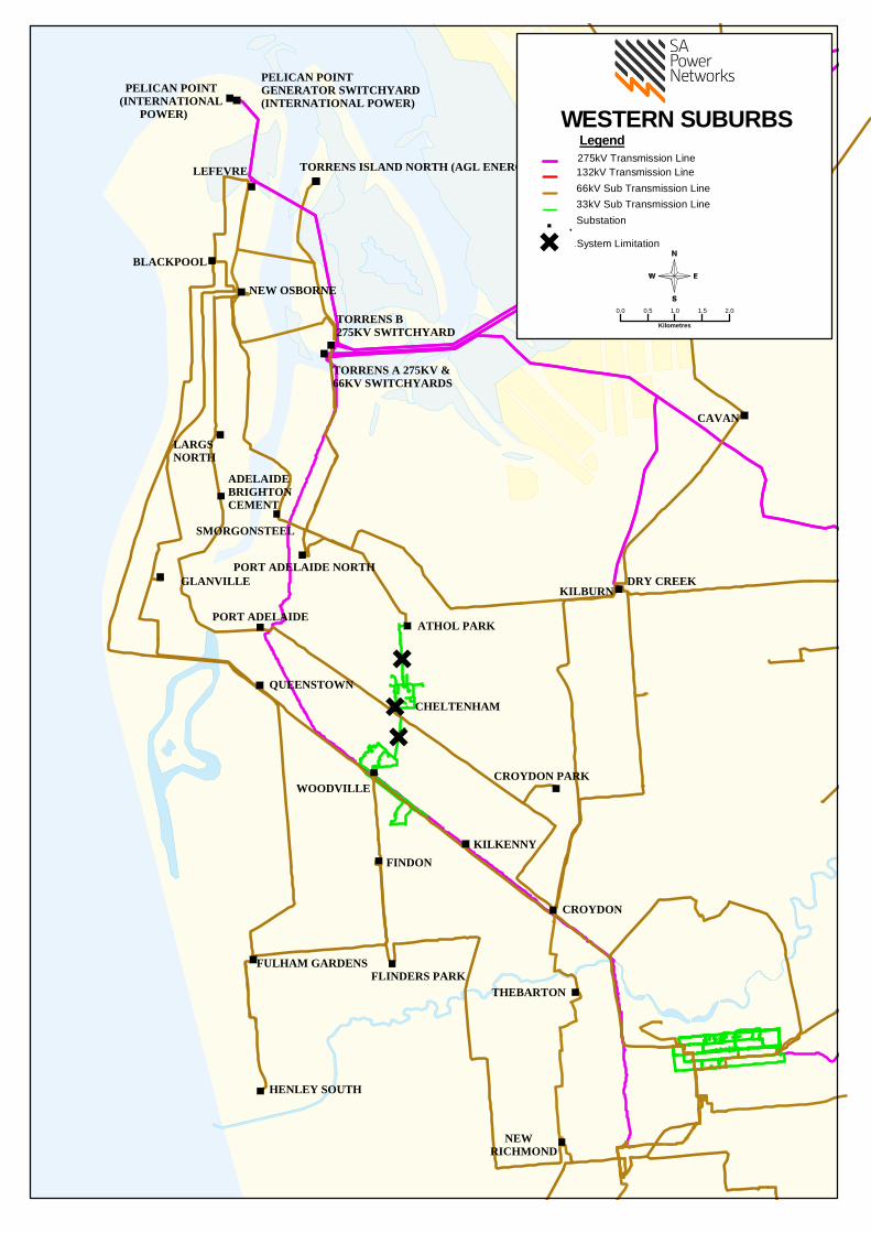
HENLEY SOUTH
PELICAN POINTGENERATOR SWITCHYARD(INTERNATIONAL POWER)
FULHAM GARDENSFLINDERS PARK
WOODVILLE
QUEENSTOWN
FINDON
GLANVILLE
LARGS NORTH
CAVAN
PORT ADELAIDE
SMORGONSTEEL
ADELAIDEBRIGHTON CEMENT
PORT ADELAIDE NORTH
PELICAN POINT(INTERNATIONAL POWER)
LEFEVRE
NEW OSBORNE
TORRENS A 275KV & 66KV SWITCHYARDS
TORRENS B 275KV SWITCHYARD
TORRENS ISLAND NORTH (AGL ENERGY)
THEBARTON
KILKENNY
CHELTENHAM
CROYDON PARK
CROYDON
ATHOL PARK
NEW RICHMOND
KILBURNDRY CREEK
BLACKPOOL
0.0 0.5 1.0 1.5 2.0
Kilometres
Legend275kV Transmission Line132kV Transmission Line66kV Sub Transmission Line33kV Sub Transmission LineSubstation
WESTERN SUBURBS
.System Limitation.

Distribution Annual Planning Report
Version 1.1 Page 59
Substation: Metro West 275/66kV
Region: Metro West
(ETC) Transmission Category: 4
Number of Transformers: 5
Total Nameplate Rating (MVA): 845 MVA
Actuals*
Year 2009/2010 2010/2011 2011/2012 2012/2013 2013/2014
Sum
mer
MW 449 454 407 408 438
MVAr 31 19 24 50 53
MVA 450 454 407 411 441
PF 1.00 1.00 1.00 0.99 0.99
Year 2009 2010 2011 2012 2013
Win
ter MW 308 327 308 300 319
MVAr 39 45 30 58 37
MVA 311 330 310 306 321
PF 0.99 0.99 1.00 0.98 0.99
Forecast^
Sum
mer
10% POE Forecast 2014/2015 2015/2016 2016/2017 2017/2018 2018/2019
MW 421 418 415 412 405
MVAr 47 47 47 46 45
MVA 423 420 417 415 407
PF 1.0 1.0 1.0 1.0 1.0
Firm Delivery Capacity (MVA) 660 660 660 660 660
System Limitation (Y/N) N N N N N
Hrs per annum > 95% of Peak Load (hrs)
Year Former Step Change (MVA) Year Future Step Change (10% POE MVA)
2013/14 +43.5MW from Northern Suburbs due to Cavan transfer
*Potential impact of below embedded generation has been removed from the above Actuals: (i.e. generation output = 0)
8MW of dump export generation (2009/10 to 2012/13)
4MW of dump export generation (2013/14)
^Impact of below embedded generation included in the Forecast: (i.e. generation output = up to 4MW)
4MW of dump export generation

Distribution Annual Planning Report
Version 1.1 Page 60
Substation: Athol Park 66/11kV
Region: Metro West
Number of Feeders: 4
Number of Transformers: 2
Total Nameplate Rating (MVA): 20 MVA
Actuals
Year 2009/2010 2010/2011 2011/2012 2012/2013 2013/2014
Sum
mer
MW 19.0 22.3 20.2 19.9 18.3
MVAr 4.8 4.7 5.4 4.6 2.8
MVA 19.6 22.8 20.9 20.4 18.5
PF 0.97 0.98 0.97 0.98 0.99
Year 2009 2010 2011 2012 2013
Win
ter MW 18.2 18.2 16.2 15.7 14.7
MVAr 2.3 2.0 6.6 7.5 6.9
MVA 18.3 18.3 17.5 17.4 16.3
PF 0.99 0.99 0.93 0.90 0.91
Forecast
Sum
mer
10% POE Forecast 2014/2015 2015/2016 2016/2017 2017/2018 2018/2019
MW 17.7 17.3 17.0 16.7 16.4
MVAr 4.0 3.9 3.8 3.8 3.7
MVA 18.1 17.8 17.4 17.1 16.8
PF 0.98 0.98 0.98 0.98 0.98
Total Capacity (MVA) 26.5 26.5 26.5 26.5 26.5
50% POE Forecast
MW 16.3 15.9 15.6 15.3 15.0
MVAr 3.7 3.6 3.5 3.4 3.4
MVA 16.7 16.4 16 15.7 15.3
PF 0.98 0.98 0.98 0.98 0.98
Firm Delivery Capacity (MVA) 14.3 14.3 14.3 14.3 14.3
Transfer Capacity (MVA) 12.1
12.4
12.7
12.9
13.2 System Limitation (Y/N) N N N N N
Hrs per annum > 95% of Peak Load (hrs) 7
Year Former Step Change (MVA) Year Future Step Change (10% POE MVA)
2010/11 +0.9MVA from Port Adelaide North

Distribution Annual Planning Report
Version 1.1 Page 61
Substation: Blackpool 66/7.6kV
Region: Metro West
Number of Feeders: 4
Number of Transformers: 2
Total Nameplate Rating (MVA): 16 MVA
Actuals
Year 2009/2010 2010/2011 2011/2012 2012/2013 2013/2014
Sum
mer
MW 14.6 14.9 12.5 12.8 14.7
MVAr 4.9 5.3 4.5 4.4 4.2
MVA 15.4 15.8 13.3 13.5 15.3
PF 0.95 0.94 0.94 0.95 0.96
Year 2009 2010 2011 2012 2013
Win
ter MW 10.9 10.7 10.0 10.1 10.1
MVAr 3.4 2.9 2.5 2.4 2.1
MVA 11.4 11.1 10.3 10.4 10.3
PF 0.95 0.97 0.97 0.97 0.98
Forecast
Sum
mer
10% POE Forecast 2014/2015 2015/2016 2016/2017 2017/2018 2018/2019
MW 13.6 13.5 13.3 13.2 13.0
MVAr 4.4 4.4 4.4 4.3 4.3
MVA 14.3 14.2 14.0 13.9 13.7
PF 0.95 0.95 0.95 0.95 0.95
Total Capacity (MVA) 19.9 19.9 19.9 19.9 19.9
50% POE Forecast
MW 12.2 12.0 11.9 11.8 11.6
MVAr 4.0 3.9 3.9 3.8 3.8
MVA 12.8
12.7
12.5
12.4
12.3 PF 0.95 0.95 0.95 0.95 0.95
Firm Delivery Capacity (MVA) 10.5 10.5 10.5 10.5 10.5
Transfer Capacity (MVA) 5.6
5.7
5.8
5.9
5.9 System Limitation (Y/N) N N N N N
Hrs per annum > 95% of Peak Load (hrs) 7
Year Former Step Change (MVA) Year Future Step Change (10% POE MVA)

Distribution Annual Planning Report
Version 1.1 Page 62
Substation: Cavan 66/11kV
Region: Metro West
Number of Feeders: 8
Number of Transformers: 2
Total Nameplate Rating (MVA): 50 MVA
Actuals
Year 2009/2010 2010/2011 2011/2012 2012/2013 2013/2014
Sum
mer
MW 37.4 43.9 40.4 42.2 43.2
MVAr 16.0 17.3 16.3 17.4 17.5
MVA 40.7 47.2 43.5 45.7 46.6
PF 0.92 0.93 0.93 0.93 0.93
Year 2009 2010 2011 2012 2013
Win
ter MW 22.6 26.7 26.5 30.1 25.9
MVAr 8.7 10.1 9.2 9.1 8.0
MVA 24.2 28.6 28.1 31.4 27.1
PF 0.93 0.94 0.94 0.96 0.96
Forecast
Sum
mer
10% POE Forecast 2014/2015 2015/2016 2016/2017 2017/2018 2018/2019
MW 38.7 39.5 40.3 41.4 37.0
MVAr 15.6 15.9 16.2 16.6 14.9
MVA 41.8 42.6 43.4 44.6 39.9
PF 0.93 0.93 0.93 0.93 0.93
Total Capacity (MVA) 58.2 58.2 58.2 58.2 58.2
50% POE Forecast
MW 35.3 36.0 36.7 37.7 33.2
MVAr 14.2 14.5 14.8 15.2 13.4
MVA 38.0
38.8
39.5
40.6
35.8 PF 0.93 0.93 0.93 0.93 0.93
Firm Delivery Capacity (MVA) 31.6 31.6 31.6 31.6 31.6
Transfer Capacity (MVA) 17.9
17.5
17.0
16.6
16.2 System Limitation (Y/N) N N N N N
Hrs per annum > 95% of Peak Load (hrs) 7
Year Former Step Change (MVA) Year Future Step Change (10% POE MVA)
2010/11 -2.3MVA to Northfield 2014/15 -4.6MVA to Parafield Gardens
+5.0MVA from Kilburn

Distribution Annual Planning Report
Version 1.1 Page 63
Substation: Cheltenham 66/7.6kV
Region: Metro West
Number of Feeders: 2
Number of Transformers: 1
Total Nameplate Rating (MVA): 5 MVA
Actuals
Year 2009/2010 2010/2011 2011/2012 2012/2013 2013/2014
Sum
mer
MW 3.9 4.6 3.6 3.6 4.1
MVAr 1.8 2.2 1.2 1.5 1.3
MVA 4.3 5.1 3.8 3.9 4.3
PF 0.91 0.90 0.95 0.93 0.95
Year 2009 2010 2011 2012 2013
Win
ter MW 3.0 2.2 3.1 2.8 2.8
MVAr 1.0 1.1 0.8 0.8 0.7
MVA 3.1 2.5 3.2 2.9 2.9
PF 0.95 0.90 0.97 0.97 0.97
Forecast
Sum
mer
10% POE Forecast 2014/2015 2015/2016 2016/2017 2017/2018 2018/2019
MW 3.8 3.7 3.7 3.7 3.6
MVAr 1.4 1.4 1.4 1.3 1.3
MVA 4.0 4.0 3.9 3.9 3.9
PF 0.94 0.94 0.94 0.94 0.94
Total Capacity (MVA) 4.8 4.8 4.8 4.8 4.8
50% POE Forecast
MW 3.3 3.3 3.3 3.3 3.2
MVAr 1.2 1.2 1.2 1.2 1.2
MVA 3.5
3.5
3.5
3.5
3.4 PF 0.94 0.94 0.94 0.94 0.94
Firm Delivery Capacity (MVA) 0.0 0.0 0.0 0.0 0.0
Transfer Capacity (MVA) 0.9
0.9
0.9
0.9
1.0 System Limitation (Y/N) Y Y Y Y Y
Hrs per annum > 95% of Peak Load (hrs) 5
Year Former Step Change (MVA) Year Future Step Change (10% POE MVA)
2010/11 -1.2MVA to Cheltenham 11kV 2016/17 -3.9MVA to Cheltenham 11kV
+0.6MVA from Woodville 7.6kV
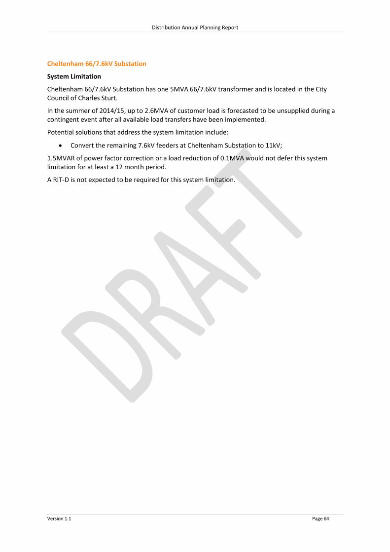
Distribution Annual Planning Report
Version 1.1 Page 64
Cheltenham 66/7.6kV Substation
System Limitation
Cheltenham 66/7.6kV Substation has one 5MVA 66/7.6kV transformer and is located in the City Council of Charles Sturt.
In the summer of 2014/15, up to 2.6MVA of customer load is forecasted to be unsupplied during a contingent event after all available load transfers have been implemented.
Potential solutions that address the system limitation include:
Convert the remaining 7.6kV feeders at Cheltenham Substation to 11kV;
1.5MVAR of power factor correction or a load reduction of 0.1MVA would not defer this system limitation for at least a 12 month period.
A RIT-D is not expected to be required for this system limitation.

Distribution Annual Planning Report
Version 1.1 Page 65
Substation: Cheltenham 66/33kV
Region: Metro West
Number of Feeders: 2
Number of Transformers: 1
Total Nameplate Rating (MVA): 20 MVA
Actuals
Year 2009/2010 2010/2011 2011/2012 2012/2013 2013/2014
Sum
mer
MW 6.0 5.6 3.8 3.9 3.4
MVAr 4.2 4.2 2.4 3.0 1.9
MVA 7.3 7.0 4.5 4.9 3.9
PF 0.82 0.80 0.84 0.79 0.87
Year 2009 2010 2011 2012 2013
Win
ter MW 5.8 5.1 4.4 4.0 3.8
MVAr 4.3 4.6 3.3 3.2 3.2
MVA 7.2 6.8 5.5 5.1 5.0
PF 0.80 0.74 0.80 0.78 0.76
Forecast
Sum
mer
10% POE Forecast 2014/2015 2015/2016 2016/2017 2017/2018 2018/2019
MW 3.3 3.3 3.3 3.2 3.2
MVAr 2.2 2.2 2.2 2.1 2.1
MVA 4.0 4.0 3.9 3.9 3.8
PF 0.83 0.83 0.83 0.83 0.83
Total Capacity (MVA) 19.0 19.0 19.0 19.0 19.0
50% POE Forecast
MW 3.3 3.3 3.3 3.3 3.2
MVAr 2.2 2.2 2.2 2.2 2.1
MVA 4.0
4.0
3.9
3.9
3.9 PF 0.83 0.83 0.83 0.83 0.83
Firm Delivery Capacity (MVA) 0.0 0.0 0.0 0.0 0.0
Transfer Capacity (MVA) 7.3
7.3
7.3
7.3
7.3 System Limitation (Y/N) N N N N N
Hrs per annum > 95% of Peak Load (hrs) 5
Year Former Step Change (MVA) Year Future Step Change (10% POE MVA)
2010/11 -1.0MVA Customer load decrease 2016/17 +3.9MVA from Cheltenham 7.6kV
2011/12 -0.8MVA Customer load decrease

Distribution Annual Planning Report
Version 1.1 Page 66
Substation: Cheltenham 66/11kV
Region: Metro West
Number of Feeders: 3
Number of Transformers: 1
Total Nameplate Rating (MVA): 25 MVA
Actuals
Year 2009/2010 2010/2011 2011/2012 2012/2013 2013/2014
Sum
mer
MW N/A N/A 3.4 3.8 5.0
MVAr N/A N/A 0.8 1.0 1.1
MVA N/A N/A 3.5 3.9 5.1
PF N/A N/A 0.97 0.97 0.97
Year 2009 2010 2011 2012 2013
Win
ter MW N/A N/A 2.4 2.7 3.0
MVAr N/A N/A 0.7 0.4 0.4
MVA N/A N/A 2.5 2.7 3.1
PF N/A N/A 0.96 0.99 0.99
Forecast
Sum
mer
10% POE Forecast 2014/2015 2015/2016 2016/2017 2017/2018 2018/2019
MW 4.6 4.7 4.8 4.9 5.0
MVAr 1.1 1.1 1.2 1.2 1.2
MVA 4.7 4.8 4.9 5.0 5.1
PF 0.97 0.97 0.97 0.97 0.97
Total Capacity (MVA) 29.9 29.9 29.9 29.9 29.9
50% POE Forecast
MW 4.0 4.1 4.2 4.3 4.4
MVAr 1.0 1.0 1.0 1.0 1.1
MVA 4.2
4.2
4.3
4.4
4.5 PF 0.97 0.97 0.97 0.97 0.97
Firm Delivery Capacity (MVA) 0.0 0.0 0.0 0.0 0.0
Transfer Capacity (MVA) 2.4
2.4
2.3+5
2.3
2.2 System Limitation (Y/N) Y* Y* Y* Y* Y*
Hrs per annum > 95% of Peak Load (hrs) 9
Year Former Step Change (MVA) Year Future Step Change (10% POE MVA)
2010/11 +1.2MVA from Cheltenham 7.6kV
+0.6MVA Customer load increase
2011/12 +1.5MVA from Port Adelaide North
+0.4MVA Customer load increase
*Within planning criteria risk margin

Distribution Annual Planning Report
Version 1.1 Page 67
Substation: Croydon 66/11kV
Region: Metro West
Number of Feeders: 9
Number of Transformers: 2
Total Nameplate Rating (MVA): 42 MVA
Actuals
Year 2009/2010 2010/2011 2011/2012 2012/2013 2013/2014
Sum
mer
MW 34.1 37.7 34.1 27.9 29.2
MVAr 11.2 12.1 10.2 6.4 5.9
MVA 35.9 39.6 35.6 28.6 29.8
PF 0.95 0.95 0.96 0.98 0.98
Year 2009 2010 2011 2012 2013
Win
ter MW 26.7 24.9 25.0 24.0 20.3
MVAr 5.3 11.5 3.2 2.8 1.2
MVA 27.2 27.4 25.2 24.2 20.3
PF 0.98 0.91 0.99 0.99 1.00
Forecast
Sum
mer
10% POE Forecast 2014/2015 2015/2016 2016/2017 2017/2018 2018/2019
MW 27.5 27.0 26.4 25.9 25.4
MVAr 6.6 6.5 6.4 6.3 6.1
MVA 28.3 27.7 27.2 26.6 26.1
PF 0.97 0.97 0.97 0.97 0.97
Total Capacity (MVA) 48.4 48.4 48.4 48.4 48.4
50% POE Forecast
MW 25.3 24.8 24.2 23.7 23.2
MVAr 6.1 6.0 5.8 5.7 5.6
MVA 26 25.5 24.9 24.4 23.9
PF 0.97 0.97 0.97 0.97 0.97
Firm Delivery Capacity (MVA) 25.6 25.6 25.6 25.6 25.6
Transfer Capacity (MVA) 26.3
26.9
27.6
28.2
28.9 System Limitation (Y/N) N N N N N
Hrs per annum > 95% of Peak Load (hrs) 9
Year Former Step Change (MVA) Year Future Step Change (10% POE MVA)
2009/10 -0.8MVA to Thebarton
-0.3MVA to Kilkenny
2012/13 -4.7MVA Customer load decrease

Distribution Annual Planning Report
Version 1.1 Page 68
Substation: Croydon Park 66/11kV
Region: Metro West
Number of Feeders: 5
Number of Transformers: 2
Total Nameplate Rating (MVA): 20 MVA
Actuals
Year 2009/2010 2010/2011 2011/2012 2012/2013 2013/2014
Sum
mer
MW 22.6 21.5 17.8 18.5 19.1
MVAr 9.7 8.4 7.5 8.2 7.7
MVA 24.6 23.1 19.3 20.3 20.6
PF 0.92 0.93 0.92 0.92 0.93
Year 2009 2010 2011 2012 2013
Win
ter MW 17.4 14.3 11.4 12.4 13.2
MVAr 5.3 4.3 2.6 4.0 3.3
MVA 18.2 14.9 11.7 13.1 13.6
PF 0.96 0.96 0.97 0.95 0.97
Forecast
Sum
mer
10% POE Forecast 2014/2015 2015/2016 2016/2017 2017/2018 2018/2019
MW 17.8 17.4 17.0 16.6 16.2
MVAr 7.5 7.3 7.1 6.9 6.8
MVA 19.3 18.9 18.4 18.0 17.5
PF 0.92 0.92 0.92 0.92 0.92
Total Capacity (MVA) 26.4 26.4 26.4 26.4 26.4
50% POE Forecast
MW 16.3 15.9 15.4 15.0 14.6
MVAr 6.8 6.6 6.4 6.3 6.1
MVA 17.6
17.2
16.7
16.3
15.9 PF 0.92 0.92 0.92 0.92 0.92
Firm Delivery Capacity (MVA) 13.7 13.7 13.7 13.7 13.7
Transfer Capacity (MVA) 16.1
16.6
17.1
17.6
18.1 System Limitation (Y/N) N N N N N
Hrs per annum > 95% of Peak Load (hrs) 7
Year Former Step Change (MVA) Year Future Step Change (10% POE MVA)

Distribution Annual Planning Report
Version 1.1 Page 69
Substation: Findon 66/11kV
Region: Metro West
Number of Feeders: 4
Number of Transformers: 2
Total Nameplate Rating (MVA): 20 MVA
Actuals
Year 2009/2010 2010/2011 2011/2012 2012/2013 2013/2014
Sum
mer
MW 17.7 19.5 16.4 16.5 18.6
MVAr 6.9 7.8 5.8 6.5 6.7
MVA 19.0 21.0 17.4 17.7 19.8
PF 0.93 0.93 0.94 0.93 0.94
Year 2009 2010 2011 2012 2013
Win
ter MW 11.2 12.5 11.6 11.7 10.7
MVAr 3.1 3.4 2.7 3.4 2.9
MVA 11.6 13.0 11.9 12.2 11.1
PF 0.96 0.97 0.98 0.96 0.97
Forecast
Sum
mer
10% POE Forecast 2014/2015 2015/2016 2016/2017 2017/2018 2018/2019
MW 19.6 19.4 19.3 19.1 19.0
MVAr 7.1 7.1 7.0 7.0 6.9
MVA 20.8 20.7 20.5 20.4 20.2
PF 0.94 0.94 0.94 0.94 0.94
Total Capacity (MVA) 24.8 24.8 24.8 24.8 24.8
50% POE Forecast
MW 17.8 17.6 17.5 17.3 17.2
MVAr 6.5 6.4 6.4 6.3 6.3
MVA 18.9
18.8
18.6
18.5
18.3 PF 0.94 0.94 0.94 0.94 0.94
Firm Delivery Capacity (MVA) 14.1 14.1 14.1 14.1 14.1
Transfer Capacity (MVA) 11.1
11.2
11.2
11.3
11.4 System Limitation (Y/N) N N N N N
Hrs per annum > 95% of Peak Load (hrs) 6
Year Former Step Change (MVA) Year Future Step Change (10% POE MVA)

Distribution Annual Planning Report
Version 1.1 Page 70
Substation: Flinders Park 66/11kV
Region: Metro West
Number of Feeders: 4
Number of Transformers: 2
Total Nameplate Rating (MVA): 20 MVA
Actuals
Year 2009/2010 2010/2011 2011/2012 2012/2013 2013/2014
Sum
mer
MW 20.5 21.2 18.0 18.9 19.3
MVAr 8.0 8.4 7.7 8.0 9.0
MVA 22.0 22.8 19.6 20.5 21.3
PF 0.93 0.93 0.92 0.92 0.91
Year 2009 2010 2011 2012 2013
Win
ter MW 14.5 14.5 13.0 12.1 11.7
MVAr 4.2 5.8 4.3 6.0 5.3
MVA 15.1 15.6 13.7 13.5 12.8
PF 0.96 0.93 0.95 0.90 0.91
Forecast
Sum
mer
10% POE Forecast 2014/2015 2015/2016 2016/2017 2017/2018 2018/2019
MW 20.8 21.0 21.1 21.2 21.3
MVAr 9.3 9.3 9.4 9.4 9.5
MVA 22.8 23.0 23.1 23.2 23.3
PF 0.91 0.91 0.91 0.91 0.91
Total Capacity (MVA) 27.3 27.3 27.3 27.3 27.3
50% POE Forecast
MW 18.9 19.0 19.2 19.3 19.4
MVAr 8.4 8.5 8.5 8.6 8.6
MVA 20.7
20.8
21.0
21.1
21.2 PF 0.91 0.91 0.91 0.91 0.91
Firm Delivery Capacity (MVA) 14.1 14.1 14.1 14.1 14.1
Transfer Capacity (MVA) 20.4
20.3
20.2
20.1
20.0 System Limitation (Y/N) N N N N N
Hrs per annum > 95% of Peak Load (hrs) 6
Year Former Step Change (MVA) Year Future Step Change (10% POE MVA)
2009/10 -1.7MVA to Fulham Gardens

Distribution Annual Planning Report
Version 1.1 Page 71
Substation: Fulham Gardens 66/11kV
Region: Metro West
Number of Feeders: 6
Number of Transformers: 2
Total Nameplate Rating (MVA): 42 MVA
Actuals
Year 2009/2010 2010/2011 2011/2012 2012/2013 2013/2014
Sum
mer
MW 37.0 38.5 33.5 34.2 40.4
MVAr 14.4 14.9 12.9 13.1 14.4
MVA 39.7 41.3 35.9 36.7 42.9
PF 0.93 0.93 0.93 0.93 0.94
Year 2009 2010 2011 2012 2013
Win
ter MW 25.1 27.1 24.6 26.7 25.1
MVAr 7.8 7.8 6.3 7.4 7.2
MVA 26.3 28.2 25.4 27.7 26.1
PF 0.96 0.96 0.97 0.96 0.96
Forecast
Sum
mer
10% POE Forecast 2014/2015 2015/2016 2016/2017 2017/2018 2018/2019
MW 37.0 37.1 37.2 37.3 37.4
MVAr 13.9 13.9 14.0 14.0 14.0
MVA 39.5 39.6 39.7 39.9 39.9
PF 0.94 0.94 0.94 0.94 0.94
Total Capacity (MVA) 49.0 49.0 49.0 49.0 49.0
50% POE Forecast
MW 32.6 32.6 32.7 32.7 32.8
MVAr 12.2 12.2 12.3 12.3 12.3
MVA 34.8
34.8
34.9
35.0
35.0 PF 0.94 0.94 0.94 0.94 0.94
Firm Delivery Capacity (MVA) 24.8 24.8 24.8 24.8 24.8
Transfer Capacity (MVA) 12.9
13.0
13.0
13.0
13.0 System Limitation (Y/N) N N N N N
Hrs per annum > 95% of Peak Load (hrs) 7
Year Former Step Change (MVA) Year Future Step Change (10% POE MVA)
2009/10 +1.7MVA from Flinders Park
2010/11 +1.0MVA from Henley South
2013/14 +2.1MVA Customer load increase

Distribution Annual Planning Report
Version 1.1 Page 72
Substation: Glanville 66/7.6kV
Region: Metro West
Number of Feeders: 5
Number of Transformers: 2
Total Nameplate Rating (MVA): 16 MVA
Actuals
Year 2009/2010 2010/2011 2011/2012 2012/2013 2013/2014
Sum
mer
MW 14.2 14.2 11.5 11.6 13.5
MVAr 5.7 5.1 3.1 3.1 4.2
MVA 15.3 15.1 11.9 12.0 14.2
PF 0.93 0.94 0.97 0.97 0.95
Year 2009 2010 2011 2012 2013
Win
ter MW 10.4 10.5 9.9 9.2 8.8
MVAr 3.4 3.3 2.8 2.5 1.7
MVA 11.0 11.0 10.3 9.5 9.0
PF 0.95 0.96 0.96 0.97 0.98
Forecast
Sum
mer
10% POE Forecast 2014/2015 2015/2016 2016/2017 2017/2018 2018/2019
MW 12.3 12.3 12.2 12.2 12.2
MVAr 3.5 3.5 3.5 3.5 3.5
MVA 12.8 12.8 12.7 12.7 12.6
PF 0.96 0.96 0.96 0.96 0.96
Total Capacity (MVA) 20.4 20.4 20.4 20.4 20.4
50% POE Forecast
MW 10.9 10.8 10.8 10.7 10.6
MVAr 3.1 3.1 3.1 3.1 3.0
MVA 11.3
11.3
11.2
11.1
11.1 PF 0.96 0.96 0.96 0.96 0.96
Firm Delivery Capacity (MVA) 12.0 12.0 12.0 12.0 12.0
Transfer Capacity (MVA) 7.9
8.0
8.1
8.2
8.3 System Limitation (Y/N) N N N N N
Hrs per annum > 95% of Peak Load (hrs) 6
Year Former Step Change (MVA) Year Future Step Change (10% POE MVA)
2009/10 +0.4MVA Customer load increase
2010/11 +0.4MVA Customer load increase
2011/12 -0.4MVA Customer load decrease
-0.8MVA to Largs North

Distribution Annual Planning Report
Version 1.1 Page 73
Substation: Henley South 66/11kV
Region: Metro West
Number of Feeders: 8
Number of Transformers: 2
Total Nameplate Rating (MVA): 48 MVA
Actuals
Year 2009/2010 2010/2011 2011/2012 2012/2013 2013/2014
Sum
mer
MW 31.1 34.4 29.5 29.3 33.8
MVAr 10.4 12.2 10.2 10.2 11.0
MVA 32.8 36.5 31.2 31.0 35.5
PF 0.95 0.94 0.95 0.94 0.95
Year 2009 2010 2011 2012 2013
Win
ter MW 21.7 24.0 22.5 23.5 21.0
MVAr 5.0 6.2 5.7 5.5 5.2
MVA 22.2 24.8 23.2 24.1 21.6
PF 0.97 0.97 0.97 0.97 0.97
Forecast
Sum
mer
10% POE Forecast 2014/2015 2015/2016 2016/2017 2017/2018 2018/2019
MW 30.6 30.6 30.7 30.7 30.7
MVAr 10.4 10.4 10.5 10.5 10.5
MVA 32.3 32.3 32.4 32.4 32.5
PF 0.95 0.95 0.95 0.95 0.95
Total Capacity (MVA) 55.7 55.7 55.7 55.7 55.7
50% POE Forecast
MW 27.1 27.2 27.3 27.4 27.4
MVAr 9.3 9.3 9.3 9.3 9.4
MVA 28.7
28.8
28.8
28.9
29.0 PF 0.95 0.95 0.95 0.95 0.95
Firm Delivery Capacity (MVA) 30.5 30.5 30.5 30.5 30.5
Transfer Capacity (MVA) 12.0
12.0
12.0
12.0
12.1 System Limitation (Y/N) N N N N N
Hrs per annum > 95% of Peak Load (hrs) 7
Year Former Step Change (MVA) Year Future Step Change (10% POE MVA)
2010/11 -1.0MVA to Fulham Gardens

Distribution Annual Planning Report
Version 1.1 Page 74
Substation: Kilburn 66/11kV
Region: Metro West
Number of Feeders: 8
Number of Transformers: 3
Total Nameplate Rating (MVA): 63 MVA
Actuals*
Year 2009/2010 2010/2011 2011/2012 2012/2013 2013/2014
Sum
mer
MW 49.4 44.6 44.7 44.1 39.3
MVAr 28.6 27.5 26.0 25.5 22.7
MVA 57.1 52.4 51.7 50.9 45.4
PF 0.87 0.85 0.87 0.87 0.87
Year 2009 2010 2011 2012 2013
Win
ter MW 42.8 45.2 43.6 40.2 39.8
MVAr 26.1 28.2 24.3 20.9 20.9
MVA 50.1 53.3 49.9 45.3 44.9
PF 0.85 0.85 0.87 0.89 0.89
Forecast^
Sum
mer
10% POE Forecast 2014/2015 2015/2016 2016/2017 2017/2018 2018/2019
MW 39.4 38.7 38.1 37.4 36.7
MVAr 24.0 23.6 23.2 22.8 22.4
MVA 46.2 45.3 44.6 43.8 43.0
PF 0.85 0.85 0.85 0.85 0.85
Total Capacity (MVA) 76.2 76.2 76.2 76.2 76.2
50% POE Forecast
MW 37.8 37.3 36.7 36.2 35.6
MVAr 23.1 22.7 22.4 22.1 21.7
MVA 44.3
43.7
43.0
42.4
41.7 PF 0.85 0.85 0.85 0.85 0.85
Firm Delivery Capacity (MVA) 54.3 54.3 54.3 54.3 54.3
Transfer Capacity (MVA) 11.1
11.3
11.5
11.8
12.0 System Limitation (Y/N) N N N N N
Hrs per annum > 95% of Peak Load (hrs) 3
Year Former Step Change (MVA) Year Future Step Change (10% POE MVA)
2010/11 -5.0MVA to Cavan
*Potential impact of below embedded generation has been removed from the above Actuals: (i.e. generation output = 0)
4MW of dump export generation (2009/10 to 2012/13)
2MW of dump export generation (2013/14)
^Impact of below embedded generation included in the Forecast: (i.e. generation output = up to 2MW)
2MW of dump export generation

Distribution Annual Planning Report
Version 1.1 Page 75
Substation: Kilkenny 66/11kV
Region: Metro West
Number of Feeders: 4
Number of Transformers: 2
Total Nameplate Rating (MVA): 50 MVA
Actuals
Year 2009/2010 2010/2011 2011/2012 2012/2013 2013/2014
Sum
mer
MW 15.2 15.1 14.9 14.4 15.1
MVAr 5.9 5.9 4.6 5.2 3.9
MVA 16.3 16.2 15.6 15.3 15.6
PF 0.93 0.93 0.96 0.94 0.97
Year 2009 2010 2011 2012 2013
Win
ter MW 14.3 19.7 13.5 12.6 12.4
MVAr 5.7 5.6 5.0 3.2 3.8
MVA 15.4 20.5 14.4 13.0 12.9
PF 0.93 0.96 0.94 0.97 0.96
Forecast
Sum
mer
10% POE Forecast 2014/2015 2015/2016 2016/2017 2017/2018 2018/2019
MW 14.0 13.5 13.0 12.6 12.2
MVAr 4.4 4.2 4.1 3.9 3.8
MVA 14.6 14.2 13.7 13.2 12.7
PF 0.95 0.95 0.95 0.95 0.95
Total Capacity (MVA) 55.9 55.9 55.9 55.9 55.9
50% POE Forecast
MW 12.9 12.3 11.7 11.1 10.6
MVAr 4.0 3.8 3.6 3.5 3.3
MVA 13.5
12.9
12.3
11.7
11.1 PF 0.95 0.95 0.95 0.95 0.95
Firm Delivery Capacity (MVA) 31.4 31.4 31.4 31.4 31.4
Transfer Capacity (MVA) 13.5
14.2
14.9
15.6
16.4 System Limitation (Y/N) N N N N N
Hrs per annum > 95% of Peak Load (hrs) 9
Year Former Step Change (MVA) Year Future Step Change (10% POE MVA)
2009/10 +0.3MVA from Croydon

Distribution Annual Planning Report
Version 1.1 Page 76
Substation: Largs North 66/7.6kV
Region: Metro West
Number of Feeders: 5
Number of Transformers: 2
Total Nameplate Rating (MVA): 20 MVA
Actuals
Year 2009/2010 2010/2011 2011/2012 2012/2013 2013/2014
Sum
mer
MW 13.2 14.0 12.0 12.8 14.4
MVAr 5.2 5.4 4.7 4.6 4.8
MVA 14.2 15.0 12.9 13.6 15.2
PF 0.93 0.93 0.93 0.94 0.95
Year 2009 2010 2011 2012 2013
Win
ter MW 10.2 10.6 10.2 10.7 11.0
MVAr 3.7 3.3 3.2 3.0 3.1
MVA 10.9 11.1 10.7 11.1 11.4
PF 0.94 0.96 0.95 0.96 0.96
Forecast
Sum
mer
10% POE Forecast 2014/2015 2015/2016 2016/2017 2017/2018 2018/2019
MW 13.4 13.4 13.3 13.3 13.3
MVAr 4.8 4.8 4.8 4.7 4.7
MVA 14.2 14.2 14.2 14.1 14.1
PF 0.94 0.94 0.94 0.94 0.94
Total Capacity (MVA) 27.5 27.5 27.5 27.5 27.5
50% POE Forecast
MW 11.9 11.9 11.8 11.7 11.7
MVAr 4.2 4.2 4.2 4.2 4.2
MVA 12.7
12.6
12.5
12.5
12.4 PF 0.94 0.94 0.94 0.94 0.94
Firm Delivery Capacity (MVA) 15.0 15.0 15.0 15.0 15.0
Transfer Capacity (MVA) 3.7
3.7
3.7
3.8
3.8 System Limitation (Y/N) N N N N N
Hrs per annum > 95% of Peak Load (hrs) 9
Year Former Step Change (MVA) Year Future Step Change (10% POE MVA)
2010/11 +0.9MVA Customer load Increase
2011/12 +0.8MVA from Glanville
2012/13 +0.6MVA Customer load increase

Distribution Annual Planning Report
Version 1.1 Page 77
Substation: LeFevre 66/11kV
Region: Metro West
Number of Feeders: 6
Number of Transformers: 2
Total Nameplate Rating (MVA): 64 MVA
Actuals
Year 2009/2010 2010/2011 2011/2012 2012/2013 2013/2014
Sum
mer
MW 5.9 7.5 8.8 8.5 9.5
MVAr 4.0 3.6 1.3 2.8 2.1
MVA 7.1 8.3 8.9 8.9 9.7
PF 0.83 0.90 0.99 0.95 0.98
Year 2009 2010 2011 2012 2013
Win
ter MW 4.7 6.4 7.9 7.9 7.7
MVAr 2.3 1.9 1.3 2.4 1.2
MVA 5.2 6.7 8.0 8.3 7.8
PF 0.90 0.96 0.99 0.96 0.99
Forecast
Sum
mer
10% POE Forecast 2014/2015 2015/2016 2016/2017 2017/2018 2018/2019
MW 9.2 9.1 9.0 9.0 8.9
MVAr 2.3 2.3 2.2 2.2 2.2
MVA 9.5 9.4 9.3 9.2 9.1
PF 0.97 0.97 0.97 0.97 0.97
Total Capacity (MVA) 72.2 72.2 72.2 72.2 72.2
50% POE Forecast
MW 9.2 9.2 9.1 9.0 8.9
MVAr 2.3 2.3 2.3 2.2 2.2
MVA 9.5
9.4
9.4
9.3
9.2 PF 0.97 0.97 0.97 0.97 0.97
Firm Delivery Capacity (MVA) 38.1 38.1 38.1 38.1 38.1
Transfer Capacity (MVA) 7.3
7.3
7.4
7.5
7.6 System Limitation (Y/N) N N N N N
Hrs per annum > 95% of Peak Load (hrs) 4
Year Former Step Change (MVA) Year Future Step Change (10% POE MVA)
2010/11 +2.0MVA Customer load increase
2013/14 +2.0MVA Customer load increase
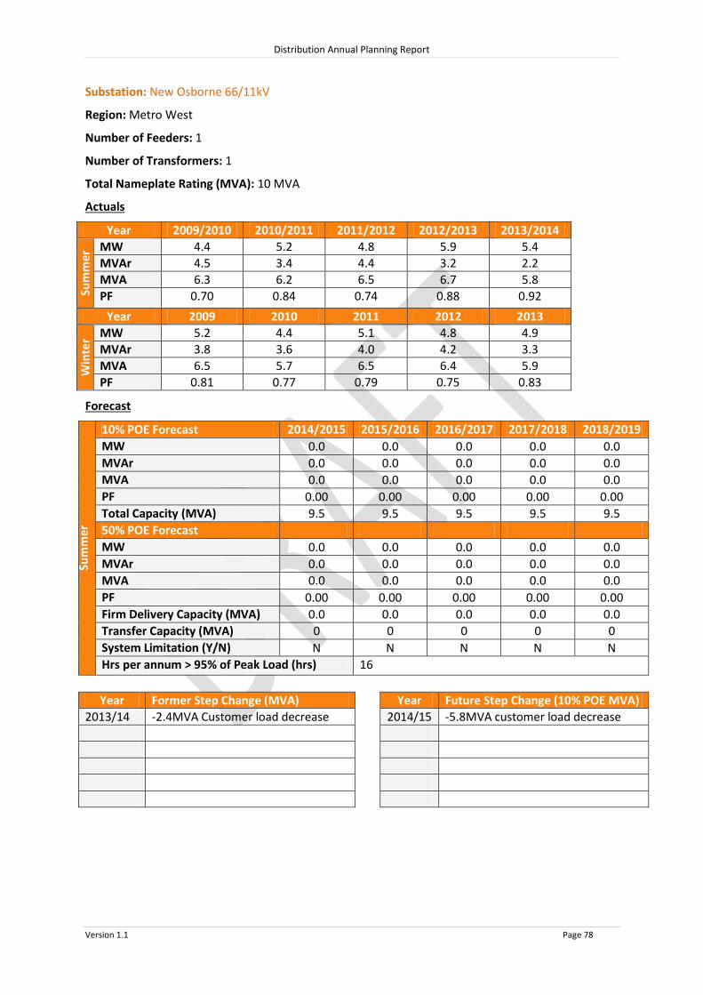
Distribution Annual Planning Report
Version 1.1 Page 78
Substation: New Osborne 66/11kV
Region: Metro West
Number of Feeders: 1
Number of Transformers: 1
Total Nameplate Rating (MVA): 10 MVA
Actuals
Year 2009/2010 2010/2011 2011/2012 2012/2013 2013/2014
Sum
mer
MW 4.4 5.2 4.8 5.9 5.4
MVAr 4.5 3.4 4.4 3.2 2.2
MVA 6.3 6.2 6.5 6.7 5.8
PF 0.70 0.84 0.74 0.88 0.92
Year 2009 2010 2011 2012 2013
Win
ter MW 5.2 4.4 5.1 4.8 4.9
MVAr 3.8 3.6 4.0 4.2 3.3
MVA 6.5 5.7 6.5 6.4 5.9
PF 0.81 0.77 0.79 0.75 0.83
Forecast
Sum
mer
10% POE Forecast 2014/2015 2015/2016 2016/2017 2017/2018 2018/2019
MW 0.0 0.0 0.0 0.0 0.0
MVAr 0.0 0.0 0.0 0.0 0.0
MVA 0.0 0.0 0.0 0.0 0.0
PF 0.00 0.00 0.00 0.00 0.00
Total Capacity (MVA) 9.5 9.5 9.5 9.5 9.5
50% POE Forecast
MW 0.0 0.0 0.0 0.0 0.0
MVAr 0.0 0.0 0.0 0.0 0.0
MVA 0.0
0.0
0.0
0.0
0.0 PF 0.00 0.00 0.00 0.00 0.00
Firm Delivery Capacity (MVA) 0.0 0.0 0.0 0.0 0.0
Transfer Capacity (MVA) 0
0
0
0
0 System Limitation (Y/N) N N N N N
Hrs per annum > 95% of Peak Load (hrs) 16
Year Former Step Change (MVA) Year Future Step Change (10% POE MVA)
2013/14 -2.4MVA Customer load decrease 2014/15 -5.8MVA customer load decrease

Distribution Annual Planning Report
Version 1.1 Page 79
Substation: New Richmond 66/11kV
Region: Metro West
Number of Feeders: 8
Number of Transformers: 2
Total Nameplate Rating (MVA): 42 MVA
Actuals
Year 2009/2010 2010/2011 2011/2012 2012/2013 2013/2014
Sum
mer
MW 37.0 35.7 30.9 31.9 32.4
MVAr 17.9 16.9 15.3 13.1 12.5
MVA 41.1 39.5 34.5 34.5 34.8
PF 0.90 0.90 0.90 0.93 0.93
Year 2009 2010 2011 2012 2013
Win
ter MW 22.3 22.6 22.0 21.5 21.5
MVAr 8.9 8.6 8.8 7.7 7.6
MVA 24.0 24.2 23.7 22.8 22.8
PF 0.93 0.93 0.93 0.94 0.94
Forecast
Sum
mer
10% POE Forecast 2014/2015 2015/2016 2016/2017 2017/2018 2018/2019
MW 30.4 30.3 30.2 30.2 30.1
MVAr 13.2 13.2 13.1 13.1 13.0
MVA 33.1 33.1 33.0 32.9 32.8
PF 0.92 0.92 0.92 0.92 0.92
Total Capacity (MVA) 51.1 51.1 51.1 51.1 51.1
50% POE Forecast
MW 27.6 27.6 27.5 27.5 27.5
MVAr 12.0 12.0 12.0 11.9 11.9
MVA 30.1
30.1
30.0
30.0
30.0 PF 0.92 0.92 0.92 0.92 0.92
Firm Delivery Capacity (MVA) 26.4 26.4 26.4 26.4 26.4
Transfer Capacity (MVA) 16.6
16.6
16.7
16.7
16.7 System Limitation (Y/N) N N N N N
Hrs per annum > 95% of Peak Load (hrs) 7
Year Former Step Change (MVA) Year Future Step Change (10% POE MVA)
2010/11 -0.5MVA to Keswick
-0.5MVA to Thebarton

Distribution Annual Planning Report
Version 1.1 Page 80
Substation: Port Adelaide 66/7.6kV
Region: Metro West
Number of Feeders: 6
Number of Transformers: 2
Total Nameplate Rating (MVA): 16 MVA
Actuals
Year 2009/2010 2010/2011 2011/2012 2012/2013 2013/2014
Sum
mer
MW 12.5 13.0 12.5 12.2 11.8
MVAr 6.7 6.9 5.6 5.9 6.0
MVA 14.2 14.7 13.7 13.6 13.2
PF 0.88 0.88 0.91 0.90 0.89
Year 2009 2010 2011 2012 2013
Win
ter MW 8.9 9.6 8.4 8.4 8.4
MVAr 4.1 4.7 3.5 4.2 3.2
MVA 9.8 10.7 9.1 9.4 9.0
PF 0.91 0.90 0.92 0.89 0.93
Forecast
Sum
mer
10% POE Forecast 2014/2015 2015/2016 2016/2017 2017/2018 2018/2019
MW 10.9 10.8 10.7 10.5 10.4
MVAr 6.0 5.9 5.8 5.7 5.6
MVA 12.5 12.3 12.1 12.0 11.8
PF 0.88 0.88 0.88 0.88 0.88
Total Capacity (MVA) 19.9 19.9 19.9 19.9 19.9
50% POE Forecast
MW 9.9 9.8 9.6 9.5 9.4
MVAr 5.4 5.3 5.2 5.2 5.1
MVA 11.3
11.2
11.0
10.8
10.7 PF 0.88 0.88 0.88 0.88 0.88
Firm Delivery Capacity (MVA) 10.5 10.5 10.5 10.5 10.5
Transfer Capacity (MVA) 5.9
6.0
6.1
6.2
6.3 System Limitation (Y/N) N N N N N
Hrs per annum > 95% of Peak Load (hrs) 7
Year Former Step Change (MVA) Year Future Step Change (10% POE MVA)
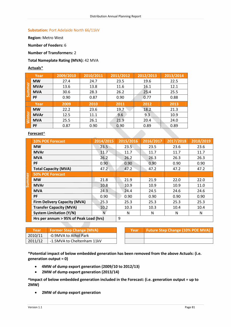
Distribution Annual Planning Report
Version 1.1 Page 81
Substation: Port Adelaide North 66/11kV
Region: Metro West
Number of Feeders: 6
Number of Transformers: 2
Total Nameplate Rating (MVA): 42 MVA
Actuals*
Year 2009/2010 2010/2011 2011/2012 2012/2013 2013/2014
Sum
mer
MW 27.4 24.7 23.5 19.6 22.5
MVAr 13.6 13.8 11.6 16.1 12.1
MVA 30.6 28.3 26.2 25.4 25.5
PF 0.90 0.87 0.90 0.77 0.88
Year 2009 2010 2011 2012 2013
Win
ter MW 22.2 23.6 19.7 18.2 21.3
MVAr 12.5 11.1 9.6 9.3 10.9
MVA 25.5 26.1 21.9 20.4 24.0
PF 0.87 0.90 0.90 0.89 0.89
Forecast^
Sum
mer
10% POE Forecast 2014/2015 2015/2016 2016/2017 2017/2018 2018/2019
MW 23.5 23.5 23.5 23.6 23.6
MVAr 11.7 11.7 11.7 11.7 11.7
MVA 26.2 26.2 26.3 26.3 26.3
PF 0.90 0.90 0.90 0.90 0.90
Total Capacity (MVA) 47.2 47.2 47.2 47.2 47.2
50% POE Forecast
MW 21.8 21.9 21.9 22.0 22.0
MVAr 10.8 10.9 10.9 10.9 11.0
MVA 24.3
24.4
24.5
24.6
24.6 PF 0.90 0.90 0.90 0.90 0.90
Firm Delivery Capacity (MVA) 25.3 25.3 25.3 25.3 25.3
Transfer Capacity (MVA) 10.2
10.3
10.3
10.4
10.4 System Limitation (Y/N) N N N N N
Hrs per annum > 95% of Peak Load (hrs) 9
Year Former Step Change (MVA) Year Future Step Change (10% POE MVA)
2010/11 -0.9MVA to Athol Park
2011/12 -1.5MVA to Cheltenham 11kV
*Potential impact of below embedded generation has been removed from the above Actuals: (i.e. generation output = 0)
4MW of dump export generation (2009/10 to 2012/13)
2MW of dump export generation (2013/14)
^Impact of below embedded generation included in the Forecast: (i.e. generation output = up to 2MW)
2MW of dump export generation

Distribution Annual Planning Report
Version 1.1 Page 82
Substation: Queenstown 66/7.6kV
Region: Metro West
Number of Feeders: 4
Number of Transformers: 2
Total Nameplate Rating (MVA): 16 MVA
Actuals
Year 2009/2010 2010/2011 2011/2012 2012/2013 2013/2014
Sum
mer
MW 15.1 15.4 12.8 13.4 13.8
MVAr 7.4 6.5 5.7 6.4 5.1
MVA 16.8 16.7 14.0 14.8 14.7
PF 0.90 0.92 0.91 0.90 0.94
Year 2009 2010 2011 2012 2013
Win
ter MW 9.9 10.5 9.6 9.5 10.5
MVAr 4.6 3.6 3.7 2.7 2.9
MVA 10.9 11.1 10.3 9.9 10.9
PF 0.91 0.95 0.93 0.96 0.97
Forecast
Sum
mer
10% POE Forecast 2014/2015 2015/2016 2016/2017 2017/2018 2018/2019
MW 12.9 12.7 12.5 12.4 12.2
MVAr 5.4 5.4 5.3 5.2 5.1
MVA 14.0 13.8 13.6 13.4 13.2
PF 0.92 0.92 0.92 0.92 0.92
Total Capacity (MVA) 22.7 22.7 22.7 22.7 22.7
50% POE Forecast
MW 11.5 11.4 11.2 11.1 10.9
MVAr 4.9 4.8 4.7 4.7 4.6
MVA 12.5
12.3
12.2
12.0
11.8 PF 0.92 0.92 0.92 0.92 0.92
Firm Delivery Capacity (MVA) 12.0 12.0 12.0 12.0 12.0
Transfer Capacity (MVA) 6.9
7.0
7.1
7.2
7.3 System Limitation (Y/N) N N N N N
Hrs per annum > 95% of Peak Load (hrs) 9
Year Former Step Change (MVA) Year Future Step Change (10% POE MVA)

Distribution Annual Planning Report
Version 1.1 Page 83
Substation: Thebarton 66/11kV
Region: Metro West
Number of Feeders: 6
Number of Transformers: 2
Total Nameplate Rating (MVA): 42 MVA
Actuals
Year 2009/2010 2010/2011 2011/2012 2012/2013 2013/2014
Sum
mer
MW 32.0 33.9 31.5 31.5 31.8
MVAr 8.5 8.7 7.6 7.6 7.2
MVA 33.1 35.0 32.4 32.4 32.6
PF 0.97 0.97 0.97 0.97 0.98
Year 2009 2010 2011 2012 2013
Win
ter MW 20.6 24.1 22.0 22.1 21.5
MVAr 1.3 2.3 0.0 8.6 1.5
MVA 20.6 24.3 22.0 23.7 21.6
PF 1.00 1.00 1.00 0.93 1.00
Forecast
Sum
mer
10% POE Forecast 2014/2015 2015/2016 2016/2017 2017/2018 2018/2019
MW 30.3 30.1 29.8 29.6 29.4
MVAr 7.1 7.1 7.0 7.0 6.9
MVA 31.1 30.9 30.6 30.4 30.2
PF 0.97 0.97 0.97 0.97 0.97
Total Capacity (MVA) 49.0 49.0 49.0 49.0 49.0
50% POE Forecast
MW 28.2 27.9 27.7 27.4 27.2
MVAr 6.7 6.6 6.5 6.5 6.4
MVA 29.0 28.7 28.4 28.2 27.9
PF 0.97 0.97 0.97 0.97 0.97
Firm Delivery Capacity (MVA) 25.8 25.8 25.8 25.8 25.8
Transfer Capacity (MVA) 13.6
13.7
13.9
14.1
14.3 System Limitation (Y/N) N N N N N
Hrs per annum > 95% of Peak Load (hrs) 7
Year Former Step Change (MVA) Year Future Step Change (10% POE MVA)
2009/10 +0.8MVA from Croydon
2010/11 +1.0MVA Customer load increase
2010/11 +0.5MVA from New Richmond

Distribution Annual Planning Report
Version 1.1 Page 84
Substation: Woodville 66/7.6kV
Region: Metro West
Number of Feeders: 6
Number of Transformers: 2
Total Nameplate Rating (MVA): 10 MVA
Actuals
Year 2009/2010 2010/2011 2011/2012 2012/2013 2013/2014
Sum
mer
MW 6.7 6.2 5.3 5.6 6.8
MVAr 5.9 5.4 4.6 4.9 3.2
MVA 8.9 8.2 7.0 7.4 7.6
PF 0.75 0.76 0.75 0.75 0.91
Year 2009 2010 2011 2012 2013
Win
ter MW 6.2 4.4 3.6 4.1 3.0
MVAr 5.5 3.9 3.2 2.7 2.9
MVA 8.3 5.9 4.8 4.9 4.2
PF 0.75 0.75 0.75 0.83 0.73
Forecast
Sum
mer
10% POE Forecast 2014/2015 2015/2016 2016/2017 2017/2018 2018/2019
MW 6.9 6.9 6.8 6.8 6.7
MVAr 3.8 3.8 3.7 3.7 3.7
MVA 7.9 7.9 7.8 7.7 7.7
PF 0.88 0.88 0.88 0.88 0.88
Total Capacity (MVA) 9.5 9.5 9.5 9.5 9.5
50% POE Forecast
MW 6.0 6.0 5.9 5.9 5.9
MVAr 3.3 3.3 3.2 3.2 3.2
MVA 6.9
6.8
6.8
6.7
6.7 PF 0.88 0.88 0.88 0.88 0.88
Firm Delivery Capacity (MVA) 5.0 5.0 5.0 5.0 5.0
Transfer Capacity (MVA) 3.6
3.6
3.6
3.6
3.7 System Limitation (Y/N) N N N N N
Hrs per annum > 95% of Peak Load (hrs) 9
Year Former Step Change (MVA) Year Future Step Change (10% POE MVA)
2010/11 -0.6MVA to Cheltenham 7.6kV

Distribution Annual Planning Report
Version 1.1 Page 85
Substation: Woodville 66/33kV
Region: Metro West
Number of Feeders: 5
Number of Transformers: 2
Total Nameplate Rating (MVA): 40 MVA
Actuals
Year 2009/2010 2010/2011 2011/2012 2012/2013 2013/2014
Sum
mer
MW 6.7 7.2 7.1 7.0 7.4
MVAr 4.3 4.1 4.7 4.4 3.8
MVA 8.0 8.3 8.5 8.3 8.3
PF 0.84 0.87 0.84 0.85 0.89
Year 2009 2010 2011 2012 2013
Win
ter MW 4.7 5.8 5.6 5.2 5.2
MVAr 3.3 2.8 2.9 2.6 2.2
MVA 5.8 6.4 6.3 5.8 5.7
PF 0.82 0.90 0.89 0.90 0.92
Forecast
Sum
mer
10% POE Forecast 2014/2015 2015/2016 2016/2017 2017/2018 2018/2019
MW 7.2 7.1 7.1 7.0 6.9
MVAr 4.1 4.1 4.0 4.0 4.0
MVA 8.3 8.2 8.1 8.1 8.0
PF 0.87 0.87 0.87 0.87 0.87
Total Capacity (MVA) 37.9 37.9 37.9 37.9 37.9
50% POE Forecast
MW 6.9 6.8 6.8 6.7 6.7
MVAr 3.9 3.9 3.9 3.9 3.8
MVA 7.9
7.9
7.8
7.8
7.7 PF 0.87 0.87 0.87 0.87 0.87
Firm Delivery Capacity (MVA) 20.0 20.0 20.0 20.0 20.0
Transfer Capacity (MVA) 4.9
4.9
4.9
5.0
5.0 System Limitation (Y/N) N N N N N
Hrs per annum > 95% of Peak Load (hrs) 9
Year Former Step Change (MVA) Year Future Step Change (10% POE MVA)
2010/11 +1.6MVA Customer load increase

Distribution Annual Planning Report
Version 1.1 Page 86
8.4.3 Western Suburbs 33kV Sub-transmission Lines
Line Name - From
To Total
Capacity^ (MVA)
Forecast 2014/2015
MVA
Forecast 2015/2016
MVA
Forecast 2016/2017
MVA
Forecast 2017/2018
MVA
Forecast 2018/2019
MVA
1 2 3 4 5
Woodville # Actil 1 2.0 2.0 2.0 2.0 2.0
Actil # Cheltenham 1 0.0 0.0 0.0 0.0 0.0
Woodville # Woodville Industrial Pk 1 2.7 2.7 2.7 2.7 2.7
Woodville # Charles Sturt Industrial 21.7 0.9 0.9 0.9 0.9 0.9
Cheltenham # Finsbury No 1 1 4.0 4.0 4.0 4.0 4.0
Cheltenham # Finsbury No 2 1 1.5 1.5 1.5 1.5 1.5
# = Industrial Weathered Line
^ The published rating is based on a thermal limit or a limit required to maintain adequate clearances and does not take into account voltage limitations on the network which may further reduce the published rating. System Limitations: Woodville-Actil Woodville-Woodville Industrial Pk Cheltenham-Finsbury No 1 Cheltenham-Finsbury No 2 The extent and timing of the system limitations are outlined in the table above. Potential solutions that address the system limitations include:
Upgrade the line by increasing conductor clearances; or
Power factor correction to reduce the load on the line.
The load reduction required to defer the system limitation is the difference between the Forecast and the Total Capacity.
RIT-D’s are not expected to be required for these system limitations

Distribution Annual Planning Report
Version 1.1 Page 87
8.4.4 Western Suburbs Primary Distribution Feeders
Cavan Substation New 11kV Feeder
System Limitation
The Market 11kV feeder (SA-520F) is supplied from the Cavan 66/11kV Zone Substation and has a normal supply capacity of 480A. Market 11kV feeder mainly feeds industrial customers and has a forecast growth rate of 2.5%. Under 50% PoE conditions, the feeder’s normal supply capacity will be exceeded in 2015/16 and the N-1 offload capacity will be exceeded in 2019/2020
Potential solutions that address the system limitation include:
Establish a new 11kV feeder at Cavan 66/11kV Substation and split the Market 11kV feeder ( preferred solution).
Establish a new 11kV feeder at Kilburn 66/11kV Substation and split the Market 11kV feeder.
Convert the remaining 7.6kV feeders at Cheltenham Substation to 11kV;
Feeder tie improvements and load transfers are not feasible due to high existing demand on adjacent feeders and unsuitable switching point locations
A contingency plan is in place to manage customer load recovery after a failure.
Due to the large amount of load at risk, demand side participation is not expected to achieve a large enough reduction of load to defer the constraint on Market 11kV feeder.
A RIT-D is not expected to be required for this system limitation.

Distribution Annual Planning Report
Version 1.1 Page 88
8.5 Northern Suburbs Regional Development Plan
The Northern Suburbs Area
The SA Power Networks’ Northern Suburbs includes Elizabeth and extends north to Gawler and south to Parafield Gardens. There are 2 connection systems in the Northern Suburbs, being Para and Parafield Gardens West. SA Power Networks’ Distribution Network Electricity is supplied throughout the Northern Suburbs via distribution substations. These substations are operated at 66,000 Volts stepped down to 11,000 Volts. Customers are supplied from SA Power Networks’ distribution system via 11kV primary distribution feeders, which are connected to distribution substations. These feeders are extended and upgraded as required to meet customer demand and customer connection requests. Large customer projects may require a distribution substation upgrade as well as feeder modifications, therefore SA Power Networks should be notified as early as possible during the planning stages of a project so that customer connection requirements can be met. There are no system limitations forecast for the primary distribution feeders under normal conditions in the Northern Suburbs in the next two years.
8.5.1 Northern Suburbs SCADA Substations
Source Connection Point Associated SCADA Substations
Northern Suburbs Meshed 66kV Network:
Para
Parafield Gardens West Munno Para (after 2015)
Angle Vale
Direk
Edinburgh
Elizabeth Downs
Elizabeth Heights
Elizabeth South
Evanston
Parafield Gardens
Paralowie
Penfield
Salisbury
Smithfield West Virginia
Two Wells

BOLIVAR
PARAFIELD GARDENS WEST
DIREK
VIRGINIA
EVANSTON
ANGLE VALE
PARAFIELD GARDENS
PARALOWIE
EDINBURGH
SALISBURY
ELIZABETH SOUTHPARA
PENFIELD
ELIZABETH HEIGHTS
ELIZABETH DOWNS
SMITHFIELD WEST
MUNNO PARA
TWO WELLS
0 1 2 3 4 5
Kilometres
Legend275kV Transmission Line132kV Transmission Line
66kV Sub Transmission Line
33kV Sub Transmission Line
Substation
NORTHERN SUBURBS
WESTERN SUBURBSSystem Limitation.
EASTERNSUBURBS
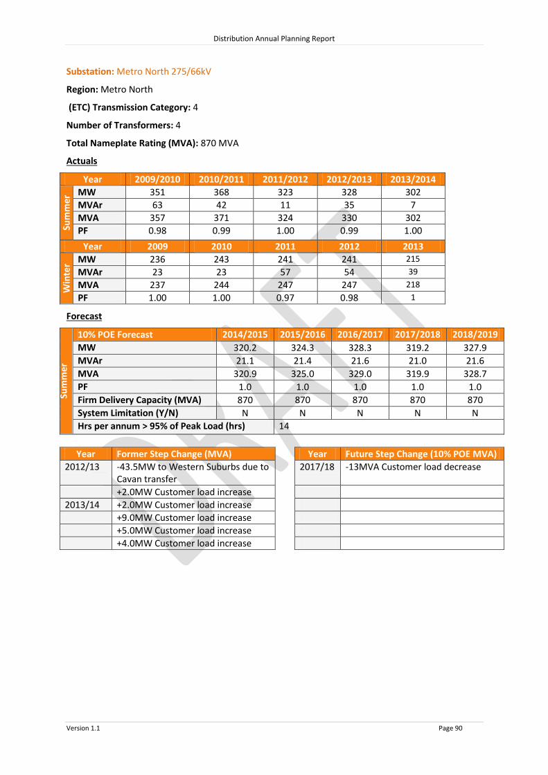
Distribution Annual Planning Report
Version 1.1 Page 90
Substation: Metro North 275/66kV
Region: Metro North
(ETC) Transmission Category: 4
Number of Transformers: 4
Total Nameplate Rating (MVA): 870 MVA
Actuals
Year 2009/2010 2010/2011 2011/2012 2012/2013 2013/2014
Sum
mer
MW 351 368 323 328 302
MVAr 63 42 11 35 7
MVA 357 371 324 330 302
PF 0.98 0.99 1.00 0.99 1.00
Year 2009 2010 2011 2012 2013
Win
ter MW 236 243 241 241 215
MVAr 23 23 57 54 39
MVA 237 244 247 247 218
PF 1.00 1.00 0.97 0.98 1
Forecast
Sum
mer
10% POE Forecast 2014/2015 2015/2016 2016/2017 2017/2018 2018/2019
MW 320.2 324.3 328.3 319.2 327.9
MVAr 21.1 21.4 21.6 21.0 21.6
MVA 320.9 325.0 329.0 319.9 328.7
PF 1.0 1.0 1.0 1.0 1.0
Firm Delivery Capacity (MVA) 870 870 870 870 870
System Limitation (Y/N) N N N N N
Hrs per annum > 95% of Peak Load (hrs) 14
Year Former Step Change (MVA) Year Future Step Change (10% POE MVA)
2012/13 -43.5MW to Western Suburbs due to Cavan transfer
2017/18 -13MVA Customer load decrease
+2.0MW Customer load increase
2013/14 +2.0MW Customer load increase
+9.0MW Customer load increase
+5.0MW Customer load increase
+4.0MW Customer load increase

Distribution Annual Planning Report
Version 1.1 Page 91
Substation: Angle Vale 66/11kV
Region: Metro North
Number of Feeders: 5
Number of Transformers: 3
Total Nameplate Rating (MVA): 22.5 MVA
Actuals
Year 2009/2010 2010/2011 2011/2012 2012/2013 2013/2014
Sum
mer
MW 17.9 16.6 15.1 15.2 17.4
MVAr 9.3 7.1 6.5 6.6 6.1
MVA 20.1 18.0 16.4 16.5 18.4
PF 0.89 0.92 0.92 0.92 0.94
Year 2009 2010 2011 2012 2013
Win
ter MW 9.2 11.6 10.6 10.4 10.6
MVAr 3.2 3.5 3.2 2.8 2.7
MVA 9.8 12.1 11.1 10.8 10.9
PF 0.94 0.96 0.96 0.97 0.97
Forecast
Sum
mer
10% POE Forecast 2014/2015 2015/2016 2016/2017 2017/2018 2018/2019
MW 14.9 15.2 15.4 15.7 16.0
MVAr 5.8 5.9 6.0 6.1 6.2
MVA 16.0 16.3 16.6 16.9 17.2
PF 0.93 0.93 0.93 0.93 0.93
Total Capacity (MVA) 27.3 27.3 27.3 27.3 27.3
50% POE Forecast
MW 13.7 14.0 14.3 14.6 14.9
MVAr 5.3 5.5 5.6 5.7 5.8
MVA 14.7
15.0
15.3
15.7
16.0 PF 0.93 0.93 0.93 0.93 0.93
Firm Delivery Capacity (MVA) 20.5 20.5 20.5 20.5 20.5
Transfer Capacity (MVA) 8.9
8.7
8.5
8.3
8.1 System Limitation (Y/N) N N N N N
Hrs per annum > 95% of Peak Load (hrs) 5
Year Former Step Change (MVA) Year Future Step Change (10% POE MVA)
2009/10 -3.0MVA to Virginia 2014/15 -2.5MVA to Smithfield West
2010/11 -1.1MVA to Penfield

Distribution Annual Planning Report
Version 1.1 Page 92
Substation: Direk 66/11kV
Region: Metro North
Number of Feeders: 8
Number of Transformers: 2
Total Nameplate Rating (MVA): 50 MVA
Actuals
Year 2009/2010 2010/2011 2011/2012 2012/2013 2013/2014
Sum
mer
MW 21.4 22.5 22.2 21.4 23.0
MVAr 9.5 7.6 8.5 8.4 7.2
MVA 23.4 23.7 23.7 23.0 24.1
PF 0.91 0.95 0.93 0.93 0.95
Year 2009 2010 2011 2012 2013
Win
ter MW 11.0 16.0 16.5 16.7 16.5
MVAr 2.4 3.6 3.4 4.5 3.8
MVA 11.2 16.4 16.9 17.2 17.0
PF 0.98 0.98 0.98 0.97 0.98
Forecast
Sum
mer
10% POE Forecast 2014/2015 2015/2016 2016/2017 2017/2018 2018/2019
MW 23.3 23.3 23.2 23.3 23.3
MVAr 8.2 8.2 8.1 8.2 8.2
MVA 24.7 24.7 24.6 24.7 24.7
PF 0.94 0.94 0.94 0.94 0.94
Total Capacity (MVA) 56.4 56.4 56.4 56.4 56.4
50% POE Forecast
MW 21.6 21.6 21.5 21.7 21.6
MVAr 7.6 7.6 7.6 7.6 7.6
MVA 22.9
22.9
22.8
23.0
22.9 PF 0.94 0.94 0.94 0.94 0.94
Firm Delivery Capacity (MVA) 29.8 29.8 29.8 29.8 29.8
Transfer Capacity (MVA) 8.1
8.0
8.0
7.9
7.9 System Limitation (Y/N) N N N N N
Hrs per annum > 95% of Peak Load (hrs) 9
Year Former Step Change (MVA) Year Future Step Change (10% POE MVA)
2009/10 +2.2MVA from Paralowie
+4.4MVA from Edinburgh
2011/12 +0.6MVA from Paralowie

Distribution Annual Planning Report
Version 1.1 Page 93
Substation: Edinburgh 66/11kV
Region: Metro North
Number of Feeders: 9
Number of Transformers: 3
Total Nameplate Rating (MVA): 75 MVA
Actuals
Year 2009/2010 2010/2011 2011/2012 2012/2013 2013/2014
Sum
mer
MW 24.8 24.3 18.9 16.7 15.2
MVAr 9.8 10.3 7.5 6.6 6.7
MVA 26.7 26.4 20.4 18.0 16.6
PF 0.93 0.92 0.93 0.93 0.92
Year 2009 2010 2011 2012 2013
Win
ter MW 19.8 28.7 19.3 14.6 12.9
MVAr 7.8 8.4 7.6 5.8 5.2
MVA 21.3 29.9 20.7 15.7 13.9
PF 0.93 0.96 0.93 0.93 0.93
Forecast
Sum
mer
10% POE Forecast 2014/2015 2015/2016 2016/2017 2017/2018 2018/2019
MW 16.6 16.7 16.8 8.2 8.3
MVAr 6.9 7.0 7.0 3.4 3.4
MVA 18.0 18.1 18.2 8.9 8.9
PF 0.92 0.92 0.92 0.92 0.92
Total Capacity (MVA) 84.4 84.4 84.4 84.4 84.4
50% POE Forecast
MW 15.8 15.9 16.0 7.4 7.4
MVAr 6.6 6.6 6.7 3.1 3.1
MVA 17.1
17.3
17.4
8.0
8.1 PF 0.92 0.92 0.92 0.92 0.92
Firm Delivery Capacity (MVA) 60.4 60.4 60.4 60.4 60.4
Transfer Capacity (MVA) 5.6
5.5
5.5
5.4
5.4 System Limitation (Y/N) N N N N N
Hrs per annum > 95% of Peak Load (hrs) 9
Year Former Step Change (MVA) Year Future Step Change (10% POE MVA)
2009/10 -4.4MVA to Direk 2017/18 -9.3MVA Customer load decrease
2011/12 -6.7MVA Customer load decrease

Distribution Annual Planning Report
Version 1.1 Page 94
Substation: Elizabeth Downs 66/11kV
Region: Metro North
Number of Feeders: 9
Number of Transformers: 2
Total Nameplate Rating (MVA): 50 MVA
Actuals
Year 2009/2010 2010/2011 2011/2012 2012/2013 2013/2014
Sum
mer
MW 38.9 40.4 38.3 40.4 43.6
MVAr 14.2 13.5 12.7 11.6 11.3
MVA 41.4 42.6 40.3 42.0 45.0
PF 0.94 0.95 0.95 0.96 0.97
Year 2009 2010 2011 2012 2013
Win
ter MW 26.0 29.2 28.9 30.5 29.7
MVAr 6.4 6.2 5.5 6.0 4.2
MVA 26.8 29.8 29.4 31.1 30.0
PF 0.97 0.98 0.98 0.98 0.99
Forecast
Sum
mer
10% POE Forecast 2014/2015 2015/2016 2016/2017 2017/2018 2018/2019
MW 39.2 40.4 41.6 42.8 44.1
MVAr 11.5 11.9 12.2 12.6 13.0
MVA 40.8 42.1 43.3 44.6 46.0
PF 0.96 0.96 0.96 0.96 0.96
Total Capacity (MVA) 59.6 59.6 59.6 59.6 59.6
50% POE Forecast
MW 35.3 36.3 37.5 38.6 39.8
MVAr 10.4 10.7 11.0 11.4 11.7
MVA 36.8
37.9
39.0
40.2
41.5 PF 0.96 0.96 0.96 0.96 0.96
Firm Delivery Capacity (MVA) 31.9 31.9 31.9 31.9 31.9
Transfer Capacity (MVA) 18.2
17.7
17.1
16.6
16.1 System Limitation (Y/N) N N N N N
Hrs per annum > 95% of Peak Load (hrs) 5
Year Former Step Change (MVA) Year Future Step Change (10% POE MVA)
2009/10 +1.0MVA from Penfield 2014/15 -7.3MVA to Smithfield West
*Within planning criteria risk margin

Distribution Annual Planning Report
Version 1.1 Page 95
Substation: Elizabeth Heights 66/11kV
Region: Metro North
Number of Feeders: 5
Number of Transformers: 2
Total Nameplate Rating (MVA): 20 MVA
Actuals
Year 2009/2010 2010/2011 2011/2012 2012/2013 2013/2014
Sum
mer
MW 20.7 20.5 17.0 17.9 18.6
MVAr 7.6 7.1 6.7 5.6 5.8
MVA 22.0 21.7 18.3 18.7 19.5
PF 0.94 0.94 0.93 0.96 0.95
Year 2009 2010 2011 2012 2013
Win
ter MW 15.2 15.4 14.0 14.1 13.3
MVAr 3.6 3.2 2.7 2.6 2.1
MVA 15.6 15.7 14.3 14.3 13.5
PF 0.97 0.98 0.98 0.98 0.99
Forecast
Sum
mer
10% POE Forecast 2014/2015 2015/2016 2016/2017 2017/2018 2018/2019
MW 19.2 19.3 19.4 19.6 19.6
MVAr 6.1 6.1 6.2 6.2 6.3
MVA 20.1 20.2 20.3 20.5 20.6
PF 0.95 0.95 0.95 0.95 0.95
Total Capacity (MVA) 27.6 27.6 27.6 27.6 27.6
50% POE Forecast
MW 17.3 17.4 17.6 17.8 17.8
MVAr 5.5 5.6 5.6 5.7 5.7
MVA 18.2
18.3
18.4
18.7
18.7 PF 0.95 0.95 0.95 0.95 0.95
Firm Delivery Capacity (MVA) 15.0 15.0 15.0 15.0 15.0
Transfer Capacity (MVA) 18.2
18.0
17.9
17.7
17.5 System Limitation (Y/N) N N N N N
Hrs per annum > 95% of Peak Load (hrs) 6
Year Former Step Change (MVA) Year Future Step Change (10% POE MVA)

Distribution Annual Planning Report
Version 1.1 Page 96
Substation: Elizabeth South - Residential 66/11kV
Region: Metro North
Number of Feeders: 7
Number of Transformers: 2
Total Nameplate Rating (MVA): 20 MVA
Actuals
Year 2009/2010 2010/2011 2011/2012 2012/2013 2013/2014
Sum
mer
MW 11.0 10.5 9.8 9.8 10.1
MVAr 3.4 0.0 3.2 3.3 2.9
MVA 11.5 10.5 10.4 10.3 10.5
PF 0.96 1.00 0.95 0.95 0.96
Year 2009 2010 2011 2012 2013
Win
ter MW 8.9 9.3 9.1 9.3 9.0
MVAr 1.9 1.9 1.5 1.5 1.1
MVA 9.1 9.5 9.2 9.4 9.0
PF 0.98 0.98 0.99 0.99 0.99
Forecast
Sum
mer
10% POE Forecast 2014/2015 2015/2016 2016/2017 2017/2018 2018/2019
MW 10.2 10.5 10.7 11.2 11.4
MVAr 3.5 3.6 3.7 3.8 3.9
MVA 10.8 11.1 11.3 11.8 12.0
PF 0.95 0.95 0.95 0.95 0.95
Total Capacity (MVA) 28.4 28.4 28.4 28.4 28.4
50% POE Forecast
MW 9.1
9.1
9.0
9.1
9.0 MVAr 3.0
3.0
3.0
3.0
3.0
MVA 9.6
9.6
9.5
9.6
9.5 PF 0.95
0.95
0.95
0.95
0.95
Firm Delivery Capacity (MVA) 15.0 15.0 15.0 15.0 15.0
Transfer Capacity (MVA) 12.3
12.4
12.4
12.5
12.5 System Limitation (Y/N) N N N N N
Hrs per annum > 95% of Peak Load (hrs) 5
Year Former Step Change (MVA) Year Future Step Change (10% POE MVA)

Distribution Annual Planning Report
Version 1.1 Page 97
Substation: Evanston 66/11kV
Region: Metro North
Number of Feeders: 6
Number of Transformers: 2
Total Nameplate Rating (MVA): 50 MVA
Actuals
Year 2009/2010 2010/2011 2011/2012 2012/2013 2013/2014
Sum
mer
MW 34.5 35.0 28.8 31.3 33.2
MVAr 13.6 13.9 11.1 12.1 11.4
MVA 37.1 37.7 30.9 33.6 35.2
PF 0.93 0.93 0.93 0.93 0.95
Year 2009 2010 2011 2012 2013
Win
ter MW 24.8 24.0 22.7 22.8 22.2
MVAr 6.7 6.6 5.5 5.5 5.0
MVA 25.7 24.9 23.4 23.5 22.7
PF 0.97 0.97 0.97 0.97 0.98
Forecast
Sum
mer
10% POE Forecast 2014/2015 2015/2016 2016/2017 2017/2018 2018/2019
MW 35.5 36.4 37.3 38.4 39.2
MVAr 2.7 3.0 3.3 3.6 3.9
MVA 35.6 36.5 37.4 38.6 39.4
PF 1.00 1.00 1.00 1.00 1.00
Total Capacity (MVA) 57.7 57.7 57.7 57.7 57.7
50% POE Forecast
MW 32.2 33.1 34.1 35.3 36.2
MVAr 1.6 1.9 2.2 2.6 2.9
MVA 32.2 33.2 34.2 35.4 36.3
PF 1.00 1.00 1.00 1.00 1.00
Firm Delivery Capacity (MVA) 30.5 30.5 30.5 30.5 30.5
Transfer Capacity (MVA) 4.9
4.8
4.6
4.4
4.3 System Limitation (Y/N) N N N Y* Y*
Hrs per annum > 95% of Peak Load (hrs) 6
Year Former Step Change (MVA) Year Future Step Change (10% POE MVA)
2014/15 9MVAr capacitor bank installed
*Within planning criteria risk margin

Distribution Annual Planning Report
Version 1.1 Page 98
Substation: Parafield Gardens 66/11kV
Region: Metro North
Number of Feeders: 6
Number of Transformers: 2
Total Nameplate Rating (MVA): 64 MVA
Actuals
Year 2009/2010 2010/2011 2011/2012 2012/2013 2013/2014
Sum
mer
MW 22.4 19.6 16.5 16.6 17.8
MVAr 8.7 6.7 5.7 5.1 4.4
MVA 24.0 20.7 17.5 17.4 18.4
PF 0.93 0.95 0.94 0.96 0.97
Year 2009 2010 2011 2012 2013
Win
ter MW 14.6 15.1 12.7 12.2 10.9
MVAr 3.9 3.5 2.8 2.2 1.8
MVA 15.1 15.5 13.0 12.4 11.1
PF 0.97 0.97 0.98 0.98 0.99
Forecast
Sum
mer
10% POE Forecast 2014/2015 2015/2016 2016/2017 2017/2018 2018/2019
MW 24.5 25.1 25.8 26.6 32.4
MVAr 7.5 7.7 7.9 8.1 9.9
MVA 25.6 26.3 27.0 27.8 33.9
PF 0.96 0.96 0.96 0.96 0.96
Total Capacity (MVA) 70.2 70.2 70.2 70.2 70.2
50% POE Forecast
MW 22.6 23.3 24.0 24.8 30.7
MVAr 6.9 7.1 7.3 7.6 9.4
MVA 23.7
24.3
25.1
25.9
32.1 PF 0.96 0.96 0.96 0.96 0.96
Firm Delivery Capacity (MVA) 38.1 38.1 38.1 38.1 38.1
Transfer Capacity (MVA) 7.0
6.9
6.7
6.6
6.5 System Limitation (Y/N) N N N N N
Hrs per annum > 95% of Peak Load (hrs) 5
Year Former Step Change (MVA) Year Future Step Change (10% POE MVA)
2010/11 -1.0MVA to Paralowie 2014/15 +4.6MVA from Cavan
-2.3MVA to Salisbury 2018/19 +5.0MVA from Cavan

Distribution Annual Planning Report
Version 1.1 Page 99
Substation: Paralowie 66/11kV
Region: Metro North
Number of Feeders: 4
Number of Transformers: 2
Total Nameplate Rating (MVA): 20 MVA
Actuals
Year 2009/2010 2010/2011 2011/2012 2012/2013 2013/2014
Sum
mer
MW 21.7 17.9 15.4 16.9 16.7
MVAr 8.3 6.3 5.4 2.3 1.3
MVA 23.2 19.0 16.3 17.1 16.7
PF 0.93 0.94 0.94 0.99 1.00
Year 2009 2010 2011 2012 2013
Win
ter MW 15.4 14.1 11.5 11.4 12.7
MVAr 3.9 3.1 2.4 2.4 2.3
MVA 15.9 14.5 11.7 11.6 12.9
PF 0.97 0.98 0.98 0.98 0.98
Forecast
Sum
mer
10% POE Forecast 2014/2015 2015/2016 2016/2017 2017/2018 2018/2019
MW 17.4 17.5 17.7 18.0 18.2
MVAr 3.8 3.8 3.8 3.9 3.9
MVA 17.8 17.9 18.1 18.4 18.6
PF 0.98 0.98 0.98 0.98 0.98
Total Capacity (MVA) 27.5 27.5 27.5 27.5 27.5
50% POE Forecast
MW 16.2 16.5 16.8 17.2 17.5
MVAr 3.5 3.6 3.6 3.7 3.8
MVA 16.6 16.9 17.2 17.6 17.9
PF 0.98 0.98 0.98 0.98 0.98
Firm Delivery Capacity (MVA) 14.2 14.2 14.2 14.2 14.2
Transfer Capacity (MVA) 12.9
12.5
12.2
11.9
11.6 System Limitation (Y/N) N N N N N
Hrs per annum > 95% of Peak Load (hrs) 5
Year Former Step Change (MVA) Year Future Step Change (10% POE MVA)
2009/10 -2.2MVA to Direk
2010/11 -2.7MVA to Salisbury
+1.0MVA from Parafield Gardens
2011/12 -0.6MVA to Direk
2012/13 9MVAr capacitor bank installed

Distribution Annual Planning Report
Version 1.1 Page 100
Substation: Penfield 66/11kV
Region: Metro North
Number of Feeders: 8
Number of Transformers: 2
Total Nameplate Rating (MVA): 50 MVA
Actuals
Year 2009/2010 2010/2011 2011/2012 2012/2013 2013/2014
Sum
mer
MW 32.3 33.4 27.9 30.9 31.4
MVAr 12.7 13.3 11.4 11.9 10.7
MVA 34.7 36.0 30.2 33.1 33.2
PF 0.93 0.93 0.93 0.93 0.95
Year 2009 2010 2011 2012 2013
Win
ter MW 22.3 22.6 24.1 21.3 21.9
MVAr 8.1 7.8 0.0 7.2 6.5
MVA 23.7 24.0 24.1 22.5 22.9
PF 0.94 0.95 1.00 0.95 0.96
Forecast
Sum
mer
10% POE Forecast 2014/2015 2015/2016 2016/2017 2017/2018 2018/2019
MW 26.3 26.9 27.5 28.1 28.7
MVAr 10.0 10.2 10.4 10.6 10.9
MVA 28.1 28.7 29.4 30.0 30.7
PF 0.94 0.94 0.94 0.94 0.94
Total Capacity (MVA) 56.2 56.2 56.2 56.2 56.2
50% POE Forecast
MW 24.5 25.0 25.5 26.1 26.6
MVAr 9.3 9.5 9.7 9.9 10.1
MVA 26.2
26.7
27.3
27.9
28.5 PF 0.94 0.94 0.94 0.94 0.94
Firm Delivery Capacity (MVA) 29.8 29.8 29.8 29.8 29.8
Transfer Capacity (MVA) 8.3
8.1
7.9
7.8
7.6 System Limitation (Y/N) N N N N N
Hrs per annum > 95% of Peak Load (hrs) 9
Year Former Step Change (MVA) Year Future Step Change (10% POE MVA)
2009/10 -1.0MVA to Elizabeth Downs 2014/15 -7.1MVA to Smithfield West
2010/11 +1.1MVA from Angle Vale

Distribution Annual Planning Report
Version 1.1 Page 101
Substation: Salisbury 66/11kV
Region: Metro North
Number of Feeders: 10
Number of Transformers: 3
Total Nameplate Rating (MVA): 63 MVA
Actuals
Year 2009/2010 2010/2011 2011/2012 2012/2013 2013/2014
Sum
mer
MW 60.6 57.2 51.0 54.3 56.6
MVAr 7.8 11.6 4.1 3.0 1.6
MVA 61.1 58.4 51.1 54.4 56.6
PF 0.99 0.98 1.00 1.00 1.00
Year 2009 2010 2011 2012 2013
Win
ter MW 42.9 38.7 41.6 39.7 39.0
MVAr 0.9 2.2 4.7 3.6 2.8
MVA 42.9 38.8 41.8 39.8 39.1
PF 1.00 1.00 0.99 1.00 1.00
Forecast
Sum
mer
10% POE Forecast 2014/2015 2015/2016 2016/2017 2017/2018 2018/2019
MW 57.5 57.6 57.6 58.0 58.0
MVAr 3.1 3.1 3.1 3.1 3.1
MVA 57.6 57.7 57.7 58.1 58.1
PF 1.00 1.00 1.00 1.00 1.00
Total Capacity (MVA) 72.6 72.6 72.6 72.6 72.6
50% POE Forecast
MW 52.7 52.7 52.6 53.0 52.9
MVAr 2.8 2.8 2.8 2.9 2.9
MVA 52.7 52.7 52.7 53.1 53
PF 1.00 1.00 1.00 1.00 1.00
Firm Delivery Capacity (MVA) 49.5 49.5 49.5 49.5 49.5
Transfer Capacity (MVA) 20.9
20.9
20.8
20.8
20.7 System Limitation (Y/N) N N N N N
Hrs per annum > 95% of Peak Load (hrs) 7
Year Former Step Change (MVA) Year Future Step Change (10% POE MVA)
2010/11 +2.7MVA from Paralowie
+2.3MVA from Parafield Gardens
+1.85MVA from Ingle Farm
-5MVA customer load decrease

Distribution Annual Planning Report
Version 1.1 Page 102
Substation: Smithfield West 66/11kV
Region: Metro North
Number of Feeders: 3
Number of Transformers: 1
Total Nameplate Rating (MVA): 32 MVA
Actuals
Year 2009/2010 2010/2011 2011/2012 2012/2013 2013/2014
Sum
mer
MW N/A N/A N/A N/A N/A
MVAr N/A N/A N/A N/A N/A
MVA N/A N/A N/A N/A N/A
PF N/A N/A N/A N/A N/A
Year 2009 2010 2011 2012 2013
Win
ter MW N/A N/A N/A N/A N/A
MVAr N/A N/A N/A N/A N/A
MVA N/A N/A N/A N/A N/A
PF N/A N/A N/A N/A N/A
Forecast
Sum
mer
10% POE Forecast 2014/2015 2015/2016 2016/2017 2017/2018 2018/2019
MW 16.2 16.6 16.9 17.3 17.7
MVAr 4.9 5.0 5.1 5.2 5.4
MVA 16.9 17.3 17.7 18.1 18.5
PF 0.96 0.96 0.96 0.96 0.96
Total Capacity (MVA) 36.2 36.2 36.2 36.2 36.2
50% POE Forecast
MW 14.5 14.9 15.3 15.7 16.1
MVAr 4.4 4.5 4.6 4.7 4.9
MVA 15.2 15.6 16 16.4 16.8
PF 0.96 0.96 0.96 0.96 0.96
Firm Delivery Capacity (MVA) 0.0 0.0 0.0 0.0 0.0
Transfer Capacity (MVA) 14.5
14.7
14.8
14.9
15.0 System Limitation (Y/N) Y* Y* Y* Y* Y*
Hrs per annum > 95% of Peak Load (hrs) 5
Year Former Step Change (MVA) Year Future Step Change (10% POE MVA)
2014/15 +2.5MVA from Angle Vale
2014/15 +7.3MVA from Elizabeth Downs
2014/15 +7.1MVA from Penfield
*Within planning criteria risk margin

Distribution Annual Planning Report
Version 1.1 Page 103
Substation: Two Wells 66/11kV
Region: Metro North
Number of Feeders: 1
Number of Transformers: 1
Total Nameplate Rating (MVA): 12.5 MVA
Actuals
Year 2009/2010 2010/2011 2011/2012 2012/2013 2013/2014
Sum
mer
MW N/A N/A N/A N/A N/A
MVAr N/A N/A N/A N/A N/A
MVA N/A N/A N/A N/A N/A
PF N/A N/A N/A N/A N/A
Year 2009 2010 2011 2012 2013
Win
ter MW N/A N/A N/A N/A N/A
MVAr N/A N/A N/A N/A N/A
MVA N/A N/A N/A N/A N/A
PF N/A N/A N/A N/A N/A
Forecast
Sum
mer
10% POE Forecast 2014/2015 2015/2016 2016/2017 2017/2018 2018/2019
MW N/A 4.2 4.3 4.3 4.4
MVAr N/A 2.0 2.1 2.1 2.1
MVA N/A 4.7 4.7 4.8 4.9
PF N/A 0.90 0.90 0.90 0.90
Total Capacity (MVA) N/A 14.9 14.9 14.9 14.9
50% POE Forecast
MW N/A 3.8 3.8 3.9 3.9
MVAr N/A 1.8 1.9 1.9 1.9
MVA N/A 4.2 4.2 4.3 4.3
PF N/A 0.90 0.90 0.90 0.90
Firm Delivery Capacity (MVA) N/A 0.0 0.0 0.0 0.0
Transfer Capacity (MVA) N/A 3.4 3.3 3.3 3.3
System Limitation (Y/N) N/A Y* Y* Y* Y*
Hrs per annum > 95% of Peak Load (hrs) 5
Year Former Step Change (MVA) Year Future Step Change (10% POE MVA)
2015/16 +4.7MVA from Virginia
*Within planning criteria risk margin

Distribution Annual Planning Report
Version 1.1 Page 104
Substation: Virginia 66/11kV
Region: Metro North
Number of Feeders: 3
Number of Transformers: 1
Total Nameplate Rating (MVA): 12.5 MVA
Actuals
Year 2009/2010 2010/2011 2011/2012 2012/2013 2013/2014
Sum
mer
MW 10.0 9.0 9.0 9.0 9.8
MVAr 5.0 5.0 5.0 4.0 4.2
MVA 11.2 10.3 10.3 9.8 10.6
PF 0.89 0.87 0.87 0.91 0.92
Year 2009 2010 2011 2012 2013
Win
ter MW 5.0 6.0 6.0 6.0 5.0
MVAr 2.0 2.0 2.0 2.0 1.0
MVA 5.4 6.3 6.3 6.3 5.1
PF 0.93 0.95 0.95 0.95 0.98
Forecast
Sum
mer
10% POE Forecast 2014/2015 2015/2016 2016/2017 2017/2018 2018/2019
MW 9.3 5.1 5.2 5.3 5.4
MVAr 4.5 2.5 2.5 2.6 2.6
MVA 10.3 5.7 5.8 5.9 5.9
PF 0.90 0.90 0.90 0.90 0.90
Total Capacity (MVA) 14.9 14.9 14.9 14.9 14.9
50% POE Forecast
MW 8.4
4.7 4.7 4.8 4.8
MVAr 4.1
2.3 2.3 2.3 2.3
MVA 9.3
5.2 5.2 5.3 5.3
PF 0.90
0.90
0.90
0.90
0.90 Firm Delivery Capacity (MVA) 0.0 0.0 0.0 0.0 0.0
Transfer Capacity (MVA) 5.0
7.1
7.0
6.9
6.8 System Limitation (Y/N) Y* N N N N
Hrs per annum > 95% of Peak Load (hrs) 5
Year Former Step Change (MVA) Year Future Step Change (10% POE MVA)
2009/10 +3.0MVA from Angle Vale 2015/16 -4.7MVA to Two Wells
*Solved by transfer to Two Wells Substation in 2015/16

Distribution Annual Planning Report
Version 1.1 Page 105
8.6 Southern Suburbs Regional Development Plan
The Southern Suburbs
The SA Power Networks’ Southern Suburbs Region includes the region from Glenelg North to the West extending north-west to North Unley, south-west to Aldinga, and south to Willunga, from where it supplies the Fleurieu region. There are four main connection points in the Southern Suburbs, being City West, Magill, Morphett Vale East and Happy Valley. SA Power Networks’ Distribution Network Electricity is supplied throughout the Southern Suburbs via Zone Substations. These Zone Substations are operated at 66,000 Volts stepped down to 11,000 Volts. Customers are supplied from SA Power Networks’ distribution system via 11kV feeders, which are connected to distribution substations. These feeders are extended and upgraded as required to meet customer demand and customer connection requests. Large customer projects may require a distribution substation upgrade as well as feeder modifications, therefore SA Power Networks should be notified as early as possible during the planning stages of a project so that customer connection requirements can be met. There are no system limitations forecast for the primary distribution feeders under normal conditions in the Southern Suburbs in the next two years.
8.6.1 Southern Suburbs SCADA Substations
Source Connection Point Associated SCADA Substations
Southern Suburbs Meshed 66kV Network:
City West – South
Happy Valley
Magill – Transformer 1 Morphett Vale East
Aldinga
Ascot Park
Blackwood
Clarence Gardens
Clarendon
Cudmore Park
Glenelg North
Hackham
Happy Valley 11kV
Keswick
Kingswood
Lower Mitcham
McLaren Flat
McLaren Vale
Morphett Vale East 11kV
Morphettville
Noarlunga Centre
North Unley
Oaklands
Panorama
Plympton
Port Noarlunga
Port Stanvac
Seacombe
Seaford
Sheidow Park
Tonsley Park
Willunga 33kV
Willunga 11kV

SHEIDOW PARK
MORPHETT VALE EAST
SAW HAPPY VALLEY
SEACOMBE
MORPHETTVILLE
GLENELG NORTH
PORT STANVAC
OAKLANDS
TONSLEY PARK
CUDMORE PARK
ASCOT PARK
PLYMPTON
CITYWEST
HAPPY VALLEY
CLARENDON
LONSDALE
CHERRY GARDENS (ENET)
BLACKWOOD
CLARENCE GARDENS
PANORAMA
LOWER MITCHAM
KESWICKNORTH UNLEY
KINGSWOOD
WILLUNGA
NOARLUNGACENTRE
ALDINGA
SEAFORD
McLAREN VALE
McLAREN FLAT
HACKHAM
PORT NOARLUNGA
Legend275kV Transmission Line132kV Transmission Line66kV Sub Transmission Line33kV Sub Transmission LineSubstation
0.0 1.5 3.0 4.5 6.0
Kilometres
SOUTHERNSUBURBS
System Limitation.

Distribution Annual Planning Report
Version 1.1 Page 107
Substation: Metro South 275/66kV
Region: Metro South
(ETC) Transmission Category: 4
Number of Transformers: 7
Total Nameplate Rating (MVA): 1515 MVA
Actuals*
Year 2009/2010 2010/2011 2011/2012 2012/2013 2013/2014
Sum
mer
MW 711 728 616 676 765
MVAr 19 46 40 87 101
MVA 712 729 618 682 772
PF 1.00 1.00 1.00 0.99 0.99
Year 2009 2010 2011 2012 2013
Win
ter MW 512 544 538 527 507
MVAr 64 73 65.9 115 97
MVA 516 549 542 540 516
PF 0.99 0.99 0.99 0.98 1
Forecast^
Sum
mer
10% POE Forecast 2014/2015 2015/2016 2016/2017 2017/2018 2018/2019
MW 666.2 631.9 633.8 634.8 635.9
MVAr 105.3 99.9 100.1 100.3 100.5
MVA 674.5 639.8 641.6 642.7 643.8
PF 0.99 0.99 0.99 0.99 0.99
Firm Delivery Capacity (MVA) 1227 1227 1227 1227 1227
System Limitation (Y/N) N N N N N
Hrs per annum > 95% of Peak Load (hrs) 3
Year Former Step Change (MVA) Year Future Step Change (10% POE MVA)
2009/10 +11.0MVA Customer load increase 2014/15 -43.5MW to Eastern Suburbs due to Linden Park transfer
2011/12 +6.0MVA Customer load increase 2015/16 -50.0MW Customer load decrease
2012/13 +49.0MW Customer load increase
*Potential Impact of below embedded generation has been removed from the above Actuals: (i.e. generation output = 0)
21MW of diesel export generation at 11kV
34MW of wind export generation at 33kV (located within Fleurieu Region)
65MW of diesel export generation at 66kV
2MW of dump export generation at 11kV ^Impact of below embedded generation excluded from Forecast: (generation output = 0)
21MW of diesel export generation at 11kV
34MW of wind export generation at 33kV (located within Fleurieu Region)
65MW of diesel export generation at 66kV ^Impact of below embedded generation included in the Forecast: (generation output = up to
2MW)
2MW of dump export generation at 11kV

Distribution Annual Planning Report
Version 1.1 Page 108
Substation: Aldinga 66/11kV
Region: Metro South
Number of Feeders: 4
Number of Transformers: 2
Total Nameplate Rating (MVA): 25 MVA
Actuals
Year 2009/2010 2010/2011 2011/2012 2012/2013 2013/2014
Sum
mer
MW 13.8 16.0 15.4 15.9 18.3
MVAr 7.4 5.1 4.4 4.5 4.7
MVA 15.7 16.8 16.0 16.6 18.9
PF 0.88 0.95 0.96 0.96 0.97
Year 2009 2010 2011 2012 2013
Win
ter MW 10.8 11.1 7.9 12.8 12.3
MVAr 2.4 2.4 1.7 2.7 1.9
MVA 11.0 11.4 8.1 13.1 12.4
PF 0.98 0.98 0.98 0.98 0.99
Forecast
Sum
mer
10% POE Forecast 2014/2015 2015/2016 2016/2017 2017/2018 2018/2019
MW 17.8 18.8 19.7 20.6 21.5
MVAr 4.9 5.2 5.5 5.7 6.0
MVA 18.5 19.5 20.5 21.4 22.3
PF 0.96 0.96 0.96 0.96 0.96
Total Capacity (MVA) 33.2 33.2 33.2 33.2 33.2
50% POE Forecast
MW 15.5 16.3 17.1 17.9 18.7
MVAr 4.3 4.5 4.8 5.0 5.2
MVA 16.1
16.9
17.8
18.6
19.4 PF 0.96 0.96 0.96 0.96 0.96
Firm Delivery Capacity (MVA) 17.7 17.7 17.7 17.7 17.7
Transfer Capacity (MVA) 2.0
1.9
1.9
1.8
1.8 System Limitation (Y/N) N N N N N
Hrs per annum > 95% of Peak Load (hrs) 5
Year Former Step Change (MVA) Year Future Step Change (10% POE MVA)
2009/10 -0.3MVA to Myponga
+0.3 MVA Customer load increase
-1.0 MVA to Seaford
2010/11 +1.0 MVA from Seaford
+1.0 MVA Customer load increase
2011/12 +1.0 MVA Customer load increase

Distribution Annual Planning Report
Version 1.1 Page 109
Substation: Ascot Park 66/11kV
Region: Metro South
Number of Feeders: 6
Number of Transformers: 1
Total Nameplate Rating (MVA): 21 MVA
Actuals
Year 2009/2010 2010/2011 2011/2012 2012/2013 2013/2014
Sum
mer
MW 22.4 23.5 19.6 19.3 21.0
MVAr 8.0 8.2 6.3 6.3 5.6
MVA 23.8 24.9 20.6 20.3 21.7
PF 0.94 0.94 0.95 0.95 0.97
Year 2009 2010 2011 2012 2013
Win
ter MW 16.3 18.5 16.4 16.1 15.9
MVAr 4.4 4.4 3.9 3.9 3.0
MVA 16.9 19.0 16.9 16.6 16.2
PF 0.97 0.97 0.97 0.97 0.98
Forecast
Sum
mer
10% POE Forecast 2014/2015 2015/2016 2016/2017 2017/2018 2018/2019
MW 19.1 19.4 19.8 20.1 20.4
MVAr 5.7 5.8 5.9 6.0 6.1
MVA 19.9 20.3 20.7 21.0 21.3
PF 0.96 0.96 0.96 0.96 0.96
Total Capacity (MVA) 27.0 27.0 27.0 27.0 27.0
50% POE Forecast
MW 16.4 16.8 17.1 17.4 17.8
MVAr 4.9 5.0 5.1 5.2 5.3
MVA 17.2
17.5
17.9
18.2
18.5 PF 0.96 0.96 0.96 0.96 0.96
Firm Delivery Capacity (MVA) 0.0 0.0 0.0 0.0 0.0
Transfer Capacity (MVA) 16.2
16.0
15.8
15.6
15.4 System Limitation (Y/N) Y* Y* Y* Y* Y
Hrs per annum > 95% of Peak Load (hrs) 7
Year Former Step Change (MVA) Year Future Step Change (10% POE MVA)
2011/12 +3.4MVA from Morphettville
-3.8MVA to Tonsley Park
2012/13 -1.9MVA to Clarence Gardens
*Within planning criteria risk margin

Distribution Annual Planning Report
Version 1.1 Page 110
Ascot Park 66/11kV Substation
System Limitation
Ascot Park 66/11kV Substation has one 21MVA 66/11kV transformer and is located in the Southern Suburb.
In the summer of 2018/19, up to 3.1MVA of customer load is forecasted to be unsupplied during a contingent event after all available load transfers have been implemented.
Potential solutions that address the system limitation include:
Improve available transfers from Ascot Park Substation to adjacent substations by construct new feeder exit and feeder ties (preferred option); or
Upgrade the Ascot Park Substation with a second transformer; or
Power factor correction to reduce the load on the transformer.
Due to the extent of the overload during a contingent event, PF correction would not defer this system limitation for at least a 12 months period.
A RIT-D is not expected to be required for this system limitation.

Distribution Annual Planning Report
Version 1.1 Page 111
Substation: Blackwood 66/11kV
Region: Metro South
Number of Feeders: 5
Number of Transformers: 2
Total Nameplate Rating (MVA): 50 MVA
Actuals
Year 2009/2010 2010/2011 2011/2012 2012/2013 2013/2014
Sum
mer
MW 26.6 28.4 23.9 24.6 27.9
MVAr 10.1 10.3 8.1 7.3 7.7
MVA 28.5 30.2 25.3 25.7 28.9
PF 0.94 0.94 0.95 0.96 0.96
Year 2009 2010 2011 2012 2013
Win
ter MW 21.4 23.0 21.0 20.8 21.0
MVAr 5.7 6.2 4.9 4.4 3.8
MVA 22.2 23.8 21.5 21.3 21.3
PF 0.97 0.97 0.97 0.98 0.98
Forecast
Sum
mer
10% POE Forecast 2014/2015 2015/2016 2016/2017 2017/2018 2018/2019
MW 25.1 25.1 25.1 25.0 24.9
MVAr 7.6 7.6 7.6 7.6 7.6
MVA 26.3 26.2 26.2 26.1 26.0
PF 0.96 0.96 0.96 0.96 0.96
Total Capacity (MVA) 57.9 57.9 57.9 57.9 57.9
50% POE Forecast
MW 21.5 21.2 20.9 20.6 20.3
MVAr 6.6 6.5 6.4 6.3 6.2
MVA 22.5
22.2
21.9
21.5
21.2 PF 0.96 0.96 0.96 0.96 0.96
Firm Delivery Capacity (MVA) 30.5 30.5 30.5 30.5 30.5
Transfer Capacity (MVA) 2.7
2.8
2.8
2.9
3.0 System Limitation (Y/N) N N N N N
Hrs per annum > 95% of Peak Load (hrs) 6
Year Former Step Change (MVA) Year Future Step Change (10% POE MVA)

Distribution Annual Planning Report
Version 1.1 Page 112
Substation: Clarence Gardens 66/11kV
Region: Metro South
Number of Feeders: 5
Number of Transformers: 1
Total Nameplate Rating (MVA): 32 MVA
Actuals
Year 2009/2010 2010/2011 2011/2012 2012/2013 2013/2014
Sum
mer
MW 10.2 10.6 9.0 8.8 18.9
MVAr 4.7 4.7 4.1 3.2 5.2
MVA 11.2 11.6 9.9 9.4 19.6
PF 0.91 0.91 0.91 0.94 0.96
Year 2009 2010 2011 2012 2013
Win
ter MW 8.3 12.6 7.4 7.5 7.5
MVAr 2.5 3.6 2.2 1.9 1.7
MVA 8.6 13.1 7.7 7.7 7.7
PF 0.96 0.96 0.96 0.97 0.97
Forecast
Sum
mer
10% POE Forecast 2014/2015 2015/2016 2016/2017 2017/2018 2018/2019
MW 17.3 17.3 17.4 17.4 17.4
MVAr 6.4 6.5 6.5 6.5 6.5
MVA 18.4 18.5 18.5 18.6 18.6
PF 0.94 0.94 0.94 0.94 0.94
Total Capacity (MVA) 36.2 36.2 36.2 36.2 36.2
50% POE Forecast
MW 14.9 14.9 14.9 14.9 14.9
MVAr 5.6 5.6 5.6 5.6 5.6
MVA 15.9
15.9
16.0
15.9
15.9 PF 0.94 0.94 0.94 0.94 0.94
Firm Delivery Capacity (MVA) 0.0 0.0 0.0 0.0 0.0
Transfer Capacity (MVA) 17.9
18.0
18.1
18.1
18.2 System Limitation (Y/N) N N N N N
Hrs per annum > 95% of Peak Load (hrs) 6
Year Former Step Change (MVA) Year Future Step Change (10% POE MVA)
2012/13 +1.9MVA from Ascot Park
+2.2MVA from Keswick
+3.8MVA from Kingswood
+1.3MVA from Plympton

Distribution Annual Planning Report
Version 1.1 Page 113
Substation: Clarendon 66/11kV
Region: Metro South
Number of Feeders: 2
Number of Transformers: 1
Total Nameplate Rating (MVA): 2.5 MVA
Actuals
Year 2009/2010 2010/2011 2011/2012 2012/2013 2013/2014
Sum
mer
MW 3.3 3.2 2.9 2.6 3.2
MVAr 1.6 1.4 1.3 1.0 1.1
MVA 3.7 3.5 3.2 2.8 3.4
PF 0.90 0.91 0.92 0.94 0.95
Year 2009 2010 2011 2012 2013
Win
ter MW 2.5 2.7 2.5 2.5 2.4
MVAr 0.6 0.7 0.5 0.3 0.2
MVA 2.6 2.8 2.6 2.6 2.4
PF 0.97 0.97 0.98 0.99 1.00
Forecast
Sum
mer
10% POE Forecast 2014/2015 2015/2016 2016/2017 2017/2018 2018/2019
MW 2.7 2.7 2.8 2.8 2.8
MVAr 1.0 1.0 1.0 1.0 1.0
MVA 2.8 2.9 2.9 3.0 3.0
PF 0.94 0.94 0.94 0.94 0.94
Total Capacity (MVA) 3.3 3.3 3.3 3.3 3.3
50% POE Forecast
MW 2.3 2.4 2.4 2.4 2.5
MVAr 0.9 0.9 0.9 0.9 0.9
MVA 2.5
2.5
2.6
2.6
2.6 PF 0.94 0.94 0.94 0.94 0.94
Firm Delivery Capacity (MVA) 0.0 0.0 0.0 0.0 0.0
Transfer Capacity (MVA) 1.9
1.9
1.9
1.9
1.9 System Limitation (Y/N) N N N N N
Hrs per annum > 95% of Peak Load (hrs) 2
Year Former Step Change (MVA) Year Future Step Change (10% POE MVA)
2011/12 -0.4MVA to McLaren Flat

Distribution Annual Planning Report
Version 1.1 Page 114
Clarendon 66/11kV Substation
System Limitation
Clarendon 66/11kV Substation has one 2.5MVA 66/11kV transformer and is located near the township of Clarendon.
In the summer of 2013/14, the substation transformer was overloaded by 0.1MVA above its total capacity and 0.9MVA above its nameplate rating. While the 10% POE load forecast does not exceed the published total capacity above, the transformer is approaching 50 years of age and its total capacity is expected to reduce.
Potential solutions that address the system limitation include:
Upgrade 11kV feeder ties and transfer load to a nearby substation (preferred option); or
Upgrade the Clarendon Substation with a newer larger transformer or a second transformer; or
Power factor correction to reduce the load on the transformer.
1.5MVAR of power factor correction or a load transfer of 0.3MVA would defer this system limitation for at least a 12 month period.
A RIT-D is not expected to be required for this system limitation.

Distribution Annual Planning Report
Version 1.1 Page 115
Substation: Cudmore Park 66/11kV
Region: Metro South
Number of Feeders: 5
Number of Transformers: 2
Total Nameplate Rating (MVA): 20 MVA
Actuals
Year 2009/2010 2010/2011 2011/2012 2012/2013 2013/2014
Sum
mer
MW 16.9 18.2 17.1 16.0 16.7
MVAr 8.5 9.0 8.5 8.3 8.3
MVA 18.9 20.3 19.1 18.0 18.6
PF 0.89 0.90 0.90 0.89 0.90
Year 2009 2010 2011 2012 2013
Win
ter MW 14.1 15.6 14.1 14.1 13.3
MVAr 6.3 7.0 6.4 6.0 5.7
MVA 15.5 17.1 15.5 15.3 14.5
PF 0.91 0.91 0.91 0.92 0.92
Forecast
Sum
mer
10% POE Forecast 2014/2015 2015/2016 2016/2017 2017/2018 2018/2019
MW 15.9 15.6 15.4 15.1 14.8
MVAr 7.9 7.8 7.6 7.5 7.4
MVA 17.7 17.5 17.2 16.8 16.5
PF 0.90 0.90 0.90 0.90 0.90
Total Capacity (MVA) 22.1 22.1 22.1 22.1 22.1
50% POE Forecast
MW 14.5 14.1 13.8 13.4 13.1
MVAr 7.2 7.0 6.9 6.7 6.5
MVA 16.2
15.8
15.4
15.0
14.6 PF 0.90 0.90 0.90 0.90 0.90
Firm Delivery Capacity (MVA) 13.0 13.0 13.0 13.0 13.0
Transfer Capacity (MVA) 6.0
6.3
6.5
6.7
6.9 System Limitation (Y/N) N N N N N
Hrs per annum > 95% of Peak Load (hrs) 9
Year Former Step Change (MVA) Year Future Step Change (10% POE MVA)
2011/12 +1.1MVA from Panorama

Distribution Annual Planning Report
Version 1.1 Page 116
Substation: Glenelg North 66/11kV
Region: Metro South
Number of Feeders: 6
Number of Transformers: 2
Total Nameplate Rating (MVA): 20 MVA
Actuals
Year 2009/2010 2010/2011 2011/2012 2012/2013 2013/2014
Sum
mer
MW 22.0 21.6 16.4 15.2 17.3
MVAr 9.5 9.0 6.8 6.0 6.5
MVA 24.0 23.4 17.7 16.3 18.5
PF 0.92 0.92 0.92 0.93 0.94
Year 2009 2010 2011 2012 2013
Win
ter MW 15.9 17.0 14.4 12.2 11.5
MVAr 6.2 6.1 4.6 3.6 3.2
MVA 17.0 18.1 15.1 12.7 11.9
PF 0.93 0.94 0.95 0.96 0.96
Forecast
Sum
mer
10% POE Forecast 2014/2015 2015/2016 2016/2017 2017/2018 2018/2019
MW 15.8 16.1 16.3 16.5 16.7
MVAr 6.3 6.4 6.5 6.5 6.6
MVA 17.0 17.3 17.5 17.8 18.0
PF 0.93 0.93 0.93 0.93 0.93
Total Capacity (MVA) 27.9 27.9 27.9 27.9 27.9
50% POE Forecast
MW 13.9 14.2 14.5 14.7 15.0
MVAr 5.5 5.6 5.7 5.8 5.9
MVA 15.0
15.3
15.6
15.8
16.1 PF 0.93 0.93 0.93 0.93 0.93
Firm Delivery Capacity (MVA) 15.0 15.0 15.0 15.0 15.0
Transfer Capacity (MVA) 5.6
5.5
5.5
5.4
5.4 System Limitation (Y/N) N N N N N
Hrs per annum > 95% of Peak Load (hrs) 7
Year Former Step Change (MVA) Year Future Step Change (10% POE MVA)
2011/12 -3.0MVA to Plympton
-3.6MVA to Morphettville

Distribution Annual Planning Report
Version 1.1 Page 117
Substation: Hackham 66/11kV
Region: Metro South
Number of Feeders: 3
Number of Transformers: 1
Total Nameplate Rating (MVA): 25 MVA
Actuals
Year 2009/2010 2010/2011 2011/2012 2012/2013 2013/2014
Sum
mer
MW N/A 14.3 12.3 16.1 14.0
MVAr N/A 4.2 3.7 4.9 3.6
MVA N/A 14.9 12.8 16.8 14.5
PF N/A 0.96 0.96 0.96 0.97
Year 2009 2010 2011 2012 2013
Win
ter MW N/A N/A 10.4 10.1 10.1
MVAr N/A N/A 2.2 1.6 1.9
MVA N/A N/A 10.6 10.2 10.3
PF N/A N/A 0.98 0.99 0.98
Forecast
Sum
mer
10% POE Forecast 2014/2015 2015/2016 2016/2017 2017/2018 2018/2019
MW 12.9 12.9 12.9 12.8 12.8
MVAr 3.7 3.7 3.7 3.7 3.7
MVA 13.4 13.4 13.4 13.4 13.3
PF 0.96 0.96 0.96 0.96 0.96
Total Capacity (MVA) 31.6 31.6 31.6 31.6 31.6
50% POE Forecast
MW 11.2 11.2 11.2 11.1 11.1
MVAr 3.2 3.2 3.2 3.2 3.2
MVA 11.7
11.7
11.6
11.6
11.6 PF 0.96 0.96 0.96 0.96 0.96
Firm Delivery Capacity (MVA) 0.0 0.0 0.0 0.0 0.0
Transfer Capacity (MVA) 15.9
16.0
16.2
16.4
16.5 System Limitation (Y/N) N N N N N
Hrs per annum > 95% of Peak Load (hrs) 5
Year Former Step Change (MVA) Year Future Step Change (10% POE MVA)
2010/11 +1.6MVA from Noarlunga Centre
+6.8MVA from Morphett Vale East
+5.7MVA from Port Noarlunga
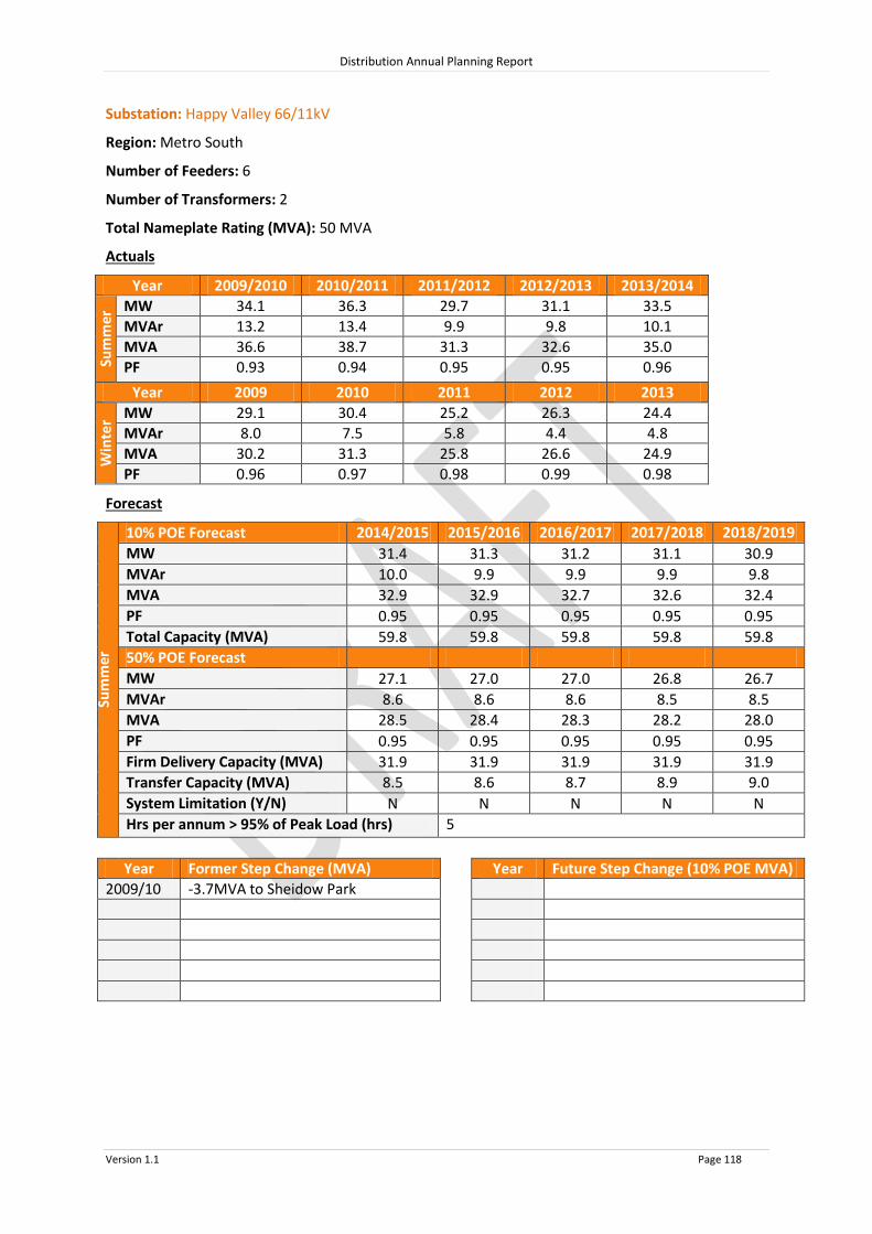
Distribution Annual Planning Report
Version 1.1 Page 118
Substation: Happy Valley 66/11kV
Region: Metro South
Number of Feeders: 6
Number of Transformers: 2
Total Nameplate Rating (MVA): 50 MVA
Actuals
Year 2009/2010 2010/2011 2011/2012 2012/2013 2013/2014
Sum
mer
MW 34.1 36.3 29.7 31.1 33.5
MVAr 13.2 13.4 9.9 9.8 10.1
MVA 36.6 38.7 31.3 32.6 35.0
PF 0.93 0.94 0.95 0.95 0.96
Year 2009 2010 2011 2012 2013
Win
ter MW 29.1 30.4 25.2 26.3 24.4
MVAr 8.0 7.5 5.8 4.4 4.8
MVA 30.2 31.3 25.8 26.6 24.9
PF 0.96 0.97 0.98 0.99 0.98
Forecast
Sum
mer
10% POE Forecast 2014/2015 2015/2016 2016/2017 2017/2018 2018/2019
MW 31.4 31.3 31.2 31.1 30.9
MVAr 10.0 9.9 9.9 9.9 9.8
MVA 32.9 32.9 32.7 32.6 32.4
PF 0.95 0.95 0.95 0.95 0.95
Total Capacity (MVA) 59.8 59.8 59.8 59.8 59.8
50% POE Forecast
MW 27.1 27.0 27.0 26.8 26.7
MVAr 8.6 8.6 8.6 8.5 8.5
MVA 28.5
28.4
28.3
28.2
28.0 PF 0.95 0.95 0.95 0.95 0.95
Firm Delivery Capacity (MVA) 31.9 31.9 31.9 31.9 31.9
Transfer Capacity (MVA) 8.5
8.6
8.7
8.9
9.0 System Limitation (Y/N) N N N N N
Hrs per annum > 95% of Peak Load (hrs) 5
Year Former Step Change (MVA) Year Future Step Change (10% POE MVA)
2009/10 -3.7MVA to Sheidow Park

Distribution Annual Planning Report
Version 1.1 Page 119
Substation: Keswick 66/11kV
Region: Metro South
Number of Feeders: 8
Number of Transformers: 2
Total Nameplate Rating (MVA): 42 MVA
Actuals
Year 2009/2010 2010/2011 2011/2012 2012/2013 2013/2014
Sum
mer
MW 37.1 41.5 38.1 38.5 37.3
MVAr 5.3 6.5 11.7 11.1 10.4
MVA 37.5 42.0 39.9 40.0 38.7
PF 0.99 0.99 0.96 0.96 0.96
Year 2009 2010 2011 2012 2013
Win
ter MW 27.5 27.3 28.4 31.0 29.1
MVAr 13.0 12.4 12.2 12.8 11.4
MVA 30.4 30.0 30.9 33.6 31.3
PF 0.90 0.91 0.92 0.92 0.93
Forecast
Sum
mer
10% POE Forecast 2014/2015 2015/2016 2016/2017 2017/2018 2018/2019
MW 36.3 36.4 36.5 36.5 36.5
MVAr 10.6 10.6 10.6 10.6 10.6
MVA 37.9 37.9 38 38 38
PF 0.96 0.96 0.96 0.96 0.96
Total Capacity (MVA) 49.1 49.1 49.1 49.1 49.1
50% POE Forecast
MW 33.2 33.2 33.1 33.0 32.9
MVAr 9.7 9.7 9.6 9.6 9.6
MVA 34.6 34.5 34.5 34.4 34.3
PF 0.96 0.96 0.96 0.96 0.96
Firm Delivery Capacity (MVA) 25.8 25.8 25.8 25.8 25.8
Transfer Capacity (MVA) 23.2 23.5 23.8 24.1 24.4
System Limitation (Y/N) N N N N N
Hrs per annum > 95% of Peak Load (hrs) 9
Year Former Step Change (MVA) Year Future Step Change (10% POE MVA)
2010/11 +1.0MVA Customer load increase
2010/11 +2.3MVA from Plympton
+0.5MVA from New Richmond
2012/13 -2.2MVA to Clarence Gardens

Distribution Annual Planning Report
Version 1.1 Page 120
Substation: Kingswood 66/11kV
Region: Metro South
Number of Feeders: 8
Number of Transformers: 2
Total Nameplate Rating (MVA): 64 MVA
Actuals
Year 2009/2010 2010/2011 2011/2012 2012/2013 2013/2014
Sum
mer
MW 54.6 56.0 44.7 46.7 46.6
MVAr 23.5 22.4 17.6 18.4 17.0
MVA 59.5 60.3 48.1 50.2 49.6
PF 0.92 0.93 0.93 0.93 0.94
Year 2009 2010 2011 2012 2013
Win
ter MW 39.0 41.5 37.1 34.7 34.0
MVAr 12.4 12.9 10.1 9.2 8.8
MVA 40.9 43.5 38.4 35.9 35.1
PF 0.95 0.96 0.97 0.97 0.97
Forecast
Sum
mer
10% POE Forecast 2014/2015 2015/2016 2016/2017 2017/2018 2018/2019
MW 44.4 44.7 44.9 45.1 45.2
MVAr 17.0 17.1 17.2 17.3 17.3
MVA 47.6 47.9 48.1 48.3 48.4
PF 0.93 0.93 0.93 0.93 0.93
Total Capacity (MVA) 71.2 71.2 71.2 71.2 71.2
50% POE Forecast
MW 38.7 38.9 39.2 39.4 39.6
MVAr 14.8 14.9 15.0 15.1 15.2
MVA 41.4
41.7
42.0
42.2
42.4 PF 0.93 0.93 0.93 0.93 0.93
Firm Delivery Capacity (MVA) 37.5 37.5 37.5 37.5 37.5
Transfer Capacity (MVA) 18.5
18.6
18.7
18.8
18.9 System Limitation (Y/N) N N N N N
Hrs per annum > 95% of Peak Load (hrs) 6
Year Former Step Change (MVA) Year Future Step Change (10% POE MVA)
2009/10 -2.2MVA to Lower Mitcham
2010/11 +1.5MVA from North Unley
-2.0 MVA to Lower Mitcham
2011/12 -2.9MVA to Linden Park
2012/13 -3.8MVA to Clarence Gardens

Distribution Annual Planning Report
Version 1.1 Page 121
Substation: Lower Mitcham 66/11kV
Region: Metro South
Number of Feeders: 4
Number of Transformers: 2
Total Nameplate Rating (MVA): 20 MVA
Actuals
Year 2009/2010 2010/2011 2011/2012 2012/2013 2013/2014
Sum
mer
MW 17.6 21.0 17.7 18.3 19.2
MVAr 6.8 7.5 6.2 6.1 5.4
MVA 18.9 22.3 18.7 19.3 20.0
PF 0.93 0.94 0.94 0.95 0.96
Year 2009 2010 2011 2012 2013
Win
ter MW 11.9 14.8 14.9 14.0 14.3
MVAr 3.4 4.3 3.9 3.4 3.2
MVA 12.3 15.4 15.4 14.4 14.6
PF 0.96 0.96 0.97 0.97 0.98
Forecast
Sum
mer
10% POE Forecast 2014/2015 2015/2016 2016/2017 2017/2018 2018/2019
MW 18.2 18.3 18.3 18.4 18.4
MVAr 5.9 5.9 5.9 5.9 5.9
MVA 19.2 19.2 19.3 19.3 19.3
PF 0.95 0.95 0.95 0.95 0.95
Total Capacity (MVA) 28.2 28.2 28.2 28.2 28.2
50% POE Forecast
MW 15.7 15.7 15.6 15.5 15.4
MVAr 5.1 5.0 5.0 5.0 4.9
MVA 16.5
16.5
16.4
16.3
16.2 PF 0.95 0.95 0.95 0.95 0.95
Firm Delivery Capacity (MVA) 15.0 15.0 15.0 15.0 15.0
Transfer Capacity (MVA) 8.2
8.3
8.5
8.6
8.7 System Limitation (Y/N) N N N N N
Hrs per annum > 95% of Peak Load (hrs) 7
Year Former Step Change (MVA) Year Future Step Change (10% POE MVA)
2009/10 +2.2MVA from Kingswood
2010/11 +2.0MVA from Kingswood
2012/13 +2.5MVA Customer load increase

Distribution Annual Planning Report
Version 1.1 Page 122
Substation: McLaren Flat 66/11kV
Region: Metro South
Number of Feeders: 3
Number of Transformers: 2
Total Nameplate Rating (MVA): 25 MVA
Actuals
Year 2009/2010 2010/2011 2011/2012 2012/2013 2013/2014
Sum
mer
MW 6.0 10.0 10.0 10.0 9.7
MVAr 3.6 3.2 5.0 5.0 4.3
MVA 7.0 10.5 11.2 11.2 10.6
PF 0.86 0.95 0.89 0.89 0.92
Year 2009 2010 2011 2012 2013
Win
ter MW 4.0 8.0 8.0 6.0 7.0
MVAr 1.0 2.0 2.0 2.0 2.0
MVA 4.1 8.2 8.2 6.3 7.3
PF 0.97 0.97 0.97 0.95 0.96
Forecast
Sum
mer
10% POE Forecast 2014/2015 2015/2016 2016/2017 2017/2018 2018/2019
MW 9.4 9.6 9.7 9.8 9.9
MVAr 4.3 4.3 4.4 4.4 4.5
MVA 10.3 10.5 10.6 10.7 10.9
PF 0.91 0.91 0.91 0.91 0.91
Total Capacity (MVA) 31.0 31.0 31.0 31.0 31.0
50% POE Forecast
MW 8.2 8.2 8.2 8.2 8.2
MVAr 3.7 3.7 3.7 3.7 3.7
MVA 9.0
9.0
9.0
9.0
9.0 PF 0.91 0.91 0.91 0.91 0.91
Firm Delivery Capacity (MVA) 16.8 16.8 16.8 16.8 16.8
Transfer Capacity (MVA) 4.3
4.4
4.4
4.5
4.5 System Limitation (Y/N) N N N N N
Hrs per annum > 95% of Peak Load (hrs) 9
Year Former Step Change (MVA) Year Future Step Change (10% POE MVA)
2010/11 +4.5MVA from McLaren Vale
2011/12 +1.3MVA from McLaren Vale
+0.4MVA from Clarendon
2012/13 +0.4MVA Customer load increase
-2.6MVA to Port Noarlunga

Distribution Annual Planning Report
Version 1.1 Page 123
Substation: McLaren Vale 33/11kV
Region: Metro South
Number of Feeders: 1
Number of Transformers: 2
Total Nameplate Rating (MVA): 5 MVA
Actuals
Year 2009/2010 2010/2011 2011/2012 2012/2013 2013/2014
Sum
mer
MW 5.8 N/A 1.7 2.3 2.3
MVAr 3.0 N/A 0.4 0.5 1.0
MVA 6.6 N/A 1.8 2.4 2.5
PF 0.89 N/A 0.97 0.98 0.92
Year 2009 2010 2011 2012 2013
Win
ter MW 4.0 2.0 1.8 1.9 2.0
MVAr 1.4 0.3 0.3 0.2 1.1
MVA 4.2 2.0 1.8 1.9 2.3
PF 0.94 0.99 0.99 1.00 0.87
Forecast
Sum
mer
10% POE Forecast 2014/2015 2015/2016 2016/2017 2017/2018 2018/2019
MW 2.2 2.2 2.3 2.3 2.4
MVAr 1.0 1.0 1.1 1.1 1.1
MVA 2.4 2.5 2.5 2.6 2.6
PF 0.91 0.91 0.91 0.91 0.91
Total Capacity (MVA) 5.4 5.4 5.4 5.4 5.4
50% POE Forecast
MW 1.9 1.9 2.0 2.0 2.1
MVAr 0.9 0.9 0.9 0.9 1.0
MVA 2.1
2.1
2.2
2.3
2.3 PF 0.91 0.91 0.91 0.91 0.91
Firm Delivery Capacity (MVA) 3.0 3.0 3.0 3.0 3.0
Transfer Capacity (MVA) 3.0
2.9
2.8
2.8
2.7 System Limitation (Y/N) N N N N N
Hrs per annum > 95% of Peak Load (hrs) 7
Year Former Step Change (MVA) Year Future Step Change (10% POE MVA)
2009/10 +0.5MVA from Port Noarlunga
2010/11 -4.5MVA to McLaren Flat
2011/12 -1.3MVA to McLaren Flat

Distribution Annual Planning Report
Version 1.1 Page 124
Substation: Morphett Vale East 66/11kV
Region: Metro South
Number of Feeders: 6
Number of Transformers: 2
Total Nameplate Rating (MVA): 48 MVA
Actuals
Year 2009/2010 2010/2011 2011/2012 2012/2013 2013/2014
Sum
mer
MW 41.6 36.5 30.8 28.0 33.5
MVAr 14.2 12.2 10.9 8.6 10.2
MVA 44.0 38.5 32.7 29.3 35.0
PF 0.95 0.95 0.94 0.96 0.96
Year 2009 2010 2011 2012 2013
Win
ter MW 30.9 32.3 29.5 24.8 23.2
MVAr 6.5 7.6 6.4 5.2 3.8
MVA 31.6 33.2 30.2 25.3 23.5
PF 0.98 0.97 0.98 0.98 0.99
Forecast
Sum
mer
10% POE Forecast 2014/2015 2015/2016 2016/2017 2017/2018 2018/2019
MW 30.9 30.4 30.0 29.5 29.0
MVAr 9.9 9.7 9.6 9.4 9.3
MVA 32.4 32.0 31.5 30.9 30.4
PF 0.95 0.95 0.95 0.95 0.95
Total Capacity (MVA) 57.3 57.3 57.3 57.3 57.3
50% POE Forecast
MW 27.0 26.7 26.4 26.1 25.7
MVAr 8.6 8.5 8.4 8.3 8.2
MVA 28.4
28.0
27.7
27.4
27.0 PF 0.95 0.95 0.95 0.95 0.95
Firm Delivery Capacity (MVA) 30.5 30.5 30.5 30.5 30.5
Transfer Capacity (MVA) 23.3
23.8
24.3
24.8
25.4 System Limitation (Y/N) N N N N N
Hrs per annum > 95% of Peak Load (hrs) 6
Year Former Step Change (MVA) Year Future Step Change (10% POE MVA)
2009/10 +0.7MVA from Port Noarlunga
2010/11 -6.8MVA to Hackham

Distribution Annual Planning Report
Version 1.1 Page 125
Substation: Morphettville 66/11kV
Region: Metro South
Number of Feeders: 4
Number of Transformers: 2
Total Nameplate Rating (MVA): 20 MVA
Actuals
Year 2009/2010 2010/2011 2011/2012 2012/2013 2013/2014
Sum
mer
MW 23.9 25.4 21.2 21.1 24.6
MVAr 6.6 7.2 4.2 3.9 5.5
MVA 24.8 26.4 21.6 21.4 25.2
PF 0.96 0.96 0.98 0.98 0.98
Year 2009 2010 2011 2012 2013
Win
ter MW 17.1 18.3 17.3 17.0 16.0
MVAr 7.2 7.3 6.8 6.0 5.6
MVA 18.5 19.7 18.6 18.0 17.0
PF 0.92 0.93 0.93 0.94 0.94
Forecast
Sum
mer
10% POE Forecast 2014/2015 2015/2016 2016/2017 2017/2018 2018/2019
MW 22.2 22.5 22.7 22.8 23.0
MVAr 4.0 4.0 4.1 4.1 4.1
MVA 22.6 22.8 23 23.2 23.4
PF 0.98 0.98 0.98 0.98 0.98
Total Capacity (MVA) 28.0 28.0 28.0 28.0 28.0
50% POE Forecast
MW 19.6 19.8 19.9 20.1 20.2
MVAr 3.5 3.6 3.6 3.6 3.6
MVA 19.9 20.1 20.3 20.4 20.5
PF 0.98 0.98 0.98 0.98 0.98
Firm Delivery Capacity (MVA) 15.0 15.0 15.0 15.0 15.0
Transfer Capacity (MVA) 13.0
13.1
13.1
13.2
13.3 System Limitation (Y/N) N N N N N
Hrs per annum > 95% of Peak Load (hrs) 7
Year Former Step Change (MVA) Year Future Step Change (10% POE MVA)
2011/12 -1.2MVA to Oaklands
-3.4MVA to Ascot Park
+3.6MVA from Glenelg North

Distribution Annual Planning Report
Version 1.1 Page 126
Substation: Noarlunga Centre 66/11kV
Region: Metro South
Number of Feeders: 5
Number of Transformers: 2
Total Nameplate Rating (MVA): 20 MVA
Actuals
Year 2009/2010 2010/2011 2011/2012 2012/2013 2013/2014
Sum
mer
MW 24.2 20.3 17.1 19.2 18.7
MVAr 9.6 8.2 7.3 7.7 7.8
MVA 26.1 21.9 18.6 20.7 20.3
PF 0.93 0.93 0.92 0.93 0.92
Year 2009 2010 2011 2012 2013
Win
ter MW 15.3 15.7 15.8 12.5 13.3
MVAr 4.7 4.3 5.8 4.3 4.0
MVA 16.0 16.3 16.9 13.2 13.9
PF 0.96 0.96 0.94 0.95 0.96
Forecast
Sum
mer
10% POE Forecast 2014/2015 2015/2016 2016/2017 2017/2018 2018/2019
MW 16.6 16.4 16.1 15.8 15.6
MVAr 6.9 6.8 6.7 6.6 6.5
MVA 18.0 17.7 17.4 17.1 16.9
PF 0.92 0.92 0.92 0.92 0.92
Total Capacity (MVA) 28.3 28.3 28.3 28.3 28.3
50% POE Forecast
MW 15.2 15.1 15.0 14.9 14.7
MVAr 6.3 6.3 6.2 6.2 6.1
MVA 16.5
16.4
16.2
16.1
16.0 PF 0.92 0.92 0.92 0.92 0.92
Firm Delivery Capacity (MVA) 15.0 15.0 15.0 15.0 15.0
Transfer Capacity (MVA) 21.3
21.7
22.1
22.5
22.9 System Limitation (Y/N) N N N N N
Hrs per annum > 95% of Peak Load (hrs) 9
Year Former Step Change (MVA) Year Future Step Change (10% POE MVA)
2010/11 -1.6MVA to Hackham

Distribution Annual Planning Report
Version 1.1 Page 127
Substation: North Unley 66/11kV
Region: Metro South
Number of Feeders: 4
Number of Transformers: 2
Total Nameplate Rating (MVA): 20 MVA
Actuals
Year 2009/2010 2010/2011 2011/2012 2012/2013 2013/2014
Sum
mer
MW 21.6 20.5 17.4 17.6 18.4
MVAr 10.2 9.7 8.0 7.8 7.8
MVA 23.9 22.7 19.2 19.2 20.0
PF 0.91 0.90 0.91 0.91 0.92
Year 2009 2010 2011 2012 2013
Win
ter MW 13.6 13.3 12.4 12.0 11.4
MVAr 5.9 5.1 4.9 3.5 3.9
MVA 14.8 14.2 13.4 12.5 12.0
PF 0.92 0.93 0.93 0.96 0.95
Forecast
Sum
mer
10% POE Forecast 2014/2015 2015/2016 2016/2017 2017/2018 2018/2019
MW 17.1 16.9 16.8 16.6 16.4
MVAr 7.5 7.4 7.4 7.3 7.2
MVA 18.7 18.5 18.3 18.1 17.9
PF 0.92 0.92 0.92 0.92 0.92
Total Capacity (MVA) 25.4 25.4 25.4 25.4 25.4
50% POE Forecast
MW 15.2 15.0 14.9 14.7 14.5
MVAr 6.7 6.6 6.5 6.5 6.4
MVA 16.6
16.4
16.3
16.1
15.9 PF 0.92 0.92 0.92 0.92 0.92
Firm Delivery Capacity (MVA) 13.5 13.5 13.5 13.5 13.5
Transfer Capacity (MVA) 5.7
5.8
5.9
6.0
6.1 System Limitation (Y/N) N N N N N
Hrs per annum > 95% of Peak Load (hrs) 9
Year Former Step Change (MVA) Year Future Step Change (10% POE MVA)
2010/11 -1.5MVA to Kingswood

Distribution Annual Planning Report
Version 1.1 Page 128
Substation: Oaklands 66/11kV
Region: Metro South
Number of Feeders: 7
Number of Transformers: 2
Total Nameplate Rating (MVA): 48 MVA
Actuals
Year 2009/2010 2010/2011 2011/2012 2012/2013 2013/2014
Sum
mer
MW 43.5 44.3 37.9 40.4 46.0
MVAr 12.7 11.2 8.0 9.0 10.1
MVA 45.3 45.7 38.7 41.4 47.1
PF 0.96 0.97 0.98 0.98 0.98
Year 2009 2010 2011 2012 2013
Win
ter MW 29.7 31.5 30.2 31.4 29.1
MVAr 2.9 3.3 2.8 0.0 1.6
MVA 29.8 31.6 30.3 31.4 29.2
PF 1.00 1.00 1.00 1.00 1.00
Forecast
Sum
mer
10% POE Forecast 2014/2015 2015/2016 2016/2017 2017/2018 2018/2019
MW 41.6 41.7 41.7 41.7 41.7
MVAr 8.8 8.8 8.8 8.8 8.8
MVA 42.5 42.6 42.7 42.6 42.6
PF 0.98 0.98 0.98 0.98 0.98
Total Capacity (MVA) 57.5 57.5 57.5 57.5 57.5
50% POE Forecast
MW 36.7 36.6 36.6 36.5 36.4
MVAr 7.7 7.7 7.7 7.7 7.7
MVA 37.5 37.4 37.4 37.3 37.2
PF 0.98 0.98 0.98 0.98 0.98
Firm Delivery Capacity (MVA) 30.3 30.3 30.3 30.3 30.3
Transfer Capacity (MVA) 18.6
18.9
19.1
19.3
19.6 System Limitation (Y/N) N N N N N
Hrs per annum > 95% of Peak Load (hrs) 9
Year Former Step Change (MVA) Year Future Step Change (10% POE MVA)
2011/12 +1.2MVA from Morphettville

Distribution Annual Planning Report
Version 1.1 Page 129
Substation: Panorama 66/11kV
Region: Metro South
Number of Feeders: 6
Number of Transformers: 2
Total Nameplate Rating (MVA): 50 MVA
Actuals
Year 2009/2010 2010/2011 2011/2012 2012/2013 2013/2014
Sum
mer
MW 21.8 23.1 20.7 21.3 24.2
MVAr 3.0 3.0 1.4 6.8 6.7
MVA 22.0 23.3 20.7 22.4 25.1
PF 0.99 0.99 1.00 0.95 0.96
Year 2009 2010 2011 2012 2013
Win
ter MW 16.2 16.8 15.4 16.8 17.1
MVAr 4.8 5.2 4.2 4.0 3.5
MVA 16.9 17.6 16.0 17.2 17.5
PF 0.96 0.96 0.97 0.97 0.98
Forecast
Sum
mer
10% POE Forecast 2014/2015 2015/2016 2016/2017 2017/2018 2018/2019
MW 22.6 22.7 22.8 22.8 22.8
MVAr 5.5 5.6 5.6 5.6 5.6
MVA 23.3 23.4 23.4 23.5 23.5
PF 0.97 0.97 0.97 0.97 0.97
Total Capacity (MVA) 58.2 58.2 58.2 58.2 58.2
50% POE Forecast
MW 19.7 19.8 19.9 19.9 20.0
MVAr 4.8 4.9 4.9 4.9 4.9
MVA 20.3
20.4
20.5
20.5
20.6 PF 0.97 0.97 0.97 0.97 0.97
Firm Delivery Capacity (MVA) 30.7 30.7 30.7 30.7 30.7
Transfer Capacity (MVA) 14.6
14.7
14.9
15.0
15.2 System Limitation (Y/N) N N N N N
Hrs per annum > 95% of Peak Load (hrs) 7
Year Former Step Change (MVA) Year Future Step Change (10% POE MVA)
2011/12 -1.1MVA to Cudmore Park
2012/13 +3.5MVA Customer load increase

Distribution Annual Planning Report
Version 1.1 Page 130
Substation: Plympton 66/11kV
Region: Metro South
Number of Feeders: 6
Number of Transformers: 2
Total Nameplate Rating (MVA): 20 MVA
Actuals
Year 2009/2010 2010/2011 2011/2012 2012/2013 2013/2014
Sum
mer
MW 23.6 24.0 21.2 20.9 21.6
MVAr 3.2 4.4 2.3 2.3 1.5
MVA 23.8 24.4 21.4 21.1 21.7
PF 0.99 0.98 0.99 0.99 1.00
Year 2009 2010 2011 2012 2013
Win
ter MW 17.7 22.0 15.4 19.7 16.2
MVAr 5.8 6.6 4.2 5.9 4.3
MVA 18.6 23.0 16.0 20.6 16.8
PF 0.95 0.96 0.97 0.96 0.97
Forecast
Sum
mer
10% POE Forecast 2014/2015 2015/2016 2016/2017 2017/2018 2018/2019
MW 19.6 19.4 19.2 18.9 18.6
MVAr 1.9 1.9 1.9 1.8 1.8
MVA 19.7 19.5 19.3 19 18.7
PF 1.00 1.00 1.00 1.00 1.00
Total Capacity (MVA) 28.4 28.4 28.4 28.4 28.4
50% POE Forecast
MW 17.4 17.2 17.0 16.7 16.4
MVAr 1.7 1.7 1.7 1.6 1.6
MVA 17.5 17.3 17 16.8 16.5
PF 1.00 1.00 1.00 1.00 1.00
Firm Delivery Capacity (MVA) 15.0 15.0 15.0 15.0 15.0
Transfer Capacity (MVA) 17.1
17.5
17.9
18.4
18.8 System Limitation (Y/N) N N N N N
Hrs per annum > 95% of Peak Load (hrs) 7
Year Former Step Change (MVA) Year Future Step Change (10% POE MVA)
2009/10 +2.0MVA Customer load increase
2010/11 +3.0MVA from Glenelg North
-2.3MVA to Keswick
2012/13 -1.3MVA to Clarence Gardens
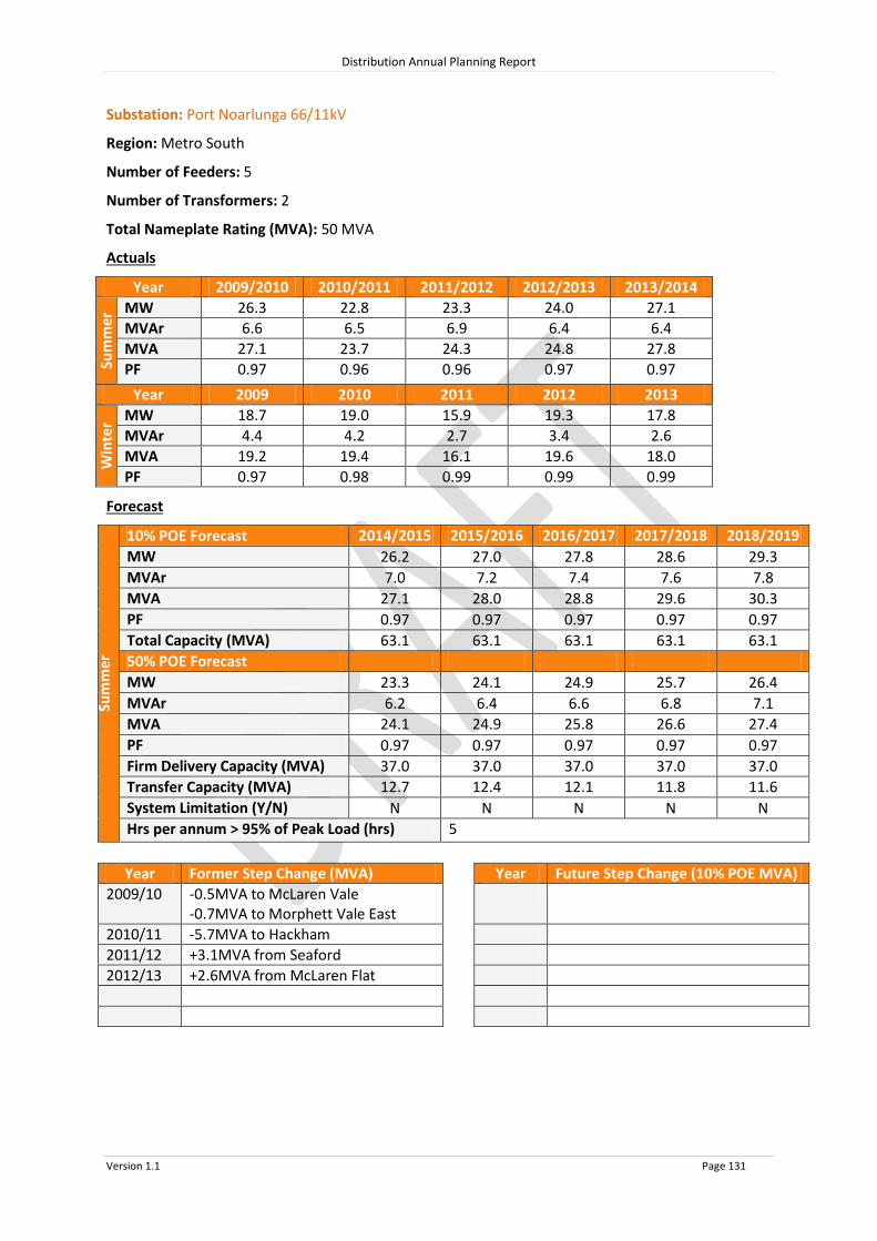
Distribution Annual Planning Report
Version 1.1 Page 131
Substation: Port Noarlunga 66/11kV
Region: Metro South
Number of Feeders: 5
Number of Transformers: 2
Total Nameplate Rating (MVA): 50 MVA
Actuals
Year 2009/2010 2010/2011 2011/2012 2012/2013 2013/2014
Sum
mer
MW 26.3 22.8 23.3 24.0 27.1
MVAr 6.6 6.5 6.9 6.4 6.4
MVA 27.1 23.7 24.3 24.8 27.8
PF 0.97 0.96 0.96 0.97 0.97
Year 2009 2010 2011 2012 2013
Win
ter MW 18.7 19.0 15.9 19.3 17.8
MVAr 4.4 4.2 2.7 3.4 2.6
MVA 19.2 19.4 16.1 19.6 18.0
PF 0.97 0.98 0.99 0.99 0.99
Forecast
Sum
mer
10% POE Forecast 2014/2015 2015/2016 2016/2017 2017/2018 2018/2019
MW 26.2 27.0 27.8 28.6 29.3
MVAr 7.0 7.2 7.4 7.6 7.8
MVA 27.1 28.0 28.8 29.6 30.3
PF 0.97 0.97 0.97 0.97 0.97
Total Capacity (MVA) 63.1 63.1 63.1 63.1 63.1
50% POE Forecast
MW 23.3 24.1 24.9 25.7 26.4
MVAr 6.2 6.4 6.6 6.8 7.1
MVA 24.1
24.9
25.8
26.6
27.4 PF 0.97 0.97 0.97 0.97 0.97
Firm Delivery Capacity (MVA) 37.0 37.0 37.0 37.0 37.0
Transfer Capacity (MVA) 12.7
12.4
12.1
11.8
11.6 System Limitation (Y/N) N N N N N
Hrs per annum > 95% of Peak Load (hrs) 5
Year Former Step Change (MVA) Year Future Step Change (10% POE MVA)
2009/10 -0.5MVA to McLaren Vale -0.7MVA to Morphett Vale East
2010/11 -5.7MVA to Hackham
2011/12 +3.1MVA from Seaford
2012/13 +2.6MVA from McLaren Flat

Distribution Annual Planning Report
Version 1.1 Page 132
Substation: Port Stanvac 66/11kV
Region: Metro South
Number of Feeders: 18
Number of Transformers: 3
Total Nameplate Rating (MVA): 75 MVA
Actuals
Year 2009/2010 2010/2011 2011/2012 2012/2013 2013/2014
Sum
mer
MW 37.6 38.6 34.6 35.9 37.0
MVAr 12.5 11.9 10.5 11.4 9.0
MVA 39.6 40.4 36.2 37.7 38.1
PF 0.95 0.96 0.96 0.95 0.97
Year 2009 2010 2011 2012 2013
Win
ter MW 28.2 33.6 29.0 28.4 30.9
MVAr 6.4 8.4 6.0 4.5 5.6
MVA 28.9 34.7 29.6 28.8 31.4
PF 0.98 0.97 0.98 0.99 0.98
Forecast
Sum
mer
10% POE Forecast 2014/2015 2015/2016 2016/2017 2017/2018 2018/2019
MW 35.1 34.8 34.5 34.2 33.8
MVAr 10.2 10.2 10.1 10.0 9.9
MVA 36.5 36.2 36 35.6 35.2
PF 0.96 0.96 0.96 0.96 0.96
Total Capacity (MVA) 88.6 88.6 88.6 88.6 88.6
50% POE Forecast
MW 31.8 31.4 31.0 30.5 30.1
MVAr 9.3 9.2 9.1 8.9 8.8
MVA 33.2 32.7 32.3 31.8 31.3
PF 0.96 0.96 0.96 0.96 0.96
Firm Delivery Capacity (MVA) 62.0 62.0 62.0 62.0 62.0
Transfer Capacity (MVA) 19.9
20.4
20.8
21.3
21.8 System Limitation (Y/N) N N N N N
Hrs per annum > 95% of Peak Load (hrs) 9
Year Former Step Change (MVA) Year Future Step Change (10% POE MVA)
2009/10 +5.2MVA from Sheidow Park
+2.1MVA Customer load increase
2011/12 -4.0MVA Customer load decrease
*Impact of below embedded generation removed from Actuals & excluded from Forecast:
21MW of Diesel export generation at 11kV

Distribution Annual Planning Report
Version 1.1 Page 133
Substation: Seacombe 66/11kV
Region: Metro South
Number of Feeders: 8
Number of Transformers: 2
Total Nameplate Rating (MVA): 50 MVA
Actuals
Year 2009/2010 2010/2011 2011/2012 2012/2013 2013/2014
Sum
mer
MW 37.6 39.0 36.1 37.0 42.2
MVAr 8.2 6.3 5.2 4.6 5.7
MVA 38.5 39.5 36.5 37.3 42.6
PF 0.98 0.99 0.99 0.99 0.99
Year 2009 2010 2011 2012 2013
Win
ter MW 25.9 28.2 27.5 30.1 29.6
MVAr 1.0 1.1 5.9 0.0 5.5
MVA 25.9 28.3 28.1 30.1 30.1
PF 1.00 1.00 0.98 1.00 0.98
Forecast
Sum
mer
10% POE Forecast 2014/2015 2015/2016 2016/2017 2017/2018 2018/2019
MW 39.7 40.1 40.5 40.8 41.1
MVAr 5.4 5.4 5.5 5.5 5.6
MVA 40 40.4 40.8 41.1 41.5
PF 0.99 0.99 0.99 0.99 0.99
Total Capacity (MVA) 59.2 59.2 59.2 59.2 59.2
50% POE Forecast
MW 35.0 35.2 35.4 35.5 35.7
MVAr 4.8 4.8 4.8 4.8 4.8
MVA 35.3 35.5 35.7 35.9 36
PF 0.99 0.99 0.99 0.99 0.99
Firm Delivery Capacity (MVA) 31.6 31.6 31.6 31.6 31.6
Transfer Capacity (MVA) 14.7
14.8
14.9
15.0
15.1 System Limitation (Y/N) N N N N N
Hrs per annum > 95% of Peak Load (hrs) 7
Year Former Step Change (MVA) Year Future Step Change (10% POE MVA)
2009/10 +0.7MVA from Sheidow Park
2010/11 -2.0MVA to Tonsley Park
2011/12 +3.8MVA from Sheidow Park

Distribution Annual Planning Report
Version 1.1 Page 134
Substation: Seaford 66/11kV
Region: Metro South
Number of Feeders: 2
Number of Transformers: 1
Total Nameplate Rating (MVA): 12.5 MVA
Actuals
Year 2009/2010 2010/2011 2011/2012 2012/2013 2013/2014
Sum
mer
MW 11.3 11.1 7.8 7.4 7.0
MVAr 4.5 4.6 2.8 2.2 2.5
MVA 12.2 12.0 8.3 7.8 7.4
PF 0.93 0.93 0.94 0.96 0.94
Year 2009 2010 2011 2012 2013
Win
ter MW 7.6 8.8 6.6 6.6 5.4
MVAr 1.7 1.8 1.6 1.3 0.8
MVA 7.8 9.0 6.8 6.7 5.4
PF 0.98 0.98 0.97 0.98 0.99
Forecast
Sum
mer
10% POE Forecast 2014/2015 2015/2016 2016/2017 2017/2018 2018/2019
MW 6.3 6.4 6.6 6.6 6.7
MVAr 2.8 2.8 2.9 2.9 2.9
MVA 6.9 7.0 7.2 7.3 7.4
PF 0.92 0.92 0.92 0.92 0.92
Total Capacity (MVA) 15.8 15.8 15.8 15.8 15.8
50% POE Forecast
MW 5.4 5.6 5.9 6.1 6.3
MVAr 2.4 2.5 2.6 2.7 2.8
MVA 5.9
6.2
6.4
6.7
6.9 PF 0.92 0.92 0.92 0.92 0.92
Firm Delivery Capacity (MVA) 0.0 0.0 0.0 0.0 0.0
Transfer Capacity (MVA) 10.9
10.6
10.2
10.0
9.7 System Limitation (Y/N) N N N N N
Hrs per annum > 95% of Peak Load (hrs) 7
Year Former Step Change (MVA) Year Future Step Change (10% POE MVA)
2009/10 +1.0MVA from Aldinga
2010/11 -1.0MVA to Aldinga
2011/12 -3.1MVA to Port Noarlunga

Distribution Annual Planning Report
Version 1.1 Page 135
Substation: Sheidow Park 66/11kV
Region: Metro South
Number of Feeders: 5
Number of Transformers: 2
Total Nameplate Rating (MVA): 25 MVA
Actuals
Year 2009/2010 2010/2011 2011/2012 2012/2013 2013/2014
Sum
mer
MW 29.1 28.4 20.8 22.1 24.9
MVAr 10.4 10.0 3.8 0.7 0.0
MVA 30.9 30.1 21.2 22.2 24.9
PF 0.94 0.94 0.98 1.00 1.00
Year 2009 2010 2011 2012 2013
Win
ter MW 22.7 14.9 19.0 17.9 16.7
MVAr 5.0 2.7 3.7 0.6 2.4
MVA 23.2 15.1 19.3 17.9 16.9
PF 0.98 0.98 0.98 1.00 0.99
Forecast
Sum
mer
10% POE Forecast 2014/2015 2015/2016 2016/2017 2017/2018 2018/2019
MW 22.6 22.6 22.6 22.6 22.6
MVAr 2.4 2.4 2.4 2.4 2.4
MVA 22.7 22.7 22.7 22.7 22.7
PF 0.99 0.99 0.99 0.99 0.99
Total Capacity (MVA) 35.0 35.0 35.0 35.0 35.0
50% POE Forecast
MW 19.8 19.9 20.1 20.2 20.4
MVAr 2.1 2.1 2.2 2.2 2.2
MVA 19.9
20.1
20.2
20.4
20.5 PF 0.99 0.99 0.99 0.99 0.99
Firm Delivery Capacity (MVA) 18.6 18.6 18.6 18.6 18.6
Transfer Capacity (MVA) 10.5
10.5
10.5
10.5
10.6 System Limitation (Y/N) N N N N N
Hrs per annum > 95% of Peak Load (hrs) 5
Year Former Step Change (MVA) Year Future Step Change (10% POE MVA)
2009/10 +3.7MVA from Happy Valley
-5.2MVA to Port Stanvac
-0.7MVA to Seacombe
2011/12 -1.5MVA Installed 6MVAr Cap Bank
-3.8MVA to Seacombe

Distribution Annual Planning Report
Version 1.1 Page 136
Substation: Tonsley Park 66/11kV
Region: Metro South
Number of Feeders: 6
Number of Transformers: 3
Total Nameplate Rating (MVA): 30 MVA
Actuals
Year 2009/2010 2010/2011 2011/2012 2012/2013 2013/2014
Sum
mer
MW 27.8 19.7 19.4 20.5 20.5
MVAr 16.0 9.3 7.9 8.4 8.2
MVA 32.1 21.8 20.9 22.2 22.1
PF 0.87 0.90 0.93 0.93 0.93
Year 2009 2010 2011 2012 2013
Win
ter MW 13.5 14.6 12.5 15.1 14.7
MVAr 5.7 5.0 4.7 4.0 2.5
MVA 14.7 15.4 13.4 15.6 14.9
PF 0.92 0.95 0.94 0.97 0.99
Forecast
Sum
mer
10% POE Forecast 2014/2015 2015/2016 2016/2017 2017/2018 2018/2019
MW 19.6 19.5 19.4 19.2 19.1
MVAr 7.9 7.9 7.9 7.8 7.8
MVA 21.1 21.0 20.9 20.8 20.6
PF 0.93 0.93 0.93 0.93 0.93
Total Capacity (MVA) 40.1 40.1 40.1 40.1 40.1
50% POE Forecast
MW 17.4 17.2 17.0 16.9 16.7
MVAr 7.1 7.0 6.9 6.8 6.8
MVA 18.8
18.6
18.4
18.2
18.0 PF 0.93 0.93 0.93 0.93 0.93
Firm Delivery Capacity (MVA) 28.9 28.9 28.9 28.9 28.9
Transfer Capacity (MVA) 9.2
9.4
9.6
9.8
10.0 System Limitation (Y/N) N N N N N
Hrs per annum > 95% of Peak Load (hrs) 9
Year Former Step Change (MVA) Year Future Step Change (10% POE MVA)
2010/11 +2.0MVA from Seacombe
2011/12 +3.8MVA from Ascot Park
*Forecast excludes additional 11MVA of load reserved for the redevelopment of the former Mitsubishi site at Clovelly Park.

Distribution Annual Planning Report
Version 1.1 Page 137
Substation: Willunga 66/11kV
Region: Metro South
Number of Feeders: 3
Number of Transformers: 1
Total Nameplate Rating (MVA): 5 MVA
Actuals
Year 2009/2010 2010/2011 2011/2012 2012/2013 2013/2014
Sum
mer
MW 5.2 4.3 3.9 4.1 4.7
MVAr 2.6 1.6 1.6 1.8 1.9
MVA 5.8 4.6 4.3 4.5 5.1
PF 0.90 0.94 0.93 0.92 0.93
Year 2009 2010 2011 2012 2013
Win
ter MW 3.4 3.9 3.5 3.7 3.7
MVAr 0.0 0.6 0.6 0.5 0.5
MVA 3.4 4.0 3.6 3.7 3.7
PF 1.00 0.99 0.99 0.99 0.99
Forecast
Sum
mer
10% POE Forecast 2014/2015 2015/2016 2016/2017 2017/2018 2018/2019
MW 4.0 3.9 3.9 3.8 3.8
MVAr 1.7 1.6 1.6 1.6 1.6
MVA 4.3 4.3 4.2 4.2 4.1
PF 0.92 0.92 0.92 0.92 0.92
Total Capacity (MVA) 6.7 6.7 6.7 6.7 6.7
50% POE Forecast
MW 3.5 3.4 3.4 3.3 3.3
MVAr 1.5 1.4 1.4 1.4 1.4
MVA 3.8
3.7
3.7
3.6
3.6 PF 0.92 0.92 0.92 0.92 0.92
Firm Delivery Capacity (MVA) 0.0 0.0 0.0 0.0 0.0
Transfer Capacity (MVA) 0.9
0.9
0.9 0.9 0.9
System Limitation (Y/N) Y* Y* Y* Y* Y*
Hrs per annum > 95% of Peak Load (hrs) 5
Year Former Step Change (MVA) Year Future Step Change (10% POE MVA)

Distribution Annual Planning Report
Version 1.1 Page 138
Substation: Willunga 66/33kV
Region: Metro South
Number of Feeders: 1
Number of Transformers: 1
Total Nameplate Rating (MVA): 7.5 MVA
Actuals
Year 2009/2010 2010/2011 2011/2012 2012/2013 2013/2014
Sum
mer
MW 6.6 2.8 2.0 2.4 2.8
MVAr 3.4 1.1 0.7 0.9 0.9
MVA 7.4 3.0 2.2 2.6 2.9
PF 0.89 0.93 0.95 0.94 0.95
Year 2009 2010 2011 2012 2013
Win
ter MW 4.2 2.2 2.3 1.9 2.2
MVAr 1.7 0.3 0.4 0.4 0.3
MVA 4.6 2.2 2.3 2.0 2.2
PF 0.93 0.99 0.99 0.98 0.99
Forecast
Sum
mer
10% POE Forecast 2014/2015 2015/2016 2016/2017 2017/2018 2018/2019
MW 2.6 2.6 2.7 2.7 2.8
MVAr 0.8 0.9 0.9 0.9 0.9
MVA 2.7 2.8 2.8 2.9 2.9
PF 0.95 0.95 0.95 0.95 0.95
Total Capacity (MVA) 10.6 10.6 10.6 10.6 10.6
50% POE Forecast
MW 2.2 2.3 2.3 2.4 2.4
MVAr 0.7 0.7 0.8 0.8 0.8
MVA 2.3
2.4
2.5
2.5
2.6 PF 0.95 0.95 0.95 0.95 0.95
Firm Delivery Capacity (MVA) 0.0 0.0 0.0 0.0 0.0
Transfer Capacity (MVA) 3.0
2.9
2.9
2.8
2.8 System Limitation (Y/N) N N N N N
Hrs per annum > 95% of Peak Load (hrs) 5
Year Former Step Change (MVA) Year Future Step Change (10% POE MVA)
2009/10 +0.5MVA from Port Noarlunga
2010/11 -4.5MVA to McLaren Flat
2011/12 -1.3MVA to McLaren Flat
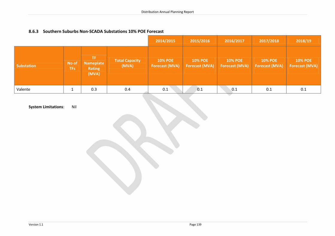
Distribution Annual Planning Report
Version 1.1 Page 139
8.6.3 Southern Suburbs Non-SCADA Substations 10% POE Forecast
2014/2015 2015/2
016 2016/2017
2017/2018
2014/2015 2015/2016 2016/2017 2017/2018 2018/19
Substation No of
TFs
TF Nameplate
Rating (MVA)
Total Capacity (MVA)
10% POE Forecast (MVA)
10% POE Forecast (MVA)
10% POE Forecast (MVA)
10% POE Forecast (MVA)
10% POE Forecast (MVA)
Valente 1 0.3 0.4 0.1 0.1 0.1 0.1 0.1
System Limitations: Nil

Distribution Annual Planning Report
Version 1.1 Page 140
8.6.4 Southern Suburbs 33kV Sub-transmission Lines
Line Name - From
To Total
Capacity^ (MVA)
Forecast 2014/2015
MVA
Forecast 2015/2016
MVA
Forecast 2016/2017
MVA
Forecast 2017/2018
MVA
Forecast 2018/2019
MVA
33kV lines ex Willunga
Willunga McLaren Vale 10.5 3.4 3.5 3.6 3.6 3.7
System Limitations: Nil ^ The published rating is based on a thermal limit or a limit required to maintain adequate clearances and does not take into account voltage limitations on the network which may further reduce the published rating.

Distribution Annual Planning Report
Version 1.1 Page 141
8.7 Adelaide Central Region (Central Business District) Regional Development Plan
The ACR
The SA Power Networks’ ACR includes the area east of West Terrace, north of South Terrace, west of East Terrace, and south of the River Torrens and contains the Adelaide CBD. The ACR is meshed within the Eastern Suburbs sub-transmission network system, supplied via East Terrace and City West connection points, with other sub-transmission lines supplying the ACR emanating from Magill and Northfield Connection Points. SA Power Networks’ Distribution Network Electricity is supplied throughout the ACR via Zone Substations. These Zone Substations are operated at either 66,000 Volts stepped down to 11,000 Volts or 33,000 Volts. Customers are supplied from SA Power Networks’ distribution system via 33kV and 11kV feeders, which are connected to distribution substations. The ACR feeder system is characterised by cables installed within an extensive duct and manhole system. These feeders are extended and upgraded as required to meet customer demand and customer connection requests. Large customer projects may require a Zone Substation upgrade as well as feeder modifications, therefore SA Power Networks should be notified as early as possible during the planning stages of a project so that customer connection requirements can be met. There are no system limitations forecast for the primary distribution feeders under normal conditions in the Adelaide Central Region in the next two years.
8.7.1 ACR SCADA Substations
Source Connection Point Associated SCADA Substations
ACR Meshed 66kV Network:
City West – ACR
East Tce
Coromandel Place
East Tce 11kV
East Tce 33kV
Hindley Street 11kV
Hindley Street 33kV Whitmore Square

HINDLEY STREET
EAST TERRACE
WHITMORE SQUARE
COROMANDEL PLACE
CITY WEST
0.00 0.25 0.50 0.75 1.00
Kilometres
Legend275kV Transmission Line132kV Transmission Line66kV Sub Transmission Line33kV Sub Transmission Line
Substation
CBD - ADELAIDECENTRAL REGION
System Limitation.

Distribution Annual Planning Report
Version 1.1 Page 143
Substation: Adelaide Central Region 275/66kV
Region: ACR
(ETC) Transmission Category: 5
Number of Transformers: 2
Total Nameplate Rating (MVA): 525 MVA
Forecast
Sum
mer
10% POE Forecast 2014/2015 2015/2016 2016/2017 2017/2018 2018/2019
MW 205 202 199 196 193
MVAr 50 64 63 63 62
MVA 210 211 209 206 203
PF 0.97 0.95 0.95 0.95 0.95
Firm Delivery Capacity (MVA) 270 270 270 270 270
System Limitation (Y/N) N N N N N
Hrs per annum > 95% of Peak Load (hrs)Hrs per annum > 95% of Peak Load (hrs)
0.0
13

Distribution Annual Planning Report
Version 1.1 Page 144
Substation: Coromandel Place 66/11kV
Region: ACR
Number of Feeders: 27
Number of Transformers: 3
Total Nameplate Rating (MVA): 75 MVA
Actuals
Year 2009/2010 2010/2011 2011/2012 2012/2013 2013/2014
Sum
mer
MW 47.5 48.2 43.7 50.1 50.6
MVAr 19.3 18.7 17.0 18.1 17.6
MVA 51.3 51.7 46.9 53.2 53.6
PF 0.93 0.93 0.93 0.94 0.94
Year 2009 2010 2011 2012 2013
Win
ter MW 29.4 29.9 34.4 29.6 30.9
MVAr 11.5 9.7 12.5 9.2 9.5
MVA 31.5 31.5 36.6 31.0 32.3
PF 0.93 0.95 0.94 0.96 0.96
Forecast
Sum
mer
10% POE Forecast 2014/2015 2015/2016 2016/2017 2017/2018 2018/2019
MW 51.6 50.9 50.2 49.5 48.8
MVAr 18.9 18.7 18.4 18.2 17.9
MVA 54.9 54.2 53.5 52.7 52.0
PF 0.94 0.94 0.94 0.94 0.94
Firm Delivery Capacity (MVA) 74.0 74.0 74.0 74.0 74.0
System Limitation (Y/N) N N N N N
Hrs per annum > 95% of Peak Load (hrs)Hrs per annum > 95% of Peak Load (hrs)
0.0
13
Year Former Step Change (MVA) Year Future Step Change (10% POE MVA)
2009/10 +1.2MVA from Whitmore Square
+0.6MVA from East Tce 33kV
+0.4MVA from Hindley St 33kV
2010/11 +0.6MVA from East Tce 33kV
+0.4MVA from Hindley St 33kV
2011/12 +0.6MVA from East Tce 33kV
+0.4MVA from Hindley St 33kV
2012/13 +4.3MVA Customer Load Increase

Distribution Annual Planning Report
Version 1.1 Page 145
Substation: East Terrace 66/11kV
Region: ACR
Number of Feeders: 28
Number of Transformers: 3
Total Nameplate Rating (MVA): 63 MVA
Actuals
Year 2009/2010 2010/2011 2011/2012 2012/2013 2013/2014
Sum
mer
MW 46.8 47.1 41.3 44.0 43.1
MVAr 7.9 8.9 5.8 4.4 3.7
MVA 47.4 47.9 41.7 44.2 43.2
PF 0.99 0.98 0.99 1.00 1.00
Year 2009 2010 2011 2012 2013
Win
ter MW 26.1 29.1 32.5 26.6 26.6
MVAr 11.8 10.7 12.7 8.7 9.0
MVA 28.6 31.0 34.9 28.0 28.1
PF 0.91 0.94 0.93 0.95 0.95
Forecast
Sum
mer
10% POE Forecast 2014/2015 2015/2016 2016/2017 2017/2018 2018/2019
MW 44.1 43.5 42.9 42.2 41.6
MVAr 4.8 13.7 13.7 13.6 13.5
MVA 44.4 45.6 45.0 44.3 43.7
PF 0.99 0.95 0.95 0.95 0.95
Firm Delivery Capacity (MVA) 55.6 55.6 55.6 55.6 55.6
System Limitation (Y/N) N N N N N
Hrs per annum > 95% of Peak Load (hrs)Hrs per annum > 95% of Peak Load (hrs)
0.0
13
Year Former Step Change (MVA) Year Future Step Change (10% POE MVA)
2009/10 +1.0MVA from Whitmore Square 2015/16 9MVAR Cap Bank to be removed

Distribution Annual Planning Report
Version 1.1 Page 146
Substation: East Terrace & Hindley Street 66/33kV
Region: ACR
Number of Feeders: 17
Number of Transformers: 3
Total Nameplate Rating (MVA): 75 MVA
Actuals
Year 2009/2010 2010/2011 2011/2012 2012/2013 2013/2014
Sum
mer
MW 29.2 28.0 25.3 24.1 23.0
MVAr 13.6 13.5 9.4 8.3 8.9
MVA 32.2 31.1 27.0 25.5 25.1
PF 0.95 0.94 0.95 0.97 0.92
Year 2009 2010 2011 2012 2013
Win
ter MW 22.7 20.3 20.6 17.8 15.8
MVAr 6.5 11.0 10.7 4.7 7.9
MVA 23.6 23.1 23.2 18.4 17.9
PF 0.96 0.88 0.89 0.97 0.88
Forecast
Sum
mer
10% POE Forecast 2014/2015 2015/2016 2016/2017 2017/2018 2018/2019
MW 23.8 23.5 23.2 22.9 22.5
MVAr 9.5 9.3 9.2 9.1 9
MVA 26 25.7 25.4 25 24.6
PF 0.92 0.91 0.91 0.92 0.91
Firm Delivery Capacity (MVA) 50.0 50.0 50.0 50.0 50.0
System Limitation (Y/N) N N N N N
Hrs per annum > 95% of Peak Load (hrs)Hrs per annum > 95% of Peak Load (hrs)
0.0
13
Year Former Step Change (MVA) Year Future Step Change (10% POE MVA)
2009/10 -0.6MVA to Coromandel Place
2010/11 -0.6MVA to Coromandel Place
2011/12 -0.6MVA to Coromandel Place

Distribution Annual Planning Report
Version 1.1 Page 147
Substation: Hindley Street 66/11kV
Region: ACR
Number of Feeders: 26
Number of Transformers: 3
Total Nameplate Rating (MVA): 63 MVA
Actuals
Year 2009/2010 2010/2011 2011/2012 2012/2013 2013/2014
Sum
mer
MW 42.9 41.1 40.4 39.7 41.7
MVAr 19.5 18.2 7.0 5.9 5.7
MVA 47.1 44.9 41.0 40.1 42.1
PF 0.91 0.91 0.99 0.99 0.99
Year 2009 2010 2011 2012 2013
Win
ter MW 25.9 27.5 29.0 26.0 25.4
MVAr 9.9 10.9 11.2 5.7 5.1
MVA 27.8 29.6 31.1 26.6 25.9
PF 0.93 0.93 0.93 0.98 0.98
Forecast
Sum
mer
10% POE Forecast 2014/2015 2015/2016 2016/2017 2017/2018 2018/2019
MW 42.5 41.8 41.3 40.7 40.1
MVAr 6.6 6.5 6.4 6.3 6.2
MVA 43.0 42.4 41.8 41.2 40.6
PF 0.99 0.99 0.99 0.99 0.99
Firm Delivery Capacity (MVA) 53.8 53.8 53.8 53.8 53.8
System Limitation (Y/N) N N N N N
Hrs per annum > 95% of Peak Load (hrs)Hrs per annum > 95% of Peak Load (hrs)
0.0
13
Year Former Step Change (MVA) Year Future Step Change (10% POE MVA)
2009/10 +1.0MVA from Whitmore Square
2011/12 +1.5MVA Customer Load Increase
9MVAr Capacitor Bank Installed

Distribution Annual Planning Report
Version 1.1 Page 148
Substation: Whitmore Square 66/11kV
Region: ACR
Number of Feeders: 24
Number of Transformers: 3
Total Nameplate Rating (MVA): 63 MVA
Actuals
Year 2009/2010 2010/2011 2011/2012 2012/2013 2013/2014
Sum
mer
MW 43.8 44.7 40.2 42.6 41.8
MVAr 13.9 11.0 9.9 10.0 8.5
MVA 45.9 46.1 41.4 43.8 42.7
PF 0.95 0.97 0.97 0.97 0.98
Year 2009 2010 2011 2012 2013
Win
ter MW 28.7 27.6 25.0 28.3 26.1
MVAr 10.9 10.1 9.9 9.0 7.7
MVA 30.7 29.4 26.9 29.7 27.2
PF 0.93 0.94 0.93 0.95 0.96
Forecast
Sum
mer
10% POE Forecast 2014/2015 2015/2016 2016/2017 2017/2018 2018/2019
MW 42.5 41.9 41.3 40.6 40
MVAr 9.8 15.6 15.5 15.3 15.2
MVA 43.7 44.7 44.1 43.4 42.8
PF 0.97 0.94 0.94 0.94 0.93
Firm Delivery Capacity (MVA) 51.6 51.6 51.6 51.6 51.6
System Limitation (Y/N) N N N N N
Hrs per annum > 95% of Peak Load (hrs)Hrs per annum > 95% of Peak Load (hrs)
0.0
13
Year Former Step Change (MVA) Year Future Step Change (10% POE MVA)
2009/10 -1.2MVA to Coromandel Place 2015/16 6MVAR Cap Bank to be removed
-1.0MVA to East Terrace 11kV
-1.0MVA to Hindley Street 11kV

Distribution Annual Planning Report
Version 1.1 Page 149
8.8 Eyre Peninsula Regional Development Plan
The Eyre Peninsula Region
The SA Power Networks’ Eyre Peninsula region includes the region south of Cleve and Wudinna, and west to Ceduna. Connection Points are located at Port Lincoln, Whyalla, Wudinna, and Yadnarie substations. SA Power Networks’ Distribution Network Electricity is supplied to the various towns and localities throughout the Eyre Peninsula region via Zone Substations. These Zone Substations are operated at either 66,000 Volts stepped down to 11,000 Volts or 33,000 Volts stepped down to 11,000 Volts. Customers are supplied from SA Power Networks distribution system via 11kV and 19kV primary distribution feeders, which are connected to distribution substations. These feeders are extended and upgraded as required to meet customer demand and customer connection requests. Large customer projects may require a distribution substation upgrade as well as feeder modifications, therefore SA Power Networks should be notified as early as possible during the planning stages of a project so that customer connection requirements can be met. There are no system limitations forecast for the primary distribution feeders under normal conditions in the Eyre Peninsula Region in the next two years.
8.8.1 Eyre Peninsula SCADA Substations
Source Connection Point Associated SCADA Substation
Port Lincoln Terminal Coffin Bay
Cummins
Point Boston
Poonindie
Port Lincoln City
Port Lincoln Docks
Port Lincoln Marina
Tumby Bay
Little Swamp
Uley South
Whyalla Central Whyalla City
Whyalla Stuart
Wudinna Ceduna
Streaky Bay
Wudinna 11kV
Yadnarie Arno Bay
Caralue
Cleve 11kV
Cleve 33kV
Cowell
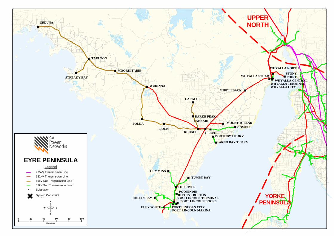
CEDUNA
COFFIN BAY
POLDA
STREAKY BAY
MOORKITABIE
TARLTON
ULEY SOUTH
CUMMINS
PORT LINCOLN CITYPORT LINCOLN MARINA
POONINDIEPOINT BOSTON
TOD RIVER
LOCKRUDALL
PORT LINCOLN DOCKSPORT LINCOLN TERMINAL
TUMBY BAY
YADNARIE
CLEVE
ARNO BAY 33/11KV
BOOTHBY 11/33KV
COWELLMOUNT MILLAR
WUDINNA
CARALUE
DARKE PEAK
MIDDLEBACK
STONY POINTWHYALLA STUART
WHYALLA CITY
WHYALLA NORTH
WHYALLA TERMINALWHYALLA CENTRAL
UPPERNORTH
YORKEPENINSULA
EYRE PENINSULALegend
275kV Transmission Line132kV Transmission Line66kV Sub Transmission Line33kV Sub Transmission LineSubstation
0 20 40 60 80 100
Kilometres
System Constraint.

Distribution Annual Planning Report
Version 1.1 Page 151
Substation: Port Lincoln Terminal 132/33kV
Region: Eyre Peninsula
(ETC) Transmission Category: 3
Number of Transformers: 3
Total Nameplate Rating (MVA): 75 MVA
Actuals
Year 2009/2010 2010/2011 2011/2012 2012/2013 2013/2014
Sum
mer
MW 37.8 39.7 29.4 34.9 32.4
MVAr 15.8 19.2 10.7 11.5 8.0
MVA 41.0 44.1 31.3 36.7 33.3
PF 0.92 0.90 0.94 0.95 0.97
Year 2009 2010 2011 2012 2013
Win
ter MW 29.5 31.8 32.3 32.9 31.8
MVAr 6.3 6.7 6.1 2.8 5.0
MVA 30.2 32.5 32.9 33.0 32.2
PF 0.98 0.98 0.98 1.00 0.99
Forecast
Sum
mer
10% POE Forecast 2014/2015 2015/2016 2016/2017 2017/2018 2018/2019
MW 33.4 33.3 33.1 33.1 33.1
MVAr 10.4 10.3 10.3 10.3 10.3
MVA 34.9 34.9 34.7 34.7 34.6
PF 0.96 0.96 0.96 0.96 0.96
Firm Delivery Capacity (MVA) 64.0 64.0 64.0 64.0 64.0
System Limitation (Y/N) N N N N N
Hrs per annum > 95% of Peak Load (hrs) 2
Year Former Step Change (MVA) Year Future Step Change (10% POE MVA)

Distribution Annual Planning Report
Version 1.1 Page 152
Substation: Whyalla Central 132/33kV
Region: Eyre Peninsula
(ETC) Transmission Category: 4
Number of Transformers: 2
Total Nameplate Rating (MVA): 240 MVA
Actuals
Year 2009/2010 2010/2011 2011/2012 2012/2013 2013/2014
Sum
mer
MW 91.3 91.9 83.6 66.4 71.1
MVAr 44.2 44.5 29.8 22.3 20.6
MVA 101.4 102.1 88.7 70.0 74.0
PF 0.90 0.90 0.94 0.95 0.96
Year 2009 2010 2011 2012 2013
Win
ter MW 68.2 78.0 80.0 68.9 69.1
MVAr 28.0 30.3 38.2 31.8 24.7
MVA 73.7 83.7 88.7 76.0 73.4
PF 0.92 0.93 0.90 0.91 0.94
Forecast*
Sum
mer
10% POE Forecast 2014/2015 2015/2016 2016/2017 2017/2018 2018/2019
MW 73.5 73.4 73.3 73.2 73.1
MVAr 29.2 29.2 29.5 29.4 29.7
MVA 79.1 79.0 79.0 78.9 78.9
PF 0.93 0.93 0.93 0.93 0.93
Firm Delivery Capacity (MVA) 120 120 120 120 120
System Limitation (Y/N) N N N N N
Hrs per annum > 95% of Peak Load (hrs) 6
Year Former Step Change (MVA) Year Future Step Change (10% POE MVA)
*Customer embedded generation included in forecast on the 10%POE basis.

Distribution Annual Planning Report
Version 1.1 Page 153
Substation: Wudinna 132/66kV
Region: Eyre Peninsula
(ETC) Transmission Category: 2
Number of Transformers: 2
Total Nameplate Rating (MVA): 50 MVA
Actuals
Year 2009/2010 2010/2011 2011/2012 2012/2013 2013/2014
Sum
mer
MW 15.4 15.7 14.2 14.1 15.3
MVAr 2.2 2.2 2.0 2.0 0.7
MVA 15.6 15.8 14.3 14.2 15.3
PF 0.99 0.99 0.99 0.99 1.00
Year 2009 2010 2011 2012 2013
Win
ter MW 9.6 10.5 10.9 10.7 10.2
MVAr 1.4 1.5 1.6 3.1 3.7
MVA 9.7 10.7 11.0 11.1 10.9
PF 0.99 0.99 0.99 0.96 0.94
Forecast
Sum
mer
10% POE Forecast 2014/2015 2015/2016 2016/2017 2017/2018 2018/2019
MW 13.9 13.8 13.6 13.5 13.3
MVAr 0.4 0.4 0.4 0.4 0.4
MVA 13.9 13.8 13.6 13.5 13.3
PF 1.00 1.00 1.00 1.00 1.00
Firm Delivery Capacity (MVA) 25 25 25 25 25
System Limitation (Y/N) N N N N N
Hrs per annum > 95% of Peak Load (hrs) 5
Year Former Step Change (MVA) Year Future Step Change (10% POE MVA)

Distribution Annual Planning Report
Version 1.1 Page 154
Substation: Yadnarie 132/66kV
Region: Eyre Peninsula
(ETC) Transmission Category: 2
Number of Transformers: 2
Total Nameplate Rating (MVA): 40 MVA
Actuals
Year 2009/2010 2010/2011 2011/2012 2012/2013 2013/2014
Sum
mer
MW 11.5 9.5 7.7 8.0 8.2
MVAr 0.9 0.2 0.0 1.4 1.3
MVA 11.5 9.5 7.7 8.1 8.3
PF 1.00 1.00 1.00 0.98 0.99
Year 2009 2010 2011 2012 2013
Win
ter MW 7.1 7.4 6.3 6.8 5.8
MVAr 5.0 2.8 2.4 3.1 4.0
MVA 8.6 7.9 6.7 6.1 7.0
PF 0.82 0.94 0.93 0.89 0.82
Forecast
Sum
mer
10% POE Forecast 2014/2015 2015/2016 2016/2017 2017/2018 2018/2019
MW 7.8 7.8 7.8 7.8 7.9
MVAr 1.2 1.2 1.2 1.2 1.2
MVA 7.9 7.9 7.9 7.9 8.0
PF 0.99 0.99 0.99 0.99 0.99
Firm Delivery Capacity (MVA) 27.4 27.4 27.4 27.4 27.4
System Limitation (Y/N) N N N N N
Hrs per annum > 95% of Peak Load (hrs) 2
Year Former Step Change (MVA) Year Future Step Change (10% POE MVA)

Distribution Annual Planning Report
Version 1.1 Page 155
Substation: Arno Bay 33/11kV
Region: Eyre Peninsula
Number of Feeders: 1
Number of Transformers: 1
Total Nameplate Rating (MVA): 3 MVA
Actuals
Year 2009/2010 2010/2011 2011/2012 2012/2013 2013/2014
Sum
mer
MW 1.0 1.0 1.0 0.9 0.8
MVAr 0.4 0.4 0.4 0.3 0.3
MVA 1.1 1.1 1.1 1.0 0.8
PF 0.93 0.93 0.93 0.95 0.92
Year 2009 2010 2011 2012 2013
Win
ter MW 0.7 0.8 0.7 0.8 0.7
MVAr 0.3 0.3 0.3 0.1 0.3
MVA 0.7 0.9 0.8 0.8 0.7
PF 0.93 0.93 0.93 0.99 0.92
Forecast
Sum
mer
10% POE Forecast 2014/2015 2015/2016 2016/2017 2017/2018 2018/2019
MW 0.8 0.8 0.7 0.7 0.7
MVAr 0.3 0.3 0.3 0.3 0.3
MVA 0.8 0.8 0.8 0.8 0.8
PF 0.92 0.92 0.92 0.92 0.92
Total Capacity (MVA) 3.9 3.9 3.9 3.9 3.9
50% POE Forecast
MW 0.8 0.8 0.8 0.8 0.8
MVAr 0.3 0.3 0.3 0.3 0.3
MVA 0.8
0.8
0.9
0.9
0.9 PF 0.92 0.92 0.92 0.92 0.92
Firm Delivery Capacity (MVA) 0.0 0.0 0.0 0.0 0.0
Transfer Capacity (MVA) 0.0
0.0
0.0
0.0
0.0 System Limitation (Y/N) Y* Y* Y* Y* Y*
Hrs per annum > 95% of Peak Load (hrs) 5
Year Former Step Change (MVA) Year Future Step Change (10% POE MVA)
2009/10 +0.3MVA Customer load increase
*Within planning criteria risk margin
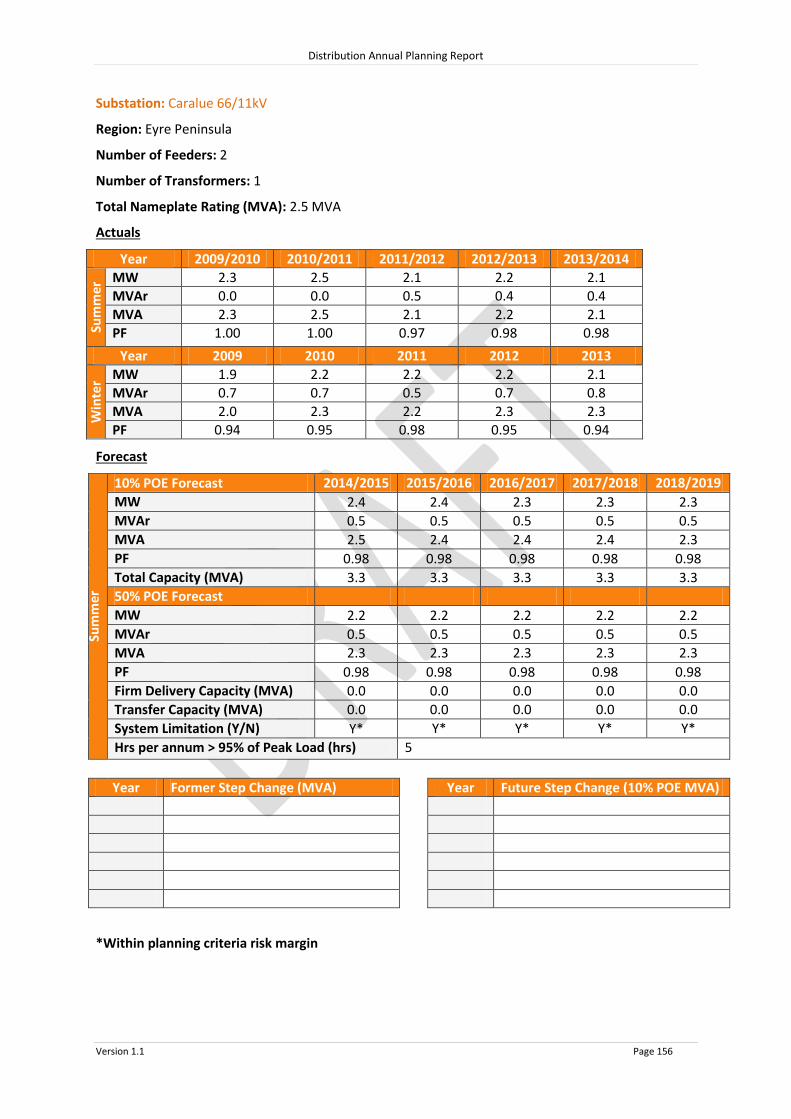
Distribution Annual Planning Report
Version 1.1 Page 156
Substation: Caralue 66/11kV
Region: Eyre Peninsula
Number of Feeders: 2
Number of Transformers: 1
Total Nameplate Rating (MVA): 2.5 MVA
Actuals
Year 2009/2010 2010/2011 2011/2012 2012/2013 2013/2014
Sum
mer
MW 2.3 2.5 2.1 2.2 2.1
MVAr 0.0 0.0 0.5 0.4 0.4
MVA 2.3 2.5 2.1 2.2 2.1
PF 1.00 1.00 0.97 0.98 0.98
Year 2009 2010 2011 2012 2013
Win
ter MW 1.9 2.2 2.2 2.2 2.1
MVAr 0.7 0.7 0.5 0.7 0.8
MVA 2.0 2.3 2.2 2.3 2.3
PF 0.94 0.95 0.98 0.95 0.94
Forecast
Sum
mer
10% POE Forecast 2014/2015 2015/2016 2016/2017 2017/2018 2018/2019
MW 2.4 2.4 2.3 2.3 2.3
MVAr 0.5 0.5 0.5 0.5 0.5
MVA 2.5 2.4 2.4 2.4 2.3
PF 0.98 0.98 0.98 0.98 0.98
Total Capacity (MVA) 3.3 3.3 3.3 3.3 3.3
50% POE Forecast
MW 2.2 2.2 2.2 2.2 2.2
MVAr 0.5 0.5 0.5 0.5 0.5
MVA 2.3
2.3
2.3
2.3
2.3 PF 0.98 0.98 0.98 0.98 0.98
Firm Delivery Capacity (MVA) 0.0 0.0 0.0 0.0 0.0
Transfer Capacity (MVA) 0.0
0.0
0.0
0.0
0.0 System Limitation (Y/N) Y* Y* Y* Y* Y*
Hrs per annum > 95% of Peak Load (hrs) 5
Year Former Step Change (MVA) Year Future Step Change (10% POE MVA)
*Within planning criteria risk margin

Distribution Annual Planning Report
Version 1.1 Page 157
Substation: Ceduna 66/11kV
Region: Eyre Peninsula
Number of Feeders: 3
Number of Transformers: 2
Total Nameplate Rating (MVA): 10 MVA
Actuals
Year 2009/2010 2010/2011 2011/2012 2012/2013 2013/2014
Sum
mer
MW 7.1 6.5 6.4 6.5 7.2
MVAr 3.2 1.3 1.6 1.1 1.6
MVA 7.8 6.6 6.5 6.6 7.4
PF 0.91 0.98 0.97 0.99 0.98
Year 2009 2010 2011 2012 2013
Win
ter MW 4.9 5.4 6.0 5.8 5.5
MVAr 1.3 1.4 0.3 0.2 0.0
MVA 5.0 5.6 6.0 5.8 5.5
PF 0.97 0.97 1.00 1.00 1.00
Forecast
Sum
mer
10% POE Forecast 2014/2015 2015/2016 2016/2017 2017/2018 2018/2019
MW 7.2 7.1 7.0 6.9 6.8
MVAr 1.3 1.3 1.3 1.3 1.2
MVA 7.3 7.2 7.1 7.0 6.9
PF 0.98 0.98 0.98 0.98 0.98
Total Capacity (MVA) 14.2 14.2 14.2 14.2 14.2
50% POE Forecast
MW 6.4 6.3 6.2 6.1 6.0
MVAr 1.2 1.1 1.1 1.1 1.1
MVA 6.5
6.4
6.3
6.2
6.1 PF 0.98 0.98 0.98 0.98 0.98
Firm Delivery Capacity (MVA) 7.5 7.5 7.5 7.5 7.5
Transfer Capacity (MVA) 0.0
0.0
0.0
0.0
0.0 System Limitation (Y/N) N N N N N
Hrs per annum > 95% of Peak Load (hrs) 5
Year Former Step Change (MVA) Year Future Step Change (10% POE MVA)
2009/10 +0.4MVA Customer load increase
2010/11 Capacitor Bank restored to service

Distribution Annual Planning Report
Version 1.1 Page 158
Substation: Cleve 66/33kV
Region: Eyre Peninsula
Number of Feeders: 0
Number of Transformers: 1
Total Nameplate Rating (MVA): 12.5 MVA
Actuals
Year 2009/2010 2010/2011 2011/2012 2012/2013 2013/2014
Sum
mer
MW N/A 2.6 2.2 2.4 2.7
MVAr N/A 0.4 0.1 0.2 0.5
MVA N/A 2.6 2.2 2.4 2.8
PF N/A 0.99 1.00 1.00 0.98
Year 2009 2010 2011 2012 2013
Win
ter MW N/A 1.8 1.6 1.8 1.7
MVAr N/A 0.2 0.1 0.2 0.3
MVA N/A 1.8 1.6 1.8 1.7
PF N/A 0.99 1.00 0.99 0.99
Forecast
Sum
mer
10% POE Forecast 2014/2015 2015/2016 2016/2017 2017/2018 2018/2019
MW 2.2 2.3 2.3 2.3 2.3
MVAr 0.3 0.3 0.3 0.3 0.3
MVA 2.3 2.3 2.3 2.3 2.3
PF 0.99 0.99 0.99 0.99 0.99
Total Capacity (MVA) 17.8 17.8 17.8 17.8 17.8
50% POE Forecast
MW 1.9 1.8 1.7 1.7 1.6
MVAr 0.2 0.2 0.2 0.2 0.2
MVA 1.9
1.8
1.7
1.7
1.6 PF 0.99 0.99 0.99 0.99 0.99
Firm Delivery Capacity (MVA) 0.0 0.0 0.0 0.0 0.0
Transfer Capacity (MVA) 5.7
5.9
6.2
6.5
6.8 System Limitation (Y/N) N N N N N
Hrs per annum > 95% of Peak Load (hrs) 5
Year Former Step Change (MVA) Year Future Step Change (10% POE MVA)
2009/10 +2.4MVA from Cleve 11kV

Distribution Annual Planning Report
Version 1.1 Page 159
Substation: Cleve 66/11kV
Region: Eyre Peninsula
Number of Feeders: 3
Number of Transformers: 2
Total Nameplate Rating (MVA): 5 MVA
Actuals
Year 2009/2010 2010/2011 2011/2012 2012/2013 2013/2014
Sum
mer
MW 6.3 3.2 2.7 2.7 2.7
MVAr 2.6 1.4 1.1 1.2 0.9
MVA 6.8 3.5 2.9 2.9 2.9
PF 0.92 0.91 0.92 0.92 0.95
Year 2009 2010 2011 2012 2013
Win
ter MW 4.3 2.6 2.2 2.3 2.2
MVAr 0.0 0.6 0.7 0.4 0.3
MVA 4.3 2.7 2.3 2.3 2.2
PF 1.00 0.98 0.96 0.99 0.99
Forecast
Sum
mer
10% POE Forecast 2014/2015 2015/2016 2016/2017 2017/2018 2018/2019
MW 2.5 2.6 2.6 2.6 2.7
MVAr 1.0 1.0 1.0 1.1 1.1
MVA 2.7 2.8 2.8 2.8 2.9
PF 0.93 0.93 0.93 0.93 0.93
Total Capacity (MVA) 6.5 6.5 6.5 6.5 6.5
50% POE Forecast
MW 2.3 2.4 2.5 2.6 2.6
MVAr 0.9 1.0 1.0 1.0 1.0
MVA 2.5
2.6
2.7
2.8
2.8 PF 0.93 0.93 0.93 0.93 0.93
Firm Delivery Capacity (MVA) 3.8 3.8 3.8 3.8 3.8
Transfer Capacity (MVA) 0.0
0.0
0.0
0.0
0.0 System Limitation (Y/N) N N N N N
Hrs per annum > 95% of Peak Load (hrs) 5
5Year Former Step Change (MVA) Year Future Step Change (10% POE MVA)
2009/10 -2.4MVA to Cleve 33kV

Distribution Annual Planning Report
Version 1.1 Page 160
Substation: Coffin Bay 33/11kV
Region: Eyre Peninsula
Number of Feeders: 1
Number of Transformers: 1
Total Nameplate Rating (MVA): 2.5 MVA
Actuals
Year 2009/2010 2010/2011 2011/2012 2012/2013 2013/2014
Sum
mer
MW 1.5 1.5 1.7 1.6 1.4
MVAr 0.6 0.6 0.8 0.4 0.4
MVA 1.6 1.6 1.9 1.7 1.5
PF 0.93 0.93 0.89 0.96 0.97
Year 2009 2010 2011 2012 2013
Win
ter MW 0.9 0.9 1.0 1.0 0.9
MVAr 0.2 0.1 0.2 0.4 0.1
MVA 0.9 0.9 1.0 1.0 0.9
PF 0.98 0.99 0.97 0.94 1.00
Forecast
Sum
mer
10% POE Forecast 2014/2015 2015/2016 2016/2017 2017/2018 2018/2019
MW 1.3 1.3 1.3 1.2 1.2
MVAr 0.4 0.4 0.4 0.4 0.3
MVA 1.4 1.4 1.3 1.3 1.3
PF 0.96 0.96 0.96 0.96 0.96
Total Capacity (MVA) 2.7 2.7 2.7 2.7 2.7
50% POE Forecast
MW 1.1 1.1 1.1 1.0 1.0
MVAr 0.3 0.3 0.3 0.3 0.3
MVA 1.2
1.1
1.1
1.1
1.0 PF 0.96 0.96 0.96 0.96 0.96
Firm Delivery Capacity (MVA) 0.0 0.0 0.0 0.0 0.0
Transfer Capacity (MVA) 0.0
0.0
0.0
0.0
0.0 System Limitation (Y/N) Y* Y* Y* Y* Y*
Hrs per annum > 95% of Peak Load (hrs) 5
Year Former Step Change (MVA) Year Future Step Change (10% POE MVA)
*Within planning criteria risk margin

Distribution Annual Planning Report
Version 1.1 Page 161
Substation: Cowell 33/11kV
Region: Eyre Peninsula
Number of Feeders: 1
Number of Transformers: 1
Total Nameplate Rating (MVA): 3 MVA
Actuals
Year 2009/2010 2010/2011 2011/2012 2012/2013 2013/2014
Sum
mer
MW 2.5 2.9 2.4 2.0 2.2
MVAr 0.7 1.1 0.2 0.4 0.4
MVA 2.6 3.1 2.4 2.1 2.2
PF 0.96 0.94 1.00 0.98 0.98
Year 2009 2010 2011 2012 2013
Win
ter MW 1.4 1.6 1.7 1.6 1.5
MVAr 0.5 0.6 0.3 0.7 0.0
MVA 1.5 1.8 1.7 1.8 1.5
PF 0.93 0.93 0.99 0.93 1.00
Forecast
Sum
mer
10% POE Forecast 2014/2015 2015/2016 2016/2017 2017/2018 2018/2019
MW 2.3 2.3 2.3 2.4 2.4
MVAr 0.8 0.8 0.8 0.9 0.9
MVA 2.4 2.5 2.5 2.5 2.6
PF 0.94 0.94 0.94 0.94 0.94
Total Capacity (MVA) 3.9 3.9 3.9 3.9 3.9
50% POE Forecast
MW 2.0 2.1 2.2 2.2 2.3
MVAr 0.7 0.8 0.8 0.8 0.8
MVA 2.2
2.2
2.3
2.4
2.4 PF 0.94 0.94 0.94 0.94 0.94
Firm Delivery Capacity (MVA) 0.0 0.0 0.0 0.0 0.0
Transfer Capacity (MVA) 0.0
0.0
0.0
0.0
0.0 System Limitation (Y/N) Y* Y* Y* Y* Y*
Hrs per annum > 95% of Peak Load (hrs) 5
Year Former Step Change (MVA) Year Future Step Change (10% POE MVA)
*Within planning criteria risk margin

Distribution Annual Planning Report
Version 1.1 Page 162
Substation: Cummins 33/11kV
Region: Eyre Peninsula
Number of Feeders: 2
Number of Transformers: 2
Total Nameplate Rating (MVA): 3 MVA
Actuals
Year 2009/2010 2010/2011 2011/2012 2012/2013 2013/2014
Sum
mer
MW 3.2 3.7 2.3 2.6 3.0
MVAr 0.7 1.5 1.0 0.6 0.8
MVA 3.3 4.0 2.5 2.7 3.1
PF 0.98 0.93 0.91 0.98 0.97
Year 2009 2010 2011 2012 2013
Win
ter MW 2.2 2.5 2.5 2.0 2.0
MVAr 0.9 0.6 0.5 0.3 0.5
MVA 2.4 2.6 2.5 2.0 2.0
PF 0.93 0.97 0.98 0.99 0.97
Forecast
Sum
mer
10% POE Forecast 2014/2015 2015/2016 2016/2017 2017/2018 2018/2019
MW 2.2 2.2 2.2 2.2 2.2
MVAr 0.7 0.7 0.7 0.7 0.7
MVA 2.3 2.3 2.3 2.3 2.3
PF 0.95 0.95 0.95 0.95 0.95
Total Capacity (MVA) 3.9 3.9 3.9 3.9 3.9
50% POE Forecast
MW 2.0 2.0 1.9 1.9 1.9
MVAr 0.6 0.6 0.6 0.6 0.6
MVA 2.1
2.1
2.0
2.0
2.0 PF 0.95 0.95 0.95 0.95 0.95
Firm Delivery Capacity (MVA) 2.3 2.3 2.3 2.3 2.3
Transfer Capacity (MVA) 0.0
0.0
0.0
0.0
0.0 System Limitation (Y/N) N N N N N
Hrs per annum > 95% of Peak Load (hrs) 5
Year Former Step Change (MVA) Year Future Step Change (10% POE MVA)
2009/10 +0.2MVA Customer load increase

Distribution Annual Planning Report
Version 1.1 Page 163
Substation: Little Swamp 33/11kV
Region: Eyre Peninsula
Number of Feeders: 1
Number of Transformers: 1
Total Nameplate Rating (MVA): 0.15 MVA
Actuals
Year 2009/2010 2010/2011 2011/2012 2012/2013 2013/2014
Sum
mer
MW N/A N/A N/A N/A N/A
MVAr N/A N/A N/A N/A N/A
MVA N/A N/A N/A N/A N/A
PF N/A N/A N/A N/A N/A
Year 2009 2010 2011 2012 2013
Win
ter MW N/A N/A N/A N/A N/A
MVAr N/A N/A N/A N/A N/A
MVA N/A N/A N/A N/A N/A
PF N/A N/A N/A N/A N/A
Forecast
Sum
mer
10% POE Forecast 2014/2015 2015/2016 2016/2017 2017/2018 2018/2019
MW 0.2 0.2 0.2 0.2 0.2
MVAr 0.1 0.1 0.1 0.1 0.1
MVA 0.2 0.2 0.2 0.2 0.2
PF 0.97 0.97 0.97 0.97 0.97
Total Capacity (MVA) 0.195 0.195 0.195 0.195 0.195
50% POE Forecast
MW 0.2 0.2 0.2 0.2 0.2
MVAr 0.1 0.1 0.1 0.1 0.1
MVA 0.21
0.21
0.21
0.21
0.21 PF 0.97 0.97 0.97 0.97 0.97
Firm Delivery Capacity (MVA) 0.0 0.0 0.0 0.0 0.0
Transfer Capacity (MVA) 0.0 0.0 0.0 0.0 0.0
System Limitation (Y/N) Y* Y* Y* Y* Y*
Hrs per annum > 95% of Peak Load (hrs) 9
Year Former Step Change (MVA) Year Future Step Change (10% POE MVA)
*Within planning criteria risk margin

Distribution Annual Planning Report
Version 1.1 Page 164
Substation: Point Boston 33/11kV
Region: Eyre Peninsula
Number of Feeders: 2
Number of Transformers: 1
Total Nameplate Rating (MVA): 6.25 MVA
Actuals
Year 2009/2010 2010/2011 2011/2012 2012/2013 2013/2014
Sum
mer
MW 1.1 0.9 0.8 0.8 0.8
MVAr 0.9 0.6 0.7 0.5 0.2
MVA 1.4 1.1 1.1 0.9 0.9
PF 0.76 0.84 0.75 0.86 0.97
Year 2009 2010 2011 2012 2013
Win
ter MW 0.8 1.0 0.9 0.8 0.7
MVAr 0.4 0.3 0.5 0.4 0.2
MVA 0.9 1.1 1.0 0.9 0.7
PF 0.86 0.95 0.89 0.89 0.96
Forecast
Sum
mer
10% POE Forecast 2014/2015 2015/2016 2016/2017 2017/2018 2018/2019
MW 0.8 0.8 0.8 0.8 0.8
MVAr 0.3 0.3 0.3 0.3 0.3
MVA 0.9 0.9 0.8 0.8 0.8
PF 0.94 0.94 0.94 0.94 0.94
Total Capacity (MVA) 8.0 8.0 8.0 8.0 8.0
50% POE Forecast
MW 0.8 0.8 0.8 0.8 0.8
MVAr 0.3 0.3 0.3 0.3 0.3
MVA 0.8
0.8
0.8
0.8
0.8 PF 0.94 0.94 0.94 0.94 0.94
Firm Delivery Capacity (MVA) 0.0 0.0 0.0 0.0 0.0
Transfer Capacity (MVA) 0.0
0.0
0.0
0.0
0.0 System Limitation (Y/N) Y* Y* Y* Y* Y*
Hrs per annum > 95% of Peak Load (hrs) 9
Year Former Step Change (MVA) Year Future Step Change (10% POE MVA)
2010/11 Customer load decrease
2011/12 Customer load decrease
*Within planning criteria risk margin

Distribution Annual Planning Report
Version 1.1 Page 165
Substation: Poonindie 33/11kV
Region: Eyre Peninsula
Number of Feeders: 1
Number of Transformers: 1
Total Nameplate Rating (MVA): 1.5 MVA
Actuals
Year 2009/2010 2010/2011 2011/2012 2012/2013 2013/2014
Sum
mer
MW N/A N/A N/A 0.5 0.5
MVAr N/A N/A N/A 0.2 0.1
MVA N/A N/A N/A 0.6 0.5
PF N/A N/A N/A 0.93 0.97
Year 2009 2010 2011 2012 2013
Win
ter MW N/A N/A N/A N/A 0.5
MVAr N/A N/A N/A N/A 0.5
MVA N/A N/A N/A N/A 0.1
PF N/A N/A N/A N/A 0.97
Forecast
Sum
mer
10% POE Forecast 2014/2015 2015/2016 2016/2017 2017/2018 2018/2019
MW 0.8 0.8 0.8 0.8 0.8
MVAr 0.3 0.3 0.3 0.3 0.3
MVA 0.8 0.8 0.8 0.8 0.8
PF 0.95 0.95 0.95 0.95 0.95
Total Capacity (MVA) 2.0 2.0 2.0 2.0 2.0
50% POE Forecast
MW 0.7 0.7 0.7 0.7 0.7
MVAr 0.2 0.2 0.2 0.2 0.2
MVA 0.7
0.7
0.7
0.7
0.7 PF 0.95 0.95 0.95 0.95 0.95
Firm Delivery Capacity (MVA) 0.0 0.0 0.0 0.0 0.0
Transfer Capacity (MVA) 1.5
1.5
1.5
1.5
1.5 System Limitation (Y/N) N N N N N
Hrs per annum > 95% of Peak Load (hrs) 3
Year Former Step Change (MVA) Year Future Step Change (10% POE MVA)

Distribution Annual Planning Report
Version 1.1 Page 166
Substation: Port Lincoln City 33/11kV
Region: Eyre Peninsula
Number of Feeders: 3
Number of Transformers: 2
Total Nameplate Rating (MVA): 25 MVA
Actuals
Year 2009/2010 2010/2011 2011/2012 2012/2013 2013/2014
Sum
mer
MW 14.7 17.3 13.5 15.7 15.2
MVAr 4.3 5.3 4.6 4.4 3.4
MVA 15.3 18.1 14.3 16.3 15.6
PF 0.96 0.96 0.95 0.96 0.98
Year 2009 2010 2011 2012 2013
Win
ter MW 13.9 14.8 15.2 15.1 14.5
MVAr 2.0 1.7 4.2 0.9 0.5
MVA 14.1 14.9 15.7 15.1 14.5
PF 0.99 0.99 0.96 1.00 1.00
Forecast
Sum
mer
10% POE Forecast 2014/2015 2015/2016 2016/2017 2017/2018 2018/2019
MW 14.7 9.6 9.5 9.4 9.4
MVAr 4.3 2.8 2.8 2.7 2.7
MVA 15.3 10.0 9.9 9.8 9.8
PF 0.96 0.96 0.96 0.96 0.96
Total Capacity (MVA) 30.8 30.8 30.8 30.8 30.8
50% POE Forecast
MW 13.1 8.4 8.2 8.1 8.0
MVAr 3.8 2.5 2.4 2.4 2.3
MVA 13.7
8.8 8.6 8.5 8.3
PF 0.96 0.96 0.96 0.96 0.96
Firm Delivery Capacity (MVA) 15.4 15.4 15.4 15.4 15.4
Transfer Capacity (MVA) 2.1
2.1
2.2
2.2
2.2 System Limitation (Y/N) N N N N N
Hrs per annum > 95% of Peak Load (hrs) 5
Year Former Step Change (MVA) Year Future Step Change (10% POE MVA)
2015/16 -5.3MVA to Port Lincoln Marina

Distribution Annual Planning Report
Version 1.1 Page 167
Substation: Port Lincoln Docks 33/11kV
Region: Eyre Peninsula
Number of Feeders: 3
Number of Transformers: 1
Total Nameplate Rating (MVA): 12.5 MVA
Actuals
Year 2009/2010 2010/2011 2011/2012 2012/2013 2013/2014
Sum
mer
MW 9.9 11.0 8.6 10.0 8.6
MVAr 3.5 4.7 3.2 3.3 2.6
MVA 10.5 12.0 9.2 10.5 9.0
PF 0.94 0.92 0.94 0.95 0.96
Year 2009 2010 2011 2012 2013
Win
ter MW 8.4 9.1 10.8 10.9 10.5
MVAr 1.5 2.5 1.5 2.4 2.2
MVA 8.5 9.4 10.9 11.2 10.7
PF 0.98 0.97 0.99 0.98 0.98
Forecast
Sum
mer
10% POE Forecast 2014/2015 2015/2016 2016/2017 2017/2018 2018/2019
MW 9.2 7.0 6.9 6.8 6.8
MVAr 3.0 2.3 2.3 2.2 2.2
MVA 9.7 7.3 7.2 7.2 7.2
PF 0.95 0.95 0.95 0.95 0.95
Total Capacity (MVA) 12.3 12.3 12.3 12.3 12.3
50% POE Forecast
MW 8.3 6.2 6.1 6.0 5.9
MVAr 2.7 2.0 2.0 2.0 1.9
MVA 8.8
6.6 6.4 6.3 6.2
PF 0.95 0.95 0.95 0.95 0.95
Firm Delivery Capacity (MVA) 0.0 0.0 0.0 0.0 0.0
Transfer Capacity (MVA) 7.8
7.9
8.0
8.1
8.2 System Limitation (Y/N) Y* N N N N
Hrs per annum > 95% of Peak Load (hrs) 9
Year Former Step Change (MVA) Year Future Step Change (10% POE MVA)
2015/16 -2.3MVA to Port Lincoln Marina
*Within planning criteria risk margin
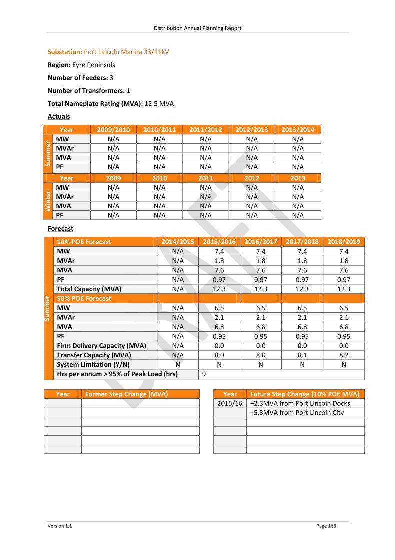
Distribution Annual Planning Report
Version 1.1 Page 168
Substation: Port Lincoln Marina 33/11kV
Region: Eyre Peninsula
Number of Feeders: 3
Number of Transformers: 1
Total Nameplate Rating (MVA): 12.5 MVA
Actuals
Year 2009/2010 2010/2011 2011/2012 2012/2013 2013/2014
Sum
mer
MW N/A N/A N/A N/A N/A
MVAr N/A N/A N/A N/A N/A
MVA N/A N/A N/A N/A N/A
PF N/A N/A N/A N/A N/A
Year 2009 2010 2011 2012 2013
Win
ter MW N/A N/A N/A N/A N/A
MVAr N/A N/A N/A N/A N/A
MVA N/A N/A N/A N/A N/A
PF N/A N/A N/A N/A N/A
Forecast
Sum
mer
10% POE Forecast 2014/2015 2015/2016 2016/2017 2017/2018 2018/2019
MW N/A 7.4 7.4 7.4 7.4
MVAr N/A 1.8 1.8 1.8 1.8
MVA N/A 7.6 7.6 7.6 7.6
PF N/A 0.97 0.97 0.97 0.97
Total Capacity (MVA) N/A 12.3 12.3 12.3 12.3
50% POE Forecast
MW N/A 6.5 6.5 6.5 6.5
MVAr N/A 2.1 2.1 2.1 2.1
MVA N/A 6.8 6.8 6.8 6.8
PF N/A 0.95 0.95 0.95 0.95
Firm Delivery Capacity (MVA) N/A 0.0 0.0 0.0 0.0
Transfer Capacity (MVA) N/A 8.0
8.0
8.1
8.2 System Limitation (Y/N) N N N N N
Hrs per annum > 95% of Peak Load (hrs) 9
Year Former Step Change (MVA) Year Future Step Change (10% POE MVA)
2015/16 +2.3MVA from Port Lincoln Docks
+5.3MVA from Port Lincoln City

Distribution Annual Planning Report
Version 1.1 Page 169
Substation: Streaky Bay 66/11kV
Region: Eyre Peninsula
Number of Feeders: 2
Number of Transformers: 2
Total Nameplate Rating (MVA): 5 MVA
Actuals
Year 2009/2010 2010/2011 2011/2012 2012/2013 2013/2014
Sum
mer
MW N/A N/A N/A 2.8 3.2
MVAr N/A N/A N/A 1.0 0.9
MVA N/A N/A N/A 3.0 3.4
PF N/A N/A N/A 0.94 0.96
Year 2009 2010 2011 2012 2013
Win
ter MW N/A N/A N/A 1.8 1.8
MVAr N/A N/A N/A 0.7 0.1
MVA N/A N/A N/A 1.9 1.8
PF N/A N/A N/A 0.93 1.00
Forecast
Sum
mer
10% POE Forecast 2014/2015 2015/2016 2016/2017 2017/2018 2018/2019
MW 3.0 3.0 3.0 3.0 3.0
MVAr 1.0 1.0 1.0 1.0 1.0
MVA 3.3 3.3 3.3 3.3 3.2
PF 0.95 0.95 0.95 0.95 0.95
Total Capacity (MVA) 6.5 6.5 6.5 6.5 6.5
50% POE Forecast
MW 2.8 2.8 2.8 2.8 2.8
MVAr 0.9 0.9 0.9 0.9 0.9
MVA 3.0
3.0
3.0
2.9
2.9 PF 0.95 0.95 0.95 0.95 0.95
Firm Delivery Capacity (MVA) 3.8 3.8 3.8 3.8 3.8
Transfer Capacity (MVA) 0.0
0.0
0.0
0.0
0.0 System Limitation (Y/N) N N N N N
Hrs per annum > 95% of Peak Load (hrs) 5
Year Former Step Change (MVA) Year Future Step Change (10% POE MVA)

Distribution Annual Planning Report
Version 1.1 Page 170
Substation: Tumby Bay 33/11kV
Region: Eyre Peninsula
Number of Feeders: 3
Number of Transformers: 2
Total Nameplate Rating (MVA): 5 MVA
Actuals
Year 2009/2010 2010/2011 2011/2012 2012/2013 2013/2014
Sum
mer
MW 2.6 N/A 2.6 2.4 N/A
MVAr 0.8 N/A 0.9 0.8 N/A
MVA 2.8 N/A 2.8 2.5 N/A
PF 0.95 N/A 0.95 0.95 N/A
Year 2009 2010 2011 2012 2013
Win
ter MW 2.7 N/A 2.9 3.1 3.1
MVAr 0.2 N/A 0.9 1.0 1.1
MVA 2.7 N/A 3.0 3.3 3.3
PF 1.00 N/A 0.95 0.95 0.94
Forecast
Sum
mer
10% POE Forecast 2014/2015 2015/2016 2016/2017 2017/2018 2018/2019
MW 2.5 2.5 2.5 2.5 2.6
MVAr 0.9 0.9 0.9 0.9 0.9
MVA 2.6 2.6 2.7 2.7 2.7
PF 0.94 0.94 0.94 0.94 0.94
Total Capacity (MVA) 5.4 5.4 5.4 5.4 5.4
50% POE Forecast
MW 2.2 2.2 2.3 2.3 2.3
MVAr 0.8 0.8 0.8 0.8 0.8
MVA 2.3
2.4
2.4
2.4
2.5 PF 0.94 0.94 0.94 0.94 0.94
Firm Delivery Capacity (MVA) 3.0 3.0 3.0 3.0 3.0
Transfer Capacity (MVA) 0.0
0.0
0.0
0.0
0.0 System Limitation (Y/N) N N N N N
Hrs per annum > 95% of Peak Load (hrs) 5
Year Former Step Change (MVA) Year Future Step Change (10% POE MVA)
2009/10 +0.6MVA Customer load increase

Distribution Annual Planning Report
Version 1.1 Page 171
Substation: Whyalla City 33/11kV
Region: Eyre Peninsula
Number of Feeders: 7
Number of Transformers: 2
Total Nameplate Rating (MVA): 20 MVA
Actuals
Year 2009/2010 2010/2011 2011/2012 2012/2013 2013/2014
Sum
mer
MW 20.8 19.9 18.0 19.0 20.2
MVAr 7.8 6.3 0.5 3.2 0.4
MVA 22.2 20.9 18.0 19.2 20.2
PF 0.94 0.95 1.00 0.99 1.00
Year 2009 2010 2011 2012 2013
Win
ter MW 12.7 14.0 12.5 13.0 12.7
MVAr 3.5 3.6 2.7 3.0 2.6
MVA 13.2 14.4 12.8 13.3 12.9
PF 0.96 0.97 0.98 0.98 0.98
Forecast
Sum
mer
10% POE Forecast 2014/2015 2015/2016 2016/2017 2017/2018 2018/2019
MW 20.7 20.7 20.7 20.6 20.6
MVAr 2.0 2.0 2.0 2.0 2.0
MVA 20.8 20.8 20.8 20.7 20.7
PF 1.00 1.00 1.00 1.00 1.00
Total Capacity (MVA) 28.5 28.5 28.5 28.5 28.5
50% POE Forecast
MW 18.3 18.2 18.2 18.2 18.1
MVAr 1.8 1.8 1.8 1.8 1.8
MVA 18.3 18.3 18.3 18.2 18.2
PF 1.00 1.00 1.00 1.00 1.00
Firm Delivery Capacity (MVA) 15.0 15.0 15.0 15.0 15.0
Transfer Capacity (MVA) 7.0
7.0
7.0
7.0
7.0 System Limitation (Y/N) N N N N N
Hrs per annum > 95% of Peak Load (hrs) 7
Year Former Step Change (MVA) Year Future Step Change (10% POE MVA)
2011/12 9MVAr Capacitor Bank installed

Distribution Annual Planning Report
Version 1.1 Page 172
Substation: Whyalla Stuart 33/11kV
Region: Eyre Peninsula
Number of Feeders: 5
Number of Transformers: 2
Total Nameplate Rating (MVA): 25 MVA
Actuals
Year 2009/2010 2010/2011 2011/2012 2012/2013 2013/2014
Sum
mer
MW 17.0 17.8 15.3 16.7 16.6
MVAr 5.7 6.2 5.0 4.9 4.3
MVA 17.9 18.9 16.1 17.3 17.1
PF 0.95 0.94 0.95 0.96 0.97
Year 2009 2010 2011 2012 2013
Win
ter MW 10.0 11.3 10.6 11.1 10.5
MVAr 2.5 2.4 2.3 2.3 1.7
MVA 10.2 11.6 10.8 11.3 10.6
PF 0.97 0.98 0.98 0.98 0.99
Forecast
Sum
mer
10% POE Forecast 2014/2015 2015/2016 2016/2017 2017/2018 2018/2019
MW 17.4 17.2 17.1 16.9 16.8
MVAr 5.1 5.1 5.0 5.0 5.0
MVA 18.1 18.0 17.8 17.7 17.5
PF 0.96 0.96 0.96 0.96 0.96
Total Capacity (MVA) 31.0 31.0 31.0 31.0 31.0
50% POE Forecast
MW 15.6 15.4 15.3 15.2 15.0
MVAr 4.6 4.5 4.5 4.5 4.4
MVA 16.2
16.1
15.9
15.8
15.7 PF 0.96 0.96 0.96 0.96 0.96
Firm Delivery Capacity (MVA) 16.6 16.6 16.6 16.6 16.6
Transfer Capacity (MVA) 6.9
6.9
7.0
7.0
7.1 System Limitation (Y/N) N N N N N
Hrs per annum > 95% of Peak Load (hrs) 5
Year Former Step Change (MVA) Year Future Step Change (10% POE MVA)
2010/11 +0.2MVA Customer load increase

Distribution Annual Planning Report
Version 1.1 Page 173
Substation: Wudinna 66/11kV
Region: Eyre Peninsula
Number of Feeders: 2
Number of Transformers: 4
Total Nameplate Rating (MVA): 4 MVA
Actuals
Year 2009/2010 2010/2011 2011/2012 2012/2013 2013/2014
Sum
mer
MW N/A N/A N/A 2.0 2.6
MVAr N/A N/A N/A 0.3 0.4
MVA N/A N/A N/A 2.0 2.6
PF N/A N/A N/A 0.99 0.99
Year 2009 2010 2011 2012 2013
Win
ter MW N/A N/A N/A 2.2 1.6
MVAr N/A N/A N/A 0.7 0.1
MVA N/A N/A N/A 2.3 1.6
PF N/A N/A N/A 0.95 1.00
Forecast
Sum
mer
10% POE Forecast 2014/2015 2015/2016 2016/2017 2017/2018 2018/2019
MW 2.2 2.1 2.1 2.1 2.0
MVAr 0.2 0.2 0.2 0.2 0.2
MVA 2.2 2.1 2.1 2.1 2.1
PF 1.00 1.00 1.00 1.00 1.00
Total Capacity (MVA) 5.2 5.2 5.2 5.2 5.2
50% POE Forecast
MW 1.9 1.9 1.9 1.9 1.9
MVAr 0.2 0.2 0.2 0.2 0.2
MVA 2.0
1.9
1.9
1.9
1.9 PF 1.00 1.00 1.00 1.00 1.00
Firm Delivery Capacity (MVA) 4.5 4.5 4.5 4.5 4.5
Transfer Capacity (MVA) 0.0
0.0
0.0
0.0
0.0 System Limitation (Y/N) N N N N N
Hrs per annum > 95% of Peak Load (hrs) 5
Year Former Step Change (MVA) Year Future Step Change (10% POE MVA)

Distribution Annual Planning Report
Version 1.1 Page 174
8.8.3 Eyre Peninsula Non-SCADA Substations 10% POE Forecast
2014/2015 2015/2016 2016/2017 2017/2018 2018/2019
Substation No of
TFs
TF Nameplate
Rating (MVA)
Total Capacity (MVA)
10% POE Forecast (MVA)
10% POE Forecast (MVA)
10% POE Forecast (MVA)
10% POE Forecast (MVA)
10% POE Forecast (MVA)
Darke Peak 1 1.0 1.3 0.7 0.7 0.7 0.7 0.7
Lock 1 1.0 1.3 0.9 0.9 0.9 0.9 0.9
Lock 66kV Reg 20 25.0 0.9 0.9 0.9 0.9 0.9
Moorkitabie 1 1.0 1.3 0.8 0.8 0.8 0.8 0.8
Polda 1 1.0 1.3 0.6 0.6 0.6 0.5 0.5
Rudall 1 0.5 0.7 0.1 0.1 0.1 0.1 0.1
Stony Point* 1 2.5 2.5 0.7 0.7 0.7 0.7 0.7
Tarlton 2 1.0 1.3 0.7 0.7 0.7 0.7 0.7
Uley 1 1.0 1.3 1.3 1.3 1.3 1.3 1.3
* Small Connection Point System Limitations: Nil

Distribution Annual Planning Report
Version 1.1 Page 175
8.8.4 Eyre Peninsula 66kV Sub-transmission Lines
Line Name - From
To Total
Capacity^ (MVA)
Forecast 2014/2015
MVA
Forecast 2015/2016
MVA
Forecast 2016/2017
MVA
Forecast 2017/2018
MVA
Forecast 2018/2019
MVA
66KV LINES ON EYRE PENINSULA
YADNARIE CLEVE 10.3 5.0 5.0 5.1 5.1 5.1
YADNARIE RUDALL 10.3 4.4 4.4 4.4 4.4 4.3
RUDALL DARKE PEAK 10.3 3.1 3.1 3.1 3.1 3.0
DARKE PEAK CARALUE 10.3 2.4 2.4 2.4 2.4 2.3
RUDALL LOCK 10.3 1.2 1.2 1.2 1.2 1.2
LOCK POLDA 10.3 0.0 0.0 0.0 0.0 0.0
POLDA WUDINNA 10.3 0.9 0.9 0.8 0.8 0.8
WUDINNA MOORKITABIE 53.2 12.0 11.9 11.8 11.7 11.6
MOORKITABIE TARLTON 53.2 11.2 11.1 11.0 10.9 10.8
TARLTON STREAKY BAY 31.0 3.2 3.2 3.2 3.1 3.1
TARLTON CEDUNA 53.2 7.3 7.2 7.2 7.1 7.0
^ The published rating is based on a thermal limit or a limit required to maintain adequate clearances and does not take into account voltage limitations on the network which may further reduce the published rating. System Limitations: Nil

Distribution Annual Planning Report
Version 1.1 Page 176
8.8.5 Eyre Peninsula 33kV Sub-transmission Lines
Line Name - From
To Total
Capacity^ (MVA)
Forecast 2014/2015
MVA
Forecast 2015/2016
MVA
Forecast 2016/2017
MVA
Forecast 2017/2018
MVA
Forecast 2018/2019
MVA
1 2 3 4 5
33kV lines ex Whyalla
Whyalla Central # Whyalla City No 1 26.5 11.2 11.2 11.1 11.1 11.1
Whyalla Central # Whyalla City No 2 27.7 9.7 9.7 9.6 9.6 9.6
Whyalla Central # Whyalla Stuart 27.7 18.1 18.0 17.8 17.6 17.5
Whyalla Central # Whyalla North Tee 24.6 1.1 1.0 1.0 1.0 1.0
Whyalla North Tee Whyalla North 12.5 1.1 1.0 1.0 1.0 1.0
# = Industrial Weathered Line 33kV lines ex Pt Lincoln Pt Lincoln Terminal Pt Lincoln City Tee 15.5 9.7 9.7 9.8 9.8 9.8
Pt Lincoln City Tee Pt Lincoln City 40.5 0.0 0.0 0.0 0.0 0.0
Pt Lincoln Terminal Pt Lincoln City 28.9 15.3 15.3 15.3 15.3 15.4
Pt Lincoln City Tee Pt Lincoln Docks 40.5 9.7 9.7 9.7 9.8 9.8
Pt Lincoln Terminal Poonindie Tee 20.3 8.1 8.1 8.1 8.1 8.2
Poonindie Tee Todd River 20.3 6.4 6.4 6.4 6.5 6.5
Poonindie Tee Poonindie 12.9 1.7 1.7 1.7 1.7 1.7
Poonindie Point Boston 13.2 0.9 0.9 0.8 0.8 0.8
Todd River Cummins 5.1 2.3 2.3 2.3 2.3 2.3
Todd River Tumby Bay 5.1 2.6 2.7 2.7 2.7 2.7
Pt Lincoln Terminal Uley Sth Tee 7.1 5.2 5.2 5.2 5.2 5.2
Uley Sth Tee Uley Sth 5.1 2.4 2.5 2.5 2.5 2.5
Uley Sth Tee Uley 5.2 2.7 2.7 2.7 2.7 2.7
Uley Coffin Bay 5.2 1.4 1.4 1.3 1.3 1.3
33kV lines ex Cleve
Cleve Cowell 15 2.26 2.3 2.3 2.3 2.3
Boothby Arno Bay 15 0.82 0.8 0.8 0.8 0.8
^ The published rating is based on a thermal limit or a limit required to maintain adequate clearances and does not take into account voltage limitations on the network which may further reduce the published rating. System Limitations: Nil

Distribution Annual Planning Report
Version 1.1 Page 177
8.9 Upper North Regional Development Plan
Upper North Region
The SA Power Networks’ Upper North region includes the Upper North areas Port Augusta and Port Pirie. Connection Points are located at Baroota, Davenport West, Leigh Creek South, Mount Gunson, Neuroodla, and the meshed connection points of Bungama & Port Pirie substations. SA Power Networks’ Distribution Network Electricity is supplied to the various towns and localities throughout the Upper North Region via Zone Substations. These Zone Substations are operated at either 66,000 Volts stepped down to 11,000 Volts or 33,000 Volts stepped down to 11,000 Volts. Customers are supplied from SA Power Networks’ distribution system via 11kV and 19kV primary distribution feeders, which are connected to Zone Substations. These feeders are extended and upgraded as required to meet customer demand and customer connection requests. Large customer projects may require a Zone Substation upgrade as well as feeder modifications, therefore SA Power Networks should be notified as early as possible during the planning stages of a project so that customer connection requirements can be met. There are no system limitations forecast for the primary distribution feeders under normal conditions in the Upper North Region in the next two years.
8.9.1 Upper North SCADA Substations
Source Connection Point Associated SCADA Substations
Baroota Bungama 11kV
Booleroo Centre
Wirrabara Forest
Davenport West Port Augusta
Pt Augusta West No. 1
Pt Augusta West No. 2
Stirling North 1
Stirling North 2
Port Pirie / Bungama Jamestown
Peterborough
Port Broughton
Port Pirie South

PORT AUGUSTAPORT AUGUSTA WEST
PORT BROUGHTON
PORT PIRIE SOUTH
BAROOTA
PORT PIRIE
DAVENPORT WEST
MOUNT GUNSON
LEIGH CREEK SOUTH
BUNGAMA
STIRLING NORTH
WILMINGTON
NEW STIRLING NORTH
QUORN
CRYSTAL BROOK
GLADSTONE
MURRAYTOWN
JAMESTOWN
PETERBOROUGH
ORROROO
NEUROODLA
HAWKER
275kV Transmission Line132kV Transmission Line66kV Sub Transmission Line33kV Sub Transmission LineSubstation
Legend
UPPER NORTH
EYRE PENINSULA
0 10 20 30 40 50
Kilometres
MIDNORTH
System Limitation.

Distribution Annual Planning Report
Version 1.1 Page 179
Substation: Baroota 132/33kV
Region: Upper North
(ETC) Transmission Category: 1, 2 in 2017
Number of Transformers: 1
Total Nameplate Rating (MVA): 10 MVA
Actuals
Year 2009/2010 2010/2011 2011/2012 2012/2013 2013/2014
Sum
mer
MW 8.7 8.5 7.3 7.7 7.8
MVAr 2.2 1.5 1.0 1.1 0.9
MVA 9.0 8.6 7.4 7.8 7.8
PF 0.97 0.99 0.99 0.99 0.99
Year 2009 2010 2011 2012 2013
Win
ter MW 5.9 6.6 5.9 6.0 5.9
MVAr 0.1 0.0 0.0 0.7 0.8
MVA 5.9 6.6 5.9 6.0 6.0
PF 1.00 1.00 1.00 1.00 0.99
Forecast
Sum
mer
10% POE Forecast 2014/2015 2015/2016 2016/2017 2017/2018 2018/2019
MW 7.7 7.7 7.7 7.7 7.6
MVAr 1.0 1.0 1.0 1.0 1.0
MVA 7.8 7.8 7.8 7.7 7.7
PF 0.99 0.99 0.99 0.99 0.99
Firm Delivery Capacity (MVA) 0 0 0 0 0
System Limitation (Y/N) Y* Y* Y* Y* Y*
Hrs per annum > 95% of Peak Load (hrs) 4
Year Former Step Change (MVA) Year Future Step Change (10% POE MVA)
* N-1 capacity not required by ETC until 2017

Distribution Annual Planning Report
Version 1.1 Page 180
Baroota 132/33kV Connection Point
System Limitation
Baroota 132/33kV Connection Point has one 10MVA 132/33kV transformer and is located near the township of Baroota, approximately 7km north of Port Germein.
The ETC has changed the security standard for Baroota from Category 1 to Category 2 (requires N-1 Capacity) from 2017. As a consequence this Connection Point Substation will not be compliant with the ETC from 2017 onwards unless it is upgraded by both ElectraNet and SA Power Networks.
The Transmission Company (Electranet) are managing the Regulatory Test process for the Transmission Connection Point, refer to http://www.electranet.com.au/network/current-and-planned-projects/mid-north/baroota-substation-upgrade/
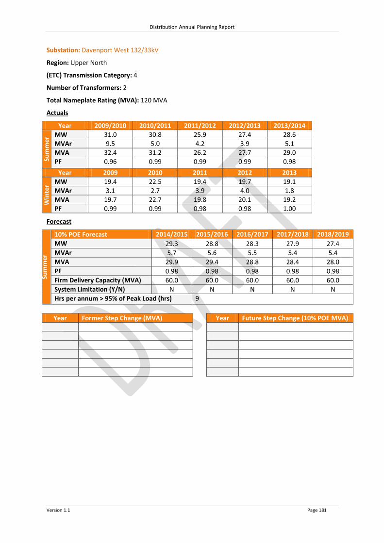
Distribution Annual Planning Report
Version 1.1 Page 181
Substation: Davenport West 132/33kV
Region: Upper North
(ETC) Transmission Category: 4
Number of Transformers: 2
Total Nameplate Rating (MVA): 120 MVA
Actuals
Year 2009/2010 2010/2011 2011/2012 2012/2013 2013/2014
Sum
mer
MW 31.0 30.8 25.9 27.4 28.6
MVAr 9.5 5.0 4.2 3.9 5.1
MVA 32.4 31.2 26.2 27.7 29.0
PF 0.96 0.99 0.99 0.99 0.98
Year 2009 2010 2011 2012 2013
Win
ter MW 19.4 22.5 19.4 19.7 19.1
MVAr 3.1 2.7 3.9 4.0 1.8
MVA 19.7 22.7 19.8 20.1 19.2
PF 0.99 0.99 0.98 0.98 1.00
Forecast
Sum
mer
10% POE Forecast 2014/2015 2015/2016 2016/2017 2017/2018 2018/2019
MW 29.3 28.8 28.3 27.9 27.4
MVAr 5.7 5.6 5.5 5.4 5.4
MVA 29.9 29.4 28.8 28.4 28.0
PF 0.98 0.98 0.98 0.98 0.98
Firm Delivery Capacity (MVA) 60.0 60.0 60.0 60.0 60.0
System Limitation (Y/N) N N N N N
Hrs per annum > 95% of Peak Load (hrs) 9
Year Former Step Change (MVA) Year Future Step Change (10% POE MVA)

Distribution Annual Planning Report
Version 1.1 Page 182
Substation: Leigh Creek South 132/33kV
Region: Upper North
(ETC) Transmission Category: 1
Number of Transformers: 2
Total Nameplate Rating (MVA): 10 MVA
Actuals
Year 2009/2010 2010/2011 2011/2012 2012/2013 2013/2014
Sum
mer
MW 1.7 1.6 1.4 1.5 1.5
MVAr 0.1 0.5 0.5 0.5 0.4
MVA 1.7 1.7 1.5 1.5 1.6
PF 1.00 0.95 0.95 0.95 0.96
Year 2009 2010 2011 2012 2013
Win
ter MW 1.3 1.4 1.4 1.3 1.3
MVAr 0.1 0.1 0.1 1.0 0.4
MVA 1.3 1.4 1.4 1.3 1.4
PF 1.00 1.00 1.00 1.00 0.95
Forecast
Sum
mer
10% POE Forecast 2014/2015 2015/2016 2016/2017 2017/2018 2018/2019
MW 1.5 1.5 1.5 1.5 1.5
MVAr 0.5 0.5 0.5 0.5 0.5
MVA 1.6 1.6 1.6 1.5 1.5
PF 0.95 0.95 0.95 0.95 0.95
Total Capacity (MVA) 5.0 5.0 5.0 5.0 5.0
System Limitation (Y/N) N N N N N
Hrs per annum > 95% of Peak Load (hrs) 6
Year Former Step Change (MVA) Year Future Step Change (10% POE MVA)

Distribution Annual Planning Report
Version 1.1 Page 183
Substation: Mount Gunson 132/33kV
Region: Upper North
(ETC) Transmission Category: 1
Number of Transformers: 1
Total Nameplate Rating (MVA): 5 MVA
Actuals
Year 2009/2010 2010/2011 2011/2012 2012/2013 2013/2014
Sum
mer
MW 0.4 0.2 0.1 0.1 0.2
MVAr 0.1 0.1 0.0 0.0 0.0
MVA 0.4 0.2 0.2 0.2 0.2
PF 0.99 0.95 0.98 0.98 0.98
Year 2009 2010 2011 2012 2013
Win
ter MW 0.1 0.2 0.2 0.2 0.3
MVAr 0.1 0.1 0.1 0.0 0.2
MVA 0.1 0.2 0.2 0.2 0.3
PF 0.68 0.91 0.96 0.97 0.84
Forecast
Sum
mer
10% POE Forecast 2014/2015 2015/2016 2016/2017 2017/2018 2018/2019
MW 0.2 0.2 0.2 0.2 0.2
MVAr 0.1 0.1 0.1 0.1 0.1
MVA 0.2 0.2 0.2 0.2 0.2
PF 0.84 0.84 0.84 0.84 0.84
Total Capacity (MVA) 5.0 5.0 5.0 5.0 5.0
System Limitation (Y/N) N N N N N
Hrs per annum > 95% of Peak Load (hrs) 18
Year Former Step Change (MVA) Year Future Step Change (10% POE MVA)

Distribution Annual Planning Report
Version 1.1 Page 184
Substation: Neuroodla 132/33kV
Region: Upper North
(ETC) Transmission Category: 1
Number of Transformers: 1
Total Nameplate Rating (MVA): 5 MVA
Actuals
Year 2009/2010 2010/2011 2011/2012 2012/2013 2013/2014
Sum
mer
MW 0.9 0.9 0.9 0.9 0.9
MVAr 0.4 0.5 0.4 0.4 0.4
MVA 1.0 1.1 0.9 1.0 1.0
PF 0.90 0.90 0.90 0.90 0.90
Year 2009 2010 2011 2012 2013
Win
ter MW 0.8 0.9 0.9 0.8 0.8
MVAr 0.4 0.5 0.4 0.4 0.4
MVA 0.9 1.0 0.9 0.9 0.9
PF 0.90 0.90 0.90 0.90 0.90
Forecast
Sum
mer
10% POE Forecast 2014/2015 2015/2016 2016/2017 2017/2018 2018/2019
MW 0.9 0.9 0.9 0.9 0.9
MVAr 0.4 0.4 0.4 0.4 0.4
MVA 1.0 1.0 1.0 1.0 1.0
PF 0.90 0.90 0.90 0.90 0.90
Total Capacity (MVA) 5.0 5.0 5.0 5.0 5.0
System Limitation (Y/N) N N N N N
Hrs per annum > 95% of Peak Load (hrs) 5
Year Former Step Change (MVA) Year Future Step Change (10% POE MVA)

Distribution Annual Planning Report
Version 1.1 Page 185
Substation: Port Pirie / Bungama 132/33kV
Region: Upper North
(ETC) Transmission Category: 4G
Number of Transformers: 3
Total Nameplate Rating (MVA): 180 MVA
Actuals
Year 2009/2010 2010/2011 2011/2012 2012/2013 2013/2014
Sum
mer
MW 84.9 72.0 73.5 69.6 66.6
MVAr 26.5 25.7 19.5 13.4 12.6
MVA 88.9 76.4 76.0 70.9 67.8
PF 0.95 0.94 0.97 0.98 0.98
Year 2009 2010 2011 2012 2013
Win
ter MW 60.5 72.0 66.2 60.4 60.6
MVAr 21.3 25.8 24.0 30.1 12.3
MVA 64.1 76.5 70.4 67.5 61.9
PF 0.94 0.94 0.94 0.90 0.98
Forecast
Sum
mer
10% POE Forecast 2014/2015 2015/2016 2016/2017 2017/2018 2018/2019
MW 55.3 55.5 70.7 70.9 71.2
MVAr 19.7 20.0 27.3 27.6 27.7
MVA 58.7 59.0 75.8 76.1 76.4
PF 0.94 0.94 0.93 0.93 0.93
Firm Delivery Capacity (MVA) 87.0* 87.0* 87.0* 87.0* 87.0*
System Limitation (Y/N) N N N N N
Year Former Step Change (MVA) Year Future Step Change (10% POE MVA)
2014/15 -15MVA temporary customer load decrease
2016/17 +15MVA customer load increase
* Includes Industrial and Rural Connection Point Capacities

Distribution Annual Planning Report
Version 1.1 Page 186
Substation: Booleroo Centre 33/11kV
Region: Upper North
Number of Feeders: 1
Number of Transformers: 1
Total Nameplate Rating (MVA): 1 MVA
Actuals
Year 2009/2010 2010/2011 2011/2012 2012/2013 2013/2014
Sum
mer
MW N/A N/A N/A N/A N/A
MVAr N/A N/A N/A N/A N/A
MVA N/A N/A N/A N/A N/A
PF N/A N/A N/A N/A N/A
Year 2009 2010 2011 2012 2013
Win
ter MW N/A N/A N/A N/A N/A
MVAr N/A N/A N/A N/A N/A
MVA N/A N/A N/A N/A N/A
PF N/A N/A N/A N/A N/A
Forecast
Sum
mer
10% POE Forecast 2014/2015 2015/2016 2016/2017 2017/2018 2018/2019
MW 0.7 0.7 0.7 0.7 0.7
MVAr 0.1 0.1 0.1 0.1 0.1
MVA 0.7 0.7 0.7 0.7 0.7
PF 0.99 0.99 0.99 0.99 0.99
Total Capacity (MVA) 1.3 1.3 1.3 1.3 1.3
50% POE Forecast
MW 0.6
0.6
0.6
0.6
0.6 MVAr 0.1
0.1
0.1
0.1
0.1
MVA 0.6
0.6
0.6
0.6
0.6 PF 0.99
0.99
0.99
0.99
0.99
Firm Delivery Capacity (MVA) 0.0 0.0 0.0 0.0 0.0
Transfer Capacity (MVA) 0.0
0.0
0.0
0.0
0.0 System Limitation (Y/N) N N N N N
Hrs per annum > 95% of Peak Load (hrs)
Year Former Step Change (MVA) Year Future Step Change (10% POE MVA)

Distribution Annual Planning Report
Version 1.1 Page 187
Substation: Bungama 33/11kV
Region: Upper North
Number of Feeders: 1
Number of Transformers: 2
Total Nameplate Rating (MVA): 1 MVA
Actuals
Year 2009/2010 2010/2011 2011/2012 2012/2013 2013/2014
Sum
mer
MW 1.1 1.1 1.0 0.8 0.9
MVAr 0.5 0.4 0.4 0.3 0.4
MVA 1.2 1.1 1.1 0.9 1.0
PF 0.93 0.93 0.93 0.93 0.93
Year 2009 2010 2011 2012 2013
Win
ter MW 0.8 0.9 0.7 0.7 N/A
MVAr 0.3 0.4 0.3 0.3 N/A
MVA 0.9 0.9 0.8 0.7 N/A
PF 0.93 0.92 0.92 0.93 N/A
Forecast
Sum
mer
10% POE Forecast 2014/2015 2015/2016 2016/2017 2017/2018 2018/2019
MW 0.8 0.8 0.8 0.8 0.8
MVAr 0.3 0.3 0.3 0.3 0.3
MVA 1.1 1.1 1.1 1.1 1.1
PF 0.93 0.93 0.93 0.93 0.93
Total Capacity (MVA) 1.3 1.3 1.3 1.3 1.3
50% POE Forecast
MW 0.7 0.7 0.7 0.7 0.7
MVAr 0.3 0.3 0.3 0.3 0.3
MVA 1.0
1.0 1.0 1.0 1.0
PF 0.93 0.93 0.93 0.93 0.93
Firm Delivery Capacity (MVA) 0.8 0.8 0.8 0.8 0.8
Transfer Capacity (MVA) 0.0
0.0
0.0
0.0
0.0 System Limitation (Y/N) Y* Y* Y* Y* Y*
Hrs per annum > 95% of Peak Load (hrs) 7
Year Former Step Change (MVA) Year Future Step Change (10% POE MVA)
*Within planning criteria risk margin

Distribution Annual Planning Report
Version 1.1 Page 188
Substation: Jamestown 33/11kV
Region: Upper North
Number of Feeders: 1
Number of Transformers: 2
Total Nameplate Rating (MVA): 3 MVA
Actuals
Year 2009/2010 2010/2011 2011/2012 2012/2013 2013/2014
Sum
mer
MW N/A 2.8 2.1 N/A N/A
MVAr N/A 1.1 0.8 N/A N/A
MVA N/A 3.0 2.3 N/A N/A
PF N/A 0.93 0.93 N/A N/A
Year 2009 2010 2011 2012 2013
Win
ter MW N/A N/A 2.0 2.0 2.2
MVAr N/A N/A 0.8 0.8 0.7
MVA N/A N/A 2.2 2.2 2.3
PF N/A N/A 0.93 0.93 0.98
Forecast
Sum
mer
10% POE Forecast 2014/2015 2015/2016 2016/2017 2017/2018 2018/2019
MW 3.0 3.0 3.0 3.0 3.0
MVAr 0.6 0.6 0.6 0.6 0.6
MVA 3.1 3.1 3.1 3.1 3.1
PF 0.98 0.98 0.98 0.98 0.98
Total Capacity (MVA) 3.9 3.9 3.9 3.9 3.9
50% POE Forecast
MW 2.7 2.7 2.7 2.7 2.7
MVAr 0.6 0.6 0.6 0.6 0.6
MVA 2.8
2.8
2.8
2.8
2.8 PF 0.98 0.98 0.98 0.98 0.98
Firm Delivery Capacity (MVA) 2.3 2.3 2.3 2.3 2.3
Transfer Capacity (MVA) 0.0
0.0
0.0
0.0
0.0 System Limitation (Y/N) Y* Y* Y* Y* Y*
Hrs per annum > 95% of Peak Load (hrs) 6
Year Former Step Change (MVA) Year Future Step Change (10% POE MVA)
*Within planning criteria risk margin

Distribution Annual Planning Report
Version 1.1 Page 189
Substation: Peterborough 33/11kV
Region: Upper North
Number of Feeders: 2
Number of Transformers: 2
Total Nameplate Rating (MVA): 5 MVA
Actuals
Year 2009/2010 2010/2011 2011/2012 2012/2013 2013/2014
Sum
mer
MW 2.5 2.3 1.9 1.9 2.1
MVAr 0.8 0.9 0.0 0.0 0.6
MVA 2.6 2.5 1.9 1.9 2.2
PF 0.95 0.93 1.00 1.00 0.96
Year 2009 2010 2011 2012 2013
Win
ter MW 2.2 2.3 2.2 2.2 2.1
MVAr 0.5 0.4 0.0 0.0 0.3
MVA 2.2 2.3 2.2 2.2 2.1
PF 0.98 0.98 1.00 1.00 0.99
Forecast
Sum
mer
10% POE Forecast 2014/2015 2015/2016 2016/2017 2017/2018 2018/2019
MW 1.9 1.9 1.9 1.9 1.9
MVAr 0.5 0.5 0.5 0.5 0.5
MVA 2.0 2.0 1.9 1.9 1.9
PF 0.97 0.97 0.97 0.97 0.97
Total Capacity (MVA) 6.2 6.2 6.2 6.2 6.2
50% POE Forecast
MW 1.7 1.7 1.7 1.6 1.6
MVAr 0.4 0.4 0.4 0.4 0.4
MVA 1.7
1.7
1.7
1.7
1.7 PF 0.97 0.97 0.97 0.97 0.97
Firm Delivery Capacity (MVA) 3.8 3.8 3.8 3.8 3.8
Transfer Capacity (MVA) 0.0
0.0
0.0
0.0
0.0 System Limitation (Y/N) N N N N N
Hrs per annum > 95% of Peak Load (hrs) 6
Year Former Step Change (MVA) Year Future Step Change (10% POE MVA)

Distribution Annual Planning Report
Version 1.1 Page 190
Substation: Port Augusta 33/11kV
Region: Upper North
Number of Feeders: 4
Number of Transformers: 2
Total Nameplate Rating (MVA): 25 MVA
Actuals
Year 2009/2010 2010/2011 2011/2012 2012/2013 2013/2014
Sum
mer
MW 17.3 17.9 15.4 13.8 15.0
MVAr 1.9 0.6 0.0 0.0 0.5
MVA 17.4 17.9 15.4 13.8 15.0
PF 0.99 1.00 1.00 1.00 1.00
Year 2009 2010 2011 2012 2013
Win
ter MW 9.6 12.2 10.8 10.2 9.5
MVAr 0.1 0.5 4.0 3.5 1.1
MVA 9.6 12.2 11.5 10.8 9.6
PF 1.00 1.00 0.94 0.94 0.99
Forecast
Sum
mer
10% POE Forecast 2014/2015 2015/2016 2016/2017 2017/2018 2018/2019
MW 15.2 14.9 14.6 14.3 14.0
MVAr 0.9 0.8 0.8 0.8 0.8
MVA 15.2 14.9 14.6 14.3 14.0
PF 1.00 1.00 1.00 1.00 1.00
Total Capacity (MVA) 28.4 28.4 28.4 28.4 28.4
50% POE Forecast
MW 14.0 13.7 13.4 13.1 12.8
MVAr 0.8 0.8 0.8 0.7 0.7
MVA 14.0 13.7 13.4 13.1 12.9
PF 1.00 1.00 1.00 1.00 1.00
Firm Delivery Capacity (MVA) 15.0 15.0 15.0 15.0 15.0
Transfer Capacity (MVA) 2.8
2.8
2.9
3.0
3.0 System Limitation (Y/N) N N N N N
Hrs per annum > 95% of Peak Load (hrs) 9
Year Former Step Change (MVA) Year Future Step Change (10% POE MVA)
2011/12 -1.8MVA to Port Augusta West

Distribution Annual Planning Report
Version 1.1 Page 191
Substation: Port Augusta West TF1 33/11kV
Region: Upper North
Number of Feeders: 2
Number of Transformers: 1
Total Nameplate Rating (MVA): 12.5 MVA
Actuals
Year 2009/2010 2010/2011 2011/2012 2012/2013 2013/2014
Sum
mer
MW 6.8 7.2 5.5 5.2 N/A
MVAr 1.6 1.6 1.2 1.8 N/A
MVA 7.0 7.3 5.6 5.5 N/A
PF 0.97 0.98 0.98 0.95 N/A
Year 2009 2010 2011 2012 2013
Win
ter MW 5.3 5.5 4.9 3.8 3.8
MVAr 0.1 0.1 0.3 1.2 0.6
MVA 5.3 5.5 4.9 4.0 3.8
PF 1.00 1.00 1.00 0.95 0.99
Forecast
Sum
mer
10% POE Forecast 2014/2015 2015/2016 2016/2017 2017/2018 2018/2019
MW 5.6 5.5 5.4 5.4 5.3
MVAr 1.0 1.0 1.0 1.0 1.0
MVA 5.7 5.6 5.5 5.5 5.4
PF 0.98 0.98 0.98 0.98 0.98
Total Capacity (MVA) 14.8 14.8 14.8 14.8 14.8
50% POE Forecast
MW 5.2 5.1 5.0 4.9 4.9
MVAr 1.0 0.9 0.9 0.9 0.9
MVA 5.3
5.2
5.1
5.0
4.9 PF 0.98 0.98 0.98 0.98 0.98
Firm Delivery Capacity (MVA) 0.0 0.0 0.0 0.0 0.0
Transfer Capacity (MVA) 9.5
9.6
9.7
9.9
10.0 System Limitation (Y/N) N N N N N
Hrs per annum > 95% of Peak Load (hrs) 7
Year Former Step Change (MVA) Year Future Step Change (10% POE MVA)
2011/12 -3.7MVA to Port Augusta West TF2
+1.8MVA from Port Augusta

Distribution Annual Planning Report
Version 1.1 Page 192
Substation: Port Augusta West TF2 33/11kV
Region: Upper North
Number of Feeders: 2
Number of Transformers: 1
Total Nameplate Rating (MVA): 12.5 MVA
Actuals
Year 2009/2010 2010/2011 2011/2012 2012/2013 2013/2014
Sum
mer
MW N/A N/A N/A 2.7 1.8
MVAr N/A N/A N/A 0.0 0.6
MVA N/A N/A N/A 2.7 1.8
PF N/A N/A N/A 1.00 0.95
Year 2009 2010 2011 2012 2013
Win
ter MW N/A N/A N/A 1.1 1.1
MVAr N/A N/A N/A 0.0 0.2
MVA N/A N/A N/A 1.1 1.1
PF N/A N/A N/A 1.00 0.99
Forecast
Sum
mer
10% POE Forecast 2014/2015 2015/2016 2016/2017 2017/2018 2018/2019
MW 1.7 1.7 1.6 1.6 1.6
MVAr 0.5 0.5 0.5 0.5 0.5
MVA 1.8 1.8 1.7 1.7 1.6
PF 0.96 0.96 0.96 0.96 0.96
Total Capacity (MVA) 14.8 14.8 14.8 14.8 14.8
50% POE Forecast
MW 1.6 1.5 1.5 1.4 1.4
MVAr 0.5 0.4 0.4 0.4 0.4
MVA 1.6
1.6
1.5
1.5
1.5 PF 0.96 0.96 0.96 0.96 0.96
Firm Delivery Capacity (MVA) 0.0 0.0 0.0 0.0 0.0
Transfer Capacity (MVA) 8.1
8.4
8.6
8.9
9.1 System Limitation (Y/N) N N N N N
Hrs per annum > 95% of Peak Load (hrs) 7
Year Former Step Change (MVA) Year Future Step Change (10% POE MVA)
2011/12 +3.7MVA from Port Augusta West TF1

Distribution Annual Planning Report
Version 1.1 Page 193
Substation: Port Broughton 33/11kV
Region: Upper North
Number of Feeders: 3
Number of Transformers: 2
Total Nameplate Rating (MVA): 5 MVA
Actuals
Year 2009/2010 2010/2011 2011/2012 2012/2013 2013/2014
Sum
mer
MW 4.4 3.9 3.7 3.4 3.1
MVAr 1.7 1.5 1.5 1.5 1.3
MVA 4.7 4.2 4.0 3.7 3.3
PF 0.93 0.93 0.93 0.92 0.92
Year 2009 2010 2011 2012 2013
Win
ter MW 2.3 2.4 2.1 2.4 2.0
MVAr 0.9 0.9 0.8 1.0 0.9
MVA 2.5 2.6 2.3 2.6 2.2
PF 0.93 0.93 0.93 0.92 0.92
Forecast
Sum
mer
10% POE Forecast 2014/2015 2015/2016 2016/2017 2017/2018 2018/2019
MW 2.9 2.9 2.9 2.8 2.8
MVAr 1.2 1.2 1.2 1.2 1.2
MVA 3.2 3.2 3.1 3.1 3.1
PF 0.92 0.92 0.92 0.92 0.92
Total Capacity (MVA) 5.4 5.4 5.4 5.4 5.4
50% POE Forecast
MW 2.5 2.5 2.4 2.4 2.4
MVAr 1.1 1.0 1.0 1.0 1.0
MVA 2.7
2.7
2.6
2.6
2.6 PF 0.92 0.92 0.92 0.92 0.92
Firm Delivery Capacity (MVA) 3.0 3.0 3.0 3.0 3.0
Transfer Capacity (MVA) 0.0
0.0
0.0
0.0
0.0 System Limitation (Y/N) N N N N N
Hrs per annum > 95% of Peak Load (hrs) 3
Year Former Step Change (MVA) Year Future Step Change (10% POE MVA)

Distribution Annual Planning Report
Version 1.1 Page 194
Substation: Port Pirie South 33/11kV
Region: Upper North
Number of Feeders: 5
Number of Transformers: 3
Total Nameplate Rating (MVA): 37.5 MVA
Actuals
Year 2009/2010 2010/2011 2011/2012 2012/2013 2013/2014
Sum
mer
MW 22.8 20.4 17.2 16.4 20.8
MVAr 9.3 8.3 7.3 6.1 7.1
MVA 24.6 22.1 18.7 17.5 22.0
PF 0.93 0.93 0.92 0.94 0.95
Year 2009 2010 2011 2012 2013
Win
ter MW 12.4 14.0 13.9 12.5 14.2
MVAr 3.8 4.3 3.4 3.2 2.9
MVA 13.0 14.6 14.3 12.9 14.4
PF 0.96 0.96 0.97 0.97 0.98
Forecast
Sum
mer
10% POE Forecast 2014/2015 2015/2016 2016/2017 2017/2018 2018/2019
MW 19.9 19.7 19.5 19.2 19.0
MVAr 7.2 7.2 7.1 7.0 6.9
MVA 21.2 21.0 20.7 20.5 20.3
PF 0.94 0.94 0.94 0.94 0.94
Total Capacity (MVA) 40.5 40.5 40.5 40.5 40.5
50% POE Forecast
MW 17.3 17.1 16.9 16.7 16.5
MVAr 6.3 6.2 6.1 6.1 6.0
MVA 18.4
18.2
18.0
17.7
17.5 PF 0.94 0.94 0.94 0.94 0.94
Firm Delivery Capacity (MVA) 27.7 27.7 27.7 27.7 27.7
Transfer Capacity (MVA) 0.0
0.0
0.0
0.0
0.0 System Limitation (Y/N) N N N N N
Hrs per annum > 95% of Peak Load (hrs) 7
Year Former Step Change (MVA) Year Future Step Change (10% POE MVA)
2011/12 +1.3MVA Customer load increase

Distribution Annual Planning Report
Version 1.1 Page 195
Substation: Stirling North 1 & 2 33/11kV
Region: Upper North
Number of Feeders: 2
Number of Transformers: 2
Total Nameplate Rating (MVA): 5.5 MVA
Actuals
Year 2009/2010 2010/2011 2011/2012 2012/2013 2013/2014
Sum
mer
MW N/A N/A N/A 2.8 2.4
MVAr N/A N/A N/A 0.5 0.6
MVA N/A N/A N/A 2.8 2.4
PF N/A N/A N/A 0.96 0.96
Year 2009 2010 2011 2012 2013
Win
ter MW N/A N/A N/A 2.2 2.2
MVAr N/A N/A N/A 0.5 0.6
MVA N/A N/A N/A 2.3 2.4
PF N/A N/A N/A 0.95 0.90
Forecast
Sum
mer
10% POE Forecast 2014/2015 2015/2016 2016/2017 2017/2018 2018/2019
MW 2.5 2.4 2.3 2.2 2.1
MVAr 1.1 1.1 1.0 1.0 0.9
MVA 2.7 2.6 2.5 2.4 2.3
PF 0.91 0.91 0.91 0.91 0.91
Total Capacity (MVA) 7.2 7.2 7.2 7.2 7.2
50% POE Forecast
MW 2.2 2.1 2.0 1.9 1.9
MVAr 1.0 1.0 0.9 0.9 0.8
MVA 2.4 2.3 2.2 2.1 2.0
PF 0.91 0.91 0.91 0.91 0.91
Firm Delivery Capacity (MVA) 0.0 0.0 0.0 0.0 0.0
Transfer Capacity (MVA) 3.8 3.8 3.8 3.8 3.8
System Limitation (Y/N) N N N N N
Hrs per annum > 95% of Peak Load (hrs) 6
Year Former Step Change (MVA) Year Future Step Change (10% POE MVA)

Distribution Annual Planning Report
Version 1.1 Page 196
Substation: Wirrabara Forest 33/11kV
Region: Upper North
Number of Feeders: 1
Number of Transformers: 1
Total Nameplate Rating (MVA): 1 MVA
Actuals
Year 2009/2010 2010/2011 2011/2012 2012/2013 2013/2014
Sum
mer
MW N/A N/A N/A N/A N/A
MVAr N/A N/A N/A N/A N/A
MVA N/A N/A N/A N/A N/A
PF N/A N/A N/A N/A N/A
Year 2009 2010 2011 2012 2013
Win
ter MW N/A N/A N/A N/A N/A
MVAr N/A N/A N/A N/A N/A
MVA N/A N/A N/A N/A N/A
PF N/A N/A N/A N/A N/A
Forecast
Sum
mer
10% POE Forecast 2014/2015 2015/2016 2016/2017 2017/2018 2018/2019
MW 0.8 0.8 0.8 0.8 0.8
MVAr 0.2 0.2 0.2 0.2 0.2
MVA 0.8 0.8 0.8 0.8 0.8
PF 0.98 0.98 0.98 0.98 0.98
Total Capacity (MVA) 1.3 1.3 1.3 1.3 1.3
50% POE Forecast
MW 0.7
0.7
0.7
0.7
0.7 MVAr 0.1
0.1
0.1
0.1
0.1
MVA 0.7
0.7
0.7
0.7
0.7 PF 0.98
0.98
0.98
0.98
0.98
Firm Delivery Capacity (MVA) 0.0 0.0 0.0 0.0 0.0
Transfer Capacity (MVA) 0.0
0.0
0.0
0.0
0.0 System Limitation (Y/N) Y* Y* Y* Y* Y*
Hrs per annum > 95% of Peak Load (hrs) 6
Year Former Step Change (MVA) Year Future Step Change (10% POE MVA)
*Within planning criteria risk margin

Distribution Annual Planning Report
Version 1.1 Page 197
8.9.3 Upper North Non-SCADA Substations 10% POE Forecast
2014/2015 2015/2016 2016/2017 2017/2018 2018/2019
Substation No of
TFs
TF Nameplate
Rating (MVA)
Total Capacity (MVA)
10% POE Forecast (MVA)
10% POE Forecast (MVA)
10% POE Forecast (MVA)
10% POE Forecast (MVA)
10% POE Forecast (MVA)
Baroota 1 0.5 0.7 0.3 0.3 0.3 0.3 0.3
Booleroo Centre 1 1.0 1.3 0.7 0.7 0.7 0.7 0.7
Booyoolie 1 0.15 0.2 0.02 0.02 0.02 0.02 0.02
Caltowie 1 0.2 0.3 0.1 0.1 0.1 0.1 0.1
Crystal Brook 2 2.0 2.6 2.1 2.1 2.1 2.1 2.1
Fullarville 1 0.2 0.3 0.03 0.03 0.03 0.03 0.03
Gladstone 2 4.0 4.8 2.5 2.5 2.5 2.5 2.5
Gladstone 33kV Reg 1 10.0 12.5 5.8 5.8 5.8 5.8 5.8
Hawker 2 1.0 1.3 0.9 0.9 0.9 0.9 0.9
Leigh Creek South 2 5.0 6.2 1.6 1.6 1.6 1.5 1.5
Melrose 1 0.5 0.7 0.3 0.3 0.3 0.3 0.3
Murraytown Reg 1 10.0 12.5 5.4 5.4 5.4 5.3 5.3
Orroroo 2 2.0 2.6 1.5 1.5 1.5 1.5 1.5
Port Germein 1 1.0 1.3 1.1 1.1 1.1 1.1 1.1
Quorn 1 2.5 3.3 2.1 2.1 2.0 2.0 2.0

Distribution Annual Planning Report
Version 1.1 Page 198
2014/2015 2015/2016 2016/2017 2017/2018 2018/2019
Substation No of
TFs
TF Nameplate
Rating (MVA)
Total Capacity (MVA)
10% POE Forecast (MVA)
10% POE Forecast (MVA)
10% POE Forecast (MVA)
10% POE Forecast (MVA)
10% POE Forecast (MVA)
Wilmington 2 1.0 1.3 0.8 0.8 0.8 0.8 0.8
Wirrabara Forest 1 1.0 1.3 0.8 0.8 0.8 0.8 0.8
Wirrabara South 1 0.1 0.1 0.1 0.1 0.1 0.1 0.1
Wongyarra 1 0.2 0.3 0.1 0.1 0.1 0.1 0.1
Yongala 1 0.3 0.4 0.1 0.1 0.1 0.1 0.1
System Limitations: Nil

Distribution Annual Planning Report
Version 1.1 Page 199
8.9.4 Upper North 33kV Sub-transmission Lines
Line Name - From To Total
Capacity^ (MVA)
Forecast 2014/2015
MVA
Forecast 2015/2016
MVA
Forecast 2016/2017
MVA
Forecast 2017/2018
MVA
Forecast 2018/2019
MVA
33kV lines ex Davenport West
Davenport West Stirling Nth Tee 20.1 5.8 5.5 5.3 5.2 5.1
Davenport West Pt Augusta No1 19.9 13.9 14.9 14.9 14.9 14.9
Davenport West Pt Augusta West Tee 19.9 13.9 11.2 10.9 10.5 10.1
Stirling Nth Tee Stirling Nth 10.4 5.8 5.5 5.3 5.2 5.1
Stirling Nth Quorn 3.9 2.8 2.8 2.7 2.7 2.7
Pt Augusta West Tee# #
Pt Augusta West 20.4 13.3 10.9 10.6 10.4 10.1
Pt Augusta West Tee# #
Pt Augusta 23 7.2 7.6 7.6 7.5 7.4
Pt Augusta West Pandurra 3.9 3.4 3.4 3.5 3.6 3.7 # = Industrial Weathered Line
33kV lines ex Baroota
Baroota Baroota Tee 20.3 8.9 8.8 8.8 8.8 8.7
Baroota Tee Bungama 5.1 3.5 3.4 3.4 3.4 3.4
Baroota Tee Murraytown Tee 9.8 5.4 5.4 5.4 5.3 5.3
Murraytown Tee Murraytown 9.8 5.4 5.4 5.4 5.3 5.3
Murraytown Gladstone 3.4 1.2 1.2 1.2 1.2 1.2
Murraytown Orroroo 3.9 2.9 2.9 2.9 2.8 2.8
Murraytown Melrose 3.4 1.4 1.4 1.3 1.3 1.3
Melrose Wilmington 4 0.8 0.8 0.8 0.8 0.8
33kV lines ex Bungama
Bungama # Pt Pirie South 30.1 11.8 11.8 11.9 11.9 12.0
Pt Pirie South # Pt Pirie 39.8 14.8 14.9 14.9 15.0 15.0
Bungama # Pt Pirie 30.1 8.8 8.8 8.9 8.9 8.9
Bungama Crystal Brook Tee 21.3 9.3 9.3 9.3 9.3 9.3
Crystal Brook Tee Gladstone 16 9.3 9.3 9.3 9.3 9.3
Crystal Brook Tee Crystal Brook 3.4 0.0 0.0 0.0 0.0 0.0
Gladstone Peterborough Tee 12.5 5.8 5.8 5.8 5.8 5.8
Peterborough Tee Jamestown 6.7 3.8 3.9 3.9 3.9 3.9
Jamestown Terowie 3.4 0.7 0.8 0.8 0.8 0.8
Peterborough Yongala 6.1 2.0 2.0 1.9 1.9 1.9
Yongala Peterborough Tee 6.1 2.0 2.0 1.9 1.9 1.9
Bungama Pt Broughton Tee 13 6.0 6.0 6.0 6.0 6.0
Pt Broughton Tee Pt Broughton 8.9 3.2 3.2 3.1 3.1 3.1
Pt Broughton Tee Collinsfield 6.7 0.0 0.0 0.0 0.0 0.0
Pt Broughton Tee Crystal Brook 3.9 2.8 2.8 2.9 2.9 2.9
# = Industrial Weathered Line

Distribution Annual Planning Report
Version 1.1 Page 200
^ The published rating is based on a thermal limit or a limit required to maintain adequate clearances and does not take into account voltage limitations on the network which may further reduce the published rating. System Limitations: Nil

Distribution Annual Planning Report
Version 1.1 Page 201
8.10 Barossa Regional Development Plan
The Barossa Region The SA Power Networks’ Barossa Region includes the Barossa Valley extending north to Stockwell, south to Williamstown and west to Dorrien and Lyndoch. There is one connection point in the Barossa, that being Dorrien Substation. SA Power Networks’ Distribution Network Electricity is supplied to the various towns and localities throughout the Barossa Region via Zone Substations. These Zone Substations are operated at 33,000 Volts stepped down to 11,000 or 7,600 Volts. Customers are supplied from SA Power Networks distribution system via 7.6kV, 11kV and 19kV primary distribution feeders, which are connected to distribution substations. These feeders are extended and upgraded as required to meet customer demand and customer connection requests. Large customer projects may require a distribution substation upgrade as well as feeder modifications, therefore SA Power Networks should be notified as early as possible during the planning stages of a project so that customer connection requirements can be met. There are no system limitations forecast for the primary distribution feeders under normal conditions in the Barossa Region in the next two years.
8.10.1 Barossa SCADA Substations
Source Connection Point Associated SCADA Substations
Dorrien Angaston
Barossa South
Dorrien 11kV
Lyndoch
Nuriootpa
Stockwell Williamstown South
Gomersal North

WILLIAMSTOWN SOUTH
SANDY CREEK
WILLIAMSTOWN
LYNDOCH
BAROSSASOUTH
DORRIENANGASTON
NURIOOTPA
STOCKWELL
BAROSSALegend
275kV Transmission Line132kV Transmission Line66kV Sub Transmission Line33kV Sub Transmission Line
MIDNORTH
.
0.0 2.5 5.0
Kilometres
Substation
System Limitation

Distribution Annual Planning Report
Version 1.1 Page 203
Substation: Dorrien 132/33kV
Region: Barossa
(ETC) Transmission Category: 4
Number of Transformers: 3
Total Nameplate Rating (MVA): 180 MVA
Actuals*
Year 2009/2010 2010/2011 2011/2012 2012/2013 2013/2014
Sum
mer
MW 57.7 52.3 55.7 57.3 56.6
MVAr 18.6 17.1 19.3 15.8 14.4
MVA 60.7 55.0 58.9 59.4 58.4
PF 0.95 0.95 0.94 0.96 0.97
Year 2009 2010 2011 2012 2013
Win
ter MW 46.3 43.5 46.7 46.3 39.7
MVAr 9.6 12.1 10.2 11.6 14.3
MVA 47.3 45.2 47.8 47.7 42.2
PF 0.98 0.96 0.98 0.97 0.94
Forecast*
Sum
mer
10% POE Forecast 2014/2015 2015/2016 2016/2017 2017/2018 2018/2019
MW 59.2 59.0 58.9 58.7 58.5
MVAr 19.2 19.1 19.0 19.0 18.9
MVA 62.3 62.0 61.9 61.7 61.4
PF 0.95 0.95 0.95 0.95 0.95
Firm Delivery Capacity (MVA) 156.0 156.0 156.0 156.0 156.0
System Limitation (Y/N) N N N N N
Hrs per annum > 95% of Peak Load (hrs) 6
Year Former Step Change (MVA) Year Future Step Change (10% POE MVA)
*Potential impact of below embedded generation has been removed from the above Actuals & excluded from Forecast: (i.e. generation output = 0)
Approximately 50MW of export embedded diesel generation at Angaston at 33kV

Distribution Annual Planning Report
Version 1.1 Page 204
Substation: Angaston 33/11kV
Region: Barossa
Number of Feeders: 6
Number of Transformers: 2
Total Nameplate Rating (MVA): 25 MVA
Actuals
Year 2009/2010 2010/2011 2011/2012 2012/2013 2013/2014
Sum
mer
MW 20.6 21.4 18.9 18.6 19.5
MVAr 0.0 0.0 4.8 6.2 2.3
MVA 20.6 21.4 19.5 19.6 19.6
PF 1.00 1.00 0.97 0.95 0.99
Year 2009 2010 2011 2012 2013
Win
ter MW 17.4 17.7 16.8 17.0 16.5
MVAr 1.9 2.2 0.0 0.0 1.5
MVA 17.5 17.8 16.8 17.0 16.5
PF 0.99 0.99 1.00 1.00 1.00
Forecast
Sum
mer
10% POE Forecast 2014/2015 2015/2016 2016/2017 2017/2018 2018/2019
MW 19.6 19.4 19.1 18.8 18.5
MVAr 3.9 3.8 3.8 3.7 3.6
MVA 20 19.7 19.4 19.1 18.9
PF 0.98 0.98 0.98 0.98 0.98
Total Capacity (MVA) 29.0 29.0 29.0 29.0 29.0
50% POE Forecast
MW 18.3 18.0 17.7 17.4 17.1
MVAr 3.6 3.5 3.5 3.4 3.4
MVA 18.7 18.4 18 17.7 17.4
PF 0.98 0.98 0.98 0.98 0.98
Firm Delivery Capacity (MVA) 15.2 15.2 15.2 15.2 15.2
Transfer Capacity (MVA) 2.8
2.9
2.9
2.9
2.9 System Limitation (Y/N) Y* Y* Y* Y* Y*
Hrs per annum > 95% of Peak Load (hrs) 9
Year Former Step Change (MVA) Year Future Step Change (10% POE MVA)
2011/12 +0.3MVA Customer load increase
10MVAr Capacitor Bank out of Service
2013/14 10MVAr Capacitor Bank Reinstated
*Within planning criteria risk margin
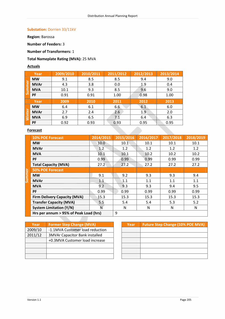
Distribution Annual Planning Report
Version 1.1 Page 205
Substation: Dorrien 33/11kV
Region: Barossa
Number of Feeders: 3
Number of Transformers: 1
Total Nameplate Rating (MVA): 25 MVA
Actuals
Year 2009/2010 2010/2011 2011/2012 2012/2013 2013/2014
Sum
mer
MW 9.1 8.5 8.5 9.4 9.0
MVAr 4.3 3.8 0.0 1.9 0.4
MVA 10.1 9.3 8.5 9.6 9.0
PF 0.91 0.91 1.00 0.98 1.00
Year 2009 2010 2011 2012 2013
Win
ter MW 6.4 6.1 6.6 6.1 6.0
MVAr 2.7 2.4 2.6 1.9 2.0
MVA 6.9 6.5 7.1 6.4 6.3
PF 0.92 0.93 0.93 0.95 0.95
Forecast
Sum
mer
10% POE Forecast 2014/2015 2015/2016 2016/2017 2017/2018 2018/2019
MW 10.0 10.1 10.1 10.1 10.1
MVAr 1.2 1.2 1.2 1.2 1.2
MVA 10.1 10.1 10.2 10.2 10.2
PF 0.99 0.99 0.99 0.99 0.99
Total Capacity (MVA) 27.2 27.2 27.2 27.2 27.2
50% POE Forecast
MW 9.1 9.2 9.3 9.3 9.4
MVAr 1.1 1.1 1.1 1.1 1.1
MVA 9.2 9.3 9.3 9.4 9.5
PF 0.99 0.99 0.99 0.99 0.99
Firm Delivery Capacity (MVA) 15.3 15.3 15.3 15.3 15.3
Transfer Capacity (MVA) 5.5
5.4
5.4
5.3
5.2 System Limitation (Y/N) N N N N N
Hrs per annum > 95% of Peak Load (hrs) 9
Year Former Step Change (MVA) Year Future Step Change (10% POE MVA)
2009/10 -1.1MVA Customer load reduction
2011/12 3MVAr Capacitor Bank installed
+0.3MVA Customer load increase

Distribution Annual Planning Report
Version 1.1 Page 206
Substation: Barossa South 33/11kV
Region: Barossa
Number of Feeders: 2
Number of Transformers: 1
Total Nameplate Rating (MVA): 6.25 MVA
Actuals
Year 2009/2010 2010/2011 2011/2012 2012/2013 2013/2014
Sum
mer
MW 6.6 5.9 6.6 6.4 6.5
MVAr 2.4 2.1 2.3 2.1 2.2
MVA 7.0 6.2 7.0 6.7 6.9
PF 0.94 0.94 0.94 0.95 0.95
Year 2009 2010 20119 2012 2013
Win
ter MW 3.8 3.8 3.9 3.8 3.4
MVAr 1.4 1.0 0.9 0.9 0.6
MVA 4.0 4.0 4.0 3.9 3.5
PF 0.94 0.97 0.98 0.97 0.98
Forecast
Sum
mer
10% POE Forecast 2014/2015 2015/2016 2016/2017 2017/2018 2018/2019
MW 7.0 7.0 7.0 7.0 7.0
MVAr 2.4 2.4 2.4 2.5 2.5
MVA 7.4 7.4 7.4 7.5 7.5
PF 0.94 0.94 0.94 0.94 0.94
Total Capacity (MVA) 8.9 8.9 8.9 8.9 8.9
50% POE Forecast
MW 6.5 6.5 6.5 6.5 6.5
MVAr 2.3 2.3 2.3 2.3 2.3
MVA 6.9
6.9
6.9
6.9
6.9 PF 0.94 0.94 0.94 0.94 0.94
Firm Delivery Capacity (MVA) 0.0 0.0 0.0 0.0 0.0
Transfer Capacity (MVA) 1.0
1.0
1.0
1.0
1.0 System Limitation (Y/N) Y Y Y Y Y
Hrs per annum > 95% of Peak Load (hrs) 9
Year Former Step Change (MVA) Year Future Step Change (10% POE MVA)

Distribution Annual Planning Report
Version 1.1 Page 207
Barossa South Substation
System Limitation
Barossa South 33/11kV Substation has one 6.25MVA 33/11kV transformer and is located near the township of Rowland Flat.
In the summer of 2014/15, up to 5.9MVA of customer load is forecasted to be unsupplied during a contingent event after all available load transfers have been implemented.
Potential solutions considered to address the system limitation include:
Upgrade the Barossa South Substation with a second transformer (preferred option);
Establish a new substation nearby with new 11kV feeder ties back to Barossa South Substation; or
Construct new 11kV feeder ties to surrounding substation to increase available transfers to existing adjacent Zone Substations.
Due to the extent of the overload during a contingent event, PF correction would not defer this system limitation. A load reduction of at least 2.9MVA would be required to defer the system limitation for a 12 month period.
A RIT-D is not expected to be required for this system limitation.

Distribution Annual Planning Report
Version 1.1 Page 208
Substation: Gomersal North 33/11kV
Region: Barossa
Number of Feeders: 1
Number of Transformers: 1
Total Nameplate Rating (MVA): 1 MVA
Actuals
Year 2009/2010 2010/2011 2011/2012 2012/2013 2013/2014
Sum
mer
MW N/A N/A N/A N/A N/A
MVAr N/A N/A N/A N/A N/A
MVA N/A N/A N/A N/A N/A
PF N/A N/A N/A N/A N/A
Year 2009 2010 2011 2012 2013
Win
ter MW N/A N/A N/A N/A N/A
MVAr N/A N/A N/A N/A N/A
MVA N/A N/A N/A N/A N/A
PF N/A N/A N/A N/A N/A
Forecast
Sum
mer
10% POE Forecast 2014/2015 2015/2016 2016/2017 2017/2018 2018/2019
MW 0.3 0.3 0.3 0.3 0.3
MVAr 0.1 0.1 0.1 0.1 0.1
MVA 0.3 0.3 0.3 0.3 0.3
PF 0.97 0.97 0.97 0.97 0.97
Total Capacity (MVA) 1.3 1.3 1.3 1.3 1.3
50% POE Forecast
MW 0.3
0.3
0.3
0.3
0.3 MVAr 0.1
0.1
0.1
0.1
0.1
MVA 0.3
0.3
0.3
0.3
0.3 PF 0.97
0.97
0.97
0.97
0.97
Firm Delivery Capacity (MVA) 0.0 0.0 0.0 0.0 0.0
Transfer Capacity (MVA) 0.0
0.0
0.0
0.0
0.0 System Limitation (Y/N) Y* Y* Y* Y* Y*
Hrs per annum > 95% of Peak Load (hrs) 9
Year Former Step Change (MVA) Year Future Step Change (10% POE MVA)
*Within planning criteria risk
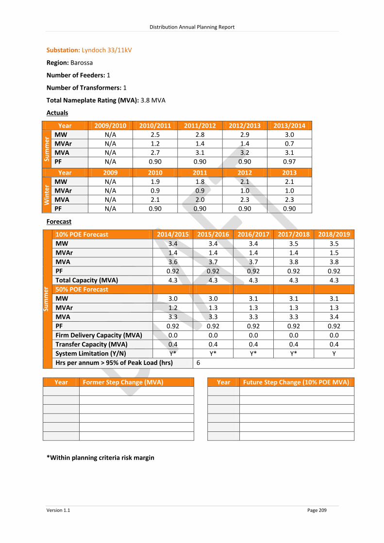
Distribution Annual Planning Report
Version 1.1 Page 209
Substation: Lyndoch 33/11kV
Region: Barossa
Number of Feeders: 1
Number of Transformers: 1
Total Nameplate Rating (MVA): 3.8 MVA
Actuals
Year 2009/2010 2010/2011 2011/2012 2012/2013 2013/2014
Sum
mer
MW N/A 2.5 2.8 2.9 3.0
MVAr N/A 1.2 1.4 1.4 0.7
MVA N/A 2.7 3.1 3.2 3.1
PF N/A 0.90 0.90 0.90 0.97
Year 2009 2010 2011 2012 2013
Win
ter MW N/A 1.9 1.8 2.1 2.1
MVAr N/A 0.9 0.9 1.0 1.0
MVA N/A 2.1 2.0 2.3 2.3
PF N/A 0.90 0.90 0.90 0.90
Forecast
Sum
mer
10% POE Forecast 2014/2015 2015/2016 2016/2017 2017/2018 2018/2019
MW 3.4 3.4 3.4 3.5 3.5
MVAr 1.4 1.4 1.4 1.4 1.5
MVA 3.6 3.7 3.7 3.8 3.8
PF 0.92 0.92 0.92 0.92 0.92
Total Capacity (MVA) 4.3 4.3 4.3 4.3 4.3
50% POE Forecast
MW 3.0 3.0 3.1 3.1 3.1
MVAr 1.2 1.3 1.3 1.3 1.3
MVA 3.3
3.3
3.3
3.3
3.4 PF 0.92 0.92 0.92 0.92 0.92
Firm Delivery Capacity (MVA) 0.0 0.0 0.0 0.0 0.0
Transfer Capacity (MVA) 0.4
0.4
0.4
0.4
0.4 System Limitation (Y/N) Y* Y* Y* Y* Y
Hrs per annum > 95% of Peak Load (hrs) 6
Year Former Step Change (MVA) Year Future Step Change (10% POE MVA)
*Within planning criteria risk margin

Distribution Annual Planning Report
Version 1.1 Page 210
Lyndoch Substation
System Limitation
Lyndoch 33/11kV Substation has one 3.8MVA 33/11kV transformer and is located near the township of Lyndoch.
In the summer of 2018/19, up to 3.0MVA of customer load is forecasted to be unsupplied during a contingent event after all available load transfers have been implemented.
Potential solutions considered to address the system limitation include:
Upgrade the Barossa South Substation with a second transformer (preferred option);
Establish a new substation nearby with new 11kV feeder ties back to Barossa South Substation; or
Construct new 11kV feeder ties to surrounding substation to increase available transfers to existing adjacent Zone Substations.
Due to the extent of the overload during a contingent event, PF correction would not defer this system limitation. A load reduction of at least 2.9MVA would be required to defer the system limitation for a 12 month period.
A RIT-D is not expected to be required for this system limitation.

Distribution Annual Planning Report
Version 1.1 Page 211
Substation: Nuriootpa 33/11kV
Region: Barossa
Number of Feeders: 2
Number of Transformers: 1
Total Nameplate Rating (MVA): 12.5 MVA
Actuals
Year 2009/2010 2010/2011 2011/2012 2012/2013 2013/2014
Sum
mer
MW 10.9 11.3 9.0 10.4 10.7
MVAr 3.0 2.6 1.9 4.2 2.2
MVA 11.3 11.6 9.2 11.2 10.9
PF 0.97 0.97 0.98 0.93 0.98
Year 2009 2010 2011 2012 2013
Win
ter MW 7.6 8.0 8.0 7.6 7.8
MVAr 0.1 2.5 0.0 2.2 2.1
MVA 7.6 8.4 8.0 7.9 8.0
PF 1.00 0.95 1.00 0.96 0.97
Forecast
Sum
mer
10% POE Forecast 2014/2015 2015/2016 2016/2017 2017/2018 2018/2019
MW 11.2 11.2 11.1 11.1 11.1
MVAr 3.6 3.6 3.6 3.6 3.6
MVA 11.8 11.7 11.7 11.7 11.7
PF 0.95 0.95 0.95 0.95 0.95
Total Capacity (MVA) 13.4 13.4 13.4 13.4 13.4
50% POE Forecast
MW 10.1 10.1 10.0 9.9 9.8
MVAr 3.3 3.3 3.2 3.2 3.2
MVA 10.7 10.6 10.5 10.4 10.3
PF 0.95 0.95 0.95 0.95 0.95
Firm Delivery Capacity (MVA) 0.0 0.0 0.0 0.0 0.0
Transfer Capacity (MVA) 4.7
4.7
8.7
8.6
8.5 System Limitation (Y/N) Y^ Y^ Y* Y* Y*
Hrs per annum > 95% of Peak Load (hrs) 7
Year Former Step Change (MVA) Year Future Step Change (10% POE MVA)
*Within planning criteria risk margin
^Solved by 2016 new feeder tie upgrade at Stockwell Substation
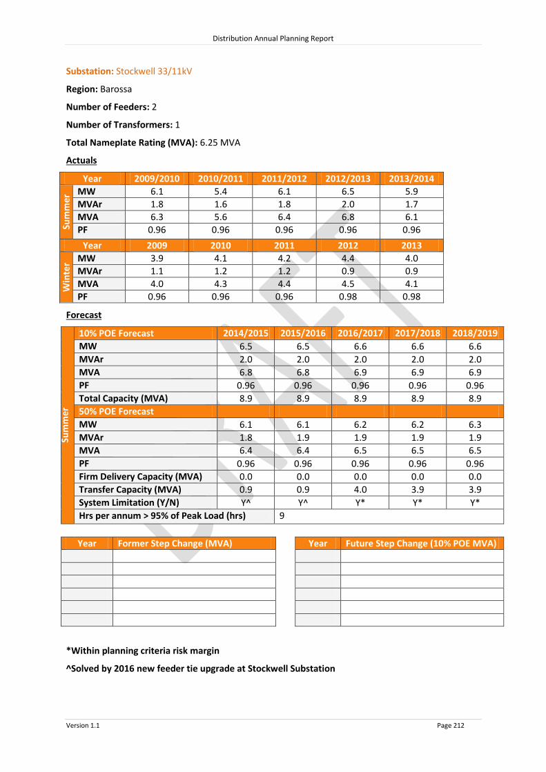
Distribution Annual Planning Report
Version 1.1 Page 212
Substation: Stockwell 33/11kV
Region: Barossa
Number of Feeders: 2
Number of Transformers: 1
Total Nameplate Rating (MVA): 6.25 MVA
Actuals
Year 2009/2010 2010/2011 2011/2012 2012/2013 2013/2014
Sum
mer
MW 6.1 5.4 6.1 6.5 5.9
MVAr 1.8 1.6 1.8 2.0 1.7
MVA 6.3 5.6 6.4 6.8 6.1
PF 0.96 0.96 0.96 0.96 0.96
Year 2009 2010 2011 2012 2013
Win
ter MW 3.9 4.1 4.2 4.4 4.0
MVAr 1.1 1.2 1.2 0.9 0.9
MVA 4.0 4.3 4.4 4.5 4.1
PF 0.96 0.96 0.96 0.98 0.98
Forecast
Sum
mer
10% POE Forecast 2014/2015 2015/2016 2016/2017 2017/2018 2018/2019
MW 6.5 6.5 6.6 6.6 6.6
MVAr 2.0 2.0 2.0 2.0 2.0
MVA 6.8 6.8 6.9 6.9 6.9
PF 0.96 0.96 0.96 0.96 0.96
Total Capacity (MVA) 8.9 8.9 8.9 8.9 8.9
50% POE Forecast
MW 6.1 6.1 6.2 6.2 6.3
MVAr 1.8 1.9 1.9 1.9 1.9
MVA 6.4
6.4
6.5
6.5
6.5 PF 0.96 0.96 0.96 0.96 0.96
Firm Delivery Capacity (MVA) 0.0 0.0 0.0 0.0 0.0
Transfer Capacity (MVA) 0.9
0.9
4.0
3.9
3.9 System Limitation (Y/N) Y^ Y^ Y* Y* Y*
Hrs per annum > 95% of Peak Load (hrs) 9
Year Former Step Change (MVA) Year Future Step Change (10% POE MVA)
*Within planning criteria risk margin
^Solved by 2016 new feeder tie upgrade at Stockwell Substation
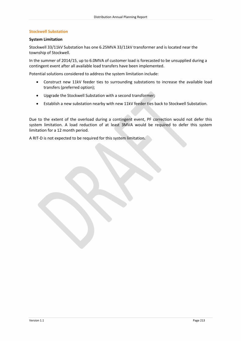
Distribution Annual Planning Report
Version 1.1 Page 213
Stockwell Substation
System Limitation
Stockwell 33/11kV Substation has one 6.25MVA 33/11kV transformer and is located near the township of Stockwell.
In the summer of 2014/15, up to 6.0MVA of customer load is forecasted to be unsupplied during a contingent event after all available load transfers have been implemented.
Potential solutions considered to address the system limitation include:
Construct new 11kV feeder ties to surrounding substations to increase the available load transfers (preferred option);
Upgrade the Stockwell Substation with a second transformer;
Establish a new substation nearby with new 11kV feeder ties back to Stockwell Substation.
Due to the extent of the overload during a contingent event, PF correction would not defer this system limitation. A load reduction of at least 3MVA would be required to defer this system limitation for a 12 month period.
A RIT-D is not expected to be required for this system limitation.

Distribution Annual Planning Report
Version 1.1 Page 214
Substation: Williamstown South 33/11kV
Region: Barossa
Number of Feeders: 1
Number of Transformers: 1
Total Nameplate Rating (MVA): 3.8 MVA
Actuals
Year 2009/2010 2010/2011 2011/2012 2012/2013 2013/2014
Sum
mer
MW N/A N/A N/A N/A N/A
MVAr N/A N/A N/A N/A N/A
MVA N/A N/A N/A N/A N/A
PF N/A N/A N/A N/A N/A
Year 2009 2010 2011 2012 2013
Win
ter MW N/A N/A N/A N/A N/A
MVAr N/A N/A N/A N/A N/A
MVA N/A N/A N/A N/A N/A
PF N/A N/A N/A N/A N/A
Forecast
Sum
mer
10% POE Forecast 2014/2015 2015/2016 2016/2017 2017/2018 2018/2019
MW 1.9 1.9 1.9 1.9 1.9
MVAr 0.5 0.5 0.5 0.5 0.5
MVA 2.0 2.0 2.0 2.0 2.0
PF 0.97 0.97 0.97 0.97 0.97
Total Capacity (MVA) 4.3 4.3 4.3 4.3 4.3
50% POE Forecast
MW 1.8 1.8 1.8 1.8 1.8
MVAr 0.5 0.5 0.5 0.5 0.5
MVA 1.9 1.9 1.9 1.9 1.9
PF 0.97 0.97 0.97 0.97 0.97
Firm Delivery Capacity (MVA) 0.0 0.0 0.0 0.0 0.0
Transfer Capacity (MVA) 2.0
2.0
2.0
2.0
2.0 System Limitation (Y/N) N N N N N
Hrs per annum > 95% of Peak Load (hrs) 6
Year Former Step Change (MVA) Year Future Step Change (10% POE MVA)
2014/15 +2MVA from Williamstown

Distribution Annual Planning Report
Version 1.1 Page 215
8.10.3 Barossa Non SCADA substations 10% POE Forecast
2014/2015 2015/2016 2016/2017 2017/2018 2018/2019
Substation No of
TFs
TF Nameplate
Rating (MVA)
Total Capacity (MVA)
10% POE Forecast (MVA)
10% POE Forecast (MVA)
10% POE Forecast (MVA)
10% POE Forecast (MVA)
10% POE Forecast (MVA)
Lyndoch South 1 0.5 0.7 0.5 0.5 0.5 0.5 0.5
Williamstown 1 2.5 3.0 1.2 1.2 1.2 1.3 1.3
System Limitations: Nil

Distribution Annual Planning Report
Version 1.1 Page 216
8.10.4 Barossa 33kV Sub-transmission Lines
Line Name - From
To Total
Capacity^ (MVA)
Forecast 2014/2015
MVA
Forecast 2015/2016
MVA
Forecast 2016/2017
MVA
Forecast 2017/2018
MVA
Forecast 2018/2019
MVA
1 2 3 4 5
33kV lines ex Dorrien
Dorrien Nuriootpa 20.3 18.5 18.5 18.5 18.5 18.5
Nuriootpa Stockwell 15.5 6.8 6.8 6.8 6.8 6.8
Dorrien Angaston No1 27.7 10.0 9.9 9.7 9.6 9.5
Dorrien No 2 Angaston No2 27.7 10.0 9.9 9.7 9.6 9.5
Dorrien Barossa South Tee 24.6 18.2 18.3 18.4 18.5 18.6
Barossa South Tee Barossa South 24.6 7.4 7.4 7.4 7.4 7.4
Barossa South Tee Lyndoch Tee 24.6 10.8 10.9 11.0 11.1 11.2
Lyndoch Tee Sandy Creek 3.9 1.7 1.8 1.9 2.0 2.0
Sandy Creek Evanston Tee 3.9 0.8 0.9 0.9 0.9 0.9
Lyndoch Tee Lyndoch 15 9.1 9.1 9.1 9.1 9.1
Lyndoch Williamstown 8.1 5.4 5.4 5.4 5.4 5.3
Williamstown A4892 6.2 0.1 0.1 0.1 0.1 0.1
^ The published rating is based on a thermal limit or a limit required to maintain adequate clearances and does not take into account voltage limitations on the network which may further reduce the published rating.

Distribution Annual Planning Report
Version 1.1 Page 217
8.11 Eastern Hills Regional Development Plan
The Eastern Hills The SA Power Networks’ Eastern Hills Region includes the region from Milang extending north to Williamstown, west to Crafers, and east to Nairne. There are three main connection systems in the Eastern Hills, being Mount Barker, Mount Barker South and Angas Creek, and a minor connection point at Kanmantoo Mine. SA Power Networks’ Distribution Network Electricity is supplied to the various towns and localities throughout the Eastern Hills via Zone Substations. These Zone Substations are operated at either 66,000 Volts stepped down to 11,000 Volts or 33,000 Volts stepped down to 11,000 Volts. Customers are supplied from SA Power Networks distribution system via 11kV and 19kV primary distribution feeders which are connected to Zone Substations. These feeders are extended and upgraded as required to meet customer demand and customer connection requests. Large customer projects may require a distribution substation upgrade as well as feeder modifications, therefore SA Power Networks should be notified as early as possible during the planning stages of a project so that customer connection requirements can be met. There are no system limitations forecast for the primary distribution feeders under normal conditions in the Eastern Hills Region in the next two years.
8.11.1 Eastern Hills SCADA Substations
Source Connection Point Associated SCADA Substations
Angas Creek Birdwood Forreston
Hermitage
Houghton
Kersbrook Lobethal Mount Pleasant
Mount Barker / Mount Barker South Aldgate
Balhannah 33kV
Hahndorf
Meadows
Mt Barker 11kV
Mylor
Nairne
Stirling East
Strathalbyn Uraidla 11kV
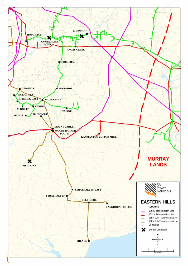
LANGHORNE CREEK
MEADOWS
STRATHALBYN
ALDGATE
STIRLING EASTPICCADILLY
URAIDLA
HAHNDORF
VERDUN
HOUGHTON
BALHANNAH
MOUNT BARKERMOUNT BARKER SOUTH
NAIRNE
WOODSIDE
LOBETHAL
MILANG
BELVIDERE
STRATHALBYN EAST
KANMANTOO COPPER MINE
ANGAS CREEK
BIRDWOOD
MYLOR
GUMERACHA WEIR
EASTERN HILLSLegend
275kV Transmission Line132kV Transmission Line66kV Sub Transmission Line33kV Sub Transmission LineSubstation
System Limitation.
0 2 4 6 8 10
Kilometres
MURRAYLANDS

Distribution Annual Planning Report
Version 1.1 Page 219
Substation: Angas Creek 132/33kV
Region: Eastern Hills
(ETC) Transmission Category: 4
Number of Transformers: 2
Total Nameplate Rating (MVA): 50 MVA
Actuals
Year 2009/2010 2010/2011 2011/2012 2012/2013 2013/2014
Sum
mer
MW 20.3 18.5 16.0 17.8 18.8
MVAr 7.8 5.6 4.9 5.2 5.2
MVA 21.7 19.3 16.7 18.6 19.5
PF 0.93 0.96 0.96 0.96 0.96
Year 2009 2010 2011 2012 2013
Win
ter MW 14.8 16.4 15.4 15.1 14.9
MVAr 2.1 2.8 0.1 0.5 0.5
MVA 15.0 16.6 15.4 15.1 14.9
PF 0.99 0.99 1.00 1.00 1.00
Forecast
Sum
mer
10% POE Forecast 2014/2015 2015/2016 2016/2017 2017/2018 2018/2019
MW 18.3 18.2 18.2 18.2 18.1
MVAr 5.4 5.4 5.4 5.3 5.3
MVA 19.1 19.0 19.0 18.9 18.9
PF 0.96 0.96 0.96 0.96 0.96
Firm Delivery Capacity (MVA) 31.5 31.5 31.5 31.5 31.5
System Limitation (Y/N) N N N N N
Hrs per annum > 95% of Peak Load (hrs) 2
Year Former Step Change (MVA) Year Future Step Change (10% POE MVA)

Distribution Annual Planning Report
Version 1.1 Page 220
Substation: Kanmantoo 132/11kV
Region: Eastern Hills
(ETC) Transmission Category: 1
Number of Transformers: 1
Total Nameplate Rating (MVA): 3 MVA
Actuals
Year 2009/2010 2010/2011 2011/2012 2012/2013 2013/2014
Sum
mer
MW 1.7 1.6 1.4 1.4 1.7
MVAr 0.6 0.5 0.5 0.3 0.4
MVA 1.8 1.7 1.5 1.4 1.7
PF 0.94 0.95 0.94 0.97 0.97
Year 2009 2010 2011 2012 2013
Win
ter MW 1.4 1.4 1.4 1.3 1.5
MVAr 0.3 0.3 0.3 0.4 0.3
MVA 1.4 1.4 1.4 1.4 1.5
PF 0.98 0.98 0.98 0.97 0.99
Forecast
Sum
mer
10% POE Forecast 2014/2015 2015/2016 2016/2017 2017/2018 2018/2019
MW 1.5 1.6 1.6 1.6 1.6
MVAr 0.5 0.5 0.5 0.5 0.5
MVA 1.6 1.6 1.6 1.6 1.6
PF 0.95 0.95 0.95 0.95 0.95
Total Capacity (MVA) 3.0 3.0 3.0 3.0 3.0
System Limitation (Y/N) N N N N N
Hrs per annum > 95% of Peak Load (hrs) 2
Year Former Step Change (MVA) Year Future Step Change (10% POE MVA)

Distribution Annual Planning Report
Version 1.1 Page 221
Substation: Mount Barker/Mount Barker South 275/66kV
Region: Eastern Hills
(ETC) Transmission Category: 4G
Number of Transformers: 3
Total Nameplate Rating (MVA): 345 MVA
Actuals
Year 2009/2010 2010/2011 2011/2012 2012/2013 2013/2014
Sum
mer
MW 101.6 96.5 78.7 89.2 96.3
MVAr 40.1 33.9 30.0 32.4 33.1
MVA 109.2 102.3 84.2 94.9 101.9
PF 0.93 0.93 0.93 0.94 0.95
Year 2009 2010 2011 2012 2013
Win
ter MW 79.0 76.8 84.4 83.9 85.0
MVAr 14.1 12.8 17.3 15.4 17.8
MVA 80.3 77.9 86.2 85.3 86.8
PF 0.98 0.99 0.98 0.98 0.98
Forecast
Sum
mer
10% POE Forecast 2014/2015 2015/2016 2016/2017 2017/2018 2018/2019
MW 97.8 99.4 101.0 102.5 103.9
MVAr 27.0 27.4 27.9 28.3 28.7
MVA 101.5 103.1 104.8 106.3 107.8
PF 0.96 0.96 0.96 0.96 0.96
Firm Delivery Capacity (MVA) 149.0 149.0 149.0 149.0 149.0
System Limitation (Y/N) N N N N N
Hrs per annum > 95% of Peak Load (hrs) 6
Year Former Step Change (MVA) Year Future Step Change (10% POE MVA)
2011/12 30.0MVAr Capacitor Bank installed at Mount Barker South

Distribution Annual Planning Report
Version 1.1 Page 222
Substation: Aldgate 33/11kV
Region: Eastern Hills
Number of Feeders: 3
Number of Transformers: 2
Total Nameplate Rating (MVA): 10 MVA
Actuals
Year 2009/2010 2010/2011 2011/2012 2012/2013 2013/2014
Sum
mer
MW 9.3 10.2 9.2 9.1 7.0
MVAr 2.8 2.8 1.9 2.0 1.2
MVA 9.7 10.6 9.4 9.3 7.1
PF 0.96 0.97 0.98 0.98 0.99
Year 2009 2010 2011 2012 2013
Win
ter MW 10.5 11.0 10.6 11.3 10.4
MVAr 0.6 1.6 0.5 0.5 0.3
MVA 10.5 11.1 10.6 11.3 10.4
PF 1.00 0.99 1.00 1.00 1.00
Forecast
Sum
mer
10% POE Forecast 2014/2015 2015/2016 2016/2017 2017/2018 2018/2019
MW 7.1 7.2 7.3 7.4 7.5
MVAr 1.2 1.2 1.2 1.2 1.3
MVA 7.2 7.3 7.4 7.5 7.6
PF 0.99 0.99 0.99 0.99 0.99
Total Capacity (MVA) 12.6 12.6 12.6 12.6 12.6
50% POE Forecast
MW 7.2 7.3 7.4 7.5 7.6
MVAr 1.2 1.2 1.2 1.3 1.3
MVA 7.3 7.4 7.5 7.6 7.7
PF 0.99 0.99 0.99 0.99 0.99
Firm Delivery Capacity (MVA) 7.1 7.1 7.1 7.1 7.1
Transfer Capacity (MVA) 5.2
5.1
5.0
5.0
4.9 System Limitation (Y/N) N N N N N
Hrs per annum > 95% of Peak Load (hrs) 5
Year Former Step Change (MVA) Year Future Step Change (10% POE MVA)
2009/10 +0.7MVA from Stirling East
2011/12 +0.3MVA Customer load increase
2013/14 -3.6MVA to Stirling East
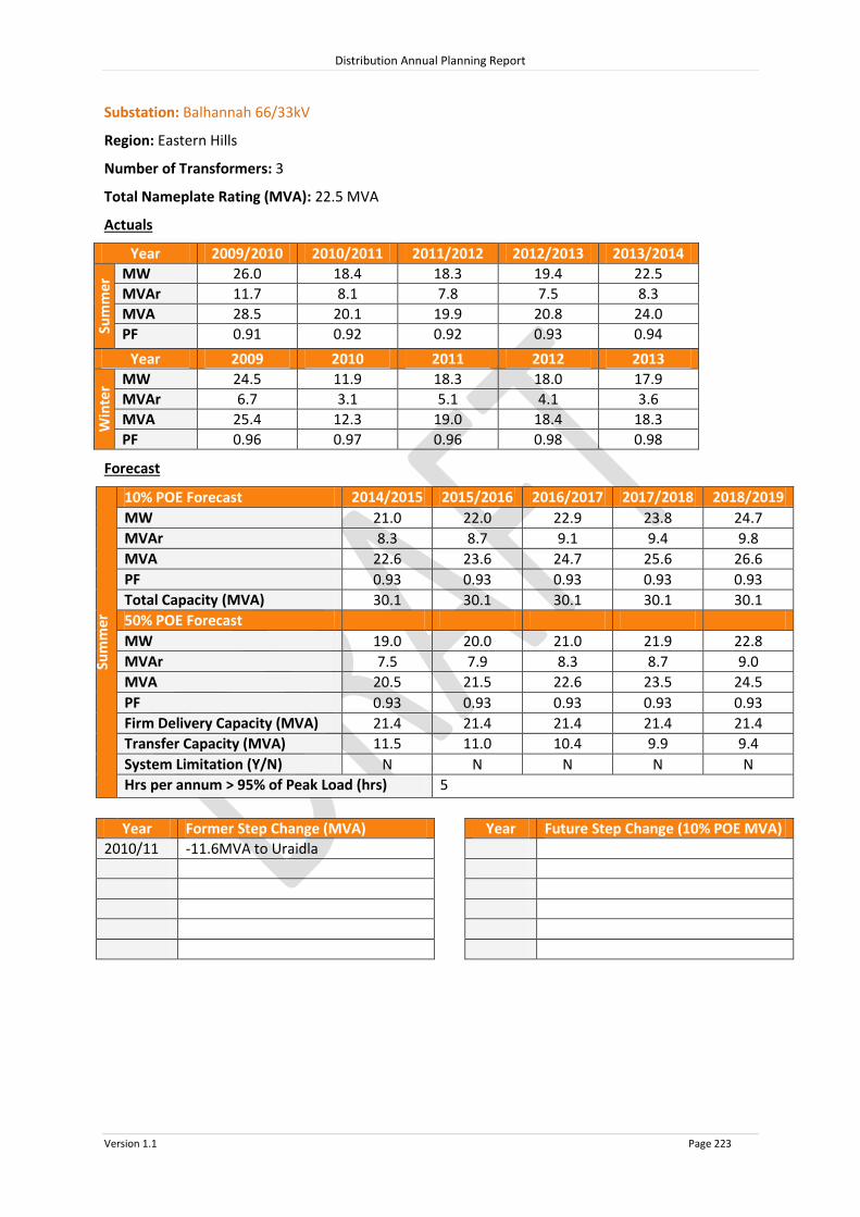
Distribution Annual Planning Report
Version 1.1 Page 223
Substation: Balhannah 66/33kV
Region: Eastern Hills
Number of Transformers: 3
Total Nameplate Rating (MVA): 22.5 MVA
Actuals
Year 2009/2010 2010/2011 2011/2012 2012/2013 2013/2014
Sum
mer
MW 26.0 18.4 18.3 19.4 22.5
MVAr 11.7 8.1 7.8 7.5 8.3
MVA 28.5 20.1 19.9 20.8 24.0
PF 0.91 0.92 0.92 0.93 0.94
Year 2009 2010 2011 2012 2013
Win
ter MW 24.5 11.9 18.3 18.0 17.9
MVAr 6.7 3.1 5.1 4.1 3.6
MVA 25.4 12.3 19.0 18.4 18.3
PF 0.96 0.97 0.96 0.98 0.98
Forecast
Sum
mer
10% POE Forecast 2014/2015 2015/2016 2016/2017 2017/2018 2018/2019
MW 21.0 22.0 22.9 23.8 24.7
MVAr 8.3 8.7 9.1 9.4 9.8
MVA 22.6 23.6 24.7 25.6 26.6
PF 0.93 0.93 0.93 0.93 0.93
Total Capacity (MVA) 30.1 30.1 30.1 30.1 30.1
50% POE Forecast
MW 19.0 20.0 21.0 21.9 22.8
MVAr 7.5 7.9 8.3 8.7 9.0
MVA 20.5
21.5
22.6
23.5
24.5 PF 0.93 0.93 0.93 0.93 0.93
Firm Delivery Capacity (MVA) 21.4 21.4 21.4 21.4 21.4
Transfer Capacity (MVA) 11.5
11.0
10.4
9.9
9.4 System Limitation (Y/N) N N N N N
Hrs per annum > 95% of Peak Load (hrs) 5
Year Former Step Change (MVA) Year Future Step Change (10% POE MVA)
2010/11 -11.6MVA to Uraidla

Distribution Annual Planning Report
Version 1.1 Page 224
Substation: Birdwood 33/11kV
Region: Eastern Hills
Number of Feeders: 2
Number of Transformers: 3
Total Nameplate Rating (MVA): 3 MVA
Actuals
Year 2009/2010 2010/2011 2011/2012 2012/2013 2013/2014
Sum
mer
MW N/A N/A N/A N/A N/A
MVAr N/A N/A N/A N/A N/A
MVA N/A N/A N/A N/A N/A
PF N/A N/A N/A N/A N/A
Year 2009 2010 2011 2012 2013
Win
ter MW N/A N/A N/A N/A N/A
MVAr N/A N/A N/A N/A N/A
MVA N/A N/A N/A N/A N/A
PF N/A N/A N/A N/A N/A
Forecast
Sum
mer
10% POE Forecast 2014/2015 2015/2016 2016/2017 2017/2018 2018/2019
MW 2.3 2.3 2.2 2.2 2.2
MVAr 0.7 0.7 0.7 0.6 0.6
MVA 2.4 2.4 2.3 2.3 2.3
PF 0.96 0.96 0.96 0.96 0.96
Total Capacity (MVA) 3.9 3.9 3.9 3.9 3.9
50% POE Forecast
MW 2.1 2.1 2.0 2.0 2.0
MVAr 0.6 0.6 0.6 0.6 0.6
MVA 2.2
2.1
2.1
2.1
2.1 PF 0.96 0.96 0.96 0.96 0.96
Firm Delivery Capacity (MVA) 3.0 3.0 3.0 3.0 3.0
Transfer Capacity (MVA) 0.7
0.8
0.8
0.8
0.8 System Limitation (Y/N) N N N N N
Hrs per annum > 95% of Peak Load (hrs) 5
Year Former Step Change (MVA) Year Future Step Change (10% POE MVA)

Distribution Annual Planning Report
Version 1.1 Page 225
Substation: Forreston 33/11kV
Region: Eastern Hills
Number of Feeders: 1
Number of Transformers: 1
Total Nameplate Rating (MVA): 1 MVA
Actuals
Year 2009/2010 2010/2011 2011/2012 2012/2013 2013/2014
Sum
mer
MW N/A N/A N/A N/A N/A
MVAr N/A N/A N/A N/A N/A
MVA N/A N/A N/A N/A N/A
PF N/A N/A N/A N/A N/A
Year 2009 2010 2011 2012 2013
Win
ter MW N/A N/A N/A N/A N/A
MVAr N/A N/A N/A N/A N/A
MVA N/A N/A N/A N/A N/A
PF N/A N/A N/A N/A N/A
Forecast
Sum
mer
10% POE Forecast 2014/2015 2015/2016 2016/2017 2017/2018 2018/2019
MW 1.0 1.0 0.9 0.9 0.9
MVAr 0.3 0.3 0.3 0.3 0.3
MVA 1.0 1.0 1.0 1.0 1.0
PF 0.96 0.96 0.96 0.96 0.96
Total Capacity (MVA) 1.3 1.3 1.3 1.3 1.3
50% POE Forecast
MW 0.9 0.9 0.9 0.9 0.8
MVAr 0.3 0.3 0.2 0.2 0.2
MVA 0.9
0.9
0.9
0.9
0.9 PF 0.96 0.96 0.96 0.96 0.96
Firm Delivery Capacity (MVA) 0.0 0.0 0.0 0.0 0.0
Transfer Capacity (MVA) 0.0
0.0
0.0
0.0
0.0 System Limitation (Y/N) Y* Y* Y* Y* Y*
Hrs per annum > 95% of Peak Load (hrs) 5
Year Former Step Change (MVA) Year Future Step Change (10% POE MVA)
*Within planning criteria risk margin

Distribution Annual Planning Report
Version 1.1 Page 226
Substation: Hahndorf 66/11kV
Region: Eastern Hills
Number of Feeders: 2
Number of Transformers: 1
Total Nameplate Rating (MVA): 5 MVA
Actuals
Year 2009/2010 2010/2011 2011/2012 2012/2013 2013/2014
Sum
mer
MW 4.6 5.1 4.3 4.5 4.7
MVAr 2.1 2.2 1.7 1.8 1.5
MVA 5.0 5.6 4.6 4.8 5.0
PF 0.91 0.92 0.93 0.93 0.95
Year 2009 2010 2011 2012 2013
Win
ter MW 3.8 4.1 4.2 4.5 4.2
MVAr 1.2 1.2 1.4 1.2 1.2
MVA 4.0 4.3 4.4 4.6 4.4
PF 0.95 0.96 0.95 0.97 0.96
Forecast
Sum
mer
10% POE Forecast 2014/2015 2015/2016 2016/2017 2017/2018 2018/2019
MW 4.5 4.5 4.4 4.3 4.3
MVAr 1.7 1.7 1.6 1.6 1.6
MVA 4.8 4.8 4.7 4.6 4.6
PF 0.94 0.94 0.94 0.94 0.94
Total Capacity (MVA) 6.8 6.8 6.8 6.8 6.8
50% POE Forecast
MW 4.1 4.0 4.0 4.0 3.9
MVAr 1.5 1.5 1.5 1.5 1.5
MVA 4.3
4.3
4.3
4.2
4.2 PF 0.94 0.94 0.94 0.94 0.94
Firm Delivery Capacity (MVA) 0.0 0.0 0.0 0.0 0.0
Transfer Capacity (MVA) 6.2
6.2
6.2
6.2
6.3 System Limitation (Y/N) N N N N N
Hrs per annum > 95% of Peak Load (hrs) 7
Year Former Step Change (MVA) Year Future Step Change (10% POE MVA)
2010/11 +0.4MVA from Verdun

Distribution Annual Planning Report
Version 1.1 Page 227
Substation: Hermitage 33/11kV
Region: Eastern Hills
Number of Feeders: 1
Number of Transformers: 1
Total Nameplate Rating (MVA): 0.5 MVA
Actuals
Year 2009/2010 2010/2011 2011/2012 2012/2013 2013/2014
Sum
mer
MW N/A N/A N/A N/A N/A
MVAr N/A N/A N/A N/A N/A
MVA N/A N/A N/A N/A N/A
PF N/A N/A N/A N/A N/A
Year 2009 2010 2011 2012 2013
Win
ter MW N/A N/A N/A N/A N/A
MVAr N/A N/A N/A N/A N/A
MVA N/A N/A N/A N/A N/A
PF N/A N/A N/A N/A N/A
Forecast
Sum
mer
10% POE Forecast 2014/2015 2015/2016 2016/2017 2017/2018 2018/2019
MW 0.2 0.2 0.2 0.2 0.2
MVAr 0.1 0.1 0.1 0.1 0.1
MVA 0.2 0.2 0.2 0.2 0.2
PF 0.96 0.96 0.96 0.96 0.96
Total Capacity (MVA) 0.7 0.7 0.7 0.7 0.7
50% POE Forecast
MW 0.2
0.2
0.2
0.2
0.2 MVAr 0.1
0.1
0.1
0.1
0.1
MVA 0.2
0.2
0.2
0.2
0.2 PF 0.96
0.96
0.96
0.96
0.96
Firm Delivery Capacity (MVA) 0.0 0.0 0.0 0.0 0.0
Transfer Capacity (MVA) 0.0
0.0
0.0
0.0
0.0 System Limitation (Y/N) Y* Y* Y* Y* Y*
Hrs per annum > 95% of Peak Load (hrs) 5
Year Former Step Change (MVA) Year Future Step Change (10% POE MVA)
*Within planning criteria risk margin

Distribution Annual Planning Report
Version 1.1 Page 228
Substation: Houghton 33/7.6kV
Region: Eastern Hills
Number of Feeders: 2
Number of Transformers: 1
Total Nameplate Rating (MVA): 3 MVA
Actuals
Year 2009/2010 2010/2011 2011/2012 2012/2013 2013/2014
Sum
mer
MW N/A N/A 2.0 2.1 1.8
MVAr N/A N/A 1.0 0.8 0.9
MVA N/A N/A 2.3 2.2 2.0
PF N/A N/A 0.88 0.93 0.90
Year 2009 2010 2011 2012 2013
Win
ter MW N/A N/A N/A 1.7 1.7
MVAr N/A N/A N/A 0.7 0.4
MVA N/A N/A N/A 1.8 1.8
PF N/A N/A N/A 0.93 0.96
Forecast
Sum
mer
10% POE Forecast 2014/2015 2015/2016 2016/2017 2017/2018 2018/2019
MW 3.0 3.0 3.1 3.2 3.2
MVAr 0.9 0.9 0.9 0.9 0.9
MVA 3.1 3.2 3.2 3.3 3.3
PF 0.96 0.96 0.96 0.96 0.96
Total Capacity (MVA) 3.6 3.6 3.6 3.6 3.6
50% POE Forecast
MW 2.7 2.7 2.8 2.8 2.9
MVAr 0.8 0.8 0.8 0.8 0.8
MVA 2.8
2.8
2.9
3.0
3.0 PF 0.96 0.96 0.96 0.96 0.96
Firm Delivery Capacity (MVA) 0.0 0.0 0.0 0.0 0.0
Transfer Capacity (MVA) 0.0
0.0
0.0
0.0
0.0 System Limitation (Y/N) Y* Y* Y* Y* Y*
Hrs per annum > 95% of Peak Load (hrs) 5
Year Former Step Change (MVA) Year Future Step Change (10% POE MVA)
*Within planning criteria risk margin

Distribution Annual Planning Report
Version 1.1 Page 229
Substation: Kersbrook 33/11kV
Region: Eastern Hills
Number of Feeders: 1
Number of Transformers: 1
Total Nameplate Rating (MVA): 1 MVA
Actuals
Year 2009/2010 2010/2011 2011/2012 2012/2013 2013/2014
Sum
mer
MW N/A N/A N/A N/A N/A
MVAr N/A N/A N/A N/A N/A
MVA N/A N/A N/A N/A N/A
PF N/A N/A N/A N/A N/A
Year 2009 2010 2011 2012 2013
Win
ter MW N/A N/A N/A N/A N/A
MVAr N/A N/A N/A N/A N/A
MVA N/A N/A N/A N/A N/A
PF N/A N/A N/A N/A N/A
Forecast
Sum
mer
10% POE Forecast 2014/2015 2015/2016 2016/2017 2017/2018 2018/2019
MW 0.6 0.6 0.6 0.6 0.6
MVAr 0.2 0.2 0.2 0.2 0.2
MVA 0.6 0.6 0.6 0.6 0.6
PF 0.96 0.96 0.96 0.96 0.96
Total Capacity (MVA) 1.3 1.3 1.3 1.3 1.3
50% POE Forecast
MW 0.5 0.5 0.5 0.5 0.5
MVAr 0.2 0.2 0.1 0.1 0.1
MVA 0.5
0.5
0.5
0.5
0.5 PF 0.96 0.96 0.96 0.96 0.96
Firm Delivery Capacity (MVA) 0.0 0.0 0.0 0.0 0.0
Transfer Capacity (MVA) 0.1
0.1 0.1 0.1 0.1
System Limitation (Y/N) Y* Y* Y* Y* Y*
Hrs per annum > 95% of Peak Load (hrs) 5
Year Former Step Change (MVA) Year Future Step Change (10% POE MVA)
*Within planning criteria risk margin

Distribution Annual Planning Report
Version 1.1 Page 230
Substation: Lobethal 33/11kV
Region: Eastern Hills
Number of Feeders: 3
Number of Transformers: 2
Total Nameplate Rating (MVA): 10 MVA
Actuals
Year 2009/2010 2010/2011 2011/2012 2012/2013 2013/2014
Sum
mer
MW 8.3 8.2 6.1 6.3 6.7
MVAr 2.8 2.1 1.8 2.2 1.3
MVA 8.8 8.5 6.3 6.7 6.8
PF 0.95 0.97 0.96 0.94 0.98
Year 2009 2010 2011 2012 2013
Win
ter MW 5.4 6.6 5.5 5.5 5.3
MVAr 0.4 0.2 0.7 0.5 0.2
MVA 5.4 6.6 5.5 5.5 5.3
PF 1.00 1.00 0.99 1.00 1.00
Forecast
Sum
mer
10% POE Forecast 2014/2015 2015/2016 2016/2017 2017/2018 2018/2019
MW 6.7 6.6 6.4 6.3 6.2
MVAr 1.7 1.7 1.6 1.6 1.6
MVA 6.9 6.8 6.6 6.5 6.4
PF 0.97 0.97 0.97 0.97 0.97
Total Capacity (MVA) 12.8 12.8 12.8 12.8 12.8
50% POE Forecast
MW 6.1 6.0 5.9 5.8 5.7
MVAr 1.6 1.5 1.5 1.5 1.4
MVA 6.3
6.2
6.1
6.0
5.9 PF 0.97 0.97 0.97 0.97 0.97
Firm Delivery Capacity (MVA) 6.9 6.9 6.9 6.9 6.9
Transfer Capacity (MVA) 1.8
1.8
1.8
1.9
1.9 System Limitation (Y/N) N N N N N
Hrs per annum > 95% of Peak Load (hrs) 9
Year Former Step Change (MVA) Year Future Step Change (10% POE MVA)
2009/10 +1.2MVA from Woodside
2011/12 -1.2MVA to Woodside
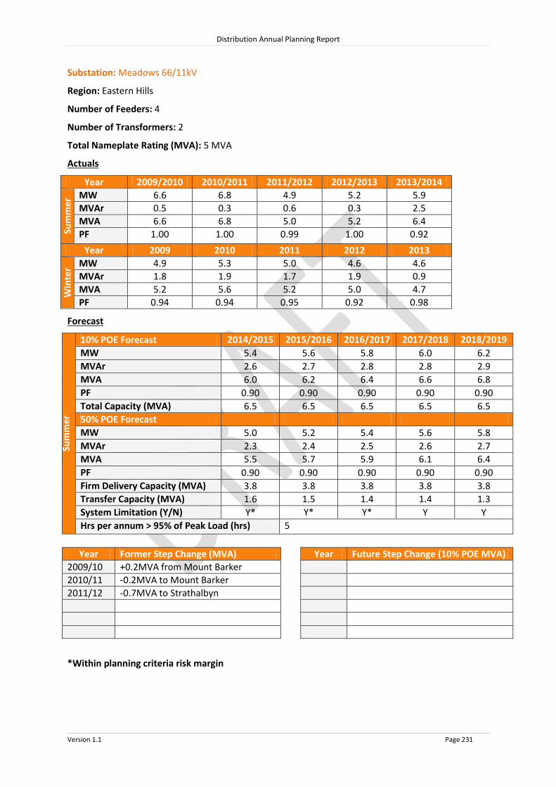
Distribution Annual Planning Report
Version 1.1 Page 231
Substation: Meadows 66/11kV
Region: Eastern Hills
Number of Feeders: 4
Number of Transformers: 2
Total Nameplate Rating (MVA): 5 MVA
Actuals
Year 2009/2010 2010/2011 2011/2012 2012/2013 2013/2014
Sum
mer
MW 6.6 6.8 4.9 5.2 5.9
MVAr 0.5 0.3 0.6 0.3 2.5
MVA 6.6 6.8 5.0 5.2 6.4
PF 1.00 1.00 0.99 1.00 0.92
Year 2009 2010 2011 2012 2013
Win
ter MW 4.9 5.3 5.0 4.6 4.6
MVAr 1.8 1.9 1.7 1.9 0.9
MVA 5.2 5.6 5.2 5.0 4.7
PF 0.94 0.94 0.95 0.92 0.98
Forecast
Sum
mer
10% POE Forecast 2014/2015 2015/2016 2016/2017 2017/2018 2018/2019
MW 5.4 5.6 5.8 6.0 6.2
MVAr 2.6 2.7 2.8 2.8 2.9
MVA 6.0 6.2 6.4 6.6 6.8
PF 0.90 0.90 0.90 0.90 0.90
Total Capacity (MVA) 6.5 6.5 6.5 6.5 6.5
50% POE Forecast
MW 5.0 5.2 5.4 5.6 5.8
MVAr 2.3 2.4 2.5 2.6 2.7
MVA 5.5
5.7
5.9
6.1
6.4 PF 0.90 0.90 0.90 0.90 0.90
Firm Delivery Capacity (MVA) 3.8 3.8 3.8 3.8 3.8
Transfer Capacity (MVA) 1.6
1.5
1.4
1.4
1.3 System Limitation (Y/N) Y* Y* Y* Y Y
Hrs per annum > 95% of Peak Load (hrs) 5
Year Former Step Change (MVA) Year Future Step Change (10% POE MVA)
2009/10 +0.2MVA from Mount Barker
2010/11 -0.2MVA to Mount Barker
2011/12 -0.7MVA to Strathalbyn
*Within planning criteria risk margin

Distribution Annual Planning Report
Version 1.1 Page 232
Substation: Mount Barker 66/11kV
Region: Eastern Hills
Number of Feeders: 6
Number of Transformers: 2
Total Nameplate Rating (MVA): 64 MVA
Actuals
Year 2009/2010 2010/2011 2011/2012 2012/2013 2013/2014
Sum
mer
MW 23.5 24.5 18.1 19.3 21.9
MVAr 1.8 1.8 2.6 2.6 0.2
MVA 23.6 24.6 18.3 19.5 21.9
PF 1.00 1.00 0.99 0.99 1.00
Year 2009 2010 2011 2012 2013
Win
ter MW 20.9 22.5 19.4 19.0 18.8
MVAr 2.0 0.9 0.6 0.5 0.0
MVA 21.0 22.5 19.4 19.0 18.8
PF 1.00 1.00 1.00 1.00 1.00
Forecast
Sum
mer
10% POE Forecast 2014/2015 2015/2016 2016/2017 2017/2018 2018/2019
MW 21.4 22.3 23.3 24.1 25.0
MVAr 2.4 2.5 2.6 2.7 2.8
MVA 21.6 22.5 23.4 24.3 25.2
PF 0.99 0.99 0.99 0.99 0.99
Total Capacity (MVA) 72.4 72.4 72.4 72.4 72.4
50% POE Forecast
MW 19.0 19.7 20.5 21.3 22.0
MVAr 2.1 2.2 2.3 2.4 2.5
MVA 19.1 19.9 20.7 21.4 22.2
PF 0.99 0.99 0.99 0.99 0.99
Firm Delivery Capacity (MVA) 38.1 38.1 38.1 38.1 38.1
Transfer Capacity (MVA) 1.5
1.4
1.4
1.3
1.3 System Limitation (Y/N) N N N N N
Hrs per annum > 95% of Peak Load (hrs) 7
Year Former Step Change (MVA) Year Future Step Change (10% POE MVA)
2009/10 -0.2MVA to Meadows
2010/11 +0.2MVA from Meadows
-1.9MVA to Nairne

Distribution Annual Planning Report
Version 1.1 Page 233
Substation: Mount Pleasant 33/11kV
Region: Eastern Hills
Number of Feeders: 1
Number of Transformers: 1
Total Nameplate Rating (MVA): 2 MVA
Actuals
Year 2009/2010 2010/2011 2011/2012 2012/2013 2013/2014
Sum
mer
MW N/A N/A N/A N/A N/A
MVAr N/A N/A N/A N/A N/A
MVA N/A N/A N/A N/A N/A
PF N/A N/A N/A N/A N/A
Year 2009 2010 2011 2012 2013
Win
ter MW N/A N/A N/A N/A N/A
MVAr N/A N/A N/A N/A N/A
MVA N/A N/A N/A N/A N/A
PF N/A N/A N/A N/A N/A
Forecast
Sum
mer
10% POE Forecast 2014/2015 2015/2016 2016/2017 2017/2018 2018/2019
MW 1.6 1.6 1.6 1.5 1.5
MVAr 0.5 0.5 0.5 0.5 0.4
MVA 1.7 1.7 1.6 1.6 1.6
PF 0.96 0.96 0.96 0.96 0.96
Total Capacity (MVA) 2.6 2.6 2.6 2.6 2.6
50% POE Forecast
MW 1.4 1.4 1.4 1.4 1.4
MVAr 0.4 0.4 0.4 0.4 0.4
MVA 1.5
1.5
1.5
1.4
1.4 PF 0.96 0.96 0.96 0.96 0.96
Firm Delivery Capacity (MVA) 0.0 0.0 0.0 0.0 0.0
Transfer Capacity (MVA) 1.7
1.7
1.7
1.7
1.8 System Limitation (Y/N) N N N N N
Hrs per annum > 95% of Peak Load (hrs) 5
Year Former Step Change (MVA) Year Future Step Change (10% POE MVA)
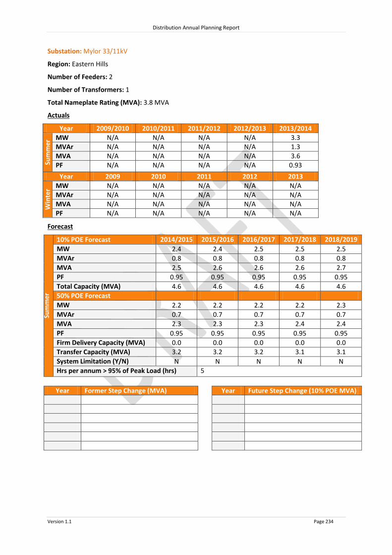
Distribution Annual Planning Report
Version 1.1 Page 234
Substation: Mylor 33/11kV
Region: Eastern Hills
Number of Feeders: 2
Number of Transformers: 1
Total Nameplate Rating (MVA): 3.8 MVA
Actuals
Year 2009/2010 2010/2011 2011/2012 2012/2013 2013/2014
Sum
mer
MW N/A N/A N/A N/A 3.3
MVAr N/A N/A N/A N/A 1.3
MVA N/A N/A N/A N/A 3.6
PF N/A N/A N/A N/A 0.93
Year 2009 2010 2011 2012 2013
Win
ter MW N/A N/A N/A N/A N/A
MVAr N/A N/A N/A N/A N/A
MVA N/A N/A N/A N/A N/A
PF N/A N/A N/A N/A N/A
Forecast
Sum
mer
10% POE Forecast 2014/2015 2015/2016 2016/2017 2017/2018 2018/2019
MW 2.4 2.4 2.5 2.5 2.5
MVAr 0.8 0.8 0.8 0.8 0.8
MVA 2.5 2.6 2.6 2.6 2.7
PF 0.95 0.95 0.95 0.95 0.95
Total Capacity (MVA) 4.6 4.6 4.6 4.6 4.6
50% POE Forecast
MW 2.2 2.2 2.2 2.2 2.3
MVAr 0.7 0.7 0.7 0.7 0.7
MVA 2.3
2.3
2.3
2.4
2.4 PF 0.95 0.95 0.95 0.95 0.95
Firm Delivery Capacity (MVA) 0.0 0.0 0.0 0.0 0.0
Transfer Capacity (MVA) 3.2
3.2
3.2
3.1
3.1 System Limitation (Y/N) N N N N N
Hrs per annum > 95% of Peak Load (hrs) 5
Year Former Step Change (MVA) Year Future Step Change (10% POE MVA)

Distribution Annual Planning Report
Version 1.1 Page 235
Substation: Nairne 33/11kV
Region: Eastern Hills
Number of Feeders: 3
Number of Transformers: 2
Total Nameplate Rating (MVA): 7.6 MVA
Actuals
Year 2009/2010 2010/2011 2011/2012 2012/2013 2013/2014
Sum
mer
MW N/A 7.2 5.9 6.4 7.2
MVAr N/A 2.2 2.1 2.1 2.3
MVA N/A 7.5 6.2 6.7 7.5
PF N/A 0.96 0.94 0.95 0.95
Year 2009 2010 2011 2012 2013
Win
ter MW N/A 3.7 6.7 6.8 7.0
MVAr N/A 0.7 0.7 1.1 0.5
MVA N/A 3.7 6.8 6.9 7.0
PF N/A 0.98 0.99 0.99 1.00
Forecast
Sum
mer
10% POE Forecast 2014/2015 2015/2016 2016/2017 2017/2018 2018/2019
MW 6.5 6.5 6.5 6.6 6.6
MVAr 2.3 2.3 2.3 2.3 2.3
MVA 6.8 6.9 6.9 6.9 7.0
PF 0.94 0.94 0.94 0.94 0.94
Total Capacity (MVA) 9.2 9.2 9.2 9.2 9.2
50% POE Forecast
MW 5.7 5.7 5.7 5.7 5.7
MVAr 2.0 2.0 2.0 2.0 2.0
MVA 6.0
6.0
6.0
6.0
6.0 PF 0.94 0.94 0.94 0.94 0.94
Firm Delivery Capacity (MVA) 4.9 4.9 4.9 4.9 4.9
Transfer Capacity (MVA) 2.2
2.2
2.2
2.2
2.2 System Limitation (Y/N) N N N N N
Hrs per annum > 95% of Peak Load (hrs) 5
Year Former Step Change (MVA) Year Future Step Change (10% POE MVA)
2010/11 +1.9MVA from Mount Barker

Distribution Annual Planning Report
Version 1.1 Page 236
Substation: Stirling East 33/11kV
Region: Eastern Hills
Number of Feeders: 3
Number of Transformers: 1
Total Nameplate Rating (MVA): 12.5 MVA
Actuals
Year 2009/2010 2010/2011 2011/2012 2012/2013 2013/2014
Sum
mer
MW N/A N/A N/A N/A N/A
MVAr N/A N/A N/A N/A N/A
MVA N/A N/A N/A N/A N/A
PF N/A N/A N/A N/A N/A
Year 2009 2010 2011 2012 2013
Win
ter MW N/A N/A N/A N/A N/A
MVAr N/A N/A N/A N/A N/A
MVA N/A N/A N/A N/A N/A
PF N/A N/A N/A N/A N/A
Forecast
Sum
mer
10% POE Forecast 2014/2015 2015/2016 2016/2017 2017/2018 2018/2019
MW 9.0 9.2 9.3 9.4 9.5
MVAr 3.0 3.0 3.0 3.1 3.1
MVA 9.5 9.6 9.8 9.9 10.0
PF 0.95 0.95 0.95 0.95 0.95
Total Capacity (MVA) 17.7 17.7 17.7 17.7 17.7
50% POE Forecast
MW 8.1 8.2 8.3 8.4 8.6
MVAr 2.7 2.7 2.7 2.8 2.8
MVA 8.6
8.7
8.8
8.9
9.0 PF 0.95 0.95 0.95 0.95 0.95
Firm Delivery Capacity (MVA) 0.0 0.0 0.0 0.0 0.0
Transfer Capacity (MVA) 8.1
8.0
7.9
7.8
7.7 System Limitation (Y/N) Y* Y* Y* Y* Y*
Hrs per annum > 95% of Peak Load (hrs) 5
Year Former Step Change (MVA) Year Future Step Change (10% POE MVA)
2009/10 -0.7MVA to Aldgate
2013/14 +3.6MVA from Aldgate
+2.1MVA from Piccadilly
*Within planning criteria risk margin

Distribution Annual Planning Report
Version 1.1 Page 237
Substation: Strathalbyn 66/11kV
Region: Eastern Hills
Number of Feeders: 3
Number of Transformers: 1
Total Nameplate Rating (MVA): 12.5 MVA
Actuals
Year 2009/2010 2010/2011 2011/2012 2012/2013 2013/2014
Sum
mer
MW 9.1 10.3 8.8 9.6 10.3
MVAr 2.4 2.8 2.3 2.2 2.3
MVA 9.4 10.6 9.1 9.8 10.5
PF 0.97 0.97 0.97 0.97 0.98
Year 2009 2010 2011 2012 2013
Win
ter MW 8.2 9.1 8.9 9.1 9.0
MVAr 0.5 0.5 0.6 0.4 0.3
MVA 8.2 9.1 8.9 9.1 9.0
PF 1.00 1.00 1.00 1.00 1.00
Forecast
Sum
mer
10% POE Forecast 2014/2015 2015/2016 2016/2017 2017/2018 2018/2019
MW 9.2 9.3 9.4 9.4 9.5
MVAr 2.1 2.1 2.2 2.2 2.2
MVA 9.5 9.6 9.6 9.7 9.7
PF 0.97 0.97 0.97 0.97 0.97
Total Capacity (MVA) 16.7 16.7 16.7 16.7 16.7
50% POE Forecast
MW 8.2 8.3 8.4 8.5 8.6
MVAr 1.9 1.9 1.9 2.0 2.0
MVA 8.4
8.5
8.6
8.7
8.8 PF 0.97 0.97 0.97 0.97 0.97
Firm Delivery Capacity (MVA) 0.0 0.0 0.0 0.0 0.0
Transfer Capacity (MVA) 11.6
11.4
11.3
11.2
11.0 System Limitation (Y/N) N N N N N
Hrs per annum > 95% of Peak Load (hrs) 5
Year Former Step Change (MVA) Year Future Step Change (10% POE MVA)
2011/12 +0.7MVA from Meadows
2012/13 -0.75MVA Customer load decrease

Distribution Annual Planning Report
Version 1.1 Page 238
Substation: Uraidla 66/33kV
Region: Eastern Hills
Number of Transformers: 1
Total Nameplate Rating (MVA): 25 MVA
Actuals
Year 2009/2010 2010/2011 2011/2012 2012/2013 2013/2014
Sum
mer
MW 7.0 16.8 13.3 14.5 16.2
MVAr 2.4 5.6 4.0 4.7 4.6
MVA 7.4 17.7 13.9 15.2 16.9
PF 0.95 0.95 0.96 0.95 0.96
Year 2009 2010 2011 2012 2013
Win
ter MW 7.8 7.1 17.4 17.6 16.8
MVAr 0.0 0.0 5.7 4.5 3.2
MVA 7.8 7.1 18.3 18.2 17.1
PF 1.00 1.00 0.95 0.97 0.98
Forecast
Sum
mer
10% POE Forecast 2014/2015 2015/2016 2016/2017 2017/2018 2018/2019
MW 14.2 14.1 14.0 13.8 13.7
MVAr 4.3 4.2 4.2 4.2 4.1
MVA 14.9 14.7 14.6 14.5 14.3
PF 0.96 0.96 0.96 0.96 0.96
Total Capacity (MVA) 31.4 31.4 31.4 31.4 31.4
50% POE Forecast
MW 12.7 12.6 12.4 12.3 12.1
MVAr 3.8 3.8 3.7 3.7 3.6
MVA 13.3
13.1
13.0
12.8
12.6 PF 0.96 0.96 0.96 0.96 0.96
Firm Delivery Capacity (MVA) 32.0 32.0 32.0 32.0 32.0
Transfer Capacity (MVA) 5.9
5.9
6.0
6.1
6.1 System Limitation (Y/N) N N N N N
Hrs per annum > 95% of Peak Load (hrs) 10
Year Former Step Change (MVA) Year Future Step Change (10% POE MVA)
2010/11 +11.6MVA from Balhannah

Distribution Annual Planning Report
Version 1.1 Page 239
Substation: Uraidla 66/11kV
Region: Eastern Hills
Number of Feeders: 3
Number of Transformers: 2
Total Nameplate Rating (MVA): 12.5 MVA
Actuals
Year 2009/2010 2010/2011 2011/2012 2012/2013 2013/2014
Sum
mer
MW 5.3 5.3 4.3 4.8 6.0
MVAr 2.5 2.3 2.0 2.1 2.3
MVA 5.8 5.8 4.8 5.2 6.4
PF 0.91 0.92 0.91 0.92 0.94
Year 2009 2010 2011 2012 2013
Win
ter MW 4.6 6.5 4.7 4.3 5.3
MVAr 1.1 1.4 0.4 0.4 0.5
MVA 4.7 6.6 4.7 4.3 5.3
PF 0.97 0.98 1.00 1.00 1.00
Forecast
Sum
mer
10% POE Forecast 2014/2015 2015/2016 2016/2017 2017/2018 2018/2019
MW 5.5 5.6 5.6 5.7 5.7
MVAr 2.4 2.4 2.4 2.5 2.5
MVA 6.0 6.1 6.1 6.2 6.2
PF 0.92 0.92 0.92 0.92 0.92
Total Capacity (MVA) 17.2 17.2 17.2 17.2 17.2
50% POE Forecast
MW 5.0 5.1 5.2 5.2 5.3
MVAr 2.2 2.2 2.2 2.3 2.3
MVA 5.5
5.5
5.6
5.7
5.8 PF 0.92 0.92 0.92 0.92 0.92
Firm Delivery Capacity (MVA) 9.2 9.2 9.2 9.2 9.2
Transfer Capacity (MVA) 2.2
2.2
2.2
2.1
2.1 System Limitation (Y/N) N N N N N
Hrs per annum > 95% of Peak Load (hrs) 5
Year Former Step Change (MVA) Year Future Step Change (10% POE MVA)

Distribution Annual Planning Report
Version 1.1 Page 240
Substation: Woodside 33/11kV
Region: Eastern Hills
Number of Feeders: 4
Number of Transformers: 2
Total Nameplate Rating (MVA): 10 MVA
Actuals
Year 2009/2010 2010/2011 2011/2012 2012/2013 2013/2014
Sum
mer
MW 7.0 8.6 7.8 7.7 8.5
MVAr 3.6 4.0 3.5 3.4 3.4
MVA 7.9 9.4 8.5 8.4 9.1
PF 0.89 0.91 0.91 0.92 0.93
Year 2009 2010 2011 2012 2013
Win
ter MW 6.2 5.7 6.8 6.8 6.6
MVAr 2.1 1.8 2.0 1.9 1.4
MVA 6.5 6.0 7.0 7.1 6.7
PF 0.95 0.95 0.96 0.96 0.98
Forecast
Sum
mer
10% POE Forecast 2014/2015 2015/2016 2016/2017 2017/2018 2018/2019
MW 8.2 8.2 8.3 8.4 8.5
MVAr 3.5 3.6 3.6 3.6 3.7
MVA 8.9 9.0 9.1 9.2 9.2
PF 0.92 0.92 0.92 0.92 0.92
Total Capacity (MVA) 13.0 13.0 13.0 13.0 13.0
50% POE Forecast
MW 7.3 7.4 7.5 7.5 7.6
MVAr 3.2 3.2 3.2 3.2 3.3
MVA 8.0
8.1
8.1
8.2
8.3 PF 0.92 0.92 0.92 0.92 0.92
Firm Delivery Capacity (MVA) 6.9 6.9 6.9 6.9 6.9
Transfer Capacity (MVA) 1.8
1.8
1.8
1.8
1.7 System Limitation (Y/N) N N N N N
Hrs per annum > 95% of Peak Load (hrs) 6
Year Former Step Change (MVA) Year Future Step Change (10% POE MVA)
2009/10 -1.2MVA to Lobethal
2011/12 +1.2MVA from Lobethal
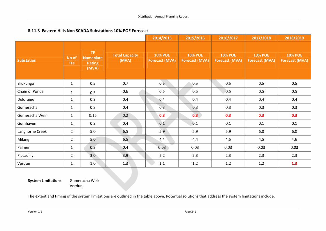
Distribution Annual Planning Report
Version 1.1 Page 241
8.11.3 Eastern Hills Non SCADA Substations 10% POE Forecast
2014/2015 2015/2016 2016/2017 2017/2018 2018/2019
Substation No of
TFs
TF Nameplate
Rating (MVA)
Total Capacity (MVA)
10% POE Forecast (MVA)
10% POE Forecast (MVA)
10% POE Forecast (MVA)
10% POE Forecast (MVA)
10% POE Forecast (MVA)
Brukunga 1 0.5 0.7 0.5 0.5 0.5 0.5 0.5
Chain of Ponds 1 0.5 0.6 0.5 0.5 0.5 0.5 0.5
Deloraine 1 0.3 0.4 0.4 0.4 0.4 0.4 0.4
Gumeracha 1 0.3 0.4 0.3 0.3 0.3 0.3 0.3
Gumeracha Weir 1 0.15 0.2 0.3 0.3 0.3 0.3 0.3
Gumhaven 1 0.3 0.4 0.1 0.1 0.1 0.1 0.1
Langhorne Creek 2 5.0 6.5 5.9 5.9 5.9 6.0 6.0
Milang 2 5.0 6.5 4.4 4.4 4.5 4.5 4.6
Palmer 1 0.3 0.4 0.03 0.03 0.03 0.03 0.03
Piccadilly 2 3.0 3.9 2.2 2.3 2.3 2.3 2.3
Verdun 1 1.0 1.3 1.1 1.2 1.2 1.2 1.3
System Limitations: Gumeracha Weir Verdun The extent and timing of the system limitations are outlined in the table above. Potential solutions that address the system limitations include:

Distribution Annual Planning Report
Version 1.1 Page 242
Upgrade the substation by increasing the capacity; or
Power factor correction to reduce the load at the substation.
The load reduction required to defer the system limitation is the difference between the Forecast and the Total Capacity.
RIT-D’s are not expected to be required for these system limitations.

Distribution Annual Planning Report
Version 1.1 Page 243
8.11.4 Eastern Hills Non SCADA Substations 50% POE Forecast
2014/2015 2015/2016 2016/2017 2017/2018 2018/2019
Substation No of
TFs
TF Nameplate
Rating (MVA)
N-1 Emerg. Cyclic Rating (MVA)
50% POE
F’cast (MVA)
T’fer Cap
(MVA)
50% POE
F’cast (MVA)
T’fer Cap
(MVA)
50% POE
F’cast (MVA)
T’fer Cap
(MVA)
50% POE
F’cast (MVA)
T’fer Cap
(MVA)
50% POE
F’cast (MVA)
T’fer Cap
(MVA)
Langhorne Creek 2 5.0 3.8 5.3* 1.1 5.3* 1.1 5.4* 1.1 5.4* 1.1 5.4* 1.1
Milang 2 5.0 3.8 3.9 1.6 4.0 1.6 4.0 1.6 4.1 1.6 4.1 1.5
*Within planning criteria risk margin System Limitations: Nil

Distribution Annual Planning Report
Version 1.1 Page 244
8.11.5 Eastern Hills 66kV Sub-transmission
Line Name - From
To Total
Capacity^ (MVA)
Forecast 2014/2015
MVA
Forecast 2015/2016
MVA
Forecast 2016/2017
MVA
Forecast 2017/2018
MVA
Forecast 2018/2019
MVA
66KV LINES ON EASTERN HILLS
MOUNT BARKER MT BARKER STH 137.0 51.7 52.1 52.5 52.9 53.4
MOUNT BARKER BALHANNAH 55.4 43.5 44.3 45.1 45.9 46.7
BALHANNAH URAIDLA 40.2 20.9 20.8 20.7 20.6 20.5
URAIDLA MAGILL 40.2 0.0 0.0 0.0 0.0 0.0
MOUNT BARKER HAHNDORF 55.4 4.8 4.7 4.7 4.6 4.6
MT BARKER STH MEADOWS 55.4 6.0 6.2 6.3 6.5 6.7
MT BARKER STH STRATH EAST TEE 34.8 29.3 29.5 29.7 30.0 30.2
STRATH EAST TEE STRATHALBYN 34.8 19.8 19.9 20.0 20.1 20.2
STRATHALBYN BELVIDERE 13.0 10.3 10.3 10.4 10.5 10.6
BELVIDERE MILANG 10.3 4.4 4.4 4.5 4.5 4.6
BELVIDERE LANGHORNE CREEK
13.0 5.9 5.9 5.9 6.0 6.0
^ The published rating is based on a thermal limit or a limit required to maintain adequate clearances and does not take into account voltage limitations on the network which may further reduce the published rating. System Limitations: Nil

Distribution Annual Planning Report
Version 1.1 Page 245
8.11.6 Eastern Hills 33kV Sub-Transmission Lines
Line Name - From
To Total
Capacity^ (MVA)
Forecast 2014/2015
MVA
Forecast 2015/2016
MVA
Forecast 2016/2017
MVA
Forecast 2017/2018
MVA
Forecast 2018/2019
MVA
33kV lines ex Balhannah/Uraidla
Balhannah Woodside 20.1 8.8 8.8 8.8 8.8 8.8
Balhannah Verdun Tee 21.4 3.9 4.0 4.1 4.1 4.2
Balhannah Nairne 13.0 8.2 8.3 8.4 8.5 8.5
Uraidla Piccadilly 20 19.0 19.2 19.4 19.7 19.9
Piccadilly Stirling East 20 16.7 16.9 17.1 17.3 17.5
Verdun Tee Aldgate 20 0.3 0.3 0.3 0.3 0.3
Stirling East Aldgate 20 7.2 7.3 7.4 7.4 7.5
Verdun Tee Mylor 3.4 2.5 2.6 2.6 2.6 2.7
33kV Lines ex Angas Creek
Angas Creek Angas Ck Tee 20.3 13.1 13.0 13.0 12.9 12.9
Angas Ck Tee Lobethal 20.1 6.9 6.8 6.7 6.6 6.5
Lobethal Tee Woodside 7 0.0 0.0 0.0 0.0 0.0
Angas Ck Tee Gumeracha 7 6.2 6.2 6.3 6.3 6.4
Gumeracha Houghton 6 3.9 4.0 4.0 4.1 4.2
Gumeracha Kersbrook 15 2.3 2.2 2.2 2.1 2.1
Kersbrook A4892 6 1.4 1.3 1.3 1.3 1.3
Angas Creek Birdwood Tee 14.5 7.1 7.1 7.0 6.9 6.9
Birdwood Tee Forreston 4.2 1.3 1.3 1.3 1.3 1.3
Forreston LSDF4565 4.2 0.2 0.2 0.2 0.2 0.2
Birdwood Tee Birdwood 4.2 4.9 4.9 4.8 4.7 4.7
Birdwood Mt Pleasant Tee 4.2 2.5 2.6 2.6 2.6 2.7
Mt Pleasant Tee Mt Pleasant 10.7 1.7 1.7 1.6 1.6 1.6
Mt Pleasant Tee Tungkillo 4.2 0.2 0.2 0.2 0.2 0.2
^ The published rating is based on a thermal limit or a limit required to maintain adequate clearances and does not take into account voltage limitations on the network which may further reduce the published rating. System Limitations: Birdwood Tee-Birdwood 33kV line The extent and timing of the system limitations are outlined in the table above. Potential solutions that address the system limitations include:
Upgrade the line by increasing conductor clearances; or
Power factor correction to reduce the load on the line.
The load reduction required to defer the system limitation is the difference between the Forecast and the Total Capacity.
RIT-D’s are not expected to be required for these system limitations.

Distribution Annual Planning Report
Version 1.1 Page 246
8.12 Mid North and Yorke Peninsula Regional Development Plan
The Mid North and Yorke Peninsula The SA Power Networks’ Mid North and Yorke Peninsula region includes the region from Clare extending north to Wilmington, south to Mallala and the Yorke Peninsula. There are several main connection systems in the Mid North and Yorke Peninsula, being Dalrymple, Ardrossan West, Clare North, Hummocks, Kadina East, Brinkworth, Waterloo and Templers. A map of this region can be found at the end of this section. SA Power Networks’ Distribution Network Electricity is supplied to the various towns and localities throughout the Mid North and Yorke Peninsula via Zone Substations. These Zone Substations are operated at 33,000 Volts stepped down to 11,000 or 7,600 Volts.
Customers are supplied from SA Power Networks distribution system via 7.6kV, 11kV and 19kV primary distribution feeders, which emanate from the Zone Substations. These feeders are extended and upgraded as required to meet customer demand and customer connection requests. Large customer projects may require a distribution substation upgrade as well as feeder modifications, therefore SA Power Networks should be notified as early as possible during the planning stages of a project so that customer connection requirements can be met. There are no system limitations forecast for the primary distribution feeders under normal conditions in the Mid North and Yorke Peninsula Region in the next two years.
8.12.1 Mid North and Yorke Peninsula SCADA Substations
Source Connection Point Associated SCADA Substations
Ardrossan West Ardrossan
Maitland
Minlaton
Port Vincent
Brinkworth Brinkworth Town
Clare North Burra Clare
Dalrymple Edithburgh
Stansbury
Port Giles
Warooka
Yorketown
Hummocks Balaklava
Kadina East Moonta Wallaroo
Templers Freeling North
Gawler Belt
Hamley Bridge
Kapunda
Sandy Creek
Waterloo Riverton Waterloo Town

HUMMOCKS
MALLALA
BALAKLAVA
PASKEVILLE
NINNES
COLLINSFIELD
BLYTH
HAMLEY BRIDGE
GAWLER BELT
WASLEYS
TEMPLERS
RIVERTON
FREELINGFREELING NORTH
KAPUNDA
MARRABEL EUDUNDA
AUBURN
CLARE
WATERLOO
CLARE NORTH
BRINKWORTH TOWN
BRINKWORTH
SPALDING
WATERLOO TOWN
ROBERTSTOWN 33/11kV
BURRA
MID NORTHLegend
275kV Transmission Line132kV Transmission Line66kV Sub Transmission Line33kV Sub Transmission LineSubstation
UPPER NORTH
BAROSSA 0 5 10 15 20 25 30
Kilometres
YORKEPENINSULA
System Limitation.

WAROOKA
MOONTA
WALLAROO
YORKETOWN
DALRYMPLE
MINLATON
EDITHBURGH
PORT GILES
KLEINS POINT
STANSBURY
PORT VINCENT
MAITLAND
KADINA
ARDROSSAN WEST
ARDROSSAN
KADINA EAST
HUMMOCKS
PASKEVILLE
NINNES
MARION BAY
MIDNORTH
0 5 10 15 20 25
Kilometres
YORKE PENINSULALegend
275kV Transmission Line132kV Transmission Line66kV Sub Transmission Line33kV Sub Transmission LineSubstation
System Limitation.

Distribution Annual Planning Report
Version 1.1 Page 249
Substation: Ardrossan West 132/33kV
Region: Mid North & Yorke Peninsula
(ETC) Transmission Category: 2
Number of Transformers: 2
Total Nameplate Rating (MVA): 50 MVA
Actuals
Year 2009/2010 2010/2011 2011/2012 2012/2013 2013/2014
Sum
mer
MW 14.1 12.6 11.8 11.6 11.9
MVAr 6.0 4.3 3.4 3.4 3.1
MVA 15.3 13.3 12.3 12.1 12.3
PF 0.92 0.92 0.96 0.96 0.97
Year 2009 2010 2011 2012 2013
Win
ter MW 9.4 10.5 9.8 9.2 8.8
MVAr 1.6 2.0 1.4 0.8 0.2
MVA 9.5 10.7 9.9 9.2 8.8
PF 0.99 0.98 0.99 1.00 1.00
Forecast
Sum
mer
10% POE Forecast 2014/2015 2015/2016 2016/2017 2017/2018 2018/2019
MW 12.0 12.1 10.0 10.2 10.3
MVAr 3.3 3.4 2.8 2.8 2.9
MVA 12.4 12.5 10.4 10.6 10.7
PF 0.96 0.96 0.96 0.96 0.96
Firm Delivery Capacity (MVA) 32.5 32.5 32.5 32.5 32.5
System Limitation (Y/N) N N N N N
Hrs per annum > 95% of Peak Load (hrs) 2
Year Former Step Change (MVA) Year Future Step Change (10% POE MVA)
2016/17 -3.0MVA to Dalrymple

Distribution Annual Planning Report
Version 1.1 Page 250
Substation: Brinkworth 132/33kV
Region: Mid North & Yorke Peninsula
(ETC) Transmission Category: 4
Number of Transformers: 2
Total Nameplate Rating (MVA): 20 MVA
Actuals
Year 2009/2010 2010/2011 2011/2012 2012/2013 2013/2014
Sum
mer
MW 4.8 5.2 4.2 4.7 4.7
MVAr 1.0 0.6 0.1 0.2 0.1
MVA 4.9 5.2 4.2 4.7 4.7
PF 0.98 0.98 1.00 1.00 1.00
Year 2009 2010 2011 2012 2013
Win
ter MW 3.6 4.0 3.7 4.0 4.1
MVAr 0.3 0.0 0.5 0.9 0.8
MVA 3.6 4.0 3.8 4.1 4.1
PF 1.00 1.00 0.99 0.98 0.98
Forecast
Sum
mer
10% POE Forecast 2014/2015 2015/2016 2016/2017 2017/2018 2018/2019
MW 4.6 4.6 4.5 4.5 4.4
MVAr 0.1 0.1 0.1 0.1 0.1
MVA 4.6 4.6 4.5 4.5 4.4
PF 1.00 1.00 1.00 1.00 1.00
Firm Delivery Capacity (MVA) 13.7 13.7 13.7 13.7 13.7
System Limitation (Y/N) N N N N N
Hrs per annum > 95% of Peak Load (hrs) 3
Year Former Step Change (MVA) Year Future Step Change (10% POE MVA)
2009/10 +0.3MVA from Hummocks

Distribution Annual Planning Report
Version 1.1 Page 251
Substation: Clare North 132/33kV
Region: Mid North & Yorke Peninsula
(ETC) Transmission Category: 4
Number of Transformers: 2
Total Nameplate Rating (MVA): 80 MVA
Actuals
Year 2009/2010 2010/2011 2011/2012 2012/2013 2013/2014
Sum
mer
MW N/A 9.7 10.6 12.4 12.4
MVAr N/A 4.3 4.1 4.2 4.4
MVA N/A 10.6 11.4 13.0 13.1
PF N/A 0.92 0.93 0.95 0.94
Year 2009 2010 2011 2012 2013
Win
ter MW N/A 6.9 10.0 10.0 10.4
MVAr N/A 0.9 1.9 1.1 3.9
MVA N/A 6.9 10.2 10.1 11.1
PF N/A 0.99 0.98 0.99 0.94
Forecast
Sum
mer
10% POE Forecast 2014/2015 2015/2016 2016/2017 2017/2018 2018/2019
MW 12.7 12.6 12.6 12.6 12.6
MVAr 4.5 4.5 4.5 4.5 4.5
MVA 13.5 13.4 13.4 13.4 13.3
PF 0.94 0.94 0.94 0.94 0.94
Firm Delivery Capacity (MVA) 40.0 40.0 40.0 40.0 40.0
System Limitation (Y/N) N N N N N
Hrs per annum > 95% of Peak Load (hrs) 8
Year Former Step Change (MVA) Year Future Step Change (10% POE MVA)
2010/11 +13.4MVA from Waterloo

Distribution Annual Planning Report
Version 1.1 Page 252
Substation: Dalrymple 132/33kV
Region: Mid North & Yorke Peninsula
(ETC) Transmission Category: 1, 2 in 2016
Number of Transformers: 1
Total Nameplate Rating (MVA): 25 MVA
Actuals
Year 2009/2010 2010/2011 2011/2012 2012/2013 2013/2014
Sum
mer
MW 9.7 8.6 8.5 8.0 7.9
MVAr 3.7 3.0 2.8 1.7 1.4
MVA 10.4 9.1 9.0 8.1 8.0
PF 0.93 0.94 0.95 0.98 0.98
Year 2009 2010 2011 2012 2013
Win
ter MW 6.6 5.9 6.6 8.6 6.5
MVAr 0.5 0.5 1.4 0.9 1.3
MVA 6.6 5.9 6.8 8.7 6.6
PF 1.00 1.00 0.98 0.99 0.98
Forecast
Sum
mer
10% POE Forecast 2014/2015 2015/2016 2016/2017 2017/2018 2018/2019
MW 7.9 7.9 10.0 9.9 9.9
MVAr 1.9 1.9 2.4 2.4 2.4
MVA 8.1 8.1 10.3 10.2 10.2
PF 0.97 0.97 0.97 0.97 0.97
Firm Delivery Capacity (MVA) 0 0 0 0 0
System Limitation (Y/N) Y* Y* Y* Y* Y*
Hrs per annum > 95% of Peak Load (hrs) 2
Year Former Step Change (MVA) Year Future Step Change (10% POE MVA)
2016/17 +3.0MVA from Ardrossan West
* N-1 capacity not required by ETC until 2016

Distribution Annual Planning Report
Version 1.1 Page 253
Dalrymple 132/33kV Connection Point
System Limitation
Dalrymple 132/33kV Connection Point presently has one 25MVA 132/33kV transformer supplied by a single 132kV transmission line from Hummocks via Ardrossan West and is located approximately 5km south west of the township of Stansbury.
Version 2 of the ETC has changed the security standard for Dalrymple to Category 2 (requires N-1 Capacity) from 2016. As a consequence this connection Point Substation will not comply with the ETC from 2016 and is therefore planned to be upgraded by ElectraNet.
The Transmission Company (Electranet) are managing the RIT-T process for this Transmission Connection Point, refer to http://www.electranet.com.au/assets/RIT-T/Dalrymple-Substation-Upgrade/11826-DalrympleSubstationUpgrade-PSCR-Apr2013.pdf

Distribution Annual Planning Report
Version 1.1 Page 254
Substation: Hummocks 132/33kV
Region: Mid North & Yorke Peninsula
(ETC) Transmission Category: 4
Number of Transformers: 2
Total Nameplate Rating (MVA): 50 MVA
Actuals
Year 2009/2010 2010/2011 2011/2012 2012/2013 2013/2014
Sum
mer
MW 13.9 14.7 12.7 12.6 13.1
MVAr 5.5 6.4 6.0 5.5 5.4
MVA 14.9 16.1 14.0 13.8 14.2
PF 0.93 0.93 0.90 0.92 0.93
Year 2009 2010 2011 2012 2013
Win
ter MW 10.9 11.0 11.3 12.2 10.5
MVAr 2.9 2.8 3.2 3.4 2.8
MVA 11.2 11.3 11.8 12.6 10.9
PF 0.97 0.97 0.96 0.96 0.97
Forecast
Sum
mer
10% POE Forecast 2014/2015 2015/2016 2016/2017 2017/2018 2018/2019
MW 13.3 13.1 13.0 12.9 12.8
MVAr 5.8 5.7 5.7 5.6 5.6
MVA 14.5 14.3 14.2 14.0 13.9
PF 0.92 0.92 0.92 0.92 0.92
Firm Delivery Capacity (MVA) 25 25 25 25 25
System Limitation (Y/N) N N N N N
Hrs per annum > 95% of Peak Load (hrs) 7
Year Former Step Change (MVA) Year Future Step Change (10% POE MVA)
2009/10 -0.3MVA to Brinkworth

Distribution Annual Planning Report
Version 1.1 Page 255
Substation: Kadina East 132/33kV
Region: Mid North & Yorke Peninsula
(ETC) Transmission Category: 2
Number of Transformers: 2
Total Nameplate Rating (MVA): 120 MVA
Actuals
Year 2009/2010 2010/2011 2011/2012 2012/2013 2013/2014
Sum
mer
MW 26.2 25.1 24.8 24.8 24.8
MVAr 9.5 7.9 8.6 8.3 7.6
MVA 27.9 26.3 26.3 26.1 26.0
PF 0.94 0.95 0.94 0.95 0.96
Year 2009 2010 2011 2012 2013
Win
ter MW 16.2 18.1 17.9 19.8 18.4
MVAr 2.8 2.2 4.1 2.5 0.7
MVA 16.5 18.2 18.3 20.0 18.4
PF 0.99 0.99 0.97 0.99 1.00
Forecast
Sum
mer
10% POE Forecast 2014/2015 2015/2016 2016/2017 2017/2018 2018/2019
MW 24.8 25.0 25.1 25.3 25.5
MVAr 8.2 8.2 8.3 8.3 8.4
MVA 26.1 26.3 26.5 26.7 26.9
PF 0.95 0.95 0.95 0.95 0.95
Firm Delivery Capacity (MVA) 60.0 60.0 60.0 60.0 60.0
System Limitation (Y/N) N N N N N
Hrs per annum > 95% of Peak Load (hrs) 3
Year Former Step Change (MVA) Year Future Step Change (10% POE MVA)

Distribution Annual Planning Report
Version 1.1 Page 256
Substation: Templers 132/33kV
Region: Mid North & Yorke Peninsula
(ETC) Transmission Category: 4
Number of Transformers: 2
Total Nameplate Rating (MVA): 120 MVA
Actuals
Year 2009/2010 2010/2011 2011/2012 2012/2013 2013/2014
Sum
mer
MW 32.1 31.0 25.9 29.3 30.2
MVAr 14.1 12.5 9.5 11.1 10.5
MVA 35.1 33.4 27.6 31.3 32.0
PF 0.92 0.93 0.94 0.94 0.95
Year 2009 2010 2011 2012 2013
Win
ter MW 23.3 22.9 22.6 22.4 24.2
MVAr 6.9 6.3 5.7 5.2 5.0
MVA 24.3 23.8 23.3 23.0 24.7
PF 0.96 0.96 0.97 0.97 0.98
Forecast
Sum
mer
10% POE Forecast 2014/2015 2015/2016 2016/2017 2017/2018 2018/2019
MW 29.3 29.2 29.1 29.0 28.8
MVAr 10.7 10.6 10.6 10.5 10.5
MVA 31.2 31.1 30.9 30.8 30.7
PF 0.94 0.94 0.94 0.94 0.94
Firm Delivery Capacity (MVA) 79.8 79.8 79.8 79.8 79.8
System Limitation (Y/N) N N N N N
Hrs per annum > 95% of Peak Load (hrs) 12
Year Former Step Change (MVA) Year Future Step Change (10% POE MVA)

Distribution Annual Planning Report
Version 1.1 Page 257
Substation: Waterloo 132/33kV
Region: Mid North & Yorke Peninsula
(ETC) Transmission Category: 4
Number of Transformers: 2
Total Nameplate Rating (MVA): 50 MVA
Actuals
Year 2009/2010 2010/2011 2011/2012 2012/2013 2013/2014
Sum
mer
MW 26.6 13.2 8.1 7.7 8.2
MVAr 10.5 3.6 3.2 2.3 2.4
MVA 28.6 13.7 8.7 8.0 8.5
PF 0.93 0.96 0.93 0.96 0.96
Year 2009 2010 2011 2012 2013
Win
ter MW 16.5 18.4 7.1 6.9 4.3
MVAr 5.8 4.1 1.8 1.1 0.4
MVA 17.5 18.8 7.3 7.0 4.3
PF 0.94 0.98 0.97 0.99 1.00
Forecast
Sum
mer
10% POE Forecast 2014/2015 2015/2016 2016/2017 2017/2018 2018/2019
MW 8.6 8.5 8.4 8.2 8.1
MVAr 2.8 2.7 2.7 2.7 2.6
MVA 9.0 8.9 8.8 8.7 8.6
PF 0.95 0.95 0.95 0.95 0.95
Total Capacity (MVA) 50 50 50 50 50
System Limitation (Y/N) N N N N N
Hrs per annum > 95% of Peak Load (hrs) 3
Year Former Step Change (MVA) Year Future Step Change (10% POE MVA)
2010/11 -13.4MVA to Clare North

Distribution Annual Planning Report
Version 1.1 Page 258
Substation: Ardrossan 33/11kV
Region: Mid North & Yorke Peninsula
Number of Feeders: 1
Number of Transformers: 3
Total Nameplate Rating (MVA): 3 MVA
Actuals
Year 2009/2010 2010/2011 2011/2012 2012/2013 2013/2014
Sum
mer
MW 2.7 2.5 2.1 2.2 2.3
MVAr 1.1 1.0 0.8 0.9 0.9
MVA 2.9 2.7 2.3 2.4 2.5
PF 0.93 0.93 0.93 0.93 0.93
Year 2009 2010 2011 2012 2013
Win
ter MW 1.7 1.8 1.6 1.8 1.7
MVAr 0.7 0.7 0.6 0.7 0.7
MVA 1.8 2.0 1.7 1.9 1.9
PF 0.93 0.93 0.93 0.93 0.93
Forecast
Sum
mer
10% POE Forecast 2014/2015 2015/2016 2016/2017 2017/2018 2018/2019
MW 2.0 2.0 2.0 2.0 2.0
MVAr 0.8 0.8 0.8 0.8 0.8
MVA 2.2 2.2 2.1 2.2 2.2
PF 0.92 0.92 0.92 0.92 0.92
Total Capacity (MVA) 3.9 3.9 3.9 3.9 3.9
50% POE Forecast
MW 1.7 1.8 1.7 1.7 1.7
MVAr 0.7 0.7 0.7 0.7 0.7
MVA 1.9
1.9
1.8
1.8
1.9 PF 0.92 0.92 0.92 0.92 0.92
Firm Delivery Capacity (MVA) 3.0 3.0 3.0 3.0 3.0
Transfer Capacity (MVA) 0.0
0.0
0.0
0.0
0.0 System Limitation (Y/N) N N N N N
Hrs per annum > 95% of Peak Load (hrs) 3
Year Former Step Change (MVA) Year Future Step Change (10% POE MVA)

Distribution Annual Planning Report
Version 1.1 Page 259
Substation: Balaklava 33/7.6kV
Region: Mid North & Yorke Peninsula
Number of Feeders: 2
Number of Transformers: 2
Total Nameplate Rating (MVA): 5 MVA
Actuals
Year 2009/2010 2010/2011 2011/2012 2012/2013 2013/2014
Sum
mer
MW N/A N/A N/A 2.6 2.9
MVAr N/A N/A N/A 1.2 1.0
MVA N/A N/A N/A 2.9 3.1
PF N/A N/A N/A 0.90 0.94
Year 2009 2010 2011 2012 2013
Win
ter MW N/A N/A N/A 2.2 2.4
MVAr N/A N/A N/A 0.4 0.4
MVA N/A N/A N/A 2.3 2.4
PF N/A N/A N/A 0.99 0.99
Forecast
Sum
mer
10% POE Forecast 2014/2015 2015/2016 2016/2017 2017/2018 2018/2019
MW 2.8 2.7 2.6 2.5 2.4
MVAr 1.2 1.1 1.1 1.0 1.0
MVA 3.0 2.9 2.8 2.7 2.6
PF 0.92 0.92 0.92 0.92 0.92
Total Capacity (MVA) 5.0 5.0 5.0 5.0 5.0
50% POE Forecast
MW 2.6 2.5 2.3 2.3 2.2
MVAr 1.1 1.0 1.0 1.0 0.9
MVA 2.8
2.7
2.6
2.5
2.4 PF 0.92 0.92 0.92 0.92 0.92
Firm Delivery Capacity (MVA) 2.8 2.8 2.8 2.8 2.8
Transfer Capacity (MVA) 0.0
0.0
0.0
0.0
0.0 System Limitation (Y/N) N N N N N
Hrs per annum > 95% of Peak Load (hrs) 3
Year Former Step Change (MVA) Year Future Step Change (10% POE MVA)
2011/12 +0.1MVA customer load increase

Distribution Annual Planning Report
Version 1.1 Page 260
Substation: Brinkworth Town 33/11kV
Region: Mid North & Yorke Peninsula
Number of Feeders: 2
Number of Transformers: 1
Total Nameplate Rating (MVA): 3 MVA
Actuals
Year 2009/2010 2010/2011 2011/2012 2012/2013 2013/2014
Sum
mer
MW N/A N/A 0.8 0.9 0.9
MVAr N/A N/A 0.2 0.2 0.2
MVA N/A N/A 0.8 0.9 0.9
PF N/A N/A 0.98 0.98 0.98
Year 2009 2010 2011 2012 2013
Win
ter MW N/A N/A 0.7 0.7 0.7
MVAr N/A N/A 0.1 0.2 0.2
MVA N/A N/A 0.7 0.8 0.8
PF N/A N/A 0.98 0.98 0.98
Forecast
Sum
mer
10% POE Forecast 2014/2015 2015/2016 2016/2017 2017/2018 2018/2019
MW 0.9 0.8 0.8 0.8 0.8
MVAr 0.2 0.2 0.2 0.2 0.2
MVA 0.9 0.9 0.8 0.8 0.8
PF 0.98 0.98 0.98 0.98 0.98
Total Capacity (MVA) 3.9 3.9 3.9 3.9 3.9
50% POE Forecast
MW 0.8 0.8 0.8 0.8 0.8
MVAr 0.2 0.2 0.2 0.2 0.2
MVA 0.8
0.8
0.8
0.8
0.8 PF 0.98 0.98 0.98 0.98 0.98
Firm Delivery Capacity (MVA) 0.0 0.0 0.0 0.0 0.0
Transfer Capacity (MVA) 0.0
0.0
0.0
0.0
0.0 System Limitation (Y/N) Y* Y* Y* Y* Y*
Hrs per annum > 95% of Peak Load (hrs) 6
Year Former Step Change (MVA) Year Future Step Change (10% POE MVA)
*Within planning criteria risk

Distribution Annual Planning Report
Version 1.1 Page 261
Substation: Burra TF2 33/11kV
Region: Mid North & Yorke Peninsula
Number of Feeders: 2
Number of Transformers: 1
Total Nameplate Rating (MVA): 5 MVA
Actuals
Year 2009/2010 2010/2011 2011/2012 2012/2013 2013/2014
Sum
mer
MW N/A N/A N/A N/A N/A
MVAr N/A N/A N/A N/A N/A
MVA N/A N/A N/A N/A N/A
PF N/A N/A N/A N/A N/A
Year 2009 2010 2011 2012 2013
Win
ter MW N/A N/A N/A 2.1 N/A
MVAr N/A N/A N/A 0.9 N/A
MVA N/A N/A N/A 2.3 N/A
PF N/A N/A N/A 0.92 N/A
Forecast
Sum
mer
10% POE Forecast 2014/2015 2015/2016 2016/2017 2017/2018 2018/2019
MW 2.4 2.4 2.5 2.5 2.6
MVAr 1.0 1.0 1.1 1.1 1.1
MVA 2.6 2.7 2.7 2.7 2.8
PF 0.92 0.92 0.92 0.92 0.92
Total Capacity (MVA) 5.7 5.7 5.7 5.7 5.7
50% POE Forecast
MW 2.3
2.3
2.3
2.3
2.3 MVAr 1.0
1.0
1.0
1.0
1.0
MVA 2.5
2.5
2.5
2.5
2.5 PF 0.92
0.92
0.92
0.92
0.92
Firm Delivery Capacity (MVA) 0.0 0.0 0.0 0.0 0.0
Transfer Capacity (MVA) 4.9
4.9
4.9
4.9
4.9 System Limitation (Y/N) N N N N N
Hrs per annum > 95% of Peak Load (hrs) 6
Year Former Step Change (MVA) Year Future Step Change (10% POE MVA)

Distribution Annual Planning Report
Version 1.1 Page 262
Substation: Clare 33/11kV
Region: Mid North & Yorke Peninsula
Number of Feeders: 4
Number of Transformers: 2
Total Nameplate Rating (MVA): 10 MVA
Actuals
Year 2009/2010 2010/2011 2011/2012 2012/2013 2013/2014
Sum
mer
MW 9.4 9.6 8.0 8.6 9.6
MVAr 2.4 4.5 3.8 3.7 4.0
MVA 9.7 10.6 8.8 9.4 10.4
PF 0.97 0.91 0.91 0.92 0.93
Year 2009 2010 2011 2012 2013
Win
ter MW 6.6 6.9 6.6 6.9 7.5
MVAr 1.0 0.8 2.3 1.2 1.1
MVA 6.6 7.0 7.0 7.0 7.5
PF 0.99 0.99 0.95 0.99 0.99
Forecast
Sum
mer
10% POE Forecast 2014/2015 2015/2016 2016/2017 2017/2018 2018/2019
MW 10.2 10.2 10.2 10.3 10.3
MVAr 4.3 4.3 4.4 4.4 4.4
MVA 11.1 11.1 11.1 11.2 11.2
PF 0.92 0.92 0.92 0.92 0.92
Total Capacity (MVA) 12.6 12.6 12.6 12.6 12.6
50% POE Forecast
MW 9.2 9.2 9.2 9.2 9.3
MVAr 3.9 3.9 3.9 3.9 3.9
MVA 10.0
10.0
10.0
10.0
10.1 PF 0.92 0.92 0.92 0.92 0.92
Firm Delivery Capacity (MVA) 7.1 7.1 7.1 7.1 7.1
Transfer Capacity (MVA) 0.0
0.0
0.0
0.0
0.0 System Limitation (Y/N) Y* Y* Y* Y* Y
Hrs per annum > 95% of Peak Load (hrs) 9
Year Former Step Change (MVA) Year Future Step Change (10% POE MVA)
*Within planning criteria risk

Distribution Annual Planning Report
Version 1.1 Page 263
Clare 33/11kV Zone Substation
System Limitation
Clare 33/11kV Zone Substation has two 5MVA 33/11kV transformers and is located near the township of Clare.
In the summer of 2018/19, up to 3MVA of customer load is forecasted to be unsupplied during a contingent event after all available load transfers have been implemented.
Potential solutions that address the system limitation include:
Upgrade the Clare Substation with two new 12.5MVA 33/11kV transformers (preferred option);
Upgrade adjacent Zone Substation and construct 11kV feeder ties to enable more customer load to be transferred between substations during a contingency.
Due to the extent of the overload during a contingent event, PF correction would not defer this system limitation. A load reduction of at least 3MVA would be required to defer this system limitation for a 12 month period.
A RIT-D is expected to be required for this system limitation with a planned publication date of December 2015.

Distribution Annual Planning Report
Version 1.1 Page 264
Substation: Edithburgh 33/11kV
Region: Mid North & Yorke Peninsula
Number of Feeders: 1
Number of Transformers: 1
Total Nameplate Rating (MVA): 2.5 MVA
Actuals
Year 2009/2010 2010/2011 2011/2012 2012/2013 2013/2014
Sum
mer
MW 1.7 1.4 1.3 1.4 1.3
MVAr 0.7 0.6 0.5 0.5 0.5
MVA 1.8 1.5 1.4 1.4 1.4
PF 0.93 0.93 0.93 0.93 0.94
Year 2009 2010 2011 2012 2013
Win
ter MW 1.4 1.4 1.3 1.3 1.4
MVAr 0.6 0.6 0.5 0.5 0.5
MVA 1.5 1.5 1.4 1.4 1.5
PF 0.93 0.93 0.93 0.93 0.93
Forecast
Sum
mer
10% POE Forecast 2014/2015 2015/2016 2016/2017 2017/2018 2018/2019
MW 1.0 1.0 1.0 1.0 1.0
MVAr 0.4 0.4 0.4 0.4 0.4
MVA 1.1 1.1 1.1 1.1 1.0
PF 0.93 0.93 0.93 0.93 0.93
Total Capacity (MVA) 3.0 3.0 3.0 3.0 3.0
50% POE Forecast
MW 0.9 0.9 0.9 0.9 0.9
MVAr 0.3 0.3 0.3 0.3 0.3
MVA 0.9
0.9
1.0
1.0
0.9 PF 0.93 0.93 0.93 0.93 0.93
Firm Delivery Capacity (MVA) 0.0 0.0 0.0 0.0 0.0
Transfer Capacity (MVA) 1.3
1.3
1.3
1.3
1.3 System Limitation (Y/N) N N N N N
Hrs per annum > 95% of Peak Load (hrs) 2
Year Former Step Change (MVA) Year Future Step Change (10% POE MVA)

Distribution Annual Planning Report
Version 1.1 Page 265
Substation: Freeling North 33/11kV
Region: Mid North & Yorke Peninsula
Number of Feeders: 1
Number of Transformers: 1
Total Nameplate Rating (MVA): 3.8 MVA
Actuals
Year 2009/2010 2010/2011 2011/2012 2012/2013 2013/2014
Sum
mer
MW N/A N/A 1.7 2.2 2.3
MVAr N/A N/A 0.6 0.9 0.9
MVA N/A N/A 1.8 2.4 2.5
PF N/A N/A 0.94 0.93 0.94
Year 2009 2010 2011 2012 2013
Win
ter MW N/A N/A N/A 1.9 1.8
MVAr N/A N/A N/A 0.7 0.7
MVA N/A N/A N/A 2.0 2.0
PF N/A N/A N/A 0.93 0.93
Forecast
Sum
mer
10% POE Forecast 2014/2015 2015/2016 2016/2017 2017/2018 2018/2019
MW 2.2 2.1 2.1 2.0 2.0
MVAr 0.8 0.8 0.8 0.8 0.8
MVA 2.3 2.3 2.2 2.2 2.1
PF 0.93 0.93 0.93 0.93 0.93
Total Capacity (MVA) 4.3 4.3 4.3 4.3 4.3
50% POE Forecast
MW 2.0 1.9 1.9 1.8 1.8
MVAr 0.8 0.7 0.7 0.7 0.7
MVA 2.1
2.1
2.0
2.0
1.9 PF 0.93 0.93 0.93 0.93 0.93
Firm Delivery Capacity (MVA) 0.0 0.0 0.0 0.0 0.0
Transfer Capacity (MVA) 3.7
3.8
3.9
4.1
4.2 System Limitation (Y/N) N N N N N
Hrs per annum > 95% of Peak Load (hrs) 6
Year Former Step Change (MVA) Year Future Step Change (10% POE MVA)
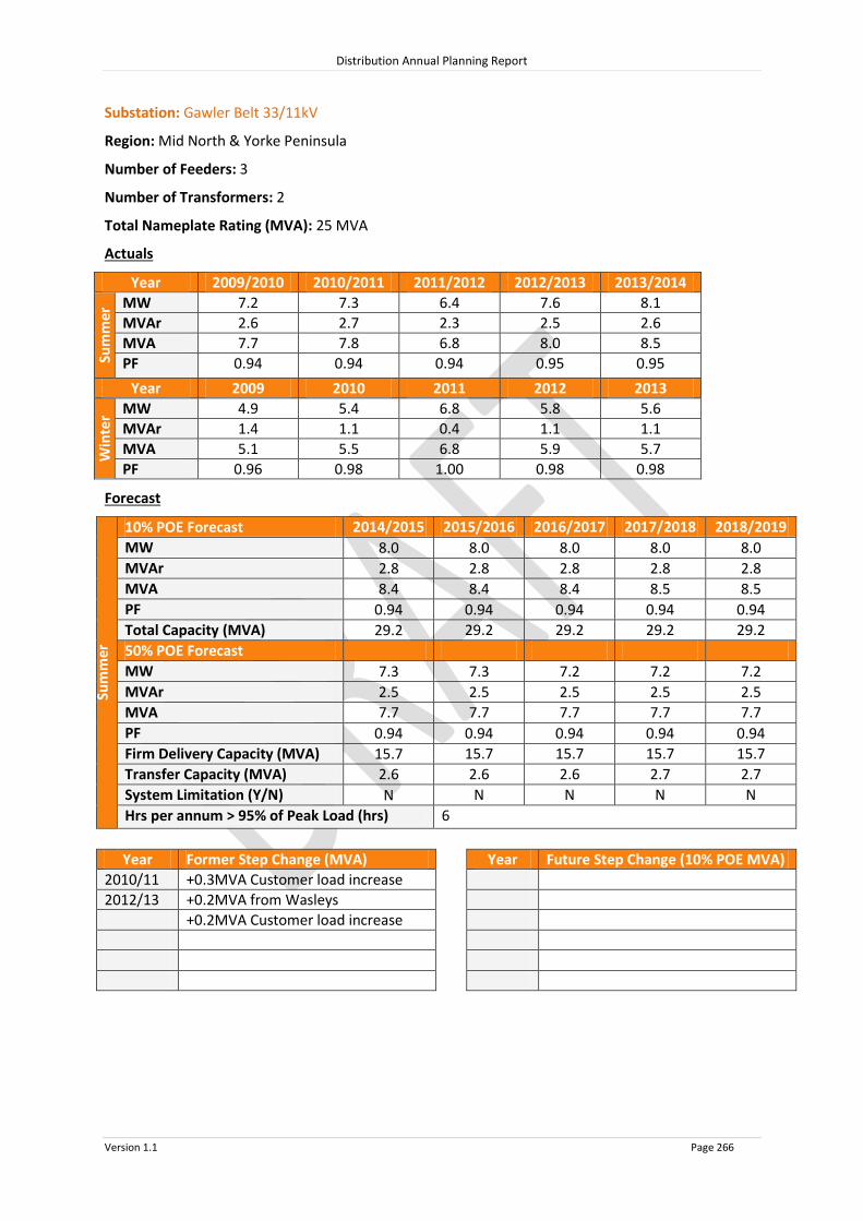
Distribution Annual Planning Report
Version 1.1 Page 266
Substation: Gawler Belt 33/11kV
Region: Mid North & Yorke Peninsula
Number of Feeders: 3
Number of Transformers: 2
Total Nameplate Rating (MVA): 25 MVA
Actuals
Year 2009/2010 2010/2011 2011/2012 2012/2013 2013/2014
Sum
mer
MW 7.2 7.3 6.4 7.6 8.1
MVAr 2.6 2.7 2.3 2.5 2.6
MVA 7.7 7.8 6.8 8.0 8.5
PF 0.94 0.94 0.94 0.95 0.95
Year 2009 2010 2011 2012 2013
Win
ter MW 4.9 5.4 6.8 5.8 5.6
MVAr 1.4 1.1 0.4 1.1 1.1
MVA 5.1 5.5 6.8 5.9 5.7
PF 0.96 0.98 1.00 0.98 0.98
Forecast
Sum
mer
10% POE Forecast 2014/2015 2015/2016 2016/2017 2017/2018 2018/2019
MW 8.0 8.0 8.0 8.0 8.0
MVAr 2.8 2.8 2.8 2.8 2.8
MVA 8.4 8.4 8.4 8.5 8.5
PF 0.94 0.94 0.94 0.94 0.94
Total Capacity (MVA) 29.2 29.2 29.2 29.2 29.2
50% POE Forecast
MW 7.3 7.3 7.2 7.2 7.2
MVAr 2.5 2.5 2.5 2.5 2.5
MVA 7.7
7.7
7.7
7.7
7.7 PF 0.94 0.94 0.94 0.94 0.94
Firm Delivery Capacity (MVA) 15.7 15.7 15.7 15.7 15.7
Transfer Capacity (MVA) 2.6
2.6
2.6
2.7
2.7 System Limitation (Y/N) N N N N N
Hrs per annum > 95% of Peak Load (hrs) 6
Year Former Step Change (MVA) Year Future Step Change (10% POE MVA)
2010/11 +0.3MVA Customer load increase
2012/13 +0.2MVA from Wasleys
+0.2MVA Customer load increase

Distribution Annual Planning Report
Version 1.1 Page 267
Substation: Hamley Bridge 33/11kV
Region: Mid North & Yorke Peninsula
Number of Feeders: 1
Number of Transformers: 1
Total Nameplate Rating (MVA): 2.5 MVA
Actuals
Year 2009/2010 2010/2011 2011/2012 2012/2013 2013/2014
Sum
mer
MW N/A N/A N/A 1.9 2.0
MVAr N/A N/A N/A 0.9 0.9
MVA N/A N/A N/A 2.1 2.2
PF N/A N/A N/A 0.91 0.92
Year 2009 2010 2011 2012 2013
Win
ter MW N/A N/A N/A N/A 1.4
MVAr N/A N/A N/A N/A 0.3
MVA N/A N/A N/A N/A 1.4
PF N/A N/A N/A N/A 0.98
Forecast
Sum
mer
10% POE Forecast 2014/2015 2015/2016 2016/2017 2017/2018 2018/2019
MW 2.5 2.5 2.5 2.5 2.4
MVAr 0.9 0.9 0.9 0.9 0.9
MVA 2.7 2.7 2.6 2.6 2.6
PF 0.94 0.94 0.94 0.94 0.94
Total Capacity (MVA) 3.0 3.0 3.0 3.0 3.0
50% POE Forecast
MW 2.3 2.3 2.2 2.2 2.2
MVAr 0.8 0.8 0.8 0.8 0.8
MVA 2.4
2.4
2.4
2.4
2.3 PF 0.94 0.94 0.94 0.94 0.94
Firm Delivery Capacity (MVA) 0.0 0.0 0.0 0.0 0.0
Transfer Capacity (MVA) 0.0
0.0
0.0
0.0
0.0 System Limitation (Y/N) Y* Y* Y* Y* Y*
Hrs per annum > 95% of Peak Load (hrs) 5
Year Former Step Change (MVA) Year Future Step Change (10% POE MVA)
*Within planning criteria risk margin

Distribution Annual Planning Report
Version 1.1 Page 268
Substation: Kadina 33/11kV
Region: Mid North & Yorke Peninsula
Number of Feeders: 3
Number of Transformers: 2
Total Nameplate Rating (MVA): 12.5 MVA
Actuals
Year 2009/2010 2010/2011 2011/2012 2012/2013 2013/2014
Sum
mer
MW 8.9 9.1 7.9 8.0 9.0
MVAr 2.8 2.7 2.4 2.3 2.6
MVA 9.3 9.5 8.3 8.3 9.4
PF 0.96 0.96 0.96 0.96 0.96
Year 2009 2010 2011 2012 2013
Win
ter MW 5.9 6.3 6.2 6.3 6.4
MVAr 0.3 0.6 0.5 0.0 0.0
MVA 5.9 6.4 6.2 6.3 6.4
PF 1.00 1.00 1.00 1.00 1.00
Forecast
Sum
mer
10% POE Forecast 2014/2015 2015/2016 2016/2017 2017/2018 2018/2019
MW 8.8 8.8 8.8 8.8 8.8
MVAr 2.6 2.6 2.6 2.6 2.6
MVA 9.2 9.2 9.2 9.1 9.1
PF 0.96 0.96 0.96 0.96 0.96
Total Capacity (MVA) 16.0 16.0 16.0 16.0 16.0
50% POE Forecast
MW 7.9 7.9 7.9 7.8 7.8
MVAr 2.3 2.3 2.3 2.3 2.3
MVA 8.3
8.2
8.2
8.2
8.2 PF 0.96 0.96 0.96 0.96 0.96
Firm Delivery Capacity (MVA) 8.8 8.8 8.8 8.8 8.8
Transfer Capacity (MVA) 0.0
0.0
0.0
0.0
0.0 System Limitation (Y/N) N N N N N
Hrs per annum > 95% of Peak Load (hrs) 7
Year Former Step Change (MVA) Year Future Step Change (10% POE MVA)

Distribution Annual Planning Report
Version 1.1 Page 269
Substation: Kapunda 33/11kV
Region: Mid North & Yorke Peninsula
Number of Feeders: 2
Number of Transformers: 2
Total Nameplate Rating (MVA): 25 MVA
Actuals
Year 2009/2010 2010/2011 2011/2012 2012/2013 2013/2014
Sum
mer
MW 5.5 5.8 5.3 5.3 5.7
MVAr 2.3 2.3 2.0 1.9 1.8
MVA 5.9 6.2 5.6 5.6 6.0
PF 0.93 0.94 0.95 0.94 0.95
Year 2009 2010 2011 2012 2013
Win
ter MW 5.1 5.1 5.0 5.2 5.4
MVAr 1.1 1.3 1.0 1.0 1.1
MVA 5.2 5.3 5.1 5.3 5.5
PF 0.98 0.97 0.98 0.98 0.98
Forecast
Sum
mer
10% POE Forecast 2014/2015 2015/2016 2016/2017 2017/2018 2018/2019
MW 5.5 5.5 5.5 5.4 5.4
MVAr 1.8 1.8 1.8 1.8 1.8
MVA 5.8 5.8 5.7 5.7 5.7
PF 0.95 0.95 0.95 0.95 0.95
Total Capacity (MVA) 34.8 34.8 34.8 34.8 34.8
50% POE Forecast
MW 5.1 5.0 5.0 5.0 5.0
MVAr 1.7 1.7 1.6 1.6 1.6
MVA 5.3
5.3
5.3
5.3
5.3 PF 0.95 0.95 0.95 0.95 0.95
Firm Delivery Capacity (MVA) 18.6 18.6 18.6 18.6 18.6
Transfer Capacity (MVA) 0.6
0.6
0.6
0.6
0.6 System Limitation (Y/N) N N N N N
Hrs per annum > 95% of Peak Load (hrs) 7
Year Former Step Change (MVA) Year Future Step Change (10% POE MVA)
2012/13 +0.6MVA Customer load increase

Distribution Annual Planning Report
Version 1.1 Page 270
Substation: Maitland 33/11kV
Region: Mid North & Yorke Peninsula
Number of Feeders: 3
Number of Transformers: 2
Total Nameplate Rating (MVA): 5 MVA
Actuals
Year 2009/2010 2010/2011 2011/2012 2012/2013 2013/2014
Sum
mer
MW 4.1 3.9 3.8 3.5 3.6
MVAr 1.5 1.6 1.5 1.7 1.4
MVA 4.4 4.2 4.1 3.9 3.9
PF 0.94 0.93 0.93 0.90 0.93
Year 2009 2010 2011 2012 2013
Win
ter MW 2.8 3.2 2.9 3.3 2.7
MVAr 1.1 1.3 1.1 1.5 1.3
MVA 3.1 3.4 3.1 3.6 3.0
PF 0.93 0.93 0.93 0.90 0.90
Forecast
Sum
mer
10% POE Forecast 2014/2015 2015/2016 2016/2017 2017/2018 2018/2019
MW 3.3 3.3 3.1 3.1 3.0
MVAr 1.4 1.4 1.3 1.3 1.3
MVA 3.6 3.5 3.4 3.3 3.3
PF 0.92 0.92 0.92 0.92 0.92
Total Capacity (MVA) 7.1 7.1 7.1 7.1 7.1
50% POE Forecast
MW 3.0 2.9 2.7 2.7 2.6
MVAr 1.2 1.2 1.1 1.1 1.1
MVA 3.2
3.1
2.9
2.9
2.8 PF 0.92 0.92 0.92 0.92 0.92
Firm Delivery Capacity (MVA) 3.8 3.8 3.8 3.8 3.8
Transfer Capacity (MVA) 0.0
0.0
0.0
0.0
0.0 System Limitation (Y/N) N N N N N
Hrs per annum > 95% of Peak Load (hrs) 2
Year Former Step Change (MVA) Year Future Step Change (10% POE MVA)

Distribution Annual Planning Report
Version 1.1 Page 271
Substation: Minlaton 33/11kV
Region: Mid North & Yorke Peninsula
Number of Feeders: 2
Number of Transformers: 2
Total Nameplate Rating (MVA): 2 MVA
Actuals
Year 2009/2010 2010/2011 2011/2012 2012/2013 2013/2014
Sum
mer
MW 2.4 1.9 2.1 1.8 2.1
MVAr 0.5 0.4 0.4 0.3 0.5
MVA 2.4 1.9 2.1 1.8 2.1
PF 0.98 0.98 0.98 0.98 0.97
Year 2009 2010 2011 2012 2013
Win
ter MW 1.5 1.7 1.4 1.8 1.7
MVAr 0.3 0.3 0.3 0.3 0.4
MVA 1.5 1.7 1.4 1.8 1.8
PF 0.98 0.99 0.98 0.98 0.97
Forecast
Sum
mer
10% POE Forecast 2014/2015 2015/2016 2016/2017 2017/2018 2018/2019
MW 1.9 1.9 1.8 1.8 1.8
MVAr 0.6 0.6 0.6 0.6 0.6
MVA 2.0 2.0 1.9 1.9 1.9
PF 0.95 0.95 0.95 0.95 0.95
Total Capacity (MVA) 2.6 2.6 2.6 2.6 2.6
50% POE Forecast
MW 1.7 1.7 1.6 1.6 1.6
MVAr 0.6 0.6 0.5 0.6 0.6
MVA 1.8
1.8
1.7
1.7
1.7 PF 0.95 0.95 0.95 0.95 0.95
Firm Delivery Capacity (MVA) 1.5 1.5 1.5 1.5 1.5
Transfer Capacity (MVA) 0.3
0.3
0.3
0.3
0.3 System Limitation (Y/N) N N N N N
Hrs per annum > 95% of Peak Load (hrs) 2
Year Former Step Change (MVA) Year Future Step Change (10% POE MVA)
2011/12 0.5MVAr Capacitor Bank installed

Distribution Annual Planning Report
Version 1.1 Page 272
Substation: Moonta 33/11kV
Region: Mid North & Yorke Peninsula
Number of Feeders: 2
Number of Transformers: 2
Total Nameplate Rating (MVA): 10 MVA
Actuals
Year 2009/2010 2010/2011 2011/2012 2012/2013 2013/2014
Sum
mer
MW 9.0 8.5 9.4 8.5 8.4
MVAr 1.8 1.7 1.9 1.7 1.7
MVA 9.2 8.7 9.6 8.7 8.6
PF 0.98 0.98 0.98 0.98 0.98
Year 2009 2010 2011 2012 2013
Win
ter MW 5.8 5.9 6.6 7.3 6.6
MVAr 0.0 0.0 0.0 1.2 1.6
MVA 5.8 5.9 6.6 7.4 6.8
PF 1.00 1.00 1.00 0.99 0.97
Forecast
Sum
mer
10% POE Forecast 2014/2015 2015/2016 2016/2017 2017/2018 2018/2019
MW 8.1 8.3 8.4 8.6 8.8
MVAr 1.9 1.9 2.0 2.0 2.1
MVA 8.3 8.5 8.7 8.8 9.0
PF 0.97 0.97 0.97 0.97 0.97
Total Capacity (MVA) 12.8 12.8 12.8 12.8 12.8
50% POE Forecast
MW 7.1 7.3 7.4 7.6 7.8
MVAr 1.7 1.7 1.7 1.8 1.8
MVA 7.3
7.5
7.6
7.8
8.0 PF 0.97 0.97 0.97 0.97 0.97
Firm Delivery Capacity (MVA) 7.1 7.1 7.1 7.1 7.1
Transfer Capacity (MVA) 0.0
0.0
0.0
0.0
0.0 System Limitation (Y/N) Y* Y* Y* Y* Y*
Hrs per annum > 95% of Peak Load (hrs) 6
Year Former Step Change (MVA) Year Future Step Change (10% POE MVA)
*Within planning criteria risk margin

Distribution Annual Planning Report
Version 1.1 Page 273
Substation: Port Clinton 33/11kV
Region: Mid North & Yorke Peninsula
Number of Feeders: 1
Number of Transformers: 1
Total Nameplate Rating (MVA): 1 MVA
Actuals
Year 2009/2010 2010/2011 2011/2012 2012/2013 2013/2014
Sum
mer
MW N/A N/A N/A N/A N/A
MVAr N/A N/A N/A N/A N/A
MVA N/A N/A N/A N/A N/A
PF N/A N/A N/A N/A N/A
Year 2009 2010 2011 2012 2013
Win
ter MW N/A N/A N/A N/A N/A
MVAr N/A N/A N/A N/A N/A
MVA N/A N/A N/A N/A N/A
PF N/A N/A N/A N/A N/A
Forecast
Sum
mer
10% POE Forecast 2014/2015 2015/2016 2016/2017 2017/2018 2018/2019
MW 0.6 0.7 0.7 0.7 0.7
MVAr 0.2 0.2 0.2 0.2 0.2
MVA 0.7 0.7 0.7 0.7 0.7
PF 0.97 0.97 0.97 0.97 0.97
Total Capacity (MVA) 1.3 1.3 1.3 1.3 1.3
50% POE Forecast
MW 0.6
0.6
0.6
0.6
0.6 MVAr 0.1
0.2
0.2
0.2
0.2
MVA 0.6
0.6
0.6
0.6
0.6 PF 0.97
0.97
0.97
0.97
0.97
Firm Delivery Capacity (MVA) 0.0 0.0 0.0 0.0 0.0
Transfer Capacity (MVA) 0.0
0.0
0.0
0.0
0.0 System Limitation (Y/N) Y* Y* Y* Y* Y*
Hrs per annum > 95% of Peak Load (hrs) 2
Year Former Step Change (MVA) Year Future Step Change (10% POE MVA)
*Within planning criteria risk margin

Distribution Annual Planning Report
Version 1.1 Page 274
Substation: Port Giles 33/11kV
Region: Mid North & Yorke Peninsula
Number of Feeders: 2
Number of Transformers: 1
Total Nameplate Rating (MVA): 2.5 MVA
Actuals
Year 2009/2010 2010/2011 2011/2012 2012/2013 2013/2014
Sum
mer
MW N/A N/A N/A N/A N/A
MVAr N/A N/A N/A N/A N/A
MVA N/A N/A N/A N/A N/A
PF N/A N/A N/A N/A N/A
Year 2009 2010 2011 2012 2013
Win
ter MW N/A N/A N/A N/A N/A
MVAr N/A N/A N/A N/A N/A
MVA N/A N/A N/A N/A N/A
PF N/A N/A N/A N/A N/A
Forecast
Sum
mer
10% POE Forecast 2014/2015 2015/2016 2016/2017 2017/2018 2018/2019
MW 1.9 1.9 1.9 1.9 1.9
MVAr 0.4 0.4 0.4 0.4 0.4
MVA 1.9 1.9 1.9 1.9 1.9
PF 0.98 0.98 0.98 0.98 0.98
Total Capacity (MVA) 3.3 3.3 3.3 3.3 3.3
50% POE Forecast
MW 1.7 1.7 1.7 1.7 1.7
MVAr 0.3 0.3 0.3 0.3 0.3
MVA 1.7
1.7
1.7
1.7
1.7 PF 0.98 0.98 0.98 0.98 0.98
Firm Delivery Capacity (MVA) 0.0 0.0 0.0 0.0 0.0
Transfer Capacity (MVA) 1.8
1.8
1.8
1.8
1.8 System Limitation (Y/N) N N N N N
Hrs per annum > 95% of Peak Load (hrs) 2
Year Former Step Change (MVA) Year Future Step Change (10% POE MVA)

Distribution Annual Planning Report
Version 1.1 Page 275
Substation: Port Vincent 33/11kV
Region: Mid North & Yorke Peninsula
Number of Feeders: 1
Number of Transformers: 2
Total Nameplate Rating (MVA): 2 MVA
Actuals
Year 2009/2010 2010/2011 2011/2012 2012/2013 2013/2014
Sum
mer
MW N/A 1.6 1.3 1.3 1.2
MVAr N/A 0.6 0.5 0.5 0.3
MVA N/A 1.8 1.4 1.4 1.3
PF N/A 0.93 0.93 0.93 0.97
Year 2009 2010 2011 2012 2013
Win
ter MW 1.1 1.0 1.2 1.1 1.0
MVAr 0.5 0.4 0.5 0.4 0.4
MVA 1.2 1.0 1.3 1.1 1.1
PF 0.93 0.93 0.93 0.93 0.93
Forecast
Sum
mer
10% POE Forecast 2014/2015 2015/2016 2016/2017 2017/2018 2018/2019
MW 1.5 1.5 1.5 1.6 1.6
MVAr 0.4 0.4 0.4 0.4 0.4
MVA 1.5 1.6 1.6 1.6 1.7
PF 0.97 0.97 0.97 0.97 0.97
Total Capacity (MVA) 2.6 2.6 2.6 2.6 2.6
50% POE Forecast
MW 1.3 1.4 1.4 1.4 1.5
MVAr 0.3 0.3 0.3 0.4 0.4
MVA 1.4
1.4
1.4
1.5
1.5 PF 0.97 0.97 0.97 0.97 0.97
Firm Delivery Capacity (MVA) 1.5 1.5 1.5 1.5 1.5
Transfer Capacity (MVA) 0.0
0.0
0.0
0.0
0.0 System Limitation (Y/N) N N N N N
Hrs per annum > 95% of Peak Load (hrs) 2
Year Former Step Change (MVA) Year Future Step Change (10% POE MVA)

Distribution Annual Planning Report
Version 1.1 Page 276
Substation: Riverton 33/11kV
Region: Mid North & Yorke Peninsula
Number of Feeders: 1
Number of Transformers: 1
Total Nameplate Rating (MVA): 3 MVA
Actuals
Year 2009/2010 2010/2011 2011/2012 2012/2013 2013/2014
Sum
mer
MW N/A N/A N/A 1.7 1.8
MVAr N/A N/A N/A 0.7 0.6
MVA N/A N/A N/A 1.8 1.9
PF N/A N/A N/A 0.93 0.94
Year 2009 2010 2011 2012 2013
Win
ter MW N/A N/A N/A N/A 1.5
MVAr N/A N/A N/A N/A 0.3
MVA N/A N/A N/A N/A 1.5
PF N/A N/A N/A N/A 0.99
Forecast
Sum
mer
10% POE Forecast 2014/2015 2015/2016 2016/2017 2017/2018 2018/2019
MW 2.3 2.3 2.2 2.3 2.3
MVAr 0.7 0.7 0.7 0.7 0.7
MVA 2.4 2.4 2.4 2.3 2.3
PF 0.95 0.95 0.95 0.95 0.95
Total Capacity (MVA) 3.9 3.9 3.9 3.9 3.9
50% POE Forecast
MW 2.1
2.0 2.0 2.0 2.0
MVAr 0.7 0.7 0.7 0.7 0.7
MVA 2.2
2.1
2.1 2.1 2.1
PF 0.95 0.95 0.95 0.95 0.95
Firm Delivery Capacity (MVA) 0.0 0.0 0.0 0.0 0.0
Transfer Capacity (MVA) 0.0
0.0
0.0
0.0
0.0 System Limitation (Y/N) Y* Y* Y* Y* Y*
Hrs per annum > 95% of Peak Load (hrs) 2
Year Former Step Change (MVA) Year Future Step Change (10% POE MVA)
*Within planning criteria risk

Distribution Annual Planning Report
Version 1.1 Page 277
Substation: Sandy Creek 33/11kV
Region: Mid North & Yorke Peninsula
Number of Feeders: 2
Number of Transformers: 1
Total Nameplate Rating (MVA): 3 MVA
Actuals
Year 2009/2010 2010/2011 2011/2012 2012/2013 2013/2014
Sum
mer
MW N/A 1.8 1.6 1.8 1.9
MVAr N/A 0.6 0.6 0.7 0.7
MVA N/A 1.9 1.7 1.9 2.1
PF N/A 0.95 0.94 0.93 0.94
Year 2009 2010 2011 2012 2013
Win
ter MW N/A 1.3 1.2 1.3 1.2
MVAr N/A 0.3 0.2 0.5 0.2
MVA N/A 1.3 1.3 1.4 1.2
PF N/A 0.98 0.98 0.93 0.99
Forecast
Sum
mer
10% POE Forecast 2014/2015 2015/2016 2016/2017 2017/2018 2018/2019
MW 1.7 1.7 1.6 1.6 1.5
MVAr 0.6 0.6 0.6 0.6 0.6
MVA 1.8 1.8 1.7 1.7 1.6
PF 0.94 0.94 0.94 0.94 0.94
Total Capacity (MVA) 3.9 3.9 3.9 3.9 3.9
50% POE Forecast
MW 1.6 1.5 1.5 1.4 1.4
MVAr 0.6 0.5 0.5 0.5 0.5
MVA 1.7
1.6
1.6
1.5
1.5 PF 0.94 0.94 0.94 0.94 0.94
Firm Delivery Capacity (MVA) 0.0 0.0 0.0 0.0 0.0
Transfer Capacity (MVA) 0.0
0.0
0.0
0.0
0.0 System Limitation (Y/N) Y* Y* Y* Y* Y*
Hrs per annum > 95% of Peak Load (hrs) 5
Year Former Step Change (MVA) Year Future Step Change (10% POE MVA)
*Within planning criteria risk

Distribution Annual Planning Report
Version 1.1 Page 278
Substation: Stansbury 33/11kV
Region: Mid North & Yorke Peninsula
Number of Feeders: 2
Number of Transformers: 1
Total Nameplate Rating (MVA): 2.5 MVA
Actuals
Year 2009/2010 2010/2011 2011/2012 2012/2013 2013/2014
Sum
mer
MW 1.5 1.1 1.1 1.1 1.1
MVAr 0.6 0.4 0.4 0.4 0.3
MVA 1.6 1.2 1.2 1.2 1.1
PF 0.93 0.93 0.93 0.93 0.96
Year 2009 2010 2011 2012 2013
Win
ter MW 1.0 0.9 1.0 0.9 0.9
MVAr 0.3 0.4 0.4 0.4 0.4
MVA 1.0 1.0 1.1 1.0 1.0
PF 0.94 0.93 0.93 0.93 0.93
Forecast
Sum
mer
10% POE Forecast 2014/2015 2015/2016 2016/2017 2017/2018 2018/2019
MW 0.9 0.8 0.8 0.8 0.8
MVAr 0.3 0.3 0.3 0.3 0.3
MVA 0.9 0.9 0.9 0.9 0.9
PF 0.94 0.94 0.94 0.94 0.94
Total Capacity (MVA) 2.7 2.7 2.7 2.7 2.7
50% POE Forecast
MW 0.8 0.7 0.8 0.7 0.7
MVAr 0.3 0.3 0.3 0.3 0.3
MVA 0.8
0.8
0.8
0.8
0.7 PF 0.94 0.94 0.94 0.94 0.94
Firm Delivery Capacity (MVA) 0.0 0.0 0.0 0.0 0.0
Transfer Capacity (MVA) 0.0
0.0
0.0
0.0
0.0 System Limitation (Y/N) Y* Y* Y* Y* Y*
Hrs per annum > 95% of Peak Load (hrs) 7
Year Former Step Change (MVA) Year Future Step Change (10% POE MVA)
*Within planning criteria risk

Distribution Annual Planning Report
Version 1.1 Page 279
Substation: Wallaroo 33/11kV
Region: Mid North & Yorke Peninsula
Number of Feeders: 2
Number of Transformers: 2
Total Nameplate Rating (MVA): 12.5 MVA
Actuals
Year 2009/2010 2010/2011 2011/2012 2012/2013 2013/2014
Sum
mer
MW 8.1 8.2 7.8 7.8 7.7
MVAr 3.2 3.2 3.1 3.1 2.4
MVA 8.8 8.8 8.4 8.4 8.1
PF 0.93 0.93 0.93 0.93 0.96
Year 2009 2010 2011 2012 2013
Win
ter MW 5.2 4.9 5.4 6.4 5.4
MVAr 2.1 1.9 2.1 2.5 2.3
MVA 5.6 5.3 5.8 6.9 5.8
PF 0.93 0.93 0.93 0.93 0.92
Forecast
Sum
mer
10% POE Forecast 2014/2015 2015/2016 2016/2017 2017/2018 2018/2019
MW 7.5 7.5 7.5 7.6 7.6
MVAr 2.9 2.9 2.9 2.9 2.9
MVA 8.0 8.1 8.1 8.1 8.2
PF 0.93 0.93 0.93 0.93 0.93
Total Capacity (MVA) 16.2 16.2 16.2 16.2 16.2
50% POE Forecast
MW 6.7 6.7 6.7 6.7 6.7
MVAr 2.6 2.6 2.6 2.6 2.6
MVA 7.1
7.2
7.2
7.2
7.2 PF 0.93 0.93 0.93 0.93 0.93
Firm Delivery Capacity (MVA) 9.0 9.0 9.0 9.0 9.0
Transfer Capacity (MVA) 0.0
0.0
0.0
0.0
0.0 System Limitation (Y/N) N N N N N
Hrs per annum > 95% of Peak Load (hrs) 6
Year Former Step Change (MVA) Year Future Step Change (10% POE MVA)
2010/11 +0.4MVA Customer load increase

Distribution Annual Planning Report
Version 1.1 Page 280
Substation: Warooka 33/11kV
Region: Mid North & Yorke Peninsula
Number of Feeders: 2
Number of Transformers: 2
Total Nameplate Rating (MVA): 5 MVA
Actuals
Year 2009/2010 2010/2011 2011/2012 2012/2013 2013/2014
Sum
mer
MW 2.6 2.4 2.5 2.0 1.9
MVAr 1.0 0.9 1.0 0.8 0.6
MVA 2.8 2.5 2.7 2.1 2.0
PF 0.93 0.93 0.93 0.93 0.96
Year 2009 2010 2011 2012 2013
Win
ter MW 1.6 1.7 1.5 1.4 1.4
MVAr 0.6 0.7 0.6 0.6 0.6
MVA 1.7 1.8 1.6 1.5 1.5
PF 0.93 0.93 0.93 0.93 0.93
Forecast
Sum
mer
10% POE Forecast 2014/2015 2015/2016 2016/2017 2017/2018 2018/2019
MW 1.6 1.6 1.7 1.7 1.7
MVAr 0.6 0.6 0.6 0.6 0.6
MVA 1.7 1.7 1.8 1.8 1.8
PF 0.94 0.94 0.94 0.94 0.94
Total Capacity (MVA) 5.4 5.4 5.4 5.4 5.4
50% POE Forecast
MW 1.4 1.4 1.5 1.5 1.5
MVAr 0.5 0.5 0.6 0.6 0.6
MVA 1.5
1.5
1.6
1.6
1.6 PF 0.94 0.94 0.94 0.94 0.94
Firm Delivery Capacity (MVA) 3.0 3.0 3.0 3.0 3.0
Transfer Capacity (MVA) 0.0
0.0
0.0
0.0
0.0 System Limitation (Y/N) N N N N N
Hrs per annum > 95% of Peak Load (hrs) 2
Year Former Step Change (MVA) Year Future Step Change (10% POE MVA)
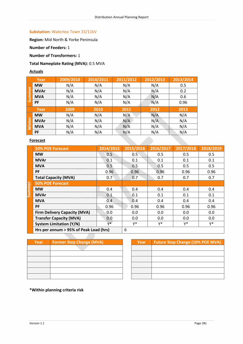
Distribution Annual Planning Report
Version 1.1 Page 281
Substation: Waterloo Town 33/11kV
Region: Mid North & Yorke Peninsula
Number of Feeders: 1
Number of Transformers: 1
Total Nameplate Rating (MVA): 0.5 MVA
Actuals
Year 2009/2010 2010/2011 2011/2012 2012/2013 2013/2014
Sum
mer
MW N/A N/A N/A N/A 0.5
MVAr N/A N/A N/A N/A 0.2
MVA N/A N/A N/A N/A 0.6
PF N/A N/A N/A N/A 0.96
Year 2009 2010 2011 2012 2013
Win
ter MW N/A N/A N/A N/A N/A
MVAr N/A N/A N/A N/A N/A
MVA N/A N/A N/A N/A N/A
PF N/A N/A N/A N/A N/A
Forecast
Sum
mer
10% POE Forecast 2014/2015 2015/2016 2016/2017 2017/2018 2018/2019
MW 0.5 0.5 0.5 0.5 0.5
MVAr 0.1 0.1 0.1 0.1 0.1
MVA 0.5 0.5 0.5 0.5 0.5
PF 0.96 0.96 0.96 0.96 0.96
Total Capacity (MVA) 0.7 0.7 0.7 0.7 0.7
50% POE Forecast
MW 0.4 0.4 0.4 0.4 0.4
MVAr 0.1 0.1 0.1 0.1 0.1
MVA 0.4
0.4
0.4
0.4
0.4 PF 0.96 0.96 0.96 0.96 0.96
Firm Delivery Capacity (MVA) 0.0 0.0 0.0 0.0 0.0
Transfer Capacity (MVA) 0.0
0.0
0.0
0.0
0.0 System Limitation (Y/N) Y* Y* Y* Y* Y*
Hrs per annum > 95% of Peak Load (hrs) 6
Year Former Step Change (MVA) Year Future Step Change (10% POE MVA)
*Within planning criteria risk

Distribution Annual Planning Report
Version 1.1 Page 282
Substation: Yorketown 33/11kV
Region: Mid North & Yorke Peninsula
Number of Feeders: 2
Number of Transformers: 2
Total Nameplate Rating (MVA): 2 MVA
Actuals
Year 2009/2010 2010/2011 2011/2012 2012/2013 2013/2014
Sum
mer
MW 2.1 2.0 1.6 1.4 1.9
MVAr 0.0 0.0 0.0 0.1 0.0
MVA 2.1 2.0 1.6 1.5 1.9
PF 1.00 1.00 1.00 1.00 1.00
Year 2009 2010 2011 2012 2013
Win
ter MW 1.7 1.7 1.7 1.3 1.7
MVAr 0.0 0.0 0.0 0.1 0.1
MVA 1.7 1.7 1.7 1.3 1.7
PF 1.00 1.00 1.00 1.00 1.00
Forecast
Sum
mer
10% POE Forecast 2014/2015 2015/2016 2016/2017 2017/2018 2018/2019
MW 1.7 1.7 1.7 1.7 1.7
MVAr 0.0 0.0 0.0 0.0 0.0
MVA 1.7 1.7 1.7 1.7 1.7
PF 1.00 1.00 1.00 1.00 1.00
Total Capacity (MVA) 2.6 2.6 2.6 2.6 2.6
50% POE Forecast
MW 1.5 1.5 1.5 1.5 1.5
MVAr 0.0 0.0 0.0 0.0 0.0
MVA 1.5
1.5
1.5
1.5
1.5 PF 1.00 1.00 1.00 1.00 1.00
Firm Delivery Capacity (MVA) 1.5 1.5 1.5 1.5 1.5
Transfer Capacity (MVA) 1.2
1.2
1.2
1.2
1.2 System Limitation (Y/N) N N N N N
Hrs per annum > 95% of Peak Load (hrs) 9
Year Former Step Change (MVA) Year Future Step Change (10% POE MVA)

Distribution Annual Planning Report
Version 1.1 Page 283
8.12.4 Mid North and Yorke Peninsula Non SCADA Substations 10% POE Forecast
2014/2015 2015/2016 2016/2017 2017/2018 2018/2019
Substation No of
TFs
TF Nameplate
Rating (MVA)
Total Capacity (MVA)
10% POE Forecast (MVA)
10% POE Forecast (MVA)
10% POE Forecast (MVA)
10% POE Forecast (MVA)
10% POE Forecast (MVA)
Alma 1 0.15 2.0 0.1 0.1 0.1 0.1 0.1
Auburn 2 3.0 3.9 3.5 3.4 3.4 3.3 3.3
Bowmans PT Reg
11.4 14.9 5.8 5.7 5.6 5.5 5.4
Black Point 1 1.0 1.3 0.6 0.6 0.6 0.7 0.7
Burra 33kV PT Reg 5.7 7.4 4.1 4.2 4.2 4.2 4.3
Clare 33kV PT Reg 11.4 14.9 4.1 4.2 4.2 4.2 4.3
Collinsfield 1 2.5 2.7 0.7 0.7 0.7 0.7 0.6
Curramulka 1 0.2 0.3 0.3 0.3 0.3 0.3 0.3
Curramulka South 1 0.15 0.2 0.03 0.03 0.03 0.03 0.03
Dowlingville 1 0.2 0.3 0.04 0.04 0.04 0.04 0.04
Eudunda 1 2.0 2.4 2.1 2.1 2.1 2.0 2.0
Freeling 2 3.0 3.9 0.4 0.4 0.4 0.4 0.4
Georgetown 1 0.15 0.2 0.1 0.1 0.1 0.1 0.1
Gulnare 1 0.3 0.4 0.1 0.1 0.1 0.1 0.1
Halbury 1 0.15 0.2 0.1 0.1 0.1 0.1 0.1

Distribution Annual Planning Report
Version 1.1 Page 284
2014/2015 2015/2016 2016/2017 2017/2018 2018/2019
Substation No of
TFs
TF Nameplate
Rating (MVA)
Total Capacity (MVA)
10% POE Forecast (MVA)
10% POE Forecast (MVA)
10% POE Forecast (MVA)
10% POE Forecast (MVA)
10% POE Forecast (MVA)
Hoyleton 1 0.15 0.2 0.1 0.1 0.1 0.1 0.1
James Well 1 0.7 0.9 0.4 0.5 0.5 0.5 0.5
Kleins Point 2 3.0 3.9 1.5 1.5 1.5 1.5 1.5
Kybunga 1 0.1 0.1 0.1 0.1 0.1 0.1 0.1
Maitland 2 5.0 6.5 3.6 3.5 3.4 3.3 3.3
Mallala 2 4.0 4.8 4.4 4.5 4.6 4.7 4.8
Marion Bay 1 1.0 1.3 0.7 0.8 0.8 0.8 0.8
Marrabel 2 3.0 3.9 2.3 2.2 2.2 2.2 2.2
Ninnes 1 1.0 1.3 0.9 0.9 0.9 0.9 0.9
Paskeville 2 1.0 1.3 0.3 0.3 0.3 0.3 0.3
Paskeville 33kV Reg 20 25.0 0.8 0.8 0.8 0.8 0.8
Port Broughton 2 5.0 5.4 3.2 3.2 3.1 3.1 3.1
Port Julia 1 1.0 1.3 0.5 0.5 0.5 0.5 0.6
Port Vincent 33kV Reg 20.0 25 3.4 3.5 3.5 3.6 3.7
Robertstown 1 1.0 1.3 1.0 1.0 1.0 1.0 1.0
Spalding 2 2.0 2.6 1.1 1.0 1.0 1.0 1.0

Distribution Annual Planning Report
Version 1.1 Page 285
2014/2015 2015/2016 2016/2017 2017/2018 2018/2019
Substation No of
TFs
TF Nameplate
Rating (MVA)
Total Capacity (MVA)
10% POE Forecast (MVA)
10% POE Forecast (MVA)
10% POE Forecast (MVA)
10% POE Forecast (MVA)
10% POE Forecast (MVA)
Wasleys 2 2.0 2.6 2.4 2.4 2.3 2.3 2.3
System Limitations: Mallala The extent and timing of the system limitations are outlined in the table above. Potential solutions that address the system limitations include:
Upgrade the substation by upgrading the existing transformers; or
Upgrade the substation by adding a third transformers.
The load reduction required to defer the system limitation is the difference between the Forecast and the Total Capacity.
RIT-D’s are not expected to be required for these system limitations.

Distribution Annual Planning Report
Version 1.1 Page 286
8.12.5 Mid North and Yorke Peninsula Non SCADA Substations 50% POE Forecast
2014/2015 2015/2016 2016/2017 2017/2018 2018/2019
Substation No of
TFs
TF Nameplate
Rating (MVA)
N-1 Emerg. Cyclic Rating (MVA)
50% POE
F’cast (MVA)
T’fer Cap
(MVA)
50% POE
F’cast (MVA)
T’fer Cap
(MVA)
50% POE
F’cast (MVA)
T’fer Cap
(MVA)
50% POE
F’cast (MVA)
T’fer Cap
(MVA)
50% POE
F’cast (MVA)
T’fer Cap
(MVA)
Auburn 2 3.0 2.3 3.1 0.0 3.1 0.0 3.0 0.0 3.0 0.0 3.0 0.0
Maitland 2 5.0 3.8 3.2 0.0 3.2 0.0 2.9 0.0 2.9 0.0 2.8 0.0
Mallala 2 4.0 2.6 4.0 0.4 4.0 0.3 4.1 0.3 4.2 0.3 4.4 0.3
Port Broughton 2 5.0 3.0 2.7 0.0 2.7 0.0 2.6 0.0 2.6 0.0 2.6 0.0
System Limitations: Nil
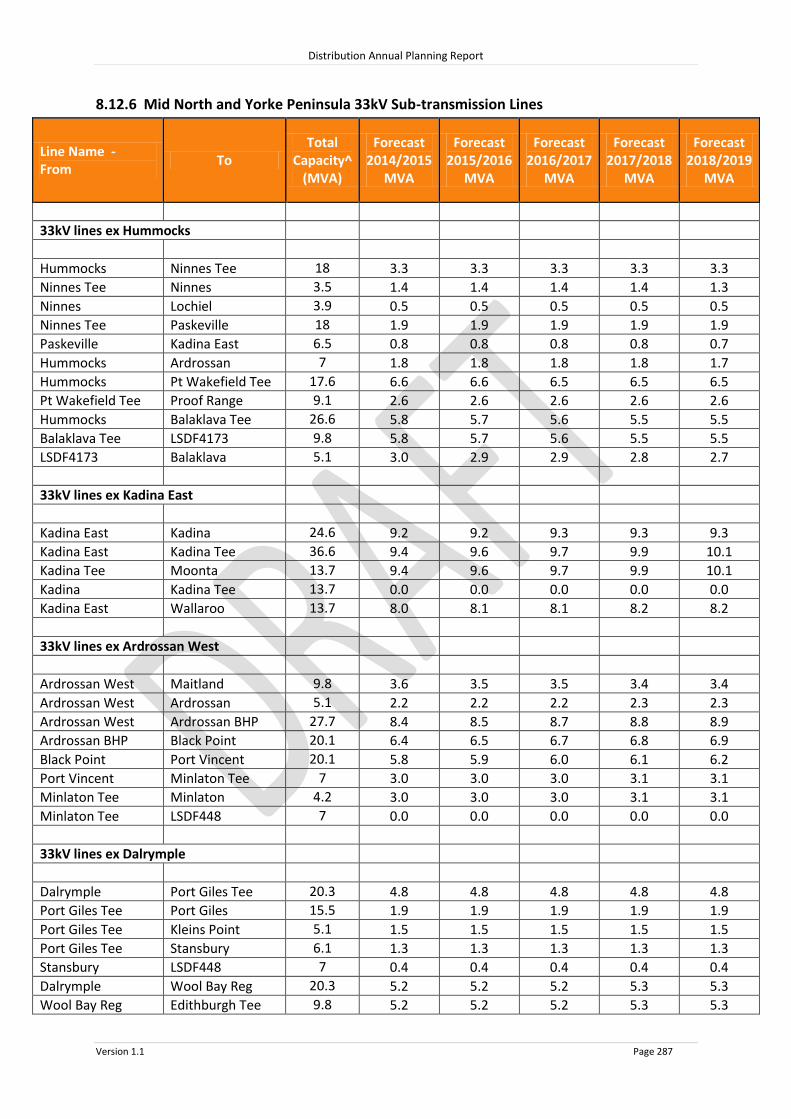
Distribution Annual Planning Report
Version 1.1 Page 287
8.12.6 Mid North and Yorke Peninsula 33kV Sub-transmission Lines
Line Name - From
To Total
Capacity^ (MVA)
Forecast 2014/2015
MVA
Forecast 2015/2016
MVA
Forecast 2016/2017
MVA
Forecast 2017/2018
MVA
Forecast 2018/2019
MVA
33kV lines ex Hummocks
Hummocks Ninnes Tee 18 3.3 3.3 3.3 3.3 3.3
Ninnes Tee Ninnes 3.5 1.4 1.4 1.4 1.4 1.3
Ninnes Lochiel 3.9 0.5 0.5 0.5 0.5 0.5
Ninnes Tee Paskeville 18 1.9 1.9 1.9 1.9 1.9
Paskeville Kadina East 6.5 0.8 0.8 0.8 0.8 0.7
Hummocks Ardrossan 7 1.8 1.8 1.8 1.8 1.7
Hummocks Pt Wakefield Tee 17.6 6.6 6.6 6.5 6.5 6.5
Pt Wakefield Tee Proof Range 9.1 2.6 2.6 2.6 2.6 2.6
Hummocks Balaklava Tee 26.6 5.8 5.7 5.6 5.5 5.5
Balaklava Tee LSDF4173 9.8 5.8 5.7 5.6 5.5 5.5
LSDF4173 Balaklava 5.1 3.0 2.9 2.9 2.8 2.7
33kV lines ex Kadina East
Kadina East Kadina 24.6 9.2 9.2 9.3 9.3 9.3
Kadina East Kadina Tee 36.6 9.4 9.6 9.7 9.9 10.1
Kadina Tee Moonta 13.7 9.4 9.6 9.7 9.9 10.1
Kadina Kadina Tee 13.7 0.0 0.0 0.0 0.0 0.0
Kadina East Wallaroo 13.7 8.0 8.1 8.1 8.2 8.2
33kV lines ex Ardrossan West
Ardrossan West Maitland 9.8 3.6 3.5 3.5 3.4 3.4
Ardrossan West Ardrossan 5.1 2.2 2.2 2.2 2.3 2.3
Ardrossan West Ardrossan BHP 27.7 8.4 8.5 8.7 8.8 8.9
Ardrossan BHP Black Point 20.1 6.4 6.5 6.7 6.8 6.9
Black Point Port Vincent 20.1 5.8 5.9 6.0 6.1 6.2
Port Vincent Minlaton Tee 7 3.0 3.0 3.0 3.1 3.1
Minlaton Tee Minlaton 4.2 3.0 3.0 3.0 3.1 3.1
Minlaton Tee LSDF448 7 0.0 0.0 0.0 0.0 0.0
33kV lines ex Dalrymple
Dalrymple Port Giles Tee 20.3 4.8 4.8 4.8 4.8 4.8
Port Giles Tee Port Giles 15.5 1.9 1.9 1.9 1.9 1.9
Port Giles Tee Kleins Point 5.1 1.5 1.5 1.5 1.5 1.5
Port Giles Tee Stansbury 6.1 1.3 1.3 1.3 1.3 1.3
Stansbury LSDF448 7 0.4 0.4 0.4 0.4 0.4
Dalrymple Wool Bay Reg 20.3 5.2 5.2 5.2 5.3 5.3
Wool Bay Reg Edithburgh Tee 9.8 5.2 5.2 5.2 5.3 5.3

Distribution Annual Planning Report
Version 1.1 Page 288
Line Name - From
To Total
Capacity^ (MVA)
Forecast 2014/2015
MVA
Forecast 2015/2016
MVA
Forecast 2016/2017
MVA
Forecast 2017/2018
MVA
Forecast 2018/2019
MVA
Edithburgh Tee Edithburgh 15.5 1.1 1.1 1.1 1.1 1.0
Edithburgh Tee Yorketown 9.8 4.1 4.2 4.2 4.2 4.2
Yorketown Warooka 5.1 2.5 2.5 2.5 2.5 2.6
Warooka Marion Bay 15.5 0.7 0.7 0.7 0.8 0.8
33kV lines ex Brinkworth
Brinkworth Yacka Tee 6.2 1.8 1.8 1.8 1.8 1.7
Yacka Tee Spalding Tee 5.1 1.8 1.8 1.8 1.8 1.7
Spalding Tee Gladstone 3.9 0.4 0.4 0.4 0.4 0.4
Spalding Tee Spalding 3.1 1.4 1.4 1.4 1.4 1.4
Brinkworth Collinsfield 6.2 0.7 0.7 0.7 0.6 0.6
Brinkworth Brinkworth Tee 6.2 3.7 3.6 3.6 3.5 3.5
Brinkworth Tee Brinkworth Town 5.1 3.7 3.6 3.6 3.5 3.5
Brinkworth Town Blyth 5.1 2.8 2.7 2.7 2.7 2.6
Blyth Balaklava 4 0.5 0.5 0.5 0.5 0.4
Blyth Clare North Tee 6.2 0.1 0.1 0.1 0.1 0.1
33kV lines ex Waterloo
Waterloo Riverton Tee 6.2 6.6 6.5 6.5 6.4 6.3
Riverton Tee Auburn Tee 6.2 4.3 4.3 4.2 4.2 4.1
Auburn Tee Auburn 6.2 3.5 3.4 3.4 3.3 3.3
Auburn Tee Auburn 33/.4 15.5 0.8 0.8 0.8 0.8 0.8
Riverton Tee Riverton 15.5 2.3 2.3 2.2 2.2 2.2
Waterloo Robertstown 7 1.0 1.0 1.0 1.0 0.9
Waterloo Clare Tee 20.3 0.1 0.1 0.1 0.1 0.1
Waterloo Marrabel 7 4.4 4.3 4.3 4.2 4.2
Marrabel Eudunda Tee 7 2.1 2.1 2.1 2.0 2.0
Eudunda Tee Eudunda 5.1 2.1 2.1 2.1 2.0 2.0
33kV lines ex Templers
Templers Wasleys 13 8.7 8.8 8.8 8.9 9.0
Wasleys Mallala 5.1 4.4 4.5 4.6 4.7 4.8
Templers Hamley Bridge 5.1 4.9 4.9 4.8 4.8 4.8
Hamley Bridge Balaklava 5.1 2.2 2.2 2.2 2.2 2.2
Templers Freeling 13.2 8.5 8.5 8.4 8.4 8.3
Freeling Kapunda 7 5.8 5.8 5.8 5.8 5.7
Kapunda Eudunda Tee 7 0.0 0.0 0.0 0.0 0.0
Templers Daveyston 21.4 1.8 1.8 1.8 1.8 1.8
Templers Gawler Belt Tee 20.3 8.4 8.4 8.5 8.5 8.5
Gawler Belt Tee Evanston Tee 6.5 0.0 0.0 0.0 0.0 0.0
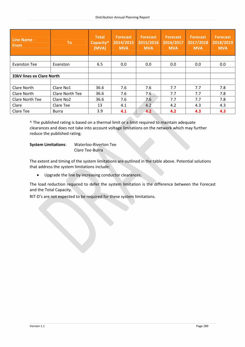
Distribution Annual Planning Report
Version 1.1 Page 289
Line Name - From
To Total
Capacity^ (MVA)
Forecast 2014/2015
MVA
Forecast 2015/2016
MVA
Forecast 2016/2017
MVA
Forecast 2017/2018
MVA
Forecast 2018/2019
MVA
Evanston Tee Evanston 6.5 0.0 0.0 0.0 0.0 0.0
33kV lines ex Clare North
Clare North Clare No1 36.6 7.6 7.6 7.7 7.7 7.8
Clare North Clare North Tee 36.6 7.6 7.6 7.7 7.7 7.8
Clare North Tee Clare No2 36.6 7.6 7.6 7.7 7.7 7.8
Clare Clare Tee 13 4.1 4.2 4.2 4.3 4.3
Clare Tee Burra 3.9 4.1 4.2 4.2 4.3 4.3
^ The published rating is based on a thermal limit or a limit required to maintain adequate clearances and does not take into account voltage limitations on the network which may further reduce the published rating. System Limitations: Waterloo-Riverton Tee Clare Tee-Burra The extent and timing of the system limitations are outlined in the table above. Potential solutions that address the system limitations include:
Upgrade the line by increasing conductor clearances.
The load reduction required to defer the system limitation is the difference between the Forecast and the Total Capacity.
RIT-D’s are not expected to be required for these system limitations.
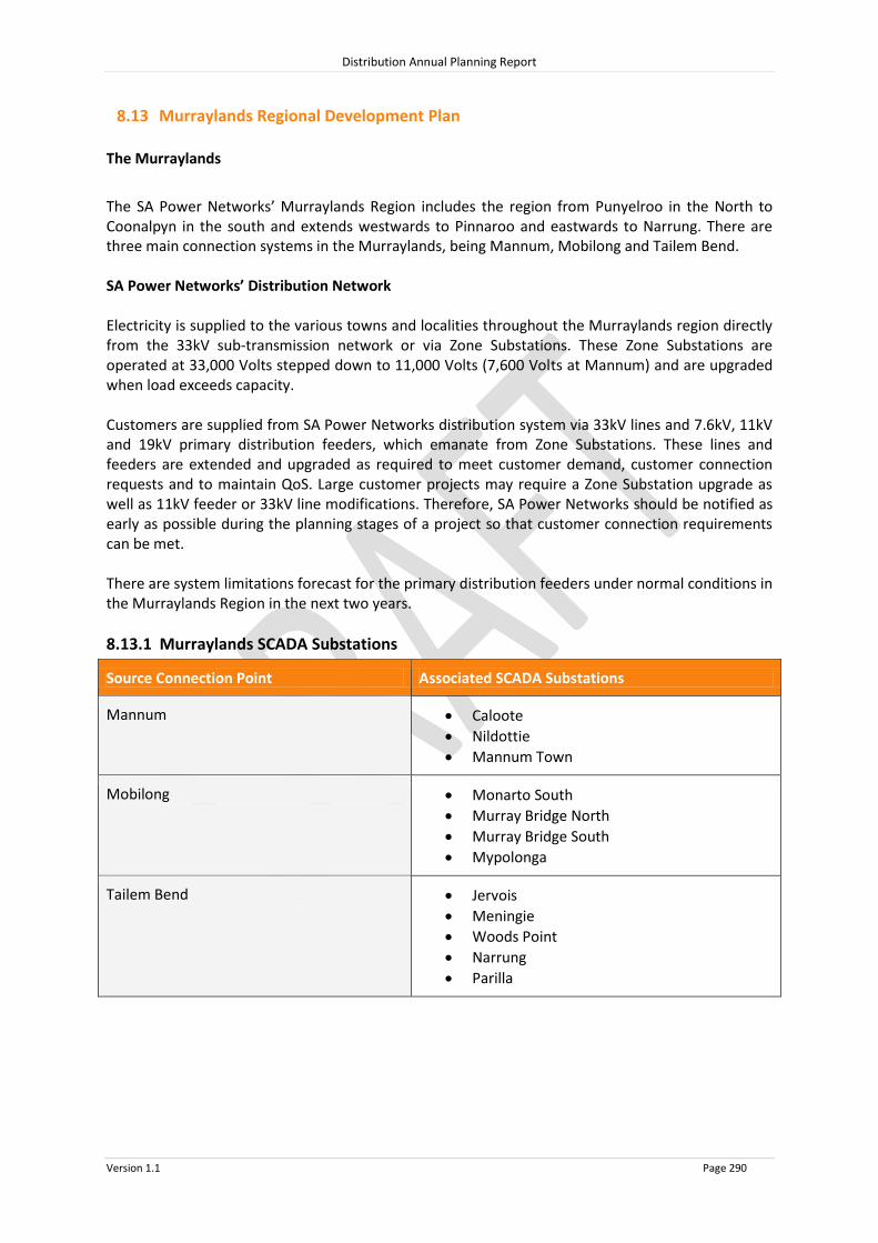
Distribution Annual Planning Report
Version 1.1 Page 290
8.13 Murraylands Regional Development Plan
The Murraylands
The SA Power Networks’ Murraylands Region includes the region from Punyelroo in the North to Coonalpyn in the south and extends westwards to Pinnaroo and eastwards to Narrung. There are three main connection systems in the Murraylands, being Mannum, Mobilong and Tailem Bend. SA Power Networks’ Distribution Network Electricity is supplied to the various towns and localities throughout the Murraylands region directly from the 33kV sub-transmission network or via Zone Substations. These Zone Substations are operated at 33,000 Volts stepped down to 11,000 Volts (7,600 Volts at Mannum) and are upgraded when load exceeds capacity. Customers are supplied from SA Power Networks distribution system via 33kV lines and 7.6kV, 11kV and 19kV primary distribution feeders, which emanate from Zone Substations. These lines and feeders are extended and upgraded as required to meet customer demand, customer connection requests and to maintain QoS. Large customer projects may require a Zone Substation upgrade as well as 11kV feeder or 33kV line modifications. Therefore, SA Power Networks should be notified as early as possible during the planning stages of a project so that customer connection requirements can be met. There are system limitations forecast for the primary distribution feeders under normal conditions in the Murraylands Region in the next two years.
8.13.1 Murraylands SCADA Substations
Source Connection Point Associated SCADA Substations
Mannum Caloote
Nildottie
Mannum Town
Mobilong Monarto South
Murray Bridge North
Murray Bridge South
Mypolonga
Tailem Bend Jervois
Meningie
Woods Point
Narrung
Parilla

MENINGIE
CAMPBELL PARK
NARRUNG
PUNYELROO
WOODS POINT
JERVOIS FLAT 2JERVOIS FLAT 1
TAILEM BEND TOWN
JERVOISTAILEM BEND
BINNIES
COONALPYN
COOMANDOOK
MONARTO SOUTH
MOBILONG
MANNUM
CALOOTE
MURRAY BRIDGE NORTHMURRAY BRIDGE SOUTH
MYPOLONGA
MANNUM TOWN
CAMBRAI
WALKER FLAT
KAROONDA
TEAL FLAT
NILDOTTIE
LAMEROO
PINNAROO
GERANIUM
0 5 10 15 20 25 30
Kilometres
MURRAY LANDS
Legend275kV Transmission Line132kV Transmission Line66kV Sub Transmission Line33kV Sub Transmission LineSubstation
RIVERLAND
System Limitation.

Distribution Annual Planning Report
Version 1.1 Page 292
Substation: Mannum 132/33kV
Region: Murraylands
(ETC) Transmission Category: 4
Number of Transformers: 2
Total Nameplate Rating (MVA): 40 MVA
Actuals
Year 2009/2010 2010/2011 2011/2012 2012/2013 2013/2014
Sum
mer
MW 14.3 10.1 13.3 12.6 12.6
MVAr 6.5 5.0 4.7 4.2 3.9
MVA 15.7 11.2 14.1 13.3 13.2
PF 0.91 0.91 0.94 0.95 0.95
Year 2009 2010 2011 2012 2013
Win
ter MW 7.9 8.3 7.1 8.4 7.5
MVAr 1.6 1.8 2.3 2.4 0.7
MVA 8.1 8.5 7.5 8.7 7.5
PF 0.98 0.98 0.95 0.96 1.00
Forecast
Sum
mer
10% POE Forecast 2014/2015 2015/2016 2016/2017 2017/2018 2018/2019
MW 12.3 12.4 12.5 12.5 12.5
MVAr 4.1 4.2 4.2 4.2 4.2
MVA 13.0 13.1 13.1 13.2 13.2
PF 0.95 0.95 0.95 0.95 0.95
Firm Delivery Capacity (MVA) 21.0 21.0 21.0 21.0 21.0
System Limitation (Y/N) N N N N N
Hrs per annum > 95% of Peak Load (hrs) 1
Year Former Step Change (MVA) Year Future Step Change (10% POE MVA)

Distribution Annual Planning Report
Version 1.1 Page 293
Substation: Mobilong 132/33kV
Region: Murraylands
(ETC) Transmission Category: 4
Number of Transformers: 2
Total Nameplate Rating (MVA): 120 MVA
Actuals
Year 2009/2010 2010/2011 2011/2012 2012/2013 2013/2014
Sum
mer
MW 39.9 41.2 37.3 36.6 41.0
MVAr 16.3 16.9 17.1 12.0 15.3
MVA 43.1 44.6 41.0 38.6 43.8
PF 0.93 0.93 0.91 0.95 0.94
Year 2009 2010 2011 2012 2013
Win
ter MW 30.3 28.9 28.2 28.4 28.1
MVAr 9.2 8.8 7.8 6.9 5.9
MVA 31.6 30.2 29.2 29.3 28.7
PF 0.96 0.96 0.96 0.97 0.98
Forecast
Sum
mer
10% POE Forecast 2014/2015 2015/2016 2016/2017 2017/2018 2018/2019
MW 40.1 40.3 40.3 40.5 40.7
MVAr 16.0 16.0 16.1 16.1 16.2
MVA 43.2 43.3 43.4 43.6 43.8
PF 0.93 0.93 0.93 0.93 0.93
Firm Delivery Capacity (MVA) 57.2 57.2 57.2 57.2 57.2
System Limitation (Y/N) N N N N N
Hrs per annum > 95% of Peak Load (hrs) 11
Year Former Step Change (MVA) Year Future Step Change (10% POE MVA)

Distribution Annual Planning Report
Version 1.1 Page 294
Substation: Tailem Bend 132/33kV
Region: Murraylands
(ETC) Transmission Category: 4
Number of Transformers: 2
Total Nameplate Rating (MVA): 50 MVA
Actuals
Year 2009/2010 2010/2011 2011/2012 2012/2013 2013/2014
Sum
mer
MW 25.3 23.3 19.8 20.4 21.8
MVAr 9.2 7.2 5.4 5.9 5.5
MVA 26.9 24.4 20.6 21.2 22.5
PF 0.94 0.96 0.96 0.96 0.97
Year 2009 2010 2011 2012 2013
Win
ter MW 14.7 15.5 15.4 15.1 15.1
MVAr 0.5 0.2 1.0 0.6 0.1
MVA 14.7 15.5 15.4 15.2 15.1
PF 1.00 1.00 1.00 1.00 1.00
Forecast
Sum
mer
10% POE Forecast 2014/2015 2015/2016 2016/2017 2017/2018 2018/2019
MW 21.3 21.1 20.9 20.7 20.5
MVAr 5.8 5.8 5.7 5.6 5.6
MVA 22.1 21.9 21.7 21.4 21.2
PF 0.96 0.96 0.96 0.96 0.96
Firm Delivery Capacity (MVA) 32.5 32.5 32.5 32.5 32.5
System Limitation (Y/N) N N N N N
Hrs per annum > 95% of Peak Load (hrs) 5
Year Former Step Change (MVA) Year Future Step Change (10% POE MVA)

Distribution Annual Planning Report
Version 1.1 Page 295
Substation: Caloote 33/11kV
Region: Murraylands
Number of Feeders: 1
Number of Transformers: 2
Total Nameplate Rating (MVA): 3 MVA
Actuals
Year 2009/2010 2010/2011 2011/2012 2012/2013 2013/2014
Sum
mer
MW 1.9 2.0 1.8 1.8 1.8
MVAr 0.7 0.8 0.7 0.7 0.9
MVA 2.0 2.2 1.9 2.0 2.0
PF 0.93 0.93 0.93 0.93 0.89
Year 2009 2010 2011 2012 2013
Win
ter MW 1.3 1.3 1.6 1.5 1.5
MVAr 0.5 0.5 0.6 0.6 0.6
MVA 1.4 1.4 1.7 1.6 1.6
PF 0.93 0.93 0.93 0.93 0.93
Forecast
Sum
mer
10% POE Forecast 2014/2015 2015/2016 2016/2017 2017/2018 2018/2019
MW 1.8 1.8 1.8 1.7 1.7
MVAr 0.8 0.8 0.8 0.8 0.7
MVA 1.9 1.9 1.9 1.9 1.9
PF 0.92 0.92 0.92 0.92 0.92
Total Capacity (MVA) 3.9 3.9 3.9 3.9 3.9
50% POE Forecast
MW 1.6 1.6 1.6 1.6 1.6
MVAr 0.7 0.7 0.7 0.7 0.7
MVA 1.8
1.7
1.7
1.7
1.7 PF 0.92 0.92 0.92 0.92 0.92
Firm Delivery Capacity (MVA) 2.3 2.3 2.3 2.3 2.3
Transfer Capacity (MVA) 0.0
0.0
0.0
0.0
0.0 System Limitation (Y/N) N N N N N
Hrs per annum > 95% of Peak Load (hrs) 7
Year Former Step Change (MVA) Year Future Step Change (10% POE MVA)

Distribution Annual Planning Report
Version 1.1 Page 296
Substation: Coonalpyn 33/11kV
Region: Murraylands
Number of Feeders: 1
Number of Transformers: 2
Total Nameplate Rating (MVA): 1 MVA
Actuals
Year 2009/2010 2010/2011 2011/2012 2012/2013 2013/2014
Sum
mer
MW 0.4 0.4 0.4 0.3 0.3
MVAr 0.2 0.2 0.1 0.1 0.1
MVA 0.5 0.5 0.4 0.4 0.4
PF 0.86 0.90 0.93 0.93 0.93
Year 2009 2010 2011 2012 2013
Win
ter MW 0.3 0.3 0.3 0.3 0.3
MVAr 0.1 0.1 0.1 0.1 0.1
MVA 0.4 0.3 0.3 0.3 0.3
PF 0.94 0.97 0.93 0.93 0.92
Forecast
Sum
mer
10% POE Forecast 2014/2015 2015/2016 2016/2017 2017/2018 2018/2019
MW 0.4 0.3 0.3 0.3 0.3
MVAr 0.2 0.2 0.2 0.2 0.2
MVA 0.4 0.4 0.4 0.4 0.4
PF 0.88 0.88 0.88 0.88 0.88
Total Capacity (MVA) 1.3 1.3 1.3 1.3 1.3
50% POE Forecast
MW 0.3 0.3 0.3 0.3 0.3
MVAr 0.2 0.2 0.2 0.2 0.2
MVA 0.3
0.3
0.3
0.3
0.3 PF 0.88 0.88 0.88 0.88 0.88
Firm Delivery Capacity (MVA) 0.8 0.8 0.8 0.8 0.8
Transfer Capacity (MVA) 0.0
0.0
0.0
0.0
0.0 System Limitation (Y/N) N N N N N
Hrs per annum > 95% of Peak Load (hrs) 1
Year Former Step Change (MVA) Year Future Step Change (10% POE MVA)

Distribution Annual Planning Report
Version 1.1 Page 297
Substation: Jervois 33/11kV
Region: Murraylands
Number of Feeders: 2
Number of Transformers: 1
Total Nameplate Rating (MVA): 6.25 MVA
Actuals
Year 2009/2010 2010/2011 2011/2012 2012/2013 2013/2014
Sum
mer
MW 3.0 3.0 2.5 2.6 2.4
MVAr 1.0 1.0 0.9 0.8 0.7
MVA 3.2 3.2 2.7 2.7 2.6
PF 0.95 0.95 0.94 0.95 0.96
Year 2009 2010 2011 2012 2013
Win
ter MW 2.0 2.0 2.0 2.1 2.2
MVAr 0.7 0.7 0.7 0.7 0.5
MVA 2.2 2.2 2.2 2.2 2.2
PF 0.94 0.94 0.94 0.95 0.97
Forecast
Sum
mer
10% POE Forecast 2014/2015 2015/2016 2016/2017 2017/2018 2018/2019
MW 2.4 2.3 2.3 2.3 2.2
MVAr 0.8 0.8 0.7 0.7 0.7
MVA 2.5 2.5 2.4 2.4 2.3
PF 0.95 0.95 0.95 0.95 0.95
Total Capacity (MVA) 8.9 8.9 8.9 8.9 8.9
50% POE Forecast
MW 2.4 2.3 2.3 2.2 2.2
MVAr 0.8 0.7 0.7 0.7 0.7
MVA 2.5
2.4
2.4
2.3
2.3 PF 0.95 0.95 0.95 0.95 0.95
Firm Delivery Capacity (MVA) 0.0 0.0 0.0 0.0 0.0
Transfer Capacity (MVA) 0.5
0.5
0.5
0.5
0.5 System Limitation (Y/N) Y* Y* Y* Y* Y*
Hrs per annum > 95% of Peak Load (hrs) 5
Year Former Step Change (MVA) Year Future Step Change (10% POE MVA)
*Within planning criteria risk

Distribution Annual Planning Report
Version 1.1 Page 298
Substation: Mannum Town 33/7.6kV
Region: Murraylands
Number of Feeders: 2
Number of Transformers: 2
Total Nameplate Rating (MVA): 5 MVA
Actuals
Year 2009/2010 2010/2011 2011/2012 2012/2013 2013/2014
Sum
mer
MW N/A N/A N/A N/A N/A
MVAr N/A N/A N/A N/A N/A
MVA N/A N/A N/A N/A N/A
PF N/A N/A N/A N/A N/A
Year 2009 2009 2010 2011 2012
Win
ter MW N/A N/A N/A N/A N/A
MVAr N/A N/A N/A N/A N/A
MVA N/A N/A N/A N/A N/A
PF N/A N/A N/A N/A N/A
Forecast
Sum
mer
10% POE Forecast 2014/2015 2015/2016 2016/2017 2017/2018 2018/2019
MW 4.1 4.1 4.1 4.1 4.1
MVAr 1.3 1.3 1.3 1.4 1.4
MVA 4.3 4.3 4.3 4.3 4.3
PF 0.95 0.95 0.95 0.95 0.95
Total Capacity (MVA) 6.5 6.5 6.5 6.5 6.5
50% POE Forecast
MW 3.7 3.7 3.7 3.7 3.7
MVAr 1.2 1.2 1.2 1.2 1.2
MVA 3.9
3.9
3.9
3.9
3.9 PF 0.95 0.95 0.95 0.95 0.95
Firm Delivery Capacity (MVA) 3.8 3.8 3.8 3.8 3.8
Transfer Capacity (MVA) 0.0
0.0
0.0
0.0
0.0 System Limitation (Y/N) Y* Y* Y* Y* Y*
Hrs per annum > 95% of Peak Load (hrs) 6
Year Former Step Change (MVA) Year Future Step Change (10% POE MVA)
*Within planning criteria risk

Distribution Annual Planning Report
Version 1.1 Page 299
Substation: Meningie 33/11kV
Region: Murraylands
Number of Feeders: 2
Number of Transformers: 2
Total Nameplate Rating (MVA): 5 MVA
Actuals
Year 2009/2010 2010/2011 2011/2012 2012/2013 2013/2014
Sum
mer
MW 2.3 2.3 2.1 2.1 2.2
MVAr 0.0 0.1 0.3 0.2 0.2
MVA 2.3 2.3 2.1 2.1 2.3
PF 1.00 1.00 0.99 1.00 1.00
Year 2009 2010 2011 2012 2013
Win
ter MW 1.6 1.9 1.9 2.0 2.0
MVAr 0.9 0.7 0.8 0.8 0.3
MVA 1.9 2.0 2.0 2.1 2.0
PF 0.88 0.94 0.91 0.93 0.99
Forecast
Sum
mer
10% POE Forecast 2014/2015 2015/2016 2016/2017 2017/2018 2018/2019
MW 2.1 2.1 2.1 2.1 2.1
MVAr 0.3 0.3 0.3 0.3 0.3
MVA 2.2 2.2 2.1 2.1 2.1
PF 0.99 0.99 0.99 0.99 0.99
Total Capacity (MVA) 6.5 6.5 6.5 6.5 6.5
50% POE Forecast
MW 2.0 2.0 2.0 2.0 2.0
MVAr 0.3 0.3 0.3 0.3 0.3
MVA 2.0
2.0
2.0
2.1
2.1 PF 0.99 0.99 0.99 0.99 0.99
Firm Delivery Capacity (MVA) 3.8 3.8 3.8 3.8 3.8
Transfer Capacity (MVA) 0.0
0.0
0.0
0.0
0.0 System Limitation (Y/N) N N N N N
Hrs per annum > 95% of Peak Load (hrs) 10
Year Former Step Change (MVA) Year Future Step Change (10% POE MVA)

Distribution Annual Planning Report
Version 1.1 Page 300
Substation: Monarto South 33/11kV
Region: Murraylands
Number of Feeders: 2
Number of Transformers: 1
Total Nameplate Rating (MVA): 12.5 MVA
Actuals
Year 2009/2010 2010/2011 2011/2012 2012/2013 2013/2014
Sum
mer
MW 4.7 5.0 4.5 5.0 4.8
MVAr 2.9 3.0 2.8 2.0 2.8
MVA 5.5 5.8 5.3 5.4 5.6
PF 0.85 0.86 0.85 0.93 0.86
Year 2009 2010 2011 2012 2013
Win
ter MW 4.0 4.0 4.1 5.0 4.0
MVAr 2.0 2.0 2.0 2.0 2.0
MVA 4.5 4.5 4.6 5.4 4.5
PF 0.89 0.89 0.90 0.93 0.89
Forecast
Sum
mer
10% POE Forecast 2014/2015 2015/2016 2016/2017 2017/2018 2018/2019
MW 5.0 4.9 4.8 4.7 4.6
MVAr 2.9 2.9 2.8 2.8 2.7
MVA 5.8 5.6 5.5 5.4 5.3
PF 0.86 0.86 0.86 0.86 0.86
Total Capacity (MVA) 14.5 14.5 14.5 14.5 14.5
50% POE Forecast
MW 4.6 4.5 4.4 4.3 4.3
MVAr 2.7 2.7 2.6 2.6 2.5
MVA 5.3
5.2
5.1
5.0
4.9 PF 0.86 0.86 0.86 0.86 0.86
Firm Delivery Capacity (MVA) 0.0 0.0 0.0 0.0 0.0
Transfer Capacity (MVA) 1.8
1.8
1.8
1.9
1.9 System Limitation (Y/N) Y Y Y Y Y
Hrs per annum > 95% of Peak Load (hrs) 6
Year Former Step Change (MVA) Year Future Step Change (10% POE MVA)
2009/10 +0.6MVA Customer load increase

Distribution Annual Planning Report
Version 1.1 Page 301
Monarto South Substation
System Limitation Monarto South 33/11kV Substation has one 12.5MVA 33/11kV transformer and is located approximately 7km west of the rural city of Murray Bridge. In the summer of 2014/15, up to 3.5MVA of customer load is forecasted to be unsupplied during a contingent event after all available load transfers have been implemented. Potential solutions that address the system limitation include:
Upgrade 11kV feeder ties back to Monarto South Substation (preferred option);
Upgrade the Monarto South Substation with a second transformer;
A RIT-D is not expected to be required for this system limitation.

Distribution Annual Planning Report
Version 1.1 Page 302
Substation: Murray Bridge North 33/11kV
Region: Murraylands
Number of Feeders: 3
Number of Transformers: 2
Total Nameplate Rating (MVA): 25 MVA
Actuals
Year 2009/2010 2010/2011 2011/2012 2012/2013 2013/2014
Sum
mer
MW 19.4 19.9 16.7 16.2 17.6
MVAr 2.8 3.2 5.3 4.5 2.5
MVA 19.6 20.1 17.5 16.8 17.8
PF 0.99 0.99 0.95 0.96 0.99
Year 2009 2010 2011 2012 2013
Win
ter MW 12.9 13.7 13.9 13.9 12.5
MVAr 3.1 5.8 2.8 2.1 1.4
MVA 13.2 14.9 14.1 14.0 12.6
PF 0.97 0.92 0.98 0.99 0.99
Forecast
Sum
mer
10% POE Forecast 2014/2015 2015/2016 2016/2017 2017/2018 2018/2019
MW 17.4 17.6 17.8 18.0 18.2
MVAr 3.2 3.2 3.3 3.3 3.3
MVA 17.7 17.9 18.1 18.3 18.5
PF 0.98 0.98 0.98 0.98 0.98
Total Capacity (MVA) 26.0 26.0 26.0 26.0 26.0
50% POE Forecast
MW 15.9 16.0 16.2 16.3 16.5
MVAr 2.9 2.9 3.0 3.0 3.0
MVA 16.1 16.3 16.4 16.6 16.8
PF 0.98 0.98 0.98 0.98 0.98
Firm Delivery Capacity (MVA) 14.8 14.8 14.8 14.8 14.8
Transfer Capacity (MVA) 12.4
12.3
12.1
12.0
11.9 System Limitation (Y/N) N N N N N
Hrs per annum > 95% of Peak Load (hrs) 7
Year Former Step Change (MVA) Year Future Step Change (10% POE MVA)
2009/10 +1.2MVA from Murray Bridge South
2010/11 +0.3MVA Customer load increase
-1.4MVA to Murray Bridge South
2012/13 -1MVA to Murray Bridge South

Distribution Annual Planning Report
Version 1.1 Page 303
Substation: Murray Bridge South 33/11kV
Region: Murraylands
Number of Feeders: 5
Number of Transformers: 2
Total Nameplate Rating (MVA): 25 MVA
Actuals
Year 2009/2010 2010/2011 2011/2012 2012/2013 2013/2014
Sum
mer
MW 12.6 12.2 12.6 14.7 14.7
MVAr 5.6 5.8 5.5 5.4 6.6
MVA 13.8 13.5 13.7 15.7 16.1
PF 0.91 0.90 0.92 0.94 0.91
Year 2009 2010 2011 2012 2013
Win
ter MW 12.0 10.9 11.1 11.7 12.9
MVAr 2.4 1.9 2.1 1.8 1.6
MVA 12.2 11.0 11.3 11.8 12.9
PF 0.98 0.99 0.98 0.99 0.99
Forecast
Sum
mer
10% POE Forecast 2014/2015 2015/2016 2016/2017 2017/2018 2018/2019
MW 14.8 14.7 14.7 14.6 14.6
MVAr 6.1 6.1 6.1 6.1 6.0
MVA 16.0 16.0 15.9 15.8 15.8
PF 0.92 0.92 0.92 0.92 0.92
Total Capacity (MVA) 28.5 28.5 28.5 28.5 28.5
50% POE Forecast
MW 13.0 13.0 12.9 12.8 12.7
MVAr 5.4 5.4 5.3 5.3 5.3
MVA 14.1
14.0
13.9
13.9
13.8 PF 0.92 0.92 0.92 0.92 0.92
Firm Delivery Capacity (MVA) 15.0 15.0 15.0 15.0 15.0
Transfer Capacity (MVA) 4.5
4.5
4.6
4.6
4.7 System Limitation (Y/N) N N N N N
Hrs per annum > 95% of Peak Load (hrs) 6
Year Former Step Change (MVA) Year Future Step Change (10% POE MVA)
2009/10 -1.2MVA to Murray Bridge North
2010/11 +1.4MVA from Murray Bridge North
2011/12 +1.4MVA Customer load increase
2012/13 +1MVA from Murray Bridge North

Distribution Annual Planning Report
Version 1.1 Page 304
Substation: Mypolonga 33/11kV
Region: Murraylands
Number of Feeders: 2
Number of Transformers: 2
Total Nameplate Rating (MVA): 2 MVA
Actuals
Year 2009/2010 2010/2011 2011/2012 2012/2013 2013/2014
Sum
mer
MW N/A N/A N/A 2.2 2.2
MVAr N/A N/A N/A 0.8 0.8
MVA N/A N/A N/A 2.3 2.3
PF N/A N/A N/A 0.93 0.94
Year 2009 2010 2011 2012 2013
Win
ter MW N/A N/A N/A N/A 1.1
MVAr N/A N/A N/A N/A 0.1
MVA N/A N/A N/A N/A 1.1
PF N/A N/A N/A N/A 0.99
Forecast
Sum
mer
10% POE Forecast 2014/2015 2015/2016 2016/2017 2017/2018 2018/2019
MW 2.3 2.3 2.4 2.4 2.5
MVAr 0.8 0.8 0.8 0.8 0.8
MVA 2.4 2.5 2.5 2.6 2.7
PF 0.95 0.95 0.95 0.95 0.95
Total Capacity (MVA) 2.6 2.6 2.6 2.6 2.6
50% POE Forecast
MW 2.1 2.1 2.1 2.2 2.2
MVAr 0.7 0.7 0.7 0.7 0.7
MVA 2.2 2.2 2.3 2.3 2.4
PF 0.95 0.95 0.95 0.95 0.95
Firm Delivery Capacity (MVA) 1.5 1.5 1.5 1.5 1.5
Transfer Capacity (MVA) 0.0
0.0
0.0
0.0
0.0 System Limitation (Y/N) Y* Y* Y* Y* Y*
Hrs per annum > 95% of Peak Load (hrs) 4
Year Former Step Change (MVA) Year Future Step Change (10% POE MVA)
2014/15 +0.1MVA customer load increase
*Within planning criteria risk margin

Distribution Annual Planning Report
Version 1.1 Page 305
Mypolonga 33/11kV Substation
System Limitation
Mypolonga 33/11kV Substation has two 1MVA 33/11kV transformer and is located near the township of Mypolonga.
In the summer of 2018/2019, the substation transformer is forecast to be overloaded by up to 0.1MVA during 10% POE conditions.
Potential solutions that address the system limitation include:
Upgrade the Mypolonga Substation with a larger transformer or a third transformer (preferred option); or
Upgrade the Mypolonga Substation with a third transformer.
A RIT-D is not expected to be required for this system limitation.
.

Distribution Annual Planning Report
Version 1.1 Page 306
Substation: Narrung 33/11kV
Region: Murraylands
Number of Feeders: 3
Number of Transformers: 2
Total Nameplate Rating (MVA): 3 MVA
Actuals
Year 2009/2010 2010/2011 2011/2012 2012/2013 2013/2014
Sum
mer
MW N/A N/A N/A N/A N/A
MVAr N/A N/A N/A N/A N/A
MVA N/A N/A N/A N/A N/A
PF N/A N/A N/A N/A N/A
Year 2009 2010 2011 2012 2013
Win
ter MW N/A N/A N/A N/A N/A
MVAr N/A N/A N/A N/A N/A
MVA N/A N/A N/A N/A N/A
PF N/A N/A N/A N/A N/A
Forecast
Sum
mer
10% POE Forecast 2014/2015 2015/2016 2016/2017 2017/2018 2018/2019
MW 1.6 1.6 1.6 1.6 1.6
MVAr 0.4 0.4 0.4 0.4 0.4
MVA 1.7 1.7 1.6 1.6 1.6
PF 0.97 0.97 0.97 0.97 0.97
Total Capacity (MVA) 3.9 3.9 3.9 3.9 3.9
50% POE Forecast
MW 1.5 1.4 1.4 1.4 1.4
MVAr 0.4 0.4 0.4 0.4 0.4
MVA 1.5
1.5
1.5
1.5
1.4 PF 0.97 0.97 0.97 0.97 0.97
Firm Delivery Capacity (MVA) 2.3 2.3 2.3 2.3 2.3
Transfer Capacity (MVA) 0.4
0.4
0.4
0.4
0.4 System Limitation (Y/N) N N N N N
Hrs per annum > 95% of Peak Load (hrs) 10
Year Former Step Change (MVA) Year Future Step Change (10% POE MVA)
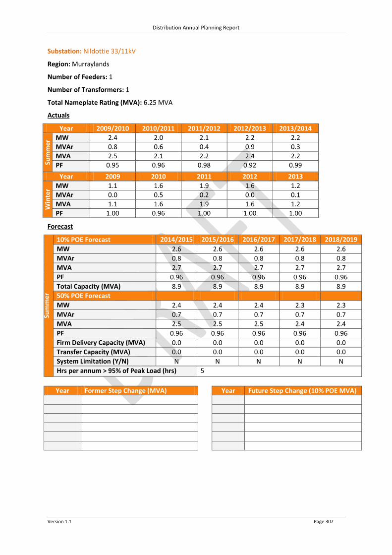
Distribution Annual Planning Report
Version 1.1 Page 307
Substation: Nildottie 33/11kV
Region: Murraylands
Number of Feeders: 1
Number of Transformers: 1
Total Nameplate Rating (MVA): 6.25 MVA
Actuals
Year 2009/2010 2010/2011 2011/2012 2012/2013 2013/2014
Sum
mer
MW 2.4 2.0 2.1 2.2 2.2
MVAr 0.8 0.6 0.4 0.9 0.3
MVA 2.5 2.1 2.2 2.4 2.2
PF 0.95 0.96 0.98 0.92 0.99
Year 2009 2010 2011 2012 2013
Win
ter MW 1.1 1.6 1.9 1.6 1.2
MVAr 0.0 0.5 0.2 0.0 0.1
MVA 1.1 1.6 1.9 1.6 1.2
PF 1.00 0.96 1.00 1.00 1.00
Forecast
Sum
mer
10% POE Forecast 2014/2015 2015/2016 2016/2017 2017/2018 2018/2019
MW 2.6 2.6 2.6 2.6 2.6
MVAr 0.8 0.8 0.8 0.8 0.8
MVA 2.7 2.7 2.7 2.7 2.7
PF 0.96 0.96 0.96 0.96 0.96
Total Capacity (MVA) 8.9 8.9 8.9 8.9 8.9
50% POE Forecast
MW 2.4 2.4 2.4 2.3 2.3
MVAr 0.7 0.7 0.7 0.7 0.7
MVA 2.5
2.5
2.5
2.4
2.4 PF 0.96 0.96 0.96 0.96 0.96
Firm Delivery Capacity (MVA) 0.0 0.0 0.0 0.0 0.0
Transfer Capacity (MVA) 0.0
0.0
0.0
0.0
0.0 System Limitation (Y/N) N N N N N
Hrs per annum > 95% of Peak Load (hrs) 5
Year Former Step Change (MVA) Year Future Step Change (10% POE MVA)

Distribution Annual Planning Report
Version 1.1 Page 308
Substation: Woods Point 33/11kV
Region: Murraylands
Number of Feeders: 3
Number of Transformers: 1
Total Nameplate Rating (MVA): 6.25 MVA
Actuals
Year 2009/2010 2010/2011 2011/2012 2012/2013 2013/2014
Sum
mer
MW 3.0 3.4 3.3 3.1 3.1
MVAr 1.2 1.3 1.3 1.2 1.6
MVA 3.2 3.7 3.6 3.4 3.5
PF 0.93 0.89 0.93 0.93 0.89
Year 2009 2010 2011 2012 2013
Win
ter MW 1.9 2.3 2.2 2.4 2.3
MVAr 0.7 0.9 0.9 1.0 0.9
MVA 2.1 2.4 2.4 2.6 2.5
PF 0.93 0.89 0.93 0.93 0.94
Forecast
Sum
mer
10% POE Forecast 2014/2015 2015/2016 2016/2017 2017/2018 2018/2019
MW 3.0 2.9 2.9 2.8 2.7
MVAr 1.4 1.4 1.4 1.3 1.3
MVA 3.3 3.2 3.2 3.1 3.0
PF 0.90 0.90 0.90 0.90 0.90
Total Capacity (MVA) 8.1 8.1 8.1 8.1 8.1
50% POE Forecast
MW 2.8 2.7 2.7 2.6 2.5
MVAr 1.3 1.3 1.3 1.2 1.2
MVA 3.1
3.0
2.9
2.9
2.8 PF 0.90 0.90 0.90 0.90 0.90
Firm Delivery Capacity (MVA) 0.0 0.0 0.0 0.0 0.0
Transfer Capacity (MVA) 0.8
0.9
0.9
0.9
0.9 System Limitation (Y/N) Y* Y* Y* Y* Y*
Hrs per annum > 95% of Peak Load (hrs) 7
Year Former Step Change (MVA) Year Future Step Change (10% POE MVA)
2010/11 +0.5MVA customer load increase
*Within planning criteria risk margin

Distribution Annual Planning Report
Version 1.1 Page 309
8.13.3 Murraylands Non SCADA Substations 10% POE Forecast
2014/2015 2015/2016 2016/2017 2017/2018 2018/2019
Substation No of
TFs
TF Nameplate
Rating (MVA)
Total Capacity (MVA)
10% POE Forecast (MVA)
10% POE Forecast (MVA)
10% POE Forecast (MVA)
10% POE Forecast (MVA)
10% POE Forecast (MVA)
Belvedere Road 1 0.3 0.4 0.1 0.1 0.1 0.1 0.1
Binnies 2 0.6 0.8 0.3 0.3 0.3 0.3 0.3
Cambrai 2 1.0 1.3 1.0 1.0 1.0 1.0 1.0
Campbell Park 3 1.5 2.0 1.5 1.5 1.4 1.4 1.4
Campbell Pk 33kV PT Reg
5.7 7.4 3.2 3.1 3.1 3.1 3.0
Coomandook 1 0.5 0.7 0.5 0.5 0.5 0.5 0.5
Coonalpyn 33kV Reg 10.0 12.5 6.3 6.2 6.2 6.1 6.1
Geranium 1 0.15 0.2 0.1 0.1 0.1 0.1 0.1
Geranium 33kV Reg 10.0 12.5 5.5 5.4 5.4 5.3 5.2
Jabuk 1 0.2 0.3 0.1 0.1 0.1 0.1 0.1
Karoonda 2 1.0 1.3 0.8 0.8 0.8 0.8 0.8
Ki Ki 1 0.2 0.3 0.1 0.1 0.1 0.1 0.1
Lameroo 2 2.0 2.6 1.3 1.3 1.3 1.3 1.3
Peake 1 0.3 0.4 0.2 0.2 0.2 0.2 0.2
Pellaring Flat 1 0.3 0.4 0.1 0.1 0.1 0.1 0.1

Distribution Annual Planning Report
Version 1.1 Page 310
2014/2015 2015/2016 2016/2017 2017/2018 2018/2019
Substation No of
TFs
TF Nameplate
Rating (MVA)
Total Capacity (MVA)
10% POE Forecast (MVA)
10% POE Forecast (MVA)
10% POE Forecast (MVA)
10% POE Forecast (MVA)
10% POE Forecast (MVA)
Pinnaroo 2 2.0 2.6 1.6 1.6 1.6 1.6 1.6
Pinnaroo South 1 0.3 0.4 0.1 0.1 0.1 0.1 0.1
Punyelroo 1 0.5 0.7 0.5 0.5 0.5 0.5 0.5
Sherlock 1 0.15 0.2 0.03 0.03 0.03 0.03 0.03
Sherlock 33kV Reg 20.0 25.0 7.6 7.5 7.4 7.4 7.3
Tailem Bend Town 2 3.0 3.9 3.2 3.1 3.1 3.1 3.0
Teal Flat 3 3.0 3.9 3.4 3.4 3.5 3.5 3.6
Walker Flat 2 2.0 2.6 1.8 1.8 1.8 1.8 1.9
System Limitations: Nil
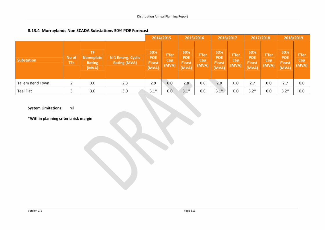
Distribution Annual Planning Report
Version 1.1 Page 311
8.13.4 Murraylands Non SCADA Substations 50% POE Forecast
2014/2015 2015/2016 2016/2017 2017/2018 2018/2019
Substation No of
TFs
TF Nameplate
Rating (MVA)
N-1 Emerg. Cyclic Rating (MVA)
50% POE
F’cast (MVA)
T’fer Cap
(MVA)
50% POE
F’cast (MVA)
T’fer Cap
(MVA)
50% POE
F’cast (MVA)
T’fer Cap
(MVA)
50% POE
F’cast (MVA)
T’fer Cap
(MVA)
50% POE
F’cast (MVA)
T’fer Cap
(MVA)
Tailem Bend Town 2 3.0 2.3 2.9 0.0 2.8 0.0 2.8 0.0 2.7 0.0 2.7 0.0
Teal Flat 3 3.0 3.0 3.1* 0.0 3.1* 0.0 3.1* 0.0 3.2* 0.0 3.2* 0.0
System Limitations: Nil *Within planning criteria risk margin

Distribution Annual Planning Report
Version 1.1 Page 312
8.13.5 Murraylands 33kV Sub-transmission Lines
Line Name - From
To Total
Capacity^ (MVA)
Forecast 2014/2015
MVA
Forecast 2015/2016
MVA
Forecast 2016/2017
MVA
Forecast 2017/2018
MVA
Forecast 2018/2019
MVA
33kV lines ex Mannum
Mannum Mannum Tee 4.2 1.5 1.5 1.5 1.5 1.4
Mannum Tee Cambrai Tee 4.2 1.5 1.5 1.5 1.5 1.4
Cambrai Tee Cambrai 3.9 1.2 1.2 1.2 1.2 1.2
Cambrai Tee Palmer 4.2 0.2 0.2 0.2 0.2 0.2
Palmer Tungkillo 4.2 0.1 0.1 0.1 0.1 0.1
Mannum Teal Flat 9.8 8.5 8.6 8.6 8.7 8.7
Teal Flat Walker Flat 5.1 5.0 5.0 5.0 5.0 5.0
Walker Flat Nildottie 5.1 3.2 3.2 3.2 3.2 3.2
Nildottie Punyelroo 5.1 0.5 0.5 0.5 0.5 0.5
Punyelroo Swan Reach 5.1 0.0 0.0 0.0 0.0 0.0
Mannum Caloote Tee 13.7 6.8 6.7 6.7 6.7 6.7
Caloote Tee Caloote 13.7 1.9 1.9 1.9 1.9 1.9
Caloote Tee Mannum Tee 7.1 4.8 4.8 4.8 4.8 4.9
Mannum Tee Mannum Town 7.1 4.8 4.8 4.8 4.8 4.9
33kV lines ex Mobilong
Mobilong Mobilong Tee 40.4 19.7 19.7 19.8 19.9 19.9
Mobilong Tee Mypolonga Tee 6.5 2.8 2.9 3.0 3.0 3.1
Mypolonga Tee Mypolonga 20.3 2.8 2.9 3.0 3.0 3.1
Mypolonga Tee Caloote 6.5 0.0 0.0 0.0 0.0 0.0
Mobilong Tee M Bridge Nth 21.3 16.8 16.8 16.8 16.8 16.8
Monarto South Tee M Bridge Nth 55 17.6 17.9 18.2 18.4 18.7
M Bridge Nth M B South Tee 21.3 16.0 16.0 16.0 16.0 16.0
M B South Tee M B South 21.3 16.0 16.0 16.0 16.0 16.0
M B South Tee LSDF4636
6.5 0.0 0.0 0.0 0.0 0.0
Mobilong Monarto South Tee 55 23.4 23.6 23.7 23.9 24.1
Monarto South Tee Monarto South 20.3 5.7 5.7 5.6 5.5 5.4
33kV lines ex Tailem Bend
Tailem Bend Tailem Bend Tee 21.4 10.6 10.5 10.3 10.1 10.0
Tailem Bend Tee Tailem Bend Town 21.4 10.6 10.4 10.2 10.0 9.9
Tailem Bend Tee Tailem Bend Pump Stn 5.1 0.1 0.1 0.1 0.1 0.1
Tailem Bend Town Jervois 21.4 7.4 7.3 7.1 7.0 6.8
Jervois Jervois Flat 1 Tee 21.4 4.9 4.8 4.7 4.6 4.5
Jervois Flat 1 Tee Jervois Flat 2 Tee 21.4 3.3 3.2 3.2 3.1 3.0
Jervois Flat 2 Tee Jervois Flat 2 15.5 0.0 0.0 0.0 0.0 0.0
Jervois Flat 2 Tee Woods Point 6.5 3.3 3.2 3.2 3.1 3.0
Woods Point LSDF4636
6.5 0.0 0.0 0.0 0.0 0.0

Distribution Annual Planning Report
Version 1.1 Page 313
Line Name - From
To Total
Capacity^ (MVA)
Forecast 2014/2015
MVA
Forecast 2015/2016
MVA
Forecast 2016/2017
MVA
Forecast 2017/2018
MVA
Forecast 2018/2019
MVA
Tailem Bend Coomandook 18.5 7.2 7.1 7.0 7.0 6.9
Coomandook Coonalpyn 6.7 6.7 6.6 6.6 6.5 6.4
Coonalpyn Binnies 6.2 6.3 6.2 6.2 6.1 6.1
Binnies Meningie 6.2 5.3 5.3 5.2 5.2 5.2
Meningie Campbell Park 6.2 3.2 3.1 3.1 3.1 3.0
Campbell Park Narrung 6.2 1.7 1.7 1.6 1.6 1.6
Tailem Bend Sherlock 6.5 7.6 7.5 7.4 7.3 7.2
Sherlock Karoonda 3.9 0.8 0.8 0.8 0.8 0.8
Sherlock Geranium 5.1 6.4 6.3 6.3 6.2 6.1
Geranium Lameroo 5.1 5.4 5.3 5.3 5.2 5.1
Lameroo Pinnaroo 3.9 3.3 3.2 3.2 3.1 3.1
^ The published rating is based on a thermal limit or a limit required to maintain adequate clearances and does not take into account voltage limitations on the network which may further reduce the published rating. System Limitations: Tailem Bend-Sherlock Sherlock-Geranium Geranium-Lameroo The extent and timing of the system limitations are outlined in the table above. Potential solutions that address the system limitations include:
Upgrade the line by increasing conductor clearances; or
Upgrade the line capacity by replacing the conductor.
The load reduction required to defer the system limitation is the difference between the Forecast and the Total Capacity.
RIT-D’s are not expected to be required for these system limitations.

Distribution Annual Planning Report
Version 1.1 Page 314
8.13.6 Murraylands Primary Distribution Feeders
Murray Bridge North Substation 11kV Feeder Upgrade
System Limitation
The Meatworks 11kV feeder (MB-21) is supplied from the Murray Bridge North 33/11kV Zone Substation and in 2017/2018 will have an N-1 offload capacity of 265A. Meatworks 11kV feeder mainly feeds industrial customers and has a forecast growth rate of 0.9%. Under 50% PoE conditions, the feeder’s N-1 offload capacity will be exceeded in 2017/2018.
Potential solutions that address the system limitation include:
Upgrade the backbone of the Northern Heights 11kV feeder (MB-20) from Murray
Bridge North 33/11kV Zone Substation.
Establish a new 11kV feeder from Murray Bridge North 33/11kV Zone Substation.
Due to the large amount of load at risk, demand side participation is not expected to achieve a large enough reduction of load to defer the constraint on Meatworks 11kV feeder.
A RIT-D is not expected to be required for this system limitation.

Distribution Annual Planning Report
Version 1.1 Page 315
8.14 South East Regional Development Plan
The South East The SA Power Networks’ South East Region includes the region from Tintinara in the North to Port MacDonnell in the south and extends westwards to the coast and eastwards to the Victorian border. There are six main connection systems in the South East, being Keith, Kincraig, Snuggery, Mount Gambier, Blanche and Penola West. A map of this region can be found at the end of this section. SA Power Networks’ Distribution Network Electricity is supplied to the various towns and localities throughout the South East directly from the 33kV sub-transmission network or via Zone Substations. These Zone Substations are operated at 33,000 Volts stepped down to 11,000 Volts (7,600 Volts at Robe) and are upgraded when load exceeds capacity. Customers are supplied from SA Power Networks’ distribution system via 33kV lines and 11kV and 19kV primary distribution feeders. These lines and feeders are extended and upgraded as required to meet customer demand, customer connection requests and to maintain QoS. Large customer projects may require a Zone Substation upgrade as well as 11kV feeder or 33kV line modifications. Therefore, SA Power Networks should be notified as early as possible during the planning stages of a project so that customer connection requirements can be met. There are no system limitations forecast for the primary distribution feeders under normal conditions in the South East Region in the next two years.
8.14.1 South East SCADA Substations
Source Connection Point Associated SCADA Substations
Blanche Allendale East
Mount Gambier North
Mount Gambier West
Keith Bordertown
Keith 11kV
Kincraig Naracoorte
Naracoorte East
Mount Gambier Mount Gambier 11kV
Penola West Coonawarra
Nangwarry
Penola
Snuggery Millicent
Robe

ROBE
BEACHPORT
MILLICENT
CANUNDA WIND FARM
SNUGGERY
LUCINDALE
KINGSTON SOUTH EAST
TINTINARA
KEITH
KONGORONG
MTBURR
ALLENDALE EAST
MOUNT SCHANK
MOUNT GAMBIER- -WEST
BLANCHE
TANTANOOLA
KALANGADOO WEST
GLENCOE
KALANGADOO
PENOLA WEST
LAKESIDE
BLUE LAKE
MOUNT GAMBIER
TARPEENA
NANGWARRY
MOUNTGAMBIER NTH
KINCRAIG
PENOLA
COONAWARRA
PADTHAWAY
NARACOORTE
NARACOORTE EAST
BORDERTOWN
0 10 20 30 40
Kilometres
SOUTH EASTLegend
275kV Transmission Line132kV Transmission Line66kV Sub Transmission Line33kV Sub Transmission LineSubstation
System Limitation.

Distribution Annual Planning Report
Version 1.1 Page 317
Substation: Blanche 132/33kV
Region: South East
(ETC) Transmission Category: 4
Number of Transformers: 2
Total Nameplate Rating (MVA): 110 MVA
Actuals
Year 2009/2010 2010/2011 2011/2012 2012/2013 2013/2014
Sum
mer
MW 35.7 32.6 35.1 32.2 34.0
MVAr 15.4 12.5 14.5 12.7 11.0
MVA 38.9 34.9 37.9 34.7 35.7
PF 0.92 0.93 0.92 0.93 0.95
Year 2009 2010 2011 2012 2013
Win
ter MW 33.9 34.4 34.0 32.7 28.4
MVAr 10.8 9.9 9.8 9.7 7.7
MVA 35.6 35.8 35.4 34.1 29.4
PF 0.95 0.96 0.96 0.96 0.97
Forecast
Sum
mer
10% POE Forecast 2014/2015 2015/2016 2016/2017 2017/2018 2018/2019
MW 32.1 32.4 32.7 33.0 33.3
MVAr 12.1 12.2 12.3 12.4 12.5
MVA 34.3 34.6 35.0 35.3 35.6
PF 0.94 0.94 0.94 0.94 0.94
Firm Delivery Capacity (MVA) 61.5 61.5 61.5 61.5 61.5
System Limitation (Y/N) N N N N N
Hrs per annum > 95% of Peak Load (hrs) 19
Year Former Step Change (MVA) Year Future Step Change (10% POE MVA)
2009/10 +1.0MVA from Mount Gambier
2013/14 +3.9MVA from Mount Gambier

Distribution Annual Planning Report
Version 1.1 Page 318
Substation: Keith 132/33kV
Region: South East
(ETC) Transmission Category: 4
Number of Transformers: 2
Total Nameplate Rating (MVA): 51 MVA
Actuals
Year 2009/2010 2010/2011 2011/2012 2012/2013 2013/2014
Sum
mer
MW 29.5 21.8 20.6 20.9 25.6
MVAr 14.9 7.5 3.2 3.1 6.1
MVA 33.1 23.1 20.8 21.1 26.3
PF 0.89 0.94 0.99 0.99 0.97
Year 2009 2010 2011 2012 2013
Win
ter MW 14.8 14.5 13.3 14.1 13.0
MVAr 2.4 4.1 1.0 2.2 2.1
MVA 15.0 15.0 13.3 14.3 13.2
PF 0.99 0.96 1.00 0.99 0.99
Forecast
Sum
mer
10% POE Forecast 2014/2015 2015/2016 2016/2017 2017/2018 2018/2019
MW 24.8 24.8 25.0 25.0 25.1
MVAr 4.8 4.8 4.9 4.9 4.9
MVA 25.2 25.3 25.4 25.5 25.6
PF 0.98 0.98 0.98 0.98 0.98
Firm Delivery Capacity (MVA) 37.0 37.0 37.0 37.0 37.0
System Limitation (Y/N) N N N N N
Hrs per annum > 95% of Peak Load (hrs) 8
Year Former Step Change (MVA) Year Future Step Change (10% POE MVA)
2011/12 3.0MVAr Capacitor Bank installed
*Potential Impact of below embedded generation has been removed from the Actuals and excluded from the Forecast: (i.e. generation output = 0)
Up to 4MW of diesel export generation at 11kV

Distribution Annual Planning Report
Version 1.1 Page 319
Substation: Kincraig 132/33kV
Region: South East
(ETC) Transmission Category: 4
Number of Transformers: 2
Total Nameplate Rating (MVA): 50 MVA
Actuals
Year 2009/2010 2010/2011 2011/2012 2012/2013 2013/2014
Sum
mer
MW 27.4 24.1 25.9 20.1 21.8
MVAr 15.1 12.8 14.5 8.9 7.9
MVA 31.3 27.3 29.7 22.0 23.2
PF 0.88 0.88 0.87 0.91 0.94
Year 2009 2010 2011 2012 2013
Win
ter MW 19.4 20.1 19.8 18.6 14.3
MVAr 6.4 5.7 6.5 5.1 2.9
MVA 20.4 20.9 20.9 19.2 14.6
PF 0.95 0.96 0.95 0.96 0.98
Forecast
Sum
mer
10% POE Forecast 2014/2015 2015/2016 2016/2017 2017/2018 2018/2019
MW 22.2 22.3 22.4 22.6 22.7
MVAr 9.5 9.6 9.7 9.7 9.8
MVA 24.1 24.3 24.4 24.6 24.7
PF 0.92 0.92 0.92 0.92 0.92
Firm Delivery Capacity (MVA) 30.5 30.5 30.5 30.5 30.5
System Limitation (Y/N) N N N N N
Hrs per annum > 95% of Peak Load (hrs) 3
Year Former Step Change (MVA) Year Future Step Change (10% POE MVA)
2012/13 -8.1MVA to Penola West

Distribution Annual Planning Report
Version 1.1 Page 320
Substation: Mount Gambier 132/33kV
Region: South East
(ETC) Transmission Category: 4
Number of Transformers: 2
Total Nameplate Rating (MVA): 66.1 MVA
Actuals
Year 2009/2010 2010/2011 2011/2012 2012/2013 2013/2014
Sum
mer
MW 28.3 27.3 26.9 25.2 22.4
MVAr 11.6 7.8 9.7 8.7 6.1
MVA 30.6 28.4 28.6 26.7 23.2
PF 0.92 0.96 0.94 0.95 0.96
Year 2009 2010 2011 2012 2013
Win
ter MW 29.9 27.7 29.2 28.2 26.4
MVAr 9.0 19.2 7.8 7.5 4.6
MVA 31.2 33.7 30.2 29.2 26.8
PF 0.96 0.82 0.97 0.97 0.99
Forecast
Sum
mer
10% POE Forecast 2014/2015 2015/2016 2016/2017 2017/2018 2018/2019
MW 21.3 21.1 20.8 20.5 20.3
MVAr 6.3 6.2 6.1 6.1 6.0
MVA 22.2 22.0 21.7 21.4 21.2
PF 0.96 0.96 0.96 0.96 0.96
Firm Delivery Capacity (MVA) 32.5 32.5 32.5 32.5 32.5
System Limitation (Y/N) N N N N N
Hrs per annum > 95% of Peak Load (hrs) 13
Year Former Step Change (MVA) Year Future Step Change (10% POE MVA)
2009/10 -1.0MVA to Blanche
-2.0MVA Customer load decrease
2012/13 -5.3MVA to Penola West
2013/14 -3.9MVA to Blanche
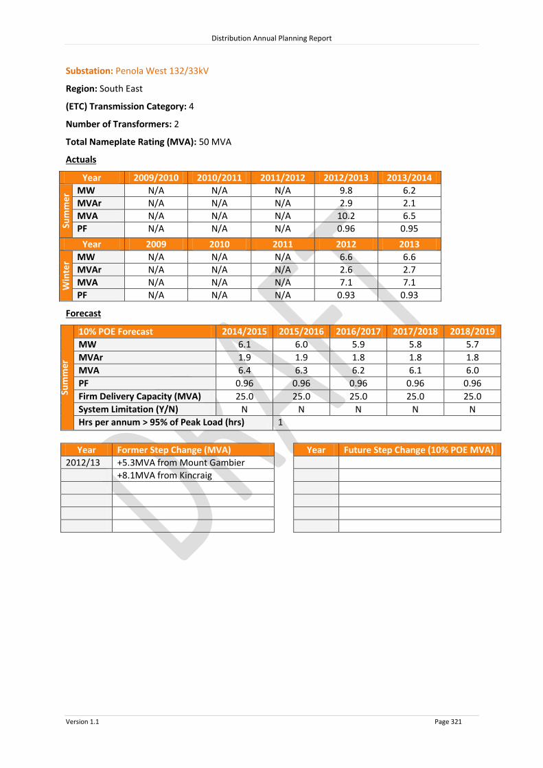
Distribution Annual Planning Report
Version 1.1 Page 321
Substation: Penola West 132/33kV
Region: South East
(ETC) Transmission Category: 4
Number of Transformers: 2
Total Nameplate Rating (MVA): 50 MVA
Actuals
Year 2009/2010 2010/2011 2011/2012 2012/2013 2013/2014
Sum
mer
MW N/A N/A N/A 9.8 6.2
MVAr N/A N/A N/A 2.9 2.1
MVA N/A N/A N/A 10.2 6.5
PF N/A N/A N/A 0.96 0.95
Year 2009 2010 2011 2012 2013
Win
ter MW N/A N/A N/A 6.6 6.6
MVAr N/A N/A N/A 2.6 2.7
MVA N/A N/A N/A 7.1 7.1
PF N/A N/A N/A 0.93 0.93
Forecast
Sum
mer
10% POE Forecast 2014/2015 2015/2016 2016/2017 2017/2018 2018/2019
MW 6.1 6.0 5.9 5.8 5.7
MVAr 1.9 1.9 1.8 1.8 1.8
MVA 6.4 6.3 6.2 6.1 6.0
PF 0.96 0.96 0.96 0.96 0.96
Firm Delivery Capacity (MVA) 25.0 25.0 25.0 25.0 25.0
System Limitation (Y/N) N N N N N
Hrs per annum > 95% of Peak Load (hrs) 1
Year Former Step Change (MVA) Year Future Step Change (10% POE MVA)
2012/13 +5.3MVA from Mount Gambier
+8.1MVA from Kincraig

Distribution Annual Planning Report
Version 1.1 Page 322
Substation: Snuggery Rural 132/33kV
Region: South East
(ETC) Transmission Category: 3
Number of Transformers: 1
Total Nameplate Rating (MVA): 25 MVA
Actuals
Year 2009/2010 2010/2011 2011/2012 2012/2013 2013/2014
Sum
mer
MW 16.2 12.2 13.8 14.1 15.7
MVAr 6.9 5.5 5.5 5.8 6.6
MVA 17.6 13.4 14.8 15.2 17.0
PF 0.92 0.91 0.93 0.92 0.92
Year 2009 2010 2011 2012 2013
Win
ter MW 13.3 13.4 13.0 13.2 12.3
MVAr 3.0 3.1 2.7 2.6 3.9
MVA 13.7 13.7 13.3 13.5 12.9
PF 0.98 0.97 0.98 0.98 0.95
Forecast
Sum
mer
10% POE Forecast 2014/2015 2015/2016 2016/2017 2017/2018 2018/2019
MW 15.8 15.9 16.1 16.2 16.3
MVAr 6.4 6.5 6.5 6.6 6.6
MVA 17.1 17.2 17.3 17.5 17.6
PF 0.93 0.93 0.93 0.93 0.93
Firm Delivery Capacity (MVA) 28.8 28.8 28.8 28.8 28.8
System Limitation (Y/N) N N N N N
Hrs per annum > 95% of Peak Load (hrs) 4
Year Former Step Change (MVA) Year Future Step Change (10% POE MVA)

Distribution Annual Planning Report
Version 1.1 Page 323
Substation: Allendale East 33/11kV
Region: South East
Number of Feeders: 2
Number of Transformers: 2
Total Nameplate Rating (MVA): 5 MVA
Actuals
Year 2009/2010 2010/2011 2011/2012 2012/2013 2013/2014
Sum
mer
MW 4.3 4.3 4.3 4.2 4.1
MVAr 2.1 2.1 2.1 2.1 2.0
MVA 4.8 4.8 4.8 4.7 4.6
PF 0.90 0.90 0.90 0.90 0.90
Year 2009 2010 2011 2012 2013
Win
ter MW 3.1 3.1 3.2 3.1 2.9
MVAr 1.5 1.5 1.6 1.5 1.4
MVA 3.5 3.5 3.6 3.4 3.3
PF 0.90 0.90 0.90 0.90 0.90
Forecast
Sum
mer
10% POE Forecast 2014/2015 2015/2016 2016/2017 2017/2018 2018/2019
MW 4.0 4.0 4.0 4.0 4.0
MVAr 1.9 1.9 1.9 1.9 1.9
MVA 4.5 4.5 4.5 4.4 4.4
PF 0.90 0.90 0.90 0.90 0.90
Total Capacity (MVA) 6.8 6.8 6.8 6.8 6.8
50% POE Forecast
MW 3.7 3.7 3.7 3.7 3.7
MVAr 1.8 1.8 1.8 1.8 1.8
MVA 4.1
4.1
4.1
4.1
4.1 PF 0.90 0.90 0.90 0.90 0.90
Firm Delivery Capacity (MVA) 3.8 3.8 3.8 3.8 3.8
Transfer Capacity (MVA) 0.0
0.0
0.0
0.0
0.0 System Limitation (Y/N) Y* Y* Y* Y* Y*
Hrs per annum > 95% of Peak Load (hrs) 7
Year Former Step Change (MVA) Year Future Step Change (10% POE MVA)
*Within planning criteria risk margin
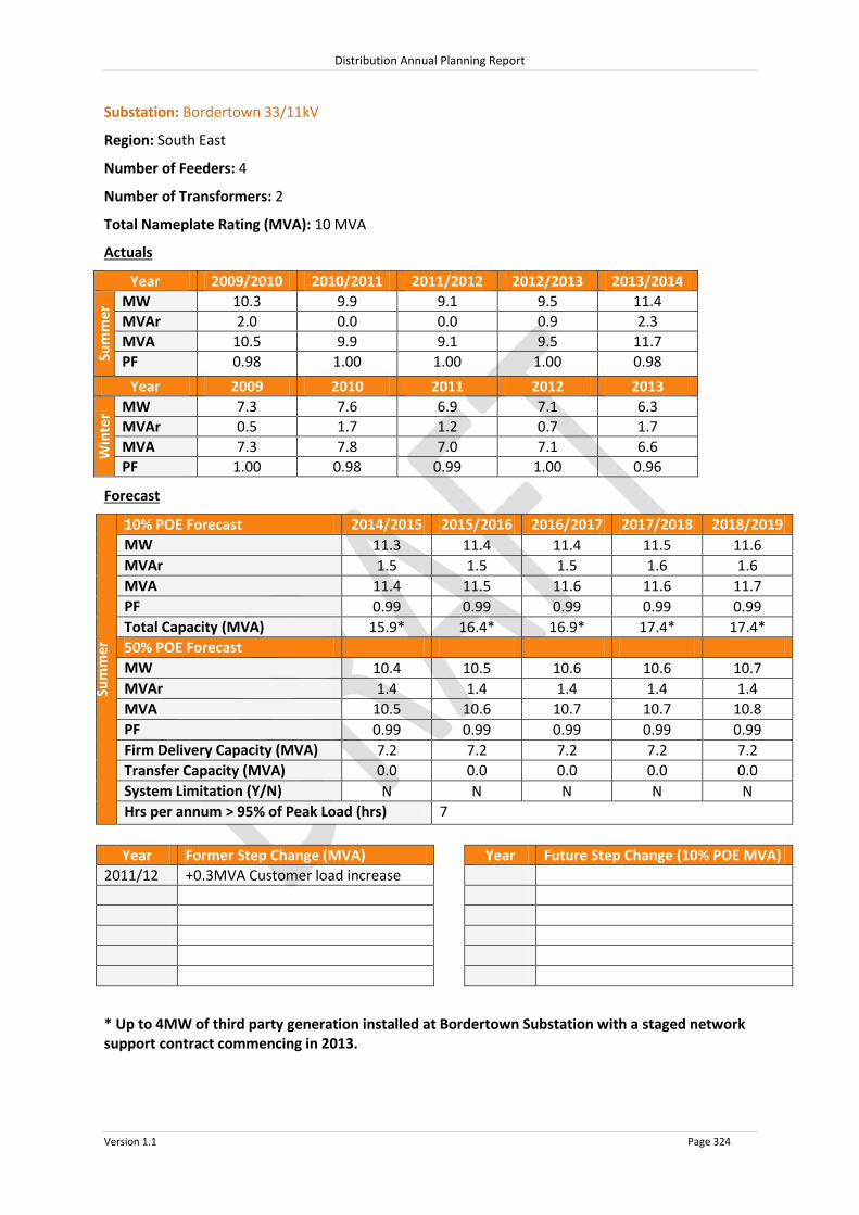
Distribution Annual Planning Report
Version 1.1 Page 324
Substation: Bordertown 33/11kV
Region: South East
Number of Feeders: 4
Number of Transformers: 2
Total Nameplate Rating (MVA): 10 MVA
Actuals
Year 2009/2010 2010/2011 2011/2012 2012/2013 2013/2014
Sum
mer
MW 10.3 9.9 9.1 9.5 11.4
MVAr 2.0 0.0 0.0 0.9 2.3
MVA 10.5 9.9 9.1 9.5 11.7
PF 0.98 1.00 1.00 1.00 0.98
Year 2009 2010 2011 2012 2013
Win
ter MW 7.3 7.6 6.9 7.1 6.3
MVAr 0.5 1.7 1.2 0.7 1.7
MVA 7.3 7.8 7.0 7.1 6.6
PF 1.00 0.98 0.99 1.00 0.96
Forecast
Sum
mer
10% POE Forecast 2014/2015 2015/2016 2016/2017 2017/2018 2018/2019
MW 11.3 11.4 11.4 11.5 11.6
MVAr 1.5 1.5 1.5 1.6 1.6
MVA 11.4 11.5 11.6 11.6 11.7
PF 0.99 0.99 0.99 0.99 0.99
Total Capacity (MVA) 15.9* 16.4* 16.9* 17.4* 17.4*
50% POE Forecast
MW 10.4 10.5 10.6 10.6 10.7
MVAr 1.4 1.4 1.4 1.4 1.4
MVA 10.5
10.6
10.7
10.7
10.8 PF 0.99 0.99 0.99 0.99 0.99
Firm Delivery Capacity (MVA) 7.2 7.2 7.2 7.2 7.2
Transfer Capacity (MVA) 0.0
0.0
0.0
0.0
0.0 System Limitation (Y/N) N N N N N
Hrs per annum > 95% of Peak Load (hrs) 7
Year Former Step Change (MVA) Year Future Step Change (10% POE MVA)
2011/12 +0.3MVA Customer load increase
* Up to 4MW of third party generation installed at Bordertown Substation with a staged network support contract commencing in 2013.

Distribution Annual Planning Report
Version 1.1 Page 325
Substation: Coonawara 33/11kV
Region: South East
Number of Feeders: 2
Number of Transformers: 2
Total Nameplate Rating (MVA): 10 MVA
Actuals
Year 2009/2010 2010/2011 2011/2012 2012/2013 2013/2014
Sum
mer
MW 3.0 2.6 3.1 3.9 2.7
MVAr 2.0 2.3 2.4 2.1 1.2
MVA 3.6 3.5 3.9 4.4 3.0
PF 0.83 0.75 0.80 0.88 0.92
Year 2009 2010 2011 2012 2013
Win
ter MW 8.0 5.6 2.4 1.5 1.5
MVAr 4.1 2.3 0.0 1.3 1.3
MVA 9.0 6.0 2.4 2.0 2.0
PF 0.89 0.93 1.00 0.76 0.75
Forecast
Sum
mer
10% POE Forecast 2014/2015 2015/2016 2016/2017 2017/2018 2018/2019
MW 3.2 3.1 3.1 3.0 3.0
MVAr 1.6 1.5 1.5 1.5 1.5
MVA 3.5 3.5 3.4 3.4 3.3
PF 0.90 0.90 0.90 0.90 0.90
Total Capacity (MVA) 13.5 13.5 13.5 13.5 13.5
50% POE Forecast
MW 3.1 3.1 3.0 3.0 3.0
MVAr 1.5 1.5 1.5 1.5 1.4
MVA 3.5
3.4
3.4
3.3
3.3 PF 0.90 0.90 0.90 0.90 0.90
Firm Delivery Capacity (MVA) 7.2 7.2 7.2 7.2 7.2
Transfer Capacity (MVA) 0.7
0.7
0.7
0.7
0.7 System Limitation (Y/N) N N N N N
Hrs per annum > 95% of Peak Load (hrs) 7
Year Former Step Change (MVA) Year Future Step Change (10% POE MVA)

Distribution Annual Planning Report
Version 1.1 Page 326
Substation: Keith 33/11kV
Region: South East
Number of Feeders: 3
Number of Transformers: 2
Total Nameplate Rating (MVA): 12.5 MVA
Actuals
Year 2009/2010 2010/2011 2011/2012 2012/2013 2013/2014
Sum
mer
MW 5.6 5.3 5.0 5.1 5.9
MVAr 3.1 2.6 0.0 0.3 0.3
MVA 6.4 5.9 5.0 5.2 5.9
PF 0.87 0.90 1.00 1.00 1.00
Year 2009 2010 2011 2012 2013
Win
ter MW 3.4 3.3 3.0 2.8 3.0
MVAr 1.9 1.4 1.1 0.3 0.2
MVA 3.9 3.6 3.2 2.8 3.0
PF 0.87 0.91 0.94 0.99 1.00
Forecast
Sum
mer
10% POE Forecast 2014/2015 2015/2016 2016/2017 2017/2018 2018/2019
MW 5.8 5.8 5.8 5.8 5.8
MVAr 0.3 0.3 0.3 0.3 0.3
MVA 5.8 5.8 5.8 5.8 5.8
PF 1.00 1.00 1.00 1.00 1.00
Total Capacity (MVA) 16.6 16.6 16.6 16.6 16.6
50% POE Forecast
MW 5.2 5.2 5.2 5.2 5.2
MVAr 0.2 0.2 0.2 0.2 0.2
MVA 5.2 5.2 5.2 5.2 5.3
PF 1.00 1.00 1.00 1.00 1.00
Firm Delivery Capacity (MVA) 8.8 8.8 8.8 8.8 8.8
Transfer Capacity (MVA) 0.0
0.0
0.0
0.0
0.0 System Limitation (Y/N) N N N N N
Hrs per annum > 95% of Peak Load (hrs) 7
Year Former Step Change (MVA) Year Future Step Change (10% POE MVA)
2011/12 3.0MVAr Capacitor Bank installed

Distribution Annual Planning Report
Version 1.1 Page 327
Substation: Millicent 33/11kV
Region: South East
Number of Feeders: 3
Number of Transformers: 2
Total Nameplate Rating (MVA): 10 MVA
Actuals
Year 2009/2010 2010/2011 2011/2012 2012/2013 2013/2014
Sum
mer
MW 6.6 5.6 5.6 5.7 6.4
MVAr 2.9 2.4 2.4 2.8 2.7
MVA 7.2 6.1 6.1 6.4 7.0
PF 0.92 0.92 0.92 0.90 0.92
Year 2009 2010 2011 2012 2013
Win
ter MW 6.4 6.8 6.5 6.7 6.5
MVAr 0.9 2.2 2.0 1.5 1.5
MVA 6.5 7.1 6.8 6.8 6.6
PF 0.99 0.95 0.96 0.98 0.98
Forecast
Sum
mer
10% POE Forecast 2014/2015 2015/2016 2016/2017 2017/2018 2018/2019
MW 5.6 5.5 5.5 5.4 5.4
MVAr 2.3 2.3 2.3 2.3 2.2
MVA 6.0 6.0 5.9 5.9 5.9
PF 0.92 0.92 0.92 0.92 0.92
Total Capacity (MVA) 13.2 13.2 13.2 13.2 13.2
50% POE Forecast
MW 5.1 5.0 4.9 4.9 4.8
MVAr 2.1 2.1 2.0 2.0 2.0
MVA 5.5
5.4
5.3
5.3
5.2 PF 0.92 0.92 0.92 0.92 0.92
Firm Delivery Capacity (MVA) 7.1 7.1 7.1 7.1 7.1
Transfer Capacity (MVA) 0.0
0.0
0.0
0.0
0.0 System Limitation (Y/N) N N N N N
Hrs per annum > 95% of Peak Load (hrs) 6
Year Former Step Change (MVA) Year Future Step Change (10% POE MVA)

Distribution Annual Planning Report
Version 1.1 Page 328
Substation: Mount Gambier 33/11kV
Region: South East
Number of Feeders: 4
Number of Transformers: 2
Total Nameplate Rating (MVA): 20 MVA
Actuals
Year 2009/2010 2010/2011 2011/2012 2012/2013 2013/2014
Sum
mer
MW 17.7 15.9 16.7 18.8 15.7
MVAr 5.2 2.5 4.1 3.8 2.2
MVA 18.5 16.1 17.2 19.2 15.8
PF 0.96 0.99 0.97 0.98 0.99
Year 2009 2010 2011 2012 2013
Win
ter MW 17.6 18.1 17.6 17.2 17.3
MVAr 2.5 4.5 1.9 1.7 1.1
MVA 17.8 18.6 17.7 17.3 17.3
PF 0.99 0.97 0.99 1.00 1.00
Forecast
Sum
mer
10% POE Forecast 2014/2015 2015/2016 2016/2017 2017/2018 2018/2019
MW 14.2 14.0 13.7 13.5 13.3
MVAr 3.0 2.9 2.9 2.8 2.8
MVA 14.5 14.3 14.0 13.8 13.6
PF 0.98 0.98 0.98 0.98 0.98
Total Capacity (MVA) 25.4 25.4 25.4 25.4 25.4
50% POE Forecast
MW 13.3 12.9 12.6 12.3 12.0
MVAr 2.8 2.7 2.6 2.6 2.5
MVA 13.6 13.2 12.8 12.5 12.2
PF 0.98 0.98 0.98 0.98 0.98
Firm Delivery Capacity (MVA) 15.0 15.0 15.0 15.0 15.0
Transfer Capacity (MVA) 9.3
9.4
9.6
9.7
9.9 System Limitation (Y/N) N N N N N
Hrs per annum > 95% of Peak Load (hrs) 7
Year Former Step Change (MVA) Year Future Step Change (10% POE MVA)
2009/10 -1.0MVA to Mount Gambier West
2011/12 +3.4MVA Customer load increase
2013/14 -3.9MVA to Mount Gambier North

Distribution Annual Planning Report
Version 1.1 Page 329
Substation: Mount Gambier North 33/11kV
Region: South East
Number of Feeders: 3
Number of Transformers: 1
Total Nameplate Rating (MVA): 12.5 MVA
Actuals
Year 2009/2010 2010/2011 2011/2012 2012/2013 2013/2014
Sum
mer
MW N/A N/A N/A N/A 8.7
MVAr N/A N/A N/A N/A 3.8
MVA N/A N/A N/A N/A 9.5
PF N/A N/A N/A N/A 0.92
Year 2009 2010 2011 2012 2013
Win
ter MW N/A N/A N/A N/A N/A
MVAr N/A N/A N/A N/A N/A
MVA N/A N/A N/A N/A N/A
PF N/A N/A N/A N/A N/A
Forecast
Sum
mer
10% POE Forecast 2014/2015 2015/2016 2016/2017 2017/2018 2018/2019
MW 8.8 8.8 8.9 8.9 9.0
MVAr 3.8 3.9 3.9 3.9 4.0
MVA 9.6 9.6 9.7 9.8 9.8
PF 0.92 0.92 0.92 0.92 0.92
Total Capacity (MVA) 17.0 17.0 17.0 17.0 17.0
50% POE Forecast
MW 7.9 7.9 8.0 8.1 8.1
MVAr 3.5 3.5 3.5 3.5 3.6
MVA 8.6
8.7
8.7
8.8
8.9 PF 0.92 0.92 0.92 0.92 0.92
Firm Delivery Capacity (MVA) 0.0 0.0 0.0 0.0 0.0
Transfer Capacity (MVA) 8.1
8.1
8.0
8.0
7.9 System Limitation (Y/N) Y* Y* Y* Y* Y*
Hrs per annum > 95% of Peak Load (hrs) 7
Year Former Step Change (MVA) Year Future Step Change (10% POE MVA)
2013/14 +3.9MVA from Mount Gambier
+3.4MVA from Mount Gambier West
*Within planning criteria risk margin

Distribution Annual Planning Report
Version 1.1 Page 330
Substation: Mount Gambier West 33/11kV
Region: South East
Number of Feeders: 5
Number of Transformers: 2
Total Nameplate Rating (MVA): 20 MVA
Actuals
Year 2009/2010 2010/2011 2011/2012 2012/2013 2013/2014
Sum
mer
MW 21.9 19.6 21.3 21.9 15.5
MVAr 8.3 6.7 7.6 6.7 3.9
MVA 23.4 20.7 22.6 22.9 16.0
PF 0.94 0.95 0.94 0.96 0.97
Year 2009 2010 2011 2012 2013
Win
ter MW 20.1 20.9 20.3 19.9 19.6
MVAr 4.5 5.3 4.0 3.5 3.7
MVA 20.6 21.6 20.7 20.2 19.9
PF 0.98 0.97 0.98 0.99 0.98
Forecast
Sum
mer
10% POE Forecast 2014/2015 2015/2016 2016/2017 2017/2018 2018/2019
MW 15.7 15.9 16.0 16.2 16.4
MVAr 4.9 4.9 5.0 5.0 5.1
MVA 16.4 16.6 16.8 17.0 17.1
PF 0.96 0.96 0.96 0.96 0.96
Total Capacity (MVA) 25.6 25.6 25.6 25.6 25.6
50% POE Forecast
MW 15.4 15.4 15.5 15.5 15.5
MVAr 4.8 4.8 4.8 4.8 4.8
MVA 16.1 16.1 16.2 16.2 16.3
PF 0.96 0.96 0.96 0.96 0.96
Firm Delivery Capacity (MVA) 15.0 15.0 15.0 15.0 15.0
Transfer Capacity (MVA) 16.2
16.2
16.1
16.1
16.0 System Limitation (Y/N) N N N N N
Hrs per annum > 95% of Peak Load (hrs) 9
Year Former Step Change (MVA) Year Future Step Change (10% POE MVA)
2009/10 +1.0MVA from Mount Gambier
2012/13 +0.7MVA Customer load increase
2013/14 -3.4MVA to Mount Gambier North

Distribution Annual Planning Report
Version 1.1 Page 331
Substation: Nangwarry 33/11kV
Region: South East
Number of Feeders: 1
Number of Transformers: 1
Total Nameplate Rating (MVA): 3 MVA
Actuals
Year 2009/2010 2010/2011 2011/2012 2012/2013 2013/2014
Sum
mer
MW N/A N/A N/A 1.0 1.0
MVAr N/A N/A N/A 0.6 0.3
MVA N/A N/A N/A 1.1 1.0
PF N/A N/A N/A 0.87 0.95
Year 2009 2010 2011 2012 2013
Win
ter MW N/A N/A N/A 1.0 1.1
MVAr N/A N/A N/A 0.5 0.4
MVA N/A N/A N/A 1.1 1.1
PF N/A N/A N/A 0.91 0.94
Forecast
Sum
mer
10% POE Forecast 2014/2015 2015/2016 2016/2017 2017/2018 2018/2019
MW 1.0 0.9 0.9 0.8 0.8
MVAr 0.3 0.3 0.3 0.3 0.3
MVA 1.0 1.0 0.9 0.9 0.9
PF 0.94 0.94 0.94 0.94 0.94
Total Capacity (MVA) 3.9 3.9 3.9 3.9 3.9
50% POE Forecast
MW 1.0 1.0 1.0 0.9 0.9
MVAr 0.4 0.4 0.4 0.3 0.3
MVA 1.1
1.1
1.0
1.0
1.0 PF 0.94 0.94 0.94 0.94 0.94
Firm Delivery Capacity (MVA) 0.0 0.0 0.0 0.0 0.0
Transfer Capacity (MVA) 0.0
0.0
0.0
0.0
0.0 System Limitation (Y/N) Y* Y* Y* Y* Y*
Hrs per annum > 95% of Peak Load (hrs) 7
Year Former Step Change (MVA) Year Future Step Change (10% POE MVA)
*Within planning criteria risk margin

Distribution Annual Planning Report
Version 1.1 Page 332
Substation: Naracoorte 33/11kV
Region: South East
Number of Feeders: 4
Number of Transformers: 2
Total Nameplate Rating (MVA): 25 MVA
Actuals
Year 2009/2010 2010/2011 2011/2012 2012/2013 2013/2014
Sum
mer
MW 15.8 14.5 15.8 14.6 10.8
MVAr 8.4 8.1 8.2 7.1 4.5
MVA 17.9 16.6 17.8 16.2 11.7
PF 0.88 0.87 0.89 0.90 0.92
Year 2009 2010 2011 2012 2013
Win
ter MW 11.4 11.8 11.3 10.9 10.5
MVAr 4.6 4.5 4.9 4.1 2.9
MVA 12.3 12.6 12.3 11.6 10.9
PF 0.93 0.94 0.92 0.94 0.96
Forecast
Sum
mer
10% POE Forecast 2014/2015 2015/2016 2016/2017 2017/2018 2018/2019
MW 11.0 11.0 11.0 11.0 11.0
MVAr 5.2 5.2 5.2 5.2 5.2
MVA 12.2 12.2 12.2 12.2 12.2
PF 0.90 0.90 0.90 0.90 0.90
Total Capacity (MVA) 27.8 27.8 27.8 27.8 27.8
50% POE Forecast
MW 9.9 9.9 9.9 9.9 9.9
MVAr 4.7 4.7 4.7 4.7 4.7
MVA 11.0
11.0
11.0
11.0
11.0 PF 0.90 0.90 0.90 0.90 0.90
Firm Delivery Capacity (MVA) 14.8 14.8 14.8 14.8 14.8
Transfer Capacity (MVA) 4.5
4.5
4.4
4.4
4.4 System Limitation (Y/N) N N N N N
Hrs per annum > 95% of Peak Load (hrs) 7
Year Former Step Change (MVA) Year Future Step Change (10% POE MVA)
2013/14 -7.1MVA to Naracoorte East

Distribution Annual Planning Report
Version 1.1 Page 333
Substation: Naracoorte East 33/11kV
Region: South East
Number of Feeders: 3
Number of Transformers: 1
Total Nameplate Rating (MVA): 12.5 MVA
Actuals
Year 2009/2010 2010/2011 2011/2012 2012/2013 2013/2014
Sum
mer
MW N/A N/A N/A N/A 5.2
MVAr N/A N/A N/A N/A 2.8
MVA N/A N/A N/A N/A 5.9
PF N/A N/A N/A N/A 0.88
Year 2009 2010 2011 2012 2013
Win
ter MW N/A N/A N/A N/A 3.4
MVAr N/A N/A N/A N/A 1.8
MVA N/A N/A N/A N/A 3.8
PF N/A N/A N/A N/A 0.89
Forecast
Sum
mer
10% POE Forecast 2014/2015 2015/2016 2016/2017 2017/2018 2018/2019
MW 5.2 5.2 5.3 5.3 5.3
MVAr 2.8 2.8 2.8 2.8 2.8
MVA 5.9 5.9 6.0 6.0 6.0
PF 0.88 0.88 0.88 0.88 0.88
Total Capacity (MVA) 17.2 17.2 17.2 17.2 17.2
50% POE Forecast
MW 4.7 4.7 4.7 4.7 4.7
MVAr 2.5 2.5 2.5 2.5 2.5
MVA 5.3
5.4
5.4
5.4
5.4 PF 0.88 0.88 0.88 0.88 0.88
Firm Delivery Capacity (MVA) 0.0 0.0 0.0 0.0 0.0
Transfer Capacity (MVA) 7.4
7.4
7.4
7.4
7.4 System Limitation (Y/N) N N N N N
Hrs per annum > 95% of Peak Load (hrs) 6
Year Former Step Change (MVA) Year Future Step Change (10% POE MVA)
2013/14 +7.1MVA from Naracoorte

Distribution Annual Planning Report
Version 1.1 Page 334
Substation: Penola 33/11kV
Region: South East
Number of Feeders: 2
Number of Transformers: 2
Total Nameplate Rating (MVA): 3 MVA
Actuals
Year 2009/2010 2010/2011 2011/2012 2012/2013 2013/2014
Sum
mer
MW N/A N/A N/A 2.7 2.7
MVAr N/A N/A N/A 1.3 1.1
MVA N/A N/A N/A 3.0 2.9
PF N/A N/A N/A 0.90 0.92
Year 2009 2010 2011 2012 2013
Win
ter MW N/A N/A N/A 2.2 2.2
MVAr N/A N/A N/A 0.7 0.6
MVA N/A N/A N/A 2.3 2.3
PF N/A N/A N/A 0.96 0.97
Forecast
Sum
mer
10% POE Forecast 2014/2015 2015/2016 2016/2017 2017/2018 2018/2019
MW 2.6 2.6 2.6 2.6 2.6
MVAr 1.1 1.1 1.1 1.1 1.1
MVA 2.8 2.8 2.8 2.8 2.8
PF 0.92 0.92 0.92 0.92 0.92
Total Capacity (MVA) 3.9 3.9 3.9 3.9 3.9
50% POE Forecast
MW 2.6 2.6 2.6 2.6 2.6
MVAr 1.1 1.1 1.1 1.1 1.1
MVA 2.8
2.8
2.8
2.8
2.8 PF 0.92 0.92 0.92 0.92 0.92
Firm Delivery Capacity (MVA) 2.3 2.3 2.3 2.3 2.3
Transfer Capacity (MVA) 0.7
0.7
0.7
0.7
0.7 System Limitation (Y/N) N N N N N
Hrs per annum > 95% of Peak Load (hrs) 7
Year Former Step Change (MVA) Year Future Step Change (10% POE MVA)

Distribution Annual Planning Report
Version 1.1 Page 335
Substation: Robe 33/7.6kV
Region: South East
Number of Feeders: 2
Number of Transformers: 2
Total Nameplate Rating (MVA): 5 MVA
Actuals
Year 2009/2010 2010/2011 2011/2012 2012/2013 2013/2014
Sum
mer
MW 3.5 3.2 3.6 3.5 3.9
MVAr 1.0 0.9 1.1 0.7 1.1
MVA 3.7 3.3 3.8 3.5 4.1
PF 0.96 0.96 0.96 0.98 0.96
Year 2009 2010 2011 2012 2013
Win
ter MW 2.5 2.3 2.8 2.8 2.4
MVAr 0.7 0.7 0.8 0.6 0.5
MVA 2.6 2.4 2.9 2.9 2.5
PF 0.96 0.96 0.96 0.98 0.98
Forecast
Sum
mer
10% POE Forecast 2014/2015 2015/2016 2016/2017 2017/2018 2018/2019
MW 3.3 3.4 3.4 3.4 3.4
MVAr 0.9 0.9 0.9 0.9 0.9
MVA 3.4 3.5 3.5 3.5 3.6
PF 0.97 0.97 0.97 0.97 0.97
Total Capacity (MVA) 6.5 6.5 6.5 6.5 6.5
50% POE Forecast
MW 2.9 3.0 3.0 3.0 3.1
MVAr 0.8 0.8 0.8 0.8 0.8
MVA 3.0
3.1
3.1
3.1
3.2 PF 0.97 0.97 0.97 0.97 0.97
Firm Delivery Capacity (MVA) 3.8 3.8 3.8 3.8 3.8
Transfer Capacity (MVA) 0.0
0.0
0.0
0.0
0.0 System Limitation (Y/N) N N N N N
Hrs per annum > 95% of Peak Load (hrs) 7
Year Former Step Change (MVA) Year Future Step Change (10% POE MVA)

Distribution Annual Planning Report
Version 1.1 Page 336
8.14.3 South East Non SCADA Substations 10% POE Forecast
2014/2015 2015/2016 2016/2017 2017/2018 2018/2019
Substation No of
TFs
TF Nameplate
Rating (MVA)
Total Capacity (MVA)
10% POE Forecast (MVA)
10% POE Forecast (MVA)
10% POE Forecast (MVA)
10% POE Forecast (MVA)
10% POE Forecast (MVA)
Beachport 1 2.5 2.7 1.2 1.2 1.2 1.2 1.3
Desert Camp 1 0.5 0.7 0.1 0.1 0.1 0.1 0.1
Glencoe 2 1.0 1.3 1.3 1.3 1.3 1.4 1.4
Hatherleigh 1 0.3 0.4 0.1 0.1 0.1 0.1 0.1
Hatherleigh Regulator 10.0 12.5 6.5 6.7 6.9 7.0 7.2
Inverness 1 1.0 1.3 1.0 1.0 1.0 1.0 1.0
Kalangadoo West 2 1.0 1.3 1.1 1.1 1.1 1.1 1.1
Kalangadoo 1 0.5 0.7 0.6 0.6 0.6 0.6 0.6
Kingston 2 3.0 3.9 3.9 3.9 4.0 4.0 4.0
Kingston PT Reg 33kV
11.4 14.9 4.9 4.9 5.0 5.0 5.0
Kongorong 2 1.0 1.3 1.0 1.0 1.0 1.0 1.0
Kumorna 1 1.0 1.3 0.6 0.6 0.6 0.6 0.6
Lucindale 2 3.0 3.9 1.6 1.6 1.6 1.6 1.6
Mount Burr 1 0.3 0.4 0.4 0.4 0.4 0.4 0.4
Mount Schank 3 3.0 3.9 3.6 3.6 3.7 3.8 3.9

Distribution Annual Planning Report
Version 1.1 Page 337
2014/2015 2015/2016 2016/2017 2017/2018 2018/2019
Substation No of
TFs
TF Nameplate
Rating (MVA)
Total Capacity (MVA)
10% POE Forecast (MVA)
10% POE Forecast (MVA)
10% POE Forecast (MVA)
10% POE Forecast (MVA)
10% POE Forecast (MVA)
Padthaway 2 10.0 13.8 4.9 4.8 4.8 4.8 4.7
Robe 33kV PT Reg 5.7 7.4 4.5 4.5 4.5 4.5 4.6
South End 2 0.6 0.8 0.5 0.6 0.6 0.6 0.6
Tantanoola 1 1.0 1.3 0.8 0.8 0.8 0.8 0.8
Tarpeena 2 10.0 9.5 4.6 4.6 4.5 4.5 4.5
Tintinara 2 1.0 1.3 1.2 1.2 1.2 1.2 1.2
Wirrega 33kV Reg 20.0 25.0 12.6 12.7 12.8 12.8 12.9
System Limitations: Kingston
Glencoe Mount Burr
The extent and timing of the system limitations are outlined in the table above. Potential solutions that address the system limitations include:
Upgrade the Zone Substation by increasing the capacity; or
Power factor correction to reduce the load at the Zone Substation.
The load reduction required to defer the system limitation is the difference between the Forecast and the Total Capacity.
RIT-D’s are not expected to be required for these system limitations.

Distribution Annual Planning Report
Version 1.1 Page 338
8.14.4 South East Non SCADA Substations 50% POE Forecast
2014/2015 2015/2016 2016/2017 2017/2018 2018/2019
Substation No of
TFs
TF Nameplate
Rating (MVA)
N-1 Emerg. Cyclic Rating (MVA)
50% POE
F’cast (MVA)
T’fer Cap
(MVA)
50% POE
F’cast (MVA)
T’fer Cap
(MVA)
50% POE
F’cast (MVA)
T’fer Cap
(MVA)
50% POE
F’cast (MVA)
T’fer Cap
(MVA)
50% POE
F’cast (MVA)
T’fer Cap
(MVA)
Kingston 2 3.0 2.3 3.5 0.0 3.5 0.0 3.6 0.0 3.6 0.0 3.6 0.0
Mount Schank 3 3.0 3.0 3.2 0.1 3.3 0.1 3.3 0.1 3.4 0.1 3.5 0.1
Padthaway 2 10.0 7.4 4.4 0.0 4.3 0.0 4.3 0.0 4.3 0.0 4.3 0.0
Tarpeena 2 10.0 5.0 4.1 0.0 4.1 0.0 4.1 0.0 4.0 0.0 4.0 0.0
System Limitations: Nil

Distribution Annual Planning Report
Version 1.1 Page 339
8.14.5 South East 33kV Sub-transmission Lines
Line Name - From To Total
Capacity^ (MVA)
Forecast 2014/2015
MVA
Forecast 2015/2016
MVA
Forecast 2016/2017
MVA
Forecast 2017/2018
MVA
Forecast 2018/2019
MVA
33kV lines ex Keith
Keith Tintinara 5.1 1.8 1.8 1.8 1.8 1.8
Tintinara Coonalpyn 5.1 0.1 0.1 0.1 0.1 0.1
Keith Padthaway 7 5.2 5.1 5.1 5.0 5.0
Keith Bordertown 17# 15.7 15.2 14.8 14.3 13.9 # Up to 4MW of third party generation installed at Bordertown Substation with a network support contract commencing in 2013.
33kV lines ex Snuggery
Snuggery Millicent 20.3 12.9 12.9 12.9 12.9 12.9
Millicent Hatherleigh 12.7 6.8 6.9 6.9 6.9 7.0
Hatherleigh Beachport Tee 13 6.2 6.2 6.2 6.3 6.3
Beachport Tee Beachport 3.9 1.6 1.7 1.7 1.7 1.7
Beachport Tee Robe 5.1 4.5 4.6 4.6 4.6 4.6
Snuggery APM Tee 1 40.5 7.7 7.7 7.7 7.7 7.7
APM Tee 1 KCA 1 36.6 7.7 7.7 7.7 7.7 7.7
APM Tee 1 Apcel Pulp Mill 40.5 0.0 0.0 0.0 0.0 0.0
Snuggery APM Tee 2 36.6 10.6 10.6 10.6 10.6 10.6
APM Tee 2 Apcel Pulp Mill 36.6 2.9 2.9 2.9 2.9 2.9
APM Tee 2 KCA 2 36.6 7.7 7.7 7.7 7.7 7.7
Snuggery Apcel 40.5 10.6 10.6 10.6 10.6 10.6
Apcel KCA 3 36.6 7.7 7.7 7.7 7.7 7.7
Snuggery Woakwine Mill 7 1.0 1.0 1.0 1.0 1.0
Snuggery Mt Burr 27.7 2.2 2.2 2.2 2.2 2.2
Mt Burr Kalangadoo 6.2 1.7 1.7 1.7 1.7 1.7
33kV lines ex Blanche
Blanche # Mt Gambier West 25.1 17.0 17.2 17.4 17.5 17.7
Mt Gambier West # Blue Lake Tee 0 0.6 0.6 0.6 0.6 0.6
Blue Lake Tee # Mt Gambier Term. 0 0.0 0.0 0.0 0.0 0.0
Blanche # Lakeside Tee 54.6 16.9 16.9 17.0 17.0 17.1
Lakeside Tee # Lakeside 54.6 4.3 4.3 4.2 4.2 4.1
Lakeside Tee # Glencoe Tee 54.6 12.6 12.7 12.8 12.9 12.9
Glencoe Tee Glencoe 7 2.3 2.3 2.4 2.4 2.4
Glencoe Tantanoola 7 1.0 1.0 1.0 1.0 1.0
Tantanoola Apcel 7 0.2 0.2 0.2 0.2 0.2
Glencoe Tee # Mt Gambier Nth 27.7 9.6 9.6 9.7 9.8 9.8
Mt Gambier Nth # Mt Gambier Term. 27.7 0.0 0.0 0.0 0.0 0.0
Blanche Kongorong Tee 15 9.8 9.9 10.0 10.1 10.2
Kongorong Tee Kongorong 5.1 1.0 1.0 1.0 1.0 1.0
Kongorong Tee Mt Schank 12.7 8.9 8.9 9.0 9.1 9.2
Mt Schank Allendale East 5.1 4.5 4.4 4.4 4.4 4.4

Distribution Annual Planning Report
Version 1.1 Page 340
Line Name - From To Total
Capacity^ (MVA)
Forecast 2014/2015
MVA
Forecast 2015/2016
MVA
Forecast 2016/2017
MVA
Forecast 2017/2018
MVA
Forecast 2018/2019
MVA
# = Industrial Weathered Line
33kV lines ex Mt Gambier
Mt Gambier Term. Tarpeena 17.4 4.9 4.9 4.8 4.8 4.8
Tarpeena Nangwarry 7 0.0 0.0 0.0 0.0 0.0
Mt Gambier Term. # CHH 20.3 4.6 4.6 4.6 4.6 4.6
Mt Gambier Term. # Mt G City 33/11 No 1 27.7 7.3 7.2 7.1 7.1 7.0
Mt Gambier Term. # Mt G City 33/11 No 2 27.7 7.3 7.2 7.1 7.1 7.0
# = Industrial Weathered Line
33kV lines ex Kincraig
Kincraig Lucindale 6.2 6.4 6.5 6.6 6.6 6.7
Lucindale Kingston 5.1 3.9 3.9 4.0 4.0 4.0
Kincraig Naracoorte 30 19.5 19.5 19.6 19.6 19.6
Naracoorte Naracoorte East Tee 7 5.9 5.9 6.0 6.0 6.0
Naracoorte East Tee Naracoorte East 27.7 5.9 5.9 6.0 6.0 6.0
Naracoorte East Tee Padthaway 7 0.0 0.0 0.0 0.0 0.0
Kincraig Inverness 27.7 1.0 1.0 1.0 1.0 1.0
Inverness Coonawarra 27.7 0.0 0.0 0.0 0.0 0.0
33kV lines ex Penola West
Penola West 1 Penola Tee 20.3 6.4 6.3 6.2 6.2 6.1
Penola Tee Penola 6.2 6.4 6.3 6.2 6.2 6.1
Penola Coonawarra 6.7 3.5 3.5 3.4 3.4 3.3
Penola West 2 Penola Tee 20.3 3.6 3.5 3.4 3.4 3.3
Penola Tee SAFRIES 6.2 2.5 2.5 2.5 2.4 2.4
Penola Tee Kalangadoo Tee 6.2 1.0 1.0 0.9 0.9 0.9
Kalangadoo Tee Nangwarry 6.2 1.0 1.0 0.9 0.9 0.9
Nangwarry Tarpeena 7 0.0 0.0 0.0 0.0 0.0
^ The published rating is based on a thermal limit or a limit required to maintain adequate clearances and does not take into account voltage limitations on the network which may further reduce the published rating. System Limitations: Mt Gambier West-Blue Lake Tee Penola Tee-Penola The extent and timing of the system limitations are outlined in the table above. Potential solutions that address the system limitations include:
Upgrade the line by increasing conductor clearances; or

Distribution Annual Planning Report
Version 1.1 Page 341
Power factor correction to reduce the load on the line.
The load reduction required to defer the system limitation is the difference between the Forecast and the Total Capacity.
RIT-D’s are not expected to be required for these system limitations.

Distribution Annual Planning Report
Version 1.1 Page 342
8.15 Fleurieu Peninsula Regional Development Plan
The Fleurieu Peninsula
The SA Power Networks’ Fleurieu Peninsula Region includes the region South of Willunga extending south-east to Goolwa, south-west to Cape Jervis, and further south-west to Kangaroo Island. The Fleurieu Peninsula is supplied via the Southern Suburbs meshed network. SA Power Networks’ Distribution Network Electricity is supplied to the various towns and localities throughout the Fleurieu Peninsula via Zone Substations. These Zone Substations are operated at either 66,000 Volts stepped down to 11,000 Volts or 33,000 Volts stepped down to 11,000 Volts. Customers are supplied from SA Power Networks distribution system via 11kV and 19kV primary distribution feeders, which are connected to Zone substations. These feeders are extended and upgraded as required to meet customer demand and customer connection requests. Large customer projects may require a distribution substation upgrade as well as feeder modifications, therefore SA Power Networks should be notified as early as possible during the planning stages of a project so that customer connection requirements can be met. There are no system limitations forecast for the primary distribution feeders under normal conditions in the Fleurieu Peninsula in the next two years.
8.15.1 Fleurieu Peninsula SCADA Substations
Source Connection Point Associated SCADA Substations
Southern Suburbs Meshed 66kV Network (Refer to 8.6 Southern Suburbs Regional Development Plan)
American River
Cape Jervis 33kV
Cape Jervis 11kV
Goolwa
Kingscote
MacGillivray
Myponga
Penneshaw
Square Water Hole
Victor Harbor
Yankalilla 33kV
Yankalilla 11kV
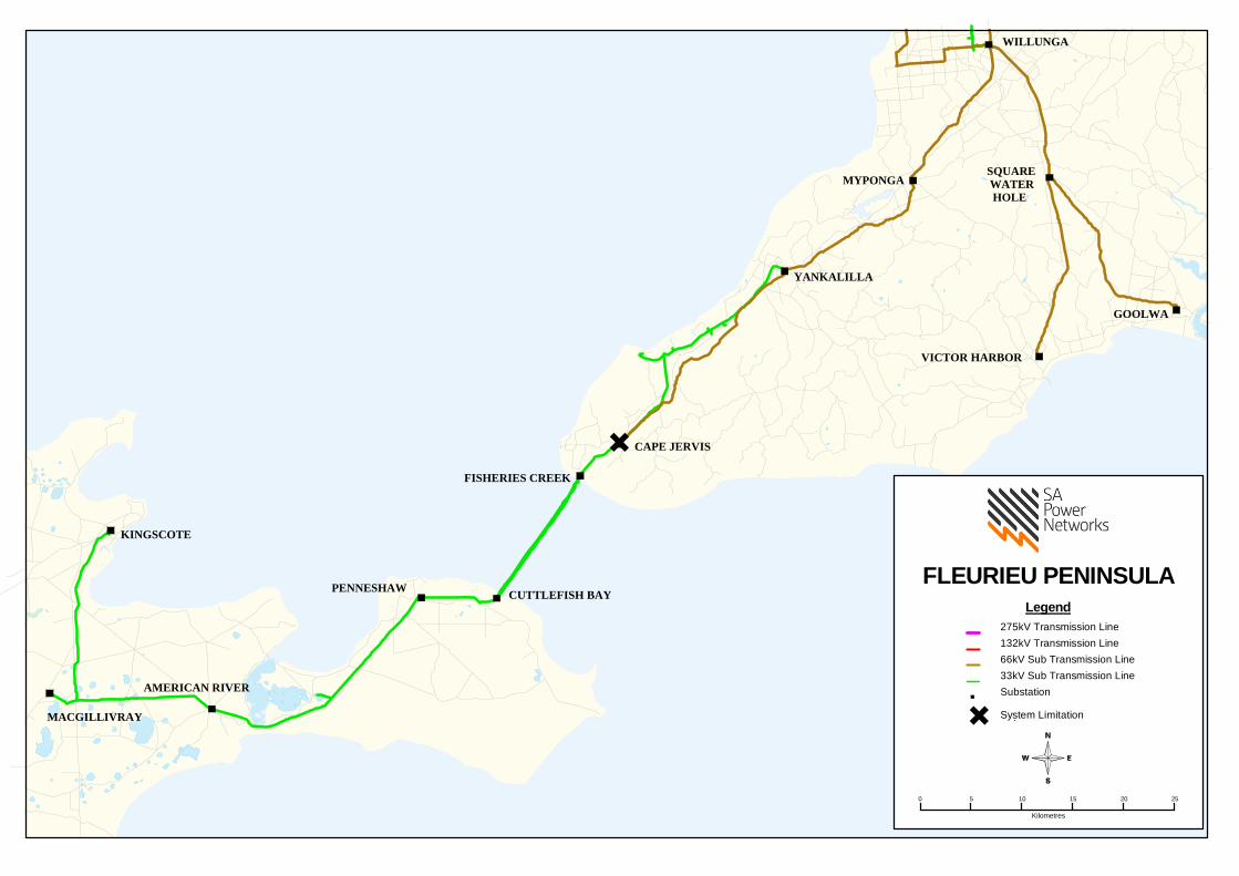
AMERICAN RIVER
KINGSCOTE
PENNESHAW
YANKALILLA
FISHERIES CREEK
GOOLWA
CAPE JERVIS
MYPONGA
VICTOR HARBOR
SQUARE WATER HOLE
WILLUNGA
MACGILLIVRAY
CUTTLEFISH BAYFLEURIEU PENINSULA
Legend275kV Transmission Line132kV Transmission Line66kV Sub Transmission Line33kV Sub Transmission LineSubstation
System Limitation.
0 5 10 15 20 25
Kilometres

Distribution Annual Planning Report
Version 1.1 Page 344
Substation: American River 33/11kV
Region: Fleurieu Peninsula
Number of Feeders: 2
Number of Transformers: 1
Total Nameplate Rating (MVA): 3 MVA
Actuals
Year 2009/2010 2010/2011 2011/2012 2012/2013 2013/2014
Sum
mer
MW 0.6 0.5 0.5 0.5 0.5
MVAr 0.2 0.2 0.2 0.2 0.1
MVA 0.6 0.5 0.5 0.5 0.5
PF 0.93 0.93 0.93 0.93 0.95
Year 2009 2010 2011 2012 2013
Win
ter MW 0.4 0.5 0.4 0.5 0.4
MVAr 0.2 0.2 0.2 0.2 0.1
MVA 0.4 0.5 0.5 0.5 0.4
PF 0.93 0.93 0.93 0.93 0.99
Forecast
Sum
mer
10% POE Forecast 2014/2015 2015/2016 2016/2017 2017/2018 2018/2019
MW 0.4 0.4 0.4 0.4 0.4
MVAr 0.2 0.2 0.2 0.2 0.2
MVA 0.4 0.4 0.4 0.4 0.4
PF 0.92 0.92 0.92 0.92 0.92
Total Capacity (MVA) 3.9 3.9 3.9 3.9 3.9
50% POE Forecast
MW 0.3 0.3 0.3 0.3 0.3
MVAr 0.2 0.2 0.1 0.1 0.1
MVA 0.4
0.4
0.4
0.4
0.4 PF 0.92 0.92 0.92 0.92 0.92
Firm Delivery Capacity (MVA) 0.0 0.0 0.0 0.0 0.0
Transfer Capacity (MVA) 0.0
0.0
0.0
0.0
0.0 System Limitation (Y/N) Y* Y* Y* Y* Y*
Hrs per annum > 95% of Peak Load (hrs) 5
Year Former Step Change (MVA) Year Future Step Change (10% POE MVA)
*Within planning criteria risk margin

Distribution Annual Planning Report
Version 1.1 Page 345
Substation: Cape Jervis 33/11kV
Region: Fleurieu Peninsula
Number of Feeders: 1
Number of Transformers: 1
Total Nameplate Rating (MVA): 0.5 MVA
Actuals
Year 2009/2010 2010/2011 2011/2012 2012/2013 2013/2014
Sum
mer
MW 0.6 0.5 0.6 0.5 0.6
MVAr 0.3 0.2 0.3 0.2 0.2
MVA 0.7 0.5 0.7 0.5 0.6
PF 0.93 0.93 0.93 0.93 0.95
Year 2009 2010 2011 2012 2013
Win
ter MW 0.5 0.4 0.5 0.5 0.5
MVAr 0.2 0.2 0.2 0.2 0.2
MVA 0.6 0.5 0.6 0.5 0.5
PF 0.93 0.93 0.93 0.91 0.92
Forecast
Sum
mer
10% POE Forecast 2014/2015 2015/2016 2016/2017 2017/2018 2018/2019
MW 0.5 0.5 0.6 0.6 0.6
MVAr 0.2 0.2 0.2 0.3 0.3
MVA 0.7 0.7 0.8 0.8 0.8
PF 0.92 0.92 0.92 0.92 0.92
Total Capacity (MVA) 0.7 0.7 0.7 0.7 0.7
50% POE Forecast
MW 0.5 0.5 0.5 0.5 0.5
MVAr 0.2 0.2 0.2 0.2 0.2
MVA 0.6 0.6 0.7 0.7 0.7
PF 0.92 0.92 0.92 0.92 0.92
Firm Delivery Capacity (MVA) 0.0 0.0 0.0 0.0 0.0
Transfer Capacity (MVA) 0.0
0.0
0.0
0.0
0.0 System Limitation (Y/N) Y* Y* Y Y Y
Hrs per annum > 95% of Peak Load (hrs) 6
Year Former Step Change (MVA) Year Future Step Change (10% POE MVA)
2014/15 +0.15 customer load increase

Distribution Annual Planning Report
Version 1.1 Page 346
Cape Jervis 33/11kV Zone Substation
System Limitation
Cape Jervis 33/11kV Zone Substation has one 0.5MVA 33/11kV transformer and is located near the township of Cape Jervis.
In the summer of 2016/17, the substation transformer is forecast to be overloaded by up to 0.1MVA during 10% POE conditions.
Potential solutions that address the system limitation include:
Upgrade the Cape Jervis Zone Substation with a larger transformer (preferred solution); or
Upgrade the Cape Jervis Zone Substation with a second transformer.
A RIT-D is not expected to be required for this system limitation.

Distribution Annual Planning Report
Version 1.1 Page 347
Substation: Cape Jervis 66/33kV
Region: Fleurieu Peninsula
Number of Transformers: 1
Total Nameplate Rating (MVA): 40 MVA
Actuals*
Year 2009/2010 2010/2011 2011/2012 2012/2013 2013/2014
Sum
mer
MW 7.0 6.7 6.7 7.6 8.2
MVAr 2.5 1.2 1.2 1.0 2.2
MVA 7.4 6.8 6.8 7.7 8.5
PF 0.94 0.99 0.99 0.99 0.97
Year 2009 2010 2011 2012 2013
Win
ter MW 6.6 7.1 7.1 7.2 7.7
MVAr 0.0 0.1 0.1 0.4 1.0
MVA 6.6 7.1 7.1 7.2 7.8
PF 1.00 1.00 1.00 1.00 0.99
Forecast*
Sum
mer
10% POE Forecast 2014/2015 2015/2016 2016/2017 2017/2018 2018/2019
MW 8.3 8.4 8.5 8.6 8.7
MVAr 1.2 1.2 1.2 1.2 1.3
MVA 8.4 8.5 8.6 8.7 8.8
PF 0.99 0.99 0.99 0.99 0.99
Total Capacity (MVA) 40.0 40.0 40.0 40.0 40.0
50% POE Forecast
MW 7.5
7.6
7.7
7.8
7.9 MVAr 1.1
1.1
1.1
1.1
1.1
MVA 7.5
7.7
7.8
7.9
8.0 PF 0.99
0.99
0.99
0.99
0.99
Firm Delivery Capacity (MVA) 0.0 0.0 0.0 0.0 0.0
Transfer Capacity (MVA) 13.5
13.4
13.3
13.1
13.0 System Limitation (Y/N) N N N N N
Hrs per annum > 95% of Peak Load (hrs) 6
Year Former Step Change (MVA) Year Future Step Change (10% POE MVA)
*Impact of below embedded generation removed from Actuals & excluded from Forecast:
Approximately 35MW of export embedded wind generation at 33kV.

Distribution Annual Planning Report
Version 1.1 Page 348
Substation: Goolwa 66/11kV
Region: Fleurieu Peninsula
Number of Feeders: 4
Number of Transformers: 2
Total Nameplate Rating (MVA): 25 MVA
Actuals
Year 2009/2010 2010/2011 2011/2012 2012/2013 2013/2014
Sum
mer
MW 16.7 12.4 12.5 15.3 14.8
MVAr 5.9 4.2 1.9 4.6 0.9
MVA 17.7 13.1 12.6 16.0 14.9
PF 0.94 0.95 0.99 0.96 1.00
Year 2009 2010 2011 2012 2013
Win
ter MW 13.7 14.3 14.0 14.5 13.2
MVAr 1.9 2.2 1.8 1.5 1.3
MVA 13.9 14.4 14.1 14.6 13.3
PF 0.99 0.99 0.99 1.00 1.00
Forecast*
Sum
mer
10% POE Forecast 2014/2015 2015/2016 2016/2017 2017/2018 2018/2019
MW 14.6 14.5 14.4 14.4 14.3
MVAr 2.9 2.9 2.9 2.8 2.8
MVA 14.9 14.8 14.7 14.6 14.6
PF 0.98 0.98 0.98 0.98 0.98
Total Capacity (MVA) 33.4 33.4 33.4 33.4 33.4
50% POE Forecast
MW 13.1 13.0 13.0 12.9 12.8
MVAr 2.6 2.6 2.6 2.5 2.5
MVA 13.4 13.3 13.2 13.1 13.1
PF 0.98 0.98 0.98 0.98 0.98
Firm Delivery Capacity (MVA) 17.8 17.8 17.8 17.8 17.8
Transfer Capacity (MVA) 0.5 0.5 0.5 0.5 0.5
System Limitation (Y/N) N N N N N
Hrs per annum > 95% of Peak Load (hrs) 5
Year Former Step Change (MVA) Year Future Step Change (10% POE MVA)
*NOTE: Forecast includes a post model adjustment to take into account holiday peak loads
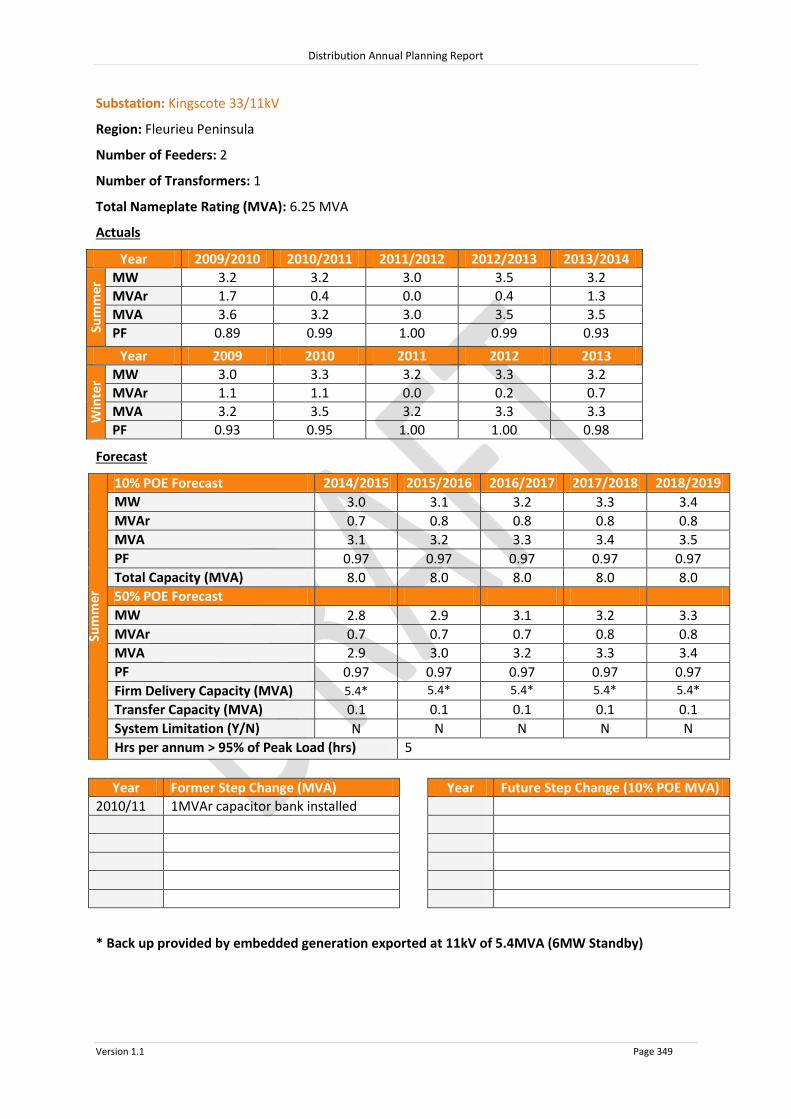
Distribution Annual Planning Report
Version 1.1 Page 349
Substation: Kingscote 33/11kV
Region: Fleurieu Peninsula
Number of Feeders: 2
Number of Transformers: 1
Total Nameplate Rating (MVA): 6.25 MVA
Actuals
Year 2009/2010 2010/2011 2011/2012 2012/2013 2013/2014
Sum
mer
MW 3.2 3.2 3.0 3.5 3.2
MVAr 1.7 0.4 0.0 0.4 1.3
MVA 3.6 3.2 3.0 3.5 3.5
PF 0.89 0.99 1.00 0.99 0.93
Year 2009 2010 2011 2012 2013
Win
ter MW 3.0 3.3 3.2 3.3 3.2
MVAr 1.1 1.1 0.0 0.2 0.7
MVA 3.2 3.5 3.2 3.3 3.3
PF 0.93 0.95 1.00 1.00 0.98
Forecast
Sum
mer
10% POE Forecast 2014/2015 2015/2016 2016/2017 2017/2018 2018/2019
MW 3.0 3.1 3.2 3.3 3.4
MVAr 0.7 0.8 0.8 0.8 0.8
MVA 3.1 3.2 3.3 3.4 3.5
PF 0.97 0.97 0.97 0.97 0.97
Total Capacity (MVA) 8.0 8.0 8.0 8.0 8.0
50% POE Forecast
MW 2.8 2.9 3.1 3.2 3.3
MVAr 0.7 0.7 0.7 0.8 0.8
MVA 2.9
3.0
3.2
3.3
3.4 PF 0.97 0.97 0.97 0.97 0.97
Firm Delivery Capacity (MVA) 5.4* 5.4* 5.4* 5.4* 5.4*
Transfer Capacity (MVA) 0.1
0.1
0.1
0.1
0.1 System Limitation (Y/N) N N N N N
Hrs per annum > 95% of Peak Load (hrs) 5
Year Former Step Change (MVA) Year Future Step Change (10% POE MVA)
2010/11 1MVAr capacitor bank installed
* Back up provided by embedded generation exported at 11kV of 5.4MVA (6MW Standby)

Distribution Annual Planning Report
Version 1.1 Page 350
Substation: MacGillivray 33/11kV
Region: Fleurieu Peninsula
Number of Feeders: 2
Number of Transformers: 2
Total Nameplate Rating (MVA): 2 MVA
Actuals
Year 2009/2010 2010/2011 2011/2012 2012/2013 2013/2014
Sum
mer
MW 1.9 1.7 1.5 1.7 2.1
MVAr 0.5 0.4 0.9 0.4 0.9
MVA 1.9 1.7 1.8 1.7 2.3
PF 0.96 0.98 0.86 0.98 0.92
Year 2009 2010 2011 2012 2013
Win
ter MW 1.7 1.8 1.6 1.6 1.8
MVAr 0.3 0.3 0.2 0.4 0.5
MVA 1.7 1.8 1.6 1.6 1.8
PF 0.99 0.99 1.00 0.97 0.96
Forecast
Sum
mer
10% POE Forecast 2014/2015 2015/2016 2016/2017 2017/2018 2018/2019
MW 1.9 1.9 1.9 1.9 1.9
MVAr 0.9 0.9 0.9 0.9 0.9
MVA 2.0 2.1 2.1 2.1 2.1
PF 0.91 0.91 0.91 0.91 0.91
Total Capacity (MVA) 2.6 2.6 2.6 2.6 2.6
50% POE Forecast
MW 1.7 1.7 1.8 1.8 1.8
MVAr 0.8 0.8 0.8 0.8 0.8
MVA 1.9
1.9
1.9
2.0
2.0 PF 0.91 0.91 0.91 0.91 0.91
Firm Delivery Capacity (MVA) 1.5 1.5 1.5 1.5 1.5
Transfer Capacity (MVA) 0.0
0.0
0.0
0.0
0.0 System Limitation (Y/N) Y* Y* Y* Y* Y*
Hrs per annum > 95% of Peak Load (hrs) 0.5
Year Former Step Change (MVA) Year Future Step Change (10% POE MVA)
*Within planning criteria risk margin

Distribution Annual Planning Report
Version 1.1 Page 351
Substation: Myponga 66/11kV
Region: Fleurieu Peninsula
Number of Feeders: 4
Number of Transformers: 2
Total Nameplate Rating (MVA): 10 MVA
Actuals
Year 2009/2010 2010/2011 2011/2012 2012/2013 2013/2014
Sum
mer
MW N/A N/A 7.1 5.2 5.2
MVAr N/A N/A 2.7 2.3 2.1
MVA N/A N/A 7.6 5.6 5.6
PF N/A N/A 0.93 0.91 0.93
Year 2009 2010 2011 2012 2013
Win
ter MW N/A N/A N/A 4.5 4.4
MVAr N/A N/A N/A 0.9 1.1
MVA N/A N/A N/A 4.6 4.5
PF N/A N/A N/A 0.98 0.97
Forecast
Sum
mer
10% POE Forecast 2014/2015 2015/2016 2016/2017 2017/2018 2018/2019
MW 5.1 5.1 5.1 5.0 5.0
MVAr 2.1 2.1 2.1 2.1 2.1
MVA 5.5 5.5 5.5 5.5 5.4
PF 0.92 0.92 0.92 0.92 0.92
Total Capacity (MVA) 14.2 14.2 14.2 14.2 14.2
50% POE Forecast
MW 4.6 4.5 4.5 4.5 4.5
MVAr 1.9 1.9 1.9 1.9 1.9
MVA 4.9
4.9
4.9
4.9
4.8 PF 0.92 0.92 0.92 0.92 0.92
Firm Delivery Capacity (MVA) 7.5 7.5 7.5 7.5 7.5
Transfer Capacity (MVA) 1.4
1.4
1.4
1.4
1.5 System Limitation (Y/N) N N N N N
Hrs per annum > 95% of Peak Load (hrs) 5
Year Former Step Change (MVA) Year Future Step Change (10% POE MVA)
2009/10 +0.3MVA from Aldinga

Distribution Annual Planning Report
Version 1.1 Page 352
Substation: Penneshaw 33/11kV
Region: Fleurieu Peninsula
Number of Feeders: 1
Number of Transformers: 1
Total Nameplate Rating (MVA): 1.5 MVA
Actuals
Year 2009/2010 2010/2011 2011/2012 2012/2013 2013/2014
Sum
mer
MW 0.7 0.6 0.7 0.6 0.7
MVAr 0.3 0.3 0.3 0.2 0.3
MVA 0.7 0.7 0.7 0.6 0.8
PF 0.93 0.93 0.93 0.93 0.93
Year 2009 2010 2011 2012 2013
Win
ter MW 0.6 0.7 0.7 0.6 0.7
MVAr 0.3 0.3 0.3 0.2 0.3
MVA 0.7 0.7 0.7 0.7 0.8
PF 0.93 0.93 0.93 0.93 0.92
Forecast
Sum
mer
10% POE Forecast 2014/2015 2015/2016 2016/2017 2017/2018 2018/2019
MW 0.7 0.7 0.7 0.7 0.8
MVAr 0.3 0.3 0.3 0.3 0.3
MVA 0.8 0.8 0.8 0.8 0.8
PF 0.91 0.91 0.91 0.91 0.91
Total Capacity (MVA) 2.0 2.0 2.0 2.0 2.0
50% POE Forecast
MW 0.7 0.7 0.7 0.7 0.8
MVAr 0.3 0.3 0.3 0.3 0.3
MVA 0.8
0.8
0.8
0.8
0.8 PF 0.91 0.91 0.91 0.91 0.91
Firm Delivery Capacity (MVA) 0.0 0.0 0.0 0.0 0.0
Transfer Capacity (MVA) 0.7
0.7
0.7
0.7
0.7 System Limitation (Y/N) Y* Y* Y* Y* Y*
Hrs per annum > 95% of Peak Load (hrs) 7
Year Former Step Change (MVA) Year Future Step Change (10% POE MVA)
*Within planning criteria risk margin

Distribution Annual Planning Report
Version 1.1 Page 353
Substation: Square Water Hole 66/11kV
Region: Fleurieu Peninsula
Number of Feeders: 4
Number of Transformers: 1
Total Nameplate Rating (MVA): 5 MVA
Actuals
Year 2009/2010 2010/2011 2011/2012 2012/2013 2013/2014
Sum
mer
MW 4.0 4.4 3.7 3.9 4.2
MVAr 1.7 1.7 1.3 1.5 1.4
MVA 4.4 4.7 3.9 4.2 4.4
PF 0.92 0.94 0.94 0.94 0.95
Year 2009 2010 2011 2012 2013
Win
ter MW 3.2 3.3 3.3 3.5 3.3
MVAr 0.0 0.3 0.3 0.0 0.2
MVA 3.2 3.3 3.4 3.5 3.3
PF 1.00 1.00 1.00 1.00 1.00
Forecast
Sum
mer
10% POE Forecast 2014/2015 2015/2016 2016/2017 2017/2018 2018/2019
MW 3.9 4.0 4.0 4.1 4.1
MVAr 1.4 1.4 1.4 1.4 1.4
MVA 4.2 4.2 4.3 4.3 4.3
PF 0.95 0.95 0.95 0.95 0.95
Total Capacity (MVA) 7.1 7.1 7.1 7.1 7.1
50% POE Forecast
MW 3.5 3.6 3.6 3.7 3.7
MVAr 1.2 1.2 1.3 1.3 1.3
MVA 3.7
3.8
3.8
3.9
3.9 PF 0.95 0.95 0.95 0.95 0.95
Firm Delivery Capacity (MVA) 0.0 0.0 0.0 0.0 0.0
Transfer Capacity (MVA) 1.2
1.2
1.2
1.2
1.2 System Limitation (Y/N) Y* Y* Y* Y* Y*
Hrs per annum > 95% of Peak Load (hrs) 5
Year Former Step Change (MVA) Year Future Step Change (10% POE MVA)
*Within planning criteria risk margin

Distribution Annual Planning Report
Version 1.1 Page 354
Substation: Victor Harbor 66/11kV
Region: Fleurieu Peninsula
Number of Feeders: 6
Number of Transformers: 2
Total Nameplate Rating (MVA): 50 MVA
Actuals
Year 2009/2010 2010/2011 2011/2012 2012/2013 2013/2014
Sum
mer
MW 26.4 20.9 22.2 23.8 25.3
MVAr 1.3 2.0 0.8 0.7 3.3
MVA 26.4 21.0 22.2 23.8 25.5
PF 1.00 1.00 1.00 1.00 0.99
Year 2009 2010 2011 2012 2013
Win
ter MW 20.9 22.2 22.3 22.5 21.4
MVAr 1.8 1.6 0.6 0.7 1.6
MVA 21.0 22.3 22.3 22.5 21.4
PF 1.00 1.00 1.00 1.00 1.00
Forecast*
Sum
mer
10% POE Forecast 2014/2015 2015/2016 2016/2017 2017/2018 2018/2019
MW 25.4 25.3 25.2 25.1 25.0
MVAr 2.0 2.0 2.0 2.0 2.0
MVA 25.5 25.4 25.3 25.2 25.1
PF 1.00 1.00 1.00 1.00 1.00
Total Capacity (MVA) 62.7 62.7 62.7 62.7 62.7
50% POE Forecast
MW 22.8 22.8 22.7 22.6 22.5
MVAr 1.8 1.8 1.8 1.8 1.8
MVA 22.9 22.8 22.7 22.7 22.6
PF 1.00 1.00 1.00 1.00 1.00
Firm Delivery Capacity (MVA) 36.9 36.9 36.9 36.9 36.9
Transfer Capacity (MVA) 0.6
0.6
0.6
0.6
0.6 System Limitation (Y/N) N N N N N
Hrs per annum > 95% of Peak Load (hrs) 5
Year Former Step Change (MVA) Year Future Step Change (10% POE MVA)
2009/10 9.0MVAr Capacitor Bank installed
2012/13 +0.6MVA Customer load increase
*NOTE: Forecast includes a post model adjustment to take into account holiday peak loads

Distribution Annual Planning Report
Version 1.1 Page 355
Substation: Yankalilla 66/33kV
Region: Fleurieu Peninsula
Number of Transformers: 1
Total Nameplate Rating (MVA): 12.5 MVA
Actuals
Year 2009/2010 2010/2011 2011/2012 2012/2013 2013/2014
Sum
mer
MW 1.3 1.2 1.4 1.2 1.1
MVAr 0.6 0.4 0.4 0.3 0.1
MVA 1.4 1.3 1.5 1.2 1.1
PF 0.90 0.95 0.97 0.97 1.00
Year 2009 2010 2011 2012 2013
Win
ter MW 1.1 1.3 1.4 1.3 1.0
MVAr 0.3 0.4 0.3 0.1 0.0
MVA 1.1 1.4 1.4 1.3 1.0
PF 0.96 0.97 0.98 1.00 1.00
Forecast
Sum
mer
10% POE Forecast 2014/2015 2015/2016 2016/2017 2017/2018 2018/2019
MW 1.5 1.5 1.5 1.5 1.5
MVAr 0.2 0.2 0.2 0.2 0.2
MVA 1.5 1.5 1.5 1.5 1.5
PF 0.99 0.99 0.99 0.99 0.99
Total Capacity (MVA) 17.7 17.7 17.7 17.7 17.7
50% POE Forecast
MW 1.3 1.3 1.3 1.3 1.3
MVAr 0.2 0.2 0.2 0.2 0.2
MVA 1.4
1.4
1.4
1.4
1.4 PF 0.99 0.99 0.99 0.99 0.99
Firm Delivery Capacity (MVA) 0.0 0.0 0.0 0.0 0.0
Transfer Capacity (MVA) 8.6
8.6
8.6
8.6
8.6 System Limitation (Y/N) N N N N N
Hrs per annum > 95% of Peak Load (hrs) 5
Year Former Step Change (MVA) Year Future Step Change (10% POE MVA)

Distribution Annual Planning Report
Version 1.1 Page 356
Substation: Yankalilla 66/11kV
Region: Fleurieu Peninsula
Number of Feeders: 3
Number of Transformers: 1
Total Nameplate Rating (MVA): 12.5 MVA
Actuals
Year 2009/2010 2010/2011 2011/2012 2012/2013 2013/2014
Sum
mer
MW 6.5 5.1 8.0 6.3 6.3
MVAr 2.9 2.3 2.0 3.4 2.9
MVA 7.1 5.6 8.2 7.1 7.0
PF 0.91 0.91 0.97 0.88 0.91
Year 2009 2010 2011 2012 2013
Win
ter MW 5.0 6.0 5.0 6.0 5.0
MVAr 0.9 0.0 1.0 1.0 1.0
MVA 5.1 6.0 5.1 6.1 5.1
PF 0.98 1.00 0.98 0.99 0.98
Forecast
Sum
mer
10% POE Forecast 2014/2015 2015/2016 2016/2017 2017/2018 2018/2019
MW 6.1 6.1 6.1 6.1 6.1
MVAr 2.9 2.9 2.9 2.9 2.9
MVA 6.7 6.7 6.7 6.7 6.7
PF 0.90 0.90 0.90 0.90 0.90
Total Capacity (MVA) 16.6 16.6 16.6 16.6 16.6
50% POE Forecast
MW 5.2 5.2 5.2 5.2 5.2
MVAr 2.5 2.5 2.5 2.5 2.5
MVA 5.8
5.8
5.8
5.8
5.8 PF 0.90 0.90 0.90 0.90 0.90
Firm Delivery Capacity (MVA) 0.0 0.0 0.0 0.0 0.0
Transfer Capacity (MVA) 7.5
7.6
7.7
7.8
7.9 System Limitation (Y/N) N N N N N
Hrs per annum > 95% of Peak Load (hrs) 5
Year Former Step Change (MVA) Year Future Step Change (10% POE MVA)

Distribution Annual Planning Report
Version 1.1 Page 357
8.15.3 Fleurieu Peninsula Non SCADA Substations 10% POE Forecast
2014/2015 2015/2016 2016/2017 2017/2018 2018/2019
Substation No of
TFs
TF Nameplate
Rating (MVA)
Total Capacity (MVA)
10% POE Forecast (MVA)
10% POE Forecast (MVA)
10% POE Forecast (MVA)
10% POE Forecast (MVA)
10% POE Forecast (MVA)
American River Reg 1 10.0 12.5 5.2 5.3 5.4 5.5 5.6
Hay Flat 1 0.2 0.3 0.1 0.1 0.1 0.1 0.1
Salt Cliffs 1 0.5 0.7 0.2 0.2 0.2 0.2 0.2
Second Valley 1 0.5 0.7 0.3 0.3 0.3 0.3 0.3
Wirrina Cove 1 1.5 2.0 0.7 0.7 0.7 0.7 0.7
Yankalilla Hill 1 0.3 0.4 0.02 0.02 0.02 0.02 0.02
System Limitations: Nil

Distribution Annual Planning Report
Version 1.1 Page 358
8.15.4 Fleurieu Peninsula 66kV Sub-transmission Lines
Line Name - From
To Total
Capacity^ (MVA)
Forecast 2014/2015
MVA
Forecast 2015/2016
MVA
Forecast 2016/2017
MVA
Forecast 2017/2018
MVA
Forecast 2018/2019
MVA
66KV LINES ON FLEURIEU PENINSULA
WILLUNGA MYPONGA 71.8 22.1 22.2 22.3 22.3 22.4
MYPONGA YANKALILLA 71.8 16.6 16.7 16.8 16.9 17.0
YANKALILLA CAPE JERVIS 61.0 7.0 7.0 7.1 7.2 7.3
WILLUNGA SQWATER HOLE 71.8 44.5 44.4 44.3 44.2 44.0
SQWATER HOLE VICTOR HARBOR 40.6 25.5 25.4 25.3 25.2 25.1
SQWATER HOLE GOOLWA 53.2 14.9 14.8 14.7 14.6 14.6
^ The published rating is based on a thermal limit or a limit required to maintain adequate clearances and does not take into account voltage limitations on the network which may further reduce the published rating. System Limitations: Nil
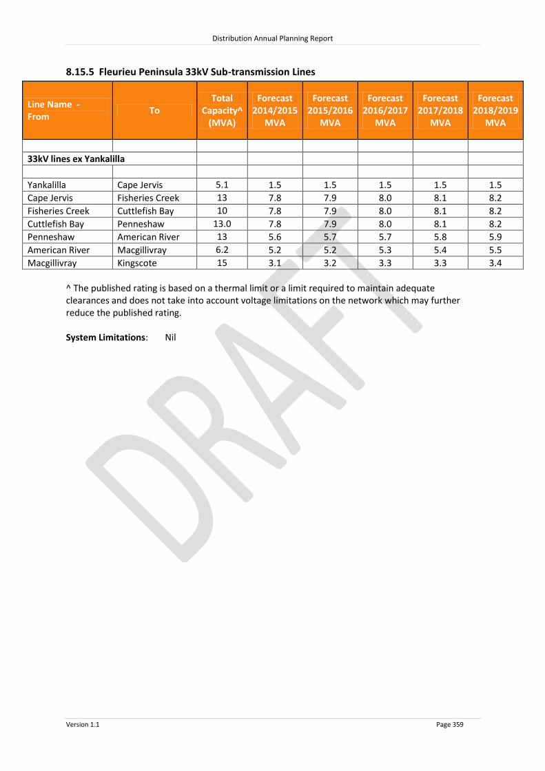
Distribution Annual Planning Report
Version 1.1 Page 359
8.15.5 Fleurieu Peninsula 33kV Sub-transmission Lines
Line Name - From
To Total
Capacity^ (MVA)
Forecast 2014/2015
MVA
Forecast 2015/2016
MVA
Forecast 2016/2017
MVA
Forecast 2017/2018
MVA
Forecast 2018/2019
MVA
33kV lines ex Yankalilla
Yankalilla Cape Jervis 5.1 1.5 1.5 1.5 1.5 1.5
Cape Jervis Fisheries Creek 13 7.8 7.9 8.0 8.1 8.2
Fisheries Creek Cuttlefish Bay 10 7.8 7.9 8.0 8.1 8.2
Cuttlefish Bay Penneshaw 13.0 7.8 7.9 8.0 8.1 8.2
Penneshaw American River 13 5.6 5.7 5.7 5.8 5.9
American River Macgillivray 6.2 5.2 5.2 5.3 5.4 5.5
Macgillivray Kingscote 15 3.1 3.2 3.3 3.3 3.4
^ The published rating is based on a thermal limit or a limit required to maintain adequate clearances and does not take into account voltage limitations on the network which may further reduce the published rating. System Limitations: Nil

Distribution Annual Planning Report
Version 1.1 Page 360
8.16 Riverland Regional Development Plan
The Riverland The SA Power Networks’ Riverland region includes the region from Berri extending north-west to Morgan, south-west to Swan Reach, and north-east to Renmark and Paringa. There are two main connection points in the Riverland, being Berri/Monash and North West Bend. SA Power Networks’ Distribution Network Electricity is supplied to the various towns and localities throughout the Riverland region via Zone Substations. These Zone Substations are operated at either 66,000 Volts stepped down to 11,000 or 33,000 Volts, or 33,000 Volts stepped down to 11,000 Volts. Customers are supplied from SA Power Networks distribution system via 33kV, 11kV and 19kV primary distribution feeders, which are connected to distribution substations. These feeders are extended and upgraded as required to meet customer demand and customer connection requests. Large customer projects may require a Zone Substation upgrade as well as feeder modifications, therefore SA Power Networks should be notified as early as possible during the planning stages of a project so that customer connection requirements can be met. There are no system limitations forecast for the primary distribution feeders under normal conditions in the Riverland Region in the next two years.
8.16.1 Riverland SCADA Substations
Source Connection Point Associated SCADA Substations
Berri / Monash Berri 11kV
Glossop
Loveday
Loxton
Paringa 11kV
Paringa 33kV
Pyap
Remark
Woolpunda
North West Bend Ramco
Swan Reach 11kV
Waikerie

PORTEE
SWAN REACH 33/11KV
NORTH WEST BEND
SWAN REACH 66/33KV
ROONKA
PARINGA
CORDOLAQUALCO
MORGAN CADELL
RAMCO
WAIKERIE
LOVEDAY
PYAP
GLOSSOPBERRI
LOXTON
LYRUP
WOOLPUNDA
MONASH
RENMARK
Legend275kV Transmission Line132kV Transmission Line66kV Sub Transmission Line33kV Sub Transmission LineSubstation
0 5 10 15 20 25
Kilometres
RIVERLANDMIDNORTH
MURRAY LANDS
System Limitation.

Distribution Annual Planning Report
Version 1.1 Page 362
Substation: Berri / Monash 132/66kV
Region: Riverland
(ETC) Transmission Category: 4
Number of Transformers: 3
Total Nameplate Rating (MVA): 160 MVA
Actuals
Year 2009/2010 2010/2011 2011/2012 2012/2013 2013/2014
Sum
mer
MW 94.0 84.5 79.1 85.0 92.9
MVAr 19.1 26.5 21.8 24.8 23.0
MVA 95.9 88.5 82.0 88.5 95.7
PF 0.98 0.98 0.96 0.96 0.97
Year 2009 2010 2011 2012 2013
Win
ter MW 49.5 46.7 36.5 30.1 34.5
MVAr 5.0 0.4 0.3 12.2 1.7
MVA 49.7 46.7 36.5 32.5 34.5
PF 0.99 1.00 1.00 0.93 1.00
Forecast
Sum
mer
10% POE Forecast 2014/2015 2015/2016 2016/2017 2017/2018 2018/2019
MW 94.9 93.9 92.9 91.9 91.0
MVAr 27.3 27.0 26.7 26.4 26.2
MVA 98.8 97.7 96.7 95.7 94.7
PF 0.96 0.96 0.96 0.96 0.96
Firm Delivery Capacity (MVA) 140.0 140.0 140.0 140.0 140.0
System Limitation (Y/N) N N N N N
Hrs per annum > 95% of Peak Load (hrs) 13
Year Former Step Change (MVA) Year Future Step Change (10% POE MVA)
2009/10 -2.0MW Customer shutdown
2012/13 +2.0MW Customer load increase

Distribution Annual Planning Report
Version 1.1 Page 363
Substation: North West Bend 132/66kV
Region: Riverland
(ETC) Transmission Category: 4
Number of Transformers: 3
Total Nameplate Rating (MVA): 65 MVA
Actuals
Year 2009/2010 2010/2011 2011/2012 2012/2013 2013/2014
Sum
mer
MW 28.8 24.1 25.5 25.7 26.9
MVAr 5.8 7.8 7.7 7.6 8.7
MVA 29.4 25.3 26.6 26.8 28.3
PF 0.98 0.95 0.96 0.96 0.95
Year 2009 2010 2011 2012 2013
Win
ter MW 14.0 15.8 13.8 13.0 10.2
MVAr 0.9 0.6 4.6 3.4 3.8
MVA 14.1 15.8 14.5 13.5 10.9
PF 1.00 1.00 0.95 0.97 0.94
Forecast
Sum
mer
10% POE Forecast 2014/2015 2015/2016 2016/2017 2017/2018 2018/2019
MW 27.2 26.9 26.6 26.3 25.9
MVAr 8.3 8.2 8.1 8.0 7.9
MVA 28.5 28.1 27.8 27.5 27.1
PF 0.96 0.96 0.96 0.96 0.96
Firm Delivery Capacity (MVA) 55.6 55.6 55.6 55.6 55.6
System Limitation (Y/N) N N N N N
Hrs per annum > 95% of Peak Load (hrs) 4
Year Former Step Change (MVA) Year Future Step Change (10% POE MVA)

Distribution Annual Planning Report
Version 1.1 Page 364
Substation: Berri 66/11kV
Region: Riverland
Number of Feeders: 4
Number of Transformers: 2
Total Nameplate Rating (MVA): 20 MVA
Actuals
Year 2009/2010 2010/2011 2011/2012 2012/2013 2013/2014
Sum
mer
MW 12.6 12.4 10.4 11.8 11.5
MVAr 1.3 1.1 0.6 0.0 0.3
MVA 12.7 12.4 10.4 11.8 11.5
PF 0.99 0.99 0.99 1.00 1.00
Year 2009 2010 2011 2012 2013
Win
ter MW 8.6 9.0 7.5 7.4 7.2
MVAr 3.8 3.4 2.8 2.6 2.2
MVA 9.4 9.7 8.0 7.8 7.5
PF 0.91 0.94 0.94 0.94 0.96
Forecast
Sum
mer
10% POE Forecast 2014/2015 2015/2016 2016/2017 2017/2018 2018/2019
MW 11.5 11.2 10.8 10.5 10.1
MVAr 2.6 2.5 2.4 2.4 2.3
MVA 11.8 11.4 11.1 10.7 10.4
PF 0.98 0.98 0.98 0.98 0.98
Total Capacity (MVA) 28.0 28.0 28.0 28.0 28.0
50% POE Forecast
MW 10.6 10.2 9.8 9.5 9.2
MVAr 2.4 2.3 2.2 2.2 2.1
MVA 10.8
10.5
10.1
9.8
9.4 PF 0.98 0.98 0.98 0.98 0.98
Firm Delivery Capacity (MVA) 15.0 15.0 15.0 15.0 15.0
Transfer Capacity (MVA) 2.5
2.6
2.7
2.8
2.9 System Limitation (Y/N) N N N N N
Hrs per annum > 95% of Peak Load (hrs) 9
Year Former Step Change (MVA) Year Future Step Change (10% POE MVA)

Distribution Annual Planning Report
Version 1.1 Page 365
Substation: Glossop 66/11kV
Region: Riverland
Number of Feeders: 4
Number of Transformers: 2
Total Nameplate Rating (MVA): 12.5 MVA
Actuals
Year 2009/2010 2010/2011 2011/2012 2012/2013 2013/2014
Sum
mer
MW 9.9 7.3 8.3 9.0 9.2
MVAr 3.8 3.0 3.6 4.4 4.4
MVA 10.6 7.9 9.0 10.0 10.2
PF 0.93 0.92 0.92 0.90 0.90
Year 2009 2010 2011 2012 2013
Win
ter MW 6.0 4.7 4.5 5.0 4.5
MVAr 0.7 0.3 0.9 1.8 2.1
MVA 6.0 4.7 4.6 5.3 5.0
PF 0.99 1.00 0.98 0.94 0.90
Forecast
Sum
mer
10% POE Forecast 2014/2015 2015/2016 2016/2017 2017/2018 2018/2019
MW 9.1 9.0 8.9 8.8 8.8
MVAr 4.2 4.2 4.2 4.1 4.1
MVA 10.0 9.9 9.9 9.7 9.6
PF 0.91 0.91 0.91 0.91 0.91
Total Capacity (MVA) 15.4 15.4 15.4 15.4 15.4
50% POE Forecast
MW 9.1 9.1 9.0 8.9 8.8
MVAr 4.2 4.2 4.2 4.1 4.1
MVA 10.1 10.0 9.9 9.8 9.7
PF 0.91 0.91 0.91 0.91 0.91
Firm Delivery Capacity (MVA) 7.5 7.5 7.5 7.5 7.5
Transfer Capacity (MVA) 3.0
3.1
3.1
3.1
3.2 System Limitation (Y/N) N N N N N
Hrs per annum > 95% of Peak Load (hrs) 6
Year Former Step Change (MVA) Year Future Step Change (10% POE MVA)
2011/12 +1.5MVA from Loveday

Distribution Annual Planning Report
Version 1.1 Page 366
Substation: Loveday 66/11kV
Region: Riverland
Number of Feeders: 5
Number of Transformers: 3
Total Nameplate Rating (MVA): 15 MVA
Actuals
Year 2009/2010 2010/2011 2011/2012 2012/2013 2013/2014
Sum
mer
MW 13.5 11.6 11.3 11.8 12.3
MVAr 0.0 0.0 2.9 3.1 0.5
MVA 13.5 11.6 11.7 12.2 12.3
PF 1.00 1.00 0.97 0.97 1.00
Year 2009 2010 2011 2012 2013
Win
ter MW 6.4 7.3 7.1 6.8 6.2
MVAr 3.1 0.1 1.9 2.7 0.6
MVA 7.1 7.3 7.4 7.3 6.2
PF 0.90 1.00 0.97 0.93 1.00
Forecast
Sum
mer
10% POE Forecast 2014/2015 2015/2016 2016/2017 2017/2018 2018/2019
MW 12.0 11.8 11.6 11.4 11.2
MVAr 2.6 2.5 2.5 2.4 2.4
MVA 12.3 12.1 11.9 11.7 11.4
PF 0.98 0.98 0.98 0.98 0.98
Total Capacity (MVA) 20.4 20.4 20.4 20.4 20.4
50% POE Forecast
MW 10.8 10.6 10.5 10.3 10.1
MVAr 2.3 2.3 2.2 2.2 2.1
MVA 11.1 10.9 10.7 10.5 10.3
PF 0.98 0.98 0.98 0.98 0.98
Firm Delivery Capacity (MVA) 14.6 14.6 14.6 14.6 14.6
Transfer Capacity (MVA) 0.4
0.4
0.4
0.4
0.4 System Limitation (Y/N) N N N N N
Hrs per annum > 95% of Peak Load (hrs) 6
Year Former Step Change (MVA) Year Future Step Change (10% POE MVA)
2011/12 -1.5MVA to Glossop
+0.5MVA Customer load increase

Distribution Annual Planning Report
Version 1.1 Page 367
Substation: Loxton 66/11kV
Region: Riverland
Number of Feeders: 4
Number of Transformers: 3
Total Nameplate Rating (MVA): 18.75 MVA
Actuals
Year 2009/2010 2010/2011 2011/2012 2012/2013 2013/2014
Sum
mer
MW 11.8 11.2 11.4 9.0 12.6
MVAr 0.0 0.0 1.0 4.3 1.9
MVA 11.8 11.2 11.4 10.0 12.7
PF 1.00 1.00 1.00 0.90 0.99
Year 2009 2010 2011 2012 2013
Win
ter MW 6.6 5.7 6.8 6.2 6.1
MVAr 2.3 1.4 1.6 1.6 0.7
MVA 7.0 5.9 7.0 6.4 6.2
PF 0.94 0.97 0.97 0.97 0.99
Forecast
Sum
mer
10% POE Forecast 2014/2015 2015/2016 2016/2017 2017/2018 2018/2019
MW 13.0 12.8 12.6 12.4 12.3
MVAr 1.5 1.5 1.4 1.4 1.4
MVA 13.1 12.9 12.7 12.5 12.4
PF 0.99 0.99 0.99 0.99 0.99
Total Capacity (MVA) 19.9 19.9 19.9 19.9 19.9
50% POE Forecast
MW 11.9 11.7 11.6 11.5 11.3
MVAr 1.4 1.3 1.3 1.3 1.3
MVA 12.0 11.8 11.7 11.5 11.4
PF 0.99 0.99 0.99 0.99 0.99
Firm Delivery Capacity (MVA) 14.6 14.6 14.6 14.6 14.6
Transfer Capacity (MVA) 0.8
0.8
0.9
0.9
0.9 System Limitation (Y/N) N N N N N
Hrs per annum > 95% of Peak Load (hrs) 8
Year Former Step Change (MVA) Year Future Step Change (10% POE MVA)
2009/10 -0.5MVA to Lyrup

Distribution Annual Planning Report
Version 1.1 Page 368
Substation: Paringa 66/33kV
Region: Riverland
Number of Transformers: 1
Total Nameplate Rating (MVA): 32 MVA
Actuals
Year 2009/2010 2010/2011 2011/2012 2012/2013 2013/2014
Sum
mer
MW 8.7 8.2 8.6 10.0 9.8
MVAr 3.8 3.5 3.4 4.1 3.8
MVA 9.5 8.9 9.3 10.8 10.6
PF 0.92 0.92 0.93 0.93 0.93
Year 2009 2010 2011 2012 2013
Win
ter MW 3.7 3.5 4.1 4.6 5.8
MVAr 1.2 1.1 1.8 1.4 2.3
MVA 3.9 3.7 4.4 4.8 6.2
PF 0.95 0.95 0.92 0.96 0.93
Forecast
Sum
mer
10% POE Forecast 2014/2015 2015/2016 2016/2017 2017/2018 2018/2019
MW 11.6 14.2 14.4 14.5 14.6
MVAr 4.7 5.6 5.7 5.8 5.8
MVA 12.5 15.2 15.4 15.6 15.8
PF 0.93 0.93 0.93 0.93 0.93
Total Capacity (MVA) 34.0 34.0 34.0 34.0 34.0
50% POE Forecast
MW 10.6 12.8 13 13.1 13.2
MVAr 4.2 5.1 5.2 5.2 5.3
MVA 11.4 13.8 14 14 14.2
PF 0.93 0.93 0.93 0.93 0.93
Firm Delivery Capacity (MVA) 0.0 0.0 0.0 0.0 0.0
Transfer Capacity (MVA) 14.8 14.8 14.8 14.8 14.8
System Limitation (Y/N) Y Y Y Y Y
Hrs per annum > 95% of Peak Load (hrs) 9
Year Former Step Change (MVA) Year Future Step Change (10% POE MVA)
2009/10 +1.2MVA Customer load increase

Distribution Annual Planning Report
Version 1.1 Page 369
Substation: Paringa 33/11kV
Region: Riverland
Number of Feeders:2
Number of Transformers: 1
Total Nameplate Rating (MVA): 2.5 MVA
Actuals
Year 2009/2010 2010/2011 2011/2012 2012/2013 2013/2014
Sum
mer
MW 2.3 2.4 2.1 2.2 2.4
MVAr 1.0 1.0 0.8 0.7 0.9
MVA 2.5 2.6 2.3 2.3 2.6
PF 0.92 0.93 0.94 0.96 0.94
Year 2009 2010 2011 2012 2013
Win
ter MW 1.3 1.4 1.5 1.5 1.4
MVAr 0.3 0.3 0.5 0.0 0.5
MVA 1.3 1.4 1.5 1.5 1.5
PF 0.97 0.97 0.95 1.00 0.94
Forecast
Sum
mer
10% POE Forecast 2014/2015 2015/2016 2016/2017 2017/2018 2018/2019
MW 2.4 2.4 2.4 2.3 2.3
MVAr 0.9 0.9 0.9 0.9 0.9
MVA 2.5 2.5 2.5 2.5 2.5
PF 0.94 0.94 0.94 0.94 0.94
Total Capacity (MVA) 3.3 3.3 3.3 3.3 3.3
50% POE Forecast
MW 2.1
2.1
2.1
2.1
2.1 MVAr 0.8
0.8
0.8
0.8
0.8
MVA 2.3
2.3
2.3
2.2
2.2 PF 0.94
0.94
0.94
0.94
0.94
Firm Delivery Capacity (MVA) 0.0 0.0 0.0 0.0 0.0
Transfer Capacity (MVA) 3.7
3.7
3.7
3.8
3.8 System Limitation (Y/N) N N N N N
Hrs per annum > 95% of Peak Load (hrs) 5
Year Former Step Change (MVA) Year Future Step Change (10% POE MVA)

Distribution Annual Planning Report
Version 1.1 Page 370
Substation: Pyap 66/11kV
Region: Riverland
Number of Feeders: 3
Number of Transformers: 2
Total Nameplate Rating (MVA): 12.5 MVA
Actuals
Year 2009/2010 2010/2011 2011/2012 2012/2013 2013/2014
Sum
mer
MW 8.2 7.8 7.1 7.5 8.1
MVAr 0.0 0.0 0.5 0.5 1.0
MVA 8.2 7.8 7.1 7.5 8.2
PF 1.00 1.00 1.00 1.00 0.99
Year 2009 2010 2011 2012 2013
Win
ter MW 4.6 5.4 6.1 4.7 4.8
MVAr 2.6 1.0 0.9 1.3 0.9
MVA 5.3 5.5 6.2 4.9 4.9
PF 0.87 0.99 0.99 0.96 0.99
Forecast
Sum
mer
10% POE Forecast 2014/2015 2015/2016 2016/2017 2017/2018 2018/2019
MW 8.3 8.1 8.0 7.8 7.7
MVAr 0.8 0.8 0.8 0.8 0.7
MVA 8.3 8.2 8.0 7.9 7.7
PF 1.00 1.00 1.00 1.00 1.00
Total Capacity (MVA) 15.2 15.2 15.2 15.2 15.2
50% POE Forecast
MW 7.4 7.2 7.1 6.9 6.8
MVAr 0.7 0.7 0.7 0.7 0.7
MVA 7.4
7.3
7.1
7.0
6.8 PF 1.00 1.00 1.00 1.00 1.00
Firm Delivery Capacity (MVA) 7.5 7.5 7.5 7.5 7.5
Transfer Capacity (MVA) 1.9
1.9
1.9
2.0
2.0 System Limitation (Y/N) N N N N N
Hrs per annum > 95% of Peak Load (hrs) 5
Year Former Step Change (MVA) Year Future Step Change (10% POE MVA)

Distribution Annual Planning Report
Version 1.1 Page 371
Substation: Ramco 66/11kV
Region: Riverland
Number of Feeders: 3
Number of Transformers: 2
Total Nameplate Rating (MVA): 7 MVA
Actuals
Year 2009/2010 2010/2011 2011/2012 2012/2013 2013/2014
Sum
mer
MW N/A N/A N/A 5.3 5.9
MVAr N/A N/A N/A 0.8 2.5
MVA N/A N/A N/A 5.3 6.4
PF N/A N/A N/A 0.99 0.92
Year 2009 2010 2011 2012 2013
Win
ter MW N/A N/A N/A N/A 3.0
MVAr N/A N/A N/A N/A 1.5
MVA N/A N/A N/A N/A 3.3
PF N/A N/A N/A N/A 0.89
Forecast
Sum
mer
10% POE Forecast 2014/2015 2015/2016 2016/2017 2017/2018 2018/2019
MW 6.0 6.0 5.9 5.8 5.7
MVAr 2.6 2.6 2.6 2.5 2.5
MVA 6.6 6.5 6.4 6.3 6.3
PF 0.92 0.92 0.92 0.92 0.92
Total Capacity (MVA) 8.4 8.4 8.4 8.4 8.4
50% POE Forecast
MW 5.5 5.5 5.5 5.5 5.4
MVAr 2.4 2.4 2.4 2.4 2.4
MVA 6.1
6.0
6.0
6.0
5.9 PF 0.92 0.92 0.92 0.92 0.92
Firm Delivery Capacity (MVA) 4.8 4.8 4.8 4.8 4.8
Transfer Capacity (MVA) 1.6
1.7
1.7
1.7
1.7 System Limitation (Y/N) N N N N N
Hrs per annum > 95% of Peak Load (hrs) 5
Year Former Step Change (MVA) Year Future Step Change (10% POE MVA)

Distribution Annual Planning Report
Version 1.1 Page 372
Substation: Renmark 66/11kV
Region: Riverland
Number of Feeders: 6
Number of Transformers: 3
Total Nameplate Rating (MVA): 22.5 MVA
Actuals
Year 2009/2010 2010/2011 2011/2012 2012/2013 2013/2014
Sum
mer
MW 20.7 18.6 16.0 17.2 19.3
MVAr 0.0 3.9 2.0 3.3 0.9
MVA 20.7 19.0 16.1 17.5 19.3
PF 1.00 0.98 0.99 0.98 1.00
Year 2009 2010 2011 2012 2013
Win
ter MW 11.1 12.1 11.0 11.8 11.4
MVAr 4.3 1.6 1.0 0.3 1.3
MVA 11.9 12.2 11.0 11.8 11.5
PF 0.93 0.99 1.00 1.00 0.99
Forecast
Sum
mer
10% POE Forecast 2014/2015 2015/2016 2016/2017 2017/2018 2018/2019
MW 19.4 19.3 19.2 19.1 19.0
MVAr 3.4 3.3 3.3 3.3 3.3
MVA 19.7 19.6 19.5 19.4 19.2
PF 0.99 0.99 0.99 0.99 0.99
Total Capacity (MVA) 28.5 28.5 28.5 28.5 28.5
50% POE Forecast
MW 17.9 17.7 17.6 17.5 17.4
MVAr 3.1 3.1 3.0 3.0 3.0
MVA 18.1 18.0 17.9 17.7 17.6
PF 0.99 0.99 0.99 0.99 0.99
Firm Delivery Capacity (MVA) 21.2 21.2 21.2 21.2 21.2
Transfer Capacity (MVA) 0.0
0.0
0.0
0.0
0.0 System Limitation (Y/N) N N N N N
Hrs per annum > 95% of Peak Load (hrs) 6
Year Former Step Change (MVA) Year Future Step Change (10% POE MVA)

Distribution Annual Planning Report
Version 1.1 Page 373
Substation: Swan Reach 33/11kV
Region: Riverland
Number of Feeders: 1
Number of Transformers: 1
Total Nameplate Rating (MVA): 3 MVA
Actuals
Year 2009/2010 2010/2011 2011/2012 2012/2013 2013/2014
Sum
mer
MW N/A N/A N/A 1.3 1.2
MVAr N/A N/A N/A 0.5 0.5
MVA N/A N/A N/A 1.4 1.3
PF N/A N/A N/A 0.93 0.92
Year 2009 2010 2011 2012 2013
Win
ter MW N/A N/A N/A 0.9 0.8
MVAr N/A N/A N/A 0.4 0.6
MVA N/A N/A N/A 1.0 0.9
PF N/A N/A N/A 0.90 0.81
Forecast
Sum
mer
10% POE Forecast 2014/2015 2015/2016 2016/2017 2017/2018 2018/2019
MW 1.2 1.2 1.2 1.2 1.2
MVAr 0.5 0.5 0.5 0.5 0.5
MVA 1.3 1.3 1.3 1.3 1.3
PF 0.93 0.93 0.93 0.93 0.93
Total Capacity (MVA) 3.9 3.9 3.9 3.9 3.9
50% POE Forecast
MW 1.1 1.1 1.1 1.1 1.1
MVAr 0.4 0.4 0.4 0.4 0.4
MVA 1.2
1.2
1.2
1.2
1.2 PF 0.93 0.93 0.93 0.93 0.93
Firm Delivery Capacity (MVA) 0.0 0.0 0.0 0.0 0.0
Transfer Capacity (MVA) 0.0
0.0
0.0
0.0
0.0 System Limitation (Y/N) Y* Y* Y* Y* Y*
Hrs per annum > 95% of Peak Load (hrs) 4
Year Former Step Change (MVA) Year Future Step Change (10% POE MVA)
*Within planning criteria risk margin

Distribution Annual Planning Report
Version 1.1 Page 374
Substation: Waikerie 66/11kV
Region: Riverland
Number of Feeders: 3
Number of Transformers: 2
Total Nameplate Rating (MVA): 10 MVA
Actuals
Year 2009/2010 2010/2011 2011/2012 2012/2013 2013/2014
Sum
mer
MW 7.8 7.6 6.8 7.0 8.0
MVAr 0.0 2.5 0.0 0.0 0.4
MVA 7.8 8.0 6.8 7.0 8.0
PF 1.00 0.95 1.00 1.00 1.00
Year 2009 2010 2011 2012 2013
Win
ter MW 4.6 5.1 5.7 4.8 4.7
MVAr 1.6 1.6 1.0 1.4 1.6
MVA 4.8 5.3 5.7 5.0 5.0
PF 0.94 0.95 0.98 0.96 0.95
Forecast
Sum
mer
10% POE Forecast 2014/2015 2015/2016 2016/2017 2017/2018 2018/2019
MW 7.6 7.5 7.4 7.4 7.3
MVAr 0.3 0.3 0.3 0.3 0.3
MVA 7.6 7.5 7.5 7.4 7.3
PF 1.00 1.00 1.00 1.00 1.00
Total Capacity (MVA) 12.0 12.0 12.0 12.0 12.0
50% POE Forecast
MW 7.0 6.9 6.8 6.7 6.6
MVAr 0.3 0.3 0.3 0.3 0.3
MVA 7.0
6.9
6.8
6.7
6.6 PF 1.00 1.00 1.00 1.00 1.00
Firm Delivery Capacity (MVA) 6.7 6.7 6.7 6.7 6.7
Transfer Capacity (MVA) 1.6
1.6
1.6
1.6
1.6 System Limitation (Y/N) N N N N N
Hrs per annum > 95% of Peak Load (hrs) 6
Year Former Step Change (MVA) Year Future Step Change (10% POE MVA)

Distribution Annual Planning Report
Version 1.1 Page 375
Substation: Woolpunda 66/11kV
Region: Riverland
Number of Feeders: 2
Number of Transformers: 2
Total Nameplate Rating (MVA): 15 MVA
Actuals
Year 2009/2010 2010/2011 2011/2012 2012/2013 2013/2014
Sum
mer
MW 6.5 5.4 5.9 5.7 6.3
MVAr 1.6 1.4 1.6 1.5 1.6
MVA 6.7 5.6 6.1 5.9 6.5
PF 0.97 0.97 0.97 0.97 0.97
Year 2009 2010 2011 2012 2013
Win
ter MW 3.4 3.2 3.0 N/A N/A
MVAr 0.9 0.8 0.8 N/A N/A
MVA 3.5 3.3 3.1 N/A N/A
PF 0.97 0.97 0.97 N/A N/A
Forecast
Sum
mer
10% POE Forecast 2014/2015 2015/2016 2016/2017 2017/2018 2018/2019
MW 6.3 6.3 6.2 6.2 6.1
MVAr 1.6 1.6 1.6 1.5 1.5
MVA 6.5 6.5 6.4 6.4 6.3
PF 0.97 0.97 0.97 0.97 0.97
Total Capacity (MVA) 18.8 18.8 18.8 18.8 18.8
50% POE Forecast
MW 5.7 5.7 5.6 5.5 5.5
MVAr 1.4 1.4 1.4 1.4 1.4
MVA 5.9
5.8
5.8
5.7
5.7 PF 0.97 0.97 0.97 0.97 0.97
Firm Delivery Capacity (MVA) 10.6 10.6 10.6 10.6 10.6
Transfer Capacity (MVA) 0.0
0.0
0.0
0.0
0.0 System Limitation (Y/N) N N N N N
Hrs per annum > 95% of Peak Load (hrs) 9
Year Former Step Change (MVA) Year Future Step Change (10% POE MVA)
2012/13 +1.9MVA Customer load increase

Distribution Annual Planning Report
Version 1.1 Page 376
8.16.3 Riverland Non SCADA Substations 10% POE Forecast
2014/2015 2015/2016 2016/2017 2017/2018 2018/2019
Substation No of
TFs
TF Nameplate
Rating (MVA)
Total Capacity (MVA)
10% POE Forecast (MVA)
10% POE Forecast (MVA)
10% POE Forecast (MVA)
10% POE Forecast (MVA)
10% POE Forecast (MVA)
Cadell 2 2.0 2.6 2.5 2.4 2.4 2.4 2.3
Cordola 2 2.0 2.6 2.1 2.0 2.0 2.0 2.0
Lyrup 2 5.0 6.5 5.3 5.3 5.2 5.2 5.1
Morgan 1 1.0 1.3 1.1 1.1 1.1 1.0 1.0
Paringa 11kV 1 2.5 3.3 2.5 2.5 2.5 2.5 2.5
Portee 1 0.5 0.7 0.2 0.2 0.2 0.2 0.2
Qualco 1 2.5 3.3 2.9 2.8 2.8 2.8 2.7
Ramco 2 7.0 8.2 6.6 6.5 6.4 6.3 6.2
Roonka 1 6.25 8.0 2.8 2.7 2.7 2.7 2.7
System Limitations: Nil

Distribution Annual Planning Report
Version 1.1 Page 377
8.16.4 Riverland Non SCADA Substations 50% POE Forecast
2014/2015 2015/2016 2016/2017 2017/2018 2018/2019
Substation No of
TFs
TF Nameplate
Rating (MVA)
N-1 Emerg. Cyclic Rating (MVA)
50% POE
F’cast (MVA)
T’fer Cap
(MVA)
50% POE
F’cast (MVA)
T’fer Cap
(MVA)
50% POE
F’cast (MVA)
T’fer Cap
(MVA)
50% POE
F’cast (MVA)
T’fer Cap
(MVA)
50% POE
F’cast (MVA)
T’fer Cap
(MVA)
Lyrup 2 5.0 3.8 4.8 1.2 4.8 1.2 4.7 1.1 4.7 1.1 4.6 1.1
Ramco 2 7.0 4.8 6.1 1.6 6.0 1.6 6.0 1.6 6.0 1.6 5.9 1.6
System Limitations: Nil

Distribution Annual Planning Report
Version 1.1 Page 378
8.16.5 Riverland 66kV Sub-transmission Lines
Line Name - From
To Total
Capacity^ (MVA)
Forecast 2014/2015
MVA
Forecast 2015/2016
MVA
Forecast 2016/2017
MVA
Forecast 2017/2018
MVA
Forecast 2018/2019
MVA
66KV LINES IN THE RIVERLAND
NORTHWEST BEND MORGAN TEE 19.3 13.6 13.5 13.4 13.3 13.2
MORGAN TEE CORDOLA 19.6 12.5 12.4 12.4 12.3 12.2
CORDOLA ROONKA 19.3 10.4 10.4 10.3 10.3 10.2
ROONKA PORTEE 19.6 8.3 8.3 8.3 8.3 8.3
PORTEE SWAN REACH 10.3 8.1 8.1 8.1 8.1 8.0
SWAN REACH STOCKWELL 10.3 5.6 5.6 5.6 5.6 5.6
NORTHWEST BEND CADELL 26.0 19.5 19.3 19.1 18.9 18.7
CADELL QUALCO 26.0 17.0 16.9 16.7 16.5 16.3
QUALCO RAMCO 26.0 14.2 14.0 13.9 13.7 13.6
RAMCO WAIKERIE 26.0 7.6 7.5 7.5 7.4 7.4
BERRI GLOSSOP 40.2 28.9 28.5 28.1 27.7 27.3
GLOSSOP LOVEDAY 26.4 18.9 18.6 18.3 18.0 17.7
LOVEDAY WOOLPUNDA 14.1 6.5 6.5 6.4 6.4 6.3
WOOLPUNDA WAIKERIE 14.1 0.0 0.0 0.0 0.0 0.0
BERRI LOXTON 44.0 23.7 23.4 23.1 22.7 22.4
LOXTON PYAP 14.1 10.6 10.5 10.3 10.1 10.0
BERRI RENMARK 42.7 34.8 34.8 34.8 34.9 34.9
RENMARK PARINGA 25.9 15.1 15.2 15.3 15.4 15.6
BERRI LYRUP 12.3 5.3 5.3 5.2 5.2 5.2
^ The published rating is based on a thermal limit or a limit required to maintain adequate clearances and does not take into account voltage limitations on the network which may further reduce the published rating. System Limitations: Nil

Distribution Annual Planning Report
Version 1.0 Page 379
8.16.6 Riverland 33kV Sub-transmission Lines
Line Name - From
To Total
Capacity^ (MVA)
Forecast 2014/2015
MVA
Forecast 2015/2016
MVA
Forecast 2016/2017
MVA
Forecast 2017/2018
MVA
Forecast 2018/2019
MVA
33kV lines ex Paringa
Paringa Murtho 15.0 12.5 12.7 12.8 12.9 13.1
Murtho Lindsay Pt Tee 10.3 7.5 7.6 7.7 7.7 7.8
Lindsay Pt Tee Chowilla Group 10.3 4.5 4.6 4.6 4.7 4.7
Lindsay Pt Tee Vic Border 10.3 3.0 3.0 3.0 3.1 3.1
Vic Border Lindsay Pt Group 2.0 1.8 1.8 1.8 1.8 1.8
33kV lines ex Swan Reach
Swan Reach Swan Reach Filtration Tee
5.1 2.5 2.5 2.5 2.5 2.4
Swan Reach Filtration Tee
Swan Reach Town 5.1 1.3 1.3 1.3 1.3 1.2
^ The published rating is based on a thermal limit or a limit required to maintain adequate clearances and does not take into account voltage limitations on the network which may further reduce the published rating. System Limitations: Nil

Distribution Annual Planning Report
Version 1.0 Page 380
Appendix A: Threshold at each Substation for Individual Augmentation Calculation
The standard unit charge for augmentation is $154/kVA in 2014/15. For load increases greater than the below thresholds an individual calculation will apply and the customer may be subject to a higher augmentation charge. For further information on SA Power Networks customer connection policy, refer to http://www.sapowernetworks.com.au/centric/customers/necfconnections.jsp
Substation Name Threshold (kVA)
Aldgate 500 Aldinga 1250 Allendale East 250 Alma 10 American River 150 Angas Creek 33kV 300 Angaston 1250 Angle Vale 1130 Ardrossan 150 Ardrossan West 33kV 300 Arno Bay 150 Ascot Park 1050 Athol Park 1000 Auburn 150 Balaklava 250 Balhannah 33kV 300 Baroota 11kV 30 Baroota 33kV 300 Barossa South 310 Beachport 130 Belvedere Road 20 Berri 11kV 1000 Binnies 30 Birdwood 150 Black Point 50 Blackpool 800 Blackwood 2500 Blanche 33kV 300 Blue Lake 3.3kV 200 Bolivar 11kV 630 Booleroo Centre 50 Booyoolie 10 Bordertown 500 Brinkworth 33kV 300 Brinkworth Town 150 Brukunga 30 Bungama 50 Bungama Rural 33kV 300 Burnside 1250 Burra 500 Cadell 100
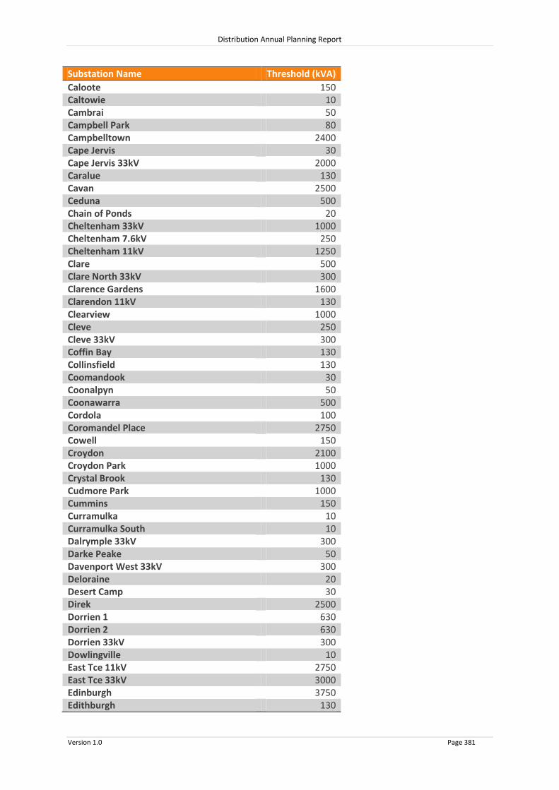
Distribution Annual Planning Report
Version 1.0 Page 381
Substation Name Threshold (kVA)
Caloote 150 Caltowie 10 Cambrai 50 Campbell Park 80 Campbelltown 2400 Cape Jervis 30 Cape Jervis 33kV 2000 Caralue 130 Cavan 2500 Ceduna 500 Chain of Ponds 20 Cheltenham 33kV 1000 Cheltenham 7.6kV 250 Cheltenham 11kV 1250 Clare 500 Clare North 33kV 300 Clarence Gardens 1600 Clarendon 11kV 130 Clearview 1000 Cleve 250 Cleve 33kV 300 Coffin Bay 130 Collinsfield 130 Coomandook 30 Coonalpyn 50 Coonawarra 500 Cordola 100 Coromandel Place 2750 Cowell 150 Croydon 2100 Croydon Park 1000 Crystal Brook 130 Cudmore Park 1000 Cummins 150 Curramulka 10 Curramulka South 10 Dalrymple 33kV 300 Darke Peake 50 Davenport West 33kV 300 Deloraine 20 Desert Camp 30 Direk 2500 Dorrien 1 630 Dorrien 2 630 Dorrien 33kV 300 Dowlingville 10 East Tce 11kV 2750 East Tce 33kV 3000 Edinburgh 3750 Edithburgh 130

Distribution Annual Planning Report
Version 1.0 Page 382
Substation Name Threshold (kVA)
Elizabeth Downs 2500 Elizabeth Heights 1000 Elizabeth South TF 1&2 1000 Eudunda 100 Evanston 2500 Findon 1000 Flinders Park 1000 Forreston 50 Freeling 150 Freeling North 190 Fulham Gardens 2100 Fullarville 10 Gawler Belt 1 630 Gawler Belt 2 630 Georgetown 10 Geranium 10 Gladstone 200 Glanville 800 Glencoe 50 Glenelg North 1000 Glossop 630 Glynde 1600 Golden Grove 3750 Gomersal North 50 Goolwa 1250 Gulnare 20 Gumeracha 15 Gumeracha Weir 10 Gumhaven 20 Hackham 1250 Hahndorf 250 Halbury 10 Hamley Bridge 130 Happy Valley 2500 Happy Valley SAW TF1 250 Harrow 1000 Hatherleigh 20 Hawker 50 Hay Flat 10 Henley South 2400 Hermitage 30 Hillcrest 2500 Hindley Street 11kV 2750 Hindley Street 33kV 3000 Holden Hill 2100 Hope Valley 1250 Houghton 150 Hoyleton 10 Hummocks 33kV 300 Ingle Farm 2100

Distribution Annual Planning Report
Version 1.0 Page 383
Substation Name Threshold (kVA)
Inverness 50 Jabuk 10 James Well 40 Jamestown 150 Jervois 310 Jervois Flat 1 150 Jervois Flat 2 150 Kadina 630 Kadina East 33kV 300 Kalangadoo 30 Kalangadoo West 50 Kanmantoo 250 Kapunda 1 630 Kapunda 2 630 Karoonda 50 Keith 11kV 630 Keith 33kV 300 Kent Town 2500 Kersbrook 50 Keswick 2100 Ki Ki 10 Kilburn 3150 Kilburn Bus A 1150 Kilburn South 1600 Kilkenny 2500 Kincraig 33kV 300 Kingscote 310 Kingston (SE) 150 Kingswood 3200 Kleins Point 150 Kongorong 50 Kumorna 50 Kybunga 10 Lakeside 630 Lameroo 100 Langhorne Creek 250 Largs North 1000 Lefevre 3200 Leigh Creek South 250 Linden Park 2500 Little Swamp 10 Lobethal 500 Lock 50 Lonsdale 10200 Loveday 750 Lower Mitcham 1000
Loxton 940 Lucindale 150 Lyndoch 190 Lyndoch South 30

Distribution Annual Planning Report
Version 1.0 Page 384
Substation Name Threshold (kVA)
Lyrup 250 MacGillivray 100 Maitland 250 Mallala 200 Mannum 33kV 300 Mannum Town 250 Marion Bay 50 Marrabel 150 McLaren Flat 1 630 McLaren Flat 2 630 McLaren Vale 250 Meadows 250 Melrose 30 Meningie 250 Milang 250 Millicent 500 Minlaton 100 Mobilong 33kV 300 Monarto South 600 Moonta 500 Moorkitabie 50 Morgan 50 Morphett Vale East 2400 Morphettville 1000 Mount Barker 3200 Mount Burr 20 Mount Gambier 33kV 300 Mount Gambier City 11kV 1000 Mount Gambier North 630 Mount Gambier West 1000 Mount Gunson 33kV 300 Mount Pleasant 100 Mount Schank 150 Murray Bridge North 1250 Murray Bridge South 1250 Mylor 190 Mypolonga 100 Myponga 500 Nairne 380 Nangwarry 150 Naracoorte 1250 Naracoorte East 630 Narrung 150 Neuroodla 250 New Osborne 500 New Richmond 2100 Nildottie 310 Ninnes 50 Noarlunga Centre 1000 North Adelaide 3200

Distribution Annual Planning Report
Version 1.0 Page 385
Substation Name Threshold (kVA)
North Unley 1000 Northfield 1000 Norwood 3150 Nuriootpa 630 Oaklands 2400 Orroroo 100 Padthaway 500 Palmer 20 Panorama 2500 Parafield Gardens 3200 Paralowie 1000 Parilla 50 Paringa 11kV 130 Paringa 33kV 630 Paskeville 50 Peake 20 Pellaring Flat 20 Penfield 11kV 2500 Penneshaw 80 Penola 150 Penola West 33kV 300 Peterborough 250 Piccadilly 150 Pinnaroo 100 Pinnaroo South 20 Playford 150 Plympton 1000 Point Boston 310 Polda 50 Poonindie 80 Port Adelaide 800 Port Adelaide North 2100 Port Augusta 1250 Port Augusta West TF1 630 Port Augusta West TF2 630 Port Broughton 250 Port Clinton 50 Port Germein 50 Port Giles 130 Port Julia 50 Port Lincoln 33kV 300 Port Lincoln City 1250 Port Lincoln Docks 630 Port Lincoln Marina 630 Port Noarlunga 2500 Port Pirie 1500 Port Pirie South 1880 Port Stanvac 3750 Port Vincent 100 Portee 30

Distribution Annual Planning Report
Version 1.0 Page 386
Substation Name Threshold (kVA)
Prospect 2100 Punyelroo 30 Pyap 630 Qualco 130 Queenstown 800 Quorn 130 Ramco 350 Rapid Bay 20 Rapid Bay 3.3kV 90 Renmark 1130 Riverton 150 Robe 250 Robertstown 50 Roonka 320 Rudall 30 Salisbury 3150 Salt Cliffs 30 Sandy Creek 150 Seacombe 2500 Seaford 630 Second Valley 30 Sheidow Park 1250 Sherlock 10 Smithfield West 1250 Snuggery Industrial 33kV 300 Snuggery Rural 33kV 300 South End 30 Spalding 100 Square Water Hole 250 Stansbury 130 Stirling East 630 Stirling North Old 130 Stirling North New 150 Stockwell 310 Stony Point 130 Strathalbyn 630 Strathalbyn East 500 Streaky Bay 250 Swan Reach 11kV 150 Swan Reach 33kV 300 Tailem Bend 33kV 300 Tailem Bend Town 150 Tantanoola 50 Tarlton 50 Tarpeena 320 Tea Tree Gully 2100 Teal Flat 150 Templers 33kV 300 Thebarton 2100 Tintinara 50

Distribution Annual Planning Report
Version 1.0 Page 387
Substation Name Threshold (kVA)
Tonsley Park 1500 Tumby Bay 250 Two Wells 630 Uley 50 Uley South 80 Uraidla 11kV 630 Uraidla 33kV 1250 Valente 20 Verdun 50 Victor Harbor 2500 Virginia 630 Waikerie 500 Walker Flat 100 Wallaroo 630 Warooka 250 Wasleys 100 Waterloo 33kV 300 Waterloo 11kV 30 Whitmore Square 2750 Whyalla City 1000 Whyalla North 150 Whyalla Stuart 1250 Whyalla Terminal 33kV 300 Williamstown 130 Williamstown South 190 Willunga 11kV 250 Willunga 33kV 380 Wilmington 50 Wirrabara Forest 50 Wirrabara South 10 Wirrina Cove 80 Wongyarra 10 Woodforde 2100 Woods Point 310 Woodside 500 Woodville 33kV 2000 Woodville 7.6kV 500 Woolpunda 750 Wudinna 11kV 200 Yankalilla 11KV 630 Yankalilla 33kV 630 Yankalilla Hill 20 Yongala 20 Yorketown 100