Attachment 4 - University Technology Office Advanced ... · satellite learning centers ASU UTO has...
42
Attachment 4 - University Technology Office Advanced Network Services, Design Standards And Construction Specifications Version 2.2 July 20, 2018
Transcript of Attachment 4 - University Technology Office Advanced ... · satellite learning centers ASU UTO has...

Attachment 4 - University Technology Office Advanced Network Services, Design Standards
And Construction Specifications
Version 2.2 July 20, 2018

ii
Table of Contents
1 GENERAL ........................................................................................................................ 6 2 CODES AND STANDARD REFERENCES ....................................................................... 7 3 REFERENCE DOCUMENTATION ................................................................................... 7
3.1 FCC Regulations ................................................................................................. 7 3.1.1 FCC Documentation ................................................................................... 7
3.2 NFPA Codes ....................................................................................................... 7 3.2.1 NFPA Documentation ................................................................................. 8
3.3 ANSI/TIA/EIA Telecommunication Building Wiring Standards ............................. 8 3.3.1 ANSI Documentation .................................................................................. 9
3.4 BICSI Methodologies ........................................................................................... 9 3.5 ANSI/NECA/BICSI 568-2001............................................................................... 9
3.5.1 BICSI Documentation ................................................................................. 9 4 DEFINITION OF TERMS, ACRONYMS AND ABBREVIATIONS ..................................... 9
4.1 Equipment Room (ER) ........................................................................................ 9 4.2 Entrance Facility (EF) .......................................................................................... 9 4.3 Telecommuncation Room (TR) ........................................................................... 9 4.4 Acronyms .......................................................................................................... 10
5 DESIGN STANDARDS ................................................................................................... 10 6 TELECOMMUNICATION ROOMS.................................................................................. 11
6.1 Telecommunication Room/Building Equipment Rooms ..................................... 11 6.2 General ............................................................................................................. 12 6.3 Location ............................................................................................................. 13 6.4 Electromagnetic Interference............................................................................. 13 6.5 Access… ........................................................................................................... 13
7 DESIGN ........................................................................................................................ 14 7.1 Architectural ...................................................................................................... 14 7.2 Size ................................................................................................................... 14 7.3 Walls ................................................................................................................. 14 7.4 Plywood Backboards ......................................................................................... 14 7.5 Ceiling Height .................................................................................................... 14 7.6 Treatment .......................................................................................................... 14 7.7 Ceiling ............................................................................................................... 14 7.8 Door .................................................................................................................. 14 7.9 Floor Loading .................................................................................................... 14 7.10 Signage ........................................................................................................... 15
8 ENVIRONMENTAL ......................................................................................................... 15 8.1 Contaminants .................................................................................................... 15 8.2 Heating, Ventilation and Air Conditioning (HVAC) ............................................. 15 8.3 Continuous Operation ....................................................................................... 15 8.4 Equipment Placement ....................................................................................... 15 8.5 Standby Operation ............................................................................................ 15
8.6 Operational Parameters ............................................................................... 15 8.7 Positive Pressure .............................................................................................. 15 8.8 Vibration ............................................................................................................ 15

iii
8.9 Other Mechanical Fixtures ........................................................................... 16 9 ELECTRICAL ....................................................................................................... 16
9.1 Lighting ........................................................................................................ 16 9.2 Power .......................................................................................................... 16 9.3 General 9.4 Equipment 110V Outlets .............................................................................. 16 9.5 Equipment 208V Outlets .............................................................................. 16 9.6 Emergency 110V and 208V Outlets ............................................................. 16 9.7 Convenience 110V Outlets .......................................................................... 16 9.8 Location of Power Conditioning Systems (UPS) .......................................... 17 9.9 Bonding and Grounding ............................................................................... 17
10 MISCELLANEOUS ............................................................................................ 20 10.1 Fire Protection ........................................................................................... 20 10.2 Water Infiltration......................................................................................... 20
11 CABLE PATHWAYS .......................................................................................... 20 11.1 General ...................................................................................................... 20 11.2 Ladder Rack .............................................................................................. 20 11.3 Sleeves ...................................................................................................... 20 11.4 Horizontal Pathway .................................................................................... 21 11.5 Vertical Pathway ........................................................................................ 21 11.6 Horizontal Backbone Inter-building Pathway ............................................. 21 11.7 Horizontal Backbone Intra-building Pathway ............................................. 21 11.8 General Telecommunication Room Design ............................................... 22
12 EQUIPMENT ROOMS AND SERVICE ENTRANCES ....................................... 22 12.1 General ...................................................................................................... 22
13 INTERIOR COMMUNICATION PATHWAYS ..................................................... 22 13.1 General ...................................................................................................... 22 13.2 Cable Tray ................................................................................................. 22 13.3 Conduit ...................................................................................................... 23 13.4 Intra-building Backbone Conduits .............................................................. 24 13.5 Outlet/Conduit Location ............................................................................. 24 13.6 New Construction Wall Outlet .................................................................... 24 13.7 New Construction Floor Outlet ................................................................... 24 13.8 Renovations ............................................................................................... 24 13.9 Sleeves ...................................................................................................... 24 13.10 Bonding and Grounding ........................................................................... 25
14 EXTERIOR COMMUNICATION PATHWAYS .................................................... 25 14.1 General ...................................................................................................... 25 14.2 Exterior Pathways ...................................................................................... 25 14.3 General ...................................................................................................... 25 14.4 Conduit ...................................................................................................... 25 14.4.1 Conduit Depth Requirements.................................................................. 26 14.5 Maintenance Vaults ................................................................................... 26 14.5.1 General ................................................................................................... 26 14.5.2 Conduit Entry Point ................................................................................ 26 14.5.3 Cover ..................................................................................................... 26
iv
14.5.4 Encasement ............................................................................................ 26 14.5.5 Conduit Orientation ................................................................................. 26 14.5.6 Trace Wire and Safety Tape ................................................................... 26 14.5.7 Separation from Other Utilities ................................................................ 26 14.5.8 Innerducts ............................................................................................... 27
14.6 Interior Hardware ............................................................................................. 27 14.6.1 Identifying Covers ................................................................................... 27 14.6.2 Concrete Strength ................................................................................... 27
14.7 Handhole ......................................................................................................... 28 14.7.1 General ................................................................................................... 28 14.7.2 Conduit Entry Points ............................................................................... 28 14.7.3 Covers .................................................................................................... 28 14.7.4 Identifying Covers ................................................................................... 28
15 BACKBONE CABLING ................................................................................................. 29 15.1 General ........................................................................................................... 29
16 HORIZONTAL CABLING .............................................................................................. 30 16.1 General ........................................................................................................... 30 16.2 Telecommunication Outlet Types, Configurations and Placement .................. 31
16.2.1 Identification ............................................................................................ 31 16.2.2 Standard Work Area Outlet ..................................................................... 32 16.2.3 TV Outlet ................................................................................................. 32 16.2.4 Standard Display Outlet .......................................................................... 33 16.2.5 Wall Phone Outlet ................................................................................... 33
17 SPECIAL SYSTEM DEVICES ...................................................................................... 34 17.1 Area Refuge Phone ......................................................................................... 34 17.2 Blue Light Phones ........................................................................................... 34 17.3 Elevator Phones .............................................................................................. 34 17.4 Wireless Access Point ..................................................................................... 34 17.5 Audio/Visual .................................................................................................... 34
18 TYPICAL OUTLET PLACEMENT ................................................................................. 34 18.1 Standard Office ............................................................................................... 34 18.2 Classrooms (Typical) ....................................................................................... 34 18.3 Conference Rooms ......................................................................................... 35 18.4 Student Living Spaces ..................................................................................... 35
18.4.1 Living Area/Living Room ......................................................................... 35 18.4.2 Bedroom ................................................................................................. 35 18.4.3 Open, Lounge, Common and Other Areas .............................................. 35 18.4.4 Tables, Desks and Study Carrels ............................................................ 35
19 TESTING, IDENTIFICATION AND ADMINSTRATION ................................................. 35 19.1 Testing ............................................................................................................ 35
20 ASU CABLE ID SCHEME ................................................................................... 36 20.1 Fiber Cable ID Scheme ........................................................................... 36 20.2 Copper Cable ID Scheme ....................................................................... 37
21 AMENDMENTS .......................................................................................................38,39

v
Table of Figures
1 FLOOR PLAN SYMBOLS LEGEND ............................................................................... 11 2 TELECOMMUNICATIONS ROOM (TYPICAL).......................................................... 12,13 3 TELECOMMUNICATIONS BONDING CONDUCTOR SIZE ........................................... 17 4 TELECOMMUNICATIONS GROUNDING BUSBARS .................................................... 18 5 TELECOMMUNICATIONS BONDING BACKBONE ....................................................... 19 6 4” CONDUIT SLEEVE – CABLE FILL TABLE ................................................................ 21 7 CABLE TRAY SUPPORT ............................................................................................... 23 8 EXAMPLE OF A LARGE & SMALL VAULTS ................................................................. 27 9 EXAMPLE OF A HANDHOLE ........................................................................................ 28 10 PATCH PANEL 12 INCH SERVICE LOOP................................................................... 30 11 FACEPLATE CONFIGURATIONS ................................................................ 30,31,32,33
Exhibits
A SHEET 1 – TYPICAL GENERAL NOTES AND SHEET INDEX B SHEET 2 – SYMBOL LEGEND, FILL TABLE, ABBREVIATIONS C SHEET 3 – FIBER CIRCUIT RISER AND LABEL DETAIL D SHEET 4 – BUILDING TO BUILDING FIBER DIAGRAM E SHEET 5 – TYPICAL FIBER RIER F SHEET 6 – TYPICAL COPPER RISER G SHEET 7 – TYPICAL GROUNDING RISER H SHEET 8 – TYPICAL PATHWAY RISER I SHEET 9 – TYPICAL OSP VAULT DETAILS J SHEET 10 – TYPICAL OSP CONDUIT DUCTBANK DETAILS K SHEET 11 – TYPICAL MDF-TELECOM ROOM DETAILS L SHEET 12 – TYPICAL SMALL IDF ROOM DETAILS M SHEET 13 – TYPICAL RACK ELEVATIONS N SHEET 14 – TYPICAL WALL ELEVATIONS – TR O SHEET 15 – APPROVED COMPONENT DETAILS P SHEET 16 – TYPICAL INSTALLATION DETAILS #1 Q SHEET 17 – TYPICAL INSTALLATION DETAILS #2 R SHEET 18 – TYPICAL INSTALLATION DETAILS #3 S SHEET 19 – SUBSTANTIAL COMPLETION CHECKLIST

6
1 GENERAL The purpose of the University Technology Office Advanced Network Services, Design Standards and Construction Specifications is to describe and specify the minimum building infrastructure required to support the voice, data and other special systems at ASU. Architects, engineers and designers should use these Design Standards and supplemental Design Typical Construction Sheets to develop specific project information and deliver the details of the project as Construction Documents. This document is based on industry standards and codes. This document does not replace any national or local standards, regulations or codes, but enhances them. If the standards and practices of the University Technology Office (UTO) exceed national or local standards, regulations or codes, ASU UTO’s practices shall take precedence.
The scope of this document includes the design and installation of Telecommunication Rooms (TRs), cabling distribution systems work area outlet locations, cable specifications, testing, documentation and administration. The cabling contractor is responsible for obtaining the CommScope SYSTIMAX Solutions specifications. This document is intended to serve as a guideline and therefore is subject to change on a project-by-project basis. It is the responsibility of the Design Team and/or contractor to identify inconsistencies in the specific project drawings and request clarification from ASU UTO Advanced Network Services designated point of contact.
In order to achieve and maintain the technology offering throughout the many campus’ and satellite learning centers ASU UTO has developed strategic partnerships with specific manufacturers as it relates to the telecommunications infrastructure. The following table outlines those partners and their product offering:
Manufacturer Product Type CommScope SYSTIMAX Solutions All Copper, Fiber, and Coax Products Chatsworth (CPI) Metal Products: Racks, Runway, Tray, Etc. B-Line Flextray Cable Tray Oberon WAP Enclosures Terra-Wave WAP Enclosures and Antennas Wiremold/Legrand Floor Boxes, Poke Thru’s & Raceway
Systems Circa Copper Cable Multi-Pair Protectors GaiTronics Emergency Phones Pyramid Industries Innerduct ITW LINX Lightening Protection Superior Essex OSP Copper (ANMW) & (ARMM) 3M Spice Closures Fluke Network Test Equipment for Fiber & Copper
It is further required that the installation contractor is certified in the state of Arizona to install and extend to ASU all performance and product warranties offered by the individual manufacturer.
7
Furthermore, the installation contractor must meet the minimum requirements:
• BICSI accredited RCDD on staff • CommScope SYSTIMAX Solutions D&E Certified Estimator & Project Manager on
Staff • 50% of onsite technical staff must be certified as BICSI &CommScope SYSTIMAX
Installers. • Proof of BICSI & CommScope SYSTIMAX certifications must be made available
upon request.
2 CODES & STANDARD REFERENCES The following codes and standards contain provisions that, through reference in this text, constitute provisions of document. At the time of publication the editions indicated were valid. All equipment, construction practices, design principles and installations must conform to the latest version of any or all of the following standards and codes, published by the following organizations, where applicable:
• Federal Communications Commission (FCC) • Institute of Electrical and Electronics Engineers, Inc (IEEE) • National Fire Protection Association (NFPA) • National Electrical Code (NEC) • American National Standards Institute (ANSI) • Telecommunications Industry Association (TIA) • Electronic Industries Alliance (EIA) • Building Industry Consulting Service International (BICSI) • National Electrical Contractors Association (NECA) • International Building Code (IBC) • International Existing Building Code (IEBC)
3 REFERENCE DOCUMENTATION All ASU UTO staff, architects, engineers, contractors and vendors involved in the design, installation, and specification of structured cabling systems must have access to the following referenced documentation. They will be held accountable to the standards set forth in this document. The standards, codes, and regulations referenced may have corrections, additions, technical service bulletins, and addendums that are not specifically called out in this section. In all cases, the latest versions are to be referenced regardless of versions stated in this document. Questions, problems or comments concerning this document or the referenced document should be directed to the University Technology Office.
3.1 FCC Regulations FCC Part 68 Regulations for connecting premise cabling and customer provided equipment to regulated networks.
3.1.1 FCC Documentation FCC Documentation is available at the following Web site: http://www.fcc.gov/Bureaus/Engineering_Technology/Documents/cfr/1999/47cfr68.pdf

8
3.2 NFPA Codes These NFPA documents are related to telecommunication:
• NFPA-70 National Electrical Code Chapter 8- Communication Systems • NFPA-71 Central Signaling Systems • NFPA-72 National Fire Alarm Code • NFPA-75 Fire Protection of Information Technology Equipment • NFPA-780 Lightning Protection Code • NFPA-101 Life Safety Code
3.2.1 NFPA Documentation NFPA documentation is available from the following:
National Fire Protection Association 1 Batterymarch Park Quincy, MA 02269-9101 Telephone: (617) 770-3000 Fax: (617) 770-0700
3.3 ANSI/TIA/EIA Telecommunication Building Wiring Standards (latest version) There are several documents that make up the ANSI/TIA/EIA Commercial Building Telecommunication Cabling Standards. These include:
• ANSI/TIA-568.0-D (2015) Generic Telecommunications Cabling for Customer
Premises- Deals with Topologies, Lengths, Installation Practices, Testing Methods, Fiber polarity etc.
• ANSI/TIA-568.1-D (2015) Commercial Building Telecommunications Cabling Standard- Deals with details of Entrance Facilities, Equipment rooms, Telecom Closets and Rooms, Enclosures, Backbone cabling, Horizontal Cabling, Work areas, MUTOA – ANSI/TIA-568-C.2 (2009) Balanced Twisted-Pair Telecommunications Cabling and Components Standards- Deals with the performance specification for components as well as channels for copper links. Defines category 5e, 6, 6e and 6A.
• ANSI/TIA-568-C.3-1 (2011) Optical Fiber Cabling Components Standard- Deals with the performance specification for components and polarity of fiber connections. Defines fiber performance specs for OM1, OM2, OM3, OM4, OS1 and OS2 cable.
• ANSI/TIA-568-C.4 (2011) Broadband Coaxial Cabling and Components Standard • ANSI/TIA-569-D-2015 Telecommunications Pathways and Spaces. • ANSI/TIA-570-C–2012 Residential Telecommunications Infrastructure Standard. • ANSI/TIA-606-B.1-2012 (2015) Administration Standard for Commercial
Telecommunications Infrastructure. (Addendum 1) • ANSI/TIA-607-C-2015 Commercial Building Grounding (Earthing) and Bonding for
Customer Premises • ANSI/TIA-758-B–2012 Customer-Owned Outside Plant Telecommunications
Infrastructure Standard • ANSI/TIA-862-B Intelligent Building Systems • ANSI/TIA-942-A-2012 Telecommunications Infrastructure Standard for Data
Centers. This standard specifies the minimum requirements for telecommunications

9
• ANSI/TIA-1005-A-2012 Industrial cabling Standard, deals with MICE (Mechanical, Ingress, Climate, EMI) and related issues
• ANSI/TIA-1152–2009 Requirements for Field Test Instruments and Measurements for Balanced Twisted-Pair Cabling.
• ANSI/ TIA-1179 (July 2010) Healthcare Facility Telecommunications Infrastructure Standard
3.3.1 ANSI Documentation ASNI documentation is available from the following:
Global Engineering Documents 15 Inverness Way East Englewood, CO 80112-5776 (800) 854-7179 ext. 7931
3.4 BICSI Methodologies
• BICSI Telecommunication Distribution Methods Manual (TDMM - latest edition) • BICSI Telecommunication Cabling Installation Manual (latest edition) • BICSI Customer Owned Outside Plant Design Manual (latest edition)
3.5 ANSI/NECA/BICSI 568-2001 Installing Commercial Building Telecommunication Cabling
3.5.1 BICSI Documentation BICSI documentation is available from the following:
BICSI 8610 Hidden River Parkway Tampa, FL 33637-1000 (800) 242-7405 http://www.bicsi.org
4 DEFINITION OF TERMS, ACRONYMS AND ABBREVIATIONS This section contains definitions of terms, acronyms, and abbreviations that have a special meaning or that are unique to the technical content of this document. The terms that are used in only one clause may be defined within, and at the beginning of, that clause.
4.1 Equipment Room (ER) An ER Room is a special purpose room designed to serve as a campus point of demarcation. An ER Room may service multiple TRs in a campus design. In large campuses, multiple ERs may be required and interconnected. This room will only contain Network & Telecommunication hardware and CATV. Other utilities and special systems must be pre-approved by ASU UTO Advanced Network Services.
4.2 Entrance Facility (EF) An EF is a special purpose room designed to serve a single building with multiple TRs. The EF may also contain the necessary equipment to function as a TR for the floor it is located on. This

10
room will only contain Network & Telecommunication hardware and CATV. Any other utilities must be approved by ASU UTO Advanced Network Services.
4.3 Telecommunication Room (TR) A TR is a special purpose room designed to serve a single floor. In buildings with multiple floors, TRs shall be vertically stacked to form a backbone pathway. The TR is the point in the Data, Voice and CATV infrastructure that the backbone and horizontal distribution systems are connected to each other. This room will only contain Network, Telecommunication and CATV hardware. Other utilities and special systems must be approved by ASU UTO Advanced Network Services.
4.4 Acronyms
• AFF Above Finished Floor • BICSI Building Industry Consultants Service International • CAT Category • CATV Community Antenna Television (cable television) • EF Entrance Facility • ER Equipment Room • HH Handhole • IDF Intermediate Distribution Frame • MDF Main Distribution Frame • MV’ Maintenance Vault • OSP Outside Plant • PBX Private Branch Exchange (Phone Switch) • QA Quality Assurance • SMB Surface Mount Box • TBB Telecommunication Bonding Backbone • TMB Telecommunication Mounting Board • TMBB Telecommunication Mounting Back Board • TO Termination Outlet • TR Telecommunication Room (Formally the IDF) • TGB Telecommunications Grounding Busbar • TMGB Main Telecommunication Grounding Busbar • TDMM Telecommunication Distribution Methods Manual (BICSI Publication) • UTO University Technology Office • UTP Unshielded Twisted Pair • WAP Wireless Access Point
See “Codes and Standards References” for additional codes and standards Acronyms. Or visit www.webopedia.com for additional definitions.

11
5 DESIGN STANDARDS Figure 1: Floor Plan Symbols Legend

12
6 TELECOMMUNICATION ROOMS 6.1 Telecommunication Rooms
6.2 General The following section will outline the location, design and pathway requirements for a typical Telecommunication Rooms (TR) or Entrance Facility (EF). These spaces are independent of Mechanical Spaces and do not fall under any of the requirements that define a Mechanical space.
Figure 2: Telecommunications Room (Typical)

13
6.3 Location EF and TR locations must meet the following requirements:
• Location shall be selected so that the room may be expanded. • Shall be located as close as practicable to the center core of the building to minimize
horizontal cable distance (Maximum cable length is 250’ from TR to TO.) • Shall be accessible through common-use corridors that will allow the delivery of
large cable reels and equipment and access for repairs 24x7. • In multiple floor applications, EF and TRs shall have all 4 walls vertically stacked.
The EF and TRs shall not be part of a server, mechanical, equipment, electrical, washroom, storage area, or a janitor closet. All room locations must be approved in writing by ASU UTO Advanced Network Services prior to construction.
6.4 Electromagnetic Interference The EF and TRs shall be located away from sources of electromagnetic interference. Special attention shall be given to electrical power supply transformers, motors and generators, x-ray equipment, elevator equipment, and induction devices.
6.5 Access Access to the Rooms shall be 24 hours-per-day, 365 days-per-year basis (24x7). Access shall be through common use corridors and not accessed by way of any other room. At a minimum

14
all doors to TR’s will be equipped with a lock and ISSAC access system if available. Preferably, they shall be on the UTO ISSAC segment.
7 DESIGN 7.1 Architectural
7.2 Size Rooms shall have a minimum inside dimension of 14ft x 16ft dependent on specific Telecommunication requirements. If these rooms require additional square footage based on additional requirements, the size shall be determined on a case-by-case basis. ASU UTO Advanced Netwrok Services must approve all room dimensions in writing.
7.3 Walls All four (4) walls shall be floor to deck and have a 2-hour fire rating.
7.4 Plywood Backboards All four (4) walls shall be covered with ¾ in. fire retardant plywood with fire rating stamp visible on all plywood. Plywood will be rated to meet applicable codes and must be LEED compliant. To reduce warping, fire-rated plywood shall be kiln-dried to maximum moisture content of 15%. Plywood will not be painted. Mount plywood 24” above finished floor (a.f.f.) and extend vertically. Top of plywood shall be level but shall not exceed 10’-0” a.f.f.
7.5 Ceiling Height The height between the finished floor and the lowest point of the ceiling should be a minimum of (14 ft).
7.6 Treatment Floors, walls, and ceiling shall be treated to eliminate dust. Finishes shall be light in color to enhance room lighting. Floor covering shall be sealed concrete.
7.7 Ceiling Room shall not have a false or drop ceiling to permit maximum use of cable pathways both vertically and horizontally. In such cases where fireproofing may be sprayed onto the exposed ceiling, the fireproofing shall be treated to mitigate airborne dust.
7.8 Door Doors shall be a minimum of (42 in) wide and (80 in) high, without doorsill, hinged to open outward (code permitting) or be removable. Consideration should be given to using double doors with a removable center-post. The door(s) shall be fitted with a lock, which is keyed and ISSAC access system if available.
7.9 Floor Loading The EFs shall be located on floor areas designed with a minimum floor loading of 4.8 kPa (100 lbf/ft2). The TRs shall be located on floor areas designed with a minimum floor loading of 2.4 kPa (50 lbf/ft2). The project structural engineer shall verify that concentrations of proposed equipment do not exceed the floor-loading limit.

15
7.10 Signage Signage, if used, should be developed within the signage plan of the building.
8 ENVIRONMENTAL 8.1 Contaminants The rooms shall be protected from contaminants and pollutants that could affect operation and material integrity of the installed equipment.
8.2 Heating, Ventilation and Air Conditioning (HVAC)
8.3 Continuous Operation HVAC shall be available on a 24 hours-per-day, 365 days-per-year basis. A stand-alone or dedicated unit shall be considered for all Telecommunication Rooms.
8.4 Equipment Placement HVAC unit shall not be located in the TR. When the HVAC unit must be located in the TR the location needs to be approved by ASU UTO Advanced Network Services.
8.5 Standby Operation If a standby power source is available in the building, consideration should be given to also connecting the HVAC system serving the Communications Rooms to the standby supply.
8.6 Operational Parameters The temperature and humidity shall be controlled to provide continuous operating ranges of 18 °C (64 °F) to 24 °C (76 °F) with 30% to 55% relative humidity. No special accommodations will be made for relative humidity for facilities in the Greater Metropolitan Phoenix Area.
A minimum rating of 10,000BTU will be used for typical TR/IDF. For MDF a minimum rating of 30,000BTU will be used. However, BTU rating requirements shall be calculated on a room-by- room basis due to the nature of the equipment that is being hosted and must be approved by ASU UTO Advanced Network Services prior to system design.
The ambient temperature and humidity shall be measured at a distance of 1.5 m (5 ft) above the floor level, after the equipment is in operation, at any point along an equipment aisle centerline.
8.7 Positive Pressure A positive pressure differential with respect to surrounding areas should be provided with a minimum of one air change per hour.
8.8 Vibration Mechanical vibration coupled to equipment or the cabling infrastructure can lead to service failures over time. A common example of this type of failure would be loosened connections. If there is a potential for vibration within the building that will be conveyed to the TR via the building structure, the project structural engineer should design safeguards against excessive TR vibration.

16
8.9 Other Mechanical Fixtures Mechanical fixtures (e.g., piping, ductwork, pneumatic tubing, electrical conduits) not related to the support of TR/EF shall not be installed in, pass through, under or enter the TR/EF. In addition, the area adjacent to the exterior of the TR/EF walls shall remain clear for cable pathways entering the TR/EF.
9 ELECTRICAL 9.1 Lighting Lighting shall be a minimum of 500 lx (50 foot candles) measured 1 m (3 ft) above the finished floor, mounted 12” minimum above the elevation of the cable tray. Light fixtures shall not be directly over the equipment racks. Light fixtures should be hung in parallel with the equipment racks in the front and back. Light fixtures must be independently supported from the building structure. Light fixtures shall not be mounted to, or supported by the cable tray. NOTE - Lighting fixtures should not be powered from the same electrical distribution panel as the TR/EF. Dimmer switches shall not be used and emergency lighting and signs should be properly placed such that an absence of primary lighting will not hamper emergency exit. Motion sensors are required for all TR’s.
9.2 Power EF, ER and TRs power shall be approved by ASU UTO Advanced Network Services.
9.3 General Minimum dedicated 120VAC and 208VAC circuits that are fed from a panel not located in the TR.
9.4 Equipment 110V Outlets TRs shall be equipped with a minimum of one dedicated 120V, 20A (L5-20R) circuit. The outlets should be above equipment racks depending on room configuration and mounted on Unistrut and supported by elevation kit. All outlets shall have a computer generated label affixed to it indicating the panel room number, panel ID and circuit number. ASU UTO Advanced Network Services may specify additional outlets on a case-by-case basis.
9.5 Equipment 208V Outlets TRs shall be equipped with a minimum of one dedicated 208V, 30A (L6-30R) circuit. The outlets should be above equipment racks depending on room configuration and mounted on Unistrut and supported by elevation kit. All outlets shall have a computer generated label affixed to it indicating the panel room number, panel ID and circuit number. ASU UTO Advanced Network Services may specify additional outlets on a case-by-case basis.
9.6 Emergency 110V and 208V Outlets These outlets will be requested by ASU UTO Advanced Network Services on a case-by-case basis. All outlets shall have a computer generated label affixed to it indicating the panel room number, panel ID and circuit number. ASU UTO Advanced Network Services may specify additional outlets on a case-by-case basis.

17
9.7 Convenience 110V Outlets EFs/ TRs shall be equipped with convenience outlet placed on each wall of the TR for uses other than network equipment (i.e. power tools, testing equipment). This outlet shall be run from a separate electrical panel. All outlets shall have a computer generated label affixed to it indicating the panel room number, panel ID and circuit number. ASU UTO Advanced Network Services may specify additional outlets on a case-by-case basis.
9.8 Location of Power Conditioning Systems (UPS) Where applicable, dedicated environmental control equipment, such as power conditioning systems, and UPS up to 30 kVA shall be permitted in the TR. All UPS equipment larger than 30kVA shall be located in a separate room. All UPS equipment will have a wall mounted primary feed disconnect switch and a power transfer switch that will be included in the design of the room. This must be approved in writing by ASU UTO Advanced Network Services.
9.9 Bonding and Grounding Provide Telecommunication Grounding/Bonding System in accordance with NFPA-70 Article- 250, ANSI-J-STD-607A, and ASU UTO Specifications using approved Grounding Hardware and methods.
Provide a suitable Telecommunication Bonding Backbone (TBB) that connects TMGB to other TGB’s utilizing a minimum 3/0 insulated copper bonding conductor and double-bolted, Compression style, Grounding Lugs using Table A below. In addition, provide an interconnecting-bonding conductor between telecommunication rooms and equipment rooms STD-607A. This conductor equalizes the potential between grounding planes within the telecommunication rooms and equipment room.
Figure 3: Table 1 – TBB/BCC conductor size vs length

18
Provide Telecommunication Main Grounding Busbar (TMGB), and Grounding Busbar (TGB) in Entrance Facilities (EF), Telecommunications Rooms (TR) and Equipment Server Room.
The Telecommunication Main Grounding Busbar (TMGB) installed in the EF/MDF shall be 20 inches long and 4 inches wide by ¼ inch thick with pre drilled NEMA bolt hole sizing, dual lug and spacing, example; Chatsworth Products, Inc. Busbar Assemblies w/ Lug Kit part number 40158-020. CADWELD Bonding method with a 3/0 AWG insulated copper bonding conductor should be used for connection to electrical ground. Alternate connection points must be approved by ASU UTO Advanced Network Services.
The Telecommunication Grounding Busbar (TGB) installed in the TR shall be 12 inches long and 4 inches wide by ¼ inch thick with pre drilled bolt hole sizing and spacing, Chatsworth Products, Inc. part number 40158-012. All TGB Connections should utilize 3/0 AWG insulated copper bonding conductor using a double-hole lug, bolted, compression style, grounding Lugs.
Figure 4: Telecommunication Grounding Busbars

19
All cable tray, ladder rack, access floors and telecommunication racks and/or cabinets contained within the ER/TR shall be grounded/bonded to the Busbar (TGB), per Table A. All connections to be made with double-hole lug, bolted, compression style, grounding lugs.
All armored fiber and copper riser/OSP cable to be grounded/bonded to the Busbar (TGB). All connections to be made with double-hole lug, bolted, compression style, grounding lugs.
The Telecommunication Grounding Systems shall have non-metallic labels attached to each busbar and bonding conductor. Refer to ANSI/TIA/EIA 606A for additional labeling requirements.
The labels shall be located on conductors as close as practicable (ie. ease of access to read the label) to their point of termination. The labeling scheme will be coordinated with ASU UTO Advanced Network Services prior to installation.
The use of heat shrink on ground lugs connections is strictly prohibited.
Chatsworth Products Required. (See Sample Communications Submittal Package)
Figure 5: Telecommunications Bonding Backbone Mid-Rise Building Example

20
10 MISCELLANEOUS REQUIREMENTS 10.1 Fire Protection Fire protection of the TR, if required, shall be provided as per applicable code. If sprinklers are required within the spaces, the heads shall be provided with wire cages to prevent accidental operation. Drainage troughs shall be placed under the sprinkler pipes to prevent leakage onto the equipment within the room. As required, consideration should be given to the installation of alternate fire-suppression systems, confirm requirements with ASU UTO Advanced Network Services.

21
10.2 Water Infiltration The TR shall be free of water or drain pipes not directly required in support of the equipment within the room.
11 CABLE PATHWAYS 11.1 General Conduits and sleeves should extend 4-6” into the TR. If the conduits or sleeves are subject to water intrusion they must drain away from the room and be watertight. All conduits and sleeves must have the ends plugged upon installation. Basket tray shall not be run through walls. Conduits and sleeves must have bushings installed at all ends and at all pull boxes. The contractor responsible for the installation of the pathway system is also responsible for providing segmented pull strings. In hard lid or inaccessible ceiling spaces the use of conduit is required. Final design of the Telecommunication pathway must be approved by ASU UTO Advanced Network Services.
Conduit pathways built for telecommunication cabling have more stringent bending and pull box requirements than electrical cabling and must be adhered to (i.e. a telecommunications conduit can have no more than 180 degrees of cumulative bends between pull points).
11.2 Ladder Rack The ladder rack shall be installed around the inside perimeter of the TR room for the distribution of communication cabling. A ladder rack shall also be installed over the top of any free-standing racks with an overhead elevation kit. The runway shall be mounted 7’6” from finished floor to the bottom of the tray. There shall be no other equipment, lights, conduits, fixtures etc. attached to, mounted on, running through or on the ladder rack except those needed to support the ladder rack systems or those approved by ASU UTO Advanced Network Services, i.e. power distribution to support Network equipment.
• An 18” ladder rack (typical) will be installed in the ER/MDF. • A 12” ladder rack (typical) will be installed in the TR/IDF. • Ladder Rack may not be run through walls.
Chatsworth Products Required: (See Sample Communications Submittal Package)
11.3 Sleeves/Conduits Cable Fill The following table reflects maximum allowable cable quantities for (1) 4” conduit per ASU UTO 40% Fill ratio. The installing contractor is responsible to calculate actual cable fill measurements using cross section of actual conduit path and cable being installed in accordance with ANSI/TIA- 568 and ANSI/TIA-569 standards.
Cable Fill requirements are to be maintained for all sleeves consistent with size and rating of wall which is being penetrated.
Cable Fill requirements are to be maintained for all conduit runs consistent with size of conduit. This includes interior and exterior runs.
Figure 6: 4” Conduit/Sleeve - Cable Fill Table

22
Cable Manufacturer Cable Details O.D. (Inches) Qty of Cables @ 40% Fill CommScope Cat 6 UTP 2071 .226 148 CommScope Cat 6A FTP 2291 .276 99 CommScope Cat 6A UTP 2091 .285 92 CommScope RG-6 90% 2276V .237 135 CommScope 12/12 Armor Fiber .53 24
SPSX 25-pair CMP .43 40 CommScope 48-SM Armor Fiber .83 11
SPSX 100-pair ARMM .89 9 11.4 Horizontal Pathway The quantity of horizontal sleeves installed in each TR/EF for horizontal cabling shall be a minimum of four (4) EZ Path 44 Series raceways. The raceways shall be a minimum 8’-0” AFF to the bottom of the assemblies. Assemblies that are installed above 9’-0” AFF must have vertical ladder racking installed from the bottom of the assembly to the top of the cable tray for lashing of cables in the vertical run. The final quantity of EZ Path 44 Series assemblies will be based on the total number of cables that are routed to each TR. For new construction projects there must be a minimum of (1) spare assembly left empty for future growth at the time the project is complete and turned over to ASU.
11.5 Vertical Pathway In a multi-story building where TRs are stacked to form a riser, a minimum of six (6) EZ Path 44 Series assemblies shall be installed between the stacked TRs. Reduced quantities of riser conduits must be submitted to ASU UTO for approval prior to final design.
11.6 Horizontal Backbone Inter-building Pathway The horizontal backbone pathway shall consist of a minimum of six (6) 4” conduits between the EF/MDF of each building and the nearest designated maintenance vault servicing that facility. Cable tray can be used for Inter-building Backbone distribution only with the use of properly sized innerduct or by the installation of a physical separation for the protection of the Backbone cables from general cable installation.
11.7 Horizontal Backbone Intra-building Pathway • If the TRs are not vertically stacked on the EF/MDF, backbone pathway shall consist of
a minimum of six (6)-4” conduits installed between the EF/MDF of the building and each TR. All conduits and inner-ducts shall contain a mule tape with footage makers. In multi- story building where TRs are stacked to form a riser, a minimum of six (6) 4” conduits shall be installed between the EF/MDF and the first TR in the stack. ASU UTO Advanced Network Services must approve use of cable tray as a backbone distribution system.
11.8 General Telecommunication Room Design Telecommunication Room design shall follow BICSI TDMM design recommendations. ASU UTO Advanced Network Services must approve all final TR design. A detailed

23
telecommunication drawing shall be forwarded for approval by ASU UTO Advanced Network Services.
12 EQUIPMENT ROOMS AND SERVICE ENTRANCES 12.1 General Equipment Rooms / PBX and Service Entrance Rooms shall be located and designed on a case-by-case basis with ASU UTO Advanced Network Services.
13 INTERIOR COMMUNICATION PATHWAYS 13.1 General The Interior Communication and Special Systems Pathways shall provide a distribution system for all system cabling that will be served by the building. The pathways for a building may include all or some of the following, cable tray, continuous conduit systems, conduit stubs, sleeves, and cable hangers. All pathways must be approved by ASU UTO Advanced Network Services prior to design completion. Interior pathway design shall follow all BICSI TDMM design recommendations and TIA568-B, TIA569-A and NEC Article 200 standards. A detailed T1 and Pathway Logical drawing shall be required for all pathway plans.
13.2 Cable Tray A continuous cable tray system shall be installed on each floor as required. Installation methods will be consistent with those outlined in the NEMA VE-2 Cable Tray Installation Guidelines and the manufacturer’s specific installation requirements as well as the following:
The tray shall be a basket/mesh style with a minimum size of 12" W x 4" D. The cable tray shall be supported by a trapeze style support system with spans of 6’-0”. A solid bottom liner shall be installed in all open areas where tray elevation is at or below 8’-0” A.F.F. All cable tray shall be grounded per manufacturer’s specification. The use of “T” support is prohibited.
Chatsworth or B-Line Products Required: (See Sample Communications Submittal Package)
Figure 7: Cable Tray Support

24
Floors with fewer TOs than (50) may be supported with an approved “J” Hook solution with authorization from ASU UTO Advanced Network Services. When making turn and elevation changes the appropriate tray accessories, having the proper bend radius, must be used. For access to, and installation of, cables in the cable tray, the following clearances are required around the cable tray. The cable tray system shall have 1’-0” clearance measured from the top most surface of the tray. Access from the sides shall be 6" to 1’. Access to the cable tray from below shall be unobstructed its entire length. There shall be no other equipment, lights, conduits, fixtures etc. attached to, mounted on, installed through or on the cable tray or the support system except those needed to support the tray systems. Cable tray shall not be installed through walls. The tray shall stop at all walls and sleeves or conduits shall be installed. The tray shall continue on the other side of the wall as required. Support system for tray shall be detailed in submittals.
13.3 Conduit • Sizes indicated for conduits are trade sizes in all cases. Conduits shall have an
insulated bushing installed prior to the installation of telecommunications cabling. Conduits must have the ends plugged upon installation to keep debris from entering them. Conduit shall be installed in the most direct route possible, usually parallel with building lines. Conduit shall not contain continuous sections longer than 100 feet. If lengths total more than 100 feet, pull points or pull boxes shall be inserted. Conduit shall

25
have no more than 180 degrees of cumulative bends between pull points or more than 90 degrees of bends at any one point. Electrical Metallic Tubing shall be electro- galvanized steel. Conduit will be at 40% capacity of the conduits maximum fill. (See ASU UTO Advanced Network Services to request specifications section for conduit
detail.)
13.4 Intra-building Backbone Conduits See TR pathway requirements.
13.5 Outlet/Conduit Location
13.6 New Construction Wall Outlet Conduit stubbed above ceiling shall be a minimum of 1” with bushing. Each 1” conduit will service only one wall outlet location. (NO DAISY CHAIN) The conduit will be terminated in a 4” x 4” x 2.75” deep metal box with a pull string. The box shall be fitted with a single gang mud ring or a double gang mud ring when applicable.
Outlets are (typically) located at the following heights to top of wall outlet:
Desks 18” A.F.F. Above Counter 42” A.F.F. Cubicle Kick-plate Wall Phones 48” A.F.F. Room Scheduler 48” A.F.F. Display 60” - 84” A.F.F. Courtesy Phone 48” A.F.F. Touch Panel 48” A.F.F. WAP Above Ceiling
13.7 New Construction Floor Outlet Conduit from the cable tray to a typical floor outlet shall be a minimum of 1” for data and 1.25” for audiovisual. Each conduit will service only one outlet within one floor box location. (NO DAISY CHAIN) Confirm all floor outlets meet Fire Code and will accommodate CommScope SYSTIMAX inserts, bezels and/or faceplates.
13.8 Renovations For areas being renovated, the minimum requirement is for horizontal wiring to be properly supported and secured in the work area in either surface raceway, communication power pole raceway, enclosed within the wall or furniture and not exposed to possible damage. The cable shall be supported from cable tray to outlet location by CAT 6 approved cable hangers mounted a minimum of 6 inches above the ceiling at a maximum distance of 5’ between hangers.
13.9 Sleeves Sizes indicated for sleeves are trade sizes in all cases. Sleeves shall have an insulated bushing installed prior to the installation of telecommunications cabling. Sleeves must have the ends plugged upon installation to keep debris from entering them. Sleeves used at wall transition points for cable tray systems shall be 4 inches in diameter. Quantity of sleeves shall be equal to the cable capacity of the cable tray. Sleeves for distribution of horizontal cable in renovated areas not having conduits to the cable tray shall be sized so that when all cables have been installed at the completion of the project, the sleeve will be at 40% capacity of the

26
sleeves maximum fill. Sleeves must always be installed to maintain the rating of the wall they are penetrating.
Sleeves shall be installed using UL listed methods that maintain the rating of the wall or floor being penetrated. The minimum sleeve size installed for any penetration shall be 2 inches except when using STI Grommet for single cable interstitial adds.
13.10 Bonding and Grounding All ladder rack, cable tray and conduits shall be bonded to the TGB in the TR.
14 EXTERIOR COMMUNICATION PATHWAYS 14.1 General The Exterior Communication Pathways shall provide a campus distribution system for all system cabling that will be served by the building. The pathways for a campus distribution system may include all or some of the following; maintenance vault, Handhole, inner-duct, conduit, multi-cell conduits. All pathways must be approved by ASU UTO Advanced Network Services prior to implementation. Exterior pathway design shall follow all BICSI TDMM and BICSI Customer Owned Outside Plant Design Manual design recommendations and TIA568B and 569A standards. ASU UTO Advanced Network Services must approve all final design. A detailed telecommunication drawing and pathway logical drawing will be required.
(Conduit pathways built for telecommunication cabling have more stringent bending and pull box requirements than electrical cabling and must be adhered to (i.e. a telecommunications conduit can have no more than 180 degrees of cumulative bends between pull points).
14.2 Exterior Pathways
14.3 General Sizes indicated for conduits and innerduct are trade sizes in all cases. For quantities see Backbone Inter-Building section.
14.4 Conduit
• All conduits shall be a minimum of 4 inches for inter-building pathway. • Conduits must have the ends plugged upon installation to keep debris from entering
them. • Conduit lengths shall contain no continuous sections longer than 300 feet. If conduit
lengths total more than 300 feet, pull points shall be provided. • Conduit shall have no more than 180 degrees of cumulative bends between pull points
or more than 90 degrees of bends at any one point. All bends must be long, sweeping bends with a radius not less than six times the internal diameter of conduits 50 mm (2 in) or smaller, or ten times the internal diameter of conduits larger than 50 mm (2 in). 48 inches sweeps preferred.
• The use of pull boxes for 90 degree bends is prohibited. • All conduits must be proven with a mandrel prior to turning over to ASU UTO. • All ends of conduit must be reamed.

27
• All conduits entering a building must be pitched to drain away from the building to avert water intrusion. To prevent conduit shearing, conduits entering through walls shall be metallic and extend to undisturbed earth, particularly where such backfill is susceptible to load bearing tension.
• All conduits that do not have inner-duct shall be threaded with mule tapes with footage markers.
• Rigid Galvanized Steel Conduit shall be hot-dipped galvanized steel, including threads. Extra-Heavy wall conduit: Schedule 80, constructed of polyvinyl chloride, rated for use with 90 degree C conductors, and UL listed for direct burial and normal above ground use.
• Heavy wall conduit: Schedule 40, constructed of polyvinyl chloride, rated for use with 90 degree C conductors, and UL listed for direct burial and concrete encasement.
• Conduit will be at 40% capacity of the conduits maximum fill. • (See ASU UTO Advanced Network Services to request the specifications for exterior
conduit detail)
14.4.1 Conduit Depth Requirements Top of conduit must be buried at least 24 inches below finished grade.
14.5 Maintenance Vaults (Manholes)
14.5.1 General Joint Use Maintenance Vaults (MVs) are permitted. The vaults shall be 4’ x 6’ minimum.
14.5.2 Conduit Entry Points Conduits entering the MV are to be placed at opposite ends of a MV.
14.5.3 Covers Covers shall always be round and centrally located on single cover maintenance vault. Frames and covers used in roads or driveways shall be rated to withstand vehicular traffic. For MV over 3.7 m (12 ft) long, follow these guidelines:
• Between 3.7 m (12 ft) and 6 m (20 ft) use two covers. • Over 6 m (20 ft), use three covers.
14.5.4 Encasement All underground conduits shall be slurry capped sealed.
14.5.5 Conduit Orientation Manufactured conduit spacer shall be used for all conduits in the duct bank so conduits can maintain the same orientation at all points of access. The installer shall provide photographs and a site inspection to UTO Advanced Network Services.
14.5.6 Trace Wire and Safety Tape Telecommunication pathways underground shall have a trace wire for locating the route and an identifying tape to reduce the risk of damage if excavation intersects the conduit.
14.5.7 Separation from Other Utilities Power up to 1KVA:
• 12 in. of well- packed earth • 4 in. of masonry

28
• 3 in. of concrete Gas, Oil, Water, etc.:
• 12 in. when parallel • 6 in. when crossing
14.5.8 Innerducts
• Innerducts shall have both ends plugged upon installation. • All innerducts shall be threaded with mule tapes with footage markers. • Innerduct shall not be directly buried or concrete incased as a replacement to conduits. • All innerducts shall be marked with a unique identifier indicating that origin and
destination. • There shall be a minimum of 3 - 1 ¼ Inches ribbed, orange, PVC innerduct installed per
4 inch conduit. (Typical)
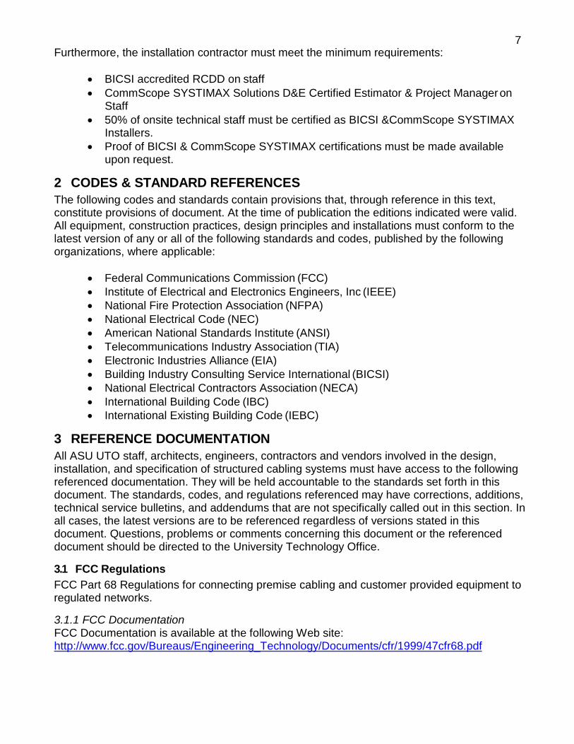
14.6 Interior Hardware All hardware in MVs must be galvanized. MVs shall be equipped with the following:
• Bonding inserts and struts for racking. • Pulling eyes at least 22 mm (7/ 8 in) in diameter. • A sump drywell of at least 200 mm (8 in) in diameter. • An entry ladder (required). • Appropriate grounding points.
14.6.1 Identifying Covers All covers shall have COMMUNICATIONS pre-marked on the cover for easy identification.
14.6.2 Concrete Strength The strength of concrete used for MVs shall be at least 24 kPa (3500 psi). NOTE: Stronger concrete may be stipulated in certain installations.
Figure 8: Examples of a Large & Small Vault
29
14.7 Handhole
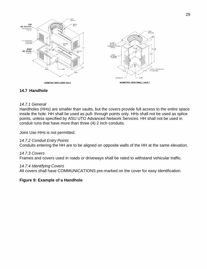
14.7.1 General Handholes (HHs) are smaller than vaults, but the covers provide full access to the entire space inside the hole. HH shall be used as pull- through points only. HHs shall not be used as splice points, unless specified by ASU UTO Advanced Network Services. HH shall not be used in conduit runs that have more than three (4) 2 inch conduits.
Joint Use HHs is not permitted.
14.7.2 Conduit Entry Points Conduits entering the HH are to be aligned on opposite walls of the HH at the same elevation.
14.7.3 Covers Frames and covers used in roads or driveways shall be rated to withstand vehicular traffic.
14.7.4 Identifying Covers All covers shall have COMMUNICATIONS pre-marked on the cover for easy identification.
Figure 9: Example of a Handhole

30
15 BACKBONE CABLING 15.1 General Backbone cabling is the media over which Voice, Video, Data, Audio, Community antenna television (CATV) signals will be transmitted to the TRs. The media used for the transmission of the signals will be copper, fiber and coax. Backbone cables are broken into two types, inter- building and intra-building. Inter-building cabling has very strict requirements when entering a building. Cable insulation type, lightning protection and termination methods are important considerations when designing outside plant (OSP) cabling. CIRCA lightning protection solutions shall be utilized on all copper multi-pair cables and all copper and fiber optic cables will be grounded.
Sizing of backbone cabling for support of a building is directly related to the building’s functions both during initial occupancy and future use. There is no generic backbone installation that will fit all applications. Design of the building’s backbone cabling will be on a case-by-case basis. Generally, Optical Fiber, High Pair Count Copper and Coaxial cable will be installed for backbone applications.
Backbone cable design shall follow all current BICSI TDMM design recommendations and TIA568B standards. ASU UTO Advanced Network Services must approve all final design. A detailed Communication site plan and Backbone logical drawings will be required for all Backbone cabling Plans.
Product Requirement: (See Sample Communications Submittal Package)
• OSP & Riser Fiber CommScope SYSTIMAX Armored LazrSpeed (50mm Multi- mode) & SYSTIMAX (Single-mode)
• OSP Copper Superior Essex ANMW Armored • Riser Copper Superior Essex ARMM • OSP & Riser Coax CommScope SYSTIMAX .5/.75

31
• Fiber Terminations – CommScope SYSTIMAX 360G2 12ct LC MM and LC SM cassettes with pigtails.
• Fiber Optic Shelf (LIU) – Rack mount enclosures shall be used for fiber terminations, sized accordingly
• CommScope SYSTIMAX VisiPatch 360 shall be used for Copper OSP & Riser terminations
• 110 Blocks shall be used for transition from wall to CommScope SYSTIMAX VisiPatch in a rack.
16 HORIZONTAL CABLING 16.1 General The following will describe the minimum work area outlet requirements for areas such as; a standard office, classroom, conference room, special locations and residence halls. The use of plenum cable is required unless home run conduits are installed in ASU facilities. The exact placement and quantities of outlets and pathways must be approved by ASU UTO Advanced Network Services.
Detailed communications floor plans for backbone cable design shall follow all current BICSI TDMM design recommendations and TIA568B standards. ASU UTO Advanced Network Services n must approve all final designs in writing.
In general, install one (1) TO with (2) CAT6 cable in each office on the wall opposite of the door. Larger offices for Director Level and above should receive two (2) TOs.
A minimum of one duplex electrical outlet should be installed within 16 inches, but not closer than 8 inches, of every work area outlet.
Cable ID label shall be a minimum 4 inches from termination point at patch panel and T.O.s.
Figure 10: PATCH PANEL 12 INCH SERVICE LOOP

32
CAT6 cable shall be installed in horizontal manager 12 inches down from management bar and 12 inches up to patch panel.
16.2 Telecommunication Outlet Types, Configurations and Placement
(To be comprised of all CommScope SYSTIMAX components. See Sample Communications Submittal Package)
16.2.1 Identification Identification of cabling, pathways and hardware shall conform to TIA 606-A. The labeling scheme for the structured cabling system shall be submitted to ASU UTO Advanced Network Services for approval and inclusion in all matrices for building operations prior to trim/finish. Faceplate, insert and dust cover shall be same color. Dust covers shall be installed on all faceplates.
Figure 11: Faceplate Configurations

33

34
16.2.2 Standard Work Area Outlet A Standard work area outlet is comprised of two CommScope SYSTIMAX 4-pair Category 6 twisted pair cables, inserted into a single gang 3-port faceplate. The faceplate, insert, and dust covers shall be the same color. Dust covers shall be installed on all jacks and empty ports of the faceplate. The jack identifier designated window (label holder) shall be printed or typed in black on white.
16.2.3 Standard TV Outlet A standard TV outlet is comprised of (1) 4-pair CommScope SYSTIMAX Category 6 twisted pair cable and (1) quad-shielded RG-6 or RG-11 coax cable depending on length from TR to distribution point. The RG-6 shall be used for lengths less than 200’ and the RG-11 shall be used for lengths over 200’.

35
16.2.4 Display Outlet A Display outlet is comprised of (1) CommScope SYSTIMAX 4-pair Category 6, blue jacketed cable and (1) CommScope SYSTIMAX 4-pair Category 6A/FTP, green jacketed cable, inserted into a single gang 3-port faceplate. The faceplate, insert, and dust covers shall be the same color. Dust covers shall be installed on all jacks and empty ports of the faceplate. The jack identifier designated window (label holder) shall be printed or typed in black on white.
16.2.5 Wall Phone Outlet A Wall Phone outlet is comprised of one CommScope SYSTIMAX 4-pair Category 6 twisted pair voice cable. All wall phone locations shall be ADA compliant. The faceplates shall be a plastic single gang type.

36
17 SPECIAL SYSTEM DEVICES 17.1 Area Refuge Phone The phone outlet is comprised of one CommScope SYSTIMAX 4-pair Category 6 twisted pair cable. All locations shall be ADA compliant. The cable shall be terminated on a TIA-568B CAT6 jack by the cabling contractor responsible for the installation.
17.2 Blue Light Phones The phone outlet is comprised of four (4) OSP rated CommScope SYSTIMAX 4-pair Category 6 twisted pair cables. Ensure blue lights are placed within 250’ of Telecommunications Room. The cables shall be terminated on a TIA-568B CAT6 jack by the cabling contractor responsible for the installation. A 1 ¼ inch conduit shall be installed between the building and Blue Light Stanchion. Verify if UTO wants surge protection on each instance of a Blue Light Location prior to installation.
17.3 Elevator Three CommScope SYSTIMAX 4-pair Category 6 twisted pair cables, per cab, located at the Elevator Control Room.
The cable shall be terminated on a TIA-568B CAT6 jack by the CommScope certified cabling contractor responsible for the installation.
17.4 Wireless Access Point A wireless access point is comprised of (2) CommScope SYSTIMAX 4-pair Category 6A twisted pair cables. A Wireless enclosure shall be installed as required and terminated cables shall be housed in CommScope SYSTIMAX M101SMB surface mount boxes. The locations for these cables shall be determined by ASU UTO. Contact and arrange for these engineering services on a per project basis and coordinate closely with ASU UTO Advanced Network Services.
17.5 Audio/Visual Audio/Visual devices shall have a minimum of (1) CommScope SYSTIMAX 4-pair Category 6A shielded cable, Color Green, as required. Most often they are accompanied by a CommScope SYSTIMAX 4-pair Category 6 twisted pair cable. Coordinate closely with ASU UTO Advanced Network Services on all audiovisual design scenarios.
18 TYPICAL OUTLET PLACEMENT 18.1 Standard office Each office shall have a minimum of one TO, on opposite wall of entry. The TO should be three feet from the back wall (furthest from the door) and shall contain a minimum of (2) CommScope SYSTIMAX 4-pair Category 6 cables.

37
18.2 Classrooms (Typical) The specific cabling requirements shall be determined on a case-by-case basis. However, please us the following as a classroom base; one TO located in the ceiling for video projection and camera containing (2) Category 6 cables. One floor box at the front of the classroom containing up to (6) Category 6 cables for lectern. One TO containing (2) Category 6 cables, per location, for wireless access points or as required.
18.3 Conference Rooms The specific cabling requirements shall be determined on a case-by-case basis. However, please us the following as a classroom base; TO located in the ceiling for video projection and camera containing (2) Category 6 cables. Floor box beneath conference room table containing up to four Category 6 cables. TO containing (2) Category 6 cables per location for wireless access points. Lab Areas, Computer Rooms and Other The specific cabling requirements shall be determined on a case-by-case basis.
18.4 Student Living Spaces
18.4.1 Living Area / Living Room Each living area or room shall have a minimum of (1) outlet with coax cable and one work area outlet with (1) Category 6 cable.
18.4.2 Bedroom There shall be (1) CommScope SYSTIMAX CAT6 for voice per room and (1) CommScope SYSTIMAX CAT6 for data per pillow.
18.4.3 Open, Lounge, Common and Other Areas The specific cabling requirements shall be determined on a case-by-case basis.
18.4.4 Tables, Desks and Study Carrels The specific cabling requirements shall be determined on a case-by-case basis.
19 TESTING, IDENTIFICATION AND ADMINISTRATION 19.1 Testing Testing of Copper UTP cables shall conform to the requirements of ANSI/TIA 568-C Standards. 100% of installed cables must pass a Permanent link test for Cat6, CAT6A, or Cat6A/FTP respectfully with a minimum of 3dB headroom. Permanent link for CAT6A/FTP OSP cable when cabling is installed in conduit from TR to T.O. shall be adjusted. When this specific pathway instance exists the minimum requirement shall be reduced to 1dB of headroom.
Testing of Optical Fiber cables shall conform to the requirements of TIA 568-C Tier II extended test regimen. This includes OTDR Traces to be provided for all fiber testing; bi-directional and power meter.

38
Fluke DSX-8000 or approved equivalent is recommended for Copper/Fiber cable tests. Fluke DTX series will be allowed thru June 30, 2018. All results to be submitted in original Linkware format. Summary and individual Graphical results of all tested cables/strands in project scope must be submitted to qualify as a complete package.

39
306B-X
Building #- Cable #
20 ASU CABLE ID SCHEME 20.1 Fiber Cabling Scheme:
Intra-building:
Example: From ER to TR, Building # - Cable #.
306B-2, 306B-3, 306B-4, ETC…….
Inter-building:
Example: From - To, Building # - Building # - Cable #.
In Building #170, Cable shall read, 170-168-1.
In Building #168, Cable shall read, 168-170-1.
LIU Labeling:
Example:
ROOM # 250U1, LIU #1 = 250U1-L1 ROOM # 250U1, LIU #2 = 250U1-L2 ROOM # 250U1, LIU #3 = 250U1-L3
250U1-L1 306B-X
ROOM # - LIU # Building #- Cable #
168-170-X
Building #-Building #-Cable #

40
uildin
- C
#-
20.2 Copper Cabling Scheme:
Intra-building:
Example: From ER to TR, Building #, Floor #, Cable #, Pair Count
306B-2-2-1-100, 306B-3-3-1-100, 306B-4-4-1-100, ETC
Inter-building:
168-170-1-001-1-100
Building #- Building #- Floor #- Cable #- Pair Count
Example: From – To, Building # - Building # - Floor# - Cable # - Pair Count
In Building #168, Cable shall read, 168-170-1-001-1-100. In Building #170, Cable shall read, 170-168-1-001-1-100.
306B-1-001-1-100
B g #- Floor # able Pair Count

41
21 AMENDMENTS Amendment: 7/01/2017
Version 2.0 issued. A complete revision of all sections, including verbiage updates and substantial changes to tables and example diagrams.
Amendment: 7/01/2017
UTO typical detail sheets have been added as a compliment to the Design Standard. (19) Sheets that identify installation details, component details, typical riser diagrams, and other details for Telecommunications and Structured Cabling Design and Installation. These detail sheets are to be used in conjunction with the standard to assist the Design Teams and the Installation Contractors to meet the needs of ASU. The following sheets have been added as exhibits:
Exhibits
A SHEET 1 – TYPICAL GENERAL NOTES AND SHEET INDEX B SHEET 2 – SYMBOL LEGEND, FILL TABLE, ABBREVIATIONS C SHEET 3 – FIBER CIRCUIT RISER AND LABEL DETAIL D SHEET 4 – BUILDING TO BUILDING FIBER DIAGRAM E SHEET 5 – TYPICAL FIBER RIER F SHEET 6 – TYPICAL COPPER RISER G SHEET 7 – TYPICAL GROUNDING RISER H SHEET 8 – TYPICAL PATHWAY RISER I SHEET 9 – TYPICAL OSP VAULT DETAILS J SHEET 10 – TYPICAL OSP CONDUIT DUCTBANK DETAILS K SHEET 11 – TYPICAL MDF-TELECOM ROOM DETAILS L SHEET 12 – TYPICAL SMALL IDF ROOM DETAILS M SHEET 13 – TYPICAL RACK ELEVATIONS N SHEET 14 – TYPICAL WALL ELEVATIONS – TR O SHEET 15 – APPROVED COMPONENT DETAILS P SHEET 16 – TYPICAL INSTALLATION DETAILS #1 Q SHEET 17 – TYPICAL INSTALLATION DETAILS #2 R SHEET 18 – TYPICAL INSTALLATION DETAILS #3 S SHEET 19 – SUBSTANTIAL COMPLETION CHECKLIST
Amendment: 9/11/2017
19.1Testing – Revised statement to clarify what situation qualifies the reduced headroom expectation.
P SHEET 16 – TYPICAL INSTALLATION DETAILS #1 – Replaced Detail #7 example with the new Heat Shrink example. The Heat Shrink Example will serve as the new detail for security cameras, touch panels, room schedulers, and some WAP installations. R SHEET 18 – TYPICAL INSTALLATION DETAILS #3 – Replaced Enclosure 1065 with Enclosure 1042. Added Enclosure Type 1047 to accommodate the Cisco 2800 series WAP’s. Changed “Detail Titles” to include Cisco WAP Part # that each enclosure type supports.

42