ATTACHMENT 2 2006 RADIOACTIVE EFFLUENT RELEASE …
168
D Serial No. 07-0244 )ocket Nos. 50-245 50-336 50-423 •ense Nos. DPR-21 DPR-65 NPF-49 Li ATTACHMENT 2 2006 RADIOACTIVE EFFLUENT RELEASE REPORT VOLUME II MILLSTONE POWER STATION UNITS 1, 2, AND 3 DOMINION NUCLEAR CONNECTICUT, INC. (DNC)
Transcript of ATTACHMENT 2 2006 RADIOACTIVE EFFLUENT RELEASE …

DSerial No. 07-0244)ocket Nos. 50-245
50-33650-423
•ense Nos. DPR-21DPR-65NPF-49
Li
ATTACHMENT 2
2006 RADIOACTIVE EFFLUENT RELEASE REPORTVOLUME II
MILLSTONE POWER STATION UNITS 1, 2, AND 3DOMINION NUCLEAR CONNECTICUT, INC. (DNC)

2006 Radioactive Effluent ReportRelease Report
Volume 2
-ýGaseous Lfftuehits" -,.- • _-:•
I
I,-.
Da10mnie
Dominion Nuclear Connecticut, Inc.MILLSTONE UNIT LICENSE DOCKET
I DPR-21 50-245
2 DPR-65 50-3363 NPF-49 50-423

Millstone Power Station
2006
Radioactive EffluentRelease Report
Volume II
Dominion Nuclear Connecticut, Inc.
Unit123
LicenseDPR-21DPR-65NPF-49
Docket50-24550-33650-423
Table of Contents
Volume II
2006 REMODCM Revison 25 - 02

MILLSTONE POWER STATION
STATION PROCEDURE
MP-22-REC-BAP01
Rev. 025-02
Approval Date:
Effective Date:
11/28/06
12/04/06
.}J

Millstone All UnitsStation Procedure
Radiological Effluent Monitoring and Off-Site Dose Calculation Manual(REMODCM)
TABLE OF CONTENTS
I. Radiological Effluent Monitoring Manual (REMM) ............................ 7I.A . Introduction ........................................................ 7I.B . R esponsibilities ...................................................... 7I.C. Liquid Effluents ..................................................... 7
1. Liquid Effluent Sampling and Analysis Program ..................... 72. Liquid Radioactive Waste Treatment .............................. 173. Basis for Liquid Sampling, Analysis and Radioactive Treatment System
U se .......................................................... 19I.D . G aseous Effluents ................................................... 23
1. Gaseous Effluent Sampling and Analysis Program ................... 232. Gaseous Radioactive Waste Treatment ............................ 313. Basis for Gaseous Sampling, Analysis, and Radioactive Treatment System
U se .......................................................... 33I.E. Radiological Environmental Monitoring ................................ 37
1. Sampling and Analysis .......................................... 372. Land U se Census .............................................. 473. Interlaboratory Comparison Program ............................. 474. Bases for the Radiological Environmental Monitoring Program ....... 48
I.E Report Content ..................... .... . . .................... 491. Annual Radiological Environmental Operating Report ............... 492. Radioactive Effluent Release Report .............................. 50
II Off-Site Dose Calculation Manual (CDCM) ................................. 53II.A . Introduction ....................................................... 53II.B. Responsibilities ..................................................... 53II.C. Liquid Dose Calculations ............................................ 54
1. Whole Body Dose from Liquid Effluents ........................... 542. Maximum Organ Dose from Liquid Effluents ....................... 553. Estimation of Annual Whole Body Dose (Applicable to All Units) ..... 564. Estimation of Annual Maximum Organ Dose (Applicable to All Units) . 575. M onthly Dose Projections ....................................... 586. Quarterly Dose Calculations for Radioactive Effluent Release Report .. 607. Bases for Liquid Pathway Dose Calculations ....................... 61
A-W .. .MP-22-REC-BAPO1
... " -.... Rev. 025- 02..2 1 of 163

II.D. Gaseous Dose Calculations ...........................................1. Site Release Rate Limits ("Instantaneous") ........................2. 10 CFR50 Appendix I - Noble Gas Limits .........................3. 10 CFR50 Appendix I - Iodine, Tritium and Particulate Doses ........4. Gaseous Effluent Monthly Dose Projections ........................5. Quarterly Dose Calculations for Radioactive Effluent Release Report ..6. Compliance with 40CFR190 .....................................7. Bases for Gaseous Pathway Dose Calculations ......................
II.E. Liquid Discharge Flow Rates And Monitor Setpoints .....................1. Unit 1 Reactor Cavity Water Discharge Line ........................
62626568737677777979
2. R eserved .. ................................................... 803. Unit 2 Clean Liquid Radwaste Effluent Line - RM9049 and Aerated
Liquid Radwaste Effluent Line - RM9116 ......................... 804. Condensate Polishing Facility Waste Neutralization Sump Effluent
Line - CND 245 ............................................... 825. Unit 2 Steam Generator Blowdown - RM4262 and Unit 2 Steam Generator
Blowdown Effluent Concentration Limitation ...................... 836. Unit 2 Condenser Air Ejector - RM5099 .......................... 847. Unit 2 Reactor Building Closed Cooling Water RM6038 and Unit 2
Service Water, and RBCCW Sump and Turbine Building SumpEffluent Concentration Limitation ................................ 84
8. Unit 3 Liquid Waste Monitor - LWS-RE70 ....................... 869. Unit 3 Regenerant Evaporator Effluent Line - LWC-RE65 ......... 8810. Unit 3 Waste Neutralization Sump Effluent Line - CND-RE07 ....... 8811. Unit 3 Steam Generator Blowdown - SSR-RE08 and Unit 3 Steam
Generator Blowdown Effluent Concentration Limitation ............. 8812. Unit 3 Tlrbine Building Floor Drains Effluent Line - DAS-RE50 and
Unit 3 Service Water and Turbine Building Sump EffluentConcentration Limitation ....................................... 90
13. Bases for Liquid Monitor Setpoints ............................... 90II.F. Gaseous M onitor Setpoints ...........................................
1. Unit 1 Spent Fuel Pool Island Monitor - RM-SFPI- 02 .............2. Unit 2 Wide Range Gas Monitor (WRGM) - RM8169 ..............3. R eserved .....................................................4. Unit 3 SLCRS - HVR-RE19B ..................................5. Unit 2 Vent - Noble Gas Monitor - RM8132B .....................6. Unit 2 Waste Gas Decay Tank Monitor RM9095 ....................7. Unit 3 Vent Noble Gas Monitor - HVR-RE10B ...................8. Unit 3 Engineering Safeguards Building Monitor - HVQ-RE49 ......9. Bases for Gaseous Monitor Setpoints ..............................
91919191929292939393
AA •,.• MP- 22-REC-BAP01* Rev. 025-02
S2 of 163

III REMODCM Unit One Controls ............................................ 98III.A . Introduction ....................................................... 97III.B. Definitions and Surveillance Requirement (SR) Applicability .............. 97III.C. Radioactive Effluent Monitoring Instrumentation ....................... 100
1. Radioactive Liquid Effluent Monitoring Instrumentation ............ 1002. Radioactive Gaseous Effluent Monitoring Instrumentation .......... 103
III.D. Radioactive Effluents Concentrations And Dose Limitations .............. 1061. Radioactive Liquid Effluents .................................... 1062. Radioactive Gaseous Effluents .................................. 108
III.E. Total Radiological Dose From Station Operations Controls ............... 112III.R B ases ............................................................ 112
IV REMODCM Unit 'Wo Controls ........................................... 117IV.A . Introduction ...................................................... 117IV.B. Definitions, Applicability and Surveillance Requirements ................ 117IVC. Radioactive Effluent Monitoring Instrumentation ....................... 121
1. Radioactive Liquid Effluent Monitoring Instrumentation ............ 1212. Radioactive Gaseous Effluent Monitoring Instrumentation .......... 125
IV.D. Radioactive Effluents Concentrations And Dose Limitations .............. 1291. Radioactive Liquid Effluents .................................... 1292. Radioactive Gaseous Effluents .................................. 131
IVE. Total Radiological Dose From Station Operation ....................... 135IV E B ases ............................................................ 135
V REMODCM Unit Three Controls ......................................... 139V.A . Introduction ...................................................... 139V.B. Definitions and Applicability and Surveillance Requirements ............. 139V.C. Radioactive Effluent Monitoring Instrumentation ....................... 142
1. Radioactive Liquid Effluent Monitoring Instrumentation ............ 1422. Radioactive Gaseous Effluent Monitoring Instrumentation .......... 147
VD. Radioactive Effluents Concentrations And Dose Limitations .............. 1521. Radioactive Liquid Effluents .................................... 1522. Radioactive Gaseous Effluents ................................ .154
V.E. Total Radiological Dose From Station Operations ....................... 158V ,F. B ases ............................................................ 158
..... ........... .•,,MP-22-REC-BAPO1K A R Rev. 025-02
,•Ri-.v,:-•=:-3 of 163
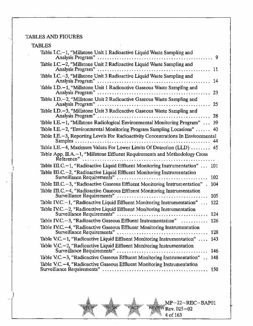
TABLES AND FIGURES
TABLESTable I.C. -1, "Millstone Unit 1 Radioactive Liquid Waste Sampling and
A nalysis Program " . .............................................. 9Table I.C.-2, "Millstone Unit 2 Radioactive Liquid Waste Sampling and
Analysis Program " ... ; .......................................... 11Table I.C.-3, "Millstone Unit 3 Radioactive Liquid Waste Sampling and
Analysis Program" .............................................. 14Table I.D.--1, "Millstone Unit 1 Radioactive Gaseous Waste Sampling and
Analysis Program" .............................................. 23Table I.D.-2, "Millstone Unit 2 Radioactive Gaseous Waste Sampling and
Analysis Program " .............................................. 25Table I.D.-3, "Millstone Unit 3 Radioactive Gaseous Waste Sampling and
Analysis Program " .............................................. 28Table I.E.-1, "Millstone Radiological Environmental Monitoring Program" ... 39Table I.E.-2, "Environmental Monitoring Program Sampling Locations" ...... 40Table I.E.-3, Reporting Levels For Radioactivity Concentrations In Environmental
Sam ples ....................................................... 44Table I.E.-4, Maximum Values For Lower Limits Of Detection (LLD) ........ 45Table App. II.A. -1, "Millstone Effluent Requirements and Methodology Cross
R eference" ......................................................Table III.C.-1, "Radioactive Liquid Effluent Monitoring Instrumentation" ... 101Table III.C.-2, "Radioactive Liquid Effluent Monitoring Instrumentation
Surveillance Requirements" ..................................... 102Table III.C.-3, "Radioactive Gaseous Effluent Monitoring Instrumentation" . 104Table III.C.-4, "Radioactive Gaseous Effluent Monitoring Instrumentation
Surveillance Requirements" ..................................... 105Table IVC.-1, "Radioactive Liquid Effluent Monitoring Instrumentation" ... 122Table IVC.-2, "Radioactive Liquid Effluent Monitoring Instrumentation
Surveillance Requirements" ..................................... 124Table IVC.-3, "Radioactive Gaseous Effluent Instrumentation" ........... 126Table IV.C.-4, "Radioactive Gaseous Effluent Monitoring Instrumentation
Surveillance Requirements" ..................................... 128Table V.C.- 1, "Radioactive Liquid Effluent Monitoring Instrumentation" .... 143Table V.C.-2, "Radioactive Liquid Effluent Monitoring Instrumentation
Surveillance Requirements" ..................................... 146Table V.C.-3, "Radioactive Gaseous Effluent Monitoring Instrumentation" .. 148Table VC.-4, "Radioactive Gaseous Effluent Monitoring InstrumentationSurveillance Requirements" ........................................... 150
,MP-22-REC-BAP01IMF . RW ev 025-02
4 of 163

FIGURESFigure I.C.- 1, "Reserved" ....................................... 20Figure I.C. -2, "Simplified Liquid Effluent Flow Diagram Millstone Unit 2 .... 21Figure I.C.-3, "Simplified Liquid Effluent Flow Diagram Millstone Unit 3 . . 22Figure I.D.-1, "Simplified Gaseous Effluent Flow Diagram Millstone
U nit O ne" .................................................... 34Figure I.D. -2, "Simplified Gaseous Effluent Flow Diagram Millstone
U nit Tw o" ..................................................... 35Figure I.D.-3, "Simplified Gaseous Effluent Flow Diagram Millstone
U nit Three" . ....... ........................................... 36Figure I.E.-1, "Inner Air Particulate And Vegetation Monitoring Stations" ... 42Figure I.E.-2, "Outer Terrestrial Monitoring Stations ...................... 43Figure III.D.-1, "Site Boundary for Liquid and Gaseous Effluents" . ........ 111Figure IVD.- 1, "Site Boundary for Liquid and Gaseous Effluents".......... 134Figure VD. -1, "Site Boundary for Liquid and Gaseous Effluents" .......... 157
& MP-22-REC-BAP01STOP .•EW•Rev. 025-02
S5 of 163

SECTION I.
Radiological Effluent Monitoring Manual(REMM)
For theMillstone Nuclear Power Station
Nos. 1, 2, & 3
Docket Nos. 50-245, 50-336, 50-423
.... A MP-22-REC-BAP01-. W Rev. 025-02
' 6 of 163
SECTION I. RADIOLOGICAL EFFLUENT MONITORING MANUAL (REMM)
I.A. Introduction
The purpose of Section I of this manual is to provide the sampling and analysisprograms which provide input to Section II for calculating liquid and gaseouseffluent concentrations and offsite doses. Guidelines are provided for operatingradioactive waste treatment systems in order that offsite doses are keptAs -Low -As - Reasonably- Achievable (ALARA).
The Radiological Environmental Monitoring Program outlined within thismanual provides confirmation that the measurable concentrations of radioactivematerial in the environment as a result of operations at the Millstone Site are nothigher than expected.
In addition, this manual outlines the information required to be submitted to theNRC in both the Annual Radiological Environmental Operating Report and theRadioactive Effluent Release Report.
MP-22--REC-REF03, "REMODCM Technical Information Document(TID)," has additional bases and technical information. It also contains a list ofexceptions to Regulatory Guide 1.21 (see Section 2 of the TID).
I.B. Responsibilities
All changes to the Radiological Effluent Monitoring Manual (REMM) shall bereviewed and approved by the Site Operations Review Committee prior toimplementation.
All changes and their rationale shall be documented in the Radioactive EffluentRelease Report.
It shall be the responsibility of the Site Vice President Millstone to ensure thatthis manual is used as required by the administrative controls of the TechnicalSpecifications. The delegation of implementation responsibilities is delineated inMP-22- REC-PRG, "Radiological Effluent Program."
I.C. Liquid Effluents
1. Liquid Effluent Sampling and Analysis Program
Radioactive liquid wastes shall be sampled and analyzed in accordance withthe program specified in Table I.C.-1 for Millstone Unit No. 1, Table I.C.-2for Millstone Unit No. 2, and Thble I.C.-3 for Millstone Unit No. 3. Theresults of the radioactive analyses shall be input to the methodology ofSection II to assure that the concentrations at the point of release are
.. MP-22-REC-BAP01T," ."T' H•• Rev. 025-02
7 of 163

maintained within the limits of Radiological Effluent Controls (SectionIII.D.1.a. for Millstone Unit No. 1, Section IVD.L.a. for Millstone Unit No.2, and Section VD.1.a. for Millstone Unit No. 3).
MP-22-REC-BAP01-A Rev. 025-02
- ?" J 8 of 163

Table I.C.- 1Millstone Unit 1 Radioactive Liquid Waste Sampling and Analysis Program
Liquid Release Sample Type and Minimum Analysis 'Type of Activity Lower LimitSource Frequency Frequency Analysis of Detection
(LLD)A( Ci/ml)
Any Batch Grab sample prior to Prior to each batch re- Principal Gamma 5x 10⁻⁷Release from any each batch releaseB lease Emitterssource Kr-85 i x 10-5
Prior to initial batch re- H-3 1 x 10⁻⁵lease from any onesource and monthlycomposite thereafterc
Grab sample prior to Prior to initial batch re- Gross alpha 1 x 10⁻⁷initial batch release lease from any onefrom any one source source and quarterly Sr-90 5 x 10⁻⁸and quarterly compos- thereafterite thereafter Fe-55 1 x 10⁻⁶
I
Table I.C.-iTABLE NOTATIONS
A. The LLD is the smallest concentration of radioactive material in a sample that will be detectedwith 95% probability with 5% probability of falsely concluding that a blank observationrepresents a "real" signal.
For a particular measurement system (which may include radiochemical separation):
4.66 Sb
(E)(V)(2.22x10 6)(ye-W')
Where:
• LLD is the lower limit of detection as defined above (as 1RCi per unit mass or volume)
• Sb is the standard deviation of the background counting rate or of the counting rate of a blanksample as appropriate (as counts per minute)
" E is the counting efficiency (as counts per transformation)
• V is the sample size (in units of mass or volume)
" 2.22 x 10⁶ is the number of transformations per minute per itCi
* Y is the fractional radiochemical yield (when applicable)
* I is the radioactive decay constant for the particular radionuclide
" At is the elapsed time between midpoint of sample collection and midpoint of counting time
3h, MP-22-REC-BAPO1e T, Rev. 025-02
9 of 163

It should be recognized that the LLD is defined as an a priori (before the fact) limit representingthe capability of a measurement system and not as an a posteriori (after the fact) limit for aparticular measurement.
Analyses shall be performed in such a manner that the stated LLDs Will be achieved underroutine conditions. Occasionally background fluctuations, unavoidably small sample sizes, thepresence of interfering nuclides, or other uncontrollable circumstances may render these LLDsunachievable. In such cases, the contributing factors will be identified and recorded on theanalysis sheet for the particular sample.
B. Prior to the sampling, each batch shall be isolated and at least two tank/sump volumes shall berecirculated or equivalent mixing provided.
C. A composite sample is one in which the quantity of liquid sampled is proportional to thequantity of liquid waste discharged and in which the method of sampling employed results in aspecimen which is representative of the liquids released. Prior to analysis, all samples takenfor the composite shall be thoroughly mixed in order for the composite sample to berepresentative of the effluents released.
S-T-" 'ARM AT J -MP-22-REC-BAP01
gRNERev. 025-02z 10 of 163

Table I.C.-2Millstone Unit 2 Radioactive Liquid Waste Sampling and Analysis Program
Liquid Release Sample Type and Minimum Analysis lype of Activity Lower LimitSource Frequency Frequency Analysis of Detection
(LLD)A_(4Ci/ml)
A.Batch ReleaseB'
1.Clean Waste Moni- Grab sample prior to Prior to each batch Principal Gamma 5 x 10⁻⁷
tor Tank, Aerated each batch release release EmittersC.Waste Monitor 1-131 1X 10⁻⁶Tank and SteamGenerator BulkD. Ce-144 5 x 10⁻⁶
Dissolved & 1 x 10⁻⁵Entrained GasesK.
2.Condensate Monthly H-3 1 x 10⁻⁵Polishing Facility CompositeF.,G.- Waste Quarterly Gross alpha I x 10-7SutmpE t CompositeEG. Sr -89, Sr-90 5 x 10⁻⁸
Fe-55 1 x 10⁻⁶
B.Continuous Release
1.Steam Generator Daily Grab Samplel'& Weekly Principal Gamma 5 x 10⁻⁷BlowdownH- prior to aligning to CompositeF.,G. EmittersC"
2.Service Water Long Island Sound for 1-131 1 x 10⁻⁶Effluent3 BC up_______ Ce- 144 5 x 10⁻⁶
3.Tirbine SumpsL. Monthly Grab Monthly Dissolved & 1 x 10⁻⁵Sample Entrained GasesK-
4.RBCCW SumpM" Weekly Grab or Com- Monthly H-3N' 1 x 10⁻⁵posite CompositeF.,G.
Weekly Composite Quarterly Gross alpha 1 x 10⁻⁷CompositeE'G. Sr-89, Sr-90 5 x 10⁻⁸
Fe-55 1 x 10⁻⁶
TABLE I.C.-2TABLE NOTATIONS
A. The LLD is the smallest concentration of radioactive material in a sample that will be detectedwith 95% probability with 5% probability of falsely concluding that a blank observationrepresents a "real" signal.
For a particular measurement system (which may include radiochemical separation):
4.66 SbLLD =
(E)(V)(2.22x10⁶)(ye -,W t)
MP-22-REC-BAI'O1STP T~l'K ACT RVE Rev. 025-0
11 of 163

Where:
• LLD is the lower limit of detection as defined above (as 1gCi per unit mass or volume)
0 Sb is the-standard deviation of the background counting rate or of the counting rate of a blanksample as appropriate (as counts per minute)
0 E is the counting efficiency (as counts per transformation)
• V is the sample size (in units of mass or volume)
• 2.22 x 10⁶ is the number of transformations per minute per [tCi
a Y is the fractional radiochemical yield (when applicable)
• ), is the radioactive decay constant for the particular radionuclide
0 At is the elapsed time between midpoint of sample collection and midpoint of counting time
It should be recognized that the LLD is defined as an a priori (before the fact) limit representingthe capability of a measurement system and not as an a posteriori (after the fact) limit for aparticular measurement.
Analyses shall be performed in such a manner that the stated LLDs will be achieved underroutine conditions. Occasionally background fluctuations, unavoidably small sample sizes, thepresence of interfering nuclides, or other uncontrollable circumstances may render these LLDsunachievable. In such cases, the contributing factors will be identified and recorded on theanalysis sheet for the particular sample.
B. A batch release is the discharge of liquid wastes of a discrete volume from the tanks listed inthis table. Prior to the sampling, each batch shall be isolated and at least two tank/sumpvolumes shall be recirculated or equivalent mixing provided. If the steam generator bulk cannot be recirculated prior to batch discharge, samples will be obtained by representativecompositing during discharge.
C. The LLD will be 5 x 10⁻⁷ [tCi/ml. The principal gamma emitters for which this LLD applies areexclusively the following radionuclides: Mn-54, Fe-59, Co-58, Co-60, Zn-65, Mo-99,Cs-134, Cs-137, and Ce-141. Ce-144 shall also be measured, but with an LLD of 5 x 10⁻⁶ILCi/ml. This list does not mean that only these nuclides are to be detected and reported.Other peaks which are measurable and identifiable, together with the above nuclides, shall alsobe identified and reported. Nuclides which are below the LLD for the analyses should not bereported as being present at the LLD level. When unusual circumstances result in a priori LLDshigher than required, the reasons shall be documented in the Radioactive Effluent ReleaseReport.
D. For the Steam Generator Bulk:LF the applicable batch gamma activity is not greater than 5 x 10- 7 giCi/ml, THEN the samplingand analysis schedule for gross alpha, Sr-89, Sr-90, Fe-55 are not required.
TH.IN. -- .. .MP-22-REC-BAP01S'T" -A RgF/IEW Rev. 025-02
12 of 163

E. For the Condensate Polishing Facility (CPF) waste neutralization sump:IF there is no detectable tritium in the steam generators, THEN tritium sampling and analysesis not required.IF the gross gamma activity in the grab sample taken prior to release does not exceed5 x 10-7 ICi/ml, THEN the sampling and analysis schedule for gross alpha, Sr-89, Sr-90 andFe-55 are not required.
F. For Batch Releases and Steam Generator Blowdown only, a composite sample is one in whichthe quantity of liquid sampled is proportional to the quantity of liquid waste discharged and inwhich the method of sampling employed results in a specimen which is representative of theliquids released.
G. Prior to analysis, all samples taken for the composite shall be thoroughly mixed in order for thecomposite sample to be representative of the effluents released.
H. For the Steam Generator Blowdown:IF the steam generator gross gamma activity does not exceed 5 x 10⁻⁷ Ci/ml, THEN thesampling and analysis schedule for all principal gamma, 1-131, Ce-144, noble gases, grossalpha, Sr-89, Sr-90 and Fe-55 are not required.
I. Daily grab samples shall be taken at least five days per week. For service water, daily grabsshall include each train that is in-service.
J. For the Service Water:IF a weekly gamma analysis does not indicate a gamma activity greater than 5 xl 0-7 tiCi/mI,THEN the sampling and analysis schedule for gross alpha, Sr-89, Sr-90, Fe-55 are notrequired.
K. LLD applies exclusively to the following radionuclides: Kr-87, Kr-88, Xe-133, Xe-133m,Xe-135, and Xe-138. This list does not mean that only these nuclides are to be detected andreported. Other peaks which are measurable and identifiable, together with the abovenuclides, shall also be identified and reported. Nuclides which are below the LLD for theanalyses should not be reported as being present at the LLD level. When unusualcircumstances result in a priori LLDs higher than required, the reasons shall be documented inthe "Radioactive Effluent Release Report."
L. For the Turbine Building Sump:IF there is no detectable tritium in the steam generators, THEN tritium sampling and analysesis not required.IF the steam generator gross gamma activity does not exceed 5 X 10⁻⁷ p.Ci/ml, OR sump isdirected to radwaste treatment, THEN the sampling and analysis schedule for all principalgamma, 1-131, Ce-144, noble gases, gross alpha, Sr-89, Sr-90 and Fe-55 are notrequired.IF the release pathway is directed to yard drains, THEN the LLD for 1-131 shall be 1.5 x 10⁻⁷
ViCi/mI and for gross alpha 1 x 10⁻⁸ i, Ci/ml.
M. For the RBCCW Sump:IF the RBCCW Sump is directed to radwaste treatment or is not aligned to Long Island Sound,THEN sampling is not required.IF the applicable batch gamma activity is not greater than 5 x 10⁻⁷ RCi/ml, THEN samplingand analysis schedule for gross alpha, Sr-89, Sr-90, Fe-55 are not required.
N. Detectable tritium shall be used to estimate tritium releases to the atmosphere via theblowdown tank vent.
.- OP .- MP-22-REC-BAP01-K" 1T0'7t EW Rev. 025- 02
13 of 163

Table I.C.-3Millstone Unit 3 Radioactive Liquid Waste Sampling and Analysis Program
Liquid Release Sample Type and Minimum Analysis Type of Activity Lower LimitSource Frequency Frequency Analysis of Detection(LLD)A
($iCi/ml)
A.Batch ReleaseB.
1.Condensate Polish- Grab sample prior Prior to each batch Principal Gamma 5 x 10⁻⁷ing Facility Waste to each batch release' release Emittersc"
NeutralizationSumpE. 1-131 1 x 10⁻⁶
Ce-144 5 x 10⁻⁶
Dissolved & I x 10-5Entrained Gases-
2.Waste Test Tanks, Monthly H-3 1 x 10⁻⁵Low Level Waste CompositeFG.Tank, Boron TestTanks and Steam Quarterly Gross alpha 1 x 10⁻⁷Generator Bulk D. CompositeF"G. Sr-89, Sr-90 5 x 10⁻⁸
Fe-55 1 x 10⁻⁶
B.Continuous Release
1.Steam Generator Daily Grab Sample'" Weekly Principal Gamma 5 x 10⁻⁷BlowdownH" Compositer.,G. Emittersc
2.Service Water Ef- 1-131 1 x 10⁻⁶fluentJ.
Ce-144 5 x 10⁻⁶
3.Thrbine Building Monthly Grab Monthly Dissolved & 1 x 10⁻⁵SumpsL Sample Entrained GasesK-
Weekly Grab or Com- Monthly H-3M. 1 x 10⁻⁵posite CompositeF.,G.
Weekly Composite Quarterly Gross alpha 1 x 10⁻⁷CompositeR.G. Sr--89, Sr-90 5 x 10⁻⁸
Fe-55 1 x 10⁻⁶
TABLE I.C.-3TABLE NOTATIONS
A. The LLD is the smallest concentration of radioactive material in a sample that will be detectedwith 95% probability with 5% probability of falsely concluding that a blank observationrepresents a "real" signal.
INA. A...--...... MP-22-REC-BAP01... W..- ACT R~V Rev. 02~~~Rev. 025-02
14 of 163

For a particular measurement system (which may include radiochemical separation):
LD4.66 Sb
(E)(V)(2.22x10 6)(Ye -,D)
Where:
• LLD is the lower limit of detection as defined above (as [tCi per unit mass or volume)
• Sb is the standard deviation of the background counting rate or of the counting rate of a blanksample as appropriate (as counts per minute)
• E is the counting efficiency (as counts per transformation)
• V is the sample size (in units of mass or volume)
• 2.22 x 10⁶ is the number of transformations per minute per p.Ci
• Y is the fractional radiochemical yield (when applicable)
* 1 is the radioactive decay constant for the particular radionuclide
* At is the elapsed time between midpoint of sample collection and midpoint of counting time
It should be recognized that the LLD is defined as an a priori (before the fact) limit representingthe capability of a measurement system and not as an a posteriori (after the fact) limit for aparticular measurement.
Analyses shall be performed in such a manner that the stated LLDs will be achieved underroutine conditions. Occasionally background fluctuations, unavoidably small sample sizes, thepresence of interfering nuclides, or other uncontrollable circumstances may render these LLDsunachievable. In such cases, the contributing factors will be identified and recorded on theanalysis sheet for the particular sample.
B. A batch release is the discharge of liquid wastes of a discrete volume from the tanks listed inthis table. Prior to the sampling, each batch shall be isolated and at least two tank/sumpvolumes shall be recirculated or equivalent mixing provided. If the steam generator bulk cannot be recirculated prior to batch discharge, samples will be obtained by representativecompositing during discharge.
C. The LLD will be 5 x 10⁻⁷ RCi/ml. The principal gamma emitters for which this LLD applies areexclusively the following radionuclides: Mn-54, Fe-59, Co-58, Co-60, Zn-65, Mo-99,Cs-134, Cs-137, and Ce-141. Ce-144 shall also be measured, but with an LLD of 5 x 10⁻⁶LCi/ml. This list does not mean that only these nuclides are to be detected and reported.Other peaks which are measurable and identifiable, together with the above nuclides, shall alsobe identified and reported. Nuclides which are below the LLD for the analyses should not bereported as being present at the LLD level. When unusual circumstances result in a priori LLDshigher than required, the reasons shall be documented in the Radioactive Effluent ReleaseReport.
D. For the Steam Generator Bulk:IF the applicable batch gamma activity is not greater than 5 x 10⁻⁷ [0Ci/ml, THEN the samplingand analysis schedule for gross alpha, Sr-89, Sr-90, Fe-55 are not required.
,-MP-22-REC-BAPO1
'ThI•-.,''-; ' - " Rev. 025-02
. 15 of 163

E. For the Condensate Polishing Facility (CPF) waste neutralization sump:IF there is no detectable tritium in the steam generators, THEN tritium sampling and analysesis not required.IF the gross gamma activity in the grab sample taken prior to release do.es not exceed5 x 10-7 [0Ci/ml, THEN the sampling and analysis schedule for gross alpha, Sr-89, Sr-90 andFe-55 are not required.
F. For Batch Releases and Steam Generator Blowdown only, a composite sample is one in whichthe quantity of liquid sampled is proportional to the quantity of liquid waste discharged and inwhich the method of sampling employed results in a specimen which is representative of theliquids released.
G. Prior to analysis, all samples taken for the composite shall be thoroughly mixed in order for thecomposite sample to be representative of the effluents released.
H. For the Steam Generator Blowdown:IF the steam generator gross gamma activity does not exceed 5 x 10⁻⁷ 0Ci/ml, THEN thesampling and analysis schedule for all principal gamma, [-131, Ce-144, noble gases, grossalpha, Sr-89, Sr-90 and Fe-55 are not required.
Steam Generator Blowdown samples are not required when blowdown is being recovered.
I. Daily grab samples. shall be taken at least five days per week. For service water, daily grabsshall include each train that is in-service.
J. For the Service Water:IF a weekly gamma analysis does not indicate a gamma activity greater than 5 x1 0-7 ILCi/ml,THEN the sampling and analysis schedule for gross alpha, Sr-89, Sr-90, Fe-55 are notrequired.
K. LLD applies exclusively to the following radionuclides: Kr-87, Kr-88, Xe- 133, Xe- 133m,Xe-135, and Xe-138. This list does not mean that only these nuclides are to be detected andreported. Other peaks which are measurable and identifiable, together with the abovenuclides, shall also be identified and reported. Nuclides which are below the LLD for theanalyses should not be reported as being present at the LLD level. When unusualcircumstances result in a priori LLDs higher than required, the reasons shall be documented inthe "Radioactive Effluent Release Report."
L. For the Turbine Building Sump:IF there is no detectable tritium in the steam generators, THEN tritium sampling and analysesis not required.IF the steam generator gross gamma activity does not exceed 5 x 10⁻⁷ O0Ci/ml, OR sump isdirected to radwaste treatment, THEN the sampling and analysis schedule for all principalgamma, 1-131, Ce-144, noble gases, gross alpha, Sr-89, Sr-90 and Fe-55 are notrequired.IF the release pathway is directed to yard drains, THEN the LLD for 1-131 shall be 1.5 x 10⁻⁷j.Ci/ml and for gross alpha 1 x 10⁻⁸ ILCi/ml.
M. Detectable tritium shall be used to estimate tritium releases to the atmosphere via theblowdown tank vent.
, T'K. • -- ':. MP-22-REC-BAPO1
T. .... Rev. 025-02
16 of 163

2. Liquid Radioactive Waste Treatment
a. Dose Criteria for Equipment Operability Applicable to All MillstoneUnits
The following dose criteria shall be applied separately to each Millstoneunit.
1) IF the radioactivity concentration criteria for the Unit 3 steamgenerator blowdown is exceeded with blowdown recovery notavailable to maintain releases to as low as reasonably achievable; or,IF any of the other radioactive waste processing equipment listed inSection b. are not routinely operating, THEN doses due to liquideffluents from the applicable waste stream to unrestricted areas shallbe projected at least once per 31 days in accordance with themethodology and parameters in Section II.C.5.
2) IF any of these dose projections exceeds 0.006 mrem to the totalbody or 0.02 mrem to any organ, THEN best efforts shall be made toreturn the processing equipment to service, or to limit discharges viathe applicable waste stream.
3) IF an actual dose due to liquid effluents exceeds 0.06 mrem to thetotal body or 0.2 mrem to any organ AND the dose from the wastestream with processing equipment not operating exceeds 10% of oneof these limits, THEN prepare and submit to the Commission aSpecial Report within 30 days as specified in Section 2.c.
b. Required Equipment for Each Millstone Unit
Best efforts shall be made to return the applicable liquid radioactivewaste treatment system equipment specified below for each unit toservice or to limit discharge via the applicable waste stream if theprojected doses exceed any of the doses specified above.
., ._... .. - .MP-22-REC-BAP01.3. T-" INi w Rev. 025-02
- 17 of 163

1. Millstone Unit No. 1
Waste Stream Processing Equipment
Reactor cavity water One filter and one demineralizer
2. Millstone Unit No. 2
Waste Stream Processing Equipment
Clean liquid Deborating ion exchanger (T11) ORPurification ion exchanger (T10A or T10B) OREquivalent ion exchangerPrimary demineralizer (J22 A or B) OREquivalent demineralizer
Secondary demineralizer (T23 A or B) OREquivalent demineralizer//Aerated liquid
Aerated liquid Demineralizer (124) OR Equivalent demineralizer
3. Millstone Unit No. 3
Waste Stream Processing Equipment or Radioactivity Concentration
High level Demineralizer filter (LWS-FLT3) and Demineralizer (LWS-DEMN2) ORDemineralizer (LWS-DEMN1) and Demineralizer filter (LWS-FLT1)
Boron recovery Cesium ion exchanger (DEMN A or B)
Boron evaporator (EV- 1)
Low level High level processing equipment
Steam generator Blowdown recovery when total gamma activity exceeds 5E-7 [CCi/mlblowdown or tritium activity exceeds 0.02 ItCi/ml.
c. Report Requirement For All Three Millstone Units
If required by Section 2.a.3), prepare and submit to the Commission aSpecial Report within 30 days with the following content:
° Explanation of why liquid radwaste was being discharged withouttreatment, identification of any equipment not in service, and thereason for the equipment being out of service,
a Action(s) taken to restore the equipment to service, and
* Summary description of action(s) taken to prevent a recurrence.
STOJ~ THINK...4AMP-22-REC-BAP01
'"M Rev. 025-02, 18 of 163
3. Basis for Liquid Sampling, Analysis and Radioactive Treatment System Use
Paragraph (a)(2) of Part 50.36a provides that licensee will submit an annualreport to the Commission which specifies the quantity of each of theprincipal radionuclides released to unrestricted areas in liquid effluentsduring the past 12 months of plant operation. The indicated liquidsurveillance programs (as directed by surveillance requirements forRadiological Effluent Controls in Sections III.D.l.a., IVD.1.a., and VD.1.a.provides the means to quantify and report on liquid discharges from releasepathways. As specified in Regulatory Guide 1.21, this program monitors allmajor and potentially significant paths for release of radioactive material inliquid effluents during normal reactor operations, including anticipatedoperational occurrences. There are many minor release pathways which arenot routinely monitored. The Millstone Effluent Control Program includes,as needed, evaluations to determine if any release point should be added tothe REMODCM surveillance program. This information also provides forthe assessment of effluent concentrations and environmental dose impactsfor the purpose of demonstration compliance with the effluent limits of10 CFR 20, and dose objectives of 10 CFR 50, Appendix I. The requireddetection capabilities for radioactive materials in liquid waste samples aretabulated in terms of Lower Limits of Detection (LLDs) and are selectedsuch that the detection of radioactivity in effluent releases will occur at levelsbelow which effluent concentration limits and off-site dose objectives wouldbe exceeded. The LLDs are listed in Table 4.11-1 of NUREG- 1301 exceptfor the LLD for Ce-144 which is contained in Footnote (3) of Table 4.11-1of NUREG-1301.
The indicated liquid radwaste treatment equipment for each Unit have beendetermined, using the GALE code, to be capable to minimize radioactiveliquid effluents such that the dose objectives of Appendix I can be met forexpected routine (and anticipated operational occurrence) effluent releases.This equipment is maintained and routinely operated to treat appropriateliquid waste streams without regards to projected environmental doses.
If not already in use, the requirement that the appropriate portions of theliquid radioactive waste treatment system for each Unit be returned toservice when the specified effluent doses are exceeded provides assurancethat the release of radioactive materials in liquid effluents will be kept "aslow as is reasonably achievable." This condition of equipment usageimplements the requirements of 10 CFR 50.36a, General Design Criterion 60of Appendix A to 10 CFR 50, and the design objective given in Section II.D.of Appendix I to 10 CFR 50. The specified dose limits governing therequired use of appropriate portions of the liquid radwaste treatment systemwere selected as a suitable fraction of the dose design objectives set forth inSection II.A. of Appendix 1, 10 CFR 50 for liquid effluents following theguidance given in NUREG- 1301.
- .. MP-22-REC-BAP01A0T Rev. 025-02
'T' - 19 of 163

Figure I.C.- 1, "Reserved
ST.o ... i.. K" MP-22-REC-BAP01
AT'- R•,•W Rev. 025-02
20 of 163

Figure I.C.-2, "Simplified Liquid Effluent Flow Diagram Millstone Unit 2"
*Tutblnc Bldg floor drains nnomally to sturm drains.Drains may be diverted to ihe radwasic trcatment system.
=I Component included is radwasic treatmentequipment requirement
INK71T~
MP-22-REC-BAP016zW Rev. 025-02
21lof 163

Figure I.C.-3, "Simplified Liquid Effluent Flow Diagram Millstone Unit 3"
St:xm Ccnentor Blowdown (Of=a Cyd~c)
Co&pacnci included In= mdwasteic tumem ouipjcnEnncquirmmax
- Tf1NK ACT7*;,MP-22-REC-BAP01R Rev. 025- 02
22 of 163

I.D. Gaseous Effluents
1. Gaseous Effluent Sampling and Analysis Program
Radioactive gaseous wastes shall be sampled and analyzed in accordancewith the program specified in Table I.D.- 1 for Millstone Unit No. 1, TableI.D.-2 for Millstone Unit No. 2, and Table I.D.-3 for Millstone Unit No. 3.The results of the radioactive analyses shall be input to the methodology ofSection II to assure that offsite dose rates are maintained within the limits ofRadiological Effluent Controls (Section III.D.2.a. for Millstone Unit No. 1,Section IVD.2.a. for Millstone Unit No. 2, and Section V.D.2.a. for MillstoneUnit No. 3).
Table I.D.- 1Millstone Unit 1 Radioactive Gaseous Waste Sampling and Analysis Program
Gaseous Release Sample Type and Minimum TIype of Activity Lower LimitPoint or Source Frequency Analysis Analysis of Detection
Frequency (LLD)A(giCi/ml)
A.Spent Fuel Pool Monthlyu - Gaseous Monthly Kr-85 1 x 10⁻⁴Island Vent Grab Sample H-3 1 x 10⁻⁶
ContinuousB-,E T'wice per month Principal Particulate 1 x 10-11Particulate Sample Gamma EmittersC" -
(with half lives greaterthan 8 days)
ContinuousB.,E. Quarterly Sr-90, Gross alpha 1 x 10-11Particulate Sample Composite
ContinuousB.,E. Continuous Kr-85 I x 10-6Noble Gas Monitor
B.Balance of Continuous1',E. TUvice per month Principal Particulate I x 10-11Plant Vent Particulate Sample Gamma Emittersc. -
(with half lives greaterthan 8 days)
Twice per month- Sr-90, Gross alpha 1 x 10-11
Grab sample of Reactor Prior to processing H-3 1 x 10⁻⁵Bldg evaporator staging of each batchtank prior to processing
Table I.D.-ITABLE NOTATIONS
A. The lower limit of detection (LLD) is defined in Table Notations, Item a, of Tables I.C.-1, I.C.-2,or I.C.-3.
B. The ratio of the sample flow rate to the sampled stream flow rate shall be known.
A&4REI- MP-22-REC-BAP01
0WRev.25-02,• 23 of 163

C. For particulate samples, the LLD will be 1 x 10-11 IVCi/cc. The principal gamma emitters forwhich this LLD applies are exclusively the following radionuclides: Mn-54, Co-60, Zn-65,Cs-134, Cs-137, and Ce-144. The list does not mean that only these nuclides are to bedetected and reported. Other peaks which are measurable and identifiable, together with theabove nuclides, shall also be identified and reported. Nuclides which are below the LLD for theanalyses should not be reported as being present at the LLD level for that nuclide. Whenunusual circumstances result in a priori LLDs higher than required, the reasons shall bedocumented in the Radioactive Effluent Release Report.
D. IF there is an unexplained increase of the SFPI Vent noble gas monitor of greater than a factorof ten, OR the monitor reads 8.8E-5 [tCi/cc or greater, THEN sampling and analysis shall alsobe performed within 24 hours.
E. Continuous when exhaust fans are in operation.
...... -MP-22-REC-BAP01
'T, -- V!Rev.025 -0224 of 163

Table I.D.- 2Millstone Unit 2 Radioactive Gaseous Waste Sampling and Analysis Program
Gaseous Sample Type and Minimum Wype of Activity Lower LimitRelease Point Frequency Analysis Analysis of Detection
or Source Frequency (LLD)A (JCi/mi)
A.Batch Release Principal Particulate 1 x 10-
1.Waste Gas Stor- Gaseous Grab Prior to each Each Tank Discharge Gamma EmittersBage TankH Waste Gas Tank Discharge H-3 1 x 10-b
B.Containment&Aux Building Releases1.Containment Gaseous Grab of purges 1. Prior to purge Principal Gamma 1 x 10⁻⁴
Purge and vents 2. Weekly for venting EmittersB2.Containment 1. Prior to Each PurgeJ & prior to venting-
Venting 2. Every two weeks for samples taken due toVentingi Footnote I-
3.Open Equip- Monthly H-3 1 x 10⁻⁶ment HatchDuring Outages
4.Spent Fuel Pool Continuous Particulate for Weekly Particulate Gamma NAOpen Equipment Hatch emitters for 1/2 hrduring Outage count (I-131, others
with half-life great-er than 8 days)
Continuous Charcoal for Weekly 1-131 and 1-133 for NAOpen Equipment Hatch one hour countduring Outaqe & Aux BldgRollup Door,
Gaseous Grab at Equip- Daily Noble Gases - 1 x 10⁻⁴
ment Hatch & Aux Bldg Gross ActivityRollup DoorL
C.Continuous Release1.Vent Monthly - Gaseous Grab Monthly2 '- Principal Gamma 1 x 10⁻⁴
(RM8132B) SampleC.,K. EmittersB
H-P3 1 x 10-62.Millstone Continuous Charcoal Sam- Weekly 1-131 1 x 10-12
Stack pleD'"E 1-133 1 x 10⁻¹⁰(RM8169-1) Continuous Particulate Weekly Principal Particu- I x IF =
SampleD.'E late Gamma Emit-tersB - (I-131, oth-ers with half livesgreater than 8 days)
Continuous Particulate Quarterly Composite Sr-89, Sr-90 - 1 x 10-11SampleD. Gross alpha 1 x 10-11Continuous Noble Gasp- Continuous Monitor Noble Gases - 1 x 10⁻⁶
_ Gross Activity
TABLE I.D.-2TABLE NOTATIONS
A. The lower limit of detection (LLD) is defined in Table Notations, Item a, of Tables I.C.-1, I.C.-2,or I.C.-3.
STc~P'
w , MP-22-REC-BAPO1
THI:NK AGT REYUW Rev. 025-02
25 of 163

B. For gaseous samples, the LLD will be 1 x 10⁻⁴ tCi/cc and for particulate samples, the LLD willbe 1 x 10-11 0Ci/cc. The principal gamma emitters for which these LLDs apply are exclusivelythe following radionuclides: Kr-87, Kr-88, Xe-133, Xe-133m, Xe-135, and Xe-138 forgaseous emission and Mn-54, Fe-59, Co-58, Co-60, Zn-65, Mo-99, 1-131, Cs-134,Cs- 137, Ce- 141, and Ce- 144 for particulate emissions. The list does not mean that onlythese nuclides are to be detected and reported. Other peaks which are measurable andidentifiable, together with the above nuclides, shall also be identified and reported. Nuclideswhich are below the LLD for the analyses should not be reported as being present at the LLDlevel for that nuclide. When unusual circumstances result in a priori LLDs higher than required,the reasons shall be documented in the "Radioactive Effluent Release Report."
C. Sampling and analysis shall also be performed 24 to 72 hours after:
(1) reactor shutdown or startup, or
(2) reactor power change greater than 15% of maximum power within a one hour period. Ifpower change is part of a series of step changes, the sample may be collected 24 to 72hours after last power change step.
D. The ratio of the sample flow rate to the sampled stream flow rate shall be known.
E. RESERVED
F. Samples shall be changed at least once per seven days and analyses shall be completedwithin 48 hours after changing.
For Unit 2 vent only
Sampling shall also be performed at least once per 24 hours for at least 7 days following eachshutdown, startup, or thermal power change exceeding 15% of rated thermal power within a1 -hour period and analyses shall be completed within 48 hours of changing. When samplescollected for 24 hours are analyzed, the corresponding LLDs may be increased by a factor of10. This requirement does not apply if: (1) analysis shows that the Dose Equivalent 1-131concentration in the reactor coolant has not increased more than a factor of three; and (2) thenoble gas monitor shows that effluent activity has not increased more than a factor of three.
G. IF the refueling cavity is flooded and there is fuel in the cavity, THEN grab samples for tritiumshall be taken weekly. The grab sample shall be taken from the Millstone Stack or vent wherethe containment ventilation is being discharged at the time of sampling.
H. Waste Gas Storage Tanks are normally released on a batch basis via the Millstone Stack.However, for the purpose of tank maintenance, inspection, or reduction of oxygenconcentration, a waste gas tank may be vented or purged with nitrogen and released to theenvironment via the normal or alternate pathway using one of the following methods:
Method A: Without a permit provided the following conditions are met:
(1) The previous batch of radioactive waste gas has been discharged to a final tank pressureof less than 5 PSIG.
(2) No radioactive gases have been added to the gaseous processing system since the (previous discharge.
_ ..... ,-- -!MP-22-REC-BAP01N• _ ,-. Rev. 025-02
26 of 163

(3) Valve lineups are verified to ensure that no radioactive waste gases will be added to thetank.
(4) Prior to initiation of the vent or purge, a sample of the gas in the tank will be taken andanalyzed for any residual gamma emitters and tritium. The tank may be released if:
a) Tank activity is less than 1% of the activity released in the previous batch release fromthe tank, or less than 1% of the activity released to date for the calendar year, and
b) the activity of Kr-85 and Xe-133 is less than 0.01 Ci and the activity of all other gasesis less than 0.001 Ci.
Method B: With a permit provided valve lineups are verified to ensure that no radioactive wastegases will be added to the tank.
I. IF, compared to the radioactivity at the time of the air sample, a Radiation Monitor RM8123 orRM8262 gas channel or a particulate channel increases by a factor of two, THEN a newcontainment air sample shall be taken.IF, containment noble gas activity exceeds 1 E-6 [tCi/cc as indicated by the last grab sample,THEN sampling frequency shall be increased to weekly until such time that the activity is lessthan 1E-6 pCi/cc.
J. During an outage a sample is only required prior to the initial purge.
K. IF there is an increase of the Millstone Stack or Unit 2 Vent noble gas monitor of greater than50%, THEN sampling and analysis shall also be performed within 24 hours, except for thefollowing conditions:
(1) the increase is already accounted for, or
(2) the monitor has returned to within 20% of the average reading prior to the increase.
IF the Millstone Stack or Unit 2 Vent noble gas monitor increased greater than 50% for morethan one hour and has decreased prior to collecting a sample representative of the elevatedreading, THEN an estimate of radioactivity released during the period of elevated reading shallbe made.
L. Continuous charcoal sample at Aux Bldg Rollup Door and daily gas sample at EquipmentHatch and Aux Bldg Rollup Door are only required when moving fuel. Sampling at theEquipment Hatch is not required if the Enclosure Building is intact. Sampling at the Aux BldgRollup Door is not required if the rollup door is closed.
, ,TH-I" "' MP-22-REC-BAPO1, T I0, "A .- 02&"-• -4.
S- : : '" -... ..-. Rev. 0257027 of 163

Table I.D.-3Millstone Unit 3 Radioactive Gaseous Waste Sampling and Analysis Program I C2
Gaseous Sample lype and Minimum 'ype of Activity Lower LimitRelease Point Frequency Analysis Analysis of Detection
or Source Frequency (LLD)A- (oCi/ml)
A. Containment and Fuel Building Release1.Containment Gaseous, particulate and Prior to each purge or Principal gamma 1 x 10⁻⁴
Hogger Draw- charcoal grab prior to drawdown; weekly for emittersB.down each drawdown venting & prior to
2.Containment venting samples takenPurge due to Footnote I.
3.Containment Gaseous grab prior to Prior To Each Draw- 1-131 1 x 10-12Vent each purgeH. down 1-133 1 x 10⁻¹⁰
Gaseous Grab every two Principal particulate 1 x 10-114.Open Equip. weeks for ventingi' gamma emittersB. -
Hatch During (1-131, others with half livesOutages greater than 8 days)
5.Fuel Building Monthly for all re- H-3 1 x 10⁻⁶lease sources exceptEquipment Hatch
Continuous particulate Weekly Particulate gamma emit- NAat open equipment hatch ters for 1/2 hour count
(1-131, others with half-lifegreater than 8 days)
Continuous charcoal at Weekly 1- 131 and 1- 133 for one NAequipment hatch and hour countfuel building rollupdoorsK.Gaseous grab at equip- Daily Noble Gases - Gross 1 x 10⁻⁴ment hatch & fuel build- Activitying rollup doorsK'
B.Continuous Release1.Unit 3 Ventila- Monthly - Gaseous MonthlyC-,J" Principal particulate 1 X 10⁻⁴
tion Vent Grab SampleC-.j gamma emittersB(HVR-RE10B) H-3 1 X 10⁻⁶
2.Engineered Continuous charcoal Weekly 1-131 1 x 10-12Safeguards sampleD,"E 1-133 1 x 10⁻¹⁰Building Continuous particulate Weekly Principal particulate 1 x 10-11(HVQ-RE49) sampleD.,F, gamma emittersB. -
3.Millstone (1-131, others with half livesStack via greater than 8 days)
SLCRS Continuous particulate Quarterly composite Sr-89, Sr-90 1 x 10-11(HVR- sampleD. Gross alpha I x 10-11RE19B) Continuous noble gasp" Continuous Noble gases - gross 1 X 10⁻⁶
monitor activity
TABLE I.D.-3TABLE NOTATIONS
A. The lower limit of detection (LLD) is defined in Table Notations, Item a, of Tables I.C.-1, I.C.-2,or I.C.-3.
7 INK" AC1~MP-22-REC-BAP01
R'R8W ev. 025-02
28 of 163

B. For gaseous samples, the LLD will be 1 x 10⁻⁴ [Ci/cc and for particulate samples, the LLD willbe 1 x 10-11 [Ci/cc. The principal gamma emitters for which these LLDs apply are exclusivelythe following radionuclides: Kr-87, Kr-88, Xe-133, Xe-133m, Xe-135, and Xe-138 forgaseous emission and Mn-54, Fe-59, Co-58, Co-60, Zn-65, Mo-99, 1-131, Cs-134,Cs-137, Ce-141, and Ce-144 for particulate emissions. The list does not mean that onlythese nuclides are to be detected and reported. Other peaks which are measurable andidentifiable, together with the above nuclides, shall also be identified and reported. Nuclideswhich are below the LLD for the analyses should not be reported as being present at the LLDlevel for that nuclide. When unusual circumstances result in a priori LLDs higher than required,the reasons shall be documented in the Radioactive Effluent Release Report.
C. For the ventilation vent and SLCRS, sampling and analysis shall also be performed 24 to 72hours after:
(1) reactor shutdown or startup, or
(2) reactor power change greater than 15% of maximum power within a one hour period. Ifpower change is part of a series of step changes, the sample may be collected 24 to 72hours after the last power change step.
D. The ratio of the sample flow rate to the sampled stream flow rate shall be known.
E. RESERVED
F. Samples shall be changed at least once per seven days and analyses shall be completedwithin 48 hours after changing.
For Unit 3 Vent only:
Sampling shall also be performed at least once per 24 hours for at least 7 days following eachshutdown, startup, or thermal power change exceeding 15% of rated thermal power within a1 -hour period and analyses shall be completed within 48 hours of changing. When samplescollected for 24 hours are analyzed, the corresponding LLDs may be increased by a factor of10. This requirement does not apply if: (1) analysis shows that the Dose Equivalent 1-131concentration in the reactor coolant has not increased more than a factor of three; and (2) thenoble gas monitor shows that effluent activity has not increased more than a factor of three.
G. IF the refueling cavity is flooded and there is fuel in the cavity, THEN grab samples for tritium
shall be taken weekly from the ventilation vent.
H. During an outage a sample is only required prior to the initial purge.
I. I. compared to the radioactivity at the time of the air sample, Radiation Monitor CMS22 gaschannel or particulate channel increases by a factor of two, THEN a new containment airsample shall be taken.
IF, containment noble gas activity exceeds 1 E-6 0Ci/cc as indicated by the last grab sample,THEN sampling frequency shall be increased to weekly until such time that the activity is lessthan 1E-6 0Ci/cc.
-'R/ Rev 025 -02
'T 29 of 163

J. IF there is an unexplained increase of the Unit 3 ventilation vent or SLCRS noble gas monitorof greater than 50%, THEN appropriate sampling and analysis shall also be performed within24 hours, except for the following conditions:
(1) the increase is already accounted for, or
(2) the monitor has returned to within 20% of the reading prior to the increase.
IF the SLCRS or Unit 3 Vent noble gas monitor increased greater than 50% for more than onehour and has decreased prior to collecting a sample representative of the elevated reading,THEN an estimate of radioactivity released during the period of elevated reading shall bemade.
K. Continuous charcoal sample at any open Fuel Bldg Rollup Door and daily gas sample atEquipment Hatch and at any open Fuel Bldg Rollup Door are only required when moving fuel.Sampling at a Fuel Bldg Rollup Door is not required if the rollup door is closed.
STOP T~fNK' AOT~,MP-22-REC-BAP01
R•-•NRev. 025-02
30 of 163

2. Gaseous Radioactive Waste Treatment
a. Dose Criteria for Equipment Operability Applicable to All MillstoneUnits
The following dose criteria shall be applied separately to each Millstoneunit.
1) IF any of the radioactive waste processing equipment listed inSection 2.b. are not routinely operating, THEN doses due to gaseouseffluents from the untreated waste stream to unrestricted areas shallbe projected at least once per 31 days in accordance with themethodology and parameters in Section II.D.4. For each wastestream, only those doses specified in Section II.D.4. need to bedetermined for compliance with this section.
2) IF any of these dose projections exceed 0.02 mrad for gammaradiation, 0.04 mrad for beta radiation or 0.03 mrem to any organdue to gaseous effluents, THEN best efforts shall be made to returnthe processing equipment to service.
3) IF actual doses exceed 0.2 mrad for gamma radiation, 0.4 mrad forbeta radiation or 0.3 mrem to any organ AND the dose from a wastestream with equipment not operating exceed 10% any of theselimits, THEN prepare and submit to the Commission a report asspecified in Section I.D.2.c.
b. Required Equipment for Each Millstone Unit
Best efforts shall be made to return the gaseous radioactive wastetreatment system equipment specified below for each unit to service ifthe projected doses exceed any of doses specified above. For the Unit 2gas decay tanks, the tanks shall be operated to allow enough decay timeof radioactive gases to ensure that the Radiological Effluent Controldose limits are not exceeded.
R, , MP-22-REC-BAPO1........... ',,W F W Rev. 025-02
__ • 31 of 163

1. Millstone Unit No. 1
Waste Stream Processing Equipment
None Specified JNone required
2. Millstone Unit No. 2
Waste Stream Processing Equipment
Gaseous Radwaste Five (5) gas decay tanksTreatment System
One waste gas compressor
Ventilation Exhaust Auxiliary building ventilation HEPA filter (L26 or L27)
Treatment System Containment purge HEPA filter (L25)
Containment vent HEPA/charcoal filter (L29 A or B)
3. Millstone Unit No. 3
Waste Stream Processing Equipment or Radioactivity Concentration
Gaseous Radwaste Charcoal bed adsorbersTreatment System One HEPA filter
Building Ventilation Fuel building ventilation filter
c. Report Requirement For All Three Millstone Units
If required by Section I.D.2.a.3), prepare and submit to the Commissiona Special Report within 30 days with the following content:
• Explanation of why gaseous radwaste was being discharged withouttreatment, identification of any equipment out of service, and thereason for being out of service,
" Action(s) taken to restore the inoperable equipment to service, and
* Summary description of action(s) taken to prevent a recurrence.
S•T'O _II% €;• .. ...'T2N.K ACTý. MP-22-REC-BAP01
RE- E'Rev. 025-02
32 of 163

3. Basis for Gaseous Sampling, Analysis, and Radioactive 'reatment SystemUse
Paragraph (a)(2) of Part 50.36a provides that licensee will. submit an annualreport to the Commission which specifies the quantity of each of theprincipal radionuclides released to unrestricted areas in gaseous effluentsduring the past 12 months of plant operation. The indicated gaseoussurveillance programs (as directed by surveillance requirements forRadiological Effluent Controls in Sections III.D.2.a., IVD.2.a. and VD.2.a.provides the means to quantify and report on radioactive materials releasedto the atmosphere. As specified in Regulatory Guide 1.21, this programmonitors all major and potentially significant paths for release of radioactivematerial in gaseous effluents during normal reactor operations, includinganticipated operational occurrences. There are many minor releasepathways which are not routinely monitored. The Millstone Effluent ControlProgram includes, as needed, evaluations to determine if any release pointshould be added to the REMODCM surveillance program. Thisinformation also provides for the assessment of effluent dose rates andenvironmental dose impacts for the purpose of demonstration compliancewith the effluent limits of 10 CFR 20, and dose objectives of 10 CFR 50,Appendix I. The required detection capabilities for radioactive materials ingaseous waste samples are tabulated in terms of lower limits of detection(LLDs) and are selected, based on NUREG -1301, such that the detectionof radioactivity in releases will occur at levels below which effluent offsitedose objectives would be exceeded. The indicated gaseous radwastetreatment equipment for each Unit have been determined, using the GALEcode, to be capable to minimize radioactive gaseous effluents such that thedose objectives of Appendix I can be met for expected routine (andanticipated operational occurrence) effluent releases. This equipment ismaintained and routinely operated to treat appropriate gaseous wastestreams without regards to projected environmental doses.
If not already in use, the requirement that the appropriate portions of thegaseous radioactive waste treatment system for each Unit be returned toservice when the specified effluent doses are exceeded provides assurancethat the release of radioactive materials in gaseous effluents will be kept "aslow as is reasonably achievable." This condition of equipment usageimplements the requirements of 10 CFR 50.36a, General Design Criterion 60of Appendix A to 10 CFR 50, and the design objective given in Section II.D.of Appendix I to 10 CFR 50. The specified dose limits governing therequired use of appropriate portions of the gaseous radwaste treatmentsystem were selected as a suitable fraction of the dose design objectives setforth in Section II.A. of Appendix I, 10 CFR 50 for gaseous effluentsfollowing the guidance in NUREG-1301.
. .. . .. .. .MP-22-REC-BAP01*,Z~ ....... TRev. 025-02
33 of 163
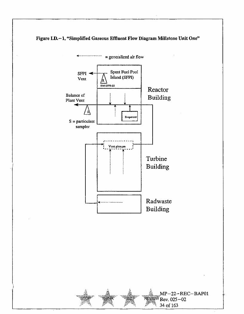
Figure I.D.-1, "Simplified Gaseous Effluent Flow Diagram Millstone Unit One"
4 ..................... = generalized air flow
Balance ofPlant Vent
ReactorBuilding
S
TurbineBuilding
RadwasteBuilding
STOP Ti-q14A MP-22-REC-BAP01
RyiW Rev. 025-0234 of 163

Figure I.D.-2, "Simplified Gaseous Effluent Flow Diagram Millstone Unit Two"
Steam Generator Blowdown Tank Vent
VentRad Monitor(RM8132ANB)
Turbine BldgIN Turbine Bldg Roof Vent
f
OR~ WAN-A
MP-22-REC-BAP011EMI•Rev. 025-02
35 of 163
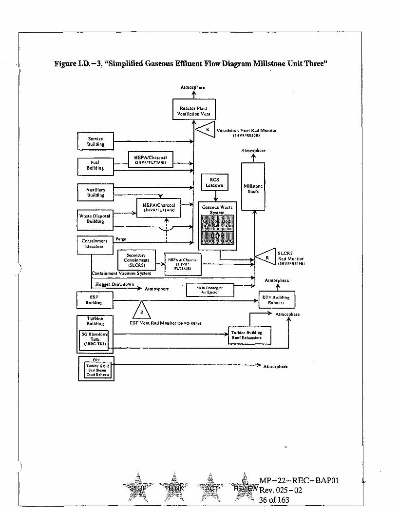
Figure I.D.-3, "Simplified Gaseous Effluent Flow Diagram Millstone Unit Three"
T"h ACT :A' M P-22-REC-BAP01'"TJ- Rev. 025-02
36 of 163

I.E. Radiological Environmental Monitoring
1. Sampling and Analysis
The radiological sampling and analyses provide measurements of radiationand of radioactive materials in those exposure pathways and for thoseradionuclides which lead to the highest potential radiation exposures ofindividuals resulting from plant operation. This monitoring program therebysupplements the radiological effluent monitoring program by verifying thatthe measurable concentrations of radioactive materials and levels ofradiation are not higher than expected on the basis of the effluentmeasurements and modeling of the environmental exposure pathways.Program changes may be made based on operational experience.
The sampling and analyses shall be conducted as specified in Table I.E.-Ifor the locations shown Table I.E.-2. Deviations are permitted from therequired sampling schedule if specimens are unobtainable due to hazardousconditions, seasonal unavailability, malfunction of automatic samplingequipment or other legitimate reasons. If specimens are unobtainable due tosampling equipment malfunction, every effort shall be made to completecorrective action prior to the end of the next sampling period.
All deviations from the sampling schedule shall be documented in theAnnual Radiological Environmental Operating Report pursuant toSection I.E.1 It is recognized that, at times, it may not be possible orpracticable to continue to obtain samples of the media of choice (excludingmilk) at the most desired location or time. In these instances suitablealternative media and locations may be chosen for the particular pathways inquestions and appropriate substitutions made within 30 days in theradiological environmental monitoring program.
If milk samples are temporarily unavailable from any one or more of themilk sample locations required by Table I.E.-2, a grass sample shall besubstituted during the growing season (Apr. - Dec.) and analyzed forgamma isotopes and 1-131 until milk is again available. Upon notificationthat milk samples will be unavailable for a prolonged period (> 9 months)from any one or more of the milk sample locations required by Table I.E. -2,a suitable replacement milk location shall be evaluated and appropriatechanges made in the radiological environmental monitoring program.Reasonable attempts shall be made to sample the replacement milk locationprior to the end of the next sampling period. Any of the above occurrencesshall be documented in the Annual Radiological Environmental OperatingReport, which is submitted'to the U. S. Nuclear Regulatory Commissionprior to May 1 of each year.
Changes to sampling locations shall be identified in a revised Table I.E.-2and, as necessary, Figure(s) I.E.- 1 through I.E.-3.
A MP-22-REC-BAPO1TOAT REX Rev. 025-02
37 of 163
If the level of radioactivity in an environmental sampling medium at one ormore of the locations specified in Table I.E.-2 exceeds the report levels ofTable I.E.-3 when averaged over any calendar quarter, prepare and submitto the Commission within 30 days from the end of the affected calendarquarter, a Special Report which includes an evaluation of any releaseconditions, environmental factors or other aspects which caused the limits ofTable I.E.-3 to be exceeded. When more than one of the radionuclides inTable I.E.-3 are detected in the sampling medium, this report shall besubmitted if:
concentration (1) concentration (2)reporting level (1) reporting level (2)
When radionuclides other than those in Table I.E.-3 are detected and arethe result of plant effluents, this report shall be submitted if the potentialannual dose to an individual is equal to or greater than the appropriatecalendar year limit of the Radiological Effluent Controls (Sections III.D.L.b.,III.D.2.b., or III.D.2.c. for Unit 1; Sections IV.D.1.b., IV.D.2.b., or IV.D.2.c.for Unit 2; and Sections V.D.1.b., V.D.2.b., or V.D.2.c. for Unit 3). Thisreport is not required if the measured level of radioactivity was not the resultof plant effluents, however, in such an event, the condition shall be reportedand described in the Annual Radiological Environmental Operating Report.
The detection capabilities required by Table I.E.-4 are state-of-the-art forroutine environmental measurements in industrial laboratories. It should berecognized that the LLD is defined as an a priori (before the fact) limitrepresenting the capability of a measurement system and not as ana posteriori (after the fact) limit for a particular measurement. All analysesshall be performed in such a manner that the stated LLDs will be achievedunder routine conditions. Occasionally background fluctuations, unavoidablysmall sample sizes, the presence of interfering nuclides, or otheruncontrollable circumstances may render these LLDs unachievable. In suchcases, the contributing factors will be identified and described in the AnnualRadiological Environmental Operating Report.
0. . . . . . . MP-22-REC-BAP01STOP. is .. E. Rev. 025-02
1.. "38 of 163
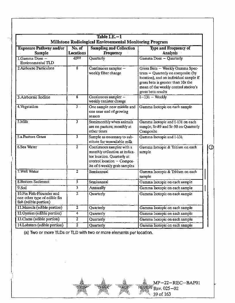
Table I.E.- 1Millstone Radiological Environmental Monitoring Program
Exposure Pathway and/or No. of Sampling and Collection lype and Frequency ofSample Locations Frequency Analysis
1.Gamma Dose - 40(a) Quarterly Gamma Dose - QuarterlyEnvironmental TLD
2.Airborne Particulate 8 Continuous sampler - Gross Beta - Weekly Gamma Spec-weekly filter change trum - Quarterly on composite (by
location), and on individual sample ifgross beta is greater than 10x themean of the weekly control station'sgross beta results
3.Airborne Iodine 8 Continuous sampler - 1-131 - Weeklyweekly canister change
4.Vegetation 5 One sample near middle and Gamma Isotopic on each sampleone near end of growingseason
5.Milk 3 Semimonthly when animals Gamma Isotopic and 1-131 on eachare on pasture; monthly at sample; Sr-89 and Sr-90 on Quarterlyother times Composite
5.a.Pasture Grass 3 Sample as necessary to sub- Gamma Isotopic and 1-131stitute for unavailable milk
6.Sea Water 2 Continuous sampler with a Gamma Isotopic & Tritium on eachmonthly collection at indica- sampletor location. Quarterly atcontrol location - Compos-ite of 6 weekly grab samples
7.Well Water 2 Semiannual Gamma Isotopic & Tritium on eachsample
8.Bottom Sediment 5 Semiannual Gamma Isotopic on each sample9.Soil 3 Annually Gamma Isotopic on each sample10.Fin Fish-Flounder and 2 Quarterly Gamma Isotopic on each sampleone other type of edible finfish (edible portion)11.Mussels (edible portion) 2 Quarterly Gamma Isotopic on each sample12.Oysters (edible portion) 4 Quarterly Gamma Isotopic on each sample13.Clams (edible portion) 2 Quarterly Gamma Isotopic on each sample14.Lobsters (edible portion) 2 Quarterly Gamma Isotopic on each sample
(a) Two or more TLDs or TLD with two or more elements per location.
,7 ...-T T
ý!!V'T
AMP-22-REC-BAP01
"W Rev. 025-0239 of 163
V

Table I.E.-2Environmental Monitoring Program Sampling Locations
The following lists the environmental sampling locations and the types of samples obtained at eachlocation. Sampling locations are also shown on Figures I.E.-1 and I.E.-2:
Location Direction & Dis- Sample Typestance from Re-
No* Name lease Point**
"1-I Onsite - Old Millstone Road 0.6 Mi, NNW TLD, Air Particulate, Iodine, Vegetation72-1 Onsite - Weather Shack 0.3 Mi, S TLD, Air Particulate, Iodine3-1 Onsite - Bird Sanctuary 0.3 Mi, NE TLD, Air Particulate, Iodine, Soil4-I Onsite - Albacore Drive 1.0 Mi, N TLD, Air Particulate, Iodine, Soil5-I Onsite - MP3 Discharge 0.1 Mi, SSE TLD6-I Onsite - Quarry Discharge 0.3 Mi, SSE TLD7-I Onsite - Environmental Lab Dock 0.3 Mi, SE TLD8-I Onsite - Environmental Lab 0.3 Mi, SE TLD9-I Onsite - Bay Point Beach 0.4 Mi, W TLD10-I Pleasure Beach 1.2 Mi, E TLD, Air Particulate, Iodine, Vegetation11-I New London Country Club 1.6 Mi, ENE TLD, Air Particulate, Iodine12-C Fisher's Island, NY 8.0 Mi, ESE TLD13-C Mystic, CT 11.5 Mi, ENE TLD14-C Ledyard, CT 12.0 Mi, NE TLD, Soil15-C Norwich, CT 14.0 Mi, N TLD, Air Particulate, Iodine16-C Old Lyme, CT 8.8 Mi, W TLD17-1 Site Boundary 0.5 Mi, NE Vegetation21-I Goat Location No. 1 2.0 Mi., N Milk22-I Goat Location No. 2 2.7 Mi, NE Milk24-C Goat Location No. 3 29 Mi, NNW Milk25-I Fruits & Vegetables Within 10 Miles Vegetation26-C Fruits & Vegetables Beyond 10 Mi Vegetation27-1 Niantic 1.7 Mi, WNW TLD, Air Particulate, Iodine28-I TWo Tree Island 0.8 Mi, SSE Mussels, Fish'29-I West Jordan Cove 0.4 Mi, NNE Clams, Fish1
30-I Niantic Shoals 1.5 Mi, NNW Mussels31-1 Niantic Shoals 1.8 Mi, NW Bottom Sediment, Oysters32-I Vicinity of Discharge2 Bottom Sediment, Oysters, Lobster, Fish',
Seawater33-1 Seaside Point 1.8 Mi, ESE Bottom Sediment34-I Thames River Yacht Club 4.0 Mi, ENE Bottom Sediment35-I Niantic Bay 0.3 Mi, WNW Lobster, Fish36-I Black Point 3.0 Mi, WSW Oysters37-C Giant's Neck 3.5 Mi, WSW Bottom Sediment, Oysters, Seawater38-I Waterford Shellfish Bed No. 1 1.0 Mi, NW Clams41-I Myrock Avenue 3.2 Mi, ENE TLD42-I Billow Road 2.4 Mi, WSW TLD
i4 MP-22-REC-BAPO1... •hJK •"....`A R Rev. 025-02
40 of 163

Table I.E.-2, Cont.Location Direction & Dis- Sample lypes
tance from Re-No* Name lease Point**
43-I Black Point 2.6 Mi, SW TLD44-I Onsite - Schoolhouse 0.1 Mi, NNE TLD45-I Onsite Access Road 0.5 Mi, NNW TLD46-1 Old Lyme - Hillcrest Ave. 4.6 Mi, WSW TLD47-I East Lyme - W Main St. 4.5 Mi, W TLD48-I East Lyme - Corey Rd. 3.4 Mi, WNW TLD49-1 East Lyme - Society Rd. 3.6 Mi, NW TLD50-I East Lyme - Manwaring Rd. 2.1 Mi, W TLD51-I East Lyme - Smith Ave. 1.5 Mi, NW TLD52-I Waterford - River Rd. 1.1 Mi, NNW TLD53-I Waterford - Gardiners Wood Rd. 1.4 Mi, NNE TLD55-1 Waterford - Magonk Point 1.8 Mi, ESE TLD56-I New London - Mott Ave. 3.7 Mi, E TLD57-I New London - Ocean Ave. 3.6 Mi, ENE TLD59-I Waterford -Miner Ave. 3.4 Mi, NNE TLD60-I Waterford - Parkway South 4.0 Mi, N TLD61-I Waterford - Boston Post Rd. 4.3 Mi, NNW TLD62-I East Lyme - Columbus Ave. 1.9 Mi, WNW TLD63-I Waterford - Jordon Cove Rd. 0.8 Mi, NE TLD64-I Waterford - Shore Rd. 1.1 Mi, ENE TLD65-I Waterford - Bank St. 3.2 Mi, NE TLD71-I Onsite well Onsite Well water72-I Onsite well Onsite Well water
' Fish to be sampled from one of three locations -28, 29, or -32.2Vicinity of discharge includes the Quarry and shoreline area from Fox Island to western pointof Red Barn Recreation Area and offshore out to 500 feet.
* I = Indicator; C = Control.
** - The release points are the Millstone Stack for terrestrial locations and the end of the quarry foraquatic location.
NOTE: Environmental TLDs also function as accident TLDs in support of the Millstone Emergency Plan.
r'l ¢•MP-22-REC-BAP01THINKT MA•T Rev. 025-02
41 of 163

Figure I.E.-1, "Inner Air Particulate And Vegetation Monitoring Stations"
..- . ..:. Niahtlc River 53
t.1
~~P*~~ 4S 5 T†*'~~Nani Bay ';. ~~JrnCv
ww*Wr5 z
.,I ....
an Air : Mo "'~m ('atiu" te & Jone)'
iTerrestral Monitoring (lkrasfruitI & vegeta~bles, s~ofllor eaves)'IK
"- -. rsed.me fl, a , or lobster).... ... :".
:+t ,3 11 m u s t !
"
MP-22-REC-BAPOI-TP M-1~ Rev. 025-02
9 42 of 163

Figure I.E.-2, "Outer Terrestrial Monitoring Stations"
..... ..... -.- ./ . •• -.
NA
,,' 0 -. •*S Milesmie
4 Es
42~1
* I~~ "~ '"..%..'fl9:Ia
RE1L Moni onn
-i .: ..,t.(
Ter-re..n - .o..t.rn.g (m l..a s ti i~ ~ b t b e . s i... le v.)..
Sc... ..... .. , y s e .a rn.o r l o s t r . . .! . - _ . .
AP E~ MP-22-REC-BAP01THINK ACT ~ Rev. 025-02
43 of 163

Table I.E.-3Reporting Levels For Radioactivity Concentrations In Environmental Samples
Analysis Water Airborne- Fish ShellfishC" Milk Vegetables.(pCi/l) Particulate Shellfish (pCi/g, Wet) (pCi/l) (pCi/g, Wet)
or Gases (pCi/g, wet)(pCi/m3 )
H-3 20,000A.
Mn-54 1,000 30 140
Fe-59 400 10 60
Co-58 1,000 30 130
Co-60 300 10 50Zn-65 300 20 80Zr-95 400
Nb-95 400Ag-lr0m 8 30
1-131. 2 0 B. 0.9 0.2 1 3 0.1
Cs-134 30 10 1 5 60 1
Cs-137 50 20 2 8 70 2
Ba-140 200 300
La-140 200 300
A. 20,000 pCi/I for drinking water samples. (This is 40 CFR Part 141 value.) For non-drinkingwater pathways (i.e., seawater), a value of 30,000 pCi/I may be used.
B. Reporting level for 1-131 applies to non-drinking water pathways (i.e., seawater). If drinkingwater pathways are sampled, a value of 2 pCi/I is used.
C. For on-site samples, these values can be multiplied by 3 to account for the near field dilutionfactor
7, . MP-22-REC-BAP01•l• j n R Rev. 025-02
44 of 163

Table I.E.-4Maximum Values For Lower Limits Of Detection (LLD)A"
Analysis Water Airborne- Fish Milk Food Sediment(pCi/l) Particulate Shellfish (pCi/1) Products (pCi/g, dry)
or Gases (pCi/g, wet) (pCi/g, wet)(pCi/m3)
gross beta 1 x 10⁻²
H-3 2000D.
Mn-54 15 0.130
Fe-59 30 0.260
Co-58, 60 15 0.130
Zn-65 30 0.260
Zr-95 30
Nb-95 15
1-131 15C. 7 x 10- 2 1 0.06B.
Css-134 15 5 x 10- 2 0.130 15 0.060 0.150
Cs-137 18 6 x 10- 2 0.150 18 0.080 0.180
Ba- 140 60C. 70
La-140 15c- 25
TABLE NOTATIONSTable I.E.-4
A. The LLD is the smallest concentration of radioactive material in a sample that will be detectedwith 95% probability with 5% probability of falsely concluding that a blank observationrepresents a "real" signal.
For a particular measurement system (which may include radiochemical separation):
4.66 Sb
(E)(V)(2.22)(Ye--')
Where:
o LLD is the lower limit of detection as defined above (as liCi per unit mass or volume)
* Sb is the standard deviation of the background counting rate or of the counting rate of a blanksample as appropriate (as counts per minute)
* E is the counting efficiency (as counts per transformation)
* V is the sample size (in units of mass or volume)
* 2.22 is the number of transformations per minute per pCi
o Y is the fractional radiochemical yield (when applicable)
AIR& MP-22-REC-BAP01[Rev. 025-02
45 of 163

a ) is the radioactive decay constant for the particular radionuclide
* At is the elapsed time between midpoint of sample collection and midpoint of counting time (orend of the sample collection period) and time of counting.
It should be recognized that the LLD is defined as an a priori (before the fact) limit representingthe capability of a measurement system and not as an a posteriori (after the fact) limit for aparticular measurement.
Analyses shall be performed in such a manner that the stated LLDs will be achieved underroutine conditions. Occasionally background fluctuations, unavoidably small sample sizes, thepresence of interfering nuclides, or other uncontrollable circumstances may render these LLDsunachievable. In such cases, the contributing factors will be identified in the AnnualRadiological Environmental Operating Report.
B. LLD for leafy vegetables.
C. From end of sample period.
D. If no drinking water pathway exists (i.e., seawater), a value of 3,000 pCi/I may be used.
..'- .
MP-22-REC-BAP01
F VIEWRev. 025 02
46 of 163

2. Land Use Census
The land use census ensures that changes in the use of unrestricted areas areidentified and that modifications to the monitoring.program are made ifrequired by the results of this census. This census satisfies the requirementsof Section IVB.3 of Appendix I to 10 CFR 50. The land use census shall bemaintained and shall identify the location of the nearest resident, nearestgarden*, and milk animals in each of the 16 meteorological sectors within adistance Of five miles.
The validity of the land use census shall be verified within the last half ofevery year by either a door-to-door survey, aerial survey, consulting localagriculture authorities, or any combination of these methods.
With a land use census identifying a location(s) which yields a calculateddose or dose commitment greater than the doses currently being calculatedin the off-site dose models, make the appropriate changes in the samplelocations used.
With a land use census identifying a location(s) which has a higher D/Q thana current indicator location the following shall apply:
1) If the D/Q is at least 20% greater than the previously highest D/Q,replace one of the present sample locations with the new one within 30days if milk is available.
2) If the D/Q is not 20% greater than the previously highest D/Q, considerdirection, distance, availability of milk, and D/Q in deciding whether toreplace one of the existing sample locations. If applicable, replacementshall be within 30 days. If no replacement is made, sufficient justificationshall be given in the annual report.
Sample location changes shall be noted in the Annual RadiologicalEnvironmental Operating Report.
*Broad leaf vegetation (a composite of at least 3 different kinds ofvegetation) may be sampled at the site boundary in each of 2 differentdirection sectors with high D/Qs in lieu of a garden census.
3. Interlaboratory Comparison Program
The Interlaboratory Comparison Program is provided to ensure thatindependent checks on the precision and accuracy of the measurements ofradioactive material in environmental sample matrices are performed as partof a quality assurance program for environmental monitoring in order todemonstrate that the results are reasonably valid.
S.... MP-22-REC-BAP01
'N' R5I X# Rev. 025-0247 of 163

Analyses shall be performed on radioactive materials supplied as part of anInterlaboratory Comparison Program. A summary of the results obtained aspart of the above required Interlaboratory Comparison Program shall beincluded in the Annual Radiological Environmental Operating Report.
With analyses not being performed as required above, report the correctiveactions taken to prevent a recurrence to the Commission in the AnnualRadiological Environmental Operating Report.
4. Bases for the Radiological Environmental Monitoring Program
Federal regulations (10 CFR Parts 20 and 50) require that radiologicalenvironmental monitoring programs be established to provide data onmeasurable levels of radiation and radioactive materials in the site environs.In addition, Appendix I to 10 CFR 50 requires that the relationship betweenquantities of radioactive material released in effluents during normaloperation, including anticipated operational occurrences, and the resultantradiation doses to individuals from principal pathways of exposure beevaluated. The Millstone Environmental Radiological Monitoring Program(REMP) has been established to verify the effectiveness of in-plant measuresused for controlling the release of radioactive materials from the plant, aswell as provide for the comparison of measurable concentrations ofradioactive materials found in the environment with expected levels based oneffluent measurements and the modeling of the environmental exposurepathways.
The REMP detailed in Table I.E. -1 provides measurements of radioactivematerials or exposures in the environment along all principal exposurepathways to man that could be impacted by plant effluents. These includedirect radiation exposure, inhalation exposure, and ingestion of foodproducts (both aquatic and land grown). In addition, intermediate mediasuch as vegetation and bottom sediments are included as potential earlyindicators of radioactive material buildup. The selections of samplelocations include areas subject to plant effluents that would be expected toexhibit early indication of any buildup of plant related radioactive materials.
The required detection capabilities for environmental sample analyses aretabulated in terms of lower limits of detection (LLDs). Except for Ba- 140and La-140 in milk, the required LLDs are from NUREGs-1301 and 1302.The NUREGs specify an LLD of 15 pCi/1 for the parent-daughtercombination of Ba-La-140. An LLD of 25 pCi/l is specified for thedaughter La-140 and 70 pCi/1 for the parent Ba-140.
.-- MP-22-REC-BAP01:M-1 T Rev. 025-02
48 of 163

Annual reports of environmental radiation monitoring summaries are filedwith the NRC in accordance with the requirements of 10 CFR 50.36b and theguidance contained in Regulatory Guide 4.8, Environmental TechnicalSpecifications for Nuclear.Power Plant," and NUREG-0472(NUREG-0473) Revision 3, "Standard Radiological Effluent TechnicalSpecifications for Pressurized Water Reactors (Boiling Water Reactors)."
I.E Report Content
1. Annual Radiological Environmental Operating Report
The Annual Radiological Environmental Operating Report shall includesummaries, interpretations, and statistical evaluation of the results of theradiological environmental surveillance activities for the report period,including a comparison with previous environmental surveillance reports andan assessment of the observed impacts of the plant operation on theenvironment. The report shall also include the results of the land use censusrequired by Section I.E.2. of this manual. If levels of radioactivity aredetected that result in calculated doses greater than 1OCFR50 Appendix IGuidelines, the report shall provide an analysis of the cause and a plannedcourse of action to alleviate the cause.
The report shall include a summary table of all radiological environmentalsamples which shall include the following information for each pathwaysampled and each type of analysis:
1) Total number of analyses performed at indicator locations.
2) Total number of analyses performed at control locations.
3) Lower limit of detection (LLD).
4) Mean and range of all indicator locations together.
5) Mean and range of all control locations together.
6) Name, distance and direction from discharge, mean and range for thelocation with the highest annual mean (indicator or control).
7) Number of non-routine reported measurements as defined in thesespecifications.
In the event that some results are not available for inclusion with the report,the report shall be submitted noting and explaining the reasons for themissing results. The missing data shall be submitted in the next annualreport.
AA MP-22-REC-BAPO1STOP A, CTRev. 025-02
49 of 163

This report shall include a comparison of dose assessments of the measuredenvironmental results of the calculated effluent results to confirm the relativeaccuracy or conservatism of effluent monitoring dose calculations.
The report shall also include a map of sampling locations keyed to a tablegiving distances and directions from the discharge; the report shall alsoinclude a summary of the Interlaboratory Comparison Data required bySection I.E.3. of this manual.
2. Radioactive Effluent Release Report
The Radioactive Effluent Release Report (RERR) shall include quarterlyquantities of and an annual summary of radioactive liquid and gaseouseffluents released from the unit in the Regulatory Guide 1.21 (Rev. 1, June1974) format. Radiation dose assessments for these effluents shall beprovided in accordance with 10 CFR 50.36a and the Radiological EffluentControls. An annual assessment of the radiation doses from the site to themost likely exposed REAL MEMBER OF THE PUBLIC shall be includedto demonstrate conformance with 40 CFR 190. Gaseous pathway doses shalluse meteorological conditions concurrent with the quarter of radioactivegaseous effluent releases. Doses shall be calculated in accordance with theOffsite Dose Calculation Manual. The licensee shall maintain an annualsummary of the hourly meteorological data (i.e., wind speed, wind directionand atmospheric stability) either in the form of an hour-by-hour listing ona magnetic medium or in the form of a joint frequency distribution. Thelicensee has the option of submitting this annual meteorological summarywith the RERR or retaining it and providing it to the NRC upon request.The RERR shall be submitted prior to May 1 of each year for the periodcovering the previous calendar year.
The RERR shall include a summary of each type of solid radioactive wasteshipped offsite for burial or final disposal during the report period and shallinclude the following information for each type:
" type of waste (e.g., spent resin, compacted dry waste, irradiatedcomponents, etc.)
* solidification agent (e.g., cement)
o total curies
" total volume and typical container volumes
* principal radionuclides (those greater than 10% of total activity)
0 types of containers used (e.g., LSA, Type A, etc.)
-- 7,-Nt ..MP-22-REC-BAP01STOP ..... I( Ag REI-REW Rev 025-02
S50 of 163

The RERR shall include a list of all abnormal releases of radioactivegaseous and liquid effluents (i.e., all unplanned or uncontrolled radioactivityreleases, including reportable quantities) from the site to unrestricted areas.Refer To MP-22-REC-REF03, "REMODCM Technical InformationDocument (TID)," for guidance on classifying releases as normal orabnormal. The following information shall be included for each abnormalrelease:
" total number of and curie content of releases (liquid and gas)
• a description of the event and equipment involved
* cause(s) for the abnormal release
" actions taken to prevent recurrence
" consequences of the abnormal release
Changes to the MP-22-REC-BAP01, "Radiological Effluent MonitoringAnd Offsite Dose Calculation Manual (REMODCM)," shall be submitted tothe NRC as appropriate, as a part of or concurrent with the RERR for theperiod in which the changes were made.
ThN-K'"
MP-22-REC-BAP01
ACT REWRev. 025-02
51 of 163

SECTION II.
Offsite Dose Calculation Manual (ODCM)
For theMillstone Nuclear Power Station
Nos. 1, 2, & 3
Docket Nos. 50-245, 50-336, 50-423
........ s ....... •: ,+: MP- 22- R E C - BA POI
Re ". 025-02- 52 of 163
I1

0SECTION II. OFF-SITE DOSE CALCULATION MANUAL (#DCM)
II.A. Introduction
The purpose of the Off-Site Dose Calculation Manual (Section II of theREMODCM) is to provide the parameters and methods to be used in calculatingoffsite doses and effluent monitor setpoints at the Millstone Nuclear PowerStation. Included are methods for determining maximum individual whole bodyand organ doses due to liquid and gaseous effluents to assure compliance withthe regulatory dose limitations in 10 CFR 50, Appendix I. Also included aremethods for performing dose projections to assure compliance with the liquidand gaseous treatment system operability sections of the Radiological EffluentMonitoring Manual (REMM - Section I of the REMODCM). The manual alsoincludes the methods used for determining quarterly and annual doses forinclusion in the Radioactive Effluent Release Report.
The bases for selected site-specific factors used in the dose calculationmethodology are provided in MP-22-REC-REF03, "REMODCM TechnicalInformation."
Another section of this manual discusses the methods to be used in determiningeffluent monitor alarm/trip setpoints to be used to ensure compliance with theinstantaneous release rate limits in Sections III.D.2.a., IVD.2.a., and VD.2.a. I®This manual includes the methods to be used in performance of the surveillancerequirements in the Radiological Effluent Controls of Sections III, IV, and VAppendix A, Tables App.A-1 provide a cross-reference of effluent requirementsand applicable methodologies contained in the REMODCM.
Most of the calculations in this manual have several methods given for thecalculation of the same parameter. These methods are arranged in order ofsimplicity and conservatism, Method 1 being the easiest and most conservative.As long as releases remain low, one should be able to use Method 1 as a simpleestimate of the dose. If release calculations approach the limit, however, moredetailed yet less conservative calculations may be used. At any time a moredetailed calculation may be used in lieu of a simple calculation.
This manual is written common to all three units since some release pathways areshared and there are also site release limits involved. These facts make itimpossible to completely separate the three units.
II.B. Responsibilities
All changes to the Off-Site Dose Calculation Manual (ODCM) shall be reviewedand approved by the Site Operations Review Committee prior toimplementation.
RAI .. MP-22-REC-BAP01S"EO •Ti~K CT~ R_.Rev. 025-02
"""*. 53 of 163

All changes and their rationale shall be documented in the Radioactive EffluentRelease Report.
It shall be the responsibility of the Vice President and Senior Nuclear Executive- Millstone to ensure that this manual is used as required by the administrativecontrols of the Technical Specifications. The delegation of implementationresponsibilities is delineated in the MP-22-REC-PRG, "Radiological EffluentControl."
II.C. Liquid Dose Calculations
The determination of potential doses from liquid effluents to the maximumexposed member of the public is divided into two methods. Method 1 is asimplified calculation approach that is used as an operational tool to ensure thateffluent releases as they occur are not likely to cause quarterly and annual offsitedose limits to be exceeded. Effluent doses are calculated at least once every 31days. Method 2 is a more detailed computational calculation using acceptedcomputer models to demonstrate actual regulatory dose compliance. Method 2 isused whenever the Method 1 estimation begins to approach a regulatory limit,and for preparation of the Radioactive Effluent Release Report, which includesthe quarterly and annual dose impacts for all effluents recorded discharged to theenvironment during the year of record.
1. Whole Body Dose from Liquid Effluents
Radiological Effluent Controls (Sections III, IV, and V) limit the whole bodydose to an individual member of the public to 1.5 mrem per calendar quarterand 3 mrem per year from liquid effluents released from each unit. (SeeAppendix A, Table App.A- 1 for cross-reference effluent control I@requirements and applicable sections in the REMODCM which are used todetermine compliance). In addition, installed portions of liquid radwastetreatment system are required to be operated to reduce radioactive materialsin liquid effluents when the projected whole body dose over 31 days fromapplicable waste streams exceeds 0.006 mrem. This part of the REMODCMprovides the calculation methodology for determining the whole body dosefrom radioactive materials released into liquid pathways of exposureassociated with routine discharges. This includes the liquid pathways whichcontribute to the 25 mrem annual total dose limit (40 CFR190) to any realindividual member of the public from all effluent sources (liquids, gases, anddirect).
a. Method 1 (Applicable to Units 1, 2, and 3)
For Unit 1: No Method 1, use Method 2 (Section II.C.l.b.)
D--. MP-22-REC-BAP01
R -NW Rev 025-02
54 of 163

For Units 2 and 3:.
Dw= 0.2 CF+ 5.6 x 10-' CH
Where:
DW= The estimated whole body dose to a potentially maximumexposed individual (in mrem) due to fission and activationproducts released in liquid effluents during a specified timeperiod.
CF = total gross curies of fission and activation products,excluding tritium and dissolved noble gases, released duringthe period of interest.
CH = total curies of tritium released during the period of interest.
If DW, within a calendar quarter is greater than 0.5 mrem, go toMethod 2.
b. Method 2 (Applicable to Units 1, 2, and 3)
If the calculated dose using Method 1 is greater than 0.5 mrem within acalendar quarter, or if a more accurate determination is desired, use theNRC-computer code LADTAP II, or a code which uses the methodologygiven in Regulatory Guide 1.109, to calculate the liquid whole bodydoses. Method 2 (LADTAP II) is also used in the performance of dosecalculations for the Radioactive Effluent Release Report. The use ofthis code is given in MP-22-REC-GDLO2, "Liquid Dose Calculations- LADTAP-II." Additional information on LADTAPII is contained inMP-22- REC- REF03, "REMODCM Technical Information Manual."
2. Maximum Organ Dose from Liquid Effluents
Radiological Effluent Controls (Sections III, IV, and V) limit the maximumorgan dose to an individual member of the public to 5 mrem per calendarquarter and 10 mrem per year from liquid effluents released from each unit.(See Appendix A, Table App.A- 1 for cross-reference effluent control I®requirements and applicable sections in the REMODCM which are used todetermine compliance). In addition, installed portions of liquid radwastetreatment system are required to be operated to reduce radioactive materialsin liquid effluents when the projected maximum organ dose over 31 daysfrom applicable waste streams exceeds 0.02 mrem. This part of theREMODCM provides the calculation methodology for determining themaximum organ dose from radioactive materials released into liquidpathways of exposure associated with routine discharges. This includes the
. .. MP-22-REC--BAP01THNK.......m RtIW Rev. 025-02
S55 of 163

liquid pathways which contribute to the 25 mrem annual organ (except 75mrem thyroid) dose limit (40 CFR190) to any real individual member of thepublic from all effluent sources (liquids, gases, and direct).
a. Method 1 (Applicable to Units 1, 2, and 3)
For Unit 1: No Method 1, use Method 2 (Section II.C.2.b.)
For Units 2 and 3:
Do = 1.5 CF
Where: Do =The estimated maximum organ dose to the potentiallymaximum exposed individual (in mrem) due to fission and activationproducts released in liquid effluents during a specified time period.
CF =total gross curies of fission and activation products, excludingtritium and dissolved noble gases, released during the period ofinterest - same as Section II.C.L.a.
If Do, within a calendar quarter is greater than 2 mrem, go to Method 2.
b. Method 2 (Applicable to Units 1, 2, and 3)
If the calculated dose using Method 1 is greater than 2 mrem, or if amore accurate determination is desired, use the NRC computer codeLADTAP II, or a code which uses the methodology.given in RegulatoryGuide 1.109, to calculate the liquid maximum organ doses. Method 2(LADTA-P II) is also used in the performance of dose calculations for theRadioactive Effluent Release Report. The use of this code and the inputparameters are given in MP-22- REC-GDL02, "Liquid DoseCalculations - LADTAP-II." Additional information on LADTAPII iscontained in MP-22-REC-REF03, "REMODCM TechnicalInformation Manual."
3. Estimation of Annual Whole Body Dose (Applicable to All Units)
An estimation of annual (year-to-date) whole body dose (Dyw) fromliquid effluents shall be made every month to determine compliance with theannual dose limits for each Unit which releases any radioactivity in liquideffluents. Annual doses will be determined as follows:
Dyw= Dw
Where the sum of the doses include the whole body dose contribution fromall effluent releases for each Unit recorded to-date. For estimation of the
MP-22--REC-BAP01T-JW. " f"?-W Rev. 025-02
. 56 of 163

Total Dose requirements of 40CFR190, the effluent releases from all threeUnits combined are used.
The following shall be used as Dw.
1) If the detailed quarterly dose calculations required per Section II.C.6.for the Radioactive Effluent Release Report are completed for anycalendar quarter, use that result.
2) If the detailed calculations are not complete for a particular quarter, usethe results as determined in Section II.C.1.
3) If the annual dose estimate, Dyw is greater than 3 mrem and any Dwdetermined as in Section II.C.1. was not calculated using Method 2(i.e., LADTAP II computer code or a Regulatory Guide 1.109 code),recalculate Dw using Method 2 if this could reduce Dyw to less than3 mrem.
4. Estimation of Annual Maximum Organ Dose (Applicable to All Units)
An estimation of annual (year-to-date) maximum organ dose (Dyo) fromliquid effluents shall be made every month to determine compliance with theannual dose limits for each Unit which releases any radioactivity in liquideffluents. Annual doses will be determined as follows:
Dyo = TDo
Where the sum of the doses include the maximum organ dose contributionfrom all effluent releases for each Unit recorded to-date. For estimation ofthe Total Dose requirements of 40CFR190, the effluent releases from allthree Units combined are used.
The following guidelines shall be used:
1) If the detailed quarterly dose calculations required per Section II.C.6.for the Radioactive Effluent Release Report are completed for anycalendar quarter, use that result.
2) If the detailed calculations are not complete for a particular quarter, usethe results as determined in Section II.C.2.
3) If different organs are the maximum for different quarters, they may besummed together and Dyo can be recorded as a less than value as longas the value is less than 10 mrem.
fl A .. MP-22-REC-BAP01T4R" E Rev. 025-02
57 of 163

4) If Dyo is greater than 10 mrem and any value used in its determinationwas calculated as in Section II.C.2., but not with Method 2 (i.e.,LADTAP II computer code or a Regulatory Guide 1.109 code),recalculate that value using Method 2 if this could reduce Dyo.to lessthan 10 mrem.
5. Monthly Dose Projections
Section I.C.2.a. of the REMM requires that certain portions of the liquidradwaste treatment equipment be used to reduce radioactive liquid effluentswhen the projected doses for each Unit (made at least once per 31 days)exceeds 0.006 mrem whole body or 0.02 mrem to any organ. The followingmethods are applied in the estimation of monthly dose projections:
a. Whole Body and Maximum Organ (Applicable to Unit 1 Only)
In the dose code DOSLIQ use concentrations of radionuclides in reactorcavity water and estimates of projected volumes and discharge rates forthe following 31 days to estimate dose from liquid discharge of reactorcavity water in the following 31 days.
b. Whole Body and Maximum Organ when Steam Generator Total GammaActivity is less than 5E-7 [tCi/ml and Steam Generator Tritium is lessthan 0.02 [tCi/ml (Applicable to Units 2 and 3)
The projected monthly whole body dose (Units 2 or 3) is determinedfrom:
DE'MW = D'MW [RI R 4 F 2]
The monthly projected maximum organ dose (Units 2 or 3) isdetermined from:
DEMO = D'MO [R1 R 4 F 2]
Where:
D'MW =the whole body dose from the last typical* previouslycompleted month as calculated per the methods inSection II.C.1.
D'MO =the maximum organ dose from the last typical* previouslycompleted month as calculated per the methods inSection II.C.2.
-. .. MP-22-REC-BAP01"Tpp "Rev. 025-02
S" 58 of 163

R1 = the ratio of the total estimated volume of liquid batches tobe released in the present month to the volume released inthe past month.
R4 = the ratio of estimated primary coolant activity for thepresent month to that for the past month.
F2 = the factor to be applied to the estimated ratio of final curiesreleased if there are expected differences in treatment ofliquid waste for the present month as opposed to the pastmonth (e.g., bypass of filters or demineralizers).NUREG-0017 or past experience shall be used to determinethe effect of each form of treatment which will vary. F2 = 1if there are no expected differences.
Notes:
1) The last month should be typical without significant operationaldifferences from the projected month. If there were no releasesduring last month, do not use that month as the base month if itis estimated that there will be releases for the coming month.
2) If the last typical month's doses were calculated usingLADTAP II (or similar methodology), also multiply theLADTAP (or similar methodology) doses by R5 where R5 =
total dilution flow from LADTAP run divided by estimated totaldilution flow.
c. Whole Body and Maximum Organ when Steam Generator Total GammaActivity Exceeds 5E-7 VCi/ml or Steam Generator Tritium Exceeds 0.02iCi/ml (Applicable to Units 2 and 3)
The projected monthly whole body dose (Units 2 or 3) is determinedfrom:
DEMW = D'MW [(1 - FI) R1 R4 F2 + F1 R2 R3]
The monthly projected maximum organ dose (Units 2 or 3) isdetermined from:
DEMO =D'Mo [(1 - FI) R, R4 F2 + F1 R2 R31
.MP-22-REC-BAP01.-.- "NK'F -EWRev. 025-02
" -" • 59 of 163

Where:
D'Mw=the whole body dose from the last typical previously iccompleted month as calculated per the methods inSection II.C.1.
D'Mo=the maximum organ dose from the last typical previously I®completed month as calculated per the methods inSection II.C.2.
R, = the ratio of the total estimated volume of liquid batches tobe released in the present month to the volume released inthe past month.
R2 = the ratio of estimated volume of steam generator blowdownto be released in present month to the volume released inthe past month.
F1 = the fraction of curies released last month coming fromsteam generator blowdown calculated as:
curies from blowdowncuries from blowdown + curies from batch tanks
R3 = the ratio of estimated secondary coolant activity for thepresent month to that for the past month.
R4 = the ratio of estimated primary coolant activity for thepresent month to that for the past month.
F2 = the factor to be applied to the estimated ratio of final curiesreleased if there are expected differences in treatment ofliquid waste for the present month as opposed to the pastmonth (e.g., bypass of filters or demineralizers).NUREG-0017 or past experience shall be used to determinethe effect of each form of treatment which will vary. F2 =if there are no expected differences.
6. Quarterly Dose Calculations for Radioactive Effluent Release Report
Detailed quarterly dose calculations required for the Radioactive EffluentRelease Report shall be done using the NRC computer code LADTAP II, ora code which uses the methodology given in Regulatory Guide 1.109. Theuse of this code, and the input parameters are given inMP-22-REC- GDLO2, "Liquid Dose Calculations - LADTAP HI." IAdditional information on LADTAPII is contained inMP-22-REC-REF03, "REMODCM Technical Information Manual."
- .. MP-22-REC-BAP01
THINK !V4 .. W Rev. 025-0260 of 163
7. Bases for Liquid Pathway Dose Calculations
The dose calculation methodology and parameters used in Section II of theREMODCM implement the requirements in Section III.A of Appendix.I(1OCFR50) which states that conformance with the dose objectives ofAppendix I be shown by calculational procedures based on models and data,such that the actual exposure of a member of the public through appropriatepathways is unlikely to be substantially underestimated. The doseestimations calculated by both Method 1 and Method 2 are based on theliquid models presented in Regulatory Guide 1.109, Rev.1; "Calculation ofAnnual Doses to Man from Routine Releases of Reactor Effluents for thePurpose of Evaluating Compliance with 10CFR Part 50, Appendix I". Theseequations are implemented via the use of the NRC sponsored computer codeLADTAP II. Input parameter values typically used in the dose models arelisted in MP-22-REC-REF03, "REMODCM Technical InformationDocument." This same methodology is used in the determination ofcompliance with the 40CFR190 total dose standard for the liquid pathways.
The conversion constants in the Method 1 equations are based on themaximum observed comparison of historical effluent releases for each unitand corresponding whole body or critical organ doses to a maximumindividual. The dose conversion factors are calculated based on the ratio ofthe observed highest dose (whole body and organ) and the curies of fissionand activation products released during the period. This ratio results in theMethod 1 equation conversion factor in mrem/Ci released. This sameapproach was repeated separately for tritium (as a different radionuclideclass) discharged in liquids wastes. MP-22-REC-REF03 describes thederivation of the Method 1 constants and list the historical whole body andmaximum organ doses calculated for each unit operation.
-- •• TM-t-. •.MP-22-REC-BAPO1
°RE-VA"W ' Rev. 025 - 02
-61 of 163

II.D. Gaseous Dose Calculations
The determination of potential release rates and doses from radioactive gaseouseffluents to the maximum off-site receptor are divided into two methods. Method1 provides simplified operational tools to ensure that effluent releases are notlikely to cause quarterly and annual off-site dose or dose rate limits to beexceeded. Effluent doses are calculated at least once every 31 days. Method 2provides for a more detailed computational calculation using accepted computermodels to demonstrate actual regulatory compliance. Method 2 is used wheneverthe Method 1 estimation approaches a regulatory limit, and for preparation ofthe Radioactive Effluent Release Report which includes the quarterly and annualdose impacts for all effluents recorded discharged to the atmosphere during theyear of record.
1. Site Release Rate Limits ("Instantaneous")
Radiological Effluent Controls (Sections III, IV, and V) for each unit requirethat the instantaneous off-site dose rates from noble gases released to theatmosphere be limited such that they do not exceed 500 mrem/year at anytime to the whole body or 3000 mrem/year to the skin at any time from theexternal cloud. For iodine-131, 133, tritium, and particulates (half-lives >8. days), the inhalation pathway critical organ dose rate from all units shallnot exceed 1500 mrem/year at any time. These limits apply to thecombination of releases from all three Units on the site, and are directlyrelated to the radioactivity release rates measured for each Unit. By limitinggaseous release rates for both classes of radionuclides (i.e., noble gases; andiodines, tritium, and particulates) to within values which correlate to theabove dose rate limits, assurance is provided that the Radiological EffluentControls dose rate limits are not exceeded.
a. Method 1 for Noble Gas Release Rate Limits
The instantaneous noble gas release rate limit from the site shall be:
Q1v /90,000 +Q2s]560,000 + Q2v/290,000 + Q3s/560,000 + Q3v/290,000 < 1
Where:
Qjv = Noble gas release rate from Spent Fuel Pool Island Vent([tCi/sec)
Q2s Noble gas release rate from MP2 to Millstone Stack (tCi/sec)
Q2v = Noble gas release rate from MP2 Vent ([tCi/sec)
Q3V = Noble gas release rate from MP3 Vent ([iCi/sec)
Q3S - Noble gas release rate from MP3 to Millstone Stack ([tCi/sec)
T, V MP-22-REC-BAP01R'- -W Rev. 025-02
62 of 163

As long as the above is less than or equal to 1, the doses will be less thanor equal to 500 mrem to the total body and less than 3000 mrem to theskin. The limiting factor for the Unit 1 SFPI vent of 90,000 is based onthe skin dose limit of 3,000 mrem/year, while all the other factors arebased on the whole body dose limit of 500 mrem/year.
b. Method 1 Release Rate Limit - 1-131, 1-133, H-3 and ParticulatesHalf Lives Greater Than 8 Days
With releases satisfying the following limit conditions, the dose rate tothe maximum organ will be less than 1500 mrem/year from theinhalation pathway:
1) The site release rate limit of 1-131, 1-133, and tritium (where thethyroid is the critical organ for these radionuclides) shall be:
DRthyl + DRthy2 + DRthy3 < 1
Where the contribution from each Unit is calculated from:
Unit 1: DRthyl = 9.36 x 10⁻⁶ QH1V
Unit 2: DRthy2 =
Unit 3: DRthy3 =
5.1 x 10-2131QI2v + 2.38 x 10⁻³ 131QI2S +1.25 x 10- 133QI2V+5.75 x 10⁻⁴ 133QI2S +4.2 x 10⁻⁶ QH2V+ 1.9 X 10⁻⁷ QH2S
5.1 x 10⁻²P1QI3v + 2.38 x 10⁻³ 131QI3S +1.25 x 10- 133QI3V +5.75 x 10⁻⁴ 133QI3S +4.2 x 10⁻⁶ QH3V + 1.9 x 10⁻⁷ QH3S
2) The site release rate limit of particulates with half-lives greaterthan 8 days and tritium (where the critical organ is a composite oftarget organs for a mix of radionuclides) shall be:
DRorgi + DRorg2 + DRorg3 < 1
Where the contribution from each Unit is calculated from:
Unit l:DRorgl= 1.05 x 10⁻¹ [Qpi + QP1B ]+9.36 x 1O-6 QH1V
Unit 2:DRorg2 = 2.38 x 10⁻³ QP2S + 5.1 X 10⁻² QP2V + 1.9 X 10⁻⁷
QH2S + 4.2 x 10⁻⁶ QH2V
Unit 3:DRorg3 = 2.38 x 10⁻³ QP3s + 5.1 x 10⁻² QP3V +1.9 x 10⁻⁷ QH3S + 4.2 x 10⁻⁶ QH3V
STP -E1R ~AA#.50 .... .. ..
rs- - '7,:-_- AA .....
MP-22-REC-BAP01RWRev. 025-02
S63 of 163
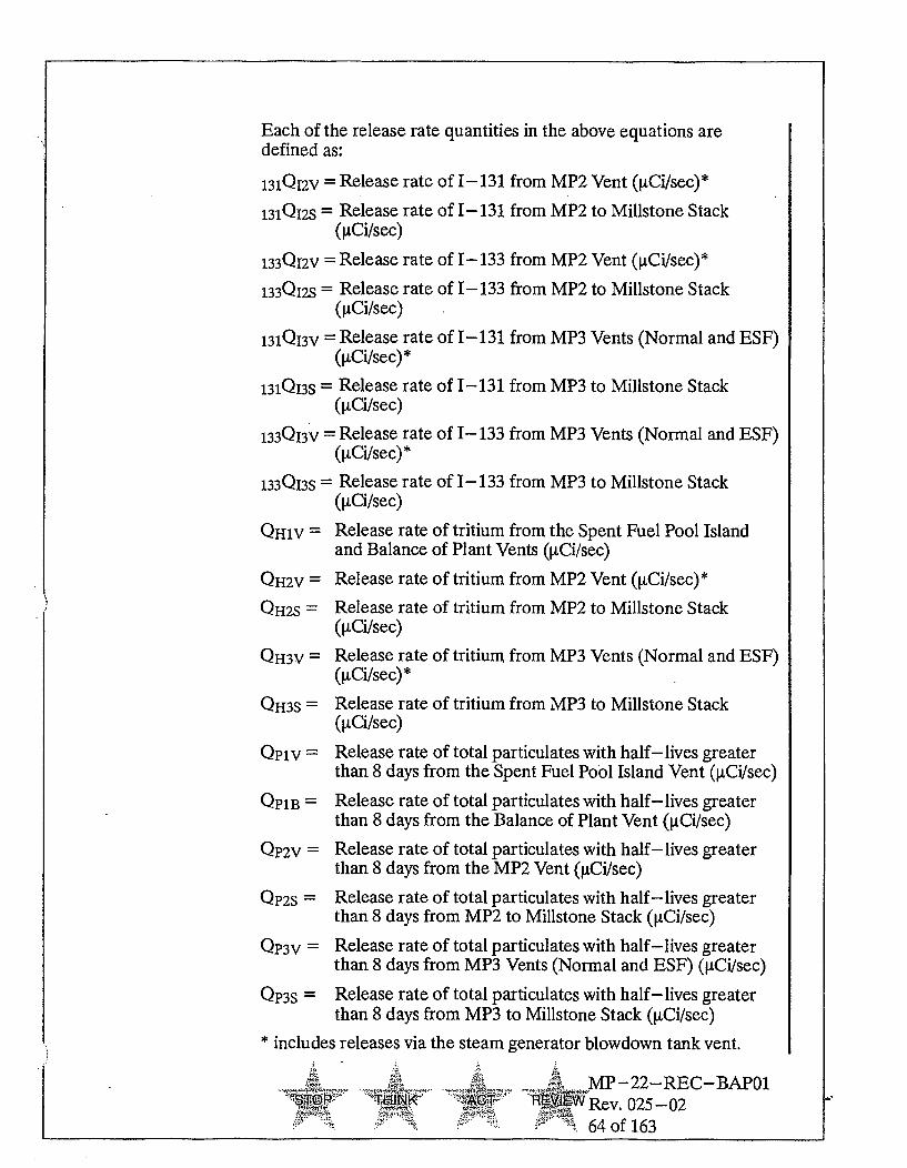
Each of the release rate quantities in the above equations aredefined as:
131Q12V = Release rate of 1-131 from MP2 Vent (RCi/sec)*
131Q12S = Release rate of I- 131 from MP2 to Millstone Stack([LCi/sec)
133Q12V = Release rate of 1-133 from MP2 Vent ([,Ci/sec)*
133Q12S = Release rate of 1-133 from MP2 to Millstone Stack([tCi/sec)
131Q13V - Release rate of 1-131 from MP3 Vents (Normal and ESF)([tCi/sec)*
131Q13S = Release rate of 1-131 from MP3 to Millstone Stack([tCi/sec)
133Q13V = Release rate of 1- 133 from MP3 Vents (Normal and ESF)([tCi/sec) *
133Q13S - Release rate of 1-133 from MP3 to Millstone Stack([tCi/sec)
QH1V = Release rate of tritium from the Spent Fuel Pool Islandand Balance of Plant Vents ([LCi/sec)
QH2V = Release rate of tritium from MP2 Vent ([tCi/sec)*
QH2S = Release rate of tritium from MP2 to Millstone Stack([,Ci/sec)
QH3V = Release rate of tritium from MP3 Vents (Normal and ESF)([tCi/sec) *
QH3S = Release rate of tritium from MP3 to Millstone Stack([,Ci/sec)
Qplv = Release rate of total particulates with half-lives greaterthan 8 days from the Spent Fuel Pool Island Vent ([,Ci/sec)
QP1B = Release rate of total particulates with half-lives greaterthan 8 days from the Balance of Plant Vent (VCi/sec)
QP2V = Release rate of total particulates with half-lives greaterthan 8 days from the MP2 Vent (gCi/sec)
QP2S = Release rate of total particulates with half-lives greaterthan 8 days from MP2 to Millstone Stack ([tCi/sec)
QP3V = Release rate of total particulates with half-lives greaterthan 8 days from MP3 Vents (Normal and ESF) ([,Ci/sec)
QP3S = Release rate of total particulates with half-lives greaterthan 8 days from MP3 to Millstone Stack ([LCi/sec)
includes releases via the steam generator blowdown tank vent..AAR MP-22-REC-BAPO1
N•E0' .... 'W Rev. 025-02
0- ... 64 of 163

c. Method 2
The above Method 1 equations assume a conservative nuclide mix. Ifnecessary, utilize the GASPAR, or a code which uses the methodologygiven in Regulatory Guide 1.109, code to estimate the dose rate fromeither noble gases or iodines, tritium, and particulates with half-livesgreater than 8 days. The use of the code is described inMP-22-REC-GDLO4, "Gaseous Dose Calculations - GASPARII."Additional information on GASPAR is contained in theMP-22-REC-REF03, "REMODCM Technical Information Manual."
2. 10 CFR50 Appendix I - Noble Gas Limits
Radiological Effluent Controls (Sections III, IV, and V) limit the off-site airdose from noble gases released in gaseous effluents to 5 mrad gamma and10 mrad beta for a calendar quarter (10 and 20 mrad gamma and beta,respectively, per calendar year). Effluent dose calculations are calculated atleast once every 31 days. In addition, installed portions of the gaseousradwaste treatment system are required to be operated to reduce radioactivematerials in gaseous effluents when the projected doses over 31 days fromthe applicable waste stream exceed 0.02 mrad air gamma or 0.04 mrad airbeta. (See Appendix A, Tables App.A- 1 for a cross reference of effluentcontrol requirements and applicable sections of the REMODCM which areused to determine compliance.) This part of the REMODCM provides thecalculation methodology for determining air doses from noble gases.
a. Method 1 Air Dose* (Applicable to Units 1, 2, and 3)
For Unit 1: DG1 = 3.3 x 10⁻⁶ CN1V*
DB1 = 1.49 x 10- CN1V*
For Unit 2: DG2 = 6.3 x 10⁻⁴ CN2V + 1.81 x 10⁻⁴ CN2S *DB2 = 1.7 x 10⁻³ CN2V + 1.81 x 10⁻⁶ CN2S *
For Unit 3: DG3 = 6.3 x 10⁻⁴ CN3V+ 1.81 x 10- 4 CN3S *
DB3 = 1.7 x 10- 3 CN3V+ 1.81 x 10⁻⁶ CN3S *
If DG1, DG2, or DG3 are greater than 1.6 mrad or DB1, DB2, or DB3 aregreater than 3.3 mrad within a calendar quarter, go to Method 2 below.
Where:
DG1 = the gamma air dose from Unit 1 for the period of interest (mrad).
DB1 = the beta air dose from Unit ifor the period of interest (mrad).
..... . 3 .,MP-22-REC-BAP01T•-91[ Rev. 025-02
65 of 163

DG2 = the gamma air dose from Unit 2 for the period of interest (mrad).
DB2 = the beta air dose from Unit 2 for the period of interest (mrad).
DG3 = the gamma air dose from Unit 3 for the period of interest (mrad).
DB3 = the beta air dose from Unit 3 for the period of interest (mrad).
CN1V= the total curies of noble gas released from Spent Fuel PoolIsland Vent during the period of interest.
CN2V = the total curies of noble gas released from Unit 2 Vent duringthe period of interest. Include containment releases to Unit 2Vent
CN2S = the total curies of noble gas released from Unit 2 to MillstoneStack during the period of interest.
CN3V = the total curies of noble gas released from Unit 3 vents duringthe period of interest. Include containment releases to Unit 3Vent and ESF Building Vent.
CN3S = the total curies of noble gas released from Unit 3 to Millstone
Stack during the period of interest.
* See MP -22- REC-REF03, "REMODCM Technical InformationDocument," Section 4.2, for the derivation of air dose Method 1 factors.
b. Method 2 Air Dose (Applicable to Units 1, 2, and 3)
Use the GASPAR computer code, or a code which uses the methodologygiven in Regulatory Guide 1.109, to determine the critical site boundaryair doses.
For the Special Location, enter the following worst case quarterlyaverage meteorology based on the Unit 2 vent eight-year history for 1980to 1987:
,JQ = 8.1 x 10⁻⁶ sec/m3
D/Q = 1.5 x 10⁻⁷ m-2
(See the MP-22-REC-REF03, (Att) "Determination of MaximumxIQ and D/Q.")
- MP-22-REC-BAPOI:g.P AMA W- ":'Rev. 025-02
- 66 of 163

If the calculated air dose exceeds one half the quarterly RadiologicalEffluent Control limit, use meteorology concurrent with quarter ofrelease.
c. Estimation of Annual Air Dose Limit Due to Noble Gases (Applicableto Units 1, 2, and 3)
An estimation of annual (year-to-date) beta and gamma air doses(DyB and DyG, respectively) from noble gases released from Units 1, 2and 3 shall be made every month to determine compliance with theannual dose limits for each Unit. Annual air doses will be determined asfollows:
Unit 1
DyGI = YDGI
DYBi = IDB1
Unit 2
DYG2 = XDG2
DYB2 = JDB2
Unit 3
DyG3 = YD G 3
DyB3 = YDB3
Where the sums are over the first quarter (i.e., summation of the allrelease periods within the quarter) through the present calendar quarterdoses.
Where: DYG1, DYG2, DYG3, DYB1, DYB2 and DyB3 = gamma air doseand beta air dose for the calendar year for Unit 1, 2, or 3.
The following shall be used as the quarterly doses:
(1) If the detailed quarterly dose calculations required per SectionII.D.5. for the Radioactive Effluent Release Report are complete for anycalendar quarter, use those results.
(2) If the detailed calculations are not complete for a particular quarter,use the results as determined above in Sections II.D.2.a. or II.D.2.b.
If DYG1, YG2 or YG3 are greater than 10 mrad or DyB1, YB2 or YB3 aregreater than 20 mrad and any corresponding quarterly dose was notcalculated using Method 2 (Section II.D.2.b.), recalculate the quarterlydose using meteorology concurrent with quarter of release.
~T~QP TJAJ~1< A~I~.:•MP-22-REC-BAP01
l'J"WRev. 025-0267 of 163

3. 10 CFR50 Appendix I - Iodine, Tritium and Particulate Doses
Radiological Effluent Controls (Section III, IV, and V) limit the off-sitedose to a critical organ from radioiodines, tritium, and particulates withhalf-lives greater than 8 days released in gaseous effluents to 7.5 mrem for acalendar quarter (15 mrem per calendar year). Effluent dose calculationsare performed at least once every 31 days. In addition, installed portions ofthe gaseous radwaste treatment system are required to be operated to reduceradioactive materials in gaseous effluents when the projected doses over31 days from the applicable waste stream exceed 0.03 mrem. (SeeAppendix A, 'Tble App.A- 1 for a cross reference of effluent control I@requirements and applicable sections of the REMODCM which are used todetermine compliance.) This part of the REMODCM provides thecalculation methodology for determining critical organ doses fromatmospheric releases of iodines, tritium and particulates.
a. Critical Organ Doses (Applicable to Millstone Stack and Unit 1
releases)
1) Method 1 - Millstone Stack and Unit 1 Releases
Calculate organ doses for DTS and Dos:
For Unit 2 or 3: DTS = 30 13 1CIs + 0.29133CIs + 4.66 x 10⁻⁵ CHSDOS = 10.2Cps + 4.66 x 10⁻⁵ CHS
Sum critical organ doses from stack with critical organ doses fromvent in Section II.D.3.b.1) below:
If either dose is greater than 2.5 mrem within a calendar quarter goto Method 2a below
For Unit 1: DTS = 1.97 x 10⁻³ CHVDOS = 94.8[Cpv+ CpBI+ 1.97 x 10- 3 CHV
If either dose is greater than 2.5 mrem within a calendar quarter goto Method 2a below
Where:
DTS= the thyroid dose for the period of release of gaseouseffluents.
Dos =the dose to the maximum organ other than the thyroidfor the period of gaseous effluent release.
T1A- K • MP-22--REC-BAP01
Rev. 025-02
68 of 163

131CIS =The total curies of 1-131 released in gaseous effluentsfrom Unit 2 or 3 to Millstone Stack during the period ofinterest.
133CIS = The total curies of 1-133 released-in gaseous effluentsfrom Unit 2 or 3 to Millstone Stack during the period ofinterest.
Cps = the total curies of particulates with half-lives greaterthan 8 days released in gaseous effluents from MillstoneStack during the period of interest.
Cpv = the total curies of particulates with half-lives greaterthan 8 days released in gaseous effluents from the SFPIvent during the period of interest.
CPB = the total curies of particulates with half-lives greaterthan 8 days released in gaseous effluents from the BOPvent during the period of interest.
CHS = the total curies of tritium released in gaseous effluentsfrom Millstone Stack during period of interest.
CHV = the total curies of tritium released in gaseous effluentsfrom the SFPI and BOP vents during period of interest.
2) Method 2 - Millstone Stack and Unit 1 Releases
Use the GASPAR code, or a code which uses the methodology givenin Regulatory Guide 1.109, with actual locations, real-timemeteorology and the pathways which actually exist at the time atthose locations:
Sum critical organ doses from stack with critical organ doses fromvent in Section II.D.3.b. below.
b. Critical Organ Doses (Applicable to Units 2 and 3 vent releases)
1) Method 1 - Unit 2 and Unit 3 releases
For Unit 2 and Unit3, separately, calculate organ doses DT and DO:
DTV = 230 131C1v + 4.0 133CIv + 2.6 x 10- 3 CHV
DOV = 1.1 x 10³ CpV + 2.6 x 10⁻³ CHV
Sum with organ doses for releases from the stack fromSection II.D.3.a.1):
DT = DTS + DTVDo = DOS + DOV
Aft;I - . MP-22-REC-BAP01
S... ""TF .... AC~T "---..R•-ev. 025-02
69 of 163

If either dose is greater than 2.5 mrem within a calendar quarter goto Section II.D.3.a. and recalculate any organ dose greater than 2.5mrem for releases from the stack and go to Section II.D.3.b. belowand recalculate any organ dose greater than 2.5 mrem for releasesfrom the vent, where:
DT = the total thyroid dose for the period of gaseous effluentsreleases.
Do = the total dose to the maximum organ other than thethyroid for the period of gaseous effluent releases.
DTV = the thyroid dose for the period of gaseous effluentsreleases from the vent.
Dov= the dose to the maximum organ other than the thyroidfor the period of gaseous effluent releases from thevent.
131CIv= The total curies of 1-131 in gaseous effluents fromUnit 2 other than to the Millstone Stack (Unit 2 Vent,containment releases to vent, and Steam GeneratorBlowdown Tank Vent) or from Unit 3 other than to theMillstone Stack (Unit 3 Vent, ESF Building Vent,containment releases to vent, Steam GeneratorBlowdown Tank Vent, and Containment Drawdownusing the hogger) during the period of interest.
133CIV=The total curies of 1-133 in gaseous effluents fromUnit 2 other than to the Millstone Stack (Unit 2 Vent,containment releases to vent, and Steam GeneratorBlowdown Thnk Vent) or from Unit 3 other than to theMillstone Stack (Unit 3 Vent, ESF Building Vent,containment releases to vent, Steam GeneratorBlowdown Thnk Vent, and Containment Drawdownusing the hogger) during the period of interest.
Cps= The total curies of particulates with half-lives greaterthan eight days released in gaseous effluents fromUnit 2 other than to the Millstone Stack (Unit 2 Ventand containment releases to vent) or from Unit 3 otherthan to the Millstone Stack (Unit 3 Vent, ESF BuildingVent, containment releases to vent, and ContainmentDrawdown using the hogger) during the period ofinterest.
q . MP-22-REC-BAPO1-R ev. 025-02
70 of 163

2)
CHV = The total curies of tritium released in gaseous effluentsfrom Unit 2 other than to the Millstone Stack (Unit 2Vent, Steam Generator Blowdown Tank Vent andcontainment releases to vent) or from Unit 3 other thanto the Millstone Stack (Unit 3 Vent, ESF Building Vent,Steam Generator Blowdown Tank Vent containmentreleases to vent, and Containment Drawdown using thehogger) during the period of interest.
Method 2 - Unit 2 and Unit 3 releases
Use the GASPAR code, or a code which uses the methodology givenin Regulatory Guide 1.109, with the actual locations, real-timemeteorology and the pathways which actually exist at the time atthese locations. For Unit 2, the code shall be run separately forsteam generator blowdown tank vents and ventilation releases,containment purges and waste gas tank releases. For Unit 3, thecode shall be run separately for ventilation, process gas, containmentvacuum system, ESF ventilation and containment purges.
fial.MP -22-REC-BAP01SP fý7%0f`J A tE7R ev. 025-0271 of 163

c. Estimation of Annual Critical Organ Doses Due to Iodines, Tritium andParticulates (Applicable to Units 1, 2, and 3)
An estimation of annual (year-to-date) critical organ doses (DyT andDyo for thyroid and maximum organ other than thyroid, respectively)from radioiodine, tritium and particulates with half-lives greater than 8days released from Units 1, 2 and 3 shall be made every month todetermine compliance with the annual dose limits for each Unit. Annualcritical organ doses will be determined as follows:
Unit 1 Unit 2 Unit 3DyT1 = FDT1 DYG2 = -DT2 DYT3 = IDT3DyoI = ID 0 1 Dy02 = YD 0 2 Dy0 3 = YDo3
Where the sums are over the first quarter (i.e., summation of the allrelease periods within the quarter) through the present calendar quarterdoses.
Where:
DyT1, DyT2, DYT3, Dy0 1, Dy02 and Dy0 3 = thyroid (T) dose andmaximum organ (0) dose (other than the thyroid) for the calendar yearfor Unit 1, 2, or 3.
The following guidelines shall be used for DT and DO:
(1) If the detailed quarterly dose calculations required perSection II.D.5. for the Radioactive Effluent Release Report arecomplete for any calendar quarter, use those results.
(2) If the detailed calculations are not complete for a particular quarter,use the results as determined above in Section II.D.3.a. or II.D.3.b.
(3) If DyT and/or DyO are greater than 15 mrem and quarterly dose wasnot calculated using Method 2 of Section II.D.3.a. or II.D.3.b., ICrecalculate the quarterly dose using Method 2.
(4) If different organs are the maximum organ for different quarters,they can be summed together and Dyo recorded as a less-thanvalue as long as the value is less than 15 mrem. If it is not, the sumfor each organ involved shall be determined.
....... z•*• _MP-22-REC-BAP01S-3' Rev. 025-02
, ' 72 of 163

4. Gaseous Effluent Monthly Dose Projections
Section I.D.2.a. of the REMM requires that certain portions of the gaseousradwaste treatment equipment be .returned to service to reduce radioactivegaseous effluents when the projected doses for each Unit (made at least onceper 31 days) exceed 0.02 mrad gamma air, 0.04 mrad beta air, or 0.03 mremto any organ from gaseous effluents. The following methods are applied inthe estimation of monthly dose projections.
a. Unit 1 Projection Method
None required.
b. Unit 2 Projection Method
1) Due to Gaseous Radwaste 'Treatment System (Unit 2)
Determine the beta and gamma monthly air dose projection fromnoble gases from the following:
DEMG (mrad) = 1.81 x 10⁻⁴ CEN
DEMB (mrad) = 1.81 x 10⁻⁶ CEN
Where:
CEN = the number of curies of noble gas estimated to bereleased from the waste gas storage tanks during thenext-month.
DEMG = the estimated monthly gamma air dose.
DEMB = the estimated monthly beta air dose.
(The dose conversion factor is from MP-22-REC-REF03,"REMODCM Technical Information Document," Section 4.2, forthe Millstone Stack releases since the Unit 2 waste gas tanks aredischarged via the Millstone Stack. This factor is conservativebecause the isotopic mix assumed for the dose conversion factorconsists of shorter-lived noble gases which have higher doseconversion factors than the typical mix from Unit 2 waste gas tankdischarges.)
2) (Reserved)
3) Due to Ventilation Releases (Unit 2)
R. .MP-22-REC-BAP01TP TiN Rev. 025-02
- 73 of 163

If portions of the ventilation treatment system are expected to be outof service during the month, determine the monthly maximum organdose projection (DEMO ) from the following:
Method 1
Determine DEMO which is the estimated monthly dose to themaximum organ from the following:
DEMO = 1/3 R1 (1.01- R2) (R3+ 0.01) Do
For the last quarter of operation, determine Do as determinedper Section II.D.3.b.
R1 = the expected reduction factor for the HEPA filter.Typically this should be 100 (see NUREG-0016 or0017 for additional guidance).
R2 = the fraction of the time which the equipment wasinoperable during the last quarter.
R3 = the fraction of the time which the equipment isexpected to be inoperable during the next month.
ii. Method 2
If necessary, estimate the curies expected to be released for thenext month and applicable method for dose calculation fromSection II.D.3.b.
4-
~PHNl( ACT~MP-22-REC-BAP01
REVM5W Rev. 025-0274 of 163

c. Unit 3 Projection Method
1) Due to Radioactive Gaseous Waste System (Unit 3)
Determine the beta and gamma monthly air dose projection fromnoble gases from the following:
DEMO (mrad) = 1.81 x i0. 4 CEN
DEMB (mrad) = 1.81 x 10⁻⁶ CEN
Where:CEN --- the number of curies of noble gas estimated to be
released from the reactor plant gaseous vents(the activity from this pathway increases when theprocess waste gas system is out of service.) duringthe next month.
DEMO =the estimated monthly gamma air dose.
DEMB ---the estimated monthly beta air dose.
(The dose conversion factor is from the MP-22--REC-REF03,"REMODCM Technical Information Document," for theMillstone Stack releases since the Unit 3 reactor plant gaseousvents are discharged via the Millstone Stack.)
2) Due to Steam Generator Blowdown Tank Vent (Unit 3)
Method 1
Determine DEMo which is the estimated monthly dose to themaximum organ:
DEMo = 1/3 Rlx DT
For the last quarter of operation, determine DT as determinedper Section II.D.3.b.
Where:R1 = the expected ratio of secondary coolant iodine level
for the coming month as compared with the averagelevel during the quarter used in the determining Dabove.
ii. Method 2
If necessary, estimate the curies expected to be released for thenext month and applicable method for dose calculation fromSection II.D.3.b.
AI ..... MP-22--REC-BAP01..... NI( •: RE.IEWRev. 025-02
• -- •" • : , '÷ 75 of 163

3) Due to Ventilation Releases (Unit 3)**
If portions of the ventilation treatment system are expected tobe out of service during the month, determine the monthlymaximum organ dose projection (DEMo) from the following:
i. Method 1
Determine DEMO which is the estimated monthly dose to themaximum organ.
DEMO = 1/3 R1 (1.01- R2) (R3 + 0.01) Do
For the last quarter of operation, determine Do as determinedper Section II.D.3.b.
Where:
R1 = the expected reduction factor for the HEPA filter.Typically this should be 100 (see NUREG-0016 or0017 for additional guidance).
R2 = the fraction of the time which the equipment wasinoperable during the last quarter.
R3 = the fraction of the time which the equipment isestimated to be inoperable during the next month.
ii. Method 2
If necessary, estimate the curies expected to be released for thenext month and applicable method for dose calculation fromSection II.D.3.b.
**Since dose projections are only required if the treatment specified
in Section I.D. of the Radiological Effluent Monitoring Manual arenot operating, the monthly gamma and beta air dose projections arenot required for ventilation releases.
5. Quarterly Dose Calculations for Radioactive Effluent Release Report
Detailed quarterly gaseous dose calculations required for the RadioactiveEffluent Release Report shall be done using the computer code GASPAR, ora code which use the methodology given in Regulatory Guide 1.109.
- MP-22-REC-BAP01
ST- '.- MA " Rev 025-02
-0. - -76 of 163

6. Compliance with 40CFR190
The following sources shall be considered in determining the total dose to areal individual from uranium fuel cycle sources:
a. Gaseous Releases from Units 1, 2, and 3.
b. Liquid Releases from Units 1, 2, and 3.
c. Direct and Scattered Radiation from Radioactive Material on Site.
d. Since all other uranium fuel cycle sources are greater than 5 miles away,they need not be considered.
The Radiological Effluent Controls in Sections III.E. (Unit 1), IVE. (Unit2), and VE. (Unit 3) contain specific requirements for ensuring compliancewith 40CFR190 based on gaseous and liquid doses (sources a and b).
Doses to source c are controlled by design and operations to ensure theoff-site dose from each radwaste storage facility is less than one mrem peryear. Potential doses from each facility are evaluated in RadiologicalEnvironmental Reviews (RERs) where total off-site doses from all sourcesare considered to ensure compliance with 40CFR190.
7. Bases for Gaseous Pathway Dose Calculations
The dose calculation methodology and parameters used in Section II of theREMODCM implement the requirements in Section III.A. of Appendix I(10CFR50) which states that conformance with the ALARA dose objectivesof Appendix I be shown by calculational procedures based on models anddata, such that the actual exposure of a member of the public throughappropriate pathways is unlikely to be substantially underestimated.Operational flexibility is provided by controlling the instantaneous releaserate of noble gas (as well as iodines and particulate activity) such themaximum off-site dose rates are less than the equivalent of 500 mrem/yearto the whole body, 3000 mrem/year to the skin from noble gases, or 1500mrem/year to a critical organ from the inhalation of iodines, tritium andparticulates. The dose rate limits are based on the 10CFR20 annual doselimits, but applied as an instantaneous limit to assure that the actual doseover a year will be well below these numbers.
The equivalent instantaneous release rate limits for Millstone Stack weredetermined using the EPA AIREM code. For Units 2 & 3, these doses werecalculated using the NRC GASPAR code. The AIREM code calculatescloud gamma doses using dose tables from a model that considers the finiteextent of the cloud in the vertical direction. Beta doses are calculatedassuming semi- infinite cloud concentrations, which are based upon a
'jQP _••. MP-22--REC-BAPO1- .... INK .. Rev. 025-02
0 - 77 of 163

standard sector averaged diffusion equation. The GASPAR code implementsthe models of NRC Regulatory Guide 1.109, Rev. 1, "Calculation of AnnualDoses to Man from Routine Releases of Reactor Effluents for the Purpose ofEvaluating Compliance with 10CFR Part 50, Appendix I." Input parametervalues typically used in the dose models are listed in MP-22-REC-REF03,"REMODCM Technical Information Document." This same methodology isused in the determination of compliance with the 40CFR190 total dosestandard for the gaseous pathways.
In the determination of compliance with the dose and dose rate limits,maximum individual dose calculations are performed at the nearest land siteboundary with maximum decayed X/Q, and at the nearest vegetable garden(assumed to be nearest residence) and cow and goat farms with maximumD/Qs. The conversion constants in the Method 1 equations for maximum airdoses, organ and whole body doses, and dose rates are based on themaximum observed comparison of historical effluent releases andcorresponding calculated maximum doses. The dose conversion factors arecalculated based on the ratio of the observed highest dose and the curies offission and activation products released during the period. This ratio resultsin the Method 1 equation conversion factor in mrem/Ci released.
MP-22-REC-REF02 describes the derivation of the Method 1 constantsand list the historical maximum doses calculated for the maximum organ.
RE• MP-22-REC-BAPO1•#Rev. 025 -02
78 of 163

II.E. Liquid Discharge Flow Rates And Monitor Setpoints
1. Unit 1 Reactor Cavity Water Discharge Line
The limit on discharge flow rate and setpoint on the Unit 1 liquid wastemonitor depend on dilution water flow, radwaste discharge flow, the isotopiccomposition of the liquid, the background count rate of the monitor and theefficiency of the monitor. Due to the variability of these parameters, thealert and alarm setpoints will be determined prior to the release of eachbatch. The following method will be used:
STEP 1:
From the isotopic analysis and the Effluent Concentration (EC) values foreach identified nuclide determine the required reduction factor, i.e.:
R = Required Reduction Factor = ci,of nuclide i
1•- E10 of-nudie i
STEP 2:
Determine the allowable discharge flow (F)
F= 0.1xRxD
Where:
D = The existing dilution flow which is the any dilution flow fromMillstone Unit 2 and/or Unit 3 not being credited for any otherradioactivity discharge during discharge of Unit 1 water.
0.1 = safety factor to limit discharge concentration to 10% of the
Radiological Effluent Control Limit.
STEP 3:
Calculate the monitor setpoint as follows:
Rset = 2xACxRCF
Where:
Rset = The setpoint of the monitor.
AC = The total radwaste effluent concentration ([tCi/ml ) in the tank.
VTQ ~ Ifik .ACT• •
MP-22-REC-BAPO1
SRev. 025- -0279 of 163

RCF = The response correction factor for the effluent line monitorusing the current calibration factor or isotopic-specificresponses.
2 = 'Iblerance limit which brings the setpoint at twice the expectedresponse of the monitor based on sample analysis. With thesafety factor of 0.1 the setpoint would be at 20% of theRadiological Effluent Control Limit.
Option setpoint:
A setpoint based upon worst case conditions may be used. Assume themaximum possible discharge flow, a minimum dilution flow not to exceed100,000 gpm, and a limit of 1 x 10⁻⁷ ItCi/ml which is lower than any 10CFR20EC limit except for transuranics. This will assure that low level releases arenot terminated due to small fluctuations in activity. When using this optionsetpoint independent verification of discharge lineup shall be performed.The optional setpoint may be adjusted (increased or decreased) by factors toaccount for the actual discharge flow and actual dilution flow; however,controls shall be established to ensure that the allowable discharge flow isnot exceeded and the dilution flow is maintained.
2. Reserved
3. Unit 2 Clean Liquid Radwaste Effluent Line - RM9049 and Aerated LiquidRadwaste Effluent Line - RM9116
The setpoint on the Unit 2 clean and aerated liquid waste effluent linesdepend on dilution water flow, radwaste discharge flow, the isotopiccomposition of the liquid, the background count rate of the monitor and theefficiency of the monitor. Due to the variability of these parameters, analarm/trip setpoint will be determined prior to the release of each batch.The following method will be used:
S . MP-22-REC-BAP01STOP -hIINV( ACY ) Rev. 025-02
80 of 163
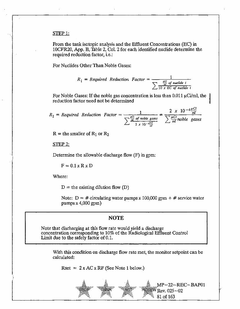
STEP 1:
From the tank isotopic analysis and the Effluent Concentrations (EC) in10CFR20, App. B, .Table 2, Col. 2 for each identified nuclide determine therequired reduction factor, i.e.:
For Nuclides Other Than Noble Gases:
R= Required Reduction Factor = CiMI-of nuclideti •
/,10 x'EC of nudcide i
For Noble Gases: If the noble gas concentration is less than 0.011 •tCi/ml, the Ireduction factor need not be determined
R2= Required Reduction Factor = 1 n =Sciof noble gases
Z 2 x 10-ml
R = the smaller of R1 or R2
STEP 2:
Determine the allowable discharge flow (F) in gpm:
2 x 10⁻⁴-"C
SLcn/noble gases
F = 0.1xRxD
Where:
D = the existing dilution flow (D)
Note: D = # circulating water pumps x 100,000 gpm + # service waterpumps x 4,000 gpm)
NOTE
Note that discharging at this flow rate would yield a dischargeconcentration corresponding to 10% of the Radiological Effluent ControlLimit due to the safety factor of 0.1.
With this condition on discharge flow rate met, the monitor setpoint can becalculated:
Rset 2 x AC x RF (See Note 1 below.)
.. MP-22-REC-BAP01-- _ 4W T-kI > RWWRev. 025-02-.81 of 163

Where:
Rset the setpoint of the monitor (cpm).
AC = the total radwaste effluent concentration ([iCi/ml) in the tank.
RF = the response factor for the effluent line monitor using the currentcalibration factor or isotopic-specific responses.
2 = the multiple of expected count rate on the monitor based on theradioactivity concentration in the tank.
This value or that corresponding to 2.8 x 10⁻⁵ [tCi/ml (Note 2 below),whichever is greater, plus background is the trip setpoint. For the lattersetpoint, independent valve verification shall be performed and minimumdilution flow in Note 2 shall be verified and if necessary, appropriatelyadjusted.
Note 1: If discharging at the allowable discharge rate (F) as determined inabove, this setpoint would correspond to 20% of the RadiologicalEffluent Control limit.
Note 2: This value is based upon worst case conditions, assuming maximumdischarge flow (350 gpm), dilution water flow of 100,000 gpm and alimit of 1 x 10⁻⁷ which is lower than any Technical Specification limit(ten times 10CFR20 EC values) except for transuranics. This willassure that low level releases are not-terminated due to smallfluctuations in activity. However, to verify that the correct tank isbeing discharged when using this value, independent valveverification shall be performed. This value may be adjusted(increased or decreased) by factors to account for the actualdischarge flow and actual dilution flow; however, controls shall beestablished to ensure that the allowable discharge flow is notexceeded and the dilution flow is maintained.
4. Condensate Polishing Facility Waste Neutralization Sump Effluent Line -CND245
When the grab sample prior to release required by Table I.C. -2 is greaterthan 5 x 10⁻⁷ gCi/ml, the setpoint shall be determined as for the Clean andAerated Liquid Monitors in Section II.E.3. except the CPF monitor has thecapability to readout in CPM or [tCi/ml. If the grab sample is less than5 x 10-7 RCi/ml, use a setpoint of the lower of ten times background or thevalue as specified in II.E.3. A setpoint based on ten times background shallnot exceed a reading corresponding to 1.7 x 10⁻⁴ [tCi/ml, which isapproximately 38,000 CPM based on recent calibration data.
MP-22-REC-BAPO1
..s. T V.Rev. 025-02
-- 82 of 163

5. Unit 2 Steam Generator Blowdown - RM4262 and Unit 2 Steam GeneratorBlowdown Effluent Concentration Limitation
5a. Unit 2 Steam Generator Blowdown - RM4262
Assumptions used in determining the Alarm setpoint for this monitorare:
a. Total S.G. blowdown flow rate = 700 gpm.
b. Normal minimum possible circulating water dilution flow duringperiods of blowdown = 200,000 gpm (2 circulating water pumps) =
200,000 gpm.
c. The release rate limit is conservatively set at 3 x 10⁻⁸ [LCi/ml which islower than any 10CFR20 Effluent Concentration (EC) limit exceptfor some transuranics *
d. Background can be added after above calculations are performed.
Therefore, the alarm setpoint corresponds to a concentration of:
Alarm (tuCi/ml) -2000-700 x 3x10 8 + background**= 8.5x10- 6 ACi/ml + background
The latest monitor calibration curve shall be used to determine thealarm setpoint in cpm corresponding to 8.5 x 10⁻⁶ •tCi/ml.
This setpoint may be adjusted (increased or decreased) through properadministrative controls if the steam generator blowdown rate ismaintained other than 700 gpm and/or other than 2 circulating waterpumps are available. The adjustment would correspond to the ratio offlows to those assumed above or:
circulating & service water flow (gpm)Alarm (tzCi/ml) = S.5xlO-',uCi/mI x Ifnrul nt 700 +SIG/GIowdow. (gpm)I-V9V
Background = 3x10 8,uCi/ml x circulating & service water flow (gpm) + Backgroundtotal S/G blowdown (gpm)
THINK AOV.. MP-22-REC-BAP01
REW Rev. 025-02, 83 of 163

NOTE
The Steam Generator Blowdown alarm criteria is in practice based onsetpoints required to detect allowable levels of primary to secondaryleakage. This alarm criteria is typically more restrictive than that requiredto meet discharge limits. This fact shall be verified, however, whenever thealarm setpoint is recalculated.
*In lieu of using 3 x 10⁻⁸ p.Ci/ml, the identified EC limits from 10CFR20
may be used.
**Background of monitor at monitor location (i.e., indication providedby system monitor with no activity present in the monitored system).
5b. Unit 2 Steam Generator Blowdown Effluent Concentration Limitation
The results of analysis of blowdown samples required by Table I.C.-2 ofSection I of the REMODCM shall be used to ensure that blowdowneffluent releases do not exceed ten times the concentration limits in10CFR20, Appendix B.
6. Unit 2 Condenser Air Ejector - RM5099
N/A since this monitor is no longer a final liquid effluent monitor.
7. Unit 2 Reactor Building Closed Cooling Water RM6038 and Unit 2 ServiceWater, and RBCCW Sump and Turbine Building Sump EffluentConcentration Limitation
7a. Unit 2 Reactor Building Closed Cooling Water RM6038
The purpose of the Reactor Building Closed Cooling Water (RBCCW)radiation monitor is to give warning of abnormal radioactivity in theRBCCW system and to prevent releases to the Service Water systemwhich, upon release to the environment, would exceed ten times theconcentration values in 10CFR20. According to CalculationRERM -02665- R2, radioactivity in RBCCW water which causes amonitor response of greater than the setpoint prescribed below couldexceed ten times thel0CFR20 concentrations upon release to the ServiceWater system.
SETPOINT DURING POWER OPERATIONS:
To give adequate warning of abnormal radioactivity, the setpoint shall betwo times the radiation monitor background reading, provided that the
-. _ MP-22-REC-BAP01R Mev. 025-0284 of 163

background reading does not exceed 2,000 cpm. The monitorbackground reading shall be the normal monitor reading. If the monitorbackground reading exceeds 2,000 cpm, the setpoint shall be set at thebackground reading plus 2,000 cpm and provisions shall be made toadjust the setpoint if the background decreases.
SETPOINT DURING SHUTDOWN:
1) During outages not exceeding three months the setpoint shall be twotimes the radiation monitor background reading, provided that thebackground reading does not exceed 415 cpm. If the monitorbackground reading exceeds 415 cpm, the setpoint shall be set at thebackground reading plus 415 cpm and provisions shall be made toadjust the setpoint if the background decreases.
2) During extended outages exceeding three months, but not exceedingthree years, the setpoint shall be two times the radiation monitorbackground reading, provided that the background reading does notexceed 80 cpm. If the monitor background reading exceeds 80 cpm,the setpoint shall be set at the background reading plus 80 cpm andprovisions shall be made to adjust the setpoint if the backgrounddecreases.
PROVISIONS FOR ALTERNATE DILUTION FLOWS:
These setpoints are based on a dilution flow of 4,000 gpm from oneservice water train. If additional dilution flow is credited, the setpointmay be adjusted proportionately. For example, the addition of acirculating water pump dilution flow of 100,000 gpm would allow thesetpoint to be increased by a factor of 25.
7b. Unit 2 Service Water, and RBCCW Sump and Turbine Building SumpEffluent Concentration Limitation
Results of analyses of service water, RBCCW sump and turbine buildingsump samples taken in accordance with Table I.C.-2 of Section I of theREMODCM shall be used to limit radioactivity concentrations in theservice water, RBCCW sump and turbine building sump effluents to lessthan ten times the limits in 10CFR20, Appendix B.
• iM MP-22-REC-BAP01
.... Room Rev. 025-02-.-3 -85 of 163

8. Unit 3 Liquid Waste Monitor - LWS-RE70
The setpoints on the Unit 3 liquid waste monitor depend on dilution waterflow, radwaste discharge flow, the isotopic composition of the liquid, thebackground count rate of the monitor and the efficiency of the monitor. Dueto the- variability of these parameters, the alert and alarm setpoints will bedetermined prior to the release of each batch. The following method will beused:
Step 1:
From the tank isotopic analysis and the Effluent Concentration (EC) valuesfor each identified nuclide determine the required reduction factor, i.e.:
For Nuclides Other Than Noble Gases:
R1 = Required Reduction Factor = 1
of nucldde
10 x"EC of nucide i
For Noble Gases: If the noble gas concentration is less than 0.026 [tCi/ml, thereduction factor need not be determined I
R2= Required Reduction Factor = •,tof noble gases
2 x 1nil
R the smaller of R1 or R2
Step 2:
Determine the allowable discharge flow (F)
2 x 10⁻⁴-u
i noble gases
F = 0.1 xRxD
Where:
D = The existing dilution flow (D):
Note: D = # circulating water pumps x 100,000 gpm+ # service waterpumps x 15,000 gpm
STQ~ THJ~JKACTi!k MP-22-REC--BAP01
.... •iN Rev. 025-02
- 86 of 163

NOTE
Note that discharging at this flow rate would yield a dischargeconcentration corresponding to 10% of the Radiological Effluent ControlLimit due to the safety factor of 0.1.
With this condition on discharge flow rate met, the monitor setpoint can be
calculated:
Rset = 2 x AC x RCF (see Note 1)
Where:
Rset= The setpoint of the monitor.
AC= The total radwaste effluent concentration ([tCi/ml ) in the tank.
RCF= The response correction factor for the effluent line monitor usingthe current calibration factor or isotopic-specific responses.
2 = The multiple of expected count rate on the monitor based on theradioactivity concentration in the tank.
This value, or that corresponding to 6.6 x 10⁻⁵ [tCi/ml (Note 2 below),whichever is greater, plus background is the trip setpoint. For the lattersetpoint, independent valve verification shall be performed and minimumdilution flow in Note 2 shall be verified and if necessary, appropriatelyadjusted.
I
SWP UI'IA .MP-22-REC-BAP01
•REVL~~WRev 025-02
. 87of 163

NOTE
1. If discharging at the allowable discharge rate (F) as determined above,this Alarm setpoint would yield a discharge concentrationcorresponding to 20% of the Radiological Effluent Control limit.
2. This value is based upon worst case conditions, assuming maximumdischarge flow (150 gpm), dilution water flow of 100,000 gpm, and alimit of 1 x 10⁻⁷ tCi/ml which is lower than any Technical Specificationlimit (ten times 10CFR20 EC values) except for transuranics. This willassure that low level releases are not terminated due to smallfluctuations in activity. However, to verify that the correct tank isbeing discharged when using this value, independent valve verificationshall be performed. This value may be adjusted (increased ordecreased) by factors to account for the actual discharge flow andactual dilution flow; however, controls shall be established to ensurethat the allowable discharge flow is not exceeded and the dilution flowis maintained
9. Unit 3 Regenerant Evaporator Effluent Line - LWC-RE65
The MP3 Regenerant Evaporator has been removed from service with DCRM3-97-041. Therefore a radiation monitor alarm is not needed.
10. Unit 3 Waste Neutralization Sump Effluent Line - CND-RE07
Same as Section II.E.8.
11. Unit 3 Steam Generator Blowdown - SSR-RE08 and Unit 3 SteamGenerator Blowdown Effluent Concentration Limitation
I Ia. Unit 3 Steam Generator Blowdown - SSR-RE08
The alarm setpoint for this monitor assumes:
a. Steam generator blowdown rate of 400 gpm (maximum blowdowntotal including weekly cleaning of generators - per ERC25212-ER-99-0133).
b. The release rate limit is conservatively set at 3 x 10⁻⁸ gCi/ml whichis well below any 1OCFR20 Effluent Concentration except fortransuranics*.
c. Minimum possible circulating and service water dilution flow duringperiods of blowdown = 200,000 gpm (2 circulating water pumps) +30,000 gpm (2 service water pumps) = 230,000 gpm.
S4 < NMP- 22-REC-BAP01
. Tf'11'k AQT R-V~IE Rev. 025-02S88 of 163
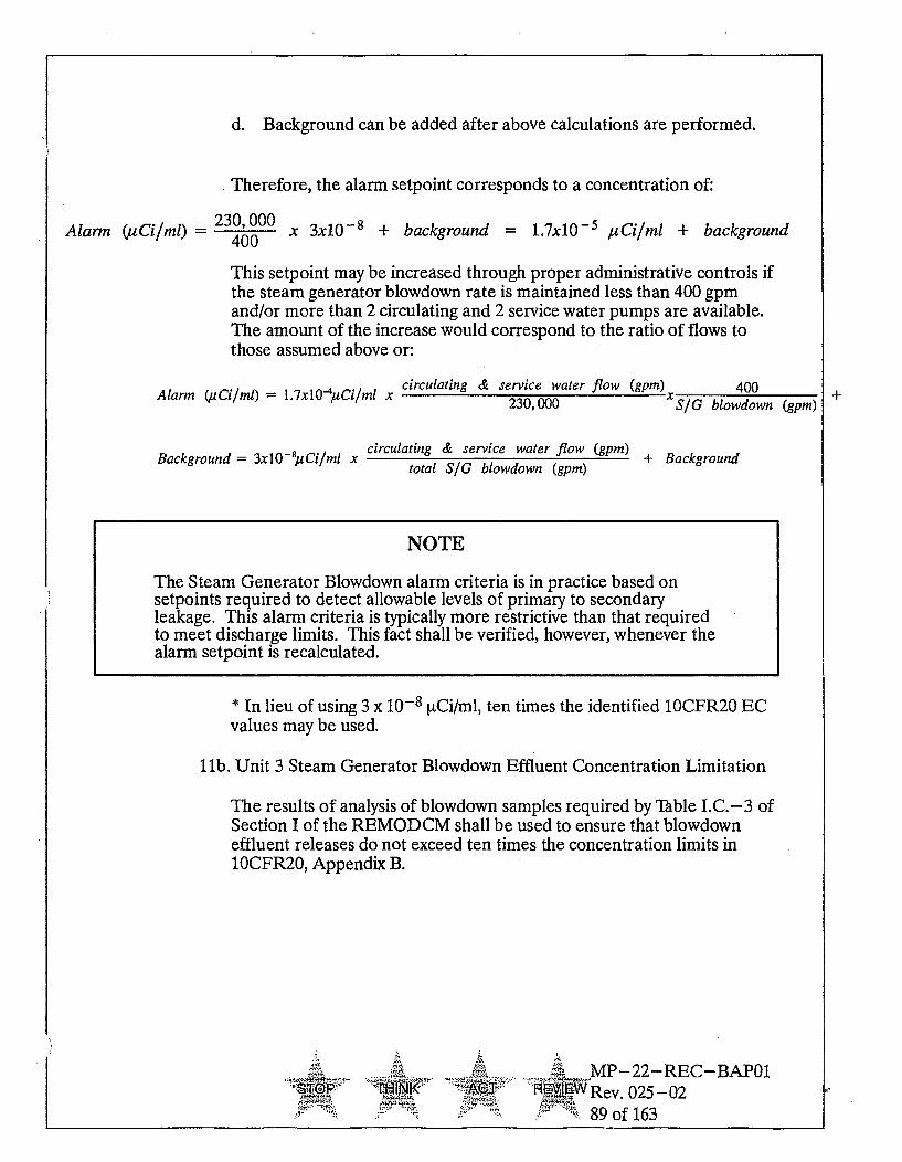
d. Background can be added after above calculations are performed.
Therefore, the alarm setpoint corresponds to a concentration of:
Alarm (uCi4ml) = 230,000 x 3x10- 8 + background = 1.7x10- 5 tCi/ml + background400
This setpoint may be increased through proper administrative controls ifthe steam generator blowdown rate is maintained less than 400 gpmand/or more than 2 circulating and 2 service water pumps are available.The amount of the increase would correspond to the ratio of flows tothose assumed above or:
Alarm(uCi/m) =1.7x10 Ciml x circulating & service water flow (gpm)Alarm (230,000 400
-SIG blowdown (gpm)±
Background = 3xO 8;uCi/ml X circulating & service water flow (gpm) + Background
total SIG blowdown (gpm)
NOTE
The Steam Generator Blowdown alarm criteria is in practice based onsetpoints required to detect allowable levels of primary to secondaryleakage. This alarm criteria is typically more restrictive than that requiredto meet discharge limits. This fact shall be verified, however, whenever thealarm setpoint is recalculated.
* In lieu of using 3 x 10⁻⁸ [tCi/ml, ten times the identified 1OCFR20 ECvalues may be used.
Sl1b. Unit 3 Steam Generator Blowdown Effluent Concentration Limitation
The results of analysis of blowdown samples required by Table I.C.-3 ofSection I of the REMODCM shall be used to ensure that blowdowneffluent releases do not exceed ten times the concentration limits in10CFR20, Appendix B.
4-5M. -MP-22-REC-BAPO1NW Rev. 025 -02
89 of 163

12. Unit 3 Turbine Building Floor Drains Effluent Line - DAS-RE50 and Unit3 Service Water and Turbine Building Sump Effluent ConcentrationLimitation
12a. Unit 3 Turbine Building Floor Drains Effluent Line - DAS-RE50
The alarm setpoint for this monitor shall be set to four times (4X) thereading of the monitor when there is no gamma radioactivity present inthe turbine building sumps. As determined in CalculationRERM-04101R3, the setpoint shall not exceed 1.4 x 10⁻⁵ iiCi/ml.
12b. Unit 3 Service Water and Turbine Building Sump EffluentConcentration Limitation
Results of analyses of service water and turbine building sump samplestaken in accordance with Table I.C.-3 of Section I of the REMODCMshall be used to limit radioactivity concentrations in the service waterand turbine building sump effluents to less than ten times the limits in1OCFR20, Appendix B.
13. Bases for Liquid Monitor Setpoints
Liquid effluent monitors are provided on discharge pathways to control, asapplicable, the release of radioactive materials in liquid effluents duringactual or potential releases of liquid waste to the environment. The alarm /trip setpoints are calculated to ensure that the alarm / trip function of themonitor will occur prior to exceeding ten times the Effluent Concentration(EC) limits of 10 CFR 20 (Appendix B, Table 2, Column 2), which applies tothe release of radioactive materials from all units on the site. This limitationalso provides additional assurance that the levels of radioactive materials inbodies of water in Unrestricted Areas will result in exposures within theSection II.A. design objectives of Appendix I to 10CFR50 to a member of thepublic.
In application, the typical approach is to determine the expectedconcentration in a radioactive release path and set the allowable dischargerate past the monitor such the existing dilution flow will limit the effluentrelease concentration to 10% of the limit for the mix. The setpoint is thenselected to be only 2 times the expected concentration, or 20% of the limit.As a result, considerable margin is included in the selection of the setpointfor the monitor to account for unexpected changes in the dischargeconcentration or the contribution from other potential release pathwaysoccurring at the same time as the planned effluent release. For thosemonitors on systems that are not expected to be contaminated, the alarmpoint is usually selected to be two times the ambient background to givenotice that normal conditions may have changed and should be evaluated.
.4 ;,..,• MP-22-REC--BAP01S• IO- N Rev. 025-02
S90 of 163

ILF. Gaseous Monitor Setpoints
1. Unit 1 Spent Fuel Pool Island Monitor - RM-SFPI-02
The instantaneous release rate limit from the site shall be set in accordancewith the conditions given in Section II.D.1.a. in order to satisfy RadiologicalEffluent Controls III.C.2. and III.D.2.a.
The alarm setpoint shall be set at or below the monitor reading in p[Ci/cccorresponding to 29,000 RCi/sec assuming a maximum ventilation flow of36,000 cfm. The corresponding monitor reading is 1.71E-3 [tCi/cc. NOTE:This setpoint is the basis for emergency classification in Unit 1 EAL Table(OA-1). A change to this setpoint would require a concurrent change to theEAL.
The release rate value of 29,000 pCi/sec assumes that 7% of the site limit forskin dose of 3000 mrem per year is assigned to the Unit 1 Spent Fuel PoolIsland vent. If effluent conditions from the Unit 1 Spent Fuel Pool Islandvent reach 29,000 [tCi/sec, releases from Units 2 and 3 vents and from theMillstone Stack shall be determined to ensure that the sum of the individualnoble gas release rates do not cause the site skin dose limit to be exceeded.Use Section II.D.l.a. and Section 4.2 of MP-22-REC-REF03,"REMODCM Technical Information Document," in making thisdetermination.
2. Unit 2 Wide Range Gas Monitor (WRGM) - RM8169
The instantaneous release rate limit from the site shall be set in accordancewith the conditions given in Section II.D.1.a. in order to satisfy Units 2Radiological Effluent Controls IVC.2. and IVD.2.a.
The alarm setpoint shall be set at or below the monitor reading in ptCi/cccorresponding to 74,000 ptCi/sec assuming a maximum ventilation flow of12,000 cfm. The corresponding monitor reading is 1.31E-2 pACi/cc.
The release rate value of 74,000 [tCi/sec assumes that 13% of the site limit isassigned to Unit 2 releases to the Millstone Stack. If effluent conditionsfrom Unit 2 to the Millstone Stack reach 74,000 ptCi/sec, releases from Units1, 2 and 3 vents and from Unit 3 to the Millstone Stack shall be determinedto ensure that the sum of the individual noble gas release rates do not exceedthe site limit as dictated in Section II.D.l.a., and described inMP-22- REC- REF03, "REMODCM Technical Information Document,"Section 4.2.
3. Reserved
A. MP-22-REC-BAP01.4.P " T R W Rev 025-02
-91 of 163

4. Unit 3 SLCRS - HVR-RE19B
The instantaneous release rate limit from the site shall be set in accordancewith the conditions given in Section II.D.1.a. in order to satisfyUnit 3Radiological Effluent Controls V.C.2. and VD.2.a.
The alarm setpoint shall be set at or below the monitor reading in RCi/cccorresponding to 74,000 [Ci/sec assuming a maximum ventilation flow of12,000 cfm. The corresponding monitor reading is 1.16 E-2 [iCi/cc inaccordance with Calculation RERM-01946R3, Rev.1.
If effluent conditions from Unit 3 to the Millstone Stack reach 74,000[tCi/sec, measures shall be taken to ensure that the sum of the individualnoble gas release rates do not exceed the site limit as dictated in SectionII.D.1.a., and described in MP-22-REC-REF03, "REMODCM TechnicalInformation Document," Section 4.2.
5. Unit 2 Vent - Noble Gas Monitor - RM8132B
The instantaneous release rate limit from the site shall be set in accordancewith the conditions given in Section II.D.1.a. in order to satisfy RadiologicalEffluent Controls in Sections IV.C.2. and IV.D.2.a.
The alarm setpoint shall be set at or below the "cpm" corresponding to95,000 [tCi/sec from the MP2 vent noble gas monitor calibration curve. Thecalibration curve (given as [tCi/sec per cpm) is determined by assuming themaximum possible ventilation flow for various fan combinations. Curves forthree different fan combinations are normally given.
The release rate value of 95,000 [tCi/sec assumes that 33% of the site limit isassigned to the MP2 vent. If effluent conditions from the MP2 vent reach thealarm setpoint, releases from Units 1 and 3 vents and from the MillstoneStack shall be determined to ensure that the sum of the individual noble gasrelease rates do not exceed the site limit as dictated in Section II.D.l.a., anddescribed in MP-22-REC-REF03, "REMODCM Technical InformationDocument," Section 4.2.
6. Unit 2 Waste Gas Decay Tank Monitor RM9095
Administratively all waste gas decay tank releases are via the MillstoneStack. Unit 2 has a release rate limit to the Millstone Stack of 74,000 [tCi/sec(see the MP-22-REC-REF03, "REMODCM Technical InformationDocument," Section 4.2.for bases).
Batch releases of waste gas shall be limited to less than 10% of the Unit 2releases to the Millstone Stack release rate limits. Therefore, the waste gasdecay tank monitor setpoint should be set not to exceed 7,400 [LCi/sec.
.. .. -- -MP-22-REC-BAP01F-- NK A'~A- Rev. 025-02
92 of 163

The MP2 waste gas decay tank monitor (given [tCi/cc per cpm) calibrationcurve and the tank discharge rate is used to assure that the concentration ofgaseous activity being released from a waste gas decay tank does not causethe setpoint of 7,400 RCi/sec to be exceeded.
7. Unit 3 Vent Noble Gas Monitor - HVR- RE10B
The instantaneous release rate limit from the site shall be set in accordancewith the conditions given in Section II.D.L.a. in order to satisfy RadiologicalEffluent Controls in Sections V.C.2. and VD.2.a.
The alarm setpoint shall be set at or below a value of 8.4 x 10- 4 pCi/cc forthe MP3 vent in accordance with Calculation RERM-01946R3, Rev.1.
If effluent conditions from the MP3 vent reach the alarm setpoint, releasesfrom Units 1 and 2 vents and from the Millstone Stack shall be determined toensure that the sum of the individual noble gas release rates do not exceedthe site limit as dictated in Section II.D.l.a., and described inMP-22- REC- REF03, "REMODCM Technical Information Document,"Section 4.2.
8. Unit 3 Engineering Safeguards Building Monitor - HVQ-RE49
The Alarm setpoint shall be set at or below the value of 5.9E-4 p.Ci/cc inaccordance with Calculation RERM-01946-R3, Rev. 0.
9. Bases for Gaseous Monitor Setpoints
Gaseous effluent monitors are provided on atmospheric release pathways tocontrol, as applicable, the release of radioactive materials in gaseouseffluents to the environment. The alarm / trip setpoints are calculated toensure that the alarm / trip function of the monitor will occur prior toexceeding the dose rate limits required by the Technical Specifications (Units2 and 3) or Radiological Effluent Controls (Sections III. IV, and V)requirements for each unit. Monitor setpoint selection is based on aconservative set of conditions for each release pathway (as discussed abovefor each monitor pathway) such that the dose rate at any time at and beyondthe site boundary from all gaseous effluents from all units on the site will bewithin the numerical values of the annual dose limits of 10 CFR 20 inUnrestricted Areas. Since the Radiological Effluent Controls areconstructed such that the numerical values of the annual dose limits of 10CFR 20 be applied on an instantaneous basis (i.e., no time averaging overthe year), and the integrated dose objectives of 10 CFR 50, Appendix Iprovide for corrective actions to reduce effluents if the ALARA dose valuesare exceeded, assurance is obtained that compliance with the revised annualdose limits of 10 CFR 20.1301 (100 mrem total effective dose equivalent to amember of the public) will also be met. The use of the stated instantaneous
6J 5 . .MP-22-REC-BAP01
Or WNK AWRev0 25-02
. 93 of 163

release rate values, which equate to the site dose rate limits, also providesoperational flexibility to accommodate short periods of higher than normaleffluent releases that may occur during plant operations.
APPENDIX Hl•AREMODCM METHODOLOGY CROSS-REFERENCES
Radiological effluent controls (Sections III, IV, and V) identify the requirementsfor monitoring and limiting liquid and gaseous effluents releases from the sitesuch the resulting dose impacts to members of the public are kept to "As Low AsReasonably Achievable" (ALARA). The demonstration of compliance with thedose limits is by calculational models that are implemented by Section II of theREMODCM.
Table App. Il.A- 1 provides a cross- reference guide between liquid and gaseouseffluent release limits and those sections of the REMODCM, which are used todetermine compliance. It also shows the administrative Technical Specificationswhich reference the REMODCM for operation of radioactive waste processingequipment. This table also provides a quick outline of the applicable limits ordose objectives and the required actions if those limits are exceeded. Details ofthe effluent control requirements and the implementing sections of theREMODCM should be reviewed directly for a full explanation of therequirements.
..... v.P-22-REC-BAP01P TH:NK AC. WRev. 025-02
- 94 of 163

Table II.A.-1Millstone Effluent Requirements and Methodology Cross Reference
Radiological REMODCM Applicable Limit or Exposure Required ActionEffluent Controls & Methodology Objective Period
Technical SectionSpecifications I
IV/V.E.1.a Tables I.C.-2 Ten times 10CFR20App.B, Instantaneous Restore concentration to within lim-Liquid Effluent and I.C.-3 Table 2, Column 2, & 2x10- 4 its within 15 mins.Concentration iiCi/mL for dissolved noble
gases*
IV/V.E.I.b II.C.1. -< 1.5 mrem T.B. Calendar Quar- 30-day report if exceeded. RelativeDose-Liquids II.C.2. <5 mrem Organ ter** accuracy or conservatism of the cal-
I.C.3. •53 mrem TB. Calendar Year culations shall be confirmed by per-
II.C.4. -< 10 mrem Organ formance of the REMP in Section 1.
T.S. 6.16 (Unit 2) I.C.2. •__0.06 mrem TB. Projected for 31 Return to operation Liquid WasteTS. 6.14 (Unit 3) II.C.5. <0.2 mrem Organ days (if system Treatment System
Liquid Radwaste Treat- not in use)ment
III.D.2.a Tables I.D.- 1, 5 500 mrem/yr TB. from Instantaneous Restore release rates to within spec-IV/V.D.2.a I.D.-2, & noble gases* ifications within 15 minutes
Gaseous Effluents Dose I.D-3Rate II.D.1.a. _•3000 mrem/yr skin from
noble gases*
II.D.l.b. 5 1500 mrem/yr organ fromparticulates with T1/2 > 8d.,1-131, 1-133 & tritium*
III.D.2.b II.D.2. -55 mrad gamma air Calendar Quar- 30-day report if exceededIV/V.D.2.bDose Noble -. 10 mrad beta air ter**
Gases 510 mrad gamma air Calendar Year
-•20 mrad beta air
III.D.2.c II.D.3. -< 7.5 mnrern organ Calendar Quar- 30-day reportif exceeded. RelativeIVJV.D.2.c ter** accuracy or conservatism of the cal-
Dose 1-131, 1-133, Par- culations shall be confirmed by per-ticulates, H-3 515 mrem organ Calendar Year formance of the REMP in Section i.
T.S. 5.6.4 (Unit 1) II.D.2. >0.02 mrad gamma air Projected for 31 Return to operation Gaseous Rad-T.S. 6.14 (Unit 2) II.D.4. > 0.04 mrad beta air Days (if system waste Treatment SystemT.S 6.16 (Unit 3) >0.03 mrem organ not in use)
Gaseous RadwasteTreatment
IME II.D.6. _ 25 mrem T.B.* 12 Consecutive 30-day report if Unit 1 EffluentIVI /V.F 5 25 mrem organ* Months** Control III.D.1.2, III.D.2.2, or
Total Dose 5 75 mrem thyroid* III.D.2.3 or Units 2/3 Effluent Con-trol IV/V.E.1.2, IV/V.E.2.2, or IV/V.E.2.3 are exceeded by a factor of2. Restore dose to public to withinthe applicable EPA limit(s) or ob-tain a variance
NOTE: TB. means total or whole body.* Applies to the entire site (Units 1, 2, and 3) discharges combined.**Cumulative dose contributions calculated once per 31 days.
.4O TIN1 MP-22-REC-BAP01
E7@f1Vi5WRev 025-02
95 of 163

SECTION III.
Millstone Unit 1
Radiological Effluent Controls
Docket Nos. 50-245
MP-22-REC-BAP01
": - Rev. 025-0296 of 163

SECTION III. REMODCM UNIT ONE CONTROLS
III.A. Introduction
The purpose of this section is to provide the following for Millstone Unit One:
a. the effluent radiation monitor controls and surveillance requirements,
b. the effluent radioactivity concentration and dose controls andsurveillance requirements, and
c. the bases for the controls and surveillance requirements.
Definitions of certain terms are provided as an aid for implementation of thecontrols and requirements.
Some surveillance requirements refer to specific sub-sections in Sections I andII as part of their required actions
III.B. Definitions and Surveillance Requirement (SR) Applicability
1II.13.1 - Definitions
The defined terms of this sub -section appear in capitalized type and areapplicable throughout Section III.
1. ACTION - that part of a Control that prescribes remedial measuresrequired under designated conditions.
2. INSTRUMENT CALIBRATION - the adjustment, as necessary, of theinstrument output such that it responds within the necessary range andaccuracy to know values of the parameter that the instrument monitors. TheINSTRUMENT CALIBRATION shall encompass those components, suchas sensors, displays, and trip functions, required to perform the specifiedsafety function(s). The INSTRUMENT CALIBRATION shall include theINSTRUMENT FUNCTIONAL TEST and may be performed by means ofany series of sequential, overlapping, or total channel steps so that the entirechannel is calibrated.
~ EW Rev. 025 -02Id"- 97 of 163

3. INSTRUMENT FUNCTIONAL TEST - the injection of a simulated oractual signal into the channel as close to the sensor as practicable to verifythat the instrument is OPERABLE, including all components in the channel,such as alarms, interlocks, displays, and trip functions, required to performthe specified safety function(s). For digital instruments, the computerdatabase may be manipulated, in lieu of a signal injection, to verifyoperability of alarm and/or trip functions. The INSTRUMENTFUNCTIONAL TEST may be performed by means of any series ofsequential, overlapping, or total channel steps so that the entire channel istested.
4. INSTRUMENT CHECK - the qualitative determination of operability byobservation of behavior during operation. This determination shall include,where possible, comparison of the instrument with other independentinstruments measuring the same variable.
5. OPERABLE - An instrument shall be OPERABLE when it is capable ofperforming its specified functions(s). Implicit in this definition shall be theassumption that all necessary attendant instrumentation, controls, normaland emergency electrical power sources, cooling or seal water, lubrication orother auxiliary equipment that are required for the instrument to perform itsfunctions(s) are also capable of performing their related support function(s).
6. REAL MEMBER OF THE PUBLIC - an individual, not occupationallyassociated with the Millstone site, who is exposed to existing dose pathwaysat one particular location. This does not include employees of the utility orutilities which own a Millstone plant and utility contractors and vendors.Also excluded are persons who enter the Millstone site to service equipmentor to make deliveries. This does include persons who use portions of theMillstone site for recreational, occupational, or other purposes notassociated with any of the Millstone plants.
7. SITE BOUNDARY - that line beyond which the land is not owned, leased,or otherwise controlled by the licensee.
8. SOURCE CHECK - the qualitative assessment of channel response whenthe channel is exposed to radiation.
9. RADIOACTIVE WASTE TREATMENT SYSTEMS - Radioactive WasteTreatment Systems are those liquid, gaseous, and solid waste systems whichare required to maintain control over radioactive materials in order to meetthe controls set forth in this section.
~ ~ -~ MP-22-REC--BAP0122'r T - Rev. 025-02
98 of 163

III.B.2 - Surveillance Requirement (SR) Applicabilit
1. SRs shall be met during specific conditions in the Applicability for individualLCOs unless otherwise stated in the SR. Failure to meet a Surveillance,whether such failure is experienced during the performance of theSurveillance or between performances of the Surveillance, shall be failure tomeet the LCO. Failure to perform a Surveillance within the specifiedFrequency shall be failure to meet the LCO except as provided in III.B.2 3.Surveillances do not have to be performed on inoperable equipment orvariables outside specified limits.
2. The specified Frequency for each SR is met if the Surveillance is performedwithin 1.25 times the interval specified in the Frequency, as measured fromthe previous performance or as measured from the time a specified conditionof the frequency is met.
3. If it is discovered that a Surveillance was not performed within its specifiedfrequency, then compliance with the requirement to declare the LCO notmet may be delayed from the time of discovery up to 24 hours or up to thelimit of the specified frequency, whichever is less. This delay period ispermitted to allow performance of the surveillance. If the Surveillance is notperformed within the delay period, the LCO must immediately be declarednot met and the applicable Condition(s) must be entered. The CompletionTimes of the Required Actions begin immediately upon expiration of thedelay period. When the Surveillance is performed within the delay periodand the Surveillance is not met, the LCO must immediately be declared notmet and the applicable Condition(s) must be entered. The CompletionTimes of the Required Actions begin immediately upon failure to meet theSurveillance.
_T._.A...., MP-22-REC- BAPO1
WRev. 025-0299 of 163

III.C. Radioactive Effluent Monitoring Instrumentation
1. Radioactive Liquid Effluent Monitoring Instrumentation
CONTROLS
The radioactive liquid effluent monitoring instrumentation channels shownin Table III.C. -1 shall be OPERABLE with applicable alarm/trip setpoints,set to ensure that the limits of Specification III.D.1.a. are not exceeded. Thesetpoints shall be determined in accordance with methods and parametersdescribed in Section II.
APPLICABILITY: As shown in Table III.C. -1
ACTION:
a. With a radioactive liquid effluent monitoring instrumentation channelalarm/trip setpoint less conservative than required by the aboveSpecification, without delay suspend the release of radioactive liquideffluents monitored by the affected channel, or declare the channelinoperable, or change the setpoint so it is acceptably conservative.
b. With the number of channels less than the minimum channelsOPERABLE requirement, take the action shown in Table III.C. -1.Exert best efforts to restore the inoperable monitor to OPERABLEstatus within 30 days and, if unsuccessful, explain in the next RadioactiveEffluent Release Report why the inoperability was not corrected in atimely manner. Releases need not be terminated after 30 days providedthe specified actions are continued.
SURVEILLANCE REOUIREMENTS
Each radioactive liquid effluent monitoring instrumentation channel shall bedemonstrated OPERABLE by performance of the CHANNEL CHECK,SOURCE CHECK, CHANNEL CALIBRATION, and CHANNELFUNCTIONAL TEST operations at the frequencies shown in TableIII.C.-2.
i- I r AT RV.Rev.MP-22-REC-BAP-1
RYiRW Rev. 025 -02100 of 163
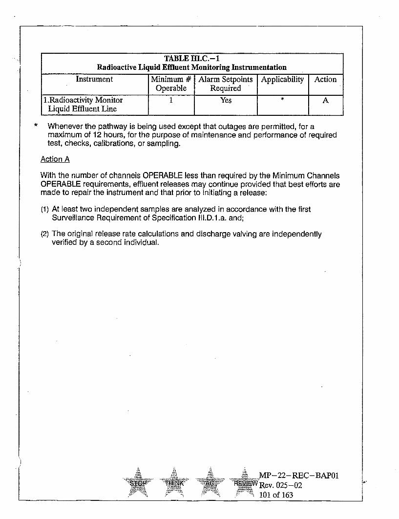
TABLE llI.C.-1Radioactive Liquid Effluent Monitoring Instrumentation
Instrument Minimum # Alarm Setpoints Applicability ActionOperable Required
1.Radioactivity Monitor 1 Yes * A
Liquid Effluent Line
Whenever the pathway is being used except that outages are permitted, for amaximum of 12 hours, for the purpose of maintenance and performance of requiredtest, checks, calibrations, or sampling.
Action A
With the number of channels OPERABLE less than required by the Minimum ChannelsOPERABLE requirements, effluent releases may continue provided that best efforts aremade to repair the instrument and that prior to initiating a release:
(1) At least two independent samples are analyzed in accordance with the firstSurveillance Requirement of Specification II.D.l.a. and;
(2) The original release rate calculations and discharge valving are independentlyverified by a second individual.
.- r , . ,--.--..,.
MP-22-REC-BAP01'RE%-w ev. 025-02
101 of 163
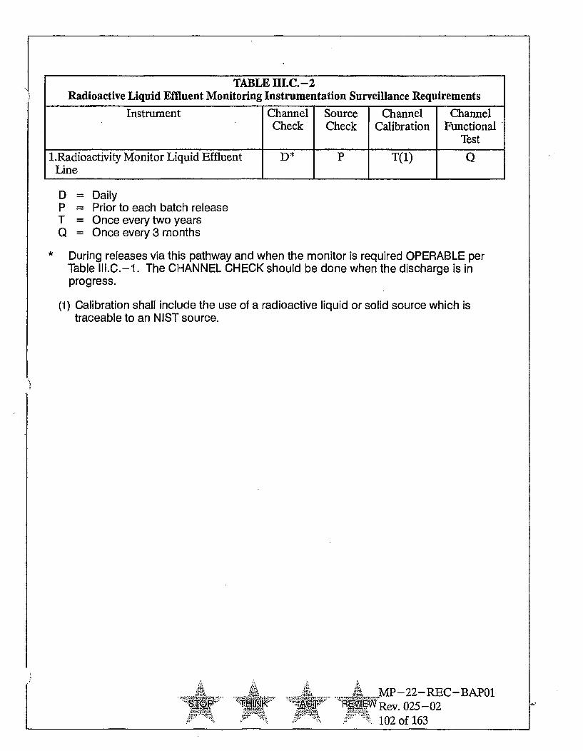
TABLE lI.C.-2Radioactive Liquid Effluent Monitoring Instrumentation Surveillance Requirements
Instrument Channel Source Channel ChannelCheck Check Calibration Functional
Test
1.Radioactivity Monitor Liquid Effluent D* P T(1) QLine
DPTQ
- Daily= Prior to each batch release= Once every two years= Once every 3 months
* During releases via this pathway and when the monitor is required OPERABLE perTable II1.C.-1. The CHANNEL CHECK should be done when the discharge is inprogress.
(1) Calibration shall include the use of a radioactive liquid or solid source which istraceable to an NIST source.
4- -~ ~o
MP-22-REC-BAP01•,.T RERev. 025-02
- . .102 of 163

2. Radioactive Gaseous Effluent Monitoring Instrumentation
CONTROLS
The radioactive gaseous effluent monitoring instrumentation channels shownin Table III.C. -3 shall be OPERABLE with applicable alarm setpoints set toensure that the limits of Control III.D.2.a. are not exceeded. The setpointsshall be determined in accordance with methods and parameters described inSection II.F.1.
APPLICABILITY: As shown in Table III.C.-3
ACTION:
a. With a radioactive gaseous effluent monitoring instrumentation channelalarm setpoint less conservative than required by the above Control,without delay suspend the release of radioactive gaseous effluentsmonitored by the affected channel, or declare the channel inoperable, orchange the setpoint so it is acceptably conservative.
b. With the number of channels less than the minimum channels operablerequirements, take the action shown in Table III.C.-3. Exert bestefforts to restore the inoperable monitor to OPERABLE status within 30days and, if unsuccessful, explain in the next Radiological EffluentRelease Report why the inoperability was not corrected in a timelymanner. Release need not be terminated after 30 days provided thespecified actions are continued.
SURVEILLANCE REOUIREMENT
Each radioactive gaseous effluent monitoring instrumentation channel shallbe demonstrated OPERABLE by performance of the INSTRUMENTCHECK, INSTRUMENT CALIBRATION, INSTRUMENTFUNCTIONAL TEST, and SOURCE CHECK operations at the frequenciesshown in Table III.C.-4.
1-k .MP-22-REC- BAPOI.TOP PP INK" AT WRev. 025-02
103 of 163

TABLE HI.C.-3Radioactive Gaseous Effluent Monitoring Instrumentation
Instrument Minimum Alarm Setpoints Applicability Action# Operable Required
1.Spent Fuel Pool Island Vent
(a) Noble Gas Activity Monitor 1 Yes * A(b) Particulate Sampler 1 No * B(c) Vent Flow Rate Monitor 1 No * C(d) Sampler Flow Rate Monitor 1 Yes * D
2.Balance of Plant Vent(a) Particulate Sampler 1 No * B(b) Sampler Flow Monitor 1 Yes * D
* Channels are OPERABLE and in service on a continuous, uninterrupted basis when exhaustfans are operating, except that outages are permitted, for a maximum of 12 hours, for thepurpose of maintenance and performance of required tests, checks, calibrations, andsampling associated with the instrument or any system or component which affectsfunctioning of the instrument.
ACTION STATEMENTS
Action A
With the number of channels OPERABLE less than required by the Minimum ChannelsOPERABLE requirement, effluent releases via this pathway may continue provided that bestefforts are made to repair the instrument and that grab samples are taken daily when fuel isbeing moved, or during any evolution or event which would threaten fuel integrity, and these Isamples are analyzed for gross activity within 24 hours.
Action B
With the number of samplers OPERABLE less than required by the Minimum numberOPERABLE requirement, effluent releases via this pathway may continue provided that the bestefforts are made to repair the instrument and that a 24 hour sample is collected with auxiliarysampling equipment once every seven (7) days, or anytime significant generation of airborneradioactivity is expected, and analyzed for principal gamma emitters with half lives greater than8 days within 24 hours after the end of the sampling period.
Action C
With the number of channels OPERABLE less than required by the Minimum ChannelsOPERABLE requirement, effluent releases via this pathway may continue provided that bestefforts are made to repair the instrument.
Action D
With the number of channels OPERABLE less than required by the Minimum ChannelsOPERABLE requirement, effluent releases via this pathway may continue provided that bestefforts are made to repair the instrument and that the flow rate is estimated once during theChemistry compensatory sampling time period as specified in Action A or Action B.
ElkP TUK_ ~ MP-22-REC-BAP01MYW Rev. 025-02
'' 104 of 163

[ TABLE IH.C.-4Radioactive Gaseous Effluent Monitoring Instrumentation Surveillance Requirements
Instrument Instrument Instrument Functional SourceCheck Calibration Test Check
1.Spent Fuel Pool Island Vent
(a) Noble Gas Activity Monitor D(3) T(6) Q(7) M
(b) Particulate Sampler TM NA NA NA(c) Vent Flow Rate Monitor D T NA NA
(d) Sampler Flow Rate Monitor D T NA NA2.Balance of Plant Vent
(a) Particulate Sampler TM NA NA NA
(b) Sampler Flow Monitor D T NA NA
D = DailyW = WeeklyTM = Twice per monthM - MonthlyQ = Once every 3 monthsT = Once every two yearsNA= Not Applicable
Table lII.C.-4TABLE NOTATION
(1) RESERVED
(2) RESERVED
(3) Instrument check daily only when there exist releases via this pathway.
(4) RESERVED
(5) RESERVED
(6) Calibration shall include the use of a known source whose strength is determined by adetector which has been calibrated to a source which is traceable to the NIST. Thesesources shall be in a known reproducible geometry.
(7) The INSTRUMENT FUNCTIONAL TEST shall also demonstrate that control roomalarm annunciation occurs if any of the following conditions exist:
1. Instrument indicates measured levels above the alarm/trip setpoint.
2. Instrument indicates a downscale failure.
_ g- • MP-22-REC-BAP01.. W Rev. 025-02
J" "105 of 163

III.D. Radioactive Effluents Concentrations And Dose Limitations
1. Radioactive Liquid Effluents
a. Radioactive Liquid Effluents Concentrations
LIMITING CONDITIONS OF OPERATIONS
The concentration of radioactive material released from the site (seeFigure III.D.- 1) shall not exceed ten times the concentrations specifiedin 10 CFR Part 20, Appendix B, Table 2, Column 2 for radionuclidesother than dissolved or entrained noble gases. For dissolved orentrained noble gases, the concentration shall not exceed 2 x 1 0 -4 [,Ci/mltotal activity.
APPLICABILITY: At all times.
ACTION:
With the concentration of radioactive material released from the siteexceeding the above limits, restore the concentration to within the abovelimits within 15 minutes.
SURVEILLANCE REOUIREMENT
Radioactive liquid wastes shall be sampled and analyzed according to thesampling and analysis program specified in Section I.The results of the radioactive analysis shall be used in accordance withthe methods of Section II to assure that the concentrations at the pointof release are maintained within the limits of Specification III.D.L.a.
-STOP TfIINK
-MP-22-REC-BAP01
ACT REVfIEW Rev. 025-02
106 of 163

b. Radioactive Liquid Effluents Doses
LIMITING CONDITIONS OF OPERATIONS
The dose or dose commitment to any REAL MEMBER OF THEPUBLIC from radioactive materials in liquid effluents from Unit 1released from the site (see Figure III.D. -1) shall be limited:
a. During any calendar quarter to less than or equal to 1.5 mrem to thetotal body and to less than or equal to 5 mrem to any organ; and,
b. During any calendar year to less than or equal to 3 mrem to the totalbody and to less than or equal to 10 mrem to any organ.
APPLICABILITY: At all times
ACTION:
a. With the calculated dose from the release of radioactive materials inliquid effluents exceeding any of the above limits prepare and submitto the Commission within 30 days a Special Report which identifiesthe cause(s) for exceeding the limit(s) and defines the correctiveactions to be taken to reduce the releases of radioactive materials inliquid effluents during the remainder of the current calendar quarterand the calendar year so that the cumulative dose or dosecommitment to any REAL MEMBER OF THE PUBLIC from suchreleases during the calendar year is within 3 mrem to the total bodyand 10 mrem to any organ.
SURVEILLANCE REQUIREMENTS
1) Dose Calculations - Cumulative dose contributions for the currentcalendar quarter and current calendar year shall be determined inaccordance with Section II.
2) Relative accuracy or conservatism of the calculations shall beconfirmed by performance of the Radiological EnvironmentalMonitoring Program as detailed in Section I.
S-MP-22-REC-BAP01..... ........ M P-•
•ST-P..• THN .-A RW Rev. 025-02V 107 of 163

2. Radioactive Gaseous Effluents
a. Radioactive Gaseous Effluents Dose Rate
CONTROLS
The dose rate, at any time, offsite (See Figure III.D.-1) due toradioactive materials released in gaseous effluents from the site shall belimited to the following values:
a. The dose rate limit for noble gases shall be less than or equal to 500mrem/yr to the total body and less than or equal to 3000 mrem/yr tothe skin; and,
b. The dose rate limit for Tritium and for all radioactive materials inparticulate form with half lives greater than 8 days shall be less thanor equal to 1500 mrem/yr to any organ.
APPLICABILITY: At all times.
ACTION:
With the dose rate(s) exceeding the above limits, decrease the releaserate to comply with the limit(s) given in Control III.D.2.a. within 15minutes.
SURVEILLANCE REQUIREMENT
1) The instantaneous release rate corresponding to the above dose rateshall be determined in accordance with the methodology of SectionII.
2) The instantaneous release rate shall be monitored in accordancewith the requirements of Section III.C.2.
3) Sampling and analysis shall be performed in accordance with SectionI to assure that the limits of Control III.D.2.a. are met.
MP-22-REC-BAP01.. "Rev. 025-02
108 of 163I.

b. Radioactive Gaseous Effluents Noble Gas Dose I
CONTROLS
The air dose offsite (see Figure III.D. -1) due to noble gases released ingaseous effluents from Unit 1 shall be limited to the following:
a. During any calendar quarter, to less than or equal to 5 mrad forgamma radiation and less than or equal to 10 mrad for betaradiation;
b. During any calendar year to less than or equal to 10 mrad forgamma radiation and less than or equal to 20 mrad for betaradiation.
APPLICABILITY: At all times.
ACTION:
With the calculated air dose from radioactive noble gases in gaseouseffluents exceeding any of the above limits prepare and submit to theCommission within 30 days a Special Report which identifies thecause(s) for exceeding the limit(s) and defines the corrective actions tobe taken to reduce the releases of radioactive noble gases in gaseouseffluents during the remainder of the current calendar quarter and thecalendar year so that the cumulative dose during the calendar year iswithin 10 mrad for gamma radiation and 20 mrad for beta radiation.
SURVEILLANCE REQUIREMENTS
1) Dose Calculations - Cumulative dose contributions for the currentcalendar quarter and current calendar year shall be determined inaccordance with Section II once every 31 days.
2) Relative accuracy or conservatism of the calculations shall beconfirmed by performance of the Radiological EnvironmentalMonitoring Program as detailed in Section I.
MP-22-REC-BAP01
TR-I( .... VIEW : Rev. 025-02
109 of 163

c. Gaseous Effluents - Dose from Radionuclides Other than Noble Gas
CONTROLS
The dose to any REAL MEMBER OF THE PUBLIC from Tritium andradioactive materials in particulate form with half lives greater than 8days in gaseous effluents released offsite from Unit 1 (see FigureIII.D.-1) shall be limited to the following:
a. During any calendar quarter to less than or equal to 7.5 mrem [toany organ];
b. During any calendar year to less than or equal to 15 mrem [to anyorgan].
APPLICABILITY: At all times.
ACTION:'
With the calculated dose from the release of Tritium and radioactivematerials in particulate form exceeding any of the above limits prepareand submit to the Commission within 30 days a Special Report whichidentifies the cause(s) for exceeding the limit and defines the correctiveactions to be taken to reduce the releases during the remainder of thecurrent calendar quarter and during the remainder of the calendar yearso that the cumulative dose or dose commitment to any REALMEMBER OF THE PUBLIC from such releases during the calendaryear is within 15 mrem to any organ.
SURVEILLANCE REOUIREMENTS
1) Dose Calculations - Cumulative dose contributions for the currentcalendar quarter and current calendar year shall be determined inaccordance with Section II once every 31 days.
2) Relative accuracy or conservatism of the calculations shall beconfirmed by performance of the Radiological EnvironmentalMonitoring Program as detailed in Section I.
R.r _ MP-22-REC-BAP01TIfi -Rev. 025-02
110 of 163
I

Figure Il.D.-1, "Site Boundary for Liquid and Gaseous Effluents"
- jMP-22-REC-BAP01ArMP THIN AT EVWRev. 025-02
111 of 163

III.E. Total Radiological Dose From Station Operations Controls
CONTROLS
The annual dose or dose commitment to any REAL MEMBER OF THEPUBLIC, beyond the site boundary, from the Millstone Site is limited to less thanor equal to 25 mrem to the total body or any organ (except the thyroid, which islimited to less than or equal to 75 mrem).
APPLICABILITY: At all times.
ACTION:
With the calculated dose from the release of radioactive materials in liquid orgaseous effluents exceeding twice the limits of Controls III.D.l.b., III.D.2.b. orIII.D.2.c. prepare and submit a Special Report to the Commission within 30 daysand limit the subsequent releases such that the dose commitment from the site toany REAL MEMBER OF THE PUBLIC from the Millstone Site is limited toless than or equal to 25 mrem to the total body or any organ (except thyroid,which is limited to less than or equal to 75 mrem) over 12 consecutive months.This Special Report shall include an analysis which demonstrates that radiationexposures from the site to any REAL MEMBER OF THE PUBLIC from theMillstone Site (including all effluent pathways and direct radiation) are less thanthe 40 CFR 190 Standard.
If the estimated doses exceed the above limits, the Special Report shall include arequest for a variance in accordance with the provisions of 40 CFR 190.Submittal of the report is considered a timely request, and a variance is granteduntil staff action on the request is complete.
SURVEILLANCE REQUIREMENTS
Cumulative dose contributions from liquid and gaseous effluents and directradiation from the Millstone Site shall be determined in accordance with SectionII once per 31 days.
III.E Bases
Section III.C.1 - Radioactive Liquid Effluent Monitoring Instrumentation
No controls required; Unit 1 is not currently releasing radioactivity in liquideffluents
Section III.C.2 - Radioactive Gaseous Effluent Monitoring Instrumentation
.- -;MP-22--REC--BAPOi• . HN A•" CT.REV ~I~- •WRev. 025-02
112 of 163

The Spent Fuel Pool Island Vent is the only gaseous pathway currently requiringradiation monitoring for Unit 1.
Section III.D.l.a. - Radioactive Liquid Effluents Concentrations
This specification is provided to ensure that the concentration of radioactivematerials released in liquid waste effluents from the site will be less than tentimes the concentration levels specified in 10 CFR 20, Appendix B, Table 2. Thislimitation provides additional assurance that the levels of radioactive materials inbodies of water outside the site will result in exposures within: (1) the SectionII.A. design objectives of Appendix I, 10 CFR 50, to an individual and (2) thelimits of 10 CFR 20 to the population. The concentration limit for noble gases isbased upon the assumption that Xe- 135 is the controlling radioisotope and itsconcentration in air (submersion) was converted to an equivalent concentrationin water using the methods described in International Commission onRadiological Protection (ICRP) Publication 2.
Section III.D.1.b. - Radioactive Liquid Effluents Doses
This specification is provided to implement the requirements of Sections II.A.,III.A, and IVA of Appendix 1, 10 CFR 50. The specification implements theguides set forth in Section II.A of Appendix I. The Action statements provide therequired operating flexibility and at the same time implement the guides set forthin Section III.A of Appendix I to assure that the releases of radioactive materialin liquid effluents will be kept "as low as is reasonably achievable". The dosecalculations in the ODCM implement the requirements in Section III.A ofAppendix I that conformance with the guides of Appendix I is to be shown bycalculational procedures based on models and data such that the actual exposureof an individual through appropriate pathways is unlikely to be substantiallyunderestimated. The equations specified in the ODCM for calculating the dosesdue to the actual release rates of radioactive materials in liquid effluents areconsistent with the methodology provided in Regulatory Guide 1.109,"Calculation of Annual Doses to Man from Routine Releases of ReactorEffluents for the Purpose of Evaluating Compliance with 10 CFR 50, AppendixI," Revision 1, October 1977, and Regulatory Guide 1.113, "Estimating AquaticDispersion of Effluents from Accidental and Routine Reactor Releases for thePurpose of Implementing Appendix I," April 1977.
Section III.D.2.a. - Radioactive Gaseous Effluents Dose Rate
This control is provided to ensure that the dose rate at anytime from gaseouseffluents from all units on the site will be within the annual dose limits of 10 CFR20 for all areas offsite. The annual dose limits are the doses associated with theconcentrations of 10 CFR 20, Appendix B, Table 2. These limits providereasonable assurance that radioactive material discharged in gaseous effluentswill not result in the exposure of an individual offsite to annual averageconcentrations exceeding the limits specified in Appendix B, Table 2 of 10 CFR
,..-....... P- 22-REC- BAP01T ............THNK .... R•WRev. 025-02
113 of 163

20. For individuals who may, at times, be within the site boundary, the occupancyof that individual will be sufficiently low to compensate for any increase in theatmospheric diffusion factor above that for the site boundary. The specifiedrelease rate limits restrict, at all times, the corresponding gamma and beta doserates above background to an individual at or beyond the site boundary to lessthan or equal to 500 mrem/year to the total body or to less than or equal to 3000mrem/year to the skin. These release rate limits also restrict, at all times, thecorresponding thyroid dose rate above background to an infant via thecow-milk-infant pathway to less than or equal to 1500 mrem/year for thenearest cow to the plant.
Section III.D.2.b. - Radioactive Gaseous Effluents Noble Gas Dose
This control is provided to implement the requirements of Sections II.B., III.A.,and IV.A. of Appendix I, 10 CFR 50. The control implements the guides setforth in Section II.B of Appendix I. The action statements provide the requiredoperating flexibility and at the same time implement the guides set forth inSection IV.A of Appendix I to assure that the releases of radioactive material ingaseous effluents will be kept "as low as is reasonably achievable." TheSurveillance Requirements implement the requirements in Section III.A ofAppendix I that conformance with the guides of Appendix I be shown bycalculational procedures based on models and data such that the actual exposureof an individual through the appropriate pathways is unlikely to be substantiallyunderestimated. The dose calculations established in the ODCM for calculatingthe doses due to the actual release rates of radioactive noble gases in gaseouseffluents will be consistent with the methodology provided in Regulatory Guide1.109, "Calculational of Annual Doses to Man from Routine Releases of ReactorEffluents for the Purpose of Evaluating Compliance with 10 CFR 50, AppendixI," Revision 1, October 1977 and Regulatory Guide 1.111, "Methods forEstimating Atmospheric 'ransport and Dispersion of Gaseous Effluents inRoutine Releases from Light-Water-Cooled Reactors," Revision 1, July 1977.
The ODCM equations provided for determining the air doses at the siteboundary were based upon utilizing successively more realistic dose calculationalmethodologies. More realistic dose calculational methods are used wheneversimplified calculations indicate a dose approaching a substantial portion of theregulatory limits. The methods used are, in order, previously determined airdose per released activity ratio, historical meteorological data and actualradionuclide mix released, or real time meteorology and actual radionuclidesreleased.
Section III.D.2.c. - Radioactive Gaseous Effluents, Particulates, and Gas OtherThan Noble Gas Doses
These controls is provided to implement the requirements of Sections II.C, III.Aand IVA of Appendix 1, 10 CFR 50. The controls are the guides set forth inSection II.C of Appendix I. The action statements provide the required
MP-22-REC-BAPO1
STOP TN'K ACT8R"-iEW Rev. 025-02
2P -114 of 163

operating flexibility and at the same time implement the guides set forth inSection IVA of Appendix I to assure that the releases of radioactive materials ingaseous effluents will be kept "as low as is reasonably achievable." The ODCMcalculational methods specified in the surveillance requirements implement therequirements in Section III.A of Appendix I that conformance with the guides forAppendix I be shown by calculational procedures based on models and data suchthat the actual exposure of an individual through appropriate pathways is unlikelyto be substantially underestimated. The ODCM calculational methods forcalculating the doses due to the actual release rates of the subject materials willto be consistent with the methodology provided in Regulatory Guide 1.109,"Calculating of Annual Dose to Man from Routine Releases of Reactor Effluentsfor the Purpose of Evaluating Compliance with 10 CFR 50, Appendix I,"Revision I, October 1977 and Regulatory Guide 1.111, "Methods for EstimatingAtmospheric Transport and Dispersion of Gaseous Effluents in Routine Releasesfrom Light-Water-Cooled Reactors," Revision I, July 1977. These equationsprovide for determining the doses based upon either conservative atmosphericdispersion and an assumed critical nuclide mix or using real time meteorologyand specific nuclides released. The release rate specifications for radioactivematerial in particulate form and radionuclides other than noble gases aredependent on the existing radionuclide pathways to man. The pathways whichare examined in the development of these calculations are: 1) individualinhalation of airborne radionuclides, 2) deposition of radionuclides onto greenleafy vegetation with subsequent consumption by man, (3) deposition onto grassyareas where milk animals and meat producing animals graze with consumption ofthe milk and meat by man, and 4) deposition on the ground with subsequentexposure of man.
Section III.E. - Total Radiological Dose from Station Operations
This control is provided to meet the reporting requirements of 40 CFR 190. Forthe purpose of the Special Report, it may be assumed that the dose commitmentto any REAL MEMBER OF THE PUBLIC from other fuel cycle sources isnegligible, with the exception that dose contributions from other nuclear fuelcycle facilities at the same site or within a radius of 5 miles must be considered.
AN... MP- 22- REC-BAP01
WRev 025-02115 of 163

SECTION IV
Millstone Unit 2
Radiological Effluent Controls
Docket Nos. 50-336
C)~
ACT'' •s -'-•:• '''":'.• ••., .... MP-22-REC-BAP01R"7'IW ev. 025-02
• 116 of 163

SECTION IV. REMODCM UNIT TWO CONTROLS
IVA. Introduction
The purpose of this section is to provide the following for Millstone Unit Two:
a. the effluent radiation monitor controls and surveillance requirements,
b. the effluent radioactivity concentration and dose controls andsurveillance requirements, and
c. the bases for the controls and surveillance requirements.
Definitions of certain terms are provided as an aid for implementation of thecontrols and requirements.
Some surveillance requirements refer to specific sub-sections in Sections I and
II as part of their required actions.
IVB. Definitions, Applicability and Surveillance Requirements
IV.B.1 - Definitions
The defined terms of this sub-section appear in capitalized type and areapplicable throughout Section IV.
1. ACTION - Those additional requirements specified as corollary statementsto each principal control and shall be part of the control.
2. OPERABLE / OPERABILITY - An instrument shall be OPERABLE orhave OPERABILITY when it is capable of performing its specifiedfunctions(s) and when all necessary attendant instrumentation, controls,normal and emergency electrical power sources, or other auxiliary equipmentthat are required for the instrument to perform its functions(s) are alsocapable of performing their related support function(s).
3. CHANNEL CALIBRATION - A CHANNEL CALIBRATION shall be theadjustment, as necessary, of the channel output such that it responds withinthe necessary range and accuracy to know values of the parameter which thechannel monitors. The CHANNEL CALIBRATION shall encompass theentire channel including the sensors and alarm and/or trip functions, andshall include the CHANNEL FUNCTIONAL TEST The CHANNELCALIBRATION may be performed by any series of sequential, overlapping,or total channel steps such that the entire channel is calibrated.
.. . . MP-22-REC-BAP01:.:,-....EW"• • Rev. 025-02
- 117 of 163

4. CHANNEL CHECK - A CHANNEL CHECK shall be the qualitativeassessment of channel behavior during operation by observation. Thisdetermination shall include, where possible, comparison of the channelindication and/or status with other indications and/or status derived fromindependent instrument channels measuring the same parameter.
5. CHANNEL FUNCTIONAL TEST - A CHANNEL FUNCTIONAL TESTshall be the injection of a simulated signal into the channel as close to theprimary sensor as practicable to verify OPERABILITY including alarmand/or trip functions. For digital instruments, the computer database may bemanipulated, in lieu of a signal injection, to verify operability of alarm and/ortrip functions.
6. SOURCE CHECK - A SOURCE CHECK shall be the qualitativeassessment of channel response when the channel sensor is exposed toradiation.
7. MEMBER(S) OF THE PUBLIC - MEMBER(S) OF THE PUBLIC shallinclude all persons who are not occupationally associated with the plant.This category does not include employees of the utility, its contractors or itsvendors. Also excluded from this category are persons who enter the site toservice equipment or to make deliveries. This category does include personswho use portions of the site for recreational, occupational, or other purposesnot associated with the plant.
The term "REAL MEMBER OF THE PUBLIC" means an individual who isexposed to existing dose pathways at one particular location.
8. MODE - Refers to Mode of Operation as defined in Safety TechnicalSpecifications.
9. SITE BOUNDARY - The SITE BOUNDARY shall be that line beyondwhich the land is not owned, leased, or otherwise controlled by the licensee.
10. UNRESTRICTED AREA - Any area at or beyond the site boundary towhich access is not controlled by the licensee for purposes of protection ofindividuals from exposure to radiation and radioactive materials or any areawithin the site boundary used for residential quarters or industrial,commercial, institutional and/or recreational purposes.
"" '- ! MP-22-REC-BAPO1T•TS,• ACT REVIEW.Rev 025-02
118 of 163

11. DOSE EQUIVALENT 1-131 - DOSE EQUIVALENT 1-131 shall be thatconcentration of 1-131 (RCi/gram) which alone would produce the samethyroid dose as the quantity and isotopic mixture of 1-131, 1-132, 1-133,1-134, and 1-135 actually present. The thyroid dose conversion factors usedfor this calculation shall be those listed in Regulatory Guide 1.109 Rev. 1,"Calculation of Annual Doses to Man from Routine Releases of ReactorEffluent for the Purpose of Evaluating Compliance with 10 CFR 50Appendix I."
IV.B.2 - Applicability
IVB.2a - LIMITING CONDITIONS FOR OPERATION
1. Compliance with the Limiting Conditions for Operation contained in thesucceeding specifications is required during the OPERATIONAL MODESor other conditions specified therein; except that upon failure to meet theLimiting Conditions for Operation, the associated ACTION requirementsshall be met.
2. Noncompliance with a specification shall exist when the requirements of theLimiting Condition for Operation and associated ACTION requirements arenot met within the specified time intervals, except as provided in ConditionIVB.2.a(6). If the Limiting Condition for Operation is restored prior toexpiration of the specified time intervals, completion of the ACTIONrequirements is not required.
3. NOT USED.
4. NOT USED.
5. When a system, subsystem, train, component or device is determined to beinoperable solely because its emergency power source is inoperable, or solelybecause its normal power source is inoperable, it may be consideredOPERABLE for the purpose of satisfying the requirements of its applicableLimiting Condition for Operation, provided: (1) its corresponding normal oremergency power source is OPERABLE; and (2) all of its redundantsystem(s), subsystem(s), train(s), component(s) and device(s) areOPERABLE, or likewise satisfy the requirements of this specification.
6. Equipment removed from service or declared inoperable to comply withACTIONS may be returned to service under administrative control solely toperform testing required to demonstrate its OPERABILITY or theOPERABILITY of other equipment. This is an exception to ConditionIVB.2.a(2) for the system returned to service under administrative control toperform the testing required to demonstrate OPERABILITY.
....... THN A .. ...MP-22-REC-BAP01
'Rev. 025-02
119 of 163

IV.B2.b - SURVEILLANCE REQUIREMENTS
1. Surveillance Requirements shall be applicable during any condition specifiedfor individual Limiting Conditions for Operation unless otherwise stated inan individual Surveillance Requirement.
2. Each Surveillance Requirement shall be performed within the specified timeinterval with a maximum allowable extension not to exceed 25% of thesurveillance time interval.
3. Failure to perform a Surveillance Requirement within the allowedsurveillance interval, defined by Condition IVB2.b(2), shall constitute afailure to meet the OPERABILITY requirements for a Limiting Conditionfor Operation. The time limits of the ACTION requirements are applicableat the time it is identified that a Surveillance Requirement has not beenperformed. The ACTION requirements may be delayed for up to 24 hours topermit the completion of the surveillance when the allowable outage timelimits of the ACTION requirements are less than 24 hours. SurveillanceRequirements do not have to be performed on inoperable equipment.
4. Entry into any specified condition shall not be made unless the SurveillanceRequirement(s) associated with the Limiting Condition for Operation havebeen performed within the stated surveillance interval or as otherwisespecified.
)
STOP TIIN C'
MP-22-REC-BAP01
•IEEWRev. 025- 02
120 of 163

IV.C. Radioactive Effluent Monitoring Instrumentation
1. Radioactive Liquid Effluent Monitoring Instrumentation
LIMITING CONDITIONS OF OPERATIONS
The radioactive liquid effluent monitoring instrumentation channels shownin Table IV.C.- 1 shall be OPERABLE with applicable alarm/trip setpointsset to ensure that the limits of Specification IV.D.1.a. are not exceeded. Thesetpoints shall be determined in accordance with methods and parametersdescribed in Section II.
APPLICABILITY: As shown in Table IV.C.-1
ACTION:
a. With a radioactive liquid effluent monitoring instrumentation channelalarm/trip setpoint less conservative than required by the aboveSpecification, without delay suspend the release of radioactive liquideffluents monitored by the affected channel, or declare the channelinoperable, or change the setpoint so it is acceptably conservative.
b. With the number of channels less than the minimum channelsOPERABLE requirement, take the action shown in Table IV.C.-1.Exert best efforts to restore the inoperable monitor to OPERABLEstatus within 30 days and, if unsuccessful, explain in the next RadioactiveEffluent Release Report why the inoperability was not corrected in atimely mainer. Releases need not be terminated after 30 days providedthe specified actions are continued.
SURVEILLANCE REQUIREMENTS
Each radioactive liquid effluent monitoring instrumentation channel shall bedemonstrated OPERABLE by performance of the CHANNEL CHECK,SOURCE CHECK, CHANNEL CALIBRATION, and CHANNELFUNCTIONAL TEST operations at the frequencies shown in TableIVC.-2.
MP-22-REC-BAP01S-W Rev 025-02
121 of 163

TABLE IV C.- 1Radioactive Liquid Effluent Monitoring Instrumentation
Instrument Minimum Alarm Setpoints Applicability Action*# Operable Required
1.Gross Radioactivity Monitors Providing Automatic Termination Of Release(a) Clean Liquid Radwaste Effluent 1 Yes * A
Line(b)Aerated Liquid Radwaste Effluent 1 Yes *** A
Line(c) Steam Generator Blowdown 1 Yes **** B
Monitor(d)Condensate Polishing Facility 1 Yes E
Waste Neut Sump2.Gross Radioactivity Monitors Not Providing Automatic Termination Of Release
(a) Reactor Building Closed Cooling 1 Yes * CWater Monitor#
3.Flow Rate Measurements(a) Clean Liquid Radwaste Effluent 1 No D
Line(b)Aerated Liquid Radwaste 1 No D
Effluent Line(c) Condensate Polishing Facility 1 No * D
TABLE W.C.-1TABLE NOTES
I
At all times - which means that channels shall be OPERABLE and in service on acontinuous, uninterrupted basis, except that outages are permitted, for a maximum of12 hours, for the purpose of maintenance and performance of required test, checks,calibrations, or sampling associated with the instrument or any system or componentwhich affects functioning of the instrument.
** Deleted.
Whenever the pathway is being used except that outages are permitted, for amaximum of 12 hours, for the purpose of maintenance and performance of requiredtest, checks, calibrations, or sampling associated with the instrument or any system orcomponent which affects functioning of the instrument.
MODEs 1-4, except that outages are permitted, for a maximum of 12 hours, for thepurpose of maintenance and performance of required test, checks, calibrations, orsampling associated with the instrument or any system or component which affectsfunctioning of the instrument.
# Since the only source of service water contamination is the reactor building closedcooling water, monitoring of the closed cooling water and conservative leakageassumptions will provide adequate control of service water effluents.
..T - .ACT•.•- _MP-22-REC--BAPOI
FEJEVRev. 025-02
122 of 163

ACTION STATEMENTS
Action A
With the number of channels OPERABLE less than required by the Minimum ChannelsOPERABLE requirements, effluent releases may continue provided that best efforts are made torepair the instrument and that prior to initiating a release:
(1) At least two independent samples are analyzed in accordance with the first Surveillance
Requirement of Specification IV.D.1.a. and;
(2) The original release rate calculations and discharge valving are independently verified by asecond individual.
Action B
With the number of channels OPERABLE less than required by the Minimum ChannelsOPERABLE requirement, either:
(1) Suspend all effluent releases via this pathway, or
(2) Make best efforts to repair the instrument and obtain grab samples and analyze for gammaradioactivity at lower limits of detection as specified in Table I.C.-2;
a) Once per 12 hours when the specific activity of the secondary coolant is greater than0.01 [tCi/gm DOSE EQUIVALENT 1-131.
b) Once per 24 hours when the specific activity of the secondary coolant is less than orequal to 0.01 [tCi/gm DOSE EQUIVALENT 1-131.
Action C
With the number of channels OPERABLE less than required by the Minimum ChannelsOPERABLE requirement, effluent releases via this pathway may continue provided that best effortsare made to repair the instrument and that once per 12 hours grab samples of the service watereffluent are collected and analyzed for gamma radioactivity at LLD as specified in Table I.C.-2;
Action D
With the number of channels OPERABLE less than required by the Minimum ChannelsOPERABLE requirement, effluent releases via this pathway may continue provided that best effortsare made to repair the instrument and that the flow rate is estimated once per 4 hours duringactual releases. Pump performance curves may be used to estimate flow.
Action E
With the number of channels OPERABLE less than required by the Minimum ChannelsOPERABLE requirements, effluent releases may continue provided that best efforts are made torepair the instrument and that prior to initiating a release:
(1) At least two independent samples are analyzed in accordance with the first SurveillanceRequirement of Specification IV.D.l.a., and;
(2) If one of the samples has gamma radioactivity greater than any of the LLDs in Table !.C.-2,the original release rate calculations and discharge valving are independently verified by asecond individual.
. .MP-22-REC-BAP01.O... Rev. o25-o2
" 123 of 163

TABLE IV.C.-2Radioactive Liquid Effluent Monitoring Instrumentation Surveillance Requirements
Instrument Channel Source Channel ChannelCheck Check Calibration Functional
Test
1.Gross Radioactivity Monitors Providing Alarm and Automatic Termination Of Releasea. Clean Liquid Radwaste Effluent Line D* P R(1) Q(2)b. Aerated Liquid Radwaste Effluent D* P R(1) Q(2)
Linec. Steam Generator Blowdown Monitor D* M R(1) Q(2)d.Condensate Polishing Facility Waste D* P R(1) Q(2)
Neut Sump I I2.Gross Radioactivity Monitors Providing Alarm But Not Providing Automatic Termination
Of Release
a. Reactor Building Closed Cooling DJ M R(1) Q(2)Water Monitor
3.Flow Rate Measurements
a. Clean Liquid Radwaste Effluent Line D* N/A R Q
b. Aerated Liquid Radwaste Effluent D* N/A R QLine
c. Condensate Polishing Facility Waste D* N/A R QNeut Sump
DMP
= Daily= Monthly= Prior to each batch release
R = Once every 18 monthsQ = Once every 3 monthsN/A= Not Applicable
TABLE IV.C.- 2TABLE NOTATION
* During releases via this pathway and when the monitor is required OPERABLE per TableIV.C.-1. The CHANNEL CHECK should be done when the discharge is in progress.
(1) Calibration shall include the use of a radioactive liquid or solid source which is traceable toan NIST source.
(2) The CHANNEL FUNCTIONAL TEST shall also demonstrate that control room alarm
annunciation occurs if any of the following conditions exist:
a) Instrument indicates measured levels above the alarm/trip setpoint.
b) Instrument indicates a downscale or circuit failure.- Automatic isolation of the discharge stream shall also be demonstrated for this casefor each monitor except the reactor building closed cooling water monitor.
10fI~4
...... .MP-22-REC-BAP01RIWRev. 025-02
124 of 163

2. Radioactive Gaseous Effluent Monitoring Instrumentation
LIMITING CONDITIONS OF OPERATIONS
The radioactive gaseous effluent monitoring instrumentation channels shownin Table IV.C.-3 shall be OPERABLE with applicable alarm/trip setpointsset to ensure that the limits of Specifications IVD.2.a. are not exceeded. Thesetpoints shall be determined in accordance with methods and parametersdescribed in Section II.
APPLICABILITY: As shown in Table IV.C.-3
ACTION:
a. With a radioactive gaseous effluent monitoring instrumentation channelalarm/trip setpoint less conservative than required by the abovespecification, without delay suspend the release of radioactive gaseouseffluents monitored by the affected channel, or declare the channelinoperable, or change the setpoint so it is acceptably conservative.
b. With the number of channels less than the minimum channelsOPERABLE requirement, take the action shown in Table IV.C.-3.Exert best efforts to restore the inoperable monitor to OPERABLEstatus within 30 days and, if unsuccessful, explain in the next RadioactiveEffluent Release Report why the inoperability was not corrected in atimely manner. Release need not be terminated after 30 days providedthe specified actions are continued.
SURVEILLANCE REOUIREMENTS
Each radioactive gaseous effluent monitoring instrumentation channel shallbe demonstrated OPERABLE by performance of the CHANNEL CHECK,SOURCE CHECK, CHANNEL CALIBRATION, and CHANNELFUNCTIONAL TEST operations at the frequencies shown in TableIVC.-4.
T---N 4k. .. .. MP-22-REC-BAP01-8,1' 0T, Rev. 025-02
125 of 163

TABLE IV.C.-3Radioactive Gaseous Effluent Instrumentation
Instrument Minimum Alarm Applicability ActionJChannels SetpointsOperable Required
1.MP2 Vent (normal range, RM-8132 only; high range monitor, RM-8168, requirements are in the TS)a. Noble Gas Activity Monitor 1 Yes*** ** A
b. Iodine Sampler 1 No ** Bc. Particulate Sampler 1 No ** Bd. Vent Flow Rate Monitor 1 No C
e. Sampler Flow Rate Monitor 1 No ** C2.Millstone Stack - applicable to the WRGM (RM-8169, normal range, channel 1, only; mid range
channel 2 and high range channel 3 requirements are contained in TRM LCO 3.3.3.8) joa. Noble Gas Activity Monitor 1 Yes*** ** E
b. Iodine Sampler 1 No ** Bc. Particulate Sampler 1 No ** Bd. Stack Flow Rate Monitor 1 No ** Ce. Sampler Flow Rate Monitor 1 No ** C
3.Waste Gas Holdup System
a. Noble Gas Monitor Providing 1 Yes * DAutomatic Termination of Release I
* During waste gas holdup system discharge.
** At all times when air is being released to the environment by the pathway beingmonitored, which means that channels be OPERABLE and in service on a continuous,uninterrupted basis, except that outages are permitted for a maximum of 12 hours forthe purpose of maintenance and performance of required tests, checks, calibrations, orsampling associated with the instrument or any system or component which affectsfunctioning of the instrument.
*** No automatic isolation features.
ACTION STATEMENTS
Action A
With the number of channels OPERABLE less than required by the Minimum ChannelsOPERABLE requirement, effluent releases via this pathway.may continue provided thatbest efforts are made to repair the instrument and that grab samples are taken onceper 12 hours and these samples are analyzed for gross activity within 24 hours.
4',
ACT>MP-22-REC-BAP01
REEW Rev. 025-02
126 of 163

Action B
With the number of samplers OPERABLE less than required by the Minimum numberOPERABLE requirement, effluent releases via this pathway may continue provided thatthe best efforts are made to repair the instrument and that samples are continuouslycollected with auxiliary sampling equipment for periods of seven (7) days and analyzedfor principal gamma emitters with half lives greater than 8 days within 48 hours after theend of the sampling period. Auxiliary sampling must be initiated within 12 hours ofinitiation of this action statement. Auxiliary sampling outages are permitted for amaximum of 12 hours for the purpose of maintenance and performance of requiredtests, checks, calibrations, or sampling.
Action C
With the number of channels OPERABLE less than required by the Minimum ChannelsOPERABLE requirement, effluent releases via this pathway may continue provided thatbest efforts are made to repair the instrument and that the flow rate is estimated onceper 5 hours.
Action D
With the number of channels OPERABLE less than required by the Minimum ChannelsOPERABLE requirement:
Releases from the Millstone Unit 2 waste gas system may continue provided that bestefforts are made to repair the instrument and that prior to initiating the release:
a) At least two independent samples of the tank's contents are analyzed; and
b) The original release rate calculations and discharge valve lineups are independentlyverified by a second individual. Otherwise, suspend releases from the waste gasholdup system.
Action E
With the number of channels OPERABLE less than required by the Minimum ChannelsOPERABLE requirement, Millstone Unit 2 releases via the Millstone Stack may continueprovided that best efforts are made to repair the instrument and that grab samples aretaken once per 12 hours and these samples are analyzed for gross activity within 24hours
* -. MP-22-REC-BAPO1.. ,, ,. REVIEW Rev. 025-02
127 of 163

TABLE IV..C.-4Radioactive Gaseous Effluent Monitoring Instrumentation Surveillance Requirements
Instrument Channel Source Channel ChannelCheck Check Calibration Functional
Test
.MP2 Vent (normal range, RM-8132 only; high range monitor, RM-8168, requirements are in the TS)
a. Noble Gas Activity Monitor D M R) Q(2)
b. Iodine Sampler W NA NA NA
c. Particulate Sampler W NA NA NA
d. Vent Flow Rate Monitor D NA R Q
e. Sampler Flow Rate Monitor D NA R NA
2.Millstone Stack - applicable to the WRGM (RM-8169, normal range, channel 1, only; mid rangechannel 2 and high range channel 3 requirements are contained in TRM LCO 3.3.3.8)
a. Noble Gas Activity Monitor D M R(1) Q(2)
b. Iodine Sampler W NA NA NA
c. Particulate Sampler W NA NA NA
d. Stack Flow Rate Monitor D NA R Q(2)
e. Sampler Flow Rate Monitor D NA R NA
3.Waste Gas Holdup System
a. Noble Gas Monitor D* 1 Q(2)
*During releases via this pathway and when the monitor is required OPERABLE per Table IV.C.-3.The CHANNEL CHECK should be performed when the discharge is in progress.
P = Prior to dischargeD = DailyW = WeeklyM = Monthly
R = Once every 18 monthsQ = Once every 3 monthsNA= Not Applicable
TABLE IV.C.-4TABLE NOTATION
(1) Calibration shall include the use of a known source whose strength is determined by adetector which has been calibrated to a source which is traceable to the NIST. Thesesources shall be in a known, reproducible geometry.
(2) The CHANNEL FUNCTIONAL TEST shall also demonstrate that control room alarm
annunciation* occurs if any of the following conditions exist:
a) Instrument indicates measured levels above the alarm/trip setpoint.
b) Instrument indicates a downscale failure.
* - Also demonstrate automatic isolation for the waste gas system noble gas monitor.
..... . . MP-22-REC-BAP01'EX•,.- . Rev. 025-02
128 of 163

IV.D. Radioactive Effluents Concentrations And Dose Limitations
1. Radioactive Liquid Effluents
a. Radioactive Liquid Effluents Concentrations
LIMITING CONDITIONS OF OPERATIONS
The concentration of radioactive material released from the site (seeFigure IV.D. -1) shall not exceed ten times the concentrations specifiedin 10 CFR 20, Appendix B, Table 2, Column 2 for radionuclides otherthan dissolved or entrained noble gases. For dissolved or entrainednoble gases, the concentration shall not exceed 2 x 10⁻⁴ p.Ci/ml totalactivity.
APPLICABILITY: At all times.
ACTION:
With the concentration of radioactive material released from the siteexceeding the above limits, restore the concentration to within the abovelimits within 15 minutes.
SURVEILLANCE REOUIREMENTS
1) Radioactive liquid wastes shall be sampled and analyzed accordingto the sampling and analysis program specified in Section I.
2) The results of the radioactive analysis shall be used in accordancewith the methods of Section II to assure that the concentrations atthe point of release are maintained within the limits of SpecificationIVD.1.a.
STOP THINK ACT"in
MP-22-REC-BAP01Rev. 025-02129 of 163

b. Radioactive Liquid Effluents Doses
LIMITING CONDITIONS OF OPERATIONS
The dose or dose commitment to any REAL MEMBER OF THEPUBLIC from radioactive materials in liquid effluents from Unit 2released from the site (see Figure IVD.-1) shall be limited:
a. During any calendar quarter to less than or equal to 1.5 mrem to thetotal body and to less than or equal to 5 mrem to any organ; and,
b. During any calendar year to less than or equal to 3 mrem to the totalbody and to less than or equal to 10 mrem to any organ.
APPLICABILITY: At all times.
ACTION:
a. With the calculated dose from the release of radioactive materials inliquid effluents exceeding any of the above limits prepare and submit.to the Commission within 30 days a Special Report which identifiesthe cause(s) for exceeding the limit(s) and defines the correctiveactions to be taken to reduce the releases of radioactive materials inliquid effluents during the remainder of the current calendar quarterand the calendar year so that the cumulative dose or dosecommitment to any REAL MEMBER OF THE PUBLIC from suchreleases during the calendar year is within 3 mrem to the total bodyand 10 mrem to any organ.
SURVEILLANCE REOUIREMENTS
1) Dose Calculations. Cumulative dose contributions from liquideffluents for the current calendar quarter and the current calendaryear shall be determined in accordance with the methodology andparameters in Section II at least once per 31 days.
2) Relative accuracy or conservatism of the calculations shall beconfirmed by performance of the Radiological EnvironmentalMonitoring Program as detailed in Section I.
•, " •-• &.MP-22-REC-BAP01
ST.P THQ C I•V- Rev. 025-02130 of 163

2. Radioactive Gaseous Effluents
a. Radioactive Gaseous Effluents Dose Rate
LIMITING CONDITIONS OF OPERATIONS
The dose rate, at any time, offsite (see Figure IV.D.-1) due toradioactive materials released in gaseous effluents from the site shall belimited to the following values:
a. The dose rate limit for noble gases shall be less than or equal to 500mrem/yr to the total body and less than or equal to 3000 mrem/yr tothe skin; and,
b. The dose rate limit for Iodine-131, Iodine-133, Tritium, and for allradioactive materials in particulate form with half lives greater than8 days shall be less than or equal to 1500 mrem/yr to any organ.
APPLICABILITY: At all times.
ACTION:
With the dose rate(s) exceeding the above limits, decrease the releaserate to comply with the limit(s) given in Specification IV.D.2.a. within 15minutes.
SURVEILLANCE REQUIREMENTS
1) The release rate, at any time, of noble gases in gaseous effluentsshall be controlled by the offsite dose rate as established above inSpecification IVD.2.a. The corresponding release rate shall bedetermined in accordance with the methodology of Section II.
2) The noble gas effluent monitors of Table IVC.-3 shall be used tocontrol release rates to limit offsite doses within the valuesestablished in Specification IV.D.2.a.
3) The release rate of radioactive materials in gaseous effluents shallbe determined by obtaining representative samples and performinganalyses in accordance with the sampling and analysis programspecified in Section I. The corresponding dose rate shall bedetermined using the methodology given in Section II.
MP-22-REC-BAP01-S..." THINK .. AG • REVIEWRev. 025-02
131 of 163
b. Radioactive Gaseous Effluents Noble Gas Dose
LIMITING CONDITIONS OF OPERATIONS
The air dose offsite (see Figure IVD.-1) due to noble gases released ingaseous effluents from Unit 2 shall be limited to the following:
a. During any calendar quarter, to less than or equal to 5 mrad forgamma radiation and less than or equal to 10 mrad for betaradiation;
b. During any calendar year to less than or equal to 10 mrad forgamma radiation and less than or equal to 20 mrad for betaradiation.
APPLICABILITY: At all times.
ACTION:
a. With the calculated air dose from radioactive noble gases in gaseouseffluents exceeding any of the above limits prepare and submit to theCommission within 30 days a Special Report which identifies thecause(s) for exceeding the limit(s) and defines the corrective actionsto be taken to reduce the releases of radioactive noble gases ingaseous effluents during the remainder of the current calendarquarter and the calendar year so that the cumulative dose during thecalendar year is within 10 mrad for gamma radiation and 20 mradfor beta radiation.
SURVEILLANCE REOUIREMENTS
1) Dose Calculations - Cumulative dose contributions for the currentcalendar quarter and current calendar year shall be determined inaccordance with Section II once every 31 days.
2) Relative accuracy or conservatism of the calculations shall beconfirmed by performance of the Radiological EnvironmentalMonitoring Program as detailed in Section I.
STOP T" N K MP-22-REC-BAP01
-. Rev. 025 - 02
132 of 163

c. Gaseous Effluents - Doses from Radionuclides Other than Noble Gas
LIMITING CONDITIONS OF OPERATIONS
The dose to any REAL MEMBER OF THE PUBLIC from Iodine- 131,Iodine- 133, Tritium, and radioactive materials in particulate form withhalf lives greater than 8 days in gaseous effluents released offsite fromUnit 2 (see Figure IVD.-1) shall be limited to the following:
a. During any calendar quarter to less than or equal to 7.5 mrem to anyorgan;
b. During any calendar year to less than or equal to 15 mrem to any
organ.
APPLICAILITY: At all times.
ACTION:
a. With the calculated dose from the release of radioiodines,radioactive materials in particulate form, or radionuclides other thannoble gases in gaseous effluents exceeding any of the above limitsprepare and submit to the Commission within 30 days a SpecialReport which identifies the cause(s) for exceeding the limit anddefines the corrective actions to be taken to reduce the releasesduring the remainder of the current calendar quarter and during theremainder of the calendar year so that the cumulative dose or dosecommitment to any REAL MEMBER OF THE PUBLIC from suchreleases during the calendar year is within 15 mrem to any organ.
SURVEILLANCE REOUIREMENTS
1) Dose Calculations - Cumulative dose contributions for the currentcalendar quarter and current calendar year shall be determined inaccordance with Section II once every 31 days.
2) Relative accuracy or conservatism of the calculations shall beconfirmed by performance of the Radiological EnvironmentalMonitoring Program as detailed in Section I.
RE-i" MP-22-REC-BAP01S -, T Rev. 025-02
133 of 163I
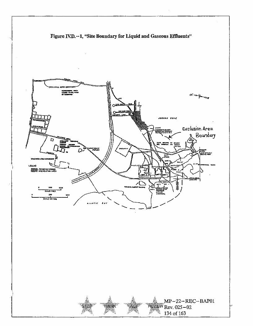
Figure IV.D.-1, "Site Boundary for Liquid and Gaseous Effluents"
STQJ~ T-. M
MP-22-REC-BAPO1,RE IjO Rev. 025 -02
134 of 163

IVE. Total Radiological Dose From Station Operation
CONTROLS
The annual dose or dose commitment to any REAL MEMBER OF THEPUBLIC, beyond the site boundary, from the Millstone Site is limited to less thanor equal to 25 mrem to the total body or any organ (except the thyroid, which islimited to less than or equal to 75 mrem).
APPLICABILITY: At all times.
ACTION:
With the calculated dose from the release of radioactive materials in liquid orgaseous effluents exceeding twice the limits of Controls IVD.2.a., IV.D.1.b., orIV.D.2.c. prepare and submit a Special Report to the Commission within 30 daysand limit the subsequent releases such that the dose commitment from the site toany REAL MEMBER OF THE PUBLIC from the Millstone Site is limited toless than or equal to 25 mrem to the total body or any organ (except thyroid,which is limited to less than or equal to 75 mrem) over 12 consecutive months.This Special Report shall include an analysis which demonstrates that radiationexposures from the site to any REAL MEMBER OF THE PUBLIC from theMillstone Site (including all effluent pathways and direct radiation) are less thanthe 40 CFR 190.
If the estimated doses exceed the above limits, the Special Report shall include arequest for a variance in accordance with the provisions of 40 CFR 190.Submittal of the report is considered a timely request, and a variance is granteduntil staff action on the request is complete.
SURVEILLANCE REGUIREMENTS
Cumulative dose contributions from liquid and gaseous effluents and directradiation from the Millstone Site shall be determined in accordance withSection II once per 31 days.
IVF. Bases
Section IVC.1. - Radioactive Liquid Effluent Monitoring Instrumentation
The radioactive liquid effluent instrumentation is provided to monitor andcontrol, as applicable, the releases of radioactive materials in liquid effluentsduring actual or potential releases of liquid effluents. The alarm/trip setpointsfor these instruments shall be calculated in accordance with the approvedmethods in the ODCM to ensure that the alarm/trip will occur prior to exceedingten times the limits of 10 CFR 20. The OPERABILITY and use of this
--• MP-22-REC-BAP01•-•-PTIK 'A •'-Rev. 025 - 02
'' 135 of 163

instrumentation is consistent with the requirements of General Design Criteria60, 63, and 64 of Appendix A to 10 CFR 50. Monitoring of the turbine buildingsumps and condensate polishing facility floor drains is not required due torelatively low concentrations of radioactivity possible.
Section IVC.2. - Radioactive Gaseous Effluent Monitoring Instrumentation
The radioactive gaseous effluent instrumentation is provided to monitor andcontrol, as applicable, the releases of radioactive materials in gaseous effluentsduring actual or potential releases. The alarm/trip setpoints for theseinstruments shall be calculated in accordance with the approved methods in theREMODCM to ensure that the alarm/trip will occur prior to exceeding the doserate limits, at any time, as specified in Section IVD.2.a. The OPERABILITYand use of this instrumentation is consistent with the requirements of GeneralDesign Criteria 60, 63, and 64 of Appendix A to 10 CFR 50.
Two types of radioactive gaseous effluent monitoring instrumentation, monitorsand samplers, are being used at MP2 vent and Millstone Stack. Monitors havealarm/trip setpoints and are demonstrated operable by performing one or moreof the following operations: CHANNEL CHECK, SOURCE CHECK,CHANNEL CALIBRATION, and CHANNEL FUNCTIONAL TEST Samplersare strictly collection devices made of canisters and filters. The CHANNELCHECK surveillance requirements are met through (1) documented observationof the in-service rad monitor sample flow prior to filter replacement; (2)documented replacement of in-line iodine and particulate filters; and (3)documented observation of sample flow following the sampler return to service.The flow indicator is the only indication available for comparison. Theseobservations adequately provide assurance that the sampler is operating and iscapable of performing its design function.
There are a number of gaseous release points which could exhibit very lowconcentrations of radioactivity. For all of these release paths, dose consequenceswould be insignificant due to the intermittent nature of the release and/or theextremely low concentrations of radioactivity. Since it is not cost-beneficial (norin many cases practical due to the nature of the release (steam) or theimpossibility of detecting such low levels), to monitor these pathways, it has beendetermined that these release paths require no monitoring or sampling.
Section IVD.L.a. - Radioactive Liquid Effluents Concentrations
This specification is provided to ensure that the concentration of radioactivematerials released in liquid waste effluents from the site will be less than tentimes the concentration levels specified in 10 CFR 20, Appendix B, Table 2. Thislimitation provides additional assurance that the levels of radioactive materials inbodies of water outside the site will result in exposures within: (1) the SectionII.A design objectives of Appendix I, 10 CFR 50, to an individual and (2) thelimits of 10 CFR 20 to the population. The concentration limit for noble gases is
M1 AT~k ~ MP-22-REC-BAP01."Rev 025-02
136 of 163
based upon the assumption that Xe-135 is the controlling radioisotope and itsconcentration in air (submersion) was converted to an equivalent concentrationin water using the methods described in International Commission onRadiological Protection (ICRP) Publication 2.
Section IV.D.1.b. - Radioactive Liquid Effluents Doses
This specification is provided to implement the requirements of Sections II.A,III.A, and IVA of Appendix I, 10 CFR 50. The specification implements theguides set forth in Section II.A of Appendix I. The Action statements provide therequired operating flexibility and at the same time implement the guides set forthin Section III.A of Appendix I to assure that the releases of radioactive materialin liquid effluents will be kept "as low as is reasonably achievable". The dosecalculations in the ODCM implement the requirements in Section III.A ofAppendix I that conformance with the guides of Appendix I is to be shown bycalculational procedures based on models and data such that the actual exposureof an individual through appropriate pathways is unlikely to be substantiallyunderestimated. The equations specified in the ODCM for calculating the dosesdue to the actual release rates of radioactive materials in liquid effluents areconsistent with the methodology provided in Regulatory Guide 1.109,"Calculation of Annual Doses to Man from Routine Releases of ReactorEffluents for the Purpose of Evaluating Compliance with 10 CFR 50, Appendix I,Revision 1, October 1977, and Regulatory Guide 1.113, "Estimating AquaticDispersion of Effluents from Accidental and Routine Reactor Releases for thePurpose of Implementing Appendix I," April 1977.
Section IV.D.2.a. - Radioactive Gaseous Effluents Dose Rate
This specification is provided to ensure that the dose rate at anytime fromgaseous effluents from all units on the site will be within the annual dose limits of10 CFR 20 for all areas offsite. The annual dose limits are the doses associatedwith the concentrations of 10 CFR 20, Appendix B, Table 2. These limits providereasonable assurance that radioactive material discharged in gaseous effluentswill not result in the exposure of an individual offsite to annual averageconcentrations exceeding the limits specified in Appendix B, Table 2 of 10 CFR20. For individuals who may, at times, be within the site boundary, the occupancyof that individual will be sufficiently low to compensate for any increase in theatmospheric diffusion factor above that for the site boundary. The specifiedrelease rate limits restrict, at all times, the corresponding gamma and beta doserates above background to an individual at or beyond the site boundary to lessthan or equal to 500 mrem/year to the total body or to less than or equal to 3000mrem/year to the skin. These release rate limits also restrict, at all times, thecorresponding thyroid or any other organ dose rate above background to a childvia the inhalation pathway to less than or equal to 1500 mrem/year.
-4- -MP-22-REC-BAP01STQ •1R.Aev. 025-02
-- 137 of 163

SECTION V
Millstone Unit 3
Radiological Effluent Controls
Docket Nos. 50-423
. MP -22-REC-BAPO1" ",, T IN.... .FM4EWRev. 025-02
138 of 163

SECTION V REMODCM UNIT THREE CONTROLS
VA. Introduction
The purpose of this section is to provide the following for Millstone Unit Three:
a. the effluent radiation monitor controls and surveillance requirements,
b. the effluent radioactivity concentration and dose controls andsurveillance requirements, and
c. the bases for the controls and surveillance requirements.
Definitions of certain terms are provided as an aid for implementation of thecontrols and requirements.
Some surveillance requirements refer to specific sub-sections in Sections I andII as part of their required actions.
VB. Definitions and Applicability and Surveillance Requirements
V.B.1 - Definitions
The defined terms of this sub-section appear in capitalized type and areapplicable throughout Section V.
1. ACTION - ACTION shall be that part of the control which prescribesremedial measures required under designated conditions.
2. CHANNEL OPERATIONAL TEST - A CHANNEL OPERATIONALTEST shall be the injection of a simulated signal into the channel as close tothe sensor as practicable to verify OPERABILITY of alarm, interlock and/ortrip functions. For digital instruments, the computer database may bemanipulated, in lieu of a signal injection, to verify operability of alarm and/ortrip functions.
The CHANNEL OPERATIONAL TEST shall include adjustments, asnecessary, of the alarm, interlock and/or trip setpoints such that the setpointsare within the required range and accuracy.
MPr-22-REC-BAPO1$0 -)A " W 025-02
139 of 163

3. CHANNEL CALIBRATION - A CHANNEL CALIBRATION shall be theadjustment, as necessary, of the channel such that it responds within therequired range and accuracy to known values of input. The CHANNELCALIBRATION shall encompass the entire channel including the sensorsand alarm, interlock and/or trip functions and may be performed by anyseries of sequential, overlapping, or total channel steps such that the entirechannel is calibrated.
4. CHANNEL CHECK - A CHANNEL CHECK shall be the qualitativeassessment of channel behavior during operation by observation. Thisdetermination shall include, where possible, comparison of the channelindication and/or status with other indications and/or status derived fromindependent instrument channels measuring the same parameter.
5. DOSE EQUIVALENT 1- 131 - DOSE EQUIVALENT 1- 131 shall be thatconcentration of 1- 131 (ltCigam) which alone would produce the sameCDE-thyroid dose as the quantity and isotopic mixture of 1-131, 1-132,1-133, 1-134, and 1-135 actually present. The thyroid dose conversionfactors used for this calculation shall be those listed under Inhalation inFederal Guidance Report No. 11 (FGR 11), "Limiting Values ofRadionuclide Intake and Air Concentration and Dose Conversion Factors forInhalation, Submersion and Ingestion."
6. MEMBER(S) OF THE PUBLIC - MEMBER(S) OF THE PUBLIC shallinclude all persons who are not occupationally associated with the plant.This category does not include employees of the licensee, its contractors orits vendors. Also excluded from this category are persons who enter the siteto service equipment or to make deliveries. This category does includepersons who use portions of the site for recreational, occupational, or otherpurposes not associated with the plant.
The term "REAL MEMBER OF THE PUBLIC" means an individual who isexposed to existing dose pathways at one particular location.
7. MODE - Refers to Mode of Operation as defined in Safety TechnicalSpecifications.
8. OPERABLE - OPERABILITY - An instrument shall be OPERABLE orhave OPERABILITY when it is capable of performing its specifiedfunctions(s) and when all necessary attendant instrumentation, controls,electrical power, or other auxiliary equipment that are required for theinstrument to perform its functions(s) are also capable of performing theirrelated support function(s).
9. SITE BOUNDARY - The SITE BOUNDARY shall be that line beyondwhich the land is not owned, leased, or otherwise controlled by the licensee.
... .. .. .. & MP-22-REC-BAP01
STA Rev. 025-02
140 of 163

10. SOURCE CHECK - A SOURCE CHECK shall be the qualitativeassessment of channel response when the channel sensor is exposed toradiation.
11. UNRESTRICTED AREA - Any area at or beyond the SITE BOUNDARYto which access is not controlled by the licensee for purposes of protection ofindividuals from exposure to radiation and radioactive materials or any areawithin the SITE BOUNDARY used for residential quarters or industrial,commercial, institutional and/or recreational purposes.
V.B.2 - Applicability
V.B.2.a - LIMITING CONDITIONS FOR OPERATION
1. Compliance with the Limiting Conditions for Operation contained in thesucceeding specifications is required during the OPERATIONAL MODESor other conditions specified therein; except that upon failure to meet theLimiting Conditions for Operation, the associated ACTION requirementsshall be met.
2. Noncompliance with a specification shall exist when the requirements of theLimiting Condition for Operation and associated ACTION requirements arenot met within the specified time intervals. If the Limiting Condition forOperation is restored prior to expiration of the specified time intervals,completion of the ACTION requirements is not required.
VB.2.b - SURVEILLANCE REQUIREMENTS
1. Surveillance Requirements shall be applicable during any condition specifiedfor individual Limiting Conditions for Operation unless otherwise stated inan individual Surveillance Requirement.
2. Each Surveillance Requirement shall be performed within the specified timeinterval with a maximum allowable extension not to exceed 25% of thesurveillance time interval.
3. Failure to perform a Surveillance Requirement within the allowedsurveillance interval, defined by Condition V.B.2.b(2), shall constitute afailure to meet the OPERABILITY requirements for a Limiting Conditionfor Operation. The time limits of the ACTION requirements are applicableat the time it is identified that a Surveillance Requirement has not beenperformed. The ACTION requirements may be delayed for up to 24 hours topermit the completion of the surveillance when the allowable outage timelimits of the ACTION requirements are less than 24 hours. SurveillanceRequirements do not have to be performed on inoperable equipment.
4 -4• MP -22--REC-BAP01'- ' ,..... Rev. 025-02
ý0:1--T ,141 of 163
4. Entry into any specified condition shall not be made unless the SurveillanceRequirement(s) associated with the Limiting Condition for Operation havebeen performed within the stated surveillance interval or as otherwisespecified.
VC. Radioactive Effluent Monitoring Instrumentation
1. Radioactive Liquid Effluent Monitoring Instrumentation
LIMITING CONDITIONS OF OPERATION
The radioactive liquid effluent monitoring instrumentation channels shownin Table VC.- 1 shall be OPERABLE with their Alarm/Trip setpoints set toensure that the limits of Specification VD.1.a are not exceeded. Thealarm/trip setpoints shall be determined in accordance with methodology andparameters as described in Section II.
APPLICABILITY: As shown in Table V.C. -1
ACTION:
a. With a radioactive liquid effluent monitoring instrumentation channelAlarm/Trip setpoint less conservative than required by the abovespecification, without delay suspend the release of radioactive liquideffluents monitored by the affected channel, or declare the channelinoperable, or change the setpoint so it is acceptably conservative.
b. With less than the minimum number of radioactive liquid effluentmonitoring instrumentation channels OPERABLE, take the actionshown in Thble V.C.- 1. Exert best efforts to restore the inoperableinstrumentation to OPERABLE status within 30 days and, ifunsuccessful, explain in the next Radioactive Effluent Release Reportwhy the inoperability was not corrected in a timely manner. Releasesneed not be terminated after 30 days provided the specified actions arecontinued.
SURVEILLANCE REQUIREMENTS
Each radioactive liquid effluent monitoring instrumentation channel shall bedemonstrated OPERABLE by performance of the CHANNEL CHECK,SOURCE CHECK, CHANNEL CALIBRATION, and CHANNELOPERATIONAL TEST at the frequencies shown in Table V.C.-2.
- ........ ....... MP-22-REC-BAP01S'•W Rev. 025 - 02
142 of 163

TABLE V.C.- 1Radioactive Liquid Effluent Monitoring Instrumentation
Instrument Minimum Applicability Action# Operable
1.Radioactivity Monitors Providing Alarm and Automatic Termination Of Releasea. Waste Neutralization Sump Monitor Condensate 1* ## DPolishing Facilityb. Turbine Building Floor Drains 1 # Bc. Liquid Waste Monitor 1 # Ad. RESERVEDe. Steam Generator Blowdown Monitor 1 ### B
2.Flow Rate Measurement Devices - No Alarm Setpoint Requirementsa. Waste Neutralization Sump Effluents 1" # Cb. RESERVEDc. Liquid Waste Effluent Line 1 # Cd. RESERVEDe. Steam Generator Blowdown Effluent Line 1 # C
* NA if tritium in the steam generators is less than detectable, or gamma radioactivity inthe steam generators is less than 5 x 10⁻⁷ OtCi/ml, or the sump is being directed toradwaste.
# At all times - which means that channels shall be OPERABLE and in service on acontinuous, uninterrupted basis, except that outages are permitted, for a maximum of12 hours, for the purpose of maintenance and performance of required test, checks,calibrations, or sampling associated with the instrument or any system or componentwhich affects functioning of the instrument.
## MODEs 1 -5, and MODE 6 when pathway is being used, except that outages arepermitted, for a maximum of hours, for the purpose of maintenance and performanceof required test, checks, calibrations, or sampling associated with the instrument orany system or component which affects functioning of the instrument. The monitormust be on-line with no unexpected alarms. When the affected discharge path isisolated in MODE 6, the applicable LCO and Surveillance Requirements are notapplicable.
### MODEs 1 -5, except that outages are permitted, for a maximum of 12 hours, for thepurpose of maintenance and performance of required test, checks, calibrations, orsampling associated with the instrument or any system or component which affectsfunctioning of the instrument. The monitor must be on-line with no unexpected alarms.
F STOP ~ACT.MP-22-REC-BAP01Rev. 025-02
143 of 163

SECTION VI. Summary of Changes
1.1 Revision 025-02
1.1.1 Created Summary of Changes Section.
1.1.2 Corrected Table I.D-3 Title to Unit 3 from Unit 2.
1.1.3 Re-numbered Table I.E-1 and changed number of locationsfrom 3 to 2 under Well Water.
1.1.4 Changed referenced document VB.1 definition 5. DOSEEQUIVALENT 1-131 to Federal Guidance Report No. 11 (FGR11), "Limiting Values of Radionuclide Intake and AirConcentration and Dose Conversion Factors for Inhalation,Submersion and Ingestion".
STýO THINK -~ACT~MP-22-REC-BAP01
R-WRev. 025-02144 of 163

TABLE V.C.-1ACTION STATEMENTS
Action A
With the number of channels OPERABLE less than required by the Minimum ChannelsOPERABLE requirements, effluent releases via this pathway may continue provided thatbest efforts are made to repair the instrument and that prior to initiating a release:
1. At least two independent samples are analyzed in accordance with the first SurveillanceRequirement of Specification V.D.1 .a. and;
2. The original release rate calculations and discharge line valving are independentlyverified by a second individual.
Action B
With the number of channels OPERABLE less than required by the Minimum ChannelsOPERABLE requirement, effluent releases via this pathway may continue provided bestefforts are made to repair the instrument and that grab samples are analyzed forgamma radioactivity at the lower limits of detection specified in Table I.C.-3:
1. At least once per 12 hours when the specific activity of the secondary coolant is greaterthan 0.01 RCi/gram DOSE EQUIVALENT 1-131, or
2. At least once per 24 hours when the specific activity of the secondary coolant is lessthan or equal to 0.01 RiCi/gram DOSE EQUIVALENT 1-131.
Action C
With the number of channels OPERABLE less than required by the Minimum ChannelsOPERABLE requirement, effluent releases via this pathway may continue provided thatbest efforts are made to repair the instrument and that the flow rate is estimated at leastonce per 4 hours during actual releases. Pump performance curves may be used toestimate flow.
Action D
With the number of channels OPERABLE less than required by the Minimum ChannelsOPERABLE requirements, effluent releases may continue provided that best efforts aremade to repair the instrument and that prior to initiating a release:
1. At least two independent samples are analyzed in accordance with the first SurveillanceRequirement of Specification V.D.I.a., and;
2. If one of the samples has gamma radioactivity greater than any of the lower limits ofdetection specified in Table I.C.-3, the original release rate calculations and dischargevalving are independently verified by a second individual.
- ... MP-22-REC-BAP01
ST, T--- •,Rev. 025-02
145 of 163

TABLE V.C.-2Radioactive Liquid Effluent Monitoring Instrumentation Surveillance Requirements I
Instrument
1.Radioactivity Monitors Providing Alarm and Automatic Termination Of Releasea. Waste Neutralization Sump Monitor D P R(2) QM)Condensate Polishing Facility
b. Turbine Building Floor Drains D M R(2) Q(M)
c. Liquid Waste Monitor D p R(2 ) Q(1)
d. Deleted
e. Steam Generator Blowdown Monitor D M R(2) QM)
2.Flow Rate Measurements
a. Waste Neutralization Sump Effluents D(3) NA R Qb. RESERVEDc. Liquid Waste Effluent Line D(3) N/A R Q
d. Deletede. Steam Generator Blowdown Effluent D(3) N/A R QLine
DMP
= Daily R == Monthly Q == Prior to each batch release N/A=
TABLE V.C. - 2TABLE NOTATION
Once every 18 monthsOnce every 3 monthsNot Applicable
(1) The CHANNEL OPERATIONAL TEST shall also demonstrate that automatic isolation of thispathway and control room alarm annunciation occur if any of the following conditionsexists:
a) Instrument indicates measured levels above the alarm/trip setpoint, or
b) Circuit failure (Alarm only), or Instrument indicates a downscale failure (Alarm only).
(2) The initial CHANNEL CALIBRATION shall be performed using one or more of the referencestandards certified by the National Institute of Standards and Technology (NIST) or usingstandards that have been obtained from suppliers that participate in measurementassurance activities of NIST. These standards shall permit calibrating the system over itsintended range of energy and measurement range. For subsequent CHANNELCALIBRATION, sources that have been related to the initial calibration shall be used.
(3) CHANNEL CHECK shall consist of verifying indication of flow during periods of release.CHANNEL CHECK shall be made at least once per 24 hours on days on which continuous,periodic, or batch releases are made.
STOP:,t HINK
ACThMP-22-REC-BAP01
Pit Rev. 025-02
146 of 163

2. Radioactive Gaseous Effluent Monitoring Instrumentation
LIMITING CONDITIONS OF OPERATION
The radioactive gaseous effluent monitoring instrumentation channels shownin Table VC. -3 shall be OPERABLE with their Alarm/Trip Setpoints set toensure that the limits of Specification V.D.2.a. are not exceeded. TheAlarm/Trip Setpoints of these channels shall be determined in accordancewith the methodology and parameters in Section II.
APPLICABILITY: As shown in Table VC.-3.
ACTION:
a. With a radioactive gaseous effluent monitoring instrumentation channelAlarm/Trip Setpoint less conservative than required by the abovespecification, without delay suspend the release of radioactive gaseouseffluents monitored by the affected channel, or declare the channelinoperable, or change the setpoint so it is acceptably conservative.
b. With the number of OPERABLE radioactive gaseous effluentmonitoring instrumentation channels less than the Minimum ChannelsOPERABLE, take the ACTION shown in Table VC.-3. Exert bestefforts to restore the inoperable instrumentation to OPERABLE statuswithin 30 days and, if unsuccessful, explain in the next RadioactiveEffluent Release Report why the inoperability was not corrected in atimely manner. Release need not be terminated after 30 days providedthe specified actions are continued.
SURVEILLANCE REQUIREMENT
Each radioactive gaseous effluent monitoring instrumentation channel shallbe demonstrated OPERABLE by performance of the CHANNEL CHECK,SOURCE CHECK, CHANNEL CALIBRATION, and CHANNELOPERATIONAL TEST at the frequencies shown in Table V.C.-4.
g•STQ .....N ,MP-22-REC-BAP01
Io 4 A. Rev. 025-02
147 of 163

TABLE V.C.-3Radioactive Gaseous Effluent Monitoring Instrumentation
Instrument Minimum Applicability ActionChannelsOperable
1.Millstone Unit 3 Ventilation Vent ('Turbine Building - HVR-RE10B, normal range only; high rangemonitor, HVR-RE10A, requirements are in the TRM)
a. Noble Gas Activity Monitor Providing Alarm 1 * Ab. Iodine Sampler 1 * B
c. Particulate Sampler 1 * Bd. Vent Flow Rate Monitor 1 * Ce. Sampler Flow Rate Monitor 1 * C
2.Millstone Stack - applicable to SLCRS (HVR-RE19B, normal range only; high range monitor,HVR-RE19A, requirements are in the TRM)
a. Noble Gas Activity Monitor Providing Alarm 1 * Ab. Iodine Sampler 1 * B
c. Particulate Sampler 1 * B
d. Process Flow Rate Monitor 1 * Ce. Sampler Flow Rate Monitor 1 * C
3.Engineered Safeguards Building Monitor (HVQ-RE49)a. Noble Gas Activity Monitor 1 * Db. Iodine Sampler 1 * Bc. Particulate Sampler 1 * Bd. Discharge Flow Rate Monitor 1 * Ee. Sampler Flow Rate Monitor 1 * C
TABLE V.C.-3Table Notations
Whenever the release path is in service. Outages are permitted for a maximum of 12hours for the purpose of maintenance and performance of required tests, checks,calibrations, or sampling associated with the instrument or any system or componentwhich affects functioning of the instrument.
MP-22-REC-BAPO1
TK Rev. 025-02
-. 148 of 163

TABLE V.C.-3ACTION STATEMENTS
Action A
With the number of channels OPERABLE less than required by the Minimum ChannelsOPERABLE requirement, effluent releases via this pathway may continue provided that
a) best efforts are made to repair the instrument and that grab samples are taken at leastonce per 12 hours and these samples are analyzed for radioactivity within 24 hours, OR
b) if the cause of the inoperability is solely due to a loss of annunciation in the controlroom and the Remote Indicating Controller (RIC) remains OPERABLE, perform achannel check at the RIC at least once per twelve hours and verify the indication hasnot alarmed.
Action B
With the number of samplers OPERABLE less than required by the Minimum ChannelsOPERABLE requirement, effluent releases via this pathway may continue provided thatthe best efforts are made to repair the instrument and that samples are continuouslycollected with auxiliary sampling equipment for periods of seven (7) days and analyzedfor principal gamma emitters with half lives greater than 8 days within 48 hours after theend of the sampling period. Auxiliary sampling must be initiatedwithin 12 hours afterinitiation of this ACTION statement. Auxiliary sampling outages are permitted for amaximum of 12 hours for the purpose of maintenance and performance of requiredtests, checks, calibrations, or sampling.
Action C
With the number of channels OPERABLE less than required by the Minimum ChannelsOPERABLE requirement, effluent releases via this pathway may continue provided thatbest efforts are made to repair the instrument and that the flow rate is estimated at leastonce per 5 hours.
Action D
With the number of channels OPERABLE less than required by the Minimum ChannelsOPERABLE requirement, effluent releases via this pathway may continue provided thatbest efforts are made to repair the instrument and that grab samples are taken at leastonce per 12 hours and these samples are analyzed for radioactivity within 24 hours.
Action E
With the number of channels OPERABLE less than required by the Minimum ChannelsOPERABLE requirement, effluent releases via this pathway may continue provided thatbest efforts are made to repair the instrument.
MP-22- REC-BAP01.: _,_:,.. ..-••-,- :-,•.•;•;, :.-4,• -÷,•.• .,:"". ..... ....M - E
STO, ,K .4•. R Rev. 025- 02
S149 of 163
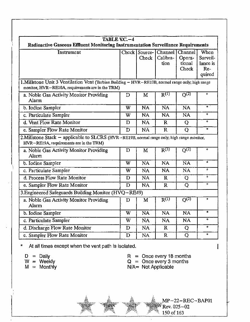
TABLE V.C.-4Radioactive Gaseous Effluent Monitoring Instrumentation Surveillance Requirements
Instrument Check Source- Channel Channel WhenCheck Calibra- Opera- Surveil-
tion tional lance isCheck Re-
I quired
1.Millstone Unit 3 Ventilation Vent (Turbine Building - HVR-RE10B, normal range only; high rangemonitor, HVR-RE10A, requirements are in the TRM)
a. Noble Gas Activity Monitor Providing D M R(1) Q(2 ) •Alarm
b. Iodine Sampler W NA NA NA
c. Particulate Sampler W NA NA NA *
d. vent Plow Rate Monitor D NA R Q *
e. Sampler Flow Rate Monitor D NA R Q *
2.Millstone Stack - applicable to SLCRS (HVR-RE19B, normal range only; high range monitor,HVR-RE19A, requirements are in the TRM)
a. Noble Gas Activity Monitor Providing D M R(3) Q(2 )
Alarm
b. Iodine Sampler W NA NA NA *
c. Particulate Sampler W NA NA NA *
d. Process Flow Rate Monitor D NA R Q *
e. Sampler Flow Rate Monitor D NA R Q *
3.Engineered Safeguards Building Monitor ({VQ-RE49)
a. Noble Gas Activity Monitor Providing D M R(1) Q( 2)
Alarm
b. Iodine Sampler W NA NA NA *
c. Particulate Sampler W NA NA NA *
d. Discharge Flow Rate Monitor D NA R Q *
e. Sampler Flow Rate Monitor D NA R Q *
* At all times except when the vent path is isolated. I
D = DailyW = WeeklyM = Monthly
R = Once every 18 monthsQ _=N/A =
Once every 3 monthsNot Applicable
AT-. •MP-22-REC-BAP01ST. P ... 1J' R••JV1Ew Rev. 025-02
150 of 163

TABLE V.C.-4Table Notations
(1) The initial CHANNEL CALIBRATION shall be performed using one or more of the referencestandards certified by the National Institute of Standards and Technology (NIST) or usingstandards that have been obtained from suppliers that participate in measurementassurance activities of NIST These standards shall permit calibrating the system over itsintended range of energy and measurement range. For subsequent CHANNELCALIBRATION, sources that have been related to the initial calibration shall be used.
(2) The CHANNEL OPERATIONAL TEST shall also demonstrate that control room alarm
annunciation occurs if any of the following conditions exist:
a) Instrument indicates measured levels above the Alarm Setpoint, or
b) Circuit failure, or
c) Instrument indicates a downscale failure.
(3) The CHANNEL CALIBRATION shall include the use of a known source whose strength isdetermined by a detector which has been calibrated to an NIST source. These sourcesshall be in know, reproducible geometry.
STOPkk
T."4-
P
..... MP-22-REC-BAP01
W 025-02
151 of 163

VD. Radioactive Effluents Concentrations And Dose Limitations
1. Radioactive Liquid Effluents
a. Radioactive Liquid Effluents Concentrations
LIMITING CONDITIONS OF OPERATION
The concentration of radioactive material released from the site (seeFigure VD.-1) shall be limited to ten times the concentrations specifiedin 10 CFR 20, Appendix B, Table 2, Column 2 for radionuclides otherthan dissolved or entrained noble gases. For dissolved or entrainednoble gases, the concentration shall not exceed 2 x 10⁻⁴ [Ci/ml totalactivity.
APPLICABILITY: At all times.
ACTION:
With the concentration of radioactive material released from the siteexceeding the above limits, restore the concentration to within the abovelimits within 15 minutes.
SURVEILLANCE REOUIREMENTS
1) Radioactive liquid wastes shall be sampled and analyzed accordingto the sampling and analysis program specified in Section I.
2) The results of the radioactive analysis shall be used in accordancewith the methods of Section II to assure that the concentrations atthe point of release are maintained within the limits of SpecificationVD.1.a.
NkL •MP-22-REC-BAP01TOP THN : Rev. 025-02
152 of 163

b. Radioactive Liquid Effluents Doses
LIMITING CONDITIONS OF OPERATION
The dose or dose commitment to any REAL MEMBER OF THEPUBLIC from radioactive materials in liquid effluents from Unit 3released from the site (see Figure VD.-1) shall be limited:
a. During any calendar quarter to less than or equal to 1.5 mrem to thetotal body and to less than or equal to 5 mrem to any organ; and,
b. During any calendar year to less than or equal to 3 mrem to the totalbody and to less than or equal to 10 mrem to any organ.
APPLICABILITY: At all times.
A-CTION:
a. With the calculated dose from the release of radioactive materials inliquid effluents exceeding any of the above limits prepare and submitto the Commission within 30 days a Special Report which identifiesthe cause(s) for exceeding the limit(s) and defines the correctiveactions to be taken to reduce the releases of radioactive materials inliquid effluents during the remainder of the current calendar quarterand the remainder of the calendar year so that the cumulative doseor dose commitment to any REAL MEMBER OF THE PUBLICfrom such releases during the calendar year is within 3 mrem to thewhole body and 10 mrem to any organ.
SURVEILLANCE REOUIREMENTS
1) Dose Calculations. Cumulative dose contributions from liquideffluents for the current calendar quarter and the current calendaryear shall be determined in accordance with the methodology andparameters in Section II at least once per 31 days.
2) Relative accuracy or conservatism of the calculations shall beconfirmed by performance of the Radiological EnvironmentalMonitoring Program as detailed in Section I.
...... MP-22-REC-BAP01%OTN -A R VOW Rev. 025-02
153 of 163

2. Radioactive Gaseous Effluents
a. Radioactive Gaseous Effluents Dose Rate
LIMITING CONDITIONS OF OPERATION
The dose rate, at any time, offsite (see Figure V.D.- 1) due toradioactive materials released in gaseous effluents from the site shall belimited to the following values:
a. The dose rate limit for noble gases shall be less than or equal to 500mrem/yr to the total body and less than or equal to 3000 mrem/yr tothe skin; and,
b. The dose rate limit due to inhalation for Iodine-131, Iodine-133,'Tritium, and for all radioactive materials in particulate form withhalf lives greater than 8 days shall be less than or equal to 1500mrem/yr to any organ.
APPLICABILITY: At all times.
ACTION:
With the dose rate(s) exceeding the above limits, decrease the releaserate to comply with the limit(s) given in Specification VD.2.a. within 15minutes.
SURVEILLANCE REOUIREMENTS
1) The release rate, at any time, of noble gases in gaseous effluentsshall be controlled by the offsite dose rate as established inSpecification VD.2.a. The corresponding release rate shall bedetermined in accordance with the methodology of Section II.
2) The noble gas effluent monitors of ThbleVC.-3 shall be used tocontrol release rates to limit offsite doses within the valuesestablished in Specification V.D.2.a.
3) The release rate of radioactive materials in gaseous effluents shallbe determined by obtaining representative samples and performinganalyses in accordance with the sampling and analysis program,specified in Section I. The corresponding dose rate shall bedetermined using the methodology given in Section II.
-... .. MP-22-REC-BAP01TI• 'fIN-K 2'T" R•_WW Rev. 025-02
- . 154 of 163

b. Radioactive Gaseous Effluents Noble Gas Dose
LIMITING CONDITIONS OF OPERATION
The air dose offsite (see Figure VD.-1) due to noble gases releasedfrom Unit 3 in gaseous effluents shall be limited to the following:
a. During any calendar quarter: Less than or equal to 5 mrad forgamma radiation and less than or equal to 10 mrad for betaradiation, and
b. During any calendar year: Less than or equal to 10 mrad for gammaradiation and less than or equal to 20 mrad for beta radiation.
APPLICABILITY: At all times.
ACTION:
a. With the calculated air dose from radioactive noble gases in gaseouseffluents exceeding any of the above limits prepare and submit to theCommission within 30 days a Special Report which identifies thecause(s) for exceeding the limit(s) and defines the corrective actionsto be taken to reduce the releases of radioactive noble gases ingaseous effluents during the remainder of the current calendarquarter and during the remainder of the calendar year so that thecumulative dose during the calendar year is within 10 mrad forgamma radiation and 20 mrad for beta radiation.
SURVEILLANCE REOUIREMENTS
1) Dose Calculations - Cumulative dose contributions for the currentcalendar quarter and current calendar year shall be determined inaccordance with Section II once every 31 days.
2) Relative accuracy or conservatism of the calculations shall beconfirmed by performance of the Radiological EnvironmentalMonitoring Program as detailed in Section I.
S &..MP-22-REC-BAP01
TP -THNK AN Q . VW: Rev. 025-02155 of 163

c. Gaseous Effluents - Doses from Radionuclides Other than Noble Gas
LIMITING CONDITIONS OF OPERATION
The dose to any REAL MEMBER OF THE PUBLIC from Iodine-131,Iodine-133, Tritium, and radioactive materials in particulate form withhalf lives greater than 8 days in gaseous effluents released offsite fromUnit 3 released offsite (see Figure VD. -1) shall be limited to thefollowing:
a. During any calendar quarter: Less than or equal to 7.5 mrem to anyorgan and,
b. During any calendar year: Less than or equal to 15 mrem to any
organ.
APPLICABILITY: At all times.
ACTION:
c. With the calculated dose from the release of radioiodines,radioactive materials in particulate form, or radionuclides other thannoble gases in gaseous effluents exceeding any of the above limitsprepare and submit to the Commission within 30 days a SpecialReport which identifies the cause(s) for exceeding the limit anddefines the corrective actions to be taken to reduce the releasesduring the remainder of the current calendar quarter and during theremainder of the calendar year so that the cumulative dose or dosecommitment to any REAL MEMBER OF THE PUBLIC from suchreleases during the calendar year is within 15 mrem to any organ.
SURVEILLANCE REOUIREMENTS
1) Dose Calculations - Cumulative dose contributions for the currentcalendar quarter and current calendar year shall be determined inaccordance with Section II once every 31 days.
2) Relative accuracy or conservatism of the calculations shall beconfirmed by performance of the Radiological EnvironmentalMonitoring Program as detailed in Section I.
MP-22-REC-BAP01
STOP .... ACT REVI.W Rev. 025-02
156 of 163

Figure V.D.- 1, "Site Boundary for Liquid and Gaseous Effluents"
ISTMOV-7 T RM WK- ACTVMP-22-REC-BAP01Rev. 025-02
- 157 of 163

V.E. Total Radiological Dose From Station Operations
CONTROLS
The annual dose or dose commitment to any REAL MEMBER OF THEPUBLIC, beyond the site boundary, from the Millstone Site is limited to less thanor equal to 25 mrem to the total body or any organ (except the thyroid, which islimited to less than or equal to 75 mrem).
APPLICABILITY: At all times.
ACTION:
With the calculated dose from the release of radioactive materials in liquid orgaseous effluents exceeding twice the limits of Controls V.D.1.b., VD.2.b., orV.D.2.c. prepare and submit a Special Report to the Commission within 30 daysand limit the subsequent releases such that the dose commitment from the site toany REAL MEMBER OF THE PUBLIC from the Millstone Site is limited toless than or equal to 25 mrem to the total body or any organ (except thyroid,which is limited to less than or equal to 75 mrem) over consecutive months.This Special Report shall include an analysis which demonstrates that radiationexposures from the site to any REAL MEMBER OF THE PUBLIC from theMillstone Site (including all effluent pathways and direct radiation) are less thanthe 40 CFR 190 Standard.
If the estimated doses exceed the above limits, the Special Report shall include arequest for a variance in accordance with the provisions of 40 CFR 190.Submittal of the report is considered a timely request, and a variance is granteduntil staff action on the request is complete.
SURVEILLANCE REOUIREMENTS
Cumulative dose contributions from liquid and gaseous effluents and directradiation from the Millstone Site shall be determined in accordance with SectionII once per 31 days.
VE Bases
Section VC.1. - Radioactive Liquid Effluent Monitoring Instrumentation
The radioactive liquid effluent instrumentation is provided to monitor andcontrol, as applicable, the releases of radioactive materials in liquid effluentsduring actual or potential releases of liquid effluents. The Alarm/Trip Setpointsfor these instruments shall be calculated and adjusted in accordance with themethodology and parameters in Section II to ensure that the alarm/trip will occurprior to exceeding ten times the limits of 10 CFR 20. The OPERABILITY and
MP-22-REC-BAP01
S Rev 025-02
158 of 163

use of this instrumentation is consistent with the requirements of General DesignCriteria 60, 63, and 64 of Appendix A to 10 CFR 20 Part 50.
OPERABILITY of a radiation monitor is determined by its ability to perform itsspecified function. The specified function of the radioactivity monitors listed inTable VC.-1 is to provide Control Room alarm annunciation and automatictermination of release. The monitor must be on-line with no unexpected alarmsin order to perform its specified function.
Definition B.7 states a component is OPERABLE when it is capable ofperforming its specified function. The monitors are described in Tables VC.-1and VC.-2 as "Radioactivity Monitors Providing Alarm and AutomaticTermination of Releases." Table VC.-2 Note 1 requires that the AnalogChannel Operational Test (ACOT) demonstrate that automatic isolation and"control room annunciation" occur. Control room annunciation cannot occurunless the monitor is on line (i.e. in communication with the RMS computer.).Section VC.1. Surveillance Requirement requires that the ACOT be performedto demonstrate OPERABILITY. General Design Criteria 64 states in part:"Means shall be provided for monitoring effluent discharge paths forradioactivity." Regulatory Guide 1.21 Appendix A describes a monitor programthat is acceptable to the Regulatory staff. Under Section B of Appendix A,"LIQUID EFFLUENTS," the first paragraph states in part: "During the releaseof radioactive wastes, the effluent control monitor should be set to alarm and toinitiate automatic closure..."
Certain of the monitors listed in Table VC.- 1 are designed to operate withoutsample pumps. These monitors utilize pressure in the effluent line duringdischarge to providesample flow and sample pressure. Low sample flow and/orlow sample pressure alarms may be received when no discharge is in progress.These are expected alarms. Sample flow and/or sample pressure will return tonormal when the discharge is initiated. These alarms will clear when dischargebegins. The monitors are OPERABLE since they are able to perform theirspecified function with the expected alarms in.
Table V.C.-1 note ## requires entry into the radioactive liquid effluentmonitoring action statements whenever the radiation monitors are not availablein the required MODE. This note applies to items L.a (3CND-RE07, WasteNeutralization Sump), 1.d (3LWC-RE65, Regenerate Evaporator Monitor), andi.e (3SSR-RE08, Steam Generator Blowdown Monitor) in Table VC.- 1. Theoriginal issue of this requirement (as a Technical Specification) in January 1986stated the applicability was "At all times." Technical Specification Amendment 22added "APPLICABILITY" to Table VC.- 1 (then Tech Spec Table 3.3- ). Theapplicability added in Amendment 22 is the present wording. The letter 1312821,
STO~P TO MP-22-REC-BAP01-,•-•:,- RE•I W Rev. 025-02
159 of 163

dated February 24, 1988, in the following sections discusses the change requestand are quoted below:
• In "Discussion": "The proposed changes will now explicitly allow a monitorto be taken out of service for up to hours for maintenance/testing withoutentering the ACTION statement."
In "Significant Hazards Consideration" item 1: "the proposed changes wouldonly allow these radiation monitors to be out of service for a short period oftime (12 hours)."
In "Significant Hazards Consideration" item 2: "The proposed changes alsohave no effect on alarm setpoints or control functions. Further, no operatoractions that are required to mitigate any accident rely solely on thesemonitors, and these monitors provide no protective functions."
Technical Specification Amendment 22 provided for the following:
a allowance for planned inoperability of monitoring instrumentation for up tohours for the purpose of maintenance and performance of required test,check, calibration or sampling
0 a requirement to initiate auxiliary sampling within hours after inoperabilityof certain gaseous effluent monitors
* allowance for inoperability of certain effluent monitoring instrumentation,during MODE 6 (refueling) when the effluent pathway is not being used.
Section VC.2. - Radioactive Gaseous Effluent Monitoring Instrumentation
The radioactive gaseous effluent instrumentation is provided to monitor andcontrol, as applicable, the releases of radioactive materials in gaseous effluentsduring actual or potential releases of gaseous effluents. The Alarm/TripSetpoints for these instruments shall be calculated and adjusted in accordancewith the methodology and parameters in Section II to ensure that the alarm/tripwill occur prior to exceeding the limits of SectionV.D.2.a. The OPERABILITYand use of this instrumentation is consistent with the requirements of GeneralDesign Criteria 60, 63, and 64 of Appendix A to 10 CFR 20 Part 50.
The sensitivity of any noble gas activity monitors used to show compliance withthe gaseous effluent release requirements of Specification VC.2.a shall be suchthat concentrations as low as 1 x 10⁻⁶ [tCi/cc are measurable.
The vent normal range radiation monitor, HVR*10B, satisfies the requirementsof SectionV.C.2. for Unit 3 releases to the vent which is located on the turbine
MP-22-REC-BAP01STOP• •T1II ,ACT ..... Q • Rev. 025-02
160 of 163

building. There are no requirements in the REMODCM associated with the venthigh range radiation monitor, HVR*10A.
The. SLCRS normal range radiation monitor, HVR*19B, satisfies therequirements of SectionV.C.2. for Unit 3 releases to the Millstone Stack. Thereare no requirements in the REMODCM associated with the SLCRS high rangeradiation monitor, HVR*19A.
Section VD.1.a. - Radioactive Liquid Effluents Concentrations
This specification is provided to ensure that the concentration of radioactivematerials released in liquid waste effluents from the site will be less than tentimes the concentration levels specified in 10 CFR Part 20, Appendix B, Thble 2.This limitation provides additional assurance that the levels of radioactivematerials in bodies of water outside the site will result in exposures within: (1)the Section II.A design objectives of Appendix I, 10 CFR Part 50, to an individualand (2) the limits of 10 CFR 20.1301 to the population. The concentration limitfor noble gases is based upon the assumption that Xe- 135 is the controllingradioisotope and its concentrations in air (submersion) was converted to anequivalent concentration in water using the methods described in InternationalCommission on Radiological Protection (ICRP) Publication 2.
Section VD.1.b. - Radioactive Liquid Effluents Doses
This specification is provided to implement the requirements of Sections II.A.,III.A., and IVA. of Appendix I, 10 CFR Part 50. The specification implementsthe guides set forth in Section II.A of Appendix I. The ACTION statementsprovide the required operating flexibility and at the same time implement theguides set forth in Section III.A of Appendix I to assure that the releases ofradioactive material in liquid effluents will be kept "as low as is reasonablyachievable." The dose calculation methodology and parameters in Section IIimplement the requirements in Section III.A of Appendix I that conformancewith the guides of Appendix I is to be shown by calculational procedures basedon models and data such that the actual exposure of an individual throughappropriate pathways is unlikely to be substantially underestimated. Theequations specified in Section II for calculating the doses due to the actualrelease rates of radioactive materials in liquid effluents will be consistent with themethodology provided in Regulatory Guide 1.109, "Calculation of Annual Dosesto Man from Routine Releases of Reactor Effluents for the Purpose ofEvaluating Compliance with 10 CFR Part 50, Appendix I, Revision 1, October1977, and Regulatory Guide 1.113, "Estimating Aquatic Dispersion of Effluentsfrom Accidental and Routine Reactor Releases for the Purpose of ImplementingAppendix I," April 1977.
...........MP-22-REC-BAP01ST4JP •Y.. .K ACT REV•X\Rev. 025-02
161 of 163

Section VD.2.a.- Radioactive Gaseous Effluents Dose Rate
This specification will ensure that the dose from gaseous effluents from all unitson the site will be within the annual dose limits of 10 CFR Part 20 for all areasoffsite. The annual dose limits specified in this section are the dose limits fromthe version of 10 CFR Part 20 prior to 1994. Annual dose limit in the currentversion of 1OCFR20 were reduced from 500 to 100 mrem. But REMODCMrestrictions will not allow the current annual dose limit to be exceeded becausethe REMODCM requires termination, within fifteen minutes, of any releasewhich exceed the setpoint and much lower annual dose limits from 10CFR50,Appendix I are implemented. For individuals who may, at times, be within theSITE BOUNDARY, the occupancy of that individual will be usually besufficiently low to compensate for any increase in the atmospheric diffusionfactor above that for the SITE BOUNDARY. The specified release rate limitsrestrict, at all times, the corresponding gamma and beta dose rates abovebackground to an individual at or beyond the SITE BOUNDARY to less than orequal to 500 mrem/year to the whole body or to less than or equal to 3000mrem/year to the skin. These release rate limits also restrict, at all times, thecorresponding thyroid or any other organ dose rate above background to a childvia the inhalation pathway to less than or equal to 1500 mrem/year.
Section VD.2.b. - Radioactive Gaseous Effluents Noble Gas Dose
This specification is provided to implement the requirements of Sections II.B.,III.A., and IV.A. of Appendix I, 10 CFR Part 50. The specification implementsthe guides set forth in Section II.B of Appendix I. The ACTION statementsprovide the required operating flexibility and at the same time implement theguides set forth in Section VA. of Appendix I to assure that the releases ofradioactive material in gaseous effluents will be kept "as low as is reasonablyachievable." The Surveillance Requirements implement the requirements inSection III.A. of Appendix I that conformance with the guides of Appendix I beshown by calculational procedures based on models and data such that the actualexposure of an individual through the appropriate pathways is unlikely to besubstantially underestimated. The dose calculations established in Section II forcalculating the doses due to the actual release rates of radioactive noble gases ingaseous effluents will be consistent with the methodology provided in RegulatoryGuide 1.109, "Calculational of Annual Doses to Man from Routine Releases ofReactor Effluents for the Purpose of Evaluating Compliance with 10 CFR Part50, Appendix I," Revision 1, October 1977 and Regulatory Guide 1.111,"Methods for Estimating Atmospheric Transport and Dispersion of GaseousEffluents in Routine Releases from Light-Water-Cooled Reactors," Revision 1,July 1977.
The Section II equations provided for determining the air doses at the siteboundary are based upon utilizing successively more realistic dose calculationalmethodologies. More realistic dose calculational methods are used wheneversimplified calculations indicate a dose approaching a substantial portion of the
... •4 MP-22-REC-BAP01
.T.P......M "AT .W--1EW Rev 025-02
162 of 163

regulatory limits. The methods used are, in order, previously determined airdose per released activity ratio, historical meteorological data and actualradionuclide mix released, or real time meteorology and actual radionuclidesreleased.
Section VD.2.c. - Radioactive Gaseous Effluents for Radionuclides Other ThanNoble Gas
These specifications are provided to implement the requirements of SectionsII.C., III.A., and IVA. of Appendix I, 10 CFR Part 50. The specifications are theguides set forth in Section II.C. of Appendix I. The ACTION statements providethe required operating flexibility and at the same time implement the guides setforth in Section IVA. of Appendix I to assure that the releases of radioactivematerials in gaseous effluents will be kept "as low as is reasonably achievable."The Section II calculational methods specified in the surveillance requirementsimplement the requirements in Section III.A. of Appendix I that conformancewith the guides for Appendix I be shown by calculational procedures based onmodels and data such that the actual exposure of an individual throughappropriate pathways is unlikely to be substantially underestimated. The SectionII calculational methodology and parameters for calculating the doses due to theactual release rates of the subject materials are consistent with the methodologyprovided in Regulatory Guide 1.109, "Calculating of Annual Dose to Man fromRoutine Releases of Reactor Effluents for the Purpose of Evaluating Compliancewith 10 CFR Part 50, Appendix I," Revision I, October 1977 and RegulatoryGuide 1.111, "Methods for Estimating Atmospheric Transport and Dispersion ofGaseous Effluents in Routine Releases from Light-Water-Cooled Reactors,"Revision I, July 1977. The release rate specifications for radioiodines,radioactive material in particulate form and radionuclides other than noble gasesare dependent on the existing radionuclide pathways to man. The pathways thatare examined in the development of these calculations are: 1) individualinhalation of airborne radionuclides, 2) deposition of radionuclides onto greenleafy vegetation with subsequent consumption by man, (3) deposition onto grassyareas where milk animals and meat producing animals graze with consumption ofthe milk and meat by man, and 4) deposition on the ground with subsequentexposure of man.
Section VE. - Total Radiological Dose from Station Operations
This specification is provided to meet the dose limitations of 40 CFR 190. For thepurpose of the Special Report, it may be assumed that the dose commitment toany REAL MEMBER OF THE PUBLIC from other fuel cycle sources isnegligible, with the exception that dose contributions from other nuclear fuelcycle facilities at the same site or within a radius of 5 miles must be considered.
-J .. . MP-22-REC-BAP01S"P T., ,, •. .•N W Rev. 025 -02
163 of 163