Attached is the submittal for the Switchboards and ... IN...Waynetown Water System Improvements...
39
Waynetown Water System Improvements Division “A”-New Water Treatment Plant Town of Waynetown, IN Submittal Review Sheet Attached is the submittal for the Switchboards and Panelboards for the Waynetown Water Systems Improvements Project for your review and approval. Thieneman Construction has reviewed the submittal information and added the following notes for your review, approval, and consideration: Items for Commonwealth Engineers: Items for Supplier: 1. Supply materials as requested by TCI in conformance with the project schedule. If you have any questions on this submittal information, please contact Travis Smith at (317) 750-9622. Thieneman Construction requests your review, approval, and return of one (1) copy of the approved submittals. Project Name: Waynetown Water Systems Improvements Contractor: Thieneman Construction, Inc. Subcontractor / Supplier: Sun Electric Submittal Number: DS-23-04 Submittal Specification Section: DS-23 Item Description: 262413 – Switchboards / 262416 - Panelboards Quantity of Submittals: 1 – Electronic Comments: See Above Quantity of Approved Submittals to be Returned: 1 – Electronic Signature: Travis Smith CONTRACTOR’S CERTIFICATION Submittal material has been reviewed for compliance with specifications and drawings. Required field measurements have been verified. The work shown on this submittal has been coordinated with other submittals affected by this work. All data has been checked by the Contractor and any variations from the specifications or drawings have been noted. The work described on the submittal material is recommended by the Contractor, and the guarantee in the specifications will apply: Contractor: Thieneman Construction Approved: Travis Smith Date: 10/13/16 Electrical Notes: For PDC-1 provide a minimum of 6 spare circuits.
Transcript of Attached is the submittal for the Switchboards and ... IN...Waynetown Water System Improvements...

Waynetown Water System Improvements
Division “A”-New Water Treatment Plant
Town of Waynetown, IN
Submittal Review Sheet
Attached is the submittal for the Switchboards and Panelboards for the Waynetown Water Systems
Improvements Project for your review and approval. Thieneman Construction has reviewed the
submittal information and added the following notes for your review, approval, and consideration:
Items for Commonwealth Engineers:
Items for Supplier:
1. Supply materials as requested by TCI in conformance with the project schedule.
If you have any questions on this submittal information, please contact Travis Smith at (317) 750-9622. Thieneman
Construction requests your review, approval, and return of one (1) copy of the approved submittals.
Project Name: Waynetown Water Systems Improvements
Contractor: Thieneman Construction, Inc.
Subcontractor / Supplier: Sun Electric
Submittal Number: DS-23-04
Submittal Specification Section: DS-23
Item Description: 262413 – Switchboards / 262416 - Panelboards
Quantity of Submittals: 1 – Electronic
Comments: See Above
Quantity of Approved Submittals to be Returned: 1 – Electronic
Signature: Travis Smith
CONTRACTOR’S CERTIFICATION Submittal material has been reviewed for compliance with specifications and drawings. Required field measurements have been verified. The work shown on this submittal has been coordinated with other submittals affected by this work. All data has been checked by the Contractor and any variations from the specifications or drawings have been noted. The work described on the submittal material is recommended by the Contractor, and the guarantee in the specifications will apply:
Contractor: Thieneman Construction
Approved: Travis Smith
Date: 10/13/16
Electrical Notes: For PDC-1 provide a minimum of 6 spare circuits.

Detail Bill of Material Page 1 of 1
Project Name: Waynetown WTP Improvments Negotiation No: IN870419X6K1 General Order No:
Alternate No: 0001
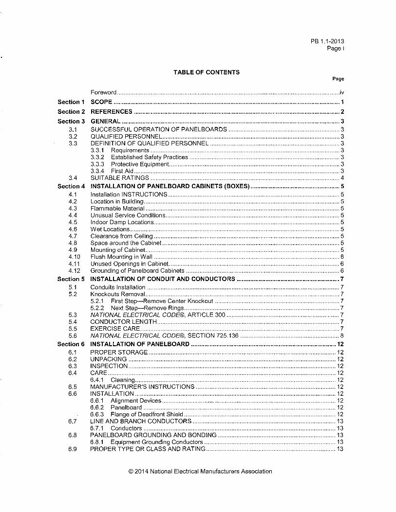
Item No. Qty Product Description 1 Panelboards 36 Circuits, 400A, Fully Rated, 480Y/277V 3Ph 4W, Copper Bus,
50k AIC, 250A, HJD 3P Main Breaker[Top Fed], Surface Mounted
Catalog No P3D400BT36CD01 Designation PDC-1
Qty List of Materials 1 250A, HJD 3P Main Breaker 2 50A, 3P HFD Branch Breaker 3 80A, 3P HFD Branch Breaker 2 30A, 3P HFD Branch Breaker 5 20A, 3P HFD Branch Breaker 1 Copper Main Bus, 400 Amps 1 Density Rated Cu Main Bus (1000A per sq. inch) 1 Std. Bolted Cu Ground Bar (Cu Cable Only) 1 Panel Nameplate - White with Black Letters 1 Type 1 Enclosure: EZB2072R 1 EZ Trim, Door in Door, Concealed Hardware: EZT2072S
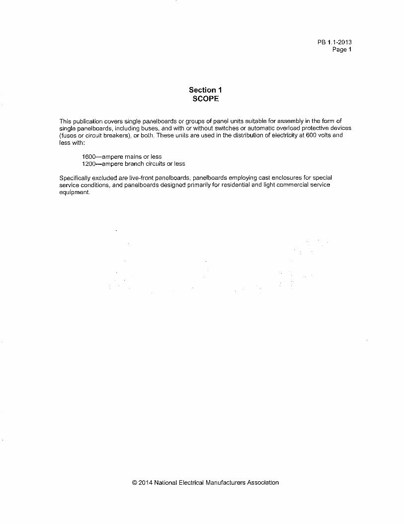
Item No. Qty Product Description 1 Panelboards 54 Circuits, 225A, Fully Rated, 208Y/120V 3Ph 4W, Copper Bus,
10k AIC, 150A, 3P EDB Main Breaker[Top Fed], Surface Mounted
Catalog No P1A225BT54CD01 Designation LP-1
Qty List of Materials 1 150A, 3P EDB Main Breaker 1 30A, 1P QBGFT Branch Breaker, GFCI - 5mA 10 20A, 1P QBGFT Branch Breaker, GFCI - 5mA 35 20A, 1P BAB Branch Breaker 1 1P BAB Branch Provision Only 1 30A, 2P BAB Branch Breaker 2 20A, 2P BAB Branch Breaker 1 40A, 1P QBGFT Branch Breaker, GFCI - 5mA 1 Copper Main Bus, 225 Amps 1 Density Rated Cu Main Bus (1000A per sq. inch) 1 Std. Bolted Cu Ground Bar (Cu Cable Only) 1 Panel Nameplate - White with Black Letters 1 Type 1 Enclosure: EZB2060R 1 EZ Trim, Door in Door, Concealed Hardware: EZT2060S
Eaton Selling Policy 25-000 applies.
All orders must be released for manufacture within 90 days of date of order entry. If approval drawings are required, drawings must be returned
approved for release within 60 days of mailing. If drawings are not returned accordingly, and/or if shipment is delayed for any reason, the price of the
order will increase by 1.0% per month or fraction there of for the time the shipment is delayed.

1 2
3 4
5 6
7 8
9 10
11 12
13 14
15 16
17 18
19 20
21 22
23 24
25 26
27 28
29 30
31 32
33 34
35 36
Main Breaker 250AHJD3250, Vert Mtd.
Neutral
HFD308080A
HFD308080A
HFD308080A
HFD305050A
HFD305050A
HFD303030A
HFD303030A
HFD302020A
HFD302020A
HFD302020A
HFD302020A
HFD302020A
General Information (Section 1 of 1)
Service Voltage: 480Y/277V 3Ph 4W Enclosure: Type 1Bus Rating & Type: 400A Copper Neutral Rating: 400AGround Bar: Std. Bolted Copper, Cu cable onlyS.C. Rating: 50k A.I.C. Fully Rated
Main Device Type: Main Breaker - Top Cable EntryMain Terminals: Mechanical - (1) #4-350 kcmil (Cu/Al)Neutral Terminals: Mechanical - (2) #4-500 kcmil (Cu/Al)Box Catalog No.: EZB2072RTrim: EZ Trim, Door in Door, Concealed Hardware (EZT2072S)
Surface Mounted
Box Dimensions: 72.00" [1828.8mm]H x 20.00" [508.0mm]W x 5.75" [146.1mm]DMin. Gutter Size: Top = 5.5" [139.7mm] Bottom = 5.5" [139.7mm]
Left = 4" [101.6mm] Right = 4" [101.6mm]
Panel ID Nameplate: (1) PDC-1Type: Plastic, adhesive-backed (2) 480Y/277V 3Ph 4WColor: White with Black Letters (3)
UL
Trim Lock: Standard Lock & Key (Keyed WEM2)Circuit Directory: Plastic Sleeve with CardDensity Rated BusMain Circuit Breaker Trip Type: Thermal-Magnetic.
Branch DevicesQty Poles Trip Frame Amps kAIC3 3 80 HFD 100 502 3 50 HFD 100 502 3 30 HFD 100 505 3 20 HFD 100 50Main DevicesQty Poles Trip Frame Amps kAIC1 3 250 HJD 250 50
Device Modifications:Ref # Description
Notes:
NEG-ALT Number
PREPARED BY DATE
APPROVED BY DATE
VERSION
REVISION DWG SIZE
JOB NAME
DESIGNATION
TYPE
G.O.
DRAWING TYPE
ITEM SHEET
The information on this document is created by Eaton Corporation. It is disclosed in confidence and it is only to be used for the purpose in which it is supplied.
IN870419X6K1-0001
MICHAEL MAHER 9/28/2016
1.0.0.6
0 A
EatonWaynetown WTP ImprovmentsPDC-1
PRL3a Customer Approval
1 of 1
PROV
1 2
3 4
5 6
7 8
9 10
11 12
13 14
15 16
17 18
19 20
21 22
23 24
25 26
27 28
29 30
31 32
33 34
35 36
37 38
39 40
41 42
43 44
45 46
47 48
49 50
51 52
53 54
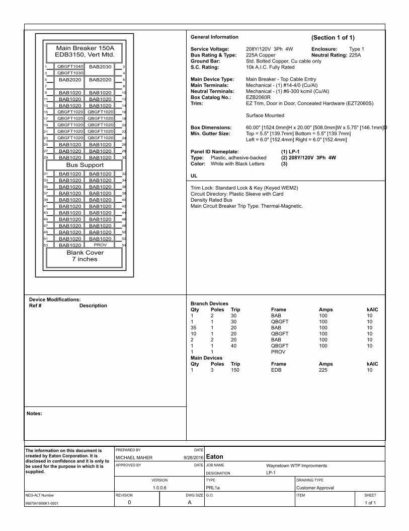
Main Breaker 150AEDB3150, Vert Mtd.
QBGFT1040
QBGFT1030BAB2030
BAB1020 BAB1020BAB1020 BAB1020BAB1020 BAB1020
BAB2020 BAB2020
QBGFT1020 QBGFT1020
QBGFT1020 QBGFT1020
QBGFT1020 QBGFT1020
QBGFT1020 QBGFT1020
QBGFT1020 QBGFT1020
BAB1020 BAB1020BAB1020 BAB1020BAB1020 BAB1020
Bus SupportBAB1020 BAB1020BAB1020 BAB1020BAB1020 BAB1020BAB1020 BAB1020BAB1020 BAB1020BAB1020 BAB1020BAB1020 BAB1020BAB1020 BAB1020BAB1020 BAB1020BAB1020 BAB1020BAB1020 BAB1020BAB1020
Blank Cover7 inches
General Information (Section 1 of 1)
Service Voltage: 208Y/120V 3Ph 4W Enclosure: Type 1Bus Rating & Type: 225A Copper Neutral Rating: 225AGround Bar: Std. Bolted Copper, Cu cable onlyS.C. Rating: 10k A.I.C. Fully Rated
Main Device Type: Main Breaker - Top Cable EntryMain Terminals: Mechanical - (1) #14-4/0 (Cu/Al)Neutral Terminals: Mechanical - (1) #6-300 kcmil (Cu/Al)Box Catalog No.: EZB2060RTrim: EZ Trim, Door in Door, Concealed Hardware (EZT2060S)
Surface Mounted
Box Dimensions: 60.00" [1524.0mm]H x 20.00" [508.0mm]W x 5.75" [146.1mm]DMin. Gutter Size: Top = 5.5" [139.7mm] Bottom = 5.5" [139.7mm]
Left = 6.0" [152.4mm] Right = 6.0" [152.4mm]
Panel ID Nameplate: (1) LP-1Type: Plastic, adhesive-backed (2) 208Y/120V 3Ph 4WColor: White with Black Letters (3)
UL
Trim Lock: Standard Lock & Key (Keyed WEM2)Circuit Directory: Plastic Sleeve with CardDensity Rated BusMain Circuit Breaker Trip Type: Thermal-Magnetic.
Branch DevicesQty Poles Trip Frame Amps kAIC1 2 30 BAB 100 101 1 30 QBGFT 100 1035 1 20 BAB 100 1010 1 20 QBGFT 100 102 2 20 BAB 100 101 1 40 QBGFT 100 101 1 PROVMain DevicesQty Poles Trip Frame Amps kAIC1 3 150 EDB 225 10
Device Modifications:Ref # Description
Notes:
NEG-ALT Number
PREPARED BY DATE
APPROVED BY DATE
VERSION
REVISION DWG SIZE
JOB NAME
DESIGNATION
TYPE
G.O.
DRAWING TYPE
ITEM SHEET
The information on this document is created by Eaton Corporation. It is disclosed in confidence and it is only to be used for the purpose in which it is supplied.
IN870419X6K1-0001
MICHAEL MAHER 9/28/2016
1.0.0.6
0 A
EatonWaynetown WTP ImprovmentsLP-1
PRL1a Customer Approval
1 of 1

Volume 2—Commercial Distribution CA08100003E—April 2014 www.eaton.com V2-T3-7
3
3.3Panelboards and Lighting Control
Pow-R-Line C Panelboards
Pow-R-Line C Panelboards
Product DescriptionLighting and Distribution PanelboardsEaton’s assembled panelboards are designed for sequence phase connection of branch circuit devices. This allows complete flexibility of circuit arrangement (single-, two- or three-pole) to allow balance of the electrical load on each phase.
Sturdy, rigid chassis assembly ensures accurate alignment of interior with panel front; prevents flexing and minimizes possibility of loosening or damage to current carrying parts during and after installation.
Four-point in-and-out adjustment of panel interioris provided to meet critical depth dimensions on flush installations. This compensates for possible misalignment of box at installation.
Main lugs are mechanical solderless type and approved for copper or aluminum conductors.
EnclosuresBoxes are code-gauge galvanized steel, which include a painted box finished in ANSI-61 light gray to match the trim.
Standard panelboard cabinets are designed for indoor use. Alternate types are available for indoor and special purpose applications.
All enclosures are furnished in accordance with Underwriters Laboratories standards and include wiring gutters with proper wire bending space. Special cabinets can be provided at an additional charge.
The box dimensions shown are inside dimensions. For outside dimensions, add 1/4-inch (6.4 mm).
Standard panelboard boxes are supplied without knockouts (blank endwalls).
FrontsFronts (trims) for all panelboards are made of code-gauge steel and have a high durability ANSI-61 light gray finish applied by a baked-on polyester powder coating paint system.
The fronts for lighting and appliance branch circuit panelboards and small power distribution panelboards include a door with rounded corners and concealed hinges. A flush-type latch and lock assembly is included. All locks are keyed alike. These trims are available in both surface- and flush-mounted designs.
EZ Trim Features Standard Door-in-Door with No Exposed Hardware or
Sharp Edges (no Tools are Required for Installation)
The Three-Piece Trim for Larger Power Distribution Panelboards Provides for
Easy Handling and Installation
Fronts for power distribution panelboards utilize a unique breaker front cover design in which each device has a dedicated bolt-on steel cover. The individual covers form a single deadfront for the panelboard that is used in conjunction with two wiring gutter covers to complete the trim. A door is not finished as part of the standard offering on these panelboards but can be provided, for an additional charge, using a deeper than standard box.

V2-T3-8 Volume 2—Commercial Distribution CA08100003E—April 2014 www.eaton.com
3
3.3 Panelboards and Lighting Control
Pow-R-Line C Panelboards
Application DescriptionPanelboard Selection FactorsIn selecting a panelboard, the following factors must be considered:
● Service (voltage andfrequency)
● Interrupting capacity(fully or series rated)
● Ampere rating of main● Ampere ratings of
branches● Environment
Panelboard Short-Circuit RatingThe short-circuit rating of Eaton’s assembled panelboards are test verified by, and listed with, Underwriters Laboratories (UL). Generally, these ratings are that of the lowest interrupting rated device in the panel.
Certain exceptions to this rule exist where branch devices have been UL tested in combination with specific main devices having a higher interrupting rating. Where these defined main devices and branch breaker combinations are utilized, the series short-circuit rating of the assembled panelboard will be the same as the tested rating of the approved rated main device in series with the branches. Available main and branch breaker combinations are tabulated starting on Page V2-T3-16. All combinations shown are UL tested and listed.
These series ratings apply to panels having main devices, or main lug only panelboards fed remotely by the device listed in the series ratings chart as the main, for which UL listed tests were conducted.
Service Entrance EquipmentThe National Electrical Code (NEC) requires that:
● A panel used as serviceentrance equipmentmust be located nearthe point where thesupply conductors enterthe building
● A panelboard having mainlugs only shall have amaximum of six servicedisconnects to de-energizethe entire panelboard fromthe supply conductors.Where more than sixdisconnects are required,a main service disconnectmust be provided
● A disconnectable electricalbond must be providedbetween the neutral andground
● A service entrance typeUL label must be factoryinstalled
● Ground fault protectionof equipment shall beprovided for each servicedisconnect rated 1000Aor more if the electricalservice is a solidlygrounded wye system ofmore than 150V to ground,but not exceeding 600Vphase-to-phase
Note: Service entrance panels must be identified as such on the order.
Panelboard StandardsIn 2008, both the National Electrical Code (Article 408) and UL 67 were updated to remove the mandated 42-circuit limitation. Eaton offers panelboards with more than 42 circuits for those jurisdictions that have adopted the 2008 NEC or later.
For jurisdictions that have| not adopted the 2008 or later version of the National Electrical Code, the 42-circuit limitation for Lighting and Appliance Branch Panelboards remains in place. Check with your local code officials to determine specific jurisdiction status.
Panelboard InstallationNEC requires that the operating handle of the topmost mounted device be no more than 6 feet 7 inches (2006.6 mm) above the finished floor and should be installed per NEC and manufacturer’s instructions.
Additional boxes and fronts are required when the components required for one panelboard exceed the standard box dimensions.
Multi-Section PanelboardsWhen two or more separate enclosures are required, separate fronts for each box are standard. A common front can be furnished at additional charge.
Interconnecting Multi-Section PanelboardsWhen a panelboard, for connection to one feeder, must be furnished in more than one section (Box), each section must be furnished with main bus and terminals of the same rating, unless a main overcurrent device is provided in each section.
Sub-feed or through-feed provisions must also be included (and priced) to provide connection capability to the second section.
Note: Sub-feed or through-feed lugs cannot be used on any panelboard that is not protected by a single main overcurrent device either in the panelboard or immediately upstream, i.e., service entrance panelboards with main lugs only using the six disconnect rule.
Volume 2—Commercial Distribution CA08100003E—April 2014 www.eaton.com V2-T3-9
3
3.3Panelboards and Lighting Control
Pow-R-Line C Panelboards
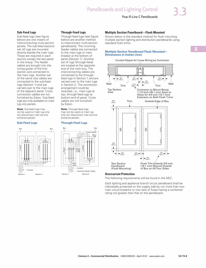
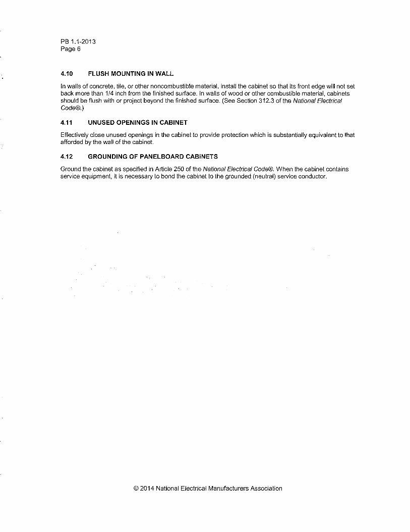
Sub-Feed LugsSub-feed lugs (see figure below) are one means of interconnecting multi-section panels. The sub-feed (second set of) lugs are mounted directly beside the main lugs. These are required in each section except the last panel in the lineup. The feeder cables are brought into the wiring gutter of the first section and connected to the main lugs. Another set of the same size cables are connected to the sub-feed lugs (Section 1) and are carried over to the main lugs of the adjacent panel. Cross connection cables are not furnished by Eaton. Sub-feed lugs are only available on main lug only panels.
Note: Sub-feed lugs may not be used on main lug only (six disconnect rule) service entrance panels.
Sub-Feed Lugs
Through-Feed LugsThrough-feed lugs (see figure below) are another method to interconnect multi-section panelboards. The incoming feeder cables are connected to the main lugs or main breaker at the bottom of panel (Section 1). Another set of lugs (through-feed) are located at the opposite end of the main bus. The interconnecting cables are connected to the through-feed lugs in Section 1 and are carried over to the main lugs in Section 2. The connection arrangement could be reversed, i.e., main lugs at top; through-feed lugs at bottom end of panel. Cross cables are not furnished by Eaton.
Note: Through-feed lugs may not be used on main lug only (six disconnect rule) service entrance panels.
Through-Feed Lugs
Box Box
Conduit
Neutral Neutral
Pan
el
Pan
el
Section 1 Section 2 Section 1 Section 2
Box Box
Conduit
Neutral
Pa
ne
l
Pa
ne
l
Neutral
MainLugs
ThruFeedLugs
MainLugs
Cross Cables
Incoming Feeder Cables
Multiple Section Panelboard—Flush MountedShown below is the standard method for flush mounting multiple section lighting and distribution panelboards using standard flush trims.
Multiple Section Panelboard Flush Mounted—Dimensions in Inches (mm)
Overcurrent ProtectionThe following requirements will be found in the NEC:
Each lighting and appliance branch circuit panelboard shall be individually protected on the supply side by not more than two main circuit breakers or two sets of fuses having a combined rating not greater than that on the panelboard.
Contractor to Mount Boxes1-1/2-inch (38.1 mm) Apart toAllow for 3/4-inch (19.1 mm)Extension on Both Flush Trims
Two SectionPanelboard(Flush Mounting)
Flush Trim Extends 3/4-inch(19.1 mm) Beyond Outsideof Box on All Four Sides
Outside Edge of BoxTrim
Wall WallTrim Trim
Conduit Nipple for Cross Wiring by Contractor
3/4(19.1)
3/4(19.1)
1 1/2(38.1)
Top SectionView
3/4(19.1)
3/4(19.1)
3/4(19.1)
3/4(19.1)
3/4(19.1)
3/4(19.1)
3/4(19.1)
3/4(19.1)
V2-T3-10 Volume 2—Commercial Distribution CA08100003E—April 2014 www.eaton.com
3
3.3 Panelboards and Lighting Control
Pow-R-Line C Panelboards
Branch Circuit Loading for Lighting PanelsThe size of mains and branches should be selected based on the following:
● Motor circuits: NECArticle 430
● Diversity factor● Provision for future loading
Exception Number 1: Individual protection for a lighting panelboard is not required when the panelboard feeder has overcurrent protection not greater than that of the panelboard.
Exception Number 2: For existing installations, individual protection for lighting panelboards is not required where such panelboards are used as service equipment in supplying an individual residential occupancy and where any bus supplying 15 or 20A circuits is protected on the supply side by an overcurrent device.
Ambient TemperaturesThe primary function of an overcurrent device is to protect the conductor and its insulation against overheating. In selecting the size of the devices and conductors, consideration should be given to the ambient temperature surrounding the conductors within and external to the panelboard. Cumulative heating within the panelboard may cause premature operation of the overcurrent protective devices.
Underwriters Laboratories test procedures are based, in part, on 80% loading of panelboard branch circuit devices. The NEC limits the loading of overcurrent devices in panelboards to 80% of rating where in normal operation the load will continue for three hours or more. Further derating may be required, depending on such factors as ambient temperature, duty cycle, frequency or altitude.
Exception: There is one exception to this rule in both UL and NEC. It applies to assemblies and overcurrent devices that have been listed for continuous duty at 100% of its rating.
Special ConditionsStandard panelboards, assembled with standard components, are adequate for most applications. However, special consideration should be given to those required for application under special conditions such as:
● Excessive vibrationor shock
● Frequencies above60 cycles
● Altitudes above 6600 feet(2011.7m)
● Damp environment(possible fungus growth)
● Compliance with federal,state and municipalelectrical codes andstandards
Seismic ConsiderationsThe Uniform Building Code® and the International Building Code, as well as local and state building codes, place an emphasis on seismic building design requirements. Electrical distribution systems are treated as attachments to the building and therefore, fall into this category.
All Eaton panelboards are seismic qualified at the highest possible level, and have been tested in accordance with ANSI C37.81. This standard quantifies actual earthquake conditions, as well as equipment seismic capability.
Harmonic CurrentsStandard panelboard neutrals are rated for 100% of the panelboard current. However, since harmonic currents can cause overheated neutrals, an option is provided for neutrals to be rated at 200% (1200A maximum neutral for 600A main bus) of the panelboard phase current.
Panelboards with the 200% rated neutral are UL listed as suitable for use with non-linear loads.
Prior to specifying the 200% rated neutral, Eaton recommends a harmonic survey be conducted of the distribution system, be it new or existing.
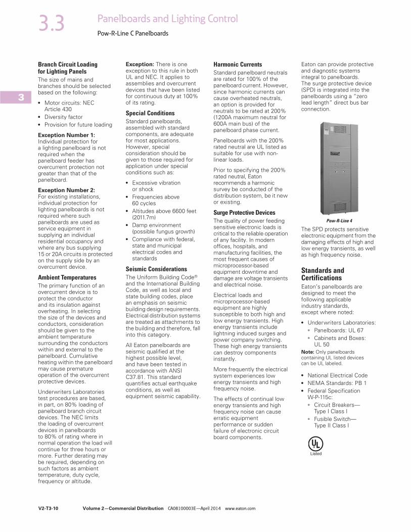
Surge Protective DevicesThe quality of power feeding sensitive electronic loads is critical to the reliable operation of any facility. In modern offices, hospitals, and manufacturing facilities, the most frequent causes of microprocessor-based equipment downtime and damage are voltage transients and electrical noise.
Electrical loads and microprocessor-based equipment are highly susceptible to both high and low energy transients. High energy transients include lightning induced surges and power company switching. These high energy transients can destroy components instantly.
More frequently the electrical system experiences low energy transients and high frequency noise.
The effects of continual low energy transients and high frequency noise can cause erratic equipment performance or sudden failure of electronic circuit board components.
Eaton can provide protective and diagnostic systems integral to panelboards. The surge protective device (SPD) is integrated into the panelboards using a “zero lead length” direct bus bar connection.
Pow-R-Line 4
The SPD protects sensitive electronic equipment from the damaging effects of high and low energy transients, as well as high frequency noise.
Standards and CertificationsEaton’s panelboards are designed to meet the following applicable industry standards, except where noted:
● Underwriters Laboratories:● Panelboards: UL 67● Cabinets and Boxes:
UL 50Note: Only panelboards containing UL listed devices can be UL labeled.
● National Electrical Code● NEMA Standards: PB 1● Federal Specification
W-P-115c:● Circuit Breakers—
Type I Class I● Fusible Switch—
Type II Class I

Volume 2—Commercial Distribution CA08100003E—April 2014 www.eaton.com V2-T3-11
3
3.3Panelboards and Lighting Control
Pow-R-Line C Panelboards
Technical Data and Specifications
Panelboard Selection Guide
Note1 Fixed mounted only.
MaximumVoltage Rating
Maximum MainRating (Amperes)
AC Interrupting Capacityrms Symmetrical Amperes (kA)
PanelboardType
DeviceType AC DC MLO Main Device
Branch CircuitsAmpere Range
Sub-Feed BreakerMaximum Amperes Fully Rated Series Rated
PRL1a Breaker 240 — 400 400 15–100 400 10–22 22–100
PRL1R Breaker 240 — 225 225 15–100 — 10–22 22–100
PRL1aF Fusible 240 — 400 400 15–30 400 200 —
PRL1a-LX Breaker 240 — 225 225 15–100 — 10–22 22–100
PRL2a Breaker 240 250 400 400 15–100 400 65 65–200
Breaker 480Y/277 250 400 400 15–100 400 14 22–150
PRL2R Breaker 240 — 225 225 15–100 — 10–22 22–200
Breaker 480Y/277 — 225 225 15–100 — 14 22–100
PRL2aF Fusible 480Y/277 — 400 400 15–30 400 200 —
PRL2a-LX Breaker 240 250 225 225 15–100 — 65 65–200
Breaker 480Y/277 250 225 225 15–100 — 14 22–150
PRL3a Breaker 240 250 800 600 15–225 600 10–200 22–200
Breaker 480 250 800 600 15–225 600 14–100 22–150
Breaker 600 250 800 600 15–225 600 14–35 —
PRL3E Breaker 240 250 600 600 15–125 400 25–100 100–200
Breaker 480Y/277 250 600 600 15–125 400 18–65 65–100
Breaker 480 250 600 600 15–125 400 18–65 65–100
PRL4B Breaker 240 600 1200 1200 15–1200 — 10–200 22–200
Breaker 480 600 1200 1200 15–1200 — 14–200 22–150
Breaker 600 600 1200 1200 15–1200 — 14–200 —
PRL4D Breaker 240 — 1200 1200 1 600 — 65–200 —
Breaker 480 — 1200 1200 1 600 — 35–100 —
Breaker 600 — 1200 1200 1 600 — 18–50 —
PRL4F Fusible 240 250 1200 1200 30–1200 — 100–200 —
Fusible 600 250 1200 1200 30–1200 — 100–200 —
PRL5P Breaker 240 250 1200 1200 15–1200 — 10–200 22–200
Breaker 480 250 1200 1200 15–1200 — 14–200 22–150
Breaker 600 250 1200 1200 15–1200 — 14–200 —
PRC100 PRC25 Breaker 240 — 400 400 15–225 — 10–65 22–100
Breaker 480Y/277 — 400 400 15–225 — 14 65–100
Elevator Control Fusible 240 — 800 800 15–200 — 200 —
Fusible 480Y/277 — 800 800 15–200 — 200 —
Fusible 480 — 800 800 15–200 — 200 —
Terminal Wire Ranges, Pressure-Type Al/Cu Terminals Except as NotedNote: All terminal sizes are based on wire ampacities corresponding to those shown in NEC Table 310.16 under the 75°C insulation columns (75°C wire). The use of smaller size, (in circular mills), regardless of insulation temperature rating, is not permitted.
Where copper-aluminum terminals are supplied on designated panelboard types, best results are obtained if a suitable joint compound is applied when aluminum conductors are used.
Check Eaton’s standard terminal sizes versus customer requirements. In particular, 400 and 800A breakers often require nonstandard lugs.
Optional 750 kcmil mechanical screw-type terminals are available upon request. Panelboard dimensions may be affected, refer to Eaton.

Volume 2—Commercial Distribution CA08100003E—April 2014 www.eaton.com V2-T3-13
3
3.3Panelboards and Lighting Control
Pow-R-Line C Panelboards
Standard Circuit Breaker Terminals
Breaker Type Ampere Rating Wire Range
BAB, QBHW, BABRSP,HQP, QPHW
15–70 #14–#4
90–100 #8–1/0
EDB, EDS, ED, EDH, EDC 100–225 #4–4/0 or #6–300 kcmil
EGB, EGE, EGS, EGH 15–50 #14–3/0 AL/CU
60–125 #6–3/0 AL/CU
EHD, FDB, FD, HFD, FDC, HFDDC 2
15–100 #14–1/0
125–225 #4–4/0
FCL 15–100 #14–1/0
GHB, HGHB, GHQ, GHQRSP
15–20 #14–#10
25–100 #10–1/0
EGB, EGS, EGH 15–50 #14–1/0
60–125 #6–2/0
JD, HJD, JDC, HJDDC 2 70–250 #4–350 kcmil
DK 250–350 250–500 kcmil
400 (2) 3/0–250 kcmil or (1) 3/0–500 kcmil
KD, HKD, KDC, HKDDC, 2CKD, CHKD
225 (1) #3–350 kcmil
350 (2) 3/0–250 kcmil or
400 (2) 3/0–250 kcmil or (1) 3/0–500 kcmil
LHH 150–400 #2–500 kcmil
150–400 (2) #2–500 kcmil
150–400 (1) 500–750 kcmil
LGE, LGH, LGC, LGU, LHH 1
250–400 (1) #2–500 kcmil
500–600 (2) #2–500 kcmil
LD, HLD, LDC, HLDDC 2CLD, CHLD
300–500 (2) 250–350 kcmil
600 (2) 400–500 kcmil
MDL, HMDL, HMDLDC 2CMDL, CHMDL
400–600 (2) #1–500 kcmil
700–800 (3) 3/0–400 kcmil
ND, HND, CND, CHND, NDC, CNDC
800–1000 (3) 3/0–400 kcmil
1200 (4) 4/0–500 kcmil
LCL 125–225 (1) #6–350 kcmil
250–400 (1) #4–250 kcmil and (1) 3/0–600 kcmil
FB-P 15–100 #14–1/0
LA-P 70–225 #6–350 kcmil
250–400 (1) #4–250 kcmil and (1) 3/0–600 kcmil
NB-P, NBDC 2 300–700 (2) #1–500 kcmil
800 (3) 3/0–400 kcmil
FDPW Switch Terminals
Elevator Control Panel Feeder Terminals
Notes1 LHH is 400A maximum.2 Suitable for DC applications only.
Ampere Rating Wire Range
30 #14–1/0
60 #14–1/0
100 #14–1/0
200 #4–300 kcmil
400 250–750 kcmil or (2) 3/0–250 kcmil
600 (2) #4–600 kcmil or (4) 3/0–250 kcmil
800 (3) 250–750 kcmil or (6) 3/0–250 kcmil
1200 (4) 250–750 kcmil or (8) 3/0–250 kcmil
Ampere Rating Wire Range
30 #14–1/0
60 #14–1/0
100 #14–1/0
200 #4–300 kcmil


![Basics of Switchboards[1]](https://static.fdocuments.in/doc/165x107/55cf9a6b550346d033a1a0f3/basics-of-switchboards1.jpg)