ATT-TP-76416 Grounding and Bonding Requirements for ... · 1.8.3 Application Of Lock Washers For...
161
© 2004-2005 AT&T Knowledge Ventures All rights reserved.. 1 ATT-TP-76416 Grounding and Bonding Requirements for Network Facilities This Practice provides engineering, material, and installation requirements for grounding systems in network facilities containing communications systems and other equipment. Audience: All network employees Effective Date: 2/01/2004 Issue Date: Issue 1, 02/01/2004 Expires On: NA Related Documents: ATT-TP-76416-001 (Grounding and Bonding for Network Facilities – Design Fundamentals) Cancelled Documents: ATT-812-000-027, ATT-812-000-028 Issuing Department: NP & E, Enterprise Technology Support – Common Systems Business Unit: AT&T Services, Inc. Author(s): Chuck Slavin, Telephone: 775-333-3948; SBCUID: cs2416 INTRODUCTION This Practice provides engineering, material, and installation requirements for protective grounding systems in structures containing network communications systems and other equipment. This document was previously numbered SBC-812-000-027, Issue 0, May 2003. REASON FOR REISSUE Issue Date Description of Changes Author 1 02/01/2004 a) Convert SBC 812-000-027 to TP format; b) miscellaneous clarifications, revisions and additions as summarized in Annex B. CS2416
Transcript of ATT-TP-76416 Grounding and Bonding Requirements for ... · 1.8.3 Application Of Lock Washers For...

© 2004-2005 AT&T Knowledge Ventures All rights reserved.. 1
ATT-TP-76416
Grounding and Bonding Requirements for Network Facilities
This Practice provides engineering, material, and installation requirements for grounding systems in network facilities containing communications systems and other equipment.
Audience: All network employees
Effective Date: 2/01/2004
Issue Date: Issue 1, 02/01/2004
Expires On: NA
Related Documents: ATT-TP-76416-001 (Grounding and Bonding for Network Facilities – Design Fundamentals)
Cancelled Documents: ATT-812-000-027, ATT-812-000-028
Issuing Department: NP & E, Enterprise Technology Support – Common Systems
Business Unit: AT&T Services, Inc.
Author(s): Chuck Slavin, Telephone: 775-333-3948; SBCUID: cs2416
INTRODUCTION This Practice provides engineering, material, and installation requirements for protective grounding systems in structures containing network communications systems and other equipment. This document was previously numbered SBC-812-000-027, Issue 0, May 2003.
REASON FOR REISSUE Issue Date Description of Changes Author
1 02/01/2004 a) Convert SBC 812-000-027 to TP format; b) miscellaneous clarifications, revisions and additions as summarized in Annex B.
CS2416

© 2004-2005 AT&T Knowledge Ventures All rights reserved.. 2
SECTION 1 Definitions, General and Material Requirements
1.1 SCOPE ..................................................................................................................................7 1.2 GENERAL .............................................................................................................................7 1.3 DEFINITIONS AND ACRONYMS .........................................................................................7 1.4 GROUND RODS ..................................................................................................................13
1.4.1 Construction .............................................................................................................13 1.4.2 Dimensions ...............................................................................................................13
1.5 CONDUCTORS ...................................................................................................................13 1.5.1 Exterior Buried Conductors ....................................................................................13 1.5.2 Equipment Grounding Conductors ........................................................................14 1.5.3 AC Equipment Ground (ACEG) Conductor ...........................................................14 1.5.4 Grounding Conductors Within Equipment Bays ..................................................14 1.5.5 Grounding Conductor Color ...................................................................................14
1.6 CONNECTORS & CONDUIT BONDING DEVICES ............................................................15 1.6.1 Exothermic Welding ................................................................................................15 1.6.2 Clamp Type Pipe Connectors and Conduit Bonding Devices .............................16 1.6.3 Crimp (Compression) Connectors .........................................................................16 1.6.4 Pressure Type (Mechanical) Connectors ..............................................................17 1.6.5 Parallel Cable Connectors ......................................................................................17 1.6.6 Miscellaneous Connectors .....................................................................................17 1.6.7 Solder-Type Connectors .........................................................................................18
1.7 BUS BARS ..........................................................................................................................18 1.7.1 Construction .............................................................................................................19 1.7.2 Dimensions ...............................................................................................................19
1.8 INSTALLATION REQUIREMENTS .....................................................................................19 1.8.1 General Requirements - Routing and Supporting Conductors ...........................19 1.8.2 Connecting and Identifying Conductors ...............................................................21 1.8.3 Application Of Lock Washers For Grounding Connections ................................22
SECTION 2 Office Ground Electrodes, Vertical and Horizontal Equalizers, AC Service and Distribution System
2.1 SCOPE ................................................................................................................................25 2.2 EARTH ELECTRODES .......................................................................................................25
2.2.1 Public and Private Water Systems .........................................................................25 2.2.2 Water Well Metallic Casing .....................................................................................25 2.2.3 Driven Ground Electrodes ......................................................................................26 2.2.4 Other Electrodes ......................................................................................................30 2.2.5 Interbonding of Earth Electrodes ...........................................................................31
2.3 DRIVEN GROUND SYSTEM FOR RADIO SITES ..............................................................31 2.4 CENTRAL OFFICE GROUND SYSTEM .............................................................................31
2.4.1 Office Principal Ground Point (OPGP) ...................................................................32 2.4.2 Interbonding .............................................................................................................34 2.4.3 Design Parameters - Vertical Riser ........................................................................35 2.4.4 Design Parameters - Horizontal Equalizer System ...............................................40 2.4.5 CO Ground Bus Bars ...............................................................................................41 2.4.6 Designation of OPGP & CO Ground Bus Bars ......................................................41 2.4.7 Office Drawings ........................................................................................................42

© 2004-2005 AT&T Knowledge Ventures All rights reserved.. 3
2.5 ROUTING AND SUPPORT OF EQUALIZER CONDUCTORS ...........................................42 2.6 BUILDING ENGINEERING .................................................................................................42 2.7 AC SYSTEM GROUNDING .................................................................................................43
2.7.1 Grounding Electrode Conductor (GEC) .................................................................43 2.7.2 Main Bonding Jumper .............................................................................................44 2.7.3 Gounding of Separately Derived AC Systems ......................................................44
2.8 AC EQUIPMENT GROUNDING ..........................................................................................45 2.8.1 Feeder and Branch Circuit Equipment Grounding System .................................45 2.8.3 AC Power Distribution Cabinets .............................................................................48 2.8.4 AC Bus Duct System ...............................................................................................48 2.8.5 Engine-Alternator Sets ............................................................................................49 2.8.6 Grounding of AC Tap Boxes ...................................................................................49 2.8.7 Cord Connected AC Operated Equipment ............................................................50 2.8.8 Job Drawings, Architectural ...................................................................................50 2.8.9 Rooftop Facilities .....................................................................................................51
2.9 COORDINATION WITH CORPORATE REAL ESTATE .....................................................51
SECTION 3 Power Plants and Equipment, Transport
and Miscellaneous Equipment 3.1 SCOPE ................................................................................................................................54 3.2 GENERAL ...........................................................................................................................54
3.2.1 An Overview of Power and Grounding Systems ..................................................54 3.3 DC POWER SYSTEMS .......................................................................................................55
3.3.1 Battery and Converter Plants, DC-DC Converters ................................................55 3.3.2 140-Volt Power Plant and Distribution System .....................................................57 3.3.3 Power System Equipment Grounding ...................................................................58 3.3.4 Engine Alternator Equipment .................................................................................59
3.4 POWER DISTRIBUTION SYSTEMS ...................................................................................61 3.4.1 Battery Distributing Fuse Board (BDFB) ...............................................................62 3.4.2 Fuse Boards (F BD) .................................................................................................63
3.5 TRANSPORT, INFORMATION TECHNOLOGY AND MISCELLANEOUS EQUIPMENT ..64 3.5.1 Equipment Enclosure and Unit Requirements ......................................................65 3.5.2 Lineup Conductors ..................................................................................................66 3.5.3.Bonds to Ironwork and Other Metallic Objects .....................................................67 3.5.4 Other Systems ..........................................................................................................68 3.5.5 Bay Ground Lead .....................................................................................................68 3.5.6 Conduits, Armored Cable, Shielded Wire for Other Than AC Service ................69
3.6 DISTRIBUTING AND PROTECTOR FRAMES ...................................................................69 3.7 CABLE ENTRANCE FACILITY (CEF) ................................................................................70 3.8 CABLE REARRANGEMENT FACILITY .............................................................................71 3.9 FIBER OPTIC CABLE TERMINATION EQUIPMENT .........................................................71 3.10 NETWORK EQUIPMENT ON RAISED FLOORS .............................................................73
3.10.1 General ....................................................................................................................73 3.10.2 Horizontal Equalizer Conductor ...........................................................................74 3.10.3 Isolated Bonding Network Equipment .................................................................74 3.10.4 Common Bonding Network Equipment ...............................................................75 3.10.5 Cable Rack Bonds .................................................................................................76 3.10.6 Power Plant Area Grounding & Bonding .............................................................77 3.10.7 Bonds to Other Metallic Objects ..........................................................................78

© 2004-2005 AT&T Knowledge Ventures All rights reserved.. 4
3.10.8 Routing and Securing Grounding Conductors ...................................................78
SECTION 4 Isolated Bonding Networks for Network Equipment Systems,
Data Processing/Operational Support Systems Equipment 4.1 SCOPE ................................................................................................................................79 4.2 GENERAL ...........................................................................................................................79 4.3 TERMINOLOGY AND CONCEPTS ....................................................................................79
4.3.1 Single Point Ground ................................................................................................79 4.3.2 Isolated Ground .......................................................................................................80 4.3.3 Isolated Bonding Network .......................................................................................80 4.3.4 Ground Window .......................................................................................................80
4.4 MAIN GROUND BUS (MGB) ..............................................................................................82 4.4.1 Common Requirements ..........................................................................................83 4.4.2 Connection to CO Ground ......................................................................................83
4.5 MAIN GROUND BUS LOCATIONS ....................................................................................84 4.5.1 MGB Located in the Equipment Area .....................................................................84 4.5.2 MGB at Power Plant with Insulated Return Bus ...................................................84 4.5.3 MGB at Power Plant with Un-insulated Return Bus .............................................86 4.5.4 Sequencing ...............................................................................................................87 4.5.5 Remote MGB ............................................................................................................88 4.5.6 Supplementary MGB ................................................................................................89 4.5.7 Relocating an Existing MGB ...................................................................................89
4.6 BONDS TO THE MAIN GROUND BUS ..............................................................................90 4.6.1 Conduits, Raceways, and Other Conductive Paths ..............................................90 4.6.2 Lighting System Components ................................................................................92 4.6.3 Foreign Object Bonds .............................................................................................92 4.6.4 Protector Frame Bonds ...........................................................................................95
4.7 ISOLATED BONDING NETWORK EQUIPMENT ...............................................................95 4.7.1 Framework Ground Systems ..................................................................................95 4.7.2 Logic Ground Systems ............................................................................................96 4.7.3 Other Ground Systems ............................................................................................97 4.7.4 Battery Return Systems ..........................................................................................97 4.7.5 Equipment Separation and Circuit Location .........................................................97 4.7.6 Insulation ..................................................................................................................99 4.7.7 Lucent 5ESS Standard ............................................................................................99 4.7.8 Nortel DMS Standard .............................................................................................101
4.8 POWER PLANTS ..............................................................................................................103 4.8.1 Power Plant Location ............................................................................................103 4.8.2 Power Plants Serving Common and Isolated Bonding Network Equipment ...103 4.8.3 Different Isolated Bonding Networks Served by the Same Power Plant ..........105
4.9 COMPUTER EQUIPMENT - GENERAL ...........................................................................105 4.9.1 Background ............................................................................................................105 4.9.2 Application of this section and Other Documents .............................................105 4.9.3 Characteristics of Computer Grounding and Power Arrangements .................106
4.10 COMPUTER EQUIPMENT - COMMON REQUIREMENTS ............................................106 4.10.1 Bond to Structure's Ground System ..................................................................106 4.10.2 AC Equipment Grounding (ACEG) System .......................................................107 4.10.3 Isolated Bonding Network Requirements ..........................................................107 4.10.4 Special Note on Isolated Ground Type Receptacles ........................................108
4.11 COMPUTER EQUIPMENT - POWER AND GROUNDING .............................................108

© 2004-2005 AT&T Knowledge Ventures All rights reserved.. 5
4.11.1 AC Power Distribution Equipment .....................................................................108 4.11.2 Powered From Distribution Panel(s) ..................................................................109 4.11.3 Powered From One PDU .....................................................................................109 4.11.4 Powered From Multiple PDUs .............................................................................109 4.11.5 Isolated Ground Type Receptacles Required ...................................................110 4.11.6 Standard Receptacles Used ................................................................................110 4.11.7 DC-Powered Equipment ......................................................................................110
4.12 COMPUTER EQUIPMENT - MISCELLANEOUS REQUIREMENTS ..............................110 4.12.1 Raised Floor Applications ...................................................................................110 4.12.2 System Testing ....................................................................................................111 4.12.3 Peripheral Equipment ..........................................................................................112
SECTION 5 Electronic Equipment Enclosures, Attended Position Equipment,
Equipment Trailers, Customer Premises Equipment 5.1 SCOPE ..............................................................................................................................113 5.2 ELECTRONIC EQUIPMENT ENCLOSURES ...................................................................113
5.2.1 Principal Ground Point ..........................................................................................113 5.2.2 Earth Electrode Systems .......................................................................................113 5.2.3 AC Service Grounding ...........................................................................................115 5.2.4 Additional Considerations ....................................................................................117 5.2.5 Grounding Conductor Placement and Sizes .......................................................118 5.2.6 DC Power System and Equipment Grounding ....................................................118 5.2.7 Requirements in Other Sections ..........................................................................119
5.3 ATTENDED POSITION EQUIPMENT ...............................................................................119 5.3.1 Position Bonding Grid System .............................................................................120 5.3.2 Miscellaneous Requirements ...............................................................................121
5.4 EQUIPMENT TRAILERS ...................................................................................................122 5.4.1 General ....................................................................................................................122 5.4.2 Requirements .........................................................................................................122
5.5 CUSTOMER PREMISES EQUIPMENT ............................................................................124 5.5.1 General ....................................................................................................................124 5.5.2 Access to a Site's Earth Electrode System .........................................................124 5.5.3 Customer's Equipment Grounding System .........................................................125 5.5.4 Cable Entrance ......................................................................................................127 5.5.5 DC Power Systems Provided with Network Equipment .....................................128 5.5.6 Power System(s) Provided by Customer .............................................................129 5.5.7 Grounding and Bonding Within Frames, Cabinets & Enclosures......................129
SECTION 6 Radio Sites and Equipment
6.1 SCOPE ..............................................................................................................................131 6.2 GENERAL .........................................................................................................................131 6.3 EXTERIOR RING GROUND SYSTEM ..............................................................................132
6.3.1 Earth Electrode System .........................................................................................132 6.3.2 Roof Ring Ground System ....................................................................................133 6.3.3 Interior-Exterior Bonds ..........................................................................................134 6.3.4 Bonds to Antenna Towers ....................................................................................134
6.4 INTERIOR RING GROUND SYSTEM ...............................................................................135 6.4.1 Peripheral Conductor ............................................................................................135

© 2004-2005 AT&T Knowledge Ventures All rights reserved.. 6
6.4.2 Supplementary Conductors ..................................................................................137 6.4.3 Waveguide and Coaxial Cable Bonds ..................................................................139
6.5 UNIT BONDS .....................................................................................................................139 6.5.1 Exterior Unit Bonds ...............................................................................................139 6.5.2 Interior Unit Bonds ................................................................................................140 6.5.3 Frame/Cabinet Bonding Requirements ...............................................................141 6.5.4 Miscellaneous Unit Bonding .................................................................................142 6.5.5 Conduit, Pipe and Duct Bonding ..........................................................................142 6.5.6 Bonding of Units Outside the Ring Ground Periphery .......................................143
6.6 BONDS AT STRUCTURE ENTRANCES ..........................................................................143 6.6.1 General ....................................................................................................................144 6.6.2 Auxiliary Bus Bar ...................................................................................................144 6.6.3 Other Arrangements ..............................................................................................145 6.6.4 Exterior Bonds .......................................................................................................145 6.6.5 Interior Bonds ........................................................................................................147
6.7 BONDING OF STRUCTURAL MEMBERS .......................................................................148 6.8 SMALL RADIO/ANTENNA SYSTEMS .............................................................................149
6.8.1 Scope ......................................................................................................................149 6.8.2 System Component Location and Other Considerations ..................................149 6.8.3 Down Conductors ..................................................................................................150 6.8.4 Pole-Mounted Antennas ........................................................................................151 6.8.5 Bonding Conductors .............................................................................................152
6.9 MATERIAL ........................................................................................................................152 6.9.1 Protective Devices .................................................................................................152 6.9.2 Conductors .............................................................................................................152 6.9.3 Connectors .............................................................................................................153 6.9.4 Other Material .........................................................................................................153
ANNEX A Reference Documents and Information ...........................................................154 ANNEX B Revisions to Text and Figures ..........................................................................159 ANNEX C Index to Figure and Tables ...............................................................................160

© 2004-2005 AT&T Knowledge Ventures All rights reserved.. 7
SECTION 1 Definitions, General and Material Requirements
1.1 SCOPE This Practice provides engineering, material, and installation requirements for protective grounding systems in structures containing network communications systems and other equipment. This document was previously numbered SBC-812-000-027 and is no longer a proprietary document. 1.2 GENERAL
1) The requirements in this Practice replace all associated grounding and bonding requirements in all previous Practices, Memorandums, Engineering Letters, Technical Publications, and other documents used by every AT&T Local Exchange Carrier (LEC), with the exception of Southern New England Telephone, prior to the date of this Practice. See Annex A, References, for a list of Practices and other documents replaced by this Practice.
Note: For AT&T LEC employees, Southern New England Telephone central office grounding and bonding requirements are provided in: SNE-J98022-71, SNET Building Ground System SNE-T98023-31, Building Ground & Equipment Ground System
2) Several documents in Annex A were the source of many of the requirements in this Practice. Several were also the source of grounding fundamentals used to develop requirements not originally contained in these documents. 3) See Annex B for a list of revisions to Issue B of this Practice. 4) Requirements in this Practice will not cover every unique application that may be encountered. A grounding arrangement may be devised and used for a specific application based on design criteria provided in this Practice. This can be especially important when assessing the need for upgrades to an existing grounding arrangement. 5) Where applicable, the requirements in this Practice conform to or exceed the requirements in NFPA 70, National Electrical Code (NEC). 6) Where specific grounding requirements are included in the specifications of approved equipment, they shall have precedence over the general requirements of this Practice. Where specific grounding requirements are not furnished in system specifications or have not been updated to the requirements contained in this Practice, a grounding system meeting the requirements of this Practice shall be provided.
1.3 DEFINITIONS AND ACRONYMS The following terms are used throughout this Practice. The terms marked with an asterisk (*) are consistent with the NEC and include the text from Article 100 of the NEC. Table 1-1 is located at the end of this section on definitions. It contains a cross-reference between grounding and bonding terms used in this Practice and equivalent terms used by standards bodies, equipment vendors and others. Network acronyms can be found in ATT-000-000-020, Network Acronyms Dictionary. Ac Alternating Current ACEG Alternating Current Equipment Ground AG/EEE Above Ground Electronic Equipment Enclosure AWG American Wire Gauge

© 2004-2005 AT&T Knowledge Ventures All rights reserved.. 8
BDB Battery Distribution Board BDCBB Battery Distribution Circuit Breaker Board BDFB Battery Distribution Fuse Board BG/EEE Below Ground Electronic Equipment Enclosure Battery Return – The battery return is one of two wires (the other is generally called “battery”) used to provide dc power to network equipment. The battery return wire is grounded to the CO GRD System via the battery return bus bar. *Bonding - The permanent joining of metallic sub-sections to form an electrically conductive path, which will assure electrical continuity and the capacity to conduct safely any current likely to be imposed. BSP Bell System/Service Practice CBN Common Bonding Network CDF Combined Distributing Frame CEF Cable Entrance Facility Central Office Ground (CO GRD) - The grounding system within a structure, including the Office Principal Ground Point (OPGP), the Vertical Riser, horizontal equalizers, CO GRD bus bars on each floor, the connections to ac and dc power systems, and the connections to equipment and other objects. The CO GRD system is often referred to as a tree since, in multifloor applications, the vertical conductors resemble a trunk and the horizontal conductors resemble branches extending from the trunk. This system is designed to:
1) Provide a fault current return path that permits effective operation of over current protective devices
2) Provide a low impedance reference to the building's principal ground point 3) Allow an interchange of ground currents to effectively maintain equal potential in communication circuits
Central Office Ground Bus Bar - A bus bar that references the principal ground point through the Vertical Riser. At least one of these bus bars is provided on each floor to permit the grounding of frames and power supplies, as required. Choke - A metallic support that completely encircles a ground wire thereby increasing the inductive properties of the wire. Also known as “girdle”. Common Bonding Network (CBN) - A set of interconnected objects that has one or more connections to a ground reference. This network, created by a multitude of connections, helps to ensure that the objects are at essentially the same potential when fault current flows through them. Building steel, water pipes, vertical and horizontal equalizer conductors, metallic raceways, raised floor systems, equipment frames and other conductive objects form a common bonding network when bonded together by intentional and incidental connections. This term is now used throughout this Practice in place of integrated ground plane. CRF Cable Rearrangement Facility DC System Grounding Conductor - The conductor used to connect one side of a dc power source to the site's grounding system. Example: In a -48 volt battery-type power plant serving central office equipment, the conductor between the positive (+) side of the plant and a point on the CO GRD system.

© 2004-2005 AT&T Knowledge Ventures All rights reserved.. 9
Daisy Chaining - Daisy chaining is the unacceptable practice of extending a grounding connection by using the conductive mass of two or more components bonded together (rather than using the acceptable method of installing a separate, dedicated grounding wire that has bonds to each of the components. Direct Current Equipment Grounding (DCEG) Conductor - The conductor that bonds an equipment frame, cabinet or other enclosure to the CO GRD system. The DCEG conductor may also bond an equipment unit within a frame, cabinet or other enclosure to the CO GRD system. “DCEG conductor” is now used in place of framework grounding conductor. Driven Ground Electrode For company locations, this means a driven ground rod. Other publications may use the term made electrodes, which includes plate, pipe, or other electrode designs that may not be approved for use at central offices and other company structures. EEE Electronic Equipment Enclosure EMT Electrical Metallic Tubing EQPT Equipment Equalization - The process of connecting different ground reference sources together with an objective of providing a single ground reference. Equipment Ground (EG) - Deliberately engineered conductors in communication systems and ac and dc power distribution systems to provide electrical paths of sufficient capacity to permit protective devices (e.g. fuses, circuit breakers) to operate effectively and to equalize potential between equipment. Exothermic Weld - A mixture of aluminum, copper oxide and other powders are held in place with a graphite mold around the joint to be treated. The mixture is ignited and the heat generated (in excess of 40000 F) is sufficient to boil away contaminating films and foreign substances while joining the pieces with a continuous metallic bridge with electrical and mechanical properties similar to the individual items joined. Proprietary names include Cadweld and Thermoweld. Flash Over - An unintended electric discharge. Framework Ground (FRWK GRD) - That portion of the grounding system that provides a connection between the CO GRD system and frames, cabinets and metallic objects. GEC Grounding Electrode Conductor *Ground (GRD, GND) - A conducting connection, whether intentional or accidental, between an electrical circuit or equipment and the earth, or to some conducting body that serves in place of the earth. Ground Fault - A conducting connection, whether intentional or accidental, between any of the conductors of an electrical system and the grounding conductor or conducting material which encloses the conductors (such as conduit) or any conducting material that is grounded or that may become grounded. *Grounded - Connected to the earth or to some conducting body that serves in place of the earth. *Grounded Conductor - A system or circuit conductor that is intentionally grounded. Example: The conductor usually referred to as the grounded conductor is the neutral conductor in ac circuits and the battery return conductor in dc circuits.

© 2004-2005 AT&T Knowledge Ventures All rights reserved.. 10
*Grounding Conductor - A conductor used to connect equipment or the grounded circuit of a wiring system to a grounding electrode or electrodes. Example: The alternating current equipment ground (ACEG), also called the green wire, used to provide a fault current return path in ac power systems or the grounding conductors used to interconnect frames, aisle grounds, horizontal equalizers, and vertical equalizers. Grounding Electrode - A conductor (usually buried) for the purpose of providing an electrical connection to ground. *Grounding Electrode Conductor (GEC) - The conductor used to connect the grounding electrode to the equipment grounding conductor and/or to the grounded conductor of the circuit at the service equipment or at the source of a separately derived system. Example: In the ac service entrance switchgear of a building, the conductor between the insulated neutral bus bar and the office principal ground point bus bar. Grounding Electrode System - An arrangement of intentionally bonded objects that furnish reference to earth and consist of one or all of the following:
a) Specifically designed metallic objects such as driven ground rods, well casings, or other approved electrodes; b) Grounding electrodes of other systems (e.g., ac power, lightning protection); c) Most buried metallic objects that enter any portion of a structure
Ground Window (GW) - An imaginary spherical volume having a radius of 3 feet. This transition area contains the main ground bus (MGB), which is the physical interface between the building's common bonding network and isolated bonding network equipment. The Ground Window is the opening where grounding conductors serving isolated bonding network equipment are connected to the common bonding network. Horizontal Equalizers Conductors of relatively low impedance (usually 750kcm) that interconnect: a) Vertical Risers in a building that is of a size that requires more than one Vertical Riser b) The CO GRD bus bar to equipment areas on the same floor c) Battery return bus bars in dc distribution systems for some electronic switching systems d) A horizontal equalizer conductor to an equipment unit or area on the same floor e) BDFB bus bars (non-insulated) to the CO GRD HSP House Service Panel IBN Isolated Bonding Network IDF Intermediate Distributing Frame IMC Intermediate Metal Conduit Incidental Ground - Ground paths that exist within a building through contact between such items as structural steel, water piping, air ducts, conduits, superstructure, raceways, reinforcement rod, cable racks, and other conductive objects that are primarily installed for other purposes but secondarily provide an electrical path to ground. Integrated Ground Plane (See Common Bonding Network) Isolated Bonding Network (IBN) - A set of interconnected objects that is referenced to ground at a single point. This network is insulated from contact with any other conductive member not part of the same bonding network. With only one point of ground reference, the possibility that the equipment will be used as a conductive path for transient currents from exterior sources is greatly reduced. This term is now used throughout this Practice in place of isolated ground plane.

© 2004-2005 AT&T Knowledge Ventures All rights reserved.. 11
Isolated Ground Plane (See Isolated Bonding Network) Isolated Ground Zone (Same as Isolated Bonding Network) Isolated Return Bar - This is a bus bar used when a power plant serves Isolated Bonding Network equipment but does not have its battery return bus bar insulated from the framework of the power plant. It consists of either a bus bar detail or a separate bus bar. When this is a bus bar detail, one end is mounted on an insulator and the other is bolted to the existing battery return bus bar. When it is a separate bus bar, both ends are mounted on insulators and at least one 750 kcmil conductor ties this isolated bar back to the battery return bus bar. kcmil 1,000 Circular Mils *Listed - Equipment or materials included in a list published by an organization acceptable to the authority having jurisdiction and concerned with product evaluation, that maintains periodic inspection of production of listed equipment or materials, and whose listing states either that the equipment or material meets appropriate designated standards or has been tested and found suitable for use in a specified manner. LPCDF Low Profile Combined Distributing Frame *Main Bonding Jumper - The connection between the grounded circuit conductor and the equipment grounding conductor at the service. Main Ground Bus (MGB) - A bus bar located within the ground window that provides a physical means of connection between the CO GRD system and the isolated bonding network served by the ground window. MCM 1,000 Circular Mils (old term; see kcmil) MDF Main Distributing Frame MTCE Maintenance NEC National Electrical Code NRTL Nationally Recognized Testing Laboratory Neutral - In ac power distribution, the conductor that is intentionally grounded on the supply side of the service disconnect and provides a current return path for ac power currents. Office Principal Ground Point (OPGP) - A bus bar normally located near the ac entrance switchgear. It functions as:
a) The connection point for all main grounding conductors and earth electrodes; b) The point of origin for the Vertical Riser; c) If convenient, the CO GRD bus bar for the floor (typically the basement) where it is located
PBD Power Board PBSD Pacific Bell Standard Drawing PCF Power Control and Fuse Distribution PD Power Distribution PDC Power Distribution and Control PDU Power Distribution Unit PGP Principal Ground Point Plating - A coating of silver, nickel or tin that is applied to copper conductors to inhibit oxidation of the copper. Tin is the least expensive of these coatings and most widely used.

© 2004-2005 AT&T Knowledge Ventures All rights reserved.. 12
*Premises Wiring (as applied to a System) - That interior and exterior wiring, including power, lighting, control and signal circuit wiring together with all of its associated hardware, fittings, and wiring devices, both permanently and temporarily installed, which extends from the load end of the service drop or load end of the service lateral conductors, or source of a separately derived system to the outlet(s). Such wiring does not include wiring internal to appliances, fixtures, motors, controllers, motor control centers, and similar equipment. *Raceway - An enclosed channel designed expressly for holding wires, cables, or bus bars, with additional functions as permitted in the National Electrical Code (NEC). Radial Grounding - Most often associated with IBN installations of switches. Equipment frames are connected in sub groups with each frame of a sub group bonded to a single grounding conductor. These grounding conductors are connected to the MGB resulting in a number of grounding radials emanating from the MGB to sub groups of equipment frames. Also see Serial Grounding. Relay Rack Ground (RR GRD) - An early practice that used a bus bar at the top of a frame as both a battery return conductor and a means to ground the frame. Ring Ground (for earth electrodes) - A buried conductor that forms a ring around a structure. The ring ground usually includes a series of driven ground rods bonded to the conductor. SBGL Stranded Bay Ground Lead Separately Derived Source - A power source that has no direct electrical connection, including a solidly connected grounded circuit conductor, to supply conductors originating in another system. This definition is similar to the NEC definition of Separately Derived Systems. Example: A standby ac reserve arranged so that the neutral is switched or power supplies with isolation between input and output such as most delta-wye transformers and some inverters and converters. Serial Grounding - Most often associated with IBN installations of switches. Each frame of a subgroup of frames is bonded to a single, common grounding conductor that, in turn, is extended and bonded to other subgroups of frames or to the MGB. Also see Radial Grounding. Single Point Ground - A method used to ground a circuit at only one physical point. It is important to note that “point” in this context actually refers to an area on a bus bar from which a common ground reference is obtained. It is a single point (area) for obtaining ground reference but there may be multiple conductors that terminate at this point for ground reference. Solidly Grounded - A method of grounding either a power supply or a frame that uses a grounding conductor connection in which no additional impedance has been intentionally connected in series with the grounding path. UL Underwriters Laboratories Vertical Riser (VR) - This conductor, also called the Vertical Equalizer, extends ground reference from the OPGP to one or more CO GRD bus bars on each floor of the structure. The portion of this conductor that is routed horizontally between the OPGP and the first connection to a CO GRD bus bar is also called the vertical riser. Withstand Rating - The maximum current an unprotected (no over current device) electrical component can sustain for a specified period of time without the occurrence of extensive damage.

© 2004-2005 AT&T Knowledge Ventures All rights reserved.. 13
Term Used in this Practice Equivalent Terms
Battery Return (BR) 0 Volt Reference, -48 V Return, Battery Ground, DC Return, Power Return
Central Office Ground (CO GRD) Building Grounding System, Central Office Protection, COG CO Ground Bar COG, COGB, FGW, Floor Ground Bar Common Bonding Network (CBN) Integrated Ground Plane, Integrated Ground System,
Integrated Ground Zone DC Equipment Grounding (DCEG) Conductor
Frame Ground Conductor, Framework Ground Conductor
Ground Earth Grounding Conductor Earthing Conductor, Protective Conductor Grounding Electrode System Earthing Network Ground Window SPC Window Isolated Bonding Network (IBN) Isolated Ground Plane, Isolated Ground System, Isolated
Ground Zone Logic Ground Logic Return, Signal Ground Main Ground Bus (MGB) Single Point Ground, Single Point Connection (SPC) Office Principal Ground Point (OPGP)
Building Principal Ground, Facility Ground, Master Ground Bar, Main Earthing Terminal, OPGPB, PGP Bus, Principal Ground Point, Reference Point 0, Zero Potential Reference Point
Vertical Equalizer CO Ground Riser, Equipment Ground Riser, Vertical Riser
Table 1-1 Cross Reference of Grounding and Bonding Terms
1.4 GROUND RODS 1.4.1 ConstructionGround rods shall be either solid stainless steel or copper clad steel. Stainless steel rods shall be of A.I.S.I grade 302 or 304 alloy. Copper clad rods shall be manufactured by a process that applies molten copper to a steel core. Steel rods, bare or galvanized, or rods covered with copper or stainless steel tubing, or hollow core pipes of any type shall not be used as driven ground rods. 1.4.2 DimensionsThe minimum dimensions for a ground rod are 5/8", diameter by 8 feet long. These dimensions equal or exceed the requirements in Article 250 of the NEC. 1.5 CONDUCTORS Except where allowed per standard drawings, grounding conductors shall not be used to carry normal load currents. 1.5.1 Exterior Buried Conductors 1.5.1.1 All direct-buried conductors shall be a minimum #2 AWG uninsulated solid tinned or untinned copper, using soft (annealed) or semi-hard drawn commercial grade copper. They shall not be: a) Insulated
b) Direct-buried stranded copper conductors c) Placed in conduit d) Aluminum conductors of any type

© 2004-2005 AT&T Knowledge Ventures All rights reserved.. 14
Note: Items (a) and (b) are acceptable for existing locations if installed prior to 1993 provided all other requirements for the earth electrode system are met. Items (a) and (b) are always acceptable for use in cathodic protection systems. 1.5.2 Equipment Grounding Conductors 1.5.2.1 Conductors used in an equipment grounding system, including CO GRD system extensions to frames, cabinets and other units, shall be of the same cable type(s) approved for power system conductors (see drawing AT&T-E-00581-E.pdf on the AT&T Woodduck website). Grounding conductors, whether stranded or solid, shall be tinned copper. Aluminum conductors shall not be used. Uninsulated, tinned, stranded conductors may be used for lineup grounding conductors and uninsulated conductors of any type may be used when part of apparatus or equipment that has been approved for use. 1.5.2.2 A conductor used for a vertical equalizer may be type THW or other if its insulation is rated UL 94V-0 or UL 94V-1. 1.5.2.3 Other types of equipment grounding conductors may be used if they are in accordance with system specifications for equipment approved for use. 1.5.3 AC Equipment Ground (ACEG) Conductor 1.5.3.1 Conductors that are part of the ACEG system shall be copper, and should be insulated. Insulation shall be the same as that of phase conductors and shall have an insulation temperature rating at least equal to that of the phase conductors. When armored cable is used, the ACEG conductor shall be a separate conductor, and shall not be the sheath continuity strand. 1.5.3.2 Insulation for the ACEG conductor shall be green or green with one or more yellow stripes, or the conductor shall be uninsulated (bare). For ACEG conductors larger than #6 AWG, insulation of some other color may be used if the insulation is painted or otherwise colored green, or is removed at every point of access along its entire length. 1.5.3.3 Connectors furnished as part of electrical equipment may be used to terminate ACEG conductors. Otherwise, connectors specified in 1.6 shall be used. 1.5.4 Grounding Conductors Within Equipment Bays 1.5.4.1 A grounding conductor located within an equipment bay shall be a copper bus bar, ribbon, or a solid or stranded copper conductor. It may be insulated or uninsulated and while a tinned surface is preferred, it may be unplated. 1.5.4.2 Except for early vintage equipment, the frame or cabinet metalwork should not be in contact with any current-carrying conductor. 1.5.5 Grounding Conductor Color

© 2004-2005 AT&T Knowledge Ventures All rights reserved.. 15
1.5.5.1 All newly installed DC grounding conductors covered by this BSP and that require insulation shall be conform to the insulation colors shown in Table 1-2. These color standards were first described in ATT-NOTICE-000-000-415, dated March 20, 2002. Conversion of existing insulation colors purely for the sake of uniformity is not warranted.
REGION NON-RAISED FLOOR RAISED FLOOR AT&T Midwest Green Green AT&T West Green Green AT&T SNET Black Black AT&T Southwest Gray Green
Table 1-2
Grounding Conductor Insulation Color 1.5.5.2 Insulation on grounding conductors used in ac power systems shall either be green or green with one or more yellow stripes. The most common of these are: a) Equipment grounding conductors run with feeder and branch circuit conductors
b) Grounding electrode conductors from house service panels and the sources of separately derived systems
c) Main and equipment bonding conductors When these conductors are larger than #6 AWG, they may be identified with a suitable means of green marking (tape, paint, etc.). 1.5.5.3 Insulation color for grounding conductors may be specified by equipment vendors for conductors provided as part of the equipment installation and within the footprint of the installed equipment. 1.6 CONNECTORS & CONDUIT BONDING DEVICES 1.6.1 Exothermic Welding 1.6.1.1 The primary method of thermal welding described in this section is exothermic welding. Any equivalent method of molecular welding similarly utilizing brass or copper to form the bond may also be used. 1.6.1.2 Two brand names: Cadweld and Thermoweld are often used in place of the generic term exothermic weld. The generic term is used throughout this Practice. 1.6.1.3 Exothermic welds should be used for all buried connections and for connections to building steel. Where practical, exothermic welds should also be used for above ground terminations on the exterior of the building. 1.6.1.4 Within buildings, exothermic welding may be used at water pipes, connection of the CO GRD riser to CO GRD bus bars and bonds to building steel. Other applications may also be practical, such as connection to the peripheral ground ring in microwave stations and elsewhere.

© 2004-2005 AT&T Knowledge Ventures All rights reserved.. 16
Note: In occupied areas within a building, the use of exothermic welds should be restricted to those methods that use “smokeless” or “low smoke emitting” processes, such as the EXOLON® process from Erico Products, Inc. 1.6.1.5 Exothermic welding shall not be used for connections to thin wall pipe or tubing (.035 inch wall or less). 1.6.2 Clamp Type Pipe Connectors and Conduit Bonding Devices 1.6.2.1 For terminations on pipes, grounding clamps should be used when it is not practical to use exothermic welds or threaded type grounding hubs or bushings. When used, clamps, hubs, bushings or other bonding devices shall be listed for their intended use by a nationally recognized testing laboratory (NRTL). For clamps, the heavy-duty type using bronze saddles are preferred. The bonding conductor for a conduit may also be attached to the conduit by drilling the conduit and using a crimp type connector fastened to the conduit. Conduit 3’ or longer shall be bonded in order to mitigate inductive properties of the conduit. 1.6.3 Crimp (Compression) Connectors 1.6.3.1 Crimp (compression) type bolted tongue connectors shall be used to terminate stranded grounding conductors. The connectors shall be tin plated copper, either short barrel or long barrel., and shall be listed for their intended use by an NRTL. Tin plated aluminum connectors installed prior to January 2001 or that are part of an approved product are acceptable. 1.6.3.2 Crimp type connectors used on solid conductors must be listed by an NRTL for use on solid conductors, and must be crimped with the dies specified by the manufacturer of the connector. 1.6.3.3 Two-hole bolted tongue connectors shall be used except where single hole connectors are specified in the standard equipment drawing. 1.6.3.4 Two-hole bolted tongue connectors shall have an “inspection window” between the tang and the barrel to allow verification that the wire is fully inserted into the connector. See Figure 1-1.
Inspection Window
Figure 1-1 Compression Connector with Inspection Window
1.6.3.5

© 2004-2005 AT&T Knowledge Ventures All rights reserved.. 17
If a single hole connector is specified, and the surface is not prepared by cleaning and the application of an anti-oxidant compound, the securing hardware shall include an external tooth type lock washer (star washer) placed between the connector and the surface to which the connector is secured. The connection shall also have a split ring or external tooth lock washer installed between the lug and the screw head securing it. 1.6.4 Pressure Type (Mechanical) Connectors Some grounding conductor termination points preclude the use of exothermic welds or crimp type connectors. This may be due to physical constraints or because the mechanical connector or terminal is a component of a listed or Company-approved product, such as the ACEG bus in an ac distribution panel. At these locations, pressure type (mechanical) connectors or terminals may be used to terminate grounding conductors. All connectors and terminals shall be listed or recognized for their intended use by an NRTL. 1.6.5 Parallel Cable Connectors 1.6.5.1 Crimp type connectors (C-taps or H-taps) shall be used to join one (or more) conductors to a main conductor. H-tap connectors are required for any conductor is larger than a #1/0 AWG. 1.6.5.2 While in-line type crimp connectors are preferred, a crimp type parallel connector may be used to splice grounding conductors. Connectors shall be listed by an NRTL for their intended use. 1.6.5.3 Pressure-type (mechanical) parallel connectors may be used where crimp type parallel connectors cannot be used due to physical constraints . These connectors shall be listed for their intended use by an NRTL. 1.6.6 Miscellaneous Connectors 1.6.6.1 A variety of pressure type connectors are commercially available. Where exothermic welds or crimp connectors cannot be used due to physical constraints, and the design of the commercial connectors make them desirable for a specific application, they may be used for grounding connections.

© 2004-2005 AT&T Knowledge Ventures All rights reserved.. 18
Figure 1-2
Typical Conductor Terminations
1.6.7 Solder-Type Connectors 1.6.7.1 Connection methods that depend entirely on solder shall not be used for grounding or bonding connections. 1.6.7.2 A bare, solid #6 AWG tinned copper conductor has been used for many years as a bay ground lead. Although discontinued and replaced by the stranded bay ground lead (AT&T-E-00174-E.pdf) many are still in use. Compression C-taps are available for connecting solid #6 AWG bay ground leads to a stranded “pigtail”. The “pigtails” come with wire wrap terminals on the other end that are suitable for terminating smaller gauge grounding conductors. The “C” taps are preferred over wire wrapping and soldering the pigtail to the solid bay ground lead. Wire wrapping and soldering grounding wire from network equipment to the wire wrap terminals is acceptable. 1.7 BUS BARS
2 -h o le c rim p typ e co n ne c to r m e cha n ica l typ e co nn ec to r
co m p re ss io n H -tap s co m p re ss io n C -tap s
h e a vy d u ty p ip e c lam p co n du it/g ro u n d ro d c lam p co n du it b on d in g hu b
e xo th e rm ic to bu s ba r
e xo th e rm ic to g ro u n d ro d
e xo th e rm ic ju n c tio n

© 2004-2005 AT&T Knowledge Ventures All rights reserved.. 19
1.7.1 Construction Bus bars shall be copper and may be tinned or un-tinned. Un-tinned bus bars shall be burnished to a bright finish before anti oxidant is applied and terminations completed. Ground bars furnished as part of a listed assembly or an assembly that has been approved for use may be used without regard to material. 1.7.2 Dimensions Bus bars shall be sized per Section 2.4 of this Practice. When bus bars specified in standard drawings are different in size from those in this Practice, the dimensions specified in the standard drawing shall be used. 1.8 INSTALLATION REQUIREMENTS If an installation requirement in another section of this Practice differs from the installation requirements in Section 1.8, the requirement in the other section shall apply. 1.8.1 General Requirements - Routing and Supporting Conductors Specific routing and supporting requirements for horizontal and vertical equalizers are provided in Section 2.5 1.8.1.1 All CO GRD system conductors shall be routed on and secured to: a) A cable rack or cable bracket containing only grounding conductors b) The side or bottom of ironwork details or cable rack containing other cable types c) The surface of ceilings, columns, or permanent walls Grounding conductors may be placed on the same cable brackets used to support other cables if the grounding conductors are secured to the surface of the bracket opposite that used to secure the other cables. Grounding conductors shall not otherwise be intermixed with any other type wires or cables. Some equipment manufacturers allow grounding conductors routed within their equipment systems to be routed with other conductors, typically dc power conductors. When a system is approved for use, the routing requirements of the equipment vendor may apply. 1.8.1.2 When grounding conductors are routed on the side or bottom of cable racks or other ironwork, or the surface of ceilings, columns or walls, the conductors shall be secured at an interval of 11 to 12 inches. When cable brackets are used for support, they shall be placed at an interval of 18 to 20 inches. 1.8.1.3 When a cable bracket or other support detail is placed under a horizontally-run grounding conductor, the conductor shall be secured to each bracket or support detail using nylon cable ties or 9-ply waxed polyester twine. 1.8.1.4 Grounding conductors up to and including #1/0 AWG may be secured to the sides of cable rack stringers, auxiliary framing bars, threaded rods and other ironwork details with nylon cable ties or 9-ply waxed polyester twine. See Figure 1-3.

© 2004-2005 AT&T Knowledge Ventures All rights reserved.. 20
Figure 1-3 Use of Cable Ties to Secure Grounding Conductors
1.8.1.5 Grounding conductors larger than #1/0 AWG shall be secured to the sides of cable rack stringers, auxiliary framing bars, threaded rods and other ironwork details with 9-ply waxed polyester twine. 1.8.1.6 Grounding conductors secured to the underside of cable racks shall be secured to alternate cross straps with 9-ply waxed polyester twine. 1.8.1.7 The exterior surface of conduits or raceways containing ac power conductors shall not be used to support CO GRD system conductors. 1.8.1.8 Several methods of supporting grounding conductors, including vertical and horizontal equalizers, and typical material are shown in ED-97729-11 (this drawing is no longer maintained and these sketches will be incorporated into the next revision of this BSP). The use of support methods similar to those shown in this drawing are acceptable.
G round ing C d t
C ab le T ie
C ab le T ie
G round ing C d t
F ram ing C h l
C ab le B k t
C ab le R ack S t i
(any s ize )
A pproxim ate ly 12"
A pproxim ate ly 18"
m ust be secured w ith sew ing t i
G round ing conducto rs la rge r than #1 /0 AW G
N O TE :

© 2004-2005 AT&T Knowledge Ventures All rights reserved.. 21
1.8.1.9 Unless expressly required by local code, CO GRD system conductors (other than ACEG conductors) shall not be run in metallic conduit. If a CO GRD system conductor is placed in a metallic conduit, raceway or sleeve more than 3 feet in length, it shall be bonded to the conduit, raceway or sleeve at each end with a minimum #6 AWG conductor. The bond shall be placed between each end of the metallic conduit to the exposed copper conductor where it emerges from each end of the conduit. 1.8.1.10 When metal clamps are used to support or secure CO GRD conductors, they should not completely encircle the conductor. The metallic continuity should be interrupted by non-metallic hardware, a cable tie or 9-ply waxed polyester twine. 1.8.1.11 The phrase completely encircle applies primarily to ferrous metal cable clamps. It does not apply to an opening or “ring” formed by a combination of interconnected metallic objects such as cable racks, auxiliary framing, threaded rods, fire stop collars etc., unless the length (l) of this opening is more than 3 times its diameter (D). Examples of openings that do not create complete encirclement of a grounding conductor are:
a) Where the conductor is routed through a metal cable hole cover instead of a floor sleeve (l is typically < 1/4”, D is typically > 1 1/2”) b) Where the conductor is on a cable rack and passes through the opening formed by the cable rack's stringers and straps (l is typically < 3”, D is typically > 18”) c) Where the conductor passes through an interior wall constructed with sheet metal studs (l is typically < 8”, D is typically > 48”)
d) Arrangements similar to (a) through (c) above 1.8.1.12 Bends in CO GRD system conductors should be made with a minimum radius of 12 inches. If the 12-inch objective cannot be met, the manufacturers minimum bend radius of 5 times the cable diameter shall be met. Table 1-3 provides the recommended and manufacturer’s minimum bending radius, rounded up to the nearest inch for the most common grounding conductor sizes, based on the approximate diameter for rubber-covered wire (type RHH, RHW).
Minimum Bending Radius (inches)
Grounding Conductor Size Recommended Required 6 AWG 12 2 4 AWG 12 2 2 AWG 12 3 1/0 AWG 12 3 4/0 AWG 12 4 750 kcm 12 7
Table 1-3
Minimum Bending Radius for Grounding Conductors
1.8.1.13 Except for hatch plate bonding conductors described in Section 6 of this Practice, the direction of a grounding conductor's bend (e.g. towards CO GRD) is not restricted. The direction of the bend should be made for ease of installation and to maintain an acceptable bending radius. 1.8.2 Connecting and Identifying Conductors

© 2004-2005 AT&T Knowledge Ventures All rights reserved.. 22
1.8.2.1 Unplated metallic surfaces shall be prepared to a bare, bright finish before joining. A thin layer of corrosion preventive compound such as NO-OX-ID "A" (electrically conductive) shall be applied to the unplated surface. If a connector is to be secured directly to a painted surface, the paint shall be removed to reveal bare metal completely around the area of the completed connection and a thin layer of a corrosion preventive compound such as NO-OX-ID "A" shall be applied to the bare metal surface. 1.8.2.2 Bolts, nuts, screws, threaded pressure devices, raceway fittings and every ground system connecting or securing device shall be free from corrosion, properly assembled, correctly tightened and accessible for inspection. Two grounding connectors may be secured to a busbar by the same fasteners (one connector on each side of the busbar) under one or the other of the following conditions:
a) The equipment served by both conductors will be completely de-powered before the securing hardware is loosened (e.g. connections at a bus bar or an equipment enclosure) b) A sufficient length of the conductor that will not be permanently disconnected is both available and accessible to attach a temporary bond around the securing hardware (e.g. connections at a CO GRD or other bus bar)
1.8.2.3 Within buildings, exothermic welding may be used at water pipes, connections to grounding system bus bars and bonds to building steel. Other applications may also be practical, such as connection to the peripheral ground ring in microwave stations and elsewhere. In occupied areas within a building, the use of exothermic welds should be restricted to those methods that use “smokeless” or “low smoke emitting” processes, such as the EXOLON® process from Erico Products, Inc. 1.8.2.4 The OPGP, CO GRD and MGB bus bars and the end of every CO GRD system conductor whose far end termination is not readily apparent, shall be equipped with a destination tag identifying the termination point of the opposite end of the conductor. These tags (145P or equivalent) are also allowed to be placed at other points in the CO GRD system. 1.8.2.5 Certain CO GRD system conductors shall be equipped with a brass tag with the phrase: DO NOT DISCONNECT stenciled on it or stamped into it. The letters shall be 3/16" minimum. The following conductors shall always be equipped with this tag:
a) Conductors from earth electrodes b) Grounding conductors at a water pipe or gas pipe c) Grounding electrode conductors from a house service panel or other source of a d) Separately derived system (e.g., UPS, transformer, etc) e) Vertical and horizontal equalizer connections to a bus bar f) Both ends of a DC power plant grounding conductor g) Both ends of a grounding conductor between the protector frame and OPGP/COG h) Both ends of the conductor between the CEF and OPGP
1.8.3 Application Of Lock Washers For Grounding Connections

© 2004-2005 AT&T Knowledge Ventures All rights reserved.. 23
1.8.3.1 This section applies primarily to the use of lock washers with the securing hardware for connectors used to terminate the framework grounding conductor to equipment frameworks, cabinets and other enclosures. 1.8.3.2 These requirements apply when lock washer information has not been furnished by another part of this document, a standard drawing, a manufacturer’s drawing or a detailed specification. 1.8.3.3 When used next to a nut or the head of a bolt, in order of preference, a lock washer may be an external tooth type (ETLW) or a split ring (helical spring) type. See Figure 1-4 1.8.3.4 When required between the surface of a connector and the surface to which the connector is secured, the lock washer shall be an external tooth type. See Figure 1-4. 1.8.3.5 For a bolt and nut arrangement (through-bolt) or a nut only arrangement (when a stud is used), a lock washer shall be placed between the nut and the surface to which it mates. 1.8.3.6 For a bolt only arrangement (tapped hole), a lock washer shall be placed between the bolt head and the surface to which it mates. See Figure 1-4. 1.8.3.7 For all types of lock washers, the material shall be SAE J429 Grade 2 or higher, and they shall have a zinc electroplate finish. This conforms to hardware requirements in BSP 800-000-100MP, Common Systems - Hardware Products and Materials Specifications. 1.8.3.8 The lock washers used to secure equipment units to a frame, cabinet or other enclosure, shall be Type “B” or equivalent external tooth lockwashers.

© 2004-2005 AT&T Knowledge Ventures All rights reserved.. 24
ETLW
ETLW
Framework, bus bar, etc.
Framework, busbar, etc.
Split Ring or
Lug
Note: If the framework or bus bar surface is not painted, no washer is placed between the surface and the connector
ETLW ONLY
or
Split Ring
Figure 1-4 Application of Lockwashers

© 2004-2005 AT&T Knowledge Ventures All rights reserved.. 25
SECTION 2 Office Ground Electrodes, Vertical and Horizontal Equalizers, AC Service and Distribution System
2.1 SCOPE
1) This section provides requirements for earth electrode systems for network facility structures used by AT&T. Also provided are requirements for the Central Office Ground (CO GRD) system and the grounding of ac service and distribution systems. The requirements supplement information in the 760 and 876- series of standards and the NEC. 2) Section 5 provides requirements for earth electrode systems and ac service grounding for electronic equipment enclosures (EEEs) as well as other requirements specific to such installations. Section 6 contains additional requirements for earth electrodes and bonds to building components for radio sites and structures.
2.2 EARTH ELECTRODES 2.2.1 Public and Private Water Systems 2.2.1.1 In accordance with Article 250 of the NEC, a metallic underground water piping system, either private or public, shall always be used as a grounding electrode where such a system is available. 2.2.1.2 To qualify as an earth electrode, the water pipe must be an electrically continuous piping system. The NEC requires that the buried portion of the system shall be not less than 10 feet. For Company applications, it is preferred that the buried piping is electrically continuous for at least 40 feet. 2.2.1.3 When a water meter is located in the structure, the water pipe on the street side of the meter is used as the point of connection if allowed by the water utility. If a connection on the street side is not possible, and if allowed by the water utility, the pipe on the building side of the meter may be used as the point of connection when a bond is provided around the meter. 2.2.1.4 If allowed, the bond around a water meter shall be the same size as the grounding electrode conductor. See Section 2.7.1.6. 2.2.1.5 Where an internal metallic water pipe system exists, the water pipe must be bonded to the office principal ground point (OPGP) whether or not the water pipe is used as an earth electrode. 2.2.1.6 Per the NEC, a supplemental earth electrode is always required in addition to the metallic water pipe system. When a main water pipe is non-metallic, the supplemental earth electrode may serve as the grounding electrode system. Earth electrode systems installed per Section 2.2 3 satisfy the requirements in the NEC. 2.2.2 Water Well Metallic Casing

© 2004-2005 AT&T Knowledge Ventures All rights reserved.. 26
2.2.2.1 Where public water systems do not exist and a water supply is required within a structure, a drilled well with metallic casing and electrically continuous piping may be provided for an earth electrode. The well may be located on the property outside the structure or beneath the structure. While the NEC states that 10 feet of combined pipe and casing exposed to earth is an adequate electrode, a well casing that penetrates to a depth of at least 40 feet is preferred. 2.2.2.2 In special circumstances, it may be economical to install well casing and pipe as a supplementary ground system rather than a driven ground system. This may apply in areas where gravel or other earth conditions make effective grounding by means of driven rods impractical or where a driven rod system at an existing structure is economically unfeasible. 2.2.2.3 The well need not be functional as a water supply to serve as an earth electrode. Generally, a driven supplementary ground field will be more economical than a well supplied for grounding purposes only, unless special cost considerations are a factor. 2.2.3 Driven Ground Electrodes 2.2.3.1 A driven ground rod system may consist of from two to any number of rods. The preferred arrangement is one that forms a ring around the structure. This design helps equalize potential in the area of the structure. 2.2.3.2 The construction methods used in a building determine the recommended design for driven ground rod systems. The basic types of building construction used are described below and appear in Table 2-1: a) Building with electrical continuity through vertical and horizontal structural steel b) Building with electrical continuity through vertical column steel only c) Building without electrical continuity through vertical column steel Continuity may consist of steel sections riveted, bolted or welded to form vertical and horizontal paths or it may consist of welded or wire-wrapped reinforcing bars. 2.2.3.3 The components of driven ground systems and their recommended application to the basic types of building construction are shown in Table 2-1 and Figures 2-1 and 2-2. In Table 2-1, an "X" in a column means that the associated component is always required to meet the minimum recommended configuration for a given construction method. An "O" means that use of the component is optional.

© 2004-2005 AT&T Knowledge Ventures All rights reserved.. 27
Construction Method
Driven Ground Rod System
A B C
Notes
#2 AWG buried perimeter ring ground X X X 1 #2 AWG buried between rows of columns X X O 2 #2 AWG buried bond to all perimeter columns X X #2 AWG buried bond to all interior columns X X #2 AWG grid bonded to top of all columns X 3 5/8" x 8' ground rod at every perimeter column X X 5/8" x 8' ground rod at every interior column O O 5/8" x 8' ground rod at approx. 15-ft. interval X
Table 2-1
Driven Ground System and Construction Method
Note 1 - For buildings with basements, the perimeter ring should be placed within the outer walls below the concrete slab. For buildings without basements, the ring should be placed outside the perimeter of the outer walls. Note 2 - This conductor is placed between rows of columns (in one direction only) and is connected to opposite sides of the perimeter ground ring Note 3 - This grid should be installed so that all columns are interconnected 2.2.3.4 Metallic flashing on parapets, and metallic objects mounted on the roof shall be bonded to structural steel when continuity to ground exists through the steel. 2.2.3.5 The main (interconnecting) conductor of a driven ground system shall be bare, solid copper, sized at #2 AWG minimum. Tinned wire is preferred. The conductor shall be placed at a depth of at least 30 inches below grade and 2’ to 6’ from the exterior wall in order to be within the building drip line. Generally, a placement 30” below the surface will protect against both frost and incidental earth disturbances. 2.2.3.6 The ring formed by the main conductor shall be connected to the OPGP with at least two conductors. The preferred design uses conductors connected to opposite sides of the ring. This design is feasible for new structures only, because the conductor from the far side of the ring must be routed under or within the concrete foundation of the structure. 2.2.3.7 It is permissible for the two conductors terminated to the OPGP to be the ends of the ring around the structure. This design is used when a driven ground system is added to an existing structure.

© 2004-2005 AT&T Knowledge Ventures All rights reserved.. 28
Figure 2-1
Methods of Establishing Supplementary Ground Fields - Buildings with Basements
Building Plan A - Supplementary ground field for building with structural steel columns or concrete columns using welded or wire-wrapped reinforcing bars
Building Plan B - Same as Plan A except thatground rods are located at every column columns lack reliable electrical continuity
and are not bonded to the supplementary field
(A) OPGP Bus Bar(B) #2 AWG Bare Tinned Copper Wire(C) 5/8" x 8' Ground Rod
Exothermic Weld to Ground Rod Exothermic Weld to #2 AWG, Bus Bar or Building Steel
Building Plan C - Same as Plan A except that
(A) (A)
(B)(B)
(B)
(B)
(B)
(C)
(C)
(C)
(A)
(B)
(B)
(C)
(C)
(C)
2'

© 2004-2005 AT&T Knowledge Ventures All rights reserved.. 29
(a) #2 AWG solid tinned copper conductor (b) Grounding Electrode Conductor run between the main house service Panel and the main cold water pipe; sized per Table 2-2 (c) OPGP bus bar (d) PVC conduit (e) 5/8" X 8' copper clad steel ground rod (f) Exothermic weld connection
Figure 2-2 Typical Driven Ground System for Buildings Without Basements
(e)
(e)
(d)
(d)
(c)
(c)
(b)
(a)
(a) (a)
(e)
(a)
(a)
(f)
(f)
(f)
(f) (f)
(f)
(f)
(e)
Ground ring is 2’ to 6’ from perimeter of building

© 2004-2005 AT&T Knowledge Ventures All rights reserved.. 30
2.2.3.8 Some sites, including buildings other than central offices, were equipped with a supplemental driven ground rod system consisting of 4 to 6 ground rods arranged in a straight line. These systems do not require rearrangement unless warranted by a change in conditions at the site, such as the addition of a radio antenna tower on the roof of the building or a building addition that would disturb the driven ground rod system. 2.2.3.9 The separation between driven ground rods should be approximately twice their length. With closer spacing, the rods will be discharging into the same volume of earth and their effectiveness will be diminished. 2.2.3.10 Rods shall be driven to the depth of the ring conductor. A ground rod driving-shield is recommended to prevent damage to the top of the rod. Inspection boxes with removable covers may be placed at ground rod locations. This not only facilitates inspection, but also allows access to the driven ground rod system if it must be rearranged. 2.2.3.11 All connections to ground rods and all buried connections to the #2 AWG conductor shall be made using an exothermic weld. 2.2.3.12 Where ground rods cannot be driven vertically to the desired depth below grade, they may be driven at an angle away from or parallel to the exterior wall. When driven parallel to the wall, the angle shall not exceed 45 degrees. 2.2.4 Other Electrodes 2.2.4.1 Certain earth electrodes recognized by the NEC are either not recommended or are prohibited for Company structures. 2.2.4.2 Normally, a concrete encased electrode (sometimes referred to as a Ufer ground) is not recommended. However, if the site's geological conditions preclude the use of a driven ground rod system, a concrete encased electrode may be used. It shall: a) Be a continuous minimum #2 AWG solid copper conductor b) Be placed in the footing around the perimeter of the structure c) Have both ends of the #2 AWG loop connected to the OPGP using exothermic welds
d) Be placed in a footing that is in direct contact with the earth with no moisture barriers interrupting the contact
2.2.4.3 If a concrete encased electrode system is available at any site, such as a leased building, it must be bonded to the structure's earth electrode system. 2.2.4.4 A second option for an earth electrode system when ground rods cannot be driven is a counterpoise system. The horizontal counterpoise system consists of minimum #2 AWG bare copper conductors, with rods if they can be driven, buried at a depth of at least 18 inches below grade, radiating from the ring ground system from a minimum of four corners of the structure.

© 2004-2005 AT&T Knowledge Ventures All rights reserved.. 31
2.2.4.5 The counterpoise conductors shall be run in a straight line, to the edge of owned property or for a maximum length of 125 feet, whichever is the lesser. They shall not be less than 25 feet long. 2.2.4.6 Gas service pipe, tanks, pipes (other than water pipes or well pipes) or plate electrodes are prohibited. Interior gas pipe systems must be bonded to the OPGP with a conductor sized per Table 2-3 (using the rated amperage of the circuit most likely to make contact with the pipe) system. 2.2.5 Interbonding of Earth Electrodes 2.2.5.1 Each ground rod of a driven ground system and every other intentional driven ground rod or buried object in the vicinity of a structure that may act as an unintentional electrode shall be bonded together to limit potential difference between them. 2.2.5.2 Placement of any type of electrode at less than 6 feet to any other is not desirable and it is recommended that such occurrences be avoided where practicable. 2.2.5.3 When a driven ground system is installed around a structure equipped with lightning protection, the lightning protection system's down conductors shall be connected to the driven ground system rather than to separate lightning protection system ground rods. 2.2.5.4 Most above ground fuel tanks will have grounding electrodes installed with the tank. In order to insure voltage equalization and improve the effectiveness of the building grounding electrode system, these electrodes should be bonded to the building grounding electrode system or to the OPGP at the time of installation. 2.3 DRIVEN GROUND SYSTEM FOR RADIO SITES The general requirements for a driven ground system at a radio site are the same as those for a central office. Additional requirements appear in Section 6.3 of this Practice. They apply to radio sites as well as central offices that contain switching and radio equipment. 2.4 CENTRAL OFFICE GROUND SYSTEM The Central Office Ground System provides: a) Grounding of communication systems equipment units b) Earth potential reference for ac and dc power systems and communications circuits
c) Lightning and 60 Hz current discharge paths for communication system entrance cable protectors
d) Current paths for equalization of dc voltages The CO GRD system includes conductors that extend from: a) The OPGP to CO GRD bus bars located on each floor of a building
b) CO GRD bus bars on each floor to the battery return systems of dc power plants, other principal dc distribution components and if present, other vertical risers c) CO GRD bus bars to equipment frames, cabinets and other metallic objects on equipment floors, and are referred to as framework or equipment ground, and by other names derived from the served equipment or the function of the conductor.

© 2004-2005 AT&T Knowledge Ventures All rights reserved.. 32
A CO GRD system shall be provided in every new Central Office building and equipment area in other structures. 2.4.1 Office Principal Ground Point (OPGP) 2.4.1.1 The office principal ground point serves as a central connecting point for grounding conductors from within the structure and from all earth electrodes. The most common conductors terminated at the OPGP are: a) The ac service Grounding Electrode Conductor b) A bond to the Cable Entrance Facility c) A bond to the interior gas and/or water pipe system in the structure d) Bonds to structural steel e) Bonds to supplementary ground fields f) A CO GRD system vertical riser g) A bond to the earth electrode system in an adjacent structure h) Bonds to equipment requiring an earth ground reference i) Bonds to all earth electrodes 2.4.1.2 New structures or those undergoing significant reconstruction should employ a design that places OPGP, the main ac service equipment and the cable entrance facility as close together as practicable. In new structures and existing structures where an OPGP is being added or relocated, a location should be chosen that remains accessible. 2.4.1.3 The former practice of locating the OPGP directly on the main water pipe is no longer recommended. This applies to both central offices and commercial buildings. While the main water pipe is not recommended as a location for the OPGP, it is still a requirement to provide a bond from the metallic water pipe to the OPGP. See Section 2.7.1 and Figure 2-3 for a discussion of routing and connecting this conductor. 2.4.1.4 The size of the OPGP bus bar shall accommodate the initial conductors plus a 50 percent growth factor, and in no case shall it be smaller than the minimum size for a CO GRD bus bar: 1/4" x 4" x 16". In small structures such as remote switch locations, the OPGP may also serve as the only bus bar in the structure. 2.4.1.5 The OPGP bus bar should be mounted horizontally. If warranted by local conditions, the initial OPGP bus bar or extensions to it may be mounted vertically. Extensions of bus bars may be made by mechanical means; an exothermic weld is not required. 2.4.1.6 Where practicable, the OPGP bus bar shall be mounted on minimum 3/4” studs welded to structural steel. If such an arrangement would place the OPGP in a less centralized or less accessible location, the bus bar’s location can be altered provided a bond is provided between the OPGP and structural steel using a conductor sized per Section 2.7.1.6. 2.4.1.7 If structural steel is not available for bonding, insulators providing at least 2" of separation shall be placed between the OPGP and its mounting surface.

© 2004-2005 AT&T Knowledge Ventures All rights reserved.. 33
These insulators may also be used if the mounting studs are not used as a means to bond the OPGP to building structural steel. In any case, the 2" separation is required to provide working access between the bus bar and the mounting surface. 2.4.1.8 When the OPGP lies in the path of the grounding electrode conductor between the House Service Panel (HSP) neutral bus bar and the main cold water pipe or other primary earth electrode, the connections to the OPGP should be made using exothermic welds. See Figure 2-3 (a). This satisfies the NEC requirement for an unspliced grounding electrode conductor, and has the added advantage of transforming the OPGP bus bar into a part of the grounding electrode conductor. An alternative method to bond a grounding electrode conductor to the OPGP is shown in Figure 2-3 (b). In the alternative arrangement, the grounding electrode conductor passes near the OPGP and a bond of equal size is placed between the OPGP bus bar and the grounding electrode conductor. All terminations for either arrangement must be made with exothermic welds, crimp type connectors, or a combination of methods.
OPGP Bus BarOPGP Bus Bar
Grounding Electrode Conductor
MainBonding Jumper
Neutral Bus
ACEG Bus
House Service Panel
To Cold WaterPipe or otherGroundingElectrode
(a) (b)
Figure 2-3
Two Methods for Bonding a Grounding Electrode Conductor to the OPGP 2.4.1.9 At the OPGP, an exothermic weld is the preferred method for terminating the two #2 AWG solid conductors from the driven ground system. Where local conditions prevent the use of an exothermic weld, a crimp type two hole connector is an acceptable alternative, but only when the connector is listed for use on a solid conductor and the crimp tool die set used is one specified by the connector manufacturer. 2.4.1.10 If a building addition is abutted to an existing structure and is provided with a new and separate ac service, a separate OPGP may be established. A bond shall be provided between the two principal ground points using a conductor sized as follows:
a) For buildings with less than 4 floors (including a basement), the conductor shall be the same size as the largest grounding electrode conductor provided for either the existing building or the building addition.

© 2004-2005 AT&T Knowledge Ventures All rights reserved.. 34
b) For buildings with 4 or more floors, the conductor shall be a 750 kcmil 2.4.1.11 When a common communication installation is housed in two closely adjacent structures (i.e., separated by an alley) having individual earth electrodes, the OPGPs shall be bonded together. The bond shall be the same as described for abutted buildings above. 2.4.1.12 With the exception of gas pipe systems, metal pipes and other buried objects having entry to the structure may act as unintentional earth electrodes. These electrodes shall be made common with the intentional electrode(s) using a minimum #2 AWG bond between their entry point and the OPGP. A single #2 AWG conductor may be branched to bond two or more of these objects. 2.4.2 Interbonding 2.4.2.1 Interbonding should be included in the building ground system design for any new structure without regard to its intended use. It should also be added to central office buildings when any significant renovation is performed on the building ground system or a main house service panel or during a major building construction project. 2.4.2.2 At minimum, interbonding must always include three general elements within a structure. These are the utility power service entrance, the communication cable entrance and the earth electrode entrance. The points of connection for the interbonding conductors are shown in Figure 2-4. Interbonding exists when these points are connected together with conductors so that a loop is formed with any one element connected to at least two others. 2.4.2.3 In structures with more than one OPGP, HSP and/or CEF, bonds shall be placed between any one of these points and at least two other points in the interbonding system. 2.4.2.4 In structures other than central offices, a copper bus bar must be provided in the CEF area. It must be: a) A minimum size of 2" wide, 12" long and 1/4" thick b) Equipped with a permanent label: CABLE ENTRANCE GROUND BAR c) Mounted on insulators that provides at least 2" of clearance from its mounting surface
d) Located at a convenient point to serve the cable shield bonding conductors, and if required, protector unit grounding conductors.
2.4.2.5 In a central office building, the conductor from the HSP to the CEF must terminate in the CEF using either a crimp type parallel tap to the #1/0 AWG conductor originating at the OPGP, or a two hole crimp type connector on the same bus bar used to terminate the #1/0 AWG conductor originating at the OPGP. 2.4.2.6 On the OPGP, the preferred connection point for the conductors from the HSP and the CEF is nearest the point of connection of the conductors from the driven ground system, building structural steel or the main water pipe. The connection between the CEF and the OPGP may be either a direct connection or it may be made by way of a connection to a CO GRD bar or protector frame ground bar. See section 3.7.

© 2004-2005 AT&T Knowledge Ventures All rights reserved.. 35
2.4.2.7 In the HSP, it is essential that the conductor from the CEF is connected to the ac equipment ground (ACEG) bus bar as close as possible to the point of connection of the main bonding jumper from the neutral bus bar. Terminating this cable on a neutral bus bar is prohibited.
OPGP Bus Bar
Grounding Electrode Conductor
To Main Cold WaterPipe or
other GroundingElectrode
To Driven GroundRod System
(d)Main
Bonding Jumper
Neutral Bus
ACEG Bus
House Service Panel
(b)
(c)
CEF
OSP CableShield Bond
(#6AWG)
(a)
CEF Bus Bar or 1/0 AWG
Figure 2-4
Typical Interbonding Arrangement 2.4.2.8 The points of connection for the interbonding conductors in Figure 2-4 are as follows:
a) A point at or near the communication cable's entrance into the structure - the cable entrance facility (CEF). This may be a bus bar or 1/0 AWG conductor used to collect bonds from the individual cable shields; b) A point on the neutral bus bar in the HSP for the conductor to the OPGP (grounding electrode conductor); c) A point on the HSP's equipment ground bus bar close to the connection of the main bonding jumper from the neutral bus bar for the conductor to the CEF; d) A point of access to the structure's primary earth electrode, most often the OPGP
2.4.3 Design Parameters - Vertical Riser 2.4.3.1 In a single story building, a vertical riser is the conductor between the OPGP and a CO GRD bus bar. In multifloor buildings it also bonds the CO GRD bus bars together. It provides a low impedance path to the earth electrode system via its connection to the OPGP.

© 2004-2005 AT&T Knowledge Ventures All rights reserved.. 36
Equipment that requires a connection to the earth electrode system for proper operation and/or protection can use the connection to a floor's CO GRD bus bar because it is considered an appearance of the grounding electrode. Also, the vertical riser serves as a current path for battery return current interchange between circuits on different floors and as a low impedance fault current path. On each floor, the CO GRD bus bar is generally located at the vertical riser but, for logistical purposes, may be located up to 20’ away. 2.4.3.2 The location of a vertical riser shall be such that the maximum conductor length between a CO GRD bus bar and the furthest grounded equipment unit does not exceed 200 feet (measured from where the CO GRD bus bar attaches to the vertical riser). This means that the equipment served may not be located outside the perimeter of a square (200' x 200') superimposed on a circle with a 100' radius, centered at the location where the CO GRD bus bar attaches to the vertical riser. This is shown in 2-5 below.

© 2004-2005 AT&T Knowledge Ventures All rights reserved.. 37
Figure 2-5 Maximum Floor Area Served by a Vertical Riser
2.4.3.3 The vertical riser shall be located so that the horizontal portion of the run to the OPGP is as short as practical. 2.4.3.4 A vertical riser shall consist of a continuous 750 kcmil copper conductor or it may be a steel building column. When a 750 kcmil conductor is used, the vertical run shall be as straight as practicable, preferably with only minor bends to avoid obstructions such as floor beams. In the past, a #4/0 conductor was used in small single story structures as a vertical riser. The continued use of such arrangements should be evaluated on a site basis. 2.4.3.5 Splices in a 750 kcmil vertical riser shall be made using either an exothermic weld or an in-line crimp type connector. A 750 kcmil vertical riser conductor may also be extended using a crimp type parallel connector tapped onto an existing vertical riser conductor.
CO GRD Bus Bar
100'
200'
EquipmentFrame/Cabinet
Maximum cable distance between CO GRD bus bar and equipmentis 200 feet.

© 2004-2005 AT&T Knowledge Ventures All rights reserved.. 38
2.4.3.6 Certain types of building columns may be used as a vertical riser. Other types cannot be used for this purpose but require bonding to floor CO GRD bus bars to insure equalization of lightning induced voltage between building and equipment conductive components. When column steel consists of structural steel sections, and all section butt ends of the column are bridged with a weld, a welded steel plate or an exothermically welded or brazed 750 kcmil copper bond, the column may be used as a CO GRD system vertical riser. Bonds between CO GRD bus bars and column steel shall be made using a 750 kcmil copper conductor, two 3/4" studs (long enough to allow 2” access to both sides of the COG) welded to the steel column or an equivalent means. These bonds are illustrated in Figure 2-6 where the building steel is electrically continuous to earth. (a) CO GRD bus bar (b) Welded connection (c) 750 kcmil bonding conductor (d) 3/4" stud (e/w nuts, washers, lock washers) (e) 2" spacer (to allow access to both sides of the bus bar) (f) Standard masonry anchor assembly (1/2" or 3/4")
Figure 2-6 Bonding CO GRD Bus Bar to Building Steel
2.4.3.7 When vertical sections of structural steel columns are not welded or bonded, it may not be used as a vertical riser but is considered effective in discharging lightning current. For this reason, an equalizing bond shall be provided between the column steel in closest proximity to each bus bar. The bond shall be made using one of the methods used when the column steel is used as a CO GRD vertical riser, except that when a conductor is used to bond building steel, it need be no larger than #3/0 AWG. 2.4.3.8 When columns are reinforced concrete and reinforcing bars are not welded or wire wrapped, it is assumed that continuity to earth does not exist. For this reason, column-reinforcing bars not known to be electrically continuous to earth shall not be bonded to the CO GRD bus bars. 2.4.3.9 When a vertical steel column is used as the CO GRD conductor, that column must be connected to the OPGP with a 750 kcmil copper conductor.
(f)(e)
(f)(d)
(c)(b)
(b) (b)(a)
(a)
Conductor
Or

© 2004-2005 AT&T Knowledge Ventures All rights reserved.. 39
This conductor should be as short as practicable, and shall be exothermically welded or brazed directly to the column steel, or connected to a ground bar arranged similar to that described in 2.4.3.6. 2.4.3.10 A vertical riser may serve an area which does not exceed 200 conductor feet from the vertical riser to the furthest equipment frame, as explained above. When this distance will be exceeded, a second vertical riser with associated CO GRD bus bars and horizontal equalizers is required. 2.4.3.11 When multiple vertical risers are required, they shall be located within 200 feet of each other so that horizontal equalizers can serve a contiguous floor area. 2.4.3.12 Multiple vertical risers shall be bonded together at the lowest floor and at every third floor with a 750 kcmil conductor. For example, bonds would be made in the basement, at the third, sixth, ninth, etc., floors. 2.4.3.13 The second vertical riser shall terminate at the OPGP except when the horizontal portion of the first vertical riser extends from the OPGP in the direction of the second vertical riser. In this case, the second vertical riser may terminate at a CO GRD bus bar served by the first equalizer or tapped to the equalizer conductor on the floor containing the OPGP if the resultant run length from the OPGP to the vertical portion of the second equalizer is not greater than 120 percent of a direct run between the two points. 2.4.3.14 An exothermic weld or crimp type parallel connector shall be used when Vertical Risers are joined to share a common 750 kcmil path to the OPGP. 2.4.3.15 When multiple vertical risers are installed in a building, they shall be designated as CO GRD #1, CO GRD #2, etc. 2.4.3.16 Multistory buildings that are separated by an alleyway or permanent building wall require one or more separate Vertical Risers in each building. The risers shall be designated CO GRD #1, CO GRD # 2, etc., when ac or dc supplies of either building provide power to equipment in the other building. The equalizers shall terminate on the OPGP of their respective building, and a bond shall be provided between the two OPGPs sized as indicated in Table 2-2 of this section. 2.4.3.17 Acceptable methods for bonding a 750 kcmil vertical riser to the CO GRD bus bar are shown in Figure 2-7 and described below:
1) A 750 kcmil conductor is exothermically welded to the edge(s) of the bus bar. On the bottom floor of a building, the conductor from the OPGP and the one to the next floor's CO GRD bus bar may both be welded to the top (or sides) of the bus bar. 2) A short length of 750 kcmil is exothermically welded to the bus bar. The other end is tapped, using a crimp type H-tap, to the vertical riser. This method allows the weld to the bus bar to be made at some other location (e.g., outside).
3) Same as arrangement (2), but both connections are made with exothermic welds. 4) A "flag" type connector is crimped to the vertical riser and bolted to the bus bar.

© 2004-2005 AT&T Knowledge Ventures All rights reserved.. 40
5) Same as arrangement (2), but both connections are crimp type. (a) Exothermic weld (b) Crimp type H-tap (c) 2-hole crimp type connector (d) Flag type connector
Figure 2-7 Methods of Connecting 750 kcmil Vertical Riser to CO GRD Bus Bar
2.4.4 Design Parameters - Horizontal Equalizer System 2.4.4.1 In the past, the recommended practice was to extend a separate 750 kcmil horizontal equalizer from a floor’s CO GRD bus bar into each quarter section of the floor area. While this is still acceptable, the size of the building and the amount and type of equipment to be served by the CO GRD system should be evaluated to determine the need for this arrangement. Often, a single 750 kcmil or smaller conductor routed along a main aisle is an alternative that will provide an acceptable arrangement and will satisfy any foreseeable needs. The conductor between CO GRD and an MGB or any point on a dc system grounding conductor is considered a part of the horizontal equalizer system. Any conductor normally connected to a horizontal equalizer may terminate on this conductor. 2.4.4.2
(1)
(2)
(3)
(4)
(5)
(a)
(a)
(a)
(b)
(b)
(c)
(d)

© 2004-2005 AT&T Knowledge Ventures All rights reserved.. 41
A minimum #2 AWG conductor shall be used between the CO GRD bus bar and an area containing a group of bays or miscellaneous units, or an area with more than one lineup of equipment. Separate #6 AWG conductors may then be branched from this conductor to serve an equipment lineup or individual equipment units. The #2 AWG conductor may originate at an OPGP or CO GRD bus bar, or from another horizontal equalizer of equal or larger size. 2.4.4.3 When a BDFB is located in an area not served by a 750 kcmil horizontal equalizer, the BDFB's #1/0 AWG DCEG conductor may serve in place of the #2 AWG described above. If a BDFB has a 750 kcmil conductor between its return bus and a CO GRD bus bar, this is considered to be a horizontal equalizer, and may be used as such. 2.4.4.4 All new extensions of, or branches from a horizontal equalizer conductor shall be made with crimp type parallel connectors. 2.4.5 CO Ground Bus Bars 2.4.5.1 At least one CO GRD bus bar is required on every floor of a structure with a CO GRD system. The bus bar shall be located on the column that serves as the Vertical Riser, or on a column or wall when a vertical riser is a separate conductor. 2.4.5.2 The preferred location for the bus bars on equipment floors is the approximate center of the equipment area. Where a CO GRD bus bar cannot be centrally located, it should be located as near as practicable to the protector frames or other distributing frames equipped with protectors. 2.4.5.3 The CO GRD bus bar in a building's basement need not be in vertical alignment with other floor CO GRD bus bars. It should be located at a point along the CO GRD vertical riser run in the basement, and in a position that affords the shortest practical run length of the bond between the vertical riser and the predominant power plant, if one exists. 2.4.5.4 The bus bar is typically located 12"-18" below the lowest layer of ironwork. This location will generally allow access to the bus bar, help maintain an acceptable conductor bending radius and furnish an adequate rigid span for support of conductors. For low profile equipment lineups and office areas, the bus bar shall not be installed lower than 7 feet above the finished floor as this may interfere with personnel traffic patterns and access to equipment. 2.4.5.5 The bond between a vertical riser and a CO GRD bus bar shall be as short as practicable, and in no case shall be more than 20 feet. 2.4.5.6 In single floor buildings, more than one CO GRD bus bar may be provided. The additional bus bars may be connected directly to the OPGP or to the vertical riser serving another bus bar. If the direct route to the OPGP results in a run length 25% less than the run via another bus bar, the direct route should be used. 2.4.6 Designation of OPGP & CO Ground Bus Bars 2.4.6.1
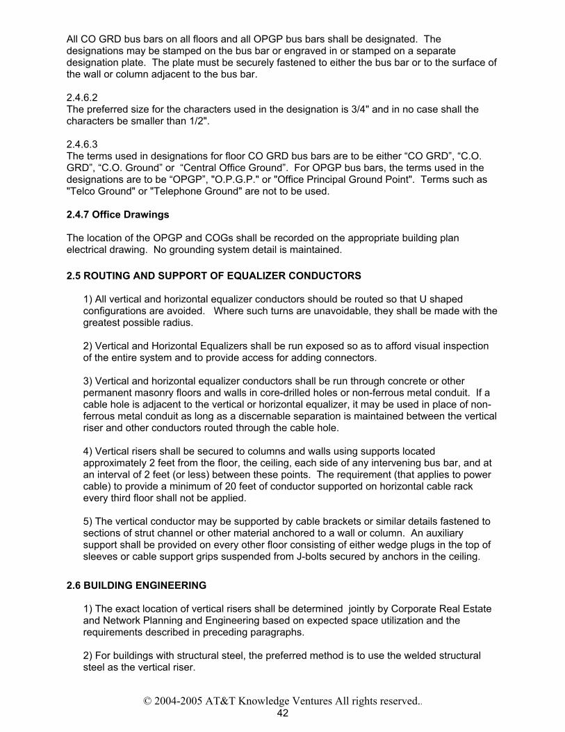
© 2004-2005 AT&T Knowledge Ventures All rights reserved.. 42
All CO GRD bus bars on all floors and all OPGP bus bars shall be designated. The designations may be stamped on the bus bar or engraved in or stamped on a separate designation plate. The plate must be securely fastened to either the bus bar or to the surface of the wall or column adjacent to the bus bar. 2.4.6.2 The preferred size for the characters used in the designation is 3/4" and in no case shall the characters be smaller than 1/2". 2.4.6.3 The terms used in designations for floor CO GRD bus bars are to be either “CO GRD”, “C.O. GRD”, “C.O. Ground” or “Central Office Ground”. For OPGP bus bars, the terms used in the designations are to be “OPGP”, "O.P.G.P." or "Office Principal Ground Point". Terms such as "Telco Ground" or "Telephone Ground" are not to be used. 2.4.7 Office Drawings The location of the OPGP and COGs shall be recorded on the appropriate building plan electrical drawing. No grounding system detail is maintained. 2.5 ROUTING AND SUPPORT OF EQUALIZER CONDUCTORS
1) All vertical and horizontal equalizer conductors should be routed so that U shaped configurations are avoided. Where such turns are unavoidable, they shall be made with the greatest possible radius. 2) Vertical and Horizontal Equalizers shall be run exposed so as to afford visual inspection of the entire system and to provide access for adding connectors. 3) Vertical and horizontal equalizer conductors shall be run through concrete or other permanent masonry floors and walls in core-drilled holes or non-ferrous metal conduit. If a cable hole is adjacent to the vertical or horizontal equalizer, it may be used in place of non-ferrous metal conduit as long as a discernable separation is maintained between the vertical riser and other conductors routed through the cable hole. 4) Vertical risers shall be secured to columns and walls using supports located approximately 2 feet from the floor, the ceiling, each side of any intervening bus bar, and at an interval of 2 feet (or less) between these points. The requirement (that applies to power cable) to provide a minimum of 20 feet of conductor supported on horizontal cable rack every third floor shall not be applied. 5) The vertical conductor may be supported by cable brackets or similar details fastened to sections of strut channel or other material anchored to a wall or column. An auxiliary support shall be provided on every other floor consisting of either wedge plugs in the top of sleeves or cable support grips suspended from J-bolts secured by anchors in the ceiling.
2.6 BUILDING ENGINEERING
1) The exact location of vertical risers shall be determined jointly by Corporate Real Estate and Network Planning and Engineering based on expected space utilization and the requirements described in preceding paragraphs.
2) For buildings with structural steel, the preferred method is to use the welded structural steel as the vertical riser.

© 2004-2005 AT&T Knowledge Ventures All rights reserved.. 43
3) When it is intended that structural steel columns be used as vertical risers, instructions for bonding of the structural steel sections, as described in preceding paragraphs, shall be included in building specifications. 4) When bonding of floor CO GRD bus bars to building steel is required the Building Engineer shall arrange for the addition of the two 3/4" studs or the 750 kcmil conductor to building steel prior to pouring of concrete. 5) The installation of sleeves in floors and requirements associated with building construction should be included in construction specifications. When sleeves are placed at columns, care should be exercised to offset them from the column to miss horizontal beams while not interfering with clear equipment aisle space. 6) Where more than one vertical riser system is required in a building and bonding is required between them, suitably located sleeves through intervening walls that will result in shortest practical run lengths shall be provided.
2.7 AC SYSTEM GROUNDING The AC service distribution system used in a Central Office is usually a single or three-phase 120/208 or 277/480 volt grounded systems. The grounding of these systems includes two sub-systems: the ac service grounding system, covered in 2.7, and the ac equipment grounding system, covered in 2.8. 2.7.1 Grounding Electrode Conductor (GEC) 2.7.1.1 A grounding electrode conductor (GEC) bonds the neutral of an ac power system to an acceptable earth electrode system. The preferred point of connection of the GEC to an earth electrode system is at an OPGP. For the end of the GEC terminated in the main house service panel the preferred location for the connection is the neutral bus bar. If used, any other location for this connection shall meet the applicable requirements in Article 250 of the NEC. 2.7.1.2 Figure 2-3 shows the two preferred methods for connecting the main ac service GEC to an OPGP bus bar and, in turn, to the main cold water pipe or other primary grounding electrode. 2.7.1.3 If a GEC connects to an earth electrode system that does not terminate on the OPGP, a bond equal in size to the GEC is required between the separate earth electrode system and the OPGP. If it provides a shorter path, the conductor from the separate electrode system may terminate at a point on the earth electrode system serving the OPGP (for example to driven ground rods). 2.7.1.4 The neutral conductor of an ac system shall not be connected to a grounded object on the load side of the system's main disconnect device. If the neutral should become open, operating current would flow over the grounding path, potentially raising the voltage on the grounded equipment. 2.7.1.5 The GEC shall be sized per Article 250 of the NEC except that conductors smaller than #2 AWG shall not be used for services, and conductors smaller than #6 AWG shall not be used for the source of a separately derived ac power system in any Company structure. See Table 2-2. 2.7.1.6

© 2004-2005 AT&T Knowledge Ventures All rights reserved.. 44
The GEC may be a bare or insulated, stranded or solid copper conductor. 2.7.1.7 The GEC should be run in the open, or in non-metallic raceway. When required to be in metallic raceway, the raceway must be bonded to the conductor at both ends. If a conductor is used for this bond, it shall be no smaller than the GEC.
Size of Largest Service Entrance Conductor or Equivalent Area for Parallel Conductors
Size of Grounding Electrode Conductor
Copper Aluminum or Copper-Clad Aluminum
Copper
Up to 1/0 AWG Up to 3/0 AWG 6 AWG Over 1/0 thru 3/0 AWG Over 3/0 AWG thru 250 kcmil 4 AWG Over 3/0 AWG thru 350 kcmil Over 250 thru 500 kcmil 2 AWG Over 350 thru 600 kcmil Over 500 thru 900 kcmil 1/0 AWG Over 600 thru 1100 kcmil Over 900 thru 1750 kcmil 2/0 AWG Over 1100 kcmil Over 1750 kcmil 3/0 AWG
Table 2-2
Grounding Electrode Conductor Sizing (Table 250-66 from the NEC)
2.7.2 Main Bonding Jumper 2.7.2.1 A main bonding jumper shall be used to connect the grounded conductor of the system (the neutral) to the equipment grounding conductor and service equipment enclosure. 2.7.2.2 The main bonding jumper shall not be smaller than the sizes given in Table 2-2 above, except that sizes smaller than #2 AWG shall not be used for main house service panels in Company structures. Where the service entrance phase conductors are larger than 1100 kcmil copper or 1750 kcmil aluminum, the bonding jumper shall have an area not less than 12 1/2 percent of the area of the largest phase conductor. 2.7.3 Gounding of Separately Derived AC Systems A separately derived ac power system is a power source that has no direct electrical connection, including a solidly connected grounded circuit conductor, to supply conductors originating in another system. Typical sources are isolation transformers, some inverters and some engine-alternators. 2.7.3.1 A GEC is required between the neutral of the source of a separately derived ac power system and an earth ground reference. 2.7.3.2 In offices equipped with a CO GRD system, the preferred point of connection for a GEC is to the OPGP, a floor CO GRD bus bar, or building steel. In structures without a CO GRD system or building steel, the GEC must be connected to an approved earth electrode. 2.7.3.3

© 2004-2005 AT&T Knowledge Ventures All rights reserved.. 45
Grounding electrode conductors and main bonding jumpers for separately derived ac systems shall be installed per the requirements of 2.7.1 and 2.7.2 above, based on the size of the derived phase conductors. 2.8 AC EQUIPMENT GROUNDING 2.8.1 Feeder and Branch Circuit Equipment Grounding System 2.8.1.1 A separate ACEG conductor shall be provided in all conduits, raceways and other distribution systems containing ac circuit conductors. 2.8.1.2 A separate ACEG conductor shall be provided in all additions, rearrangements or extensions of service, feeder and branch circuit raceways. This includes distribution systems serving both communication equipment and building service equipment. 2.8.1.3 An additional insulated ACEG conductor is required for all circuits feeding isolated ground type outlets. This conductor must remain insulated from contact with any other ground reference between the circuit load(s) and its source (HSP, isolation transformer, dc-ac inverter, etc.). See Section 4.10 4., Special Note on Isolated Ground Type Receptacles, for a discussion of the application of these receptacles. 2.8.1.4 A separate bonding jumper is required between a receptacle and its enclosure with the following exceptions: a) The receptacle is an isolated ground type
b) The enclosure is surface mounted and direct metal-to-metal contact exists between it and the receptacle's mounting yoke c) The receptacle is cover-mounted and the enclosure and cover combination are listed as providing satisfactory ground continuity between the enclosure and the receptacle
2.8.1.5 Except for ACEG conductors serving isolated ground type receptacles, all ACEG conductors shall be bonded to metal enclosures to provide continuity independent of that provided by the raceway. A single bond may be used between multiple ACEG conductors and an enclosure. 2.8.1.6 An ACEG conductor shall be connected to an enclosure by one of the following means: a) A ground bus bar b) A terminal strip c) A grounding bushing d) A grounding clip e) A screw fastener f) The arrangements described in 2.8.1.4 (b) and (c) Grounding clips are normally used only at junction boxes and receptacle enclosures. A screw fastener (machine screw, nut, bolt or stud) must be used for no other purpose than to terminate ACEG conductors. 2.8.1.7 ACEG conductors shall never be connected to an ac neutral at any point other than where the source of the system receives its ground reference.

© 2004-2005 AT&T Knowledge Ventures All rights reserved.. 46
2.8.1.8 The inclusion of an ACEG conductor in a raceway shall not be counted in determining the ampacity of conductors in accordance with Note 8 associated with Tables 310-12 and 310-14 of Article 310 of the National Electrical Code. 2.8.1.9 The ACEG conductor shall be included in calculations of allowable percentage of conduit fill defined in Chapter 9, Table 1 of the National Electric Code. 2.8.1.10 As a minimum, all ACEG conductors and bonds between them and metallic enclosures shall be sized per Table 2-3 below, which is from Article 250 of the NEC. When phase conductors are increased in size to compensate for voltage drop, the size of associated ACEG conductor(s) shall be increased proportionately. 2.8.1.11 Where conductors are run in parallel in multiple raceways, ACEG conductors shall be run in parallel. Each parallel ACEG conductor shall be sized on the basis of the ampere rating of the over current device protecting the conductors in the raceway in accordance with Table 2-3. 2.8.1.12 Insulated ACEG conductors shall be colored green or green with one or more yellow stripes. Conductors larger than #6 AWG may be identified by marking the exposed insulation with green tape or paint at each end and at every point where the conductor is accessible. 2.8.1.13 When multiple ac circuits share a common raceway, only one ACEG conductor is required for the raceway. Its size shall be based on the largest over current device serving circuits in the raceway. 2.8.1.14 The ACEG conductor in a circuit serving equipment in a frame, cabinet or other metallic enclosure that also contains dc-powered equipment may not be used in place of the required bond between the enclosure and the CO GRD system. 2.8.1.15 While ACEG conductors are considered part of (and bonded to) the CO GRD system, no other CO GRD conductor may serve in place of an ACEG conductor. Bonds between the CO GRD system and ac power distribution system components shall not be used in place of any ACEG conductor.
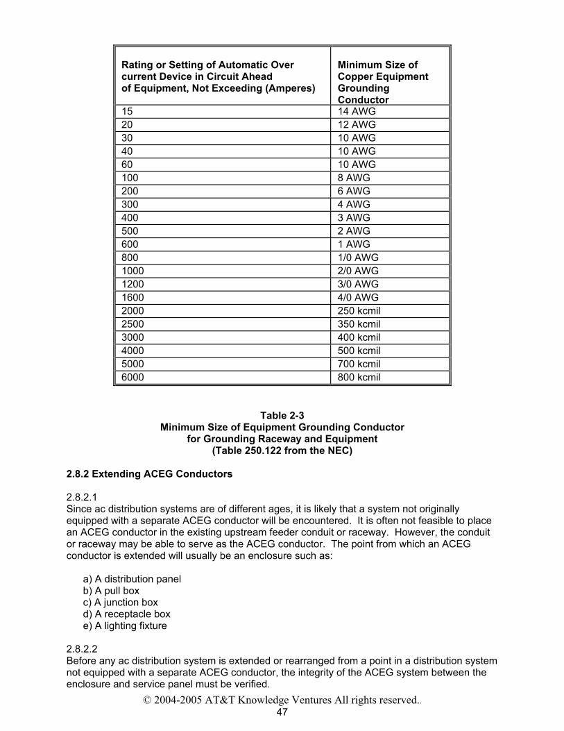
© 2004-2005 AT&T Knowledge Ventures All rights reserved.. 47
Rating or Setting of Automatic Over current Device in Circuit Ahead of Equipment, Not Exceeding (Amperes)
Minimum Size of Copper Equipment Grounding Conductor
15 14 AWG 20 12 AWG 30 10 AWG 40 10 AWG 60 10 AWG 100 8 AWG 200 6 AWG 300 4 AWG 400 3 AWG 500 2 AWG 600 1 AWG 800 1/0 AWG 1000 2/0 AWG 1200 3/0 AWG 1600 4/0 AWG 2000 250 kcmil 2500 350 kcmil 3000 400 kcmil 4000 500 kcmil 5000 700 kcmil 6000 800 kcmil
Table 2-3 Minimum Size of Equipment Grounding Conductor
for Grounding Raceway and Equipment (Table 250.122 from the NEC)
2.8.2 Extending ACEG Conductors 2.8.2.1 Since ac distribution systems are of different ages, it is likely that a system not originally equipped with a separate ACEG conductor will be encountered. It is often not feasible to place an ACEG conductor in the existing upstream feeder conduit or raceway. However, the conduit or raceway may be able to serve as the ACEG conductor. The point from which an ACEG conductor is extended will usually be an enclosure such as: a) A distribution panel b) A pull box c) A junction box d) A receptacle box e) A lighting fixture 2.8.2.2 Before any ac distribution system is extended or rearranged from a point in a distribution system not equipped with a separate ACEG conductor, the integrity of the ACEG system between the enclosure and service panel must be verified.

© 2004-2005 AT&T Knowledge Ventures All rights reserved.. 48
This is done by determining whether an acceptable type of conduit or raceway has been used and by verifying the tightness of the fitting(s) used to fasten the conduit or raceway to the enclosure 2.8.2.3 For existing distribution systems not equipped with a separate ACEG conductor, the only types of conduit or raceway allowed to serve as an ACEG conductor are: a) Electrical metallic tubing (EMT) b) Intermediate metal conduit (IMC) c) Rigid metal conduit d) Metal raceways listed for grounding If none of the above is present in the upstream feed to the enclosure, no circuit shall be extended from the enclosure until corrective action has been performed. 2.8.2.4 The ACEG conductors being added shall be terminated to the enclosure by one of the means in Section 2.8.1.6 above. 2.8.2.5 If more than two ACEG conductors are being added (typically at a distribution panel), it is preferable to add a ground bus to the panel. This bus may be bonded to the panel using its mounting screws provided the paint is removed from the mounting surface of the panel and an antioxidant compound is applied to the bare metal. 2.8.3 AC Power Distribution Cabinets 2.8.3.1 Every ac power distribution cabinet requires an ACEG conductor in the conduit or raceway containing the feeder conductors serving the cabinet. 2.8.3.2 ACEG conductors shall terminate on the interior of the cabinet enclosure on a bus bar bonded to the cabinet enclosure or one of the methods in 2.8..1.6 (b) thru (e). 2.8.3.3 Except for cabinets containing the service disconnecting means, the neutral bar must be insulated from the enclosure and the equipment ground bar. 2.8.3.4 The ACEG conductor provided with feeder conductors provides an acceptable extension of the CO GRD system to an ac distribution cabinet and ac powered equipment only when the ac system's source receives its ground reference on the same or adjacent floor to that on which the cabinet is located. Otherwise, the cabinet shall be bonded to the floor CO GRD system using a minimum #6 AWG conductor. This helps to minimize any difference in ground reference voltage between DC components that receive ground reference from the COG on each floor and AC components that have a ground reference from the OPGP. 2.8.4 AC Bus Duct System 2.8.4.1 AC bus duct components shall maintain equipment ground continuity throughout the bus duct system. Feeder tap boxes and plug-in units are considered to be adequately bonded through mechanical interconnection to bus duct sections. 2.8.4.2

© 2004-2005 AT&T Knowledge Ventures All rights reserved.. 49
The ACEG conductor(s) associated with bus duct feeder and distribution circuits shall be furnished in accordance with requirements above. 2.8.5 Engine-Alternator Sets 2.8.5.1 Engine-alternator and inverter derived ac supplies provided in case of commercial power failure are normally controlled through automatic or manual switching so that the phase conductors of the standby supply are never joined to the commercial supply. The neutral conductor of the standby supply is normally directly connected to the neutral of the commercial secondary service. The grounding electrode conductor (GEC) of the secondary service system serves as a ground reference for both the standby and commercial systems and such systems do not require a separate GEC. However, in some cases the use of ground fault protection will mandate that the neutral be switched.
Exception: When an engine-alternator set is located in a separate building that has its own earth electrode system, the standby system's neutral shall also be connected to that earth electrode system.
If the transfer switch does switch the neutral, then the engine-alternator or inverter is considered the source of a separately derived system and must be equipped with a GEC and a main bonding jumper. 2.8.5.2 An ACEG conductor is always required in the conduit(s) or raceway(s) containing phase leads from the alternator, and shall be furnished in accordance with the requirements above. 2.8.5.3 The ACEG conductor(s) shall terminate within the engine-alternator cabinet provided for the phase leads. Termination may be made on a bus bar or ground stud bonded to the cabinet or directly to the cabinet interior. The cabinet must be electrically connected to the engine-alternator frame by mounting bolts or by a bonding strap or equivalent means to provide continuity between the entire set and the ACEG conductors. 2.8.5.4 The neutral of the alternator shall not be bonded to the ACEG conductor or engine-alternator frame when it is located in the same building as the main ac service panel. The neutral shall be bonded to the ACEG conductor only when the set is located in a separate building equipped with its own earth electrode, or if the neutral is switched. 2.8.6 Grounding of AC Tap Boxes 2.8.6.1 Every ac tap box shall be equipped with an ACEG bus bar. This bus bar shall be bonded to the metalwork of the tap box by its mounting hardware or by a separate bonding conductor. 2.8.6.2 A separate ACEG conductor shall be furnished in the raceway serving the tap box. The ACEG conductor shall be installed per the requirements in Section 2.8 1 except that the size of the ACEG conductor shall be based on the rating or setting of the over current protective device installed in the circuit between the tap box and the system it serves. 2.8.6.3 If the transfer switch for a site's engine-alternator switches the neutral conductor, the neutral bus bar of the tap box shall be equipped with a GEC and a main bonding jumper per the requirements in 2.7 A. and 2.7 B. above.

© 2004-2005 AT&T Knowledge Ventures All rights reserved.. 50
2.8.7 Cord Connected AC Operated Equipment 2.8.7.1 Parallel polarized U ground slot receptacles are standard for frame base appliance outlet and other miscellaneous ac branch circuit applications serving cord connected equipment. Such equipment, whether portable or permanently mounted, shall be equipped with a three-conductor cord and a three-conductor grounding attachment plug. Two conductors of the cord shall serve as circuit members. The third conductor shall serve as a grounding member, connected at the plug to the U blade, and to the equipment structural metal, so that ground continuity is established from the receptacle to the equipment structure. 2.8.7.2 When branch circuit conductors are not run in electrically continuous metallic raceway an ACEG conductor must be provided from the panel board to the receptacle. The ACEG conductor shall be bonded to the metal outlet box or other metallic enclosure mounting the receptacle as well as the EG (green) terminal screw of the receptacle. 2.8.7.3 If ground continuity is not provided to the U ground slot via the receptacle mounting members, a bonding jumper is required. 2.8.7.4 Certain equipment still in use may be equipped with 2-pole ungrounded plugs and 2-conductor cords. Unless protected by an approved system of double insulation, such units are potentially hazardous. Such cord and plugs shall be replaced with 3-conductor cords and 2-pole, 3-conductor grounded plugs. 2.8.7.5 Where units suitably arranged for grounding are used in offices with 2-pole ungrounded receptacles, the plug shall be equipped with a ground conductor type adaptor to ensure that grounding facility is available. 2.8.7.6 Frame mounted ac operated equipment now in service served with 2-conductor cord and ungrounded plugs need not be modified for a grounded system where it can be ascertained that these permanently mounted units have continuity through the frame to the raceway enclosing the branch circuit conductors 2.8.7.7 Generally, all new ac operated portable or permanently mounted equipment units utilizing cord and plug for ac supply shall be supplied with 3-conductor cords and 2-pole, 3-conductor grounded plugs that function to ground the unit structure. The only exceptions shall be for tools such as soldering irons that must be employed on or near circuit connection points that may have dc potential, where contact with the tool would constitute a short to ground, or for other specialized requirements of similar nature. 2.8.8 Job Drawings, Architectural 2.8.8.1 AC distribution system circuit requirements for specific job installations shall be recorded on drawings prepared by the building architect and/or the communication systems equipment engineer.

© 2004-2005 AT&T Knowledge Ventures All rights reserved.. 51
2.8.8.2 An ACEG system shall be provided, as specified in this section, in the portion of the ac distribution system controlled by architectural drawings. The ACEG conductors shall be shown on the plans in a similar manner to that of phase and neutral conductors. Methods of termination and other information necessary for proper installation shall be provided. 2.8.8.3 For the purpose of establishing a standard identification of ACEG conductors shown on circuit schematic, wiring diagram and job circuit drawing, it is recommended that lead identification at points where an ACEG lead is referenced to other circuit figures or other drawings shall use letter designation, as follows: ACEG 2.8.9 Rooftop Facilities The rooftops of central office buildings may support a number of diverse components that require some degree of bonding and grounding coordination. Rooftops may include lightning protections systems, communication antennas, standby generators, air-handling units, vents, fences and metal “penthouse” enclosures. Items to consider:
1) Lightning protection systems and communications antennas will have independent rooftop ring ground conductors, down conductors and grounding electrodes that will be bonded to the other building-related grounding electrodes at ground level. 2) Lightning protection systems may use building steel for down conductors if the steel is electrically continuous. 3) Air terminals of lightning protection systems must be connected to building steel where the building steel is electrically continuous. 4) Conductive objects that are not part of the lightning or antenna protection system and that are within 7’ of a lightning or antenna conductive object shall be bonded to the lighting or antenna ground ring with a minimum #6 AWG conductor (whether or not also bonded to the CBN). Where building features do not provide adequate physical protection to the wire, cover the wire with "U" shaped metallic channel or other non-conductive cover.
5) Generator sets that are mounted on the rooftop shall be bonded to building steel (minimum #6 AWG) where the building steel is electrically continuous, otherwise bond to the CBN. 6) If equipment is added to a rooftop (e.g. generators, penthouses, remote radiators, etc), these items may become the primary attractant to lightning strikes. An evaluation of conditions (height of additional equipment, height of building and surrounding buildings, incidence of lightning, etc.) should be conducted with Corporate Real Estate to determine if a lightning protection system is warranted.
2.9 COORDINATION WITH CORPORATE REAL ESTATE The AT&T Corporate Real Estate (CRE) group has responsibility for the cost effective design and construction of central office facilities that meet network requirements. Part of the power and grounding infrastructure that is required for the safe and reliable operation of network equipment is provided by CRE and part is provided by NP&E. Table 2-4 provides a generalized listing of these responsibilities that will likely vary somewhat between the various regions. Which group has primary or secondary responsibility may not be critically important. What is important is that:

© 2004-2005 AT&T Knowledge Ventures All rights reserved.. 52
1) NP&E staff provide timely input to CRE regarding growth or changing infrastructure requirements.
2) CRE allow NP&E opportunity to review proposed designs before the start of construction.
3) Everyone recognize the importance of coordination. Notes for Table 2-4: 1) CRE = Corporate Real Estate 2) P = Primary responsibility and S = Secondary Responsibility 3) Primary responsibility includes planning, specifying, budgeting, scheduling and
implementation after consultation with those who may have secondary responsibility. 4) Primary responsibility is within the OSP organization. 5) When NP&E has secondary responsibility, they are responsible for timely delivery of any network-related specifications for use by CRE.

© 2004-2005 AT&T Knowledge Ventures All rights reserved.. 53
Design Install Maintain Item Description
CRE NPE CRE NPE CRE NPE Grounding Electrode System
Building ring, UFER, underground water pipe, building steel, OPGP and all bonds to OPGP
P S P P
Building Steel Qualify building steel as suitable for grounding electrode / vertical riser.
P
Building Steel Selection of building steel as vertical riser
S P
Building Steel All bonding attachments to building steel
P S P P
AC Service Bonds Bonds from ACEG and Neutral bus to grounding electrode system
P S P P
Cable Entrance Facility
Bonds from CEF to OPGP, ACEG
P S P
Cable Entrance Facility
Bonds from Cable sheath to CEF bus
S4 S4 S4 S4 S4 S4
AC Distribution To facility infrastructure P P P
AC Distribution To network line-ups P P P
Ground Reference Distribution
Vertical Riser, COG S P P P
Common Bonding Network
All connections from COG to network elements and foreign objects
P P P
Isolated Bonding Network
All connections to MGB, isolation from CBN
P P P
Ground distribution to DC Power
Ground connections to equipment frame and battery return of DC power plant
P P P
Evaluate the need for building lightning protection
Consideration for frequency of lightning, cone of protection, historical data
P S
Building Lightning Protection
Design and Install P P P
Separately Derived Power
Bonding of Generators S P P P
Separately Derived Power
Bonding of Inverters P P P
Separately Derived Power
Bonding of UPS S P P P
Grounding Electrode System –CEV
Ground rods, ring & connection to OPGP
S4 S4 S4 S4 S4 S4
Grounding Electrode - Radio Site
Exterior ring, interior ring, tower ring
P S P P
Table 2-4
NP&E / CRE Responsibilities

© 2004-2005 AT&T Knowledge Ventures All rights reserved.. 54
SECTION 3 Power Plants and Equipment, Transport
and Miscellaneous Equipment 3.1 SCOPE This section covers requirements and information about connections between a central office ground system and:
• Power equipment • Transport equipment • Miscellaneous equipment frames and units • Cable entrance facilities • Protector and distributing frames • Power systems serving the above and other types of equipment
3.2 GENERAL This section provides requirements for equipment that is normally installed in a common bonding network environment. It includes requirements for power plant equipment and power distribution systems that serve both common bonding network and isolated bonding network equipment. Where requirements are specified in circuit drawings or specifications of equipment approved for use, they shall have precedence over the general requirements of this section. Where grounding requirements are not furnished in system specifications or where they have not been updated to the requirements outlined in this section, a grounding system of equal requirements covered in this section shall be provided. Equipment specifications devised prior to the introduction of the CO GRD system may not include grounding requirements that make use of horizontal and vertical equalizers. 3.2.1 An Overview of Power and Grounding Systems 3.2.1.1 Network equipment and the power and grounding systems that serve them are often a mixture of designs from different eras. Modern equipment may be served by older power and grounding systems and vice versa. 3.2.1.2 It was once standard practice to connect battery return conductors (also called ground or discharge ground) to bus bars that were in electrical contact with equipment framework. This provided a means to ground the equipment frames by extending the CO GRD system only to critical points in the battery return network. These points were primarily horizontal equalizer connections to the return bus bars of BDFBs, equalizing centers and similar points in distribution systems. The conductors between these points and equipment frames functioned as both a battery return (grounded) and a framework ground (grounding) conductor. 3.2.1.3 This arrangement also causes dc current (battery return current) flow throughout the huge parallel network formed by the many metallic paths that are part of bonding and grounding networks. While this separation of battery return and framework ground has been a design requirement for some time, equipment (especially power distribution equipment) designed prior to this approach is still in use. Today, there is much less dc current flow on grounding systems in central offices.

© 2004-2005 AT&T Knowledge Ventures All rights reserved.. 55
In the future, there may be much less or there may be much more current flow. This will depend on the design of the equipment as well as the power distribution and grounding systems. 3.2.1.4 Another common practice was to place general purpose power plants of different voltages reasonably close together. One plant was chosen as the predominant plant. This was most often the 48-volt plant, since it was generally the one with the greatest ampere capacity. 3.2.1.5 Some BDFBs served by different plants have fuse panels dedicated to different voltages, but the BDFB is equipped with a single, common battery return bus bar. A battery return conductor calculated to serve as a combined battery return path for all voltages present in the BDFB is provided between the BDFB and the predominant power plant. One or more conductors calculated for voltage drop are provided between the battery return bus bars of the predominant plant and other plants. The bonds serve to complete the battery return path (to the batteries), and to provide ground reference to the other power plant(s). 3.2.1.6 Some of the arrangements described above are no longer acceptable. While a common battery return bus bar may still be used in a BDFB, the battery conductors from all power plants serving the BDFB and the distribution circuits from the BDFB should be equipped with paired battery return conductors. Also, the bond between two power plants' battery return bus bars should be augmented by a separate conductor to a CO GRD or OPGP bus bar from the battery return bus bar of each plant. 3.2.1.7 These issues are presented as a reminder that they often must be considered during power and ground system additions, removals and rearrangements. 3.3 DC POWER SYSTEMS DC power plants have been categorized as general purpose plants, special voltage plants, converter plants and in the past, dedicated plants. General Purpose Plants are used to provide 24-volt, 48-volt, and 130-volt power to switching, transport, radio and miscellaneous equipment. Individual plants are provided for each voltage and polarity required. Special Voltage plants provide a voltage (i.e., 140 volts) that is suitable for feeding converters, but not normally suitable for direct connection to communication equipment. Converter plants change dc power from one voltage to another, most often from 48 volts to 130 volts. Dedicated plants were used for radio systems and for electronic switches that had specific restrictions against sharing a power plant with other types of equipment. 3.3.1 Battery and Converter Plants, DC-DC Converters 3.3.1.1 The return side of every dc power source shall be referenced to the site’s grounding system with a dc system grounding conductor. This applies to all battery plants, converter plants and all converters mounted in equipment frames, cabinets or other enclosures, whether or not the dc source serves loads located in the same enclosure. Where two or more plants use a combined battery return arrangement, each plant should have a separate bond from its battery return to the CO GRD system.

© 2004-2005 AT&T Knowledge Ventures All rights reserved.. 56
3.3.1.2 For battery type plants, the default size for the system grounding conductor shall be 750 kcmil. Using Table 3-1, a smaller conductor may be allowed. Its minimum size shall be based on the maximum plant capacity specified by the manufacturer. If a battery plant has been assembled from discrete components (batteries, rectifiers, fuse panels, etc.) and has no maximum capacity value, the system grounding conductor shall be based on the combined output rating of all installed rectifiers.
Power Plant Capacity (Amperes)
Minimum Size of System Grounding Conductor
up to 100
6 AWG
101 – 500
2 AWG
501 – 1199
4/0 AWG
1200 +
750 kcmil
Table 3-1
Battery Plant System Grounding Conductor Sizing 3.3.1.3 When approved for use, power plants and equipment with imbedded power arrangements may use conductor sizes other than those shown in Table 3-1. For such installations, the conductor should be the minimum size specified by the manufacturer of the equipment. 3.3.1.4 The dc system grounding conductor may be placed directly between a power plant's battery return bus bar and a CO GRD or OPGP bus bar or a point on a 750 kcmil horizontal equalizer. It may also be connected to the CO GRD system by a connection to a Main Ground Bus (MGB) in a ground window. The conductor between a power plant's battery return bus bar and a CO GRD or OPGP bus bar is considered a part of the horizontal equalizer system. Conductors normally permitted to connect to a horizontal equalizer may terminate on this conductor. 3.3.1.5 The minimum size of the system grounding conductor for dc-dc converters shall be that shown in Table 3-2, based on the output fault current rating of the converter. The fault current rating shall be the rating of the output over current protective device or the current limit inception value if no protective device is furnished. The system grounding conductor provides the ground from the equipment to the equipment frame or enclosure and may be smaller than a #6AWG. The minimum size for an equipment frame or enclosure conductor to the CO GRD system is a #6 AWG.

© 2004-2005 AT&T Knowledge Ventures All rights reserved.. 57
Over current Device Rating or Current Limit Inception Not Exceeding (Amperes)
Minimum Size of System Grounding Conductor (AWG)
15
14
20
12
30
10
40
10
60
10
100
8
200
6
300
4
400
3*
500
2
600
1*
Table 3-2
System Grounding Conductor Sizing for DC-DC Converters (From Table 250-122 of the NEC)
*NOTE: Historically, #3 AWG and #1 AWG have not been readily available from suppliers and AT&T has standardized on the next larger size (#2 and #1/0 respectively). 3.3.1.6 For converter plants consisting of two or more converters with outputs connected in parallel, the size of the system grounding conductor shall be based on the combined fault current available from a fully equipped converter plant as specified by the manufacturer. When the output of multiple converters embedded in equipment share a common distribution path via back plane layers, conductors or bus bars, the system grounding conductor shall be sized on the combined maximum available fault current. 3.3.1.7 Some equipment designs use dc-dc converters whose output is referenced to ground via the converter's input battery return conductor. In this case, the converter's input battery return conductor shall be no smaller than that required per 3.3.1.5, 3.3.1.6 and Table 3-2. 3.3.2 140-Volt Power Plant and Distribution System 3.3.2.1 The 140-volt plant and distribution system is a special voltage plant that primarily serves converters and converter plants for #4ESS.

© 2004-2005 AT&T Knowledge Ventures All rights reserved.. 58
The converters supply voltages required by the #4ESS equipment. The ground systems of the input and output sides of the converters are isolated from each other. 3.3.2.2 Single point grounding of the isolated bonding network portion of the 140-volt distribution system is via a minimum #1/0 AWG conductor, and is connected to the 140-volt system from a CO GRD bus on the distribution system's midpoint floor level. 3.3.2.3 The midpoint floor level is determined on the basis of building floors encompassed in a single 140-volt distribution system. The system may only serve equipment on five floors above and below the midpoint floor on which a bond to the CO GRD bus bar is made. 3.3.3 POWER SYSTEM EQUIPMENT GROUNDING 3.3.3.1 All frames, cabinets and other components of a power plant must be equipped with a minimum #6 AWG bond to the CO GRD system. This includes frames in a power board lineup, rectifier bays, metal battery stands, etc. The power plant lineup conductor should be sized to accommodate the maximum expected primary distribution. For 600A distribution, the power plant lineup conductor shall be a #1/0 AWG minimum and shall be connected to the nearest:
a) DC System Grounding Conductor (when MGB is part of the power plant battery return) b) MGB (when MGB is part of the power plant battery return) c) Horizontal Equalizer of equal or greater size d) CO GRD or OPGP bus bar
DCEG conductors for power plant frames, cabinets and other equipment shall be branched from a power plant lineup conductor. A typical power area grounding arrangement is shown in Figure 3-1.
3.3.3.2 The DC system Grounding Conductor extends from the battery return bus bar to the CO GRD (or OPGP) for all power plants except shared power plants with a remote MGB. This is a 750 kcmil conductor. 3.3.3.3 For any equipment frame, cabinet or other enclosure containing rectifiers, the minimum size for a DCEG conductor shall be #6 AWG. Table 3-3 shall be used to determine the size of the framework ground conductor based on the size of the output rating of the largest rectifier in the framework. The current limiting or over-current protection feature of rectifiers may not activate until 110% of the rated current output is reached. For example, a 400-ampere rectifier may not shut down until reaching 440 amperes. The conductor size in Table 3-3 is based on Table 250-122 from the NEC.

© 2004-2005 AT&T Knowledge Ventures All rights reserved.. 59
Rectifier/Inverter Output Rating (Amperes)
Rectifier/Inverter Current Limit (Amperes)
DCEG Conductor Size
up to 100
up to 110
6 AWG
200
220
4 AWG
400
440
2 AWG
Table 3-3
Rectifier/Inverter DCEG Conductor Sizing (From Table 250-122 of the NEC)
3.3.3.4 The DCEG conductor for any dc-to-ac inverter shall be a minimum #6 AWG. Table 3-3 shall be used to determine the minimum size for the DCEG conductor based on the rating or setting of the dc input circuit's over current protective device. This requirement applies to all stand-alone inverters and to all bay-mounted inverters. This DCEG conductor is required in addition to the ACEG conductor for the ac input and/or output circuits. If the inverter is the source of a separately derived system, this conductor is also required in addition to the Grounding Electrode Conductor. 3.3.4 Engine Alternator Equipment 3.3.4.1 For engine rooms located within a structure, the grounding system shall be the same used for equipment in a power room: minimum #6 AWG bonding conductors shall be branched from a minimum #2 AWG main conductor extended from the CO GRD system and routed through the engine room. The actual conductor size is based on the requirements of Table 2-3. Certain objects must always be bonded to this extension of the CO GRD system. These include: a) The frame of any engine-alternator set b) A metallic engine start battery stand c) A metallic day tank (by a bond to its support/hold down structure) d) If not electrically or mechanically joined to an object that is bonded, a point on the
overhead ironwork system or metallic support structure A separate bonding conductor is not required for cabinets, enclosures or other units in an engine room that are equipped with an ACEG or other bonding conductor extended from an object already bonded to the engine room grounding system. For items not mentioned above, a separate bonding conductor is only required for objects that are likely to become energized, such as a metal radiator shroud equipped with a load bank. A bond is not required for objects not likely to become energized such as metal door and window frames, vent ducts, louvers, shrouds, etc. 3.3.4.2 A small equipment unit that is exclusively ac-powered (tank monitor, etc.) is considered effectively bonded to the CO GRD system via its ACEG conductor.

© 2004-2005 AT&T Knowledge Ventures All rights reserved.. 60
3.3.4.3 An engine alternator located in a separate, stand-alone enclosure outside a central office building or other structure may use the ACEG conductor(s) furnished in feeder conduits between the enclosure and the main structure as the bond to the CO GRD system. If an engine alternator in a stand-alone enclosure is configured as the source of a separately derived system, a grounding electrode conductor must be used to bond the neutral of the alternator to an earth electrode. Depending on site conditions, this may be the same earth electrode system used for the CO or it may be a separate earth electrode system. Requirements for a grounding electrode conductor and main bonding jumper are provided in Section 2.7 AC SYSTEM GROUNDING. 3.3.4.4 Metallic objects that are part of a remotely located engine alternator enclosure must be bonded together. The preferred method is to use separate bonding conductors, but units may also be considered bonded together if joined by welds, rivets, or other adequate mechanical means. 3.3.4.5 Fuel tanks, radiators and other conductive components of the engine-alternator set that are not effectively grounded to the engine-alternator through mechanical means shall be bonded with a #6 AWG conductor to the engine-alternator skid, cabinet or to a grounding electrode system.

© 2004-2005 AT&T Knowledge Ventures All rights reserved.. 61
Battery Stand A
Control and600 A
Distribution
400 ARectifiers
Battery Stand B
200 ARectifiers
A
B
E
A - 750 kcmilB - #2 AWGC - #4 AWGD - #6 AWG
ED
D
E
E
B
B
To CO GRD orRemote MGB
Ringing Plant
C
C
D
DC-AC Inverter100 A DC Inuput Fuse
Battery ReturnBusbar
130V Converter Plant
BTo Engine Alternator Room
B
CC
C C
Insulated
Output Return Bus Bar
CMaximum Output: 200 A
E - #1/0 AWG
E
To CO GRD or DC SystemGrounding Conductor
(see section 3.3.3)DC SystemGroundingConductor
Figure 3-1
Typical Power Area Grounding Arrangement 3.4 POWER DISTRIBUTION SYSTEMS A variety of equipment and conductor configurations have been used to ground and to distribute dc power to communication systems. While some of these equipment systems may no longer exist, all or part of their original grounding and/or power distribution systems may still be in use. All are described below, but only (a) through (d) should be part of new or growth jobs:

© 2004-2005 AT&T Knowledge Ventures All rights reserved.. 62
1) Distribution by means of paired battery and return conductors from power plant distribution bays to power distribution frames (PD, PDC, PCFD, etc.) within electronic switching equipment. From the distribution frames, paired conductors extend to equipment bays. Refer to Section 4 of this Practice for a discussion of typical distribution systems and grounding arrangements.
2) Distribution by means of paired battery and battery return conductors from a 140-volt dc power plant (415 type) to area bus centers (ABC) on each equipment floor. Circuits using paired conductors are extended to bulk converter plants and to converters on equipment bays. The 140-volt distribution system is part of an isolated bonding network and contact with the common bonding network is restricted to a single point. 3) Distribution by means of paired battery and return conductors from power plants to battery distributing fuse boards (BDFB), by paired conductors to individual equipment bays or lineups, and to centrally located fuse boards. 4) Direct distribution by means of paired battery and battery return from power plants to fuse panels in individual equipment bays. 5) Distribution by means of paired battery and returns from power plants to centrally located fuse boards. Distribution from fuse boards to load units may be by means of paired battery and returns or by means of individual battery conductors and a common battery return conductor between frame mounted bus bars and the fuse board battery return bus bar. 6) Distribution by means of paired battery and battery return conductors from power plants to equalizing centers, then by equalizer conductors along the main aisle of an equipment block. Battery and return conductors are tapped and extended to each frame line in the equipment block. The battery conductor is routed through a 100-ampere fuse at the head of the lineup, extended along the lineup and tapped to feeders connected to fuse panels in equipment bays. 7) Distribution by means of paired battery and return conductors from power plants to battery distribution circuit breaker boards (BDCBB). Branch circuits were extended from BDCBBs via paired conductors to radio and other equipment bays. This system was standard for TD-3 and TH-3 Microwave Radio stations.
3.4.1 Battery Distributing Fuse Board (BDFB) 3.4.1.1 BDFBs are used to distribute one or more dc voltages to network equipment. The battery return bus bars on early BDFBs were in electrical contact with the framework of the BDFB. All new BDFBs should have the bus bar insulated from the framework. 3.4.1.2 If a power plant serves two or more BDFBs with non-insulated battery return busses, these battery return busses shall be connected with a 750 kcmil conductor to the CO GRD system bus bar or to another horizontal equalizer. The non-insulated contact with the CO metal work can cause noise currents to flow between the BDFBs when the respective return bus bars are at different potentials (e.g., due to different load currents). This connection provides a low resistance path to ground and will help to mitigate any noise currents that may flow between the two BDFBs. The 750 kcmil conductor is required in all cases where the BDFBs are on the same floor and may be required when the BDFBs are on different floors. In the later case, the presence of unwanted noise indicates the conductor should be considered.

© 2004-2005 AT&T Knowledge Ventures All rights reserved.. 63
3.4.1.3 The DCEG conductor for BDFBs shall be a minimum #1/0 AWG conductor, and shall be connected directly to a CO GRD bus bar or tapped to a horizontal equalizer of equal or greater size. 3.4.1.4 When a #1/0 AWG conductor is added between the BDFB framework and a CO GRD bus bar, it may serve other BDFBs as well as other equipment lineups. If more than one BDFB is in a lineup, a single #1/0 AWG conductor may serve every BDFB in the lineup. Where applicable, this conductor may also serve in place of the #6 AWG lineup grounding conductor. 3.4.2 Fuse Boards (F BD) 3.4.2.1 Fuse boards were used in older network equipment systems as an intermediate distribution point. They served units mounted in relay rack bays in the vicinity of the fuse board and were fed either from remote BDFBs or directly from a power plant. While rare, some are still in use, and the grounding requirements for them have been retained in this section. 3.4.2.2 With the exception of F BDs furnished in toll systems, F BDs equipped with battery return buses in electrical contact with the frame need not be bonded to the CO GRD system when the predominant power supply is furnished from a BDFB or a power plant on the same floor, and the length of the battery return conductor from the BDFB to the F BD is 50 feet or less. 3.4.2.3 When the F BD receives its predominant supply from a power plant on another floor, or the battery return conductor from the BDFB to the F BD is longer than 50 feet, a bond between the F BD battery return bus and a point on the CO GRD system is required. It shall be a #4/0 AWG conductor when the bond serves only one fuse bay. When more than one fuse bay in a floor segment requires bonding with a conductor, a single 350 kcmil bond, run in the most direct manner between F BDs, shall be used to bond them together and to the nearest acceptable junction point to CO GRD. 3.4.2.4 Miscellaneous fuse boards that are not equipped with a frame ground bus bar or occupy less than a full bay or other frames that contain a fuse panel, and power ringing and tone distribution (PRTD) frames are considered to be adequately grounded through conductive paths inherent in the assembly of the system. These types of power distributing equipment do not require bonding as described previously for the purpose of providing current paths between battery return conductors.

© 2004-2005 AT&T Knowledge Ventures All rights reserved.. 64
CO GRD
4th Floor
#1/0 AWG
750 kcmil
BDFB
750 kcmil
#1/0 AWG
CO GRD
2nd Floor
Vertical Equalizer
to OPGP
Calculated BatteryReturn Conductors
To Isolated BondingNetwork Equipment
Insulated BatteryReturn Bus Bar
Insulated BatteryReturn Bus Bar
Power Plant
750 kcmil
#1/0 AWG
1st Floor
BDFB
CO GRD
3rd Floor
Insulated BatteryReturn Bus Bar
750 kcmil
MGB
CO GRD
BDFBGround Window
Insulated BatteryReturn Bus Bar
750 kcmil
#1/0 AWG
Figure 3-2 Power Plant Serving Both Common & Isolated Bonding Network Equipment
3.5 TRANSPORT, INFORMATION TECHNOLOGY AND MISCELLANEOUS EQUIPMENT
Power Plant

© 2004-2005 AT&T Knowledge Ventures All rights reserved.. 65
3.5.1 Equipment Enclosure and Unit Requirements 3.5.1.1 Nearly all transport, information technology and equipment other than switching systems, whether in a company-owned structure or on customer premises, is located in an area that is part of the common bonding network. These areas contain an assortment of equipment, often in a variety of frames, cabinets, and other enclosures. Any given equipment area may contain several generations of technology from a wide assortment of vendors. While some radio equipment may be classified as transport equipment, it is covered in Section 6 of this Practice. 3.5.1.2 All bonds to the CO GRD system mentioned in paragraphs 3.5.1.3 - 3.5.5.4 shall be made to the nearest point on the horizontal equalizer system that is of equal or larger size, or if no horizontal equalizer exists, to the nearest CO GRD or OPGP bus bar. 3.5.1.3 There are four requirements that apply to transport, information technology and any other equipment:
a) The equipment enclosure must be equipped with a bond to the CO GRD system that is capable of safely conducting any fault current likely to be present at the enclosure. b) Every bond to the CO GRD system, both from and within equipment frames, cabinets or other enclosures, must consist of electrical conducting paths that are intentionally designed and provided for the purpose. Unit or enclosure metalwork may be used in place of a bonding conductor to the CO GRD system if the chassis of an equipment unit, shelf, etc., has been made electrically continuous with the frame, cabinet or other enclosure metalwork (see 3.5.1.5 and 3.5.1.6). c) The bond from the equipment to the CO GRD system shall not be used in place of a dedicated return conductor to conduct normal load current. It is important to be aware, however, that even though frame grounding conductors are not designed to carry load current, industry standards allow some current flow between the battery return conductor and the equipment frame for equipment located in the Common Bonding Network (CBN). This can result in less than 100% of the load current returning over the battery return conductor. d) As of May 2003, there is no industry standard that limits the amount of current flow between the battery return conductor and the equipment frame. When such current flow over grounding conductors does occur, it should not exceed the maximum current flow allowed for power conductors of the same size (reference SBC 790-100-656MP). In order to limit this current to the rated capacity of the grounding conductors, it may be necessary to increase the capacity of the grounding conductor, limit the deployment of offending equipment in a lineup or validate the integrity of the battery return path.
3.5.1.4 Every metallic frame, cabinet or other enclosure in an equipment area equipped with dc-powered equipment shall be bonded to the CO GRD system with a separate DCEG conductor. This does not include minor units mounted where they are not normally contacted by personnel (e.g., wall mounted clocks). An enclosure containing only ac-powered equipment is considered effectively bonded to the CO GRD system via the ACEG conductor in the circuit serving the equipment provided the requirements of Section 2.8.3.4 have been met.

© 2004-2005 AT&T Knowledge Ventures All rights reserved.. 66
Where such an enclosure may eventually contain dc-powered equipment (e.g., a miscellaneous relay rack) or when it is so located that it may become energized during a fault from a dc source, a separate bonding conductor shall be provided. Some early vintage equipment frames and cabinets were equipped with a combination battery return/framework ground conductor, which usually included a bus bar bolted to the top of the frame. This arrangement, called relay rack ground, does not require a separate bond between the framework and the CO GRD system when the requirements given in 3.4.2.2 and 3.4.2.3 (for Fuse Boards) have been met. 3.5.1.5 In order to provide an adequate fault current path to operate an upstream over current protective device, equipment units mounted in frames, cabinets or other enclosures shall be provided with one or more (or an equivalent) of the following:
a) For an equipment unit with plated mounting flanges, thread-turning, thread-forming or similar type mounting screws that provide adequate contact between the unit's chassis and the metalwork of the frame, cabinet or other enclosure. b) For an equipment unit with painted mounting flanges, thread-turning, thread-forming or similar type mounting screws and at least one mounting screw on each side of the unit equipped with a Type "B” external tooth washer ("star washer"). c) A unit grounding terminal
If the unit grounding terminal is nothing more than an extension of chassis ground, a separate grounding conductor (per 3.5.1.6) is not required if the requirements in 3.5.1.5 (a) or (b) above have been met. 3.5.1.6 When the manufacturer of an equipment unit requires a conductor between the unit and the CO GRD system, it shall be sized per Table 3-2 and it shall be connected to one (or more) of the following:
a) A crimp type parallel tap to a grounding conductor of equal or larger size within the enclosure b) The same point of connection on the enclosure’s metalwork as the DCEG conductor if of equivalent or larger size c) A grounding terminal (wire-wrap, solder, etc.) within the frame or cabinet. d) A crimp type parallel tap to a grounding conductor of equivalent or larger size outside the enclosure
3.5.2 Lineup Conductors 3.5.2.1 A lineup conductor shall be provided for each side of an equipment aisle that contains, or will contain, equipment frames, cabinets or other enclosures. When a new equipment aisle is established, lineup conductors should be installed along the entire length of the aisle to avoid future splicing of the lineup conductors. 3.5.2.2 The minimum size for a lineup conductor serving one or more frames, cabinets or other enclosures shall be #6 AWG.

© 2004-2005 AT&T Knowledge Ventures All rights reserved.. 67
3.5.2.3 The 1" galvanized pipe often used as a means of support between the framework and the auxiliary framing may also be used as the lineup grounding conductor for existing installations. The pipe shall not be used as the battery return conductor. 3.5.2.4 Where more than one support pipe section is used in a lineup, each section shall be bonded to the CO GRD with a #6 AWG conductor. Individual support pipe sections can share a common grounding conductor back to the CO GRD just as adjacent frames in a lineup share a common grounding conductor back to the CO GRD. 3.5.2.5 A frame or cabinet may be bonded to CO GRD via a connection to the support pipe using a minimum #6 AWG conductor and 2-hole crimp type connectors. 3.5.2.6 All terminals shall be fastened to the support pipe and frame with thread cutting or thread forming screws, such as Taptite screws or equivalent. These screws roll their own thread in the metal to form a secure connection. When adding the bond to early vintage framework, the installer may need to drill holes in the support pipe and the framework. 3.5.2.7 When a lineup is served by more than one type of lineup conductor (bus bar, support pipe, separate conductor, etc.) all sections of lineup conductor shall be joined with a minimum #6 AWG conductor. 3.5.2.8 When a #1/0 AWG DCEG conductor is furnished for a BDFB, this conductor may serve in place of the #6 AWG or support pipe type lineup grounding conductor. 3.5.3.Bonds to Ironwork and Other Metallic Objects The following requirements are intended to ensure that a fault current path exists because of a fault from a dc power source. 3.5.3.1 When an area contains dc-powered equipment in frames, cabinets or other enclosures that are not equipped with top support details that provide adequate mechanical interconnection with the overhead ironwork, a bonding conductor shall be provided between the ironwork and the CO GRD system. The most common example of adequate mechanical interconnection is the support detail that physically joins (via bolts, clamps, clips, support pipes, etc.) an equipment frame, cabinet or other enclosure to the overhead ironwork system of cable racks, framing channels, threaded rods, earthquake braces, etc. In the case of an equipment lineup that uses bonds to an aisle conductor and also has pipe support with mechanical connections between pipe support and the equipment frames, the pipe support has a reliable fault current path through the frames and the associated multiple bonds to the aisle conductor and does not need separate bonds. For the purposes of this section, a metallic ac conduit or raceway does not constitute adequate mechanical interconnection.

© 2004-2005 AT&T Knowledge Ventures All rights reserved.. 68
3.5.3.2 The area being evaluated for a supplemental bond shall be considered exempt from these requirements if the ironwork over the area is contiguous with ironwork over an area that does contain adequate mechanical interconnection. A common example of this is ironwork located above both an older, top-supported 11' 6" environment and a new, freestanding 7' environment. 3.5.3.3 When a supplemental bond is required, it shall be made using a conductor connected between a point on the overhead ironwork (framing channel, cable rack stringer, etc.) and the nearest point on the CO GRD system of equal or larger size. 3.5.3.4 The bonding conductor shall be sized per the following criteria: a) If a BDFB or other dc power distribution bay is located within the area in question, the bonding conductor shall be a minimum #1/0 AWG. (b) If the BDFB or other dc power distribution bay serving the equipment is located on another floor, the bonding conductor shall be a minimum #2 AWG. c) If criteria (a) or (b) are not applicable, the bonding conductor shall be a #6 AWG. 3.5.3.5 When an ungrounded, floor-mounted metallic object of significant mass, such as a wire security partition system, is located in an area containing dc-powered equipment but is not bonded to the CO GRD system or mechanically joined to the overhead ironwork, the object shall be bonded to the closest of either the CO GRD system or the overhead ironwork system with a minimum #6 AWG conductor. Multiple objects such as wire security partitions are considered a single object if they are adequately joined using bolts, rivets or other metallic junction details. 3.5.4 Other Systems The preceding descriptions of CO GRD requirements cover the majority of configurations used in power, transport and miscellaneous equipment systems. Other systems and equipment units not mentioned may also require connection to the CO GRD system. This may be accomplished by comparing the physical arrangements to that of the systems described above, and devising comparable arrangements. 3.5.5 Bay Ground Lead 3.5.5.1 A bay ground lead is one method to extend CO GRD into frames, cabinets and other enclosures. It provides a means to terminate grounding conductors, primarily from cable shields. An approved bay ground lead may be a solid or stranded conductor, bus bar, or other conductive path specifically designed as a grounding conductor. 3.5.5.2 When a bay ground lead system depends on a portion of the equipment enclosure's metalwork for a path to CO GRD, it may do so only if the enclosure is equipped with a minimum #6 AWG DCEG conductor. 3.5.5.3 The bay ground lead shall not be used to conduct load (battery return) current.

© 2004-2005 AT&T Knowledge Ventures All rights reserved.. 69
3.5.5.4 Bay ground lead components may be ordered per PBSD-ED-6501. Depending on the group ordered, they permit termination of #26 through #6 AWG conductors by means such as crimp connectors, wire wrapping, or wrapping and soldering. 3.5.5.5 A bay ground lead should be provided for equipment that requires (but does not provide) a means to terminate bonds from cable shields. 3.5.6 Conduits, Armored Cable, Shielded Wire for Other Than AC Service 3.5.6.1 The grounding of raceways is covered in Part 2 if this Section. Application of inductive shielding of other Communication conductors is covered below. 3.5.6.2 Rigid conduit or other metallic raceway used solely for support or protection against mechanical damage to communication conductors (i.e., extension from cable rack to a unit) need not be grounded when at least one point of the run is fastened to metal objects such as equipment frames, cable rack, or framing channels that have continuity to ground. 3.5.6.3 Rigid or flexible metallic conduit or armored cable, when used to reduce the transference of inductive energy shall be bonded to the CO GRD system at least at both ends. Bonds shall be provided across any intermediate points of shield discontinuity unless system specifications provide other bonding instructions. 3.5.6.4 When cables or conductors are equipped with a metallic shield used to reduce the transference of inductive energy, the metallic shield shall be bonded to the CO GRD system at least at one end. 3.5.6.5 Rigid or flexible conduit, armored cable, or other metallic raceway used for inductive shielding is considered adequately bonded when terminated at both ends with fittings approved for ac equipment grounding (ACEG). When such raceway is not so terminated, it shall be bonded from the point of discontinuity to a suitable ground bus, frame, or other point of assured continuity with the CO GRD system. The bond shall be a minimum #6 AWG conductor, except where the shielding raceway is small (1" conduit or less) and not subject to possible physical damage. In such cases, it may be reduced to a reasonable size, but not less than #14 AWG. Several shielding raceways may be bonded together and grounded with a single conductor. 3.6 DISTRIBUTING AND PROTECTOR FRAMES
1) Conventional type distributing frames containing protectors shall be equipped with one or more bus bars having a cross-sectional area no less than that equivalent to a #1/0 AWG conductor (105.6 kcmil or .083 in.2 ). The bus bar(s) shall be spliced as required to extend to every vertical equipped with protectors. The most common size bus bar in use is 1/2" x 1/4" (.125 In.2). 2) Bus bars shall be mounted directly to the metalwork of the protector frame, with no insulators placed between the bus bar and the mounting surface. 3) All modular distributing frames equipped with protectors shall have a minimum #1/0 AWG conductor routed along the top and/or bottom of the module lineup, and each module shall be bonded to the CO GRD system as follows:

© 2004-2005 AT&T Knowledge Ventures All rights reserved.. 70
4) If the module consists of or is equipped with only one vertical of protectors, a minimum #6 AWG conductor shall be tapped, using a crimp type parallel connector, to the #1/0 AWG lineup conductor and connected to the module with a two hole crimp type connector. 5) If the module has more than one vertical of protector units, a minimum #1/0 AWG shall be tapped, using a crimp type connector, to the #1/0 AWG lineup conductor and connected to the module with a two hole crimp type connector. A copper bus bar may be used in place of the #1/0 AWG lineup conductor if it has a cross sectional area at least that of a #1/0 AWG conductor. 6) A minimum #1/0 AWG conductor shall be extended from a frame ground bus bar, be tapped to or be a continuation of a #1/0 AWG protector frame lineup conductor. This conductor shall terminate at the OPGP, or if on a floor other than that containing the OPGP, to a CO GRD bus bar. The length of this conductor shall be as short as practicable. 7) A distributing frame equipped with a bus bar connected to the CO GRD system requires no additional grounding unless: a) the frame is within 7’ of the IBN or b) a bond to the MGB is specified by the IBN vendor. When a grounded bus bar is not provided, the frame shall be bonded to the CO GRD system with at least one minimum #6 AWG conductor. 8) When all or part of a distributing frame not having a ground bus bar exceeds 25 feet in length, additional bonds to the CO GRD system should be made at 25-foot intervals. The bonds may be connected to the ground conductor serving a nearby protector frame, or may be terminated at any extension of the CO GRD system within the common bonding network. Multiple bonds may be branched from a single minimum #2 AWG conductor extended from a point on the CO GRD system.
3.7 CABLE ENTRANCE FACILITY (CEF)
1) The metallic shield of a cable entering a structure shall be bonded to the structure's ground system. In central office cable vaults, this bond is usually made at the point designated as the protection bay. Refer to the AT&T 002-XXX-XXX layer of Practices for the applicable methods and procedures. 2) The Main conductor serving a CEF shall be #1/0 AWG minimum. Branch conductors between the Main conductor and cable shields are typically a minimum #6 AWG conductor or a conductor of equivalent cross-sectional area. Refer to the AT&T 002-XXX-XXX layer of Practices for the applicable methods and procedures. 3) The far end of the #1/0 AWG Main conductor shall terminate on the nearest of either an OPGP bus bar, a CO GRD bus bar or a protector frame ground bus bar. 4) A second#1/0 AWG conductor, bonded to the #1/0 AWG Main conductor, is needed to satisfy requirements for Interbonding in Section 2.4 2. This conductor, terminated at the ACEG bus, shall be supplied for all new structures, and added to existing structures during additions or upgrades to the building ground system. 5) The metallic shield of cables entering a structure shall be bonded to CEF bus and the metalwork of the protector or distributing frame at which the cable conductors terminate. 6) Each lineup of cable rack in the cable vault shall be equipped with a bus bar (CEF bus
bar). The bus bar will normally be mounted on the conductive cable support structure in a manner that provides approximately 2 inches of clearance to the underside of the bus bar. This spacing can be accomplished with conductive mounting hardware or with bus bar insulators.

© 2004-2005 AT&T Knowledge Ventures All rights reserved.. 71
If insulators are used, the bus bar must also be bonded to the cable support structure with a #6 AWG wire. If the CEF bus bar is wall-mounted to a non-conductive surface, no bond is required from the bus bar to the wall.
7) If metallic raceway is used to route a cable from a CEF to another location, the raceway shall be bonded to CO GRD at both ends. At the CEF end, the bond from the raceway should terminate on the #1/0 AWG serving the CEF or to an extension of this conductor. The other end should be bonded to the nearest appearance of CO GRD in the common bonding network.
3.8 CABLE REARRANGEMENT FACILITY
1) The grounding requirements for Cable Rearrangement Facility (CRF) cabinets are similar to the requirements in Section 3.7. The requirements apply to all CRF cabinet installations, including those in CEVs, huts and Central Offices. 2) Where no more than a single CRF cabinet will be installed, a minimum #6 AWG conductor is required between the cabinet and the structure's principal ground point. 3) Where multiple CRF cabinets are (or will be) installed, a minimum #1/0 AWG conductor shall be provided from the structure's principal ground point to the area above or below the CRF cabinets. If the CRF cabinets are located on a floor above or below the floor containing the principal ground point, the #1/0 AWG conductor may terminate on the floor ground bar if a direct route to the principal ground point is not available. 4) In a Central Office or other structure that also contains a protector frame, it is permitted to terminate the #1/0 AWG conductor at the protector frame if it is in the cable path between the CRF cabinet area and the OPGP. If the protector frame is used, the #1/0 AWG from the CRF cabinet area can terminate on the bus bar usually located at the top and/or bottom of the frame, typically at Vertical 1. The #1/0 AWG conductor from the CRF area may also be tapped to the #1/0 AWG conductor routed between the protector frame and the principal ground point. 5) When multiple CRF cabinets are installed, a separate minimum #6 AWG conductor is required between each cabinet and the #1/0 AWG conductor. The design of the CRF cabinet will determine the point(s) available to terminate the #6 AWG. Some CRF cabinets will have a ground bus bar at the top of the cabinet and an auxiliary ground bar located midway down the front of the cabinet. Others will only have the ground bar at the top of the cabinet. Either location is acceptable.
6) When interbonding is applied to a structure, a minimum #1/0 AWG conductor shall be connected between the main house service panel and a point on the #1/0 AWG conductor serving the CRF area.
3.9 FIBER OPTIC CABLE TERMINATION EQUIPMENT
1) The metallic shield and, if present, metallic strength member of all fiber optic cables shall be bonded at the CEF per 3.7 above. If the cable entering the CEF is spliced to a cable with no metallic members, no additional grounding of the cable is required at the fiber optic terminating equipment. If a fiber optic cable with any metallic member is extended to the fiber optic terminating equipment, supplemental bonds to the CO GRD system shall be installed as described in Section 3.9.2) thru 3.9.5) and as shown in Figure 3-3. 2) A minimum #1/0 AWG insulated conductor shall be routed along the lineup(s) containing fiber optic cable terminating equipment. The conductor may be routed, spliced, or tapped to serve more than one lineup. It shall originate at the nearest of either:

© 2004-2005 AT&T Knowledge Ventures All rights reserved.. 72
a) An OPGP bus bar b) A CO GRD bus bar c) A protector frame ground bus bar d) A point on the #1/0 conductor connected between a protector frame and an OPGP or CO GRD bus bar
3) A #6 AWG insulated stranded copper conductor shall be tapped to the #1/0 AWG conductor and extended down the rear of the frame containing fiber optic terminating equipment. This conductor may be placed on either side (or both sides) of the rear of the frame and should extend to a point approximately 18" up from the floor. This conductor shall be routed near and tapped to the #6 AWG DCEG conductor using a crimp type connector.
4) All fiber optic cable metallic shields and metallic strength members shall be bonded to the vertical #6 AWG conductor using a #6 AWG bond.
5) As an alternative, the vertical #6 AWG conductor bonded to the #1/0 conductor may terminate on a bus bar mounted in the frame. Bonds from metallic cable shields and strength members may terminate on this bus bar.

© 2004-2005 AT&T Knowledge Ventures All rights reserved.. 73
Figure 3-3 Bonding of Metallic Components in Fiber Optic Cable
3.10 NETWORK EQUIPMENT ON RAISED FLOORS 3.10.1 General 3.10.1.1 The requirements and recommendations in this section provide a grounding system for network equipment located on a raised floor. The requirements apply to raised floor areas containing network elements such as power, switching and transport equipment. Grounding requirements for raised floor areas containing operational support system computers, maintenance terminals, and attended position equipment are in Sections 4.12 and 5.3. 3.10.1.2 The requirements presume the raised floor support structure conforms to the design requirements of PBS-000-103PT, Technical Requirements for Raised Floor Systems - Network Equipment Application. Additional evaluation may be required if any of the following are not part of the overall design:
a) All equipment in the raised floor area is served by primary dc distribution circuits protected by over current devices rated or set at no more than 600 amperes.
# 6 A W G L in e u p C o n d u cto r
# 1 /0 A W G fro m O P G P o r C O G R D B u s B a r
# 6 A W G F ra m e w o rkG ro u n d C o n d u c to r
F ib e r O p tic C a b le fro mC a b le E n tra n ce F a c ility
# 6 A W G from M e ta llic C o m p o n e n ts inF /O C a b le to V e rtica l C o n d u c to r

© 2004-2005 AT&T Knowledge Ventures All rights reserved.. 74
b) All cable racks between the raised floor area and other parts of the central office are metallic, and the stringers for each cable rack have a combined cross-sectional area of .582 in2 minimum.
c) All raised floor support structure components and cable rack sections are interconnected
by a permanent means such as welding, or a mechanical means, such as approved junctioning hardware that provides electrical continuity between all components.
d) Cable racks are elevated from the floor a sufficient distance to allow all grounding
conductors to be run and secured using conventional methods and to permit the grounding conductors to pass under cable rack intersections.
3.10.1.3 Except as changed by requirements in this section, all other requirements in this Practice shall be met. 3.10.2 Horizontal Equalizer Conductor 3.10.2.1 The requirements in this section presume that a CO GRD bus bar has been mounted in a central location and is connected to the OPGP with a 750 kcmil vertical equalizer conductor. The CO GRD bus bar should be mounted at least 12" above the raised floor In single story buildings, even though most of it is run horizontally, the conductor between the OPGP and a CO GRD bus bar is also called a vertical equalizer. 3.10.2.2 Originating at the floor CO GRD bus bar, a horizontal equalizer conductor shall be installed under the raised floor area and shall be sized as follows: a) If all power plants serving equipment in the raised floor area have their battery return bus
bars (also called discharge ground bars) connected to the CO GRD system on the same floor or within one floor of the raised floor area, the horizontal equalizer conductor shall be #1/0 AWG minimum.
b) If any power plant serving equipment in the raised floor area has its battery return bus
connected to the CO GRD system more than one floor from the raised floor area, the horizontal equalizer shall be 750 kcmil minimum.
c) If the Ground Window and its main ground bus (MGB) are located in the raised floor
area, it may be convenient to use the conductor (or a portion of it) between the CO GRD bus bar and the MGB as the horizontal equalizer.
3.10.2.3 The horizontal equalizer shall be placed along one side of a main aisle cable rack serving the common bonding network equipment area. The preferred location is the side that provides the shortest bonds to BDFBs. 3.10.2.4 If more than one main aisle exists, the horizontal equalizer shall be branched to serve other main aisles. Branches serving other main aisles may originate at a point on the initial horizontal equalizer, or directly at the CO GRD bus bar, whichever provides the shortest route between the CO GRD bus bar and the equipment served. 3.10.3 Isolated Bonding Network Equipment

© 2004-2005 AT&T Knowledge Ventures All rights reserved.. 75
3.10.3.1 All conductors, connectors, frames, cabinets, and other metallic objects that are part of an isolated bonding network shall be insulated from contact with common bonding network objects. Unless special arrangements are provided, objects in a raised floor area that are always considered part of the common bonding network include: a) Raised floor pedestals, stringers, and tiles (all surfaces) b) Cable rack sections c) All suspended ceiling components, including support structure, light fixtures, and air
ducts d) All metallic conduits and raceways serving common bonding network equipment 3.10.3.2 Isolated bonding network equipment shall be grounded per equipment system requirements and/or the requirements in Section 4. 3.10.4 Common Bonding Network Equipment 3.10.4.1 Lineups that contain common bonding network equipment shall be equipped with a minimum #6 AWG stranded copper conductor routed along the side of the lineup cable rack that faces the front of the equipment lineup. This conductor shall originate at the horizontal equalizer or a conductor extended from it, or from a CO GRD bus bar. 3.10.4.2 All common bonding network equipment frames, cabinets and other enclosures shall be equipped with a minimum #6 AWG DCEG conductor connected between the lineup conductor and a point at either the top or the bottom of the frame or cabinet. See Figure 3-4, method . 3.10.4.3 On frames, cabinets or other enclosures using a stranded bay ground lead (SBGL), the #6 AWG DCEG conductor should be C-tapped to a point on the lower portion of the SBGL's bare #6 AWG conductor. The top end of the SBGL conductor should terminate at the framework ground point at the top of the frame, cabinet or other enclosure. See Figure 3-4, method . 3.10.4.4 If a factory-equipped frame uses another arrangement (wire, bus bar, etc.) that is similar to a SBGL and is equal in cross-sectional area (26,240 circular mils), it may be used as in 3.10.4.3 to provide continuity to the framework ground point at the top of the frame or cabinet. 3.10.4.5 The framework of every BDFB shall be grounded with a #1/0 AWG conductor as described in 3.4 1 of this Section.

© 2004-2005 AT&T Knowledge Ventures All rights reserved.. 76
Figure 3-4
Methods of Connecting Between Lineup and Framework Ground 3.10.5 Cable Rack Bonds 3.10.5.1 Cable rack sections are considered adequately bonded when mechanically joined to the raised floor support system and approved junctioning hardware is used on both stringers at cable rack splices and both stringers of an intersecting rack 3.10.5.2 When any section of cable rack is not joined together and to the raised floor support structure per 3.10.5.1, it shall be bonded by one or a combination of the following:
a) A bond at each end of the cable rack section to the adjoining section of cable rack using a minimum #1/0 AWG conductor
b) A bond at each end of the cable rack section to the nearest point on the raised floor
support system or CO GRD conductor using a minimum #1/0 AWG conductor
Framework Ground Point
Stranded BayGround Lead
#6 AWG to Lineup ConductorUnder Raised Floor
(at Top of Bay)
1 2

© 2004-2005 AT&T Knowledge Ventures All rights reserved.. 77
3.10.5.3 When an arrangement consisting of more than one cable rack section is not mechanically joined to the raised floor support system, the cable rack sections shall be bonded together per 3.10.5.2 (a) and the entire arrangement shall be bonded to the raised floor support system using a minimum of four #1/0 AWG bonds. The four bonds shall be equally spaced throughout an approximate 20’ x 20' area. When a cable rack arrangement covers an area greater than 20' x 20', additional bonds shall be provided. Typical cable rack bonding is shown below.
Figure 3-5
Typical Bonding Required When Cable Rack is not Secured to the Raised Floor Support Structure
3.10.5.4 Cable rack between overhead ironwork and the raised floor area shall be made mechanically continuous from the raised floor area to the first point of support in the overhead ironwork. A minimum #1/0 AWG bond shall be used to bridge any point of discontinuity in the cable rack run. 3.10.6 Power Plant Area Grounding & Bonding 3.10.6.1 Whether power plant frames, cabinets, battery stands, etc., are secured to a raised floor system or to the building floor, they shall be grounded per applicable requirements in 3.3 3 of this Practice. 3.10.6.2 Power cable racks between the power plant and the raised floor area shall have continuity to the power plant's framework ground system by either: a) The mechanical interconnection of cable rack, supporting ironwork, and the power plant
equipment frames, or
20'
A - Typical Cable Rack-Cable Rack Bond B - Cable Rack-Raised Floor Support Structure Bond
B B
A
A
A
A

© 2004-2005 AT&T Knowledge Ventures All rights reserved.. 78
b) A bond between each run of cable rack and the main power plant DCEG conductor using a minimum #2 AWG conductor.
3.10.7 Bonds to Other Metallic Objects 3.10.7.1 Except for isolated bonding network objects, all metallic objects not specifically mentioned in this document that enter the raised floor area shall have continuity with the raised floor support structure. This continuity shall be provided by either: a) Approved junctioning hardware that mechanically joins the object to the raised floor
support structure, or b) A minimum #6 AWG bonding conductor connected to either a CO GRD conductor or a
metallic member of the raised floor support structure. c) For ac conduits and other raceways containing ac circuits, the continuity is provided by
the ac equipment grounding (ACEG) conductor required by Section 2 of this Practice and no additional bonding is required.
3.10.7.2 If a raised floor area contains only isolated bonding network equipment, a minimum #1/0 AWG bond shall be provided between a point on the raised floor support structure and the CO GRD system on that floor. In raised floor areas with common bonding network equipment, this bond is provided by the DCEG conductors. 3.10.7.3 If a raised floor area in a room adjacent to the network equipment area is of a different construction than specified in PBS-000-103PT, it shall be grounded per requirements in Section 4 or 5 of this Practice. The grounding conductor serving such an area may be extended from a CO GRD conductor serving the raised floor area containing network equipment. 3.10.8 Routing and Securing Grounding Conductors 3.10.8.1 Wherever practicable, grounding conductors shall be routed and secured to the side of cable racks. If permitted by the equipment vendor, intra-equipment grounding conductors may be routed on cable racks or in cable troughs reserved for power conductors. 3.10.8.2 Where grounding conductors must be routed on the floor, they shall be secured to each pedestal along their route with a cable tie or sewing twine.
© 2004-2005 AT&T Knowledge Ventures All rights reserved.. 79
SECTION 4 Isolated Bonding Networks for Network Equipment Systems,
Data Processing/Operational Support Systems Equipment 4.1 SCOPE This section contains requirements for network equipment and other systems that are installed in a single point ground environment. It includes requirements common to all systems of this type and provides information on acceptable design variations. It also covers computer equipment that incorporates some or all of the single point ground design features. 4.2 GENERAL Most network switching equipment systems are of the stored program control system (SPCS) type, and are commonly referred to as electronic systems. Other equipment systems may be of similar design, including SS7 equipment, packet switching equipment and certain computers used in operational support systems and network adjuncts. Electronic systems may be vulnerable to damage from voltage disturbances created by power utility switching transients, lightning strokes, and other surge producing conditions. They contain devices that can be damaged by transients that exceed the device's typically low breakdown voltage ratings. Inductive coupling between circuit paths can cause inadvertent operation of some devices. Ground references can be forced to different levels in different areas of a ground plane during a current surge. These and other characteristics of electronic systems often require the use of a single point ground system to mitigate voltage disturbances. 4.3 TERMINOLOGY AND CONCEPTS 4.3.1 Single Point Ground 4.3.1.1 Systems that are single point grounded allow no contact between ground references in the single point ground area and grounded objects outside the single point ground area except at one location. To accomplish this in equipment systems, the equipment is insulated from contact with metallic objects outside the single point ground area, and every conductor (wire, conduit, cable shield, etc.) connected to a ground reference in both the single point ground system and any point outside the single point ground system is routed through a unique transition area. This is intended to prevent stray currents generated outside the single point ground area from disrupting equipment located inside the single point ground area. The transition area is an imaginary sphere called a ground window. In our Company, this sphere has a maximum diameter of six feet. Within the ground window, a means is provided to bond all grounding conductors together at a single point. This "point" is a bus bar (or portion of bus bar) called the main ground bus (MGB). 4.3.1.2 As used in this Practice, the actual circuit within the single point ground boundaries includes the framework, logic ground, battery return, and any other points within an equipment system that are referenced to earth ground. In other equipment, a single point ground system may be established within an equipment unit, or it may only be a single layer of a circuit pack's backplane or a single trace in an integrated circuit. A circuit may obtain its ground reference from a branch of another single point grounded circuit. When this arrangement was used in the first electronic switching system, the term isolated ground was used to distinguish the switch's single point ground system from the surrounding common bonding network.

© 2004-2005 AT&T Knowledge Ventures All rights reserved.. 80
4.3.2 Isolated Ground 4.3.2.1 The term isolated ground is used more often than single point ground, even though both terms describe the same concept. Unfortunately, isolated is sometimes thought to mean totally separated, when a more appropriate definition is unique. The important point is that isolated ground systems always have a bond to a structure's ground system. Only under certain conditions is a power system allowed to operate without connection to a structure's ground system. The correct description for this type of system is ungrounded, not isolated. Discussion of ungrounded systems is not included in this Practice. 4.3.3 Isolated Bonding Network 4.3.3.1 All components referenced to ground at a single point reside in an isolated bonding network. When two or more equipment systems are connected to the same MGB, they are not separate isolated bonding networks, they are separate entities within the same isolated bonding network and are referenced to the common bonding network at the same point. Isolated bonding network is now used in place of Isolated Ground Plane, and the term common bonding network is now used in place of Integrated Ground Plane. 4.3.4 Ground Window 4.3.4.1 The ground window is an imaginary sphere with a maximum diameter of 6 feet. It may be helpful to picture it as a set of boundaries that defines the physical limits of the main ground bus (MGB), which is the actual interface between an isolated bonding network and a building's common bonding network. The diameter of the ground window ensures that the MGB provides the desired electrical environment while furnishing enough room to terminate a fairly large number of conductors. The size of the ground window also helps limit the length of bonding conductors between the MGB and objects passing through the ground window, thus providing a relatively low impedance shunt. The term ground window has been used as though it is interchangeable with MGB, even to the point where the MGB has been stenciled "Ground Window". These two terms define different objects and should be used appropriately. Because it is the physical point of connection (a bond can't be made to an imaginary object), MGB is the most appropriate term to use when discussing engineering, material, and installation requirements. See Sections 4.4.1 and 4.4 2. 4.3.4.2 Some of the key elements of an isolated bonding network and its association with the common bonding network are shown in Figures 4-1 and 4-2. The difference between these figures is the location of the ground window and its MGB. The ground window in Figure 4-1 is considered a "remote" ground window; the one in Figure 4-2 is located at the power plant. A more detailed explanation of these and other arrangements, including specific requirements, are provided in the remaining text of this section.

© 2004-2005 AT&T Knowledge Ventures All rights reserved.. 81
Figure 4-1 Relationship Between Common and Isolated Bonding Networks
(MGB is located remote from equipment and power plant)
Power Plant
Insulated BatteryReturn Bus Above
Power Plant
Ground Window
Bond to MGB
Boundary of IsolatedBonding Network
CBN Equipment Lineup
IBN Equipment
OPGP Bus Bar
1
1
2
1
2
Common Bonding Network Framework Ground
Isolated Bonding Network Framework Ground
Insulation Material
3
3 DC System Grounding Conductor
Incidental or Intentional Connection to Common Bonding
Earth Ground
CO GRD Bus Bar
Main Ground Bus (MGB)
Battery Returns toCBN Equipment
Battery Returns toIsolated Bonding Network
Equipment

© 2004-2005 AT&T Knowledge Ventures All rights reserved.. 82
Figure 4-2 Relationship Between Common and Isolated Bonding Networks
(MGB is located at power plant)
4.4 MAIN GROUND BUS (MGB)
Power Plant
Insulated BatteryReturn Bus Above
Power Plant
Ground Window
Boundary of IsolatedBonding Network
CBN Equipment Lineup
IBN Equipment
(see section 3.3.3)
OPGP Bus Bar
1
2
1
2
Common Bonding Network Framework Ground System
Isolated Bonding Network Framework Ground System
Insulation Material
3
3 DC System Grounding Conductor
Incidental or Intentional Connection to Common Bonding Network
Earth Ground
CO GRD Bus Bar
Main Ground Bus (MGB)
Battery Returns to CBN Equipment
Battery Returns toIsolated Bonding Network
Equipment
1 part of power plant'sbattery return bus( )

© 2004-2005 AT&T Knowledge Ventures All rights reserved.. 83
4.4.1 Common Requirements 4.4.1.1 All components of an isolated bonding network equipment system shall be referenced to ground only via the MGB.
Note: There are no restrictions on connections to grounded objects in the common bonding network after a conductor passes out of the isolated bonding network through the ground window and has been bonded to the MGB.
4.4.1.2 Under no circumstances shall any isolated bonding network equipment be located more than one floor above or below the floor containing the MGB. The MGB may serve equipment located on three adjacent floors only if the MGB is located on the middle floor. 4.4.1.3 Bonding conductors between an MGB and equipment located on the same or an adjacent floor shall be the largest of either the equipment vendor's specifications or the requirements in 4.7 1 thru 4.7 3 below. 4.4.1.4 The bus bar (or portion of it) used for the MGB shall be copper except when the MGB is part of the battery return bus in a power plant using with aluminum bus bars. The MGB bus bar or that portion of a bus bar used as the MGB should be sized per site conditions, but shall not extend beyond the 6-foot maximum diameter of the ground window. The simplest form of an MGB is a straight section of bus bar. This arrangement was commonly used in analog electronic switching systems where the MGB was actually the battery return bus bar above (or below) the first power distribution bay in the switch, typically PD-0. 4.4.1.5 The MGB may be mounted on cable rack, a column, a wall or any other location that provides adequate cable access. 4.4.1.6 The hardware securing the MGB must provide electrical insulation from any metallic object to which it is mounted. Although a bond is required between the MGB and nearby metallic objects, the connection is made at a specific location on the MGB. This location is controlled by the sequencing requirements provided in Section 4.5.4. 4.4.1.7 The MGB should be identified with minimum 3/4" letters by way of stenciling or a designation plate. The designation should be located so that it is easily visible from the floor. The designation may be directly on the bus bar or on the supporting cable rack or ironwork adjacent to the MGB. See 4.5.2.3 and Figures 4-3 and 4-5 for the acceptable arrangement when an MGB is part of the battery return bus bar in a power plant. 4.4.2 Connection to CO Ground 4.4.2.1 The MGB shall be bonded to the closest of either an OPGP bus bar or a CO GRD bus bar serving the floor on which the MGB is located. The 750 kcmil conductor between an MGB and a CO GRD or OPGP bus bar is considered a part of the horizontal equalizer system. Conductors normally permitted to connect to a horizontal equalizer may terminate on this conductor. 4.4.2.2

© 2004-2005 AT&T Knowledge Ventures All rights reserved.. 84
The default size for the conductor between the MGB and a CO GRD or OPGP bus bar shall be 750 kcmil. A smaller conductor may be used, depending on the capacity of the power plant serving the isolated bonding network equipment. Table 4-1 shall be used to select the minimum size of the conductor using a Plant Capacity value that is the maximum possible for the type of power plant used.
Maximum Plant Capacity (Amperes)
Minimum Size of System Grounding Conductor
up to 100
6 AWG
101 - 500
2 AWG
501 - 1199
4/0 AWG
1200 +
750 kcmil
Table 4-1
Minimum Size of Conductor Between MGB and CO GRD 4.4.2.3 Some equipment/power plant arrangements may use conductor sizes other than those shown in Table 4-1, for example some remote switching equipment systems. For all installations, the conductor shall be the minimum size specified by the manufacturer of the isolated bonding network equipment. 4.5 MAIN GROUND BUS LOCATIONS 4.5.1 MGB Located in the Equipment Area 4.5.1.1 The MGB may be located above or below a power distribution frame in an equipment area. If permitted by the equipment manufacturer, it may be the same bus bar used to terminate battery return conductors from the power plant. 4.5.1.2 In some isolated bonding network systems, the power distribution frames are cabled from below and have battery and battery return bus bars mounted above the cable rack near the ceiling on the floor below the equipment. For the purpose of determining maximum floor separation between an MGB and parts of an isolated bonding network, the MGB is considered to be on the floor on which it is located. In a building of more than two stories (including basement), this may be important when planning the placement of the power plant, the MGB, and the equipment served. 4.5.2 MGB at Power Plant with Insulated Return Bus 4.5.2.1 When a power plant's battery return bus bar is insulated from the power plant's framework or supporting ironwork, a portion (up to 6 feet) of the bus bar may be used as the MGB. The plant's battery return bus bar may be a straight section of bus bar or it may be a stacked arrangement. Examples are shown in Figure 4-4.

© 2004-2005 AT&T Knowledge Ventures All rights reserved.. 85
4.5.2.2 When the battery return bus bar of the power plant consists of one or more straight sections of bus bar longer than six feet, the MGB may be established at any point along the bus bar. See details 1A and 1B in Figure 4-4. Battery return conductors serving common bonding network loads shall be terminated on the battery return bus bar within the boundaries of the MGB. Battery return conductors for isolated bonding network loads shall be terminated on the remaining portion(s) of the battery return bus bar. 4.5.2.3 To determine which part of the battery return bus bar is used as the MGB when a stacked bus bar arrangement is used, consideration must be given to: a) The ampacity of all bus bars and their interconnecting details
b) The location on the bus bar for the plant's grounding conductor (from a CO GRD or OPGP bus bar)
c) Sequencing of conductor terminations is described in Section 4.5.4 d) Allowing no more than 6 conductor feet between any two terminations on the MGB 4.5.2.4 That portion of the battery return bus bar used as the MGB should be identified using stenciling or an identification plate as described in Section 4.4.1.7. Lines and arrows should also be used to identify the boundaries of the MGB. See Figures 4-3 and 4-5. In the past, some bus bar arrangements have had one part stenciled ISOLATED and another part INTEGRATED. Most often, the part stenciled INTEGRATED is actually the MGB, and when appropriate, the stenciling should be corrected.
Figure 4-3 Designation of MGB when it is Part of a Power Plant's Battery Return Bus
MGB

© 2004-2005 AT&T Knowledge Ventures All rights reserved.. 86
Figure 4-4 Examples of Battery Return Bus Bar/MGB Arrangements
4.5.3 MGB at Power Plant with Un-insulated Return Bus
1A
2A
3A
4A
5A
1B
2B
3B
4B
5B
Portion of the battery return bus that is also the MGB
6 Ground Window
This area of the bus bar mayor may not be part of the MGB

© 2004-2005 AT&T Knowledge Ventures All rights reserved.. 87
4.5.3.1 While not a preferred arrangement, power plants with no insulation between the battery return bus and the framework can be adapted to serve isolated bonding network loads, but only if the ground window is established at the power plant. These are typically 302 and similar type plants, and they almost always have a battery return bus longer than six feet. Since it is impractical to insulate the battery return bus bar or re-terminate all of the existing battery return conductors within a 6-foot area, an auxiliary bus bar called an Isolated Return Bus is required. 4.5.3.2 The isolated return bus bar should be added to the existing battery return bus bar at a location that keeps the physical separation between the battery and battery return conductors to a minimum. The isolated return bus shall be either:
a) A bus bar detail with one end equipped with an insulator between the supporting ironwork and the bus bar, and the other end connected to the existing battery return bus bar, or b) A separate bus bar with both ends mounted on insulators and calculated conductors (at least one 750 kcmil) between the isolated return bus and the existing battery return bus bar.
4.5.3.3 The isolated return bus is not considered part of the MGB, and bonds normally made to the MGB, such as those from conduits or other common bonding network objects shall not be connected to this bus bar. 4.5.3.4 The isolated return bus bar must be bonded to the existing battery return bus bar at a point as close as practicable to the point of connection of the power plant grounding conductor from a CO GRD or OPGP bus bar. 4.5.3.5 An equipment vendor's grounding specifications may require additional conductors between the isolated bonding network equipment and the MGB, such as those for framework or logic ground. These conductors may be connected to the MGB or to the isolated return bus bar. When connected to either bus bar, they shall be placed so that they are nearest the point of connection between the two bus bars. 4.5.4 Sequencing 4.5.4.1 Sequencing is a method used to control the placement of connections to an MGB. It is a concept that provides both electrical and practical benefits. Some conductors are arranged in groups that are considered to be either more likely to conduct fault current or are more sensitive to fault current and other transients. Listing the conductors in a specific order is done to satisfy these concerns and for the sake of uniformity. 4.5.4.2 There is flexibility in the placement of conductors along an MGB. Using the connection from CO GRD as a reference point, the physical sequence of connections below should be maintained relative to the connection to CO GRD. Groups are identified by brackets, the numbers in circles are for identification, and some conductors may not be present. Connections are allowed to be in a different sequence within their group, for example the location of conductors and could be reversed.

© 2004-2005 AT&T Knowledge Ventures All rights reserved.. 88
┌─ │ Logic and other ground references in the isolated bonding network. │ │ Framework ground reference for isolated bonding network equipment on the same floor. │ │ Framework ground reference for isolated bonding network equipment on adjacent
│ floor(s). └─ Insulated battery return bus of the principal power plant (not required when the MGB
is part of the power plant's battery return bus). CO GRD or OPGP bus bar Framework ground of the principal power plant (only required when the MGB is located
on the battery return bus bar). This foreign object bond may be provided via conductor (foreign object bonds) or as in Figure 4-2 where the frame is bonded via the DC System Grounding Conductor to the MGB.
┌─ │ Bond to ac equipment ground (ACEG) and conduit/raceway of ac circuits entering │ the isolated bonding network. │ │ Insulated battery return bus of other dc sources serving the isolated bonding network. │ │ Protector frame (if the protector frame is within 7’ if the IBN or the bond is required by
the IBN equipment vendor). │ │ Bond to nearby ironwork or common bonding network objects located in close proximity │ to isolated bonding network equipment └─ Bond to battery return conductors originating in principal power plant that serve common bonding network loads (when the MGB is part of the plant's battery return bus, these are the battery return conductors serving common bonding network loads). 4.5.4.3 If a new isolated bonding network entity will be served by an MGB located above or below a power distribution bay that is a part of an existing isolated bonding network entity, it is not necessary to rearrange the existing connections to the MGB to meet sequencing requirements. 4.5.5 Remote MGB 4.5.5.1 It may be beneficial to locate the MGB at a location that provides more convenient routing of grounding conductors, conduits and/or battery return conductors. This may be done on the initial job adding the MGB, or it may be done during equipment growth. When the MGB is located at a point where it is neither a part of the power plant's battery return bus nor the battery return bus bar above/below an isolated bonding network power distribution bay, it is considered a Remote MGB.

© 2004-2005 AT&T Knowledge Ventures All rights reserved.. 89
GroundWindow
Battery Return Conductorsfrom IBN Loads
Battery Return Conductorsfrom CBN Loads
From CO GRD or OPGP Bus Bar
Power Plant FrameworkGround Conductor
Bond to AC Conduitand ACEG Conductor
1
2
6
8
10
IBN Framework GroundConductor - same floor
From Protector FrameGround Bar
5
IBN Framework GroundConductor - adjacent floor
7
4
IBN LogicGround Conductor
3
Battery Return BusBar at Power Plant
From Foreign Objects9
Figure 4-5 Sequencing of Conductors Along an MGB that is
Part of a Power Plant's Battery Return Bus 4.5.6 Supplementary MGB If space for termination on the MGB has been exhausted, a supplementary MGB may be added. This bus bar shall be located within 3 conductor feet of the MGB and shall be connected to it with a bus bar detail or a conductor equal in size to the conductor between the MGB and the CO GRD bus bar. Any conductors normally connected to the MGB may be terminated on the supplementary MGB bar. A supplementary MGB should be used only when extending the MGB is not possible. 4.5.7 Relocating an Existing MGB

© 2004-2005 AT&T Knowledge Ventures All rights reserved.. 90
4.5.7.1 It is not a requirement to move an MGB when the switch it originally served is removed. Relocating the MGB should be done only after careful examination of several site-specific conditions, and if possible, should include the potential impact from forecasted growth. Key factors affecting an MGB's relocation include:
a) Floor location (vertically equipment served by the MGB) of new, remaining and future isolated bonding network b) Location of the power plant serving other equipment connected to the MGB c) Location of common bonding network equipment whose battery returns are currently bonded to the MGB d) Power plant battery return bus bar termination points of battery return conductors from existing common bonding network equipment e) Affect on length of DCEG conductors between existing equipment and new location of MGB
4.5.7.2 When an MGB is relocated, continuity between the MGB and CO GRD must be maintained at all times. Two connections between the isolated bonding network and the CO GRD system are allowed only during the time required to re-establish a single point ground arrangement. This transition period should be as short as possible. 4.6 BONDS TO THE MAIN GROUND BUS 4.6.1 Conduits, Raceways, and Other Conductive Paths 4.6.1.1 Metallic conduits and raceways containing ac circuits serving isolated bonding network equipment must be routed through the ground window and bonded to the MGB. The ACEG conductor in the conduit must also be bonded to the MGB. 4.6.1.2 The bond to the MGB shall be made using a minimum #6 AWG conductor no more than three feet in length. Figure 4-6 shows one possible method to bond the conduit and ACEG conductors to the MGB. A mechanical connector may be used to create a collection point to provide a means to bond ACEG conductors, conduit, raceway and junction box (if used) and the #6 AWG bond to the MGB.

© 2004-2005 AT&T Knowledge Ventures All rights reserved.. 91
Figure 4-6 Bonding of Conduit and ACEG Conductors to MGB
#6 AWG to MGB
ACEG conductors
Phase & Neutral Conductors
From AC distribution panel inthe Common Bonding Network
#6 AWG
To loads in the Isolated Bonding Network

© 2004-2005 AT&T Knowledge Ventures All rights reserved.. 92
4.6.1.3 After passing through the ground window into the isolated bonding network, conduit may contact isolated bonding network metalwork, but it must remain insulated from contact with members of the common bonding network. 4.6.1.4 All metallic conduits and raceways containing ac circuit conductors shall be intentionally bonded together to form an electrically continuous enclosure. Insulating bushings, non-conductive unions, or any similar material or methods shall not be used in metallic conduits or raceways to interrupt their continuity. 4.6.1.5 Every conductor with continuity to both the common bonding network and the isolated bonding network, such as the shield of a coaxial cable, shall pass through the ground window and be bonded to the MGB with a conductor no longer than 3 feet (5ESS alarm inputs originate in the IBN and terminate on an alarm unit in the CBN. However, these inputs are optically isolated from the 5ESS IBN and, therefore, do not need to be grounded at the MGB) 4.6.2 Lighting System Components 4.6.2.1 Fluorescent lighting fixtures, supports, and ac distribution equipment should be installed as part of the site's common bonding network. 4.6.2.2 All fluorescent lighting fixtures serving isolated bonding network equipment shall be connected to the ac equipment grounding (ACEG) conductor provided in the same raceway as the phase and neutral conductors. 4.6.2.3 The ac distribution panel containing over current devices for a lighting system that is part of the CBN, but located above isolated bonding network equipment, shall be equipped with a minimum #6 AWG bond between the interior or exterior of the panel and the nearest of either the MGB, a CO GRD system conductor, or the floor CO GRD bus bar. 4.6.2.4 Continuity shall exist between metal lighting system supports in electrical contact with the fixtures and the common bonding network by one of the means described in 4.6.3 Foreign Object Bonds. 4.6.2.5 DC powered emergency lighting components shall be considered as part of the common bonding network and shall be kept separate from the components of the isolated bonding network. 4.6.3 Foreign Object Bonds 4.6.3.1 In addition to a connection to the floor CO GRD bus, bonds of minimal practical length are needed between the MGB and common bonding network objects that are in close proximity to parts of the isolated bonding network. The bonds to these "foreign" objects ensure that voltage difference between members of different bonding networks will be equalized to the greatest extent possible. They are intended to reduce the possibility of shock hazard to personnel interposed between the bonding networks.

© 2004-2005 AT&T Knowledge Ventures All rights reserved.. 93
Minimal voltage difference between members would be assured using a direct bond between points of proximity, but this would provide a second path between isolated and common bonding network systems, violating the integrity of the single point ground. The foreign object bonding system is not part of the fault current path used to operate over current devices protecting ac or dc circuits. These bonds are intended to mitigate the effects of transients that may be of very high amplitude, but very short duration. Thus, foreign object bonding conductors need be no larger than #6 AWG. 4.6.3.2 The original definition of the term "close proximity" was "a separation of less than 3 feet when common bonding network members are interbonded with a CO GRD system or 7 feet when interconnections depend on incidental ground paths." Because not all equipment vendors agree on a single requirement for this dimension, the 7-foot distance should be used to determine whether or not an object is in close proximity. 4.6.3.3 Electrical conduit, lighting fixtures, superstructure metal, common bonding network equipment frames, ventilation ducts, metal piping, and other conductive objects at a site are assumed to be part of the common bonding network. Individual objects shall not be daisy chained but shall each be bonded to a grounding conductor (or 1” pipe for existing installations that use pipe in lieu of a grounding conductor). 4.6.3.4 A single bonding conductor may be extended from the MGB to a common location on floors other than the one containing the MGB and spliced and extended to different groups requiring a bond. 4.6.3.5 All foreign object bonding conductors are part of the common bonding network and shall be kept insulated from contact with metallic objects that are part of the isolated bonding network.

© 2004-2005 AT&T Knowledge Ventures All rights reserved.. 94
Figure 4-7 Foreign Object Bonds to Nearby Metallic Objects
4.6.3.6 Members of one isolated bonding network may be located on three adjacent floors, and many common bonding network objects may be in close proximity to isolated bonding network members on each floor. It is impractical and unnecessary to run a separate bonding conductor from the MGB to each object. These items may be bonded together and assumed to be one object, requiring only a single #6 AWG conductor between the MGB and a point on the group, under the allowances and restrictions outlined above.
NETWORK EQUIPMENT
<7'
<7'
ISOLATED BONDING
- Insulated from the floor- Insulated from ironwork
Framing channels, cable racks, earthquake bracing, conduit, other metal objects
duct
Main Ground Bus in Ground Window
CO GRD bar
Air conditioning
NETWORK EQUIPMENTCOMMON BONDING
>7'
To OPGP
- Mechanical bonds to ironwork, other objects
#6 AWG bond

© 2004-2005 AT&T Knowledge Ventures All rights reserved.. 95
4.6.4 Protector Frame Bonds 4.6.4.1 When the MGB and a protector frame are on the same floor, a grounding conductor may be required between the protector frame's ground bar and the MGB. This conductor shall be installed under either of the following conditions:
a) The IBN equipment vendor's specifications require the connection (use vendor-specified wire size), or
b) The isolated bonding network equipment is within 7 feet of the protector (use #6 AWG) 4.6.4.2 When the protector frame is not on the same floor as the MGB, no connection is required between the protector frame and the MGB other than that normally provided via the CO GRD system. 4.7 ISOLATED BONDING NETWORK EQUIPMENT All isolated bonding network equipment systems currently in use contain at least two grounding sub-systems, generically referred to as framework ground and logic ground. Some designs also use battery return conductors to provide ground reference to all or part of an equipment system. While battery return conductors are considered to be grounded conductors, when used to provide a ground reference, they are also acting as grounding conductors and are a part of another grounding sub-system. There are three basic design concepts for single point ground systems now in use in our network equipment:
1) Mesh - this design intentionally creates many points of interconnection between grounding sub-systems, and may include multiple connections to battery return 2) Star - this design requires separation between all of the grounding sub-systems (and usually the battery return) except at either the MGB or a few collection points that are in turn connected to the MGB 3) Sparse-Mesh - this is combination of mesh and star designs that allows varying degrees of interconnections, and may allow multiple connections between grounding sub-systems and battery return
Every grounding sub-system used in isolated bonding network equipment shall be connected to a site's common bonding network system at only one point: the MGB All components of every ground sub-system shall be designed to safely conduct any fault current likely to be present. 4.7.1 Framework Ground Systems 4.7.1.1 In isolated bonding network equipment, the framework ground system consists of all conductors and components between the MGB and the point of attachment to a frame or cabinet. 4.7.1.2 Some framework ground system designs include connections to other grounding sub-systems and to battery return. Some designs have restrictions that allow connection between framework ground and other grounding sub-systems only at the MGB. One design requires an intermediate bus bar between the equipment and the MGB that serves as a collection point for individual conductors from each equipment lineup.

© 2004-2005 AT&T Knowledge Ventures All rights reserved.. 96
4.7.1.3 DCEG conductors shall be copper and sized per Table 4-2. The rating or setting of the largest of the first upstream over current device in all dc power circuits supplying equipment located in a frame or cabinet shall be used for the left-hand column in Table 4-2. Usually, a conductor larger than #6 AWG is required only for secondary power distribution frames (PD, PDC, PCFD, etc.). 4.7.1.4 If a DCEG conductor is in a form other than bare or insulated stranded wire, it shall be equal in circular mil area to the conductor required per Table 4-2. For information on conductors, refer to Table 1-3 in Section 1 of this Practice. 4.7.1.5 The DCEG conductor may be attached at either the top or bottom of the frame or cabinet. This connection shall be made with a two hole crimp type connector unless the means of attachment has been evaluated and approved for use.
Rating or Setting of Automatic Over current Device in Circuit Ahead of Equipment, Not Exceeding (Amperes)
Minimum Size of Copper Equipment Grounding Conductor (AWG)
200
6
300
4
500
2
600
1*
Table 4-2
Minimum Size of DCEG Conductors (From Table 250-122 of the NEC)
*Historically, #1 AWG has not been readily available from suppliers and AT&T has standardized on #1/0 AWG instead of #1 AWG.
4.7.2 Logic Ground Systems 4.7.2.1 Logic ground may also be referred to as logic return or signal ground. Since it is connected to the return side of a dc-dc converter's output, the logic ground conductor is essentially a dc power source's system grounding conductor. 4.7.2.2 Depending on the design of the equipment system, logic grounds may be connected directly to the MGB, to the MGB via the framework ground system, a logic ground collection system, the battery return system, or a combination of methods. 4.7.2.3 Logic ground conductors are usually provided on an individual shelf or frame basis. Unless some other means has been evaluated and approved, logic ground conductors shall be attached using bolted crimp type connectors.

© 2004-2005 AT&T Knowledge Ventures All rights reserved.. 97
4.7.2.3 Logic ground conductors shall be sized per Table 3-2. 4.7.3 Other Ground Systems Equipment designs may include other grounding sub-systems, such as quiet ground and lightning ground. Whatever the purpose, conductors used in other sub-systems shall be able to safely conduct any fault current likely to be present, and shall be terminated using bolted crimp type connectors. 4.7.4 Battery Return Systems 4.7.4.1 A number of battery return configurations are used within the isolated bonding network equipment. For voltage equalization, the first (analog) electronic systems used a grid system connected between the battery return bus bars of power distribution bays. Newer designs may include an equalization network, although they are usually less extensive than the early designs. 4.7.4.2 When a battery return conductor is also used as a grounding conductor, it must be of sufficient size to conduct any fault current likely to be present. Unless some other means has been evaluated and approved, battery return conductors shall be attached using bolted crimp type connectors. 4.7.5 Equipment Separation and Circuit Location 4.7.5.1 AT&T and industry standards specify that it is desirable to separate IBN and CBN network components by 7’ or more and this should continue to be our standard practice. Practical considerations, however, may dictate the need to place CBN equipment closer than 7’ of IBN equipment. Examples of when this may be required include stand-alone remote switch locations that are inherently space limited or COs that would otherwise require a building addition. Due to potentially adverse inductive influences, CBN equipment must never be placed closer than 4’ to IBN equipment. When CBN equipment is placed less than 7’ from IBN equipment, the CBN equipment will still require bonding to the nearest COG, as before, but also must be bonded to the MGB of the associated IBN equipment (the same as is done for “foreign objects”). The bond from the CBN equipment to the MGB (heavy dotted lines in Figure 4-8) does not need to be a separate, dedicated conductor but can originate anywhere along the CBN line-up conductor (that goes to the COG) and that results in the shortest connection to the MGB. The bond at the CBN line-up conductor does not have to be within 7’ of the IBN equipment (see Figure 4-8 below).

© 2004-2005 AT&T Knowledge Ventures All rights reserved.. 98
CBN MiscForiegnObjects
MGB
IBN
CBNNetwork Elements
COG
4'<d<7'
7'dForeign
ObjectsGround Bar
Hor
izon
tal E
qual
izer
(1)(2)
7'
Figure 4-8
Bond of CBN Network Element as Foreign Object If there are many foreign objects (network and/or non network equipment), to be bonded, they may be bonded to a collection bar / foreign object ground bar with a single conductor extended from the collection bar to the MGB. This helps to minimize the number of terminations on the MGB. See Section H of ATT-TP-76300 (http://apex.AT&T.com/bookview/bookview.jsp?bookname=ATT-TP-76300MP) This separation also applies to cables and cross-connection fields but does not apply to cables installed to bond foreign objects since, as stated above, these cables do not carry fault current. Cable racks and other metallic structures shall be separated so that the only point of contact between the isolated bonding network and the common bonding network is at the MGB in the ground window. 4.7.5.2 Common bonding network circuits, regardless of the type of framework on which they are mounted or whether they have been rated as operationally compatible with isolated bonding network equipment, shall be located outside the isolated bonding network. The only exceptions should be circuits that have been specifically designed as an integral part of the isolated bonding network equipment. 4.7.5.3 The requirement that framework comprising a portion of the isolated bonding network be no more than one floor away from the ground window does not restrict location of electronic circuitry. Such circuitry may be located on any floor if:
a) It is electrically isolated from mounting framework but is mounted in framework that is bonded to the common bonding network via the CO GRD system, and, b) The circuit components are insulated or otherwise separated from members of the common bonding network so that voltage differential developed between the isolated bonding network and the common bonding network will not allow current spark-over or represent a hazard to personnel.

© 2004-2005 AT&T Knowledge Ventures All rights reserved.. 99
4.7.6 Insulation 4.7.6.1 Insulating material shall be installed between a metallic object that is part of the isolated bonding network and material securing or fastening it to a metallic object that is part of the common bonding network. 4.7.6.2 Insulating material shall have a minimum dielectric strength of 400 volts/mil and shall have sufficient mechanical strength to withstand physical forces likely to be applied during installation. 4.7.6.3 Floor and wall anchoring material is often in contact with concrete and may touch structural metal. An insulator shall be used between anchor bolt heads (or stud nuts) and isolated bonding network frame or cabinet metalwork. 4.7.6.4 Insulating material shall be placed between the floor and the bottom of all frames, cabinets or other metallic objects that are part of the isolated bonding network. The material shall be of sufficient size and strength that isolation is maintained when the securing hardware is tightened. 4.7.6.5 Any metal detail extended above isolated bonding network equipment to support an object that is part of the common bonding network shall use insulation material to maintain separation between the two bonding networks. 4.7.6.6 Conduits that are part of an isolated bonding network shall be insulated from contact with common bonding network objects using two wraps of sheet fiber placed at all support points. When specifically approved by a Company representative, plastic tape may be used if it is: a) Insulating type plastic tape intended for electrical use
b) Listed by a nationally recognized testing laboratory (NRTL) such as Underwriters Laboratories Inc. (UL)
c) A minimum of 8.5 mils thick by 3/4" wide d) Applied in a minimum of 2 overlapped (half-lapped) layers that result in a minimum total of 4 layers of tape at any given point on the conduit e) Applied in a continuous wrap that extends a minimum of 1/2" beyond each edge of a conduit clamp or any other metallic object in contact with the conduit.
4.7.7 Lucent 5ESS Standard Lucent drawing (ED5D805-10) depicts two ways acceptable to AT&T for grounding equipment frames. The first variation is conceptually illustrated in Figure 4-9(a) allows multiple connections from the frame grounding conductors to the Main Ground Bus (MGB). AT&T has many installations using this variation. It is important to note that Figures 4-9 (a) and (b) are conceptual only. Refer to Lucent drawing (ED5D805-10) for detailed connections.

© 2004-2005 AT&T Knowledge Ventures All rights reserved.. 100
ISOLATION
ISOLATION
ISOLATION
MGB
EARTHGROUND
INTEGRATED GROUND
Figure 4-9(a)
Lucent 5ESS IBN with Multiple Connections to the MGB
4.7.7.1 The second variation allowed by Lucent is conceptually illustrated Figure 4-9(b) and adds a 5ESS frame ground bar (5EFGB) to terminate the frame grounding conductors and then extends a single conductor from the 5EFGB to the MGB. The conductor between the 5EFGB and the MGB also provides a convenient place to make ground current measurements. Most of AT&T’s 5ESS newer installations use this arrangement. All of Lucent’s warranty and reliability statements apply to either configuration.

© 2004-2005 AT&T Knowledge Ventures All rights reserved.. 101
ISOLATION
ISOLATION
ISOLATION
MGB
EARTHGROUND
INTEGRATED GROUND
5EFG
B
Figure 4-9(b) Lucent 5ESS IBN with 5EFGB
4.7.7.2 This second variation shown in Figure 4-9(b) shall be the standard for all new installations of 5ESS switches in the AT&T network. Existing installations that use the scheme shown in Figure 4-9(a) should continue to use this scheme unless there are economic or service-related reasons to adopt the configuration of Figure 4-9(b 4.7.7.3 To insure maximum effectiveness of new grounding installations, the conductors from the equipment frames to either the 5EFGB or MGB shall be routed close to one another, using the same cable trough and/or brackets. Routing these cables close to one another helps to mitigate the undesirable effects of inductive coupling. 4.7.7.4 It is worth noting that Lucent 5ESS installations may also have a termination (usually a #4/0 AWG) from the battery return splice plate to the MGB. Each 5ESS line card has built in protection that is designed to handle extraneous voltages and current not “seen” by MDF protectors. When the line card protector operates, it sends the current to the battery return. The #4/0 AWG conductor to the MGB is intended to provide a lower resistance route to earth than would be provided by the battery return conductors. 4.7.8 Nortel DMS Standard Details for installation of the Nortel DMS-100 family of products (including DMS-100, 200, 100/200, 250, 300 and STP) can be found in Nortel Installation Handbook 03-9056 and are illustrated in Figure 4-9(c). 4.7.8.1 Key features of the Nortel installation include:

© 2004-2005 AT&T Knowledge Ventures All rights reserved.. 102
a) Each line up of equipment has a dedicated equipment ground from a frame bonding bar to a frame bonding equalizer. b) The DMS-100 product line has a separate ground reference for logic ground although not all frames require logic ground. c) The vertical logic bar, when required, is isolated from the frame bonding bar. d) The vertical logic bar may connect to the battery return of the PDC, battery return of the equipment frame or to the logic return bar. e) Cable troughs that connect two lineups are insulated from the metallic equipment frame at one end only (if insulated at both ends, the cable trough would no longer have a ground reference or electrical path to ground). f) Each power distribution cabinet has a dedicated bond from the associated frame bonding bar to the frame bonding equalizer.
LRB
FBELRE
MGB
FBB FBBFBBFBBFBB
Insulation Insulation Insulation InsulationInsulation
PDC
FBB FBBFBBFBBFBB
Insulation Insulation Insulation Insulation Insulation
Cab
le T
roug
h
VLB
VLB
VLB
VLB
VLB
VLB
VLB
VLB
VLB
VLB
FBB - Frame Bonding Bar LRE – Logic Return Equalizer FBE – Frame Bonding Equalizer PDC – Power Distribution Cabinet LRB – Logic Return Bar VLB – Vertical Logic Bar
Figure 4-9(c) Nortel DMS-100 IBN

© 2004-2005 AT&T Knowledge Ventures All rights reserved.. 103
4.8 POWER PLANTS 4.8.1 Power Plant Location The power plant should be as close as practical to the isolated bonding network, preferably on the same floor. In existing buildings, space restrictions or other factors may cause the power plant to be located several floors from the equipment it serves, which is not the preferred location, but is acceptable. 4.8.2 Power Plants Serving Common and Isolated Bonding Network Equipment 4.8.2.1 Common bonding network equipment may be served by a power plant that serves isolated bonding network equipment provided:
a) The secondary power distribution bays (BDFBs, etc.) for the common bonding network equipment are supplied by separate battery and return feeders from the plant's primary distribution bays, and b) The battery return of the feeder circuit is routed through the ground window and bonded to the MGB before terminating in the secondary distribution bay.
When the MGB is a part of the power plant's battery return bus bar, the battery return conductors serving common bonding network distribution bays shall be connected within the area of the bus bar designated as the MGB. 4.8.2.2 The battery conductor need not be paired with the battery return conductor for the portion of the run to and from the MGB if a significant amount of additional cable for the battery conductor is required to maintain pairing. The return conductor must be closely coupled (to itself) along the route to and from the point where it leaves the route of the battery conductor and the connection to the MGB. Where significant conductor length is not a factor, the battery and battery return conductors shall remain paired. See Figure 4-10. 4.8.2.3 When the battery return conductor is longer than the battery conductor, the size of the battery return conductor shall be adjusted, if necessary, to meet any voltage drop requirements. 4.8.2.4 The battery return conductors of a circuit serving common bonding network equipment may be connected directly to the MGB or, to save space on the MGB, they may be bonded to the MGB with a conductor not exceeding 3 feet in length. This is shown in Figure 4-10. 4.8.2.5 One bonding conductor may be serially connected, using crimp type parallel connectors, to more than one battery return conductor, provided the bonding conductor is no longer than 3 feet. 4.8.2.6 The bonding conductor shall be the same size as the battery return conductor for sizes up to #1/0 AWG. Larger conductors may be bonded using a #1/0 AWG.

© 2004-2005 AT&T Knowledge Ventures All rights reserved.. 104
Figure 4-10 Methods of Bonding Battery Return Conductors to the MGB
Closely Coupled
A - From Power PlantB - To Common Bonding Network EquipmentC - Battery Return ConductorsD - Battery ConductorsE - Main Ground Bus
A
A
B
B
C
D
D
C
E
E
E

© 2004-2005 AT&T Knowledge Ventures All rights reserved.. 105
4.8.2.7 Certain power equipment may be treated as isolated bonding network equipment even though it is physically located in the common bonding network. To qualify for this exception, the equipment must:
a) Not have continuity between its battery return terminals and the frame or cabinet or other common bonding network objects, and
b) Be a single load (not a secondary distribution bay) Common examples of this exception are inverters and dc-dc converters with isolated outputs. 4.8.3 Different Isolated Bonding Networks Served by the Same Power Plant A power plant may serve more than one isolated bonding network entity. Every isolated bonding network entity served by the same power plant must be bonded to the same MGB. No part of these entities may be located more than one floor from the MGB. Secondary power distribution frames that are a part of an isolated bonding network entity are usually prohibited (by the manufacturer) from serving equipment in other isolated bonding network systems. For this reason, power distribution equipment may serve equipment in another isolated bonding network entity only with the permission of both equipment manufacturers. 4.9 COMPUTER EQUIPMENT - GENERAL 4.9.1 Background Grounding requirements for computers and computer sites were originally provided in a variety of documents. Eventually, the requirements were combined and published in BSP 802-001-196, dated June, 1982. The purpose of this Practice was to provide a consistent approach to all computer equipment grounding by applying single point grounding requirements used for electronic switching systems. These requirements were intended to provide an acceptable level of reliability and safety for all computer equipment, regardless of manufacturer. Today's computer equipment vendors specify requirements similar to those in the BSP. One difference is that vendors often prohibit additional framework ground connections to their equipment as was required by the original BSP. Another is that true isolated bonding networks are seldom required. There have also been changes in ac power distribution methods. To some degree, these changes are due to advances in equipment technology. They are also due to new standards and upgrades to existing standards for the safety of computer equipment and for installation methods. The net result of this activity led to a number of changes the original BSP's requirements. These changes either meet or exceed the original intent of the BSP in the areas of safety and reliability. 4.9.2 Application of this section and Other Documents 4.9.2.1 The computer equipment referred to in this section is typically composed of several equipment cabinets, each having one or more ac power supply units. This section does not apply to personal computers or equipment incorporating personal computers unless these (or similar) requirements are expressly required by the manufacturer.

© 2004-2005 AT&T Knowledge Ventures All rights reserved.. 106
4.9.2.2 It is presumed that computer equipment will be installed at sites that generally conform to BSP 760-150-155 - Building Planning for Operations Support Systems. It is also presumed that installations will conform to the latest issue of National Fire Protection Association (NFPA) Publication 75 - Protection of Electronic Computer/Data Processing Equipment, and to Article 645 of NFPA 70 - National Electrical Code (NEC). 4.9.2.3 Except where specifically stated, the grounding requirements in this section do not supersede specifications published for any specific computer. Where conflicting information appears in those publications, the computer specifications shall take precedence. 4.9.3 Characteristics of Computer Grounding and Power Arrangements 4.9.3.1 Computer systems are similar to electronic switching systems with respect to voltage disturbance sensitivity. Computer equipment vendors often use (or require the use of) one or more of the following techniques to reduce the effects of transients: a) Filter devices are used in power supplies
b) Ac power sources and distribution equipment are located as close as practicable to the computer equipment c) Single point grounding is used, either for power sources and distribution systems or the entire equipment system
4.9.3.2 Some computer equipment receives its only ground reference via the equipment grounding conductor routed with the ac supply. Some designs require multiple bonds between equipment cabinets and common bonding network references such as signal reference grids. This means that the design of the grounding and power distribution systems serving a computer area needs special attention, and must include consideration of computer equipment vendor specifications. 4.9.3.3 Computer equipment vendors may have no special requirements for grounding systems, they may require a single point ground only for the ACEG conductor serving the equipment, or they may require a true single point ground arrangement for the entire system. Only the last two arrangements affect the power distribution system. 4.9.3.4 Single point ground for ACEG conductors and a true isolated bonding network both require the use of isolated ground type receptacles. These receptacles are either colored orange, or are identified with an orange triangle. 4.9.3.5 A true single point ground arrangement places restrictions on the power distribution system and the equipment installation since isolation must be maintained between all isolated bonding network and common bonding network components. 4.10 COMPUTER EQUIPMENT - COMMON REQUIREMENTS 4.10.1 Bond to Structure's Ground System

© 2004-2005 AT&T Knowledge Ventures All rights reserved.. 107
4.10.1.1 When computer equipment is located in central offices or other buildings equipped with a CO GRD system, grounding electrode conductors or other conductors requiring direct connection to an earth ground system shall be connected to a CO GRD or OPGP bus bar. When expedient, a bond to an effectively grounded structural member of the building is permitted if it results in a run length shorter than one to a CO GRD/OPGP bus bar. 4.10.1.2 In buildings other than central offices where no ground system similar to a CO GRD system has been provided, all conductors requiring connection to an earth ground system shall be connected to the nearest of either: a) The nearest available effectively grounded metallic structural member b) The nearest available effectively grounded metal water pipe
c) Other electrodes as specified in Article 250 of the National Electrical Code where electrodes specified by (a) or (b) above are not available
4.10.2 AC Equipment Grounding (ACEG) System 4.10.2.1 The ACEG system serving any computer equipment shall meet the design and installation requirements in Section 2.8 and material requirements in Section1.5 3. 4.10.2.2 When isolated ground type receptacles are used, a separate ACEG conductor shall be provided for bonding of conduit and raceway components. This conductor shall have continuity with the isolated ground ACEG only at the source of the ac system. 4.10.2.3 Previously installed distribution systems consisting of rigid metal conduit, intermediate metal conduit (IMC), electrical metallic tubing (EMT) or an approved metal raceway may have used the conduit or raceway as an ACEG conductor. All new conduits or raceways or extensions or modifications of existing distribution systems shall include a separate ACEG conductor. 4.10.2.4 Computer and other cabinets requiring ac power shall be equipped with an electrical cord having an ACEG conductor that is effectively connected to the cabinet metalwork. The cord shall be equipped with either a straight blade or locking-type attachment plug equipped with an equipment grounding pin. 4.10.2.5 Certain vendor cabinets are equipped with an RF isolation inductor connected in series between the cabinet framework and the incoming ACEG conductor of the power cord. These units exhibit significant impedance to high frequency transients but adequately low impedance to 60 Hz fault current. Such arrangements are acceptable if the units are listed by a nationally recognized testing laboratory (NRTL). Such arrangements shall be identified in computer system specifications. 4.10.3 Isolated Bonding Network Requirements 4.10.3.1 Equipment systems requiring a true isolated bonding network environment shall be referenced to the structure's ground system at only a single point: the main ground bus (MGB) in the ground window.

© 2004-2005 AT&T Knowledge Ventures All rights reserved.. 108
4.10.3.2 Every conduit or raceway carrying power feeders or other conductors to isolated bonding network equipment shall pass through the ground window. The raceway and conduits and all grounded conductors within them shall be bonded to the MGB. 4.10.3.3 All isolated bonding network equipment system components shall be insulated from contact with members of the common bonding network per the requirements given in Section 4.7 6. 4.10.3.4 All metallic foreign objects in close proximity to isolated bonding network components shall be bonded per the requirements in Section 4.6.3. 4.10.4 Special Note on Isolated Ground Type Receptacles 4.10.4.1 This type of receptacle should only be used when expressly required by an equipment manufacturer or because of other system considerations as determined by the equipment system engineer. This type of receptacle must not be used as a means to identify an ac power system's source or backup feature, such as "inverter power." Most personal computer and workstation equipment manufacturers such as IBM, Apple, H-P, Compaq, NEC, etc., only require that an ac receptacle serving their equipment be of the grounded type, also referred to as a standard receptacle. 4.10.4.2 From a noise mitigation standpoint, an isolated ground type receptacle is usually only effective when it is installed as part of a system-wide single point ground design that includes consideration of both the entire power system and all communication circuits between computer system components. By itself, this type of receptacle provides little protection against electrical transients. 4.11 COMPUTER EQUIPMENT - POWER AND GROUNDING 4.11.1 AC Power Distribution Equipment 4.11.1.1 With the exception of some large mainframe installations, most computer equipment is served by ac branch circuits from two general types of distribution equipment:
a) Ac distribution panel - these are standard ac distribution panels (also called sub-panels) of various designs mounted on walls or columns that contain branch circuit connection hardware and over current protective devices b) Power distribution unit (PDU) - these are separate floor mounted cabinets located in the computer equipment area that contain a step-down isolation transformer and branch circuit connection hardware and over current protective devices
4.11.1.2 Grounding and power arrangements are interdependent, and must make provision for the equipment vendor specifications. Most grounding and ac power arrangements will be one of five combinations: a) Single point ground required - power from distribution panels b) Single point ground required - power from a single PDU

© 2004-2005 AT&T Knowledge Ventures All rights reserved.. 109
c) Single point ground required - power from multiple PDUs d) Only ACEG required - isolated ground type receptacles required e) Only ACEG required - standard receptacles used 4.11.2 Powered From Distribution Panel(s) 4.11.2.1 For isolated bonding network arrangements powered from distribution panels, the MGB shall be located near the source of the ac system, which is typically an isolation transformer or a UPS arranged as the source of a separately derived system. A grounding electrode conductor (GEC) is required from these separately derived systems. The connection of the GEC may be made at the transformer or UPS, the first disconnecting means, or any intermediate point. 4.11.2.2 While a distance of 3 conductor feet is preferred, the MGB shall be located no more than 6 conductor feet from the point where the GEC originates. The MGB may be bonded to the GEC with a separate conductor, or the GEC may be routed by the MGB and bonded to it with a branch conductor. The bond to the MGB shall be equal in size to the GEC. Since the GEC must terminate per the requirements in Section 4.10 1, no other connection to the structure's earth electrode system is required. 4.11.2.3 All conduit and distribution panels downstream from the source must be insulated from contact with common bonding network components. 4.11.2.4 Unless exempted by computer equipment vendor specifications, distribution panels shall serve branch circuits dedicated to computer and associated equipment. 4.11.2.5 All other requirements of Section 4.10 shall be met. 4.11.3 Powered From One PDU 4.11.3.1 Because the isolation transformer in a PDU is the source of a separately derived system, all of the requirements in Section 4.11 2 shall be met. 4.11.3.2 All other requirements of Section 4.10 shall be met. 4.11.4 Powered From Multiple PDUs 4.11.4.1 The MGB should be located at a point in the equipment area along the route of the conduits or raceways containing the input power to the PDUs. 4.11.4.2 A pullbox shall be provided within 3 conductor feet of the MGB to provide access to the ACEG conductors in the feeder conduits or raceways. The pullbox (or boxes) and the ACEG conductors in the feeder conduits or raceways shall be bonded to the MGB with a minimum #6 AWG conductor that is 3 feet or less in length.

© 2004-2005 AT&T Knowledge Ventures All rights reserved.. 110
4.11.4.3 A GEC from each PDU shall be run to the MGB. A single #3/0 AWG GEC shall be installed between the MGB and the structure's ground system per 4.10 A., above. Splices in GECs and connections to the MGB must be made with exothermic welds or crimp type connectors. 4.11.4.4 All other requirements of Section 4.10 shall be met. 4.11.5 Isolated Ground Type Receptacles Required 4.11.5.1 When isolated ground type outlets are required, the ac source should be located as near as practicable to the equipment loads. 4.11.5.2 The ACEG conductor serving isolated ground type receptacles shall not be in contact with any other grounded object between the power system's source and the point of connection on the receptacles serving the computer equipment. Insulators shall be installed on any bus bar used for this conductor's path between the source and the isolated ground type receptacles. 4.11.5.3 When isolated ground type receptacles are used, a separate ACEG conductor shall be provided for bonding of conduit and raceway components. This conductor shall have continuity with the isolated ground ACEG only at the source of the ac system. 4.11.6 Standard Receptacles Used If the computer equipment system requires only a standard type receptacle, the ac distribution system shall meet all of the requirements of Section 4.10.2. 4.11.7 DC-Powered Equipment 4.11.7.1 Frames, cabinets, or other enclosures containing dc-powered equipment shall have a framework ground system meeting the requirements of Section 4.7 1 above. 4.11.7.2 Where used, logic ground reference conductors shall meet the requirements of Section 4.7.2. 4.11.7.3 If a computer system is predominantly dc powered and, per the manufacturer's requirements, must be installed in an isolated bonding network environment, all requirements in Section 4.4 through 4.8 shall be met. 4.11.7.4 If the equipment is predominantly ac powered and must be installed in an isolated bonding network environment, but does have dc powered equipment, the battery return of dc feeders must be bonded to the MGB before connection to the equipment. 4.11.7.5 For systems arranged per Section 4.11 2 or 4.11 3., the GEC must be no smaller than the largest DCEG conductor. 4.12 COMPUTER EQUIPMENT - MISCELLANEOUS REQUIREMENTS 4.12.1 Raised Floor Applications

© 2004-2005 AT&T Knowledge Ventures All rights reserved.. 111
4.12.1.1 All components of a raised floor system are considered part of the common bonding network. When required by computer equipment vendor specifications, insulation as described in Section 4.7 6., shall be installed between the surface of raised floor tiles and equipment enclosures. 4.12.1.2 When computer equipment is installed in an isolated bonding network, anchor material that penetrates the raised floor tiles shall be furnished with nylon bushings or other adequate insulating hardware so that there is no electrical continuity between any anchor material and the equipment enclosure. 4.12.1.3 The raised floor support system in a computer environment shall be equipped with a ground system that consists of: a) Bare or insulated copper main conductors, sized at #6 AWG minimum b) A main conductor routed around the perimeter of the raised floor area
c) Main conductors bonded to pedestals and formed into a grid system consisting of squares with sides no longer than 40 feet
d) Bonds between main conductors and support pedestals at 20-foot intervals
e) At least one #6 AWG bond from the grid system to a CO GRD or OPGP bus bar, if available
f) At least one minimum #6 AWG bond from the grid system to any MGB
g) A minimum #6 AWG bond from the grid system to metal conduits entering the grid area if no MGB, CO GRD, or OPGP bus bar is available
4.12.1.4 The preferred design for a raised floor support system uses metal struts between adjacent support pedestals. If metal struts are not used, the following shall be installed in addition to the ground system described in 4.12.1.3:
a) Intermediate bonds between the grid system main conductors and support pedestals at 4-foot intervals b) Minimum #10 AWG branch conductors connected, at intervals not exceeding 4 feet, between parallel #6 AWG main conductors forming the sides of a 40-foot grid square - the branch conductors shall be bonded to every other pedestal so that every floor tile is in contact with at least one bonded pedestal
4.12.1.5 There is no restriction on contact between the grid assembly and conduits, ducts, pipes, and other conductive materials installed under the floor, or extended through the floor, that are part of the common bonding network. 4.12.2 System Testing If required by equipment vendor specifications, the grounding system shall be arranged to facilitate system testing. Generally, this will include a method for interrupting the ground reference temporarily to allow verification that another ground reference does not exist. Such requirements shall be detailed in the computer system specification.

© 2004-2005 AT&T Knowledge Ventures All rights reserved.. 112
4.12.3 Peripheral Equipment 4.12.3.1 Computer terminals, printers, and other peripheral units of less than cabinet size shall be grounded and powered per vendor specifications, as long as a fault current path is provided to the source of power for the peripheral. Where possible, it is a good practice to use the same ac circuit to power both the CPU and peripheral equipment. 4.12.3.2 If required, metallic isolation between computer equipment may be accomplished using current loop, back-to-back modems, or fiber optic communication links.

© 2004-2005 AT&T Knowledge Ventures All rights reserved.. 113
SECTION 5 Electronic Equipment Enclosures, Attended Position Equipment,
Equipment Trailers, Customer Premises Equipment 5.1 SCOPE This section provides grounding requirements for a variety of structures and equipment types that are often located in a structure other than a central office. This section also describes earth electrode system requirements that, while based on the same protection principles, differ in detail from those typically used at a central office. 5.2 ELECTRONIC EQUIPMENT ENCLOSURES As used in this section, the term electronic equipment enclosure (EEE) is defined as a structure housing network equipment located above ground, below or partially below ground, served by a commercial ac power source and equipped with a dc power source. A number of terms are associated with EEEs. The terms used in this section, their meaning, and associated terms (in parentheses) are listed below: a) Cabinet - a pad-mounted or pole mounted enclosure (AG/EEE, EEC, UE) b) Hut - a prefabricated, walk-in type structure no larger than 8' x 12'
c) BG/EEE - an enclosure that, except for personnel access and ventilation equipment, is completely buried (CEV, vault)
5.2.1 Principal Ground Point 5.2.1.1 A principal ground point (PGP) bus bar shall be installed in BG/EEEs and huts. It shall be of sufficient size to terminate all grounding conductors required for a fully equipped arrangement. This bus bar may be the only one in the structure and serve the same functions as a central office's OPGP and CO GRD bus bars, and even as an MGB. This bus bar shall be designated Principle Ground Point using stenciling or a permanent nameplate (not applicable to pole mounted enclosures). 5.2.1.2 In a BG/EEE or hut, the PGP bus bar should be mounted near the main ac service disconnect panel. In a BG/EEE, the preferred location is on, near, or in place of the hardware connecting the ground system in the two halves of the structure. In a cabinet, a bus bar may be required and/or furnished by the enclosure or equipment manufacturer. Even if not required by a cabinet manufacturer, a bus bar is recommended. It provides a uniform means of terminating grounding conductors. 5.2.2 Earth Electrode Systems 5.2.2.1 Cabinets and huts shall be equipped with a buried ring ground system as shown in Figure 5-1 with two connections to the PGP. Design and material requirements for a ring ground system are:
a) Two 5/8" x 8' copper clad steel ground rods driven at opposite corners and approximately 6” to 2’ out from the edge of the concrete pad supporting the EEE. For pole-mounted enclosures, one ground rod is driven within 2’ of the pole.

© 2004-2005 AT&T Knowledge Ventures All rights reserved.. 114
b) A minimum #2 AWG bare copper conductor, buried at least 30 inches below grade and approximately 6” to 2’ out from the edge of the concrete pad, formed in a ring around the exterior of the pad, and connected to the ground rods using exothermic welds. For pole-mounted enclosures, extend a #6 AWG bare copper conductor and connect to the ground rod. c) If right of way or other access restrictions (a curb, wall, etc.) at a site prevent the ring from being 6” to 2 feet out from the pad, make adjustments as necessary to best meet the design intent (i.e., placement of the ring where it is most likely to receive precipitation). d) If an exothermic weld cannot be used at a site, crimp type or mechanical connectors may be used provided they are listed for direct burial. e) The ring ground system may be placed entirely under the concrete pad if a means of inspection such as a covered, pre-cast utility box (e.g. Christy® box) is provided for each ground rod.
5.2.2.2 If a concrete encased electrode system is available at a cabinet or hut, it must be bonded to the earth electrode system. If it is the only earth electrode system available at a cabinet or hut, it shall be installed per the requirements in Section 2.2.4.2 of this Practice. 5.2.2.3 The earth electrode system and ac service grounding arrangement for huts and other walk-in structures larger than 8' x 12' shall meet the requirements for central office structures in Section 2 of this Practice.

© 2004-2005 AT&T Knowledge Ventures All rights reserved.. 115
A main ac service disconnect panel B neutral bus C grounding electrode conductor D PGP bus bar E #6 AWG ground ring F 5/8" x 8' ground rod G Main Bonding Jumper H ACEG bus
Figure 5-1
Earth Electrode System and AC Service Grounding (hut shown)
5.2.2.4 For a BG/EEE, provided the proper materials and construction methods are used, the enclosure can function as a concrete encased electrode (or "Ufer ground"). In order to be used as a concrete encased electrode, the following conditions must be met:
a) The BG/EEE is concrete, and is constructed with reinforcing steel that is intentionally bonded together b) Apparatus is provided to join the reinforcing steel of the top and bottom sections of the BG/EEE c) Apparatus is available inside the BG/EEE to attach one or more conductors to the reinforcing steel d) The exterior of the BG/EEE is not coated with an insulating sealant (this moisture barrier degrades the effectiveness of the electrical contact with the ground).
5.2.2.5 If a concrete BG/EEE is covered with an insulating material, the structure cannot be used as an earth electrode. A ring ground system that meets the minimum material requirements in Section 5.2.2.1 shall be installed below the BG/EEE structure. The enclosure's reinforcing steel must be bonded to the BG/EEE’s grounding system. 5.2.3 AC Service Grounding
A
B
C
D
E
F
F
HG

© 2004-2005 AT&T Knowledge Ventures All rights reserved.. 116
5.2.3.1 Wherever practical, the main ac service disconnect enclosure shall be mounted on or within the EEE. The most preferred arrangements for grounding the ac service are shown in Figure 5-1 and arrangements 2, 3 and 4 in Figure 5-2. All arrangements shown in both figures may be used in huts, cabinets and BG/EEEs. 5.2.3.2 In a cabinet or hut, the grounding electrode conductor (GEC) should be routed past the PGP bus bar and bonded to it with a conductor equal in size to the GEC. 5.2.3.3 For a BG/EEE, a minimum #6 AWG GEC shall be installed between the neutral bus bar in the ac service disconnect panel and the PGP bus bar. While a BG/EEE does not necessarily require additional electrodes, if others are present, all must be bonded together. 5.2.3.4 Site conditions may require the main ac service disconnect enclosure to be placed remote from the EEE. This enclosure is most often a power pedestal that also contains the meter. When used, a power pedestal should be located within 4 feet of an EEE. This permits the GEC from the pedestal to terminate on the EEE's buried ring ground system. When approved metallic conduit is used to extend above ground feeder circuits from the pedestal to the EEE, an ACEG conductor may be run with the service conductors (to connect the ACEG buses). When PVC conduit or underground metallic conduit is used, an ACEG conductor must be installed with the service conductors. 5.2.3.5 If the power pedestal is more than 4 feet from an EEE, at least one additional ground rod must be driven near the pedestal. The GEC from the pedestal shall be connected to this rod. Another minimum #6 AWG conductor is required between this rod and a point on the EEE's earth electrode system. In order of preference, this connection shall be made at: a) A point on the buried ring ground system external to the EEE b) The PGP bus bar in the EEE c) In a BG/EEE, the bonding details between the upper and lower halves of the enclosure d) If equipped, the protector ground bus bar 5.2.3.6 Figure 5-2 shows variations of acceptable ac service grounding arrangements. Key points about these arrangements are: The power pedestal contains the main ac service disconnect within 4 feet of the EEE.
The main ac service disconnect is located in an enclosure on the outside of the cabinet. The connection between the neutral bus and the grounding electrode conductor could also be made as shown in arrangement 4.
In this arrangement, the ac distribution cabinet (e) would also have to contain the main ac service disconnect. In both 2 and this arrangement, the conductor serving the PGP is spliced to the grounding electrode conductor.
In this arrangement, the grounding electrode conductor is spliced to the conductor connected to the PGP bus bar. This splice must be made using either a crimp type parallel connector or an exothermic weld. As in 3, the ac distribution cabinet would have to contain the main ac service disconnect.

© 2004-2005 AT&T Knowledge Ventures All rights reserved.. 117
(a)
(b)(c)
(d)
(e)
(f)
(a)
(b)(c)
(d)
(a)(c)
(g)
(h)
(a)
(c) (b)
(d)
(d)
(d)
1
2
3
4(f)
(f)
(e)
(e)
(f)
(i)
(i)
(i)
(a) neutral bus(b) main bonding jumper(c) ACEG bus(d) grounding electrode conductor(e) ac distribution cabinet(f) principal ground point bus bar(g) power pedestal(h) service disconnect enclosure on exterior of cabinet(i) crimp type parallel connector or exothermic weld
Figure 5-2
Variations of AC Service Grounding (pad-mounted cabinet shown) 5.2.4 Additional Considerations 5.2.4.1 Even in the unlikely event that an EEE is equipped with a metallic water pipe, a supplemental earth electrode per Article 250 of the NEC is still required.

© 2004-2005 AT&T Knowledge Ventures All rights reserved.. 118
5.2.4.2 The conductors downstream from the panel containing the main ac service disconnect are considered either feeder or branch circuits. This is noted here because certain grounding conductors may only be connected at a point on the earth electrode system or a service raceway or enclosure. This means that feeder or branch circuit raceways, enclosures and equipment grounding conductors must not be used in place of a separate bonding conductor from protectors, cable shields or some other earth electrode. While all of these items must be bonded together, the acceptable location and methods for the bonds must be evaluated. 5.2.4.3 For pole mounted enclosures, bond the driven ground rod (referenced in 5.2.2.1 (a)) to the power Multi Grounded Neutral (if available) using a #2 AWG. 5.2.5 Grounding Conductor Placement and Sizes 5.2.5.1 Conductors between earth electrodes shall be minimum #6 AWG (#2 AWG recommended). 5.2.5.2 An EEE’s grounding electrode conductor shall be sized per Table 2-2. 5.2.5.3 A conductor equivalent to the horizontal equalizer in a CO shall be installed in a hut or BG/EEE. This conductor is referred to as the main grounding conductor. For huts and BG/EEEs, the minimum size for this conductor is #2 AWG. This conductor shall originate at the PGP bus bar and be routed through the EEE in a way that allows access to add crimp type taps for branch conductors. See Figure 5-3. 5.2.5.4 If used in a cabinet, a main grounding conductor shall be a minimum #6 AWG. This conductor may serve as a connection point for other grounding conductors in a cabinet whether or not the enclosure has been equipped with a PGP bus bar. 5.2.5.5 The main grounding conductor shall serve as a connection point for other grounding conductors in the BG/EEE or hut. It may also serve as the system grounding conductor for the power plant, unless the output of the dc power plant exceeds 500 amperes. 5.2.5.6 In huts and BG/EEEs, the #2 AWG main grounding conductor shall be used in place of the #1/0 AWG required in Section 3 of this Practice as a termination point for bonds from protectors, protector frames/modules, and fiber optic cable terminating equipment. 5.2.6 DC Power System and Equipment Grounding 5.2.6.1 Every dc power system in an EEE shall be operated as a grounded system. The dc system grounding conductor shall be connected between the EEE's grounding system and the battery return bus in the power plant. 5.2.6.2 In cabinets, the dc power system grounding conductor shall be a minimum #6 AWG, for huts and BG/EEEs, a minimum #2 AWG is required. The EEE’s main grounding conductor can also serve as the dc power system's grounding conductor.

© 2004-2005 AT&T Knowledge Ventures All rights reserved.. 119
Figure 5-3 Typical Grounding Conductor Arrangement in an EEE (hut shown)
5.2.6.3 All frames, racks, cabinets and other metallic enclosures require a connection to the EEE's grounding system. The minimum size for this conductor is #6 AWG, and need be larger only when required by equipment vendor specifications. 5.2.6.4 For huts and BG/EEEs, a single #6 AWG may serve a lineup of equipment, with separate #6 AWG conductors tapped from the lineup conductor to serve each frame, cabinet, etc. 5.2.6.5 Wall mounted units served by an ac equipment ground (ACEG) conforming to the requirements in Part 2 are considered adequately grounded via the ACEG system. If these units also contain dc-powered components, they will require a separate bond to the EEE's grounding system. 5.2.7 Requirements in Other Sections Except for the alterations in Sections 5.2.1 through 5.2.6 above, all EEE grounding and bonding systems shall meet the engineering, material and installation requirements in all other sections of this Practice. 5.3 ATTENDED POSITION EQUIPMENT
Protectors
OSP Cables Equipment
Frames/Cabinets
A - #2 AWG
B - #6 AWG
B
B
B
B
B
A
A
A
A
PGPBus Bar
DC SystemGroundingConductor

© 2004-2005 AT&T Knowledge Ventures All rights reserved.. 120
5.3.1 Position Bonding Grid System 5.3.1.1 Some attended position equipment requires a grounding network referred to as a position bonding grid system or grid system. The grid system is created by bonding together all grounding conductors, all accessible metallic objects and all equipment used by position attendants. The grid system described below assumes that the attended position equipment is located on a raised floor, but it may be adapted to other environments. 5.3.1.2 The basic grid system consists of minimum #6 AWG row and cross-link conductors. The row conductors shall be routed as close as practicable to the centerline of each row of position clusters. The cross-link conductors shall be placed in a way that bonds the row conductors together at intervals of no more than 15 feet. Most position arrangements are not symmetrical. While the majority of the positions will be located within the area of the basic grid system, some will be in remote locations separate from the bulk of the positions. 5.3.1.3 Remote positions that are at least 15 feet from the basic grid system may be served by a single #6 AWG extended from the grid system. Positions that are within 15 feet of the basic grid system shall have the #6 AWG conductor serving them connected to the grid system in at least two places. 5.3.1.4 Below each position cluster, a length of minimum #10 AWG conductor shall be C-tapped to a row conductor. For most arrangements, this #10 AWG conductor can serve two positions (one at each end). This conductor must be as short as possible, and in no case can it exceed 6 feet in length from the C-tap (on the row conductor) to either end. 5.3.1.5 Positions separated from the main group of positions, such as supervisory and training positions, may use a single #10 AWG C-tapped to either a row or cross link conductor as long as all length limitations are not exceeded. This means that even a single position located more than 6 conductor feet from a row or cross-link conductor must have a separate minimum #6 AWG routed to it. Careful evaluation of the position layout will provide the most efficient layout for the #6 AWG conductors and avoid an excessive number of separate branches. 5.3.1.6 The termination point for the #10 AWG conductor will depend on the type of equipment used at the positions. The preferred point of termination is at the most prominent piece of position equipment, such as the chassis of a controller unit. For some equipment, the best point of termination will be at a central location on a metallic member of the position furniture. 5.3.1.7 The grid system must be bonded to ACEG conductors serving position equipment. The bonds may be made at conduit junction boxes, pullboxes or the ACEG bus bar in the ac distribution panel(s) serving the position equipment. 5.3.1.8 Isolated ground type receptacles shall not be used to serve position equipment. If a piece of ancillary equipment (mini-computer, etc.) is required by the manufacturer's specifications to be served by an isolated ground type receptacle, the equipment shall not be co-located with any position equipment.

© 2004-2005 AT&T Knowledge Ventures All rights reserved.. 121
A physical separation is required between mini-computer and position equipment to prevent a person using a working headset from touching the equipment served by an isolated ground type receptacle. 5.3.1.9 This also prohibits the ACEG conductor serving the isolated ground receptacle from being directly connected to the grid system. 5.3.1.10 In all raised floor environments, a minimum of 4 bonds shall be installed between raised floor stanchions and the #6 AWG grid system. The bonds shall be placed as near as practicable to each corner of the grid system. The bonds shall be made using a minimum #6 AWG conductor tapped to the #6 AWG grid system and terminated on the support stanchions. The connection to the stanchion may be made using a crimp type terminal or an approved ground clamp. 5.3.1.11 Any other metallic objects entering, exiting or located within the area served by the grid system shall be bonded to the grid system. This includes conduits, cable racks, water pipes, etc. The bond shall be made with a minimum #6 AWG conductor, and preferably at a point along the perimeter of the grid system. 5.3.1.12 If position equipment is on a floor served by a CO GRD system, the grid system must be bonded to the CO Ground system with at least one #6 AWG conductor. This bond should be made between the two systems at a point near the floor CO Ground bus bar. 5.3.1.13 All grounding connections must be completed before power is applied to any position equipment or before other circuit conductors are connected to position equipment. 5.3.1.14 All position bonding grid system conductors shall be routed in a manner that avoids sharp bends and provides the largest bending radius possible. 5.3.1.15 Grid system conductors shall not be routed in metallic conduit. If required by a local jurisdiction to be routed in metallic conduit (such as when penetrating a wall), the grid system conductor must be bonded to the conduit at both ends. 5.3.1.16 All terminals, C-taps, H-taps and other connectors must be crimp type. Wherever possible, single hole terminals shall be ring type. All material shall be listed for its intended use by a nationally recognized testing laboratory. 5.3.1.17 All grid system conductors shall be type THW or THHW stranded copper and have green insulation. 5.3.2 Miscellaneous Requirements 5.3.2.1 The ac distribution system serving attended position equipment shall be equipped with a separate ACEG conductor, and shall comply with all other requirements in 2.8 of this Practice.

© 2004-2005 AT&T Knowledge Ventures All rights reserved.. 122
5.3.2.2 The power cords for all ac powered attended position equipment shall be equipped with an ACEG conductor connected to the chassis of the equipment. 5.3.2.3 All attended position equipment and furniture shall be capable of having an additional #10 AWG grounding conductor connected to a point at chassis ground potential. This point may be a stud, a terminal strip, or a tapped or untapped hole in the equipment chassis or furniture metalwork. 5.3.2.4 Position equipment grounding arrangements shall be installed per the requirements of the equipment manufacturer only after verification of that such requirements comply with Company grounding requirements. 5.3.2.5 All information, operator or other system desks or positions that have exposed metal components and contain dc-powered equipment shall have a connection to the CO GRD system. If a grounding conductor is included in the dc power cable, it shall be equal in size to the battery conductor. If a grounding conductor is not furnished with the power cable, a grounding system shall be installed, and at a minimum shall consist of:
a) A minimum #6 AWG conductor extended from a point in the CO GRD system, branched as needed to serve groups or lineups of desks or positions b) Minimum #14 AWG conductors branched from the #6 AWG conductor and connected to the metalwork of each desk or position
5.4 EQUIPMENT TRAILERS 5.4.1 General 5.4.1.1 A trailer containing network equipment, often referred to as a restoration trailer, must meet the same grounding requirements as a central office, except as noted below. The trailer must also meet requirements of Article 551 of the National Electrical Code, which covers trailers, campers and recreational vehicles. 5.4.2 Requirements 5.4.2.1 The trailer should be equipped with a main ground bus bar, that is the equivalent of an OPGP in a central office. The bus bar should be placed to allow access from outside the trailer, and should be designated MAIN TRAILER GROUND. If convenient, this bus bar may also serve as a CO GRD and/or MGB bus bar. 5.4.2.2 The metal chassis of the trailer shall be bonded to the main trailer bus bar. This may be done by mounting the bus bar directly on the chassis, or by the use of a minimum #1/0 AWG copper conductor between the chassis and the bus bar. If the trailer has a metal exterior covering, the covering does not require separate bonding unless intentionally insulated from its support members and the chassis. 5.4.2.3 The trailer must have an earth ground reference. If the trailer receives commercial power from the structure, it must use the same ground reference as the structure.

© 2004-2005 AT&T Knowledge Ventures All rights reserved.. 123
A conductor shall be added between the main trailer ground bus bar and the structure's OPGP bus bar. If no OPGP is provided or it is not available, the conductor from the trailer may terminate at a point on the structure's grounding electrode conductor. The ACEG conductor that must be included in the feeder between the structure and the trailer may not be used as the earth ground reference for the trailer. 5.4.2.4 If the trailer is dispatched to a site with an inaccessible or non-existent earth electrode system, ground rods shall be driven and connected in a triangular pattern. The rods shall be spaced at least 10 feet apart, with 20 feet the preferred separation. This array should be as near the trailer, and connected to the trailer's main ground bus bar. 5.4.2.5 The trailer shall be equipped with the material needed to create a driven ground system or to connect to a structure's ground system. The following items will provide the ability to adapt to most situations: a) 100' - 150' of #1/0 insulated stranded copper cable b) 3 copper-clad steel ground rods, 3/4" x 10' c) 2 two-hole mechanical type connectors, #1/0 AWG to bus bar d) 4 mechanical type connectors, #1/0 to 3/4" ground rod e) 1 mechanical type parallel connector, #3/0 to #1/0 f) 1 mechanical type parallel connector, #1/0 to #2 5.4.2.6 When a trailer is capable of being connected to a commercial ac source and is equipped with an engine-alternator or the ability to connect to one, the transfer switch on the trailer shall be of the type that switches the neutral conductor. 5.4.2.7 An engine-alternator, whether portable or mounted on the restoration trailer, shall be grounded as a separately derived source. A grounding electrode conductor (GEC), sized per Table 2-2 is required between the trailer's main ground bus bar and the engine-alternator's neutral conductor. This connection must be made at a point between the alternator and its first disconnect means. A main bonding jumper, equal in size to the GEC, is required between the neutral and the ACEG, and must be made at the same point. The most appropriate location for these connections is usually in the engine-alternator disconnect panel. 5.4.2.8 A trailer may be equipped with a main power transformer for use when a site's commercial power is usable but not compatible with that required by the trailer. The transformer may be portable or attached to the trailer. The grounding of the transformer will depend on its location. If permanently mounted on the trailer or if portable and located near the trailer, it must be grounded in the same manner as a trailer-mounted engine-alternator. If located in or near the CO or other structure, the grounding electrode conductor must connect to the nearest of the structure's earth electrode system, OPGP, or building steel. 5.4.2.9 The ACEG conductor required with the transformer's primary feeder conductors shall not be used as a substitute for the grounding electrode conductor. 5.4.2.10 All permanent ac circuits routed on the exterior of the trailer must be contained in either rigid non-metallic or metallic conduit, IMT or EMT. Flexible conduit is not allowed on the exterior of the trailer.

© 2004-2005 AT&T Knowledge Ventures All rights reserved.. 124
5.4.2.11 Every temporary cable connected to outside plant cables shall be equipped with a means to maintain cable shield continuity. The minimum size for this bond shall be no smaller than #10 AWG, with a #6 AWG conductor or equivalent strap preferred. This conductor shall be terminated using crimp or mechanical type connectors. Slip-on connectors shall not be used. 5.5 CUSTOMER PREMISES EQUIPMENT 5.5.1 General 5.5.1.1 The grounding requirements in Section 5.5 apply to network equipment located on customer premises. The term "network equipment" applies to any piece of ac or dc powered Company-provided equipment that is located between the primary over-voltage protectors and equipment owned by the customer. These requirements do not cover equipment grounding at electric power stations. Refer to 876-310-100 and 638-600-200. For information on grounding and bonding of primary over-voltage protectors, refer to 876-300-100. 5.5.1.2 The Company usually does not design or control systems in customer's structures to which connections must be made, such as power and earth electrode systems. When network equipment is installed at these sites, adjustments may be needed to some of the grounding requirements that would normally be applied to the same equipment if located in a Company-owned structure. A Company representative should confer with the customer to obtain the most preferred arrangement as described below and in associated documents. 5.5.1.3 Except as modified by the contents of Section 5.5, the engineering, material and installation requirements in all other sections of this Practice should be applied to network equipment at customer premises. Grounding specifications from the network equipment vendor should also be reviewed. 5.5.1.4 The grounding systems shown in Figures 5-4 and 5-5 are examples of the maximum and minimum arrangements likely to be the responsibility of the Company when network equipment is placed at a customer's site. 5.5.1.5 Several items will affect the design of the grounding system that must be furnished with the network equipment, regardless of the amount of equipment provided. The following are addressed in Section 5.5 and should be evaluated early in the provisioning process:
a) Appearance of site's earth electrode system in equipment room b) Presence of equipment grounding system in customer's equipment room c) Location of cable entrance(s) d) Type(s) of power required by network equipment e) Type(s) of power provided by customer f) Equipment and framework/cabinet grounding
As used in Section 5.5, "equipment grounding system", "central office ground" and "CO GRD" should be considered equivalent terms. 5.5.2 Access to a Site's Earth Electrode System 5.5.2.1 A metallic path to the site's earth electrode system must be available in the area where the network equipment is located.

© 2004-2005 AT&T Knowledge Ventures All rights reserved.. 125
Using either a direct connection to network equipment or a connection to the equipment grounding system, a bond must be made, in order of preference, to one or more of the following:
a) A dedicated grounding conductor extended from the site's earth electrode system (see Figure 5-3) - this conductor may or may not be terminated at a bus bar; either arrangement is acceptable.
b) Building structural steel, provided it is bonded to the site's earth electrode system
c) A continuous metallic water pipe, provided it is accessible along its entire length to the point where it is bonded to the site's earth electrode system
d) A metallic conduit, raceway or panel containing service conductors
e) The metallic shield of a copper or fiber cable that has been bonded to the site's earth electrode system at the cable entrance f) A separate grounding conductor extended from the ground system at the cable entrance, that is routed with the copper/fiber cable(s) serving the network equipment (see view B of Figure 5-5) g) If it furnishes a continuous metallic path to the site's earth electrode system, a metallic conduit, raceway or panel containing feeder conductors h) If it furnishes a continuous metallic path to the site's earth electrode system, a metallic conduit, raceway or panel containing branch circuit conductors
5.5.2.2 When required per BSP 876-300-100, the conductor to an approved floor ground that serves the primary over-voltage protectors may also serve network equipment. 5.5.2.3 The locations in (7) and (8) should only be used when no other location is available. 5.5.2.4 Any conduit bonding hardware (bushings, clamps, etc.) must be listed for the purpose. 5.5.2.5 An ac outlet adapter that provides access to a ground lead is not an acceptable grounding means as it is subject to becoming dislodged or disconnected and is not consistent with the requirements of the NEC. 5.5.3 Customer's Equipment Grounding System Installation of network equipment may be planned for an area served by a customer-furnished equipment grounding system. This system may also serve network equipment if the following two conditions are met:
(1) The grounding system must be connected to the site's earth electrode system by at least one of the methods describe above. (2) The minimum size for the conductor serving frames, cabinets or other enclosures containing network equipment is #6 AWG.
A customer may have equipment grounding system requirements that specify conductors larger than the minimum sizes specified in Section 5.5.

© 2004-2005 AT&T Knowledge Ventures All rights reserved.. 126
Figure 5-4
Typical Grounding Arrangement for Customer Premises Telephone Room
To an Appearance of the Site's Earth Electrode System
DC System GroundingConductor Connected toReturn Side of Source
Bus Bar
#6 AWG MinimumSee Table 3-1
To Protectors
Backboard or Distribution Frame
#6 AWGMinimum
Return Bus
DecentralizedDC Power Plant
AC SupplyOSP Cables
EquipmentFrames/Cabinets

© 2004-2005 AT&T Knowledge Ventures All rights reserved.. 127
Figure 5-5 Grounding Arrangements for Wall-Mounted Customer Premises Equipment
5.5.4 Cable Entrance The cable entrance(s) may or may not be located in the same area as the network equipment. This document does not cover cable entrance grounding and bonding. Refer to 876-300-100. There may be sites where consideration of the grounding requirements for a cable entrance and network equipment will result in a mutually beneficial arrangement.
#6 AWG
A
B
AC-PoweredFiber Terminal Equipment
Metallic Conduitand Outlet Box
Fiber Cable from Cable Entrance Standard
Receptacle
#6 AWG Extended fromCable Entrance Ground System

© 2004-2005 AT&T Knowledge Ventures All rights reserved.. 128
Figure 5-4 shows a single conductor from the site's earth electrode system serving the cable entrance and the equipment area. 5.5.5 DC Power Systems Provided with Network Equipment 5.5.5.1 If a centralized dc power source is provided with Company-owned network equipment, it shall have the return side of the dc system grounded to the site's earth electrode system. The return conductor shall be independent of any equipment grounding conductor and shall be sized per Table 3-1. The conductor shall be a minimum of #6 AWG (See Figure 5-4). Also, its framework must be bonded to the equipment grounding system serving frames, cabinets or other enclosures containing network equipment served by the power source. 5.5.5.2 If an embedded dc power source is provided with Company-owned network equipment, it shall have the return side of the dc system grounded within the equipment it serves. Figure 5-6 shows an embedded dc system grounding conductor bonded to the bay ground lead, which, via the framework ground conductor, is connected to an appearance of the site's earth electrode system. 5.5.5.3 For dc power systems with a rated capacity of no more than 100 amperes, a minimum #6 AWG conductor must be used for the dc system grounding conductor. For dc systems with a capacity larger than 100 amperes the default size for the system grounding conductor shall be 750 kcmil. Using Table 5-1, a smaller conductor may be allowed. Its minimum size shall be based on the maximum plant capacity specified by the manufacturer. 5.5.5.4 If a battery plant has been assembled from discrete components (batteries, rectifiers, fuse panels, etc.) and has no maximum capacity value, the system grounding conductor shall be based on the combined output rating of all installed rectifiers.
Power Plant Capacity (Amperes)
Minimum Size of System Grounding Conductor
Up to 100
6 AWG
101 – 500
2 AWG
501 – 1199
4/0 AWG
1200 +
750 kcmil
Table 5-1
Battery Plant System Grounding Conductor Sizing 5.5.5.5 The point of connection within the dc power system for the system grounding conductor will depend on the type of components used. If a bus bar is used to terminate battery return conductors from the batteries, rectifiers and fuse panels (or directly from the equipment), it is the most preferred point. If a bus bar is not used, the next preferred point is the battery return terminal on the output of the rectifier.

© 2004-2005 AT&T Knowledge Ventures All rights reserved.. 129
5.5.6 Power System(s) Provided by Customer 5.5.6.1 All ac receptacles serving network equipment must be of the grounding type. While verification is beyond the scope of this document, that portion of a customer's ac power system serving network equipment should be equipped with an ac equipment ground (ACEG) system in compliance with Article 250 of the latest edition of the NFPA 70, The National Electrical Code. 5.5.6.2 In the event that an ac branch circuit is to be hard wired (not cord-connected) to network equipment, the serving conduit or raceway must be equipped with a separate ACEG conductor routed with the other circuit conductors. The metallic raceway alone may not be used as the ACEG. See Section 2 of this Practice. 5.5.6.3 If customer-provided dc power is used, the equipment grounding system serving the frames, cabinets or other enclosures containing network equipment must be bonded to the return side of the dc system. 5.5.7 Grounding and Bonding Within Frames, Cabinets & Enclosures 5.5.7.1 A variety of network equipment may be deployed at a given site. Equipment units that are installer mounted at the site or assembled off-site into a frame or cabinet may require one or more connections to the equipment grounding system. When required, a bay ground lead can be used to extend the equipment grounding system into equipment frames, cabinets and other enclosures to allow termination of grounding conductors from units and cable shields. A bay ground lead may be a solid or stranded conductor, bus bar, or other conductive path. 5.5.7.2 The bay ground lead shall not be used to conduct normal load (battery return) current. 5.5.7.3 Network equipment (units, shelves, etc.) requiring connection(s) to the equipment grounding system may be installed in a customer's frame or cabinet. If the equivalent of a bay ground lead is not present in the frame or cabinet, the grounding conductor(s) from the equipment should be terminated on the closest appearance of the equipment grounding system. Figure 5-6 depicts a generic configuration of an equipment frame equipped with a dc power system, network equipment, etc., all supplied by the Company. Note that a Stranded Bay Ground Lead (SBGL) is used as the point of connection for the dc system grounding conductor.

© 2004-2005 AT&T Knowledge Ventures All rights reserved.. 130
Figure 5-6
Network Equipment Frame/Cabinet Grounding Details
Framework GroundingC d
#6 AWG Bare TinnedS
TerminalPunching
Network EquipmentShelves, Units, etc.
To Site GroundingS
Stranded Bay GroundL d (includes bare #6 AWG, connectors, screws and terminal
)
From Equipment Unit(s)
#12-24 Screw
Single HoleC
DC Power SystemBatteries, Rectifiers,Fuse Panels, etc.
DC System GroundingC (not part of SBGL)
Rear View of Frame/Cabinet
Embedded

© 2004-2005 AT&T Knowledge Ventures All rights reserved.. 131
SECTION 6 Radio Sites and Equipment
6.1 SCOPE This section provides grounding and bonding requirements for radio equipment, structures and rooms containing radio equipment, antennas, antenna towers, other antenna support arrangements, and transmission media between antennas and radio equipment. The requirements are applicable to systems used for network service, maintenance, receive only, and systems located on customer premises. The grounding and bonding system is a fundamental part of the protection scheme for a radio site and radio equipment. However, other elements, not covered in this Practice, must be considered including:
a) Electrical protection of the ac service b) Electrical protection of all other copper and fiber optic cables (with metallic sheaths) entering the structure by either aerial or underground means
6.2 GENERAL The intent of a grounding and bonding system for a radio site and its equipment is to establish low impedance paths to earth and low impedance bonds between nearby metallic objects. This reduces the voltage differential between objects and the earth, and between nearby objects within a structure during a lightning stroke. During a stroke, extreme voltage differential may develop between points on a conductor. Inductive reactance is the major component of the impedance of a lightning current path. An increase in the size of a conductor will reduce its dc resistance but will not significantly reduce the voltage differential between points along this path. Reducing a path's dc resistance by using conductors larger than #2 AWG results in little reduction in impedance. A #2 AWG conductor will carry substantial current without thermal damage, and it is resistant to mechanical damage. Voltage differential can be minimized by ensuring that the path is of lowest practical impedance and/or by providing parallel paths of minimum impedance. A straight conductor of shortest possible length is the path of lowest impedance. Every type of transmission media between an antenna tower and a structure housing radio equipment consists of one or more conductive paths that can carry current during a lightning strike to the tower. The designs described in this Practice are intended to conduct lightning current on conductors external to the building and, to the greatest extent possible, dissipate the current into the earth before it enters the radio equipment structure. Figure 6-1 depicts a typical radio site grounding and bonding system and consists of: a) An exterior ring ground system b) A peripheral conductor c) Supplementary conductors d) Interior-exterior ring ground bonds e) Interior unit bonds f) Exterior unit bonds

© 2004-2005 AT&T Knowledge Ventures All rights reserved.. 132
A - Exterior Ring GroundB - Peripheral ConductorC - Supplementary ConductorD - Interior-Exterior BondE - Interior Unit BondF - Exterior Unit Bond - Ground Rod
(1) - Equipment Lineup(2) - Power Plant(3) - Miscellaneous Unit(4) - Waveguide Hatchplate(5) - Antenna Tower Leg(6) - Engine-Alternator Enclosure
(1)
(1)
(1)
(2)
(3)
(4)
(5)
(6)
A
BCC
D
D
D
D
E
E
E
F
F
A
E
Figure 6-1 Typical Radio Site Grounding System
6.3 EXTERIOR RING GROUND SYSTEM 6.3.1 Earth Electrode System

© 2004-2005 AT&T Knowledge Ventures All rights reserved.. 133
6.3.1.1 The exterior ring ground conductor is the main element of the earth electrode system. It shall be a minimum #2 AWG bare solid copper conductor. Earth electrode material and installation requirements not specified in this section shall be installed as described in Section 2.2.3 6.3.1.2 The earth electrode system shall form a ring around the building and the tower, and where possible, consist of a driven ground rod system. Wherever possible, a single ring should be used to enclose both the tower and the building. When site conditions prevent the use of driven rod system, another ring type earth electrode system, or a combination of systems described in Section 2 shall be provided. 6.3.1.3 The earth electrode system shall be installed around an antenna tower's legs and/or guy anchors. Each guy anchor and tower leg shall have a driven ground rod that is bonded to the tower ring ground system and the guy anchor and/or tower leg. 6.3.1.4 Where separate ring ground systems have been provided for the tower and the building, at least two bonds shall be made between the tower ring ground system and the building ring ground system using minimum #2 AWG solid copper conductors. The bonds should be as short as possible, and should originate at two corners of the tower ring system. 6.3.2 Roof Ring Ground System 6.3.2.1 When an antenna tower is mounted on the roof of a structure, a roof ring ground system is required. The roof ring ground system shall be formed around the tower's legs similar to a buried tower ring ground system. Bonds shall be extended to tower legs and other metallic objects on the roof. 6.3.2.2 On buildings not exceeding 75 feet in height that are reinforced concrete or other type of construction, where continuity to earth through building steel is not assured, a minimum of two #2 AWG down conductors shall be extended from the roof ring ground system to the exterior ring ground system. A down conductor is required for each 100 feet of building perimeter or fraction thereof. For example, a building with a perimeter of 420 feet would require at least 5 down conductors. On buildings more than 75 in height, down conductors shall be minimum #2/0 AWG. These requirements are taken from the National Fire Protection Association Standard 780, Installation of lightning Protection Systems. 6.3.2.3 On steel frame buildings, regardless of height, building steel may serve in place of separate down conductors. At least two bonds shall be made between the roof ring ground system and building steel from opposing points on the ring. Additional bonds to building steel shall be made at an interval not exceeding that for down conductors in 6.3.2.2 above. 6.3.2.4 When structural steel serves as down conductors between a roof ring ground system and an exterior ring ground system, bonds between building steel and the exterior ring ground system shall be made at every other steel column along the building's perimeter. 6.3.2.5 When structural steel is used in place of down conductors, a bond must exist between the OPGP and a structural steel member.

© 2004-2005 AT&T Knowledge Ventures All rights reserved.. 134
The bond may be in the form of the OPGP bus bar's mounting studs, a minimum #2 AWG conductor between the OPGP and structural steel, or a connection between a driven ground rod system that is bonded to the OPGP and a structural steel member. 6.3.2.6 If any guy wires are anchored to the roof or other part of a structure, a #2 AWG down conductor shall be installed between each guy anchor on the structure and the exterior ring ground system. 6.3.2.7 All roof-mounted hatchplates (equipped and unequipped) shall be connected to the roof ring ground system with a minimum #2 AWG conductor. 6.3.3 Interior-Exterior Bonds 6.3.3.1 Primary and secondary bonds shall be placed between the interior and exterior ring ground systems. Primary bonds originate on hatchplates; secondary bonds originate at other points along the peripheral conductor. 6.3.3.2 Structures that do not require a roof ring ground system shall have roof mounted hatchplates bonded to the exterior ring ground system with a minimum #2 AWG primary bond. The bond shall be connected to the hatchplate on the interior side, routed past and bonded to the peripheral conductor, and then extended to the exterior ring ground conductor in PVC conduit. The bonds between hatchplates and a roof ring ground system are considered primary bonds since the roof ring ground system is bonded to the external ring ground system. 6.3.3.3 Wall mounted hatchplates shall be bonded to the exterior ring ground system using a minimum #2 AWG conductor. The bond shall be connected to the hatchplate on either the exterior or interior side. If connected to the interior side of the hatchplate, it shall be extended to the exterior ring ground conductor in PVC conduit. 6.3.3.4 When the radio equipment is in a central office building, a minimum #2 AWG primary bond shall be installed between hatchplates and the closest of either the OPGP or CO GRD bus bar. The bond shall be connected to the hatchplate on the interior side, routed past and bonded to the peripheral conductor and extended to the applicable bus bar. 6.3.3.5 Minimum #2 AWG secondary interior-exterior bonds shall be installed between the peripheral conductor and the exterior ring ground system in at least four locations. At minimum, these bonds shall be placed at the corners of the structure. Additional bonds shall be added when the distance between secondary bonds or between primary and secondary bonds exceeds 50 feet. These additional bonds shall be evenly spaced between other bonds. 6.3.4 Bonds to Antenna Towers 6.3.4.1 A bond is required between the tower metalwork and the transmission media (coax, waveguide, etc.) at the point where the media turns toward the structure. The media should make this turn as near as practicable to the tower base. See Figure 6-2.

© 2004-2005 AT&T Knowledge Ventures All rights reserved.. 135
6.3.4.2 Bonds between a tower and rigid waveguide may be made via the waveguide's mounting hardware. If the mounting hardware does not provide continuity, a minimum #6 AWG bonding conductor is required. 6.3.4.3 The outer shield of coaxial cable and elliptical waveguide must be bonded to the tower structure. A convenient method for this bond is by the use of a "grounding kit" which includes a #6 AWG bonding conductor. An example is shown in Figure 6-2.
Figure 6-2 Bond to Tower Leg
6.4 INTERIOR RING GROUND SYSTEM The interior ring ground system consists of: a) A #2 AWG peripheral conductor along the boundary of the radio equipment area b) #2 AWG supplementary conductors c) #2 AWG bonds between a peripheral conductor and the exterior ring ground system d) Unit bonds When properly bonded to the exterior ring ground system, a connection to a peripheral or supplementary conductor is considered equivalent to a connection to an OPGP, and equipment located within the area of the peripheral conductor may obtain earth potential reference from any point on peripheral or supplementary conductors. 6.4.1 Peripheral Conductor
#6 AWG
Tower Leg
Elliptical Waveguide
Bonding Clamp and Weather Seal

© 2004-2005 AT&T Knowledge Ventures All rights reserved.. 136
6.4.1.1 When a building or one of its floors is used primarily for radio and associated equipment, a peripheral conductor shall be formed into a ring around the interior of the entire building or floor. This is the primary element of the interior ring ground system. When the radio area occupies only part of a floor area (e.g., less than half), the ring shall encircle the radio area only. If separated from the radio equipment area, power equipment associated with the radio system need not be included within a ring ground system in central office installations. 6.4.1.2 When radio equipment occupies only a part of the floor area, consideration should be given to the placement of the radio equipment so that the peripheral and supplemental conductors do not create inductive problems for the non-radio equipment during lightning strike activity. This can usually be accomplished by routing the peripheral conductor 3’ or more away from the non-radio equipment. 6.4.1.3 The peripheral conductor shall be a minimum #2 AWG, and may be a bare solid, bare stranded or insulated stranded conductor. When an insulated conductor is used, the insulation should be green in color. Aluminum conductors shall not be used. Generally, a stranded insulated conductor will provide the least expensive, most reliable installation. With the exception of support strap sizes, construction methods using bare stranded wire are virtually identical. 6.4.1.4 The peripheral conductor need not be installed as a single continuous conductor. Unnecessary splices should be avoided, but when installation is simplified by installing the peripheral conductor in segments, and segments are joined by an exothermic weld (preferred) or crimp type parallel connector, such segmentation is permitted. 6.4.1.5 Routing of the peripheral conductor through metallic objects that form a ring around the conductor, such as ferrous metal conduits or sleeves through walls or floors, shall be avoided whenever possible. A PVC or aluminum conduit is preferred for floor or wall penetrations. If non-metallic or aluminum conduit is prohibited by local code, the peripheral conductor shall be bonded to each end of the metallic conduit. 6.4.1.6 To minimize impedance and incident of arcing, the peripheral conductor shall be installed with a minimum number of bends. Bends shall be made with the greatest practical radius, with a preferred radius of no less than 1 foot. When this is impractical, the minimum radius shall not be less than 6 inches. Use of 90-degree bends to avoid obstructions shall be avoided when lesser bends (e.g., 45-degrees) can be adequately supported. 6.4.1.7 The peripheral conductor shall be run exposed to allow inspection of the system and to connection of branch conductors. PVC conduit should not be used for support. 6.4.1.8 The peripheral conductor shall be located at a height from the floor that allows for convenient bonding of supplementary conductors. In an installation with 9'-0" frames, the recommended height is 9'-8".

© 2004-2005 AT&T Knowledge Ventures All rights reserved.. 137
6.4.1.9 Supports shall be provided at an interval of between 18 and 24 inches. Extra supports may be provided where the peripheral conductor may be distorted, such as at bonding points. When the peripheral conductor is not located on a wall, it should be supported from cable racks or auxiliary framing channels. 6.4.1.10 Bonds to the peripheral conductor shall be made using either exothermic welds or crimp type parallel connectors. These connections need not be insulated. 6.4.2 Supplementary Conductors 6.4.2.1 Supplementary conductors are also part of the interior ring ground system, and are usually needed between points on the peripheral conductor to ensure that radio and associated equipment meet the two fundamental requirements for unit bonding:
a) All metallic objects within the area of the interior ring ground system not directly bonded to the peripheral conductor shall be connected to the peripheral conductor via a minimum of two paths.
b) All metallic objects within 7 feet of each other must be bonded together. 6.4.2.2 The requirements (a) and (b) above are normally met via paths formed by unit bonds to the ring ground system. The following shall be used to determine maximum allowable lengths of bond paths between objects:
a) For objects located within 1 foot of each other, the bond path between objects shall not exceed 15 feet. This distance includes the individual unit bond lengths and common peripheral conductor length between the two objects. See Figure 6-4. b) For objects located from 1 to 7 feet of each other, the bond path length shall not exceed 30 feet. This distance includes the individual unit bond lengths and common peripheral conductor length between the two objects. See Figure 6-4. c) When (a) or (b) cannot be met via connections to a peripheral conductor, the objects shall be bonded via a supplementary conductor or by a direct bond between objects. d) Mechanical connections between metallic objects (e.g., inter-frame bolting) shall not be considered as a bond path except where the interconnective device is a relay rack ground bus bar or a metal pipe used as a frame ground.
6.4.2.3 Supplementary conductors shall be installed over and between equipment lineups. To provide a parallel path, the conductors must provide two paths to the peripheral conductor. One end of a supplementary conductor may be terminated on another supplementary conductor to provide the second path. 6.4.2.4 Supplementary conductors shall be the same size (minimum #2 AWG) and material as the peripheral conductor. Aluminum conductors shall not be used. Other conductors shall be bonded to the peripheral conductor using either exothermic welds or crimp type parallel connectors. These connections need not be insulated.

© 2004-2005 AT&T Knowledge Ventures All rights reserved.. 138
Supplementary conductors may be supported from cable rack stringers or framing channels using 9-ply waxed polyester twine, cable ties, clamps or clips. If clamp or clip supports are used, a type that does not require drilling of channels and stringers is preferred. All supports shall be placed at an interval of 18 to 24 inches. Removal of paint from the channel or stringer is not required when clamps or clips are used. Scratches in the finish shall not be painted, and clamps or clips shall not be painted. A job-fashioned detail may be used to route the conductor around obstructions at cable rack junctions or other points interfering with the conductor. See 6.5.3 for other acceptable material for supplementary conductors over lineups. 6.4.2.5 The supplementary conductor shall be bonded to a channel or stringer at an interval not exceeding 15 feet when the conductor parallels the channel for a distance greater than 20 feet. The channel or stringer shall be drilled and a crimp or mechanical type clamp shall be secured to the channel or stringer. The preferred means is shown in Figure 6-3, using a Burndy GB26 connector or equivalent.
Figure 6-3 Method of Bonding Supplementary Conductor to a Framing Channel
6.4.2.6 To minimize impedance, special attention must be paid to the direction of turns at all junctions of supplementary and peripheral conductors. At the junction nearest a hatchplate, the supplementary conductor shall turn in the direction of the hatchplate. The other end of the conductor shall turn in the opposite direction, toward a bond between the exterior ring ground and the peripheral conductor more remote from the hatchplate than the connection of the supplementary conductor. 6.4.2.7 When there is no significant difference in the length of the bond paths to a hatchplate from either end of a supplementary conductor, both ends shall turn in the direction of the hatchplate. When the building is equipped with more than one equipped hatchplate, the end of the supplementary conductor shall turn in the direction of the nearest hatchplate.
3/8"
NOTE: Nut & Lockwasher the
(18" - 24" from
Cable Rack Stringer Framing
BURNDY GB26)
#2 AWG
inside of the channel or
To next point of

© 2004-2005 AT&T Knowledge Ventures All rights reserved.. 139
6.4.2.8 If one or more hatchplates are not equipped with waveguides, the supplementary conductor shall turn in the direction of the nearest equipped hatchplate. When coax or waveguide is added to the unequipped hatchplate, a second bond shall be made at the turn, in the opposite direction, to create a bi-directional turn. Where doubt exists as to the correct direction for a turn, a bi-directional arrangement may be used. Universal application of bi-directional bonds is not recommended. 6.4.3 Waveguide and Coaxial Cable Bonds 6.4.3.1 Waveguides and coaxial cables require no bonds to the interior ring ground system when they are bonded to a hatchplate that is located within 25 feet of the interior ring ground system. 6.4.3.2 When the hatchplate is located more than 25 feet from an interior ring ground system peripheral or supplementary conductor, waveguides and coaxial cables shall be bonded to the interior ring ground system. Waveguides and coaxial cables within 7 feet of each other shall be bonded together with a minimum #6 AWG. The bond shall be extended to a peripheral or supplementary conductor at a point where the waveguides or coaxial cables enter the area protected by the interior ring ground system. Primary bonds between such remotely located hatchplates and interior conductors may be omitted when waveguides and coaxial cables are so bonded. 6.5 UNIT BONDS At radio sites, every metal object that is buried or above ground on the building exterior, part of the building structure, or located inside the building should be regarded as a path for lightning current, and shall be bonded to the site's grounding system. An object is exempt from this requirement when all of the following conditions are met: 1) It would require an extraordinary expense to bond the object. 2) The object is not in contact with the earth.
3) The object is more than 7 feet from an object that is either bonded to a grounding system or in contact with the earth. 4) Objects assembled to provide low impedance continuity between components do not require inter-component bonding. Such objects include units mounted on a common metal frame or cabinet, air ducts (when joined to constitute a reliable electrical connection) and similar assemblies.
6.5.1 Exterior Unit Bonds 6.5.1.1 Metallic objects, external to or mounted on the building, shall be bonded to the exterior ring ground system. This includes earth supported metallic objects located within 7 feet of the exterior ring ground system or an object bonded to the exterior ring ground system. 6.5.1.2 Metal fences within 7 feet of the exterior ring ground system or objects bonded to the exterior ring ground system shall be bonded. If the fence runs continuously within 7 feet of the exterior ring ground conductor, it shall be bonded at an interval not exceeding 25 feet. Bonds shall be made across gate openings.

© 2004-2005 AT&T Knowledge Ventures All rights reserved.. 140
6.5.1.3 Conduits or pipes located on a roof or exterior wall shall be bonded at an interval not exceeding 25 feet. 6.5.1.4 Exterior unit bonds may be connected to the buried ring ground conductor, the roof ring ground conductor, or a down conductor between the roof and buried ring ground conductors. 6.5.1.5 A tree grounding system is recommended to bond objects on the exterior of a building. This system consists of main and branch conductors. A main conductor is connected to an exterior ground conductor, and is routed toward a group of units requiring bonds, terminating on the unit farthest from the exterior ground system. Branch conductors bond individual units to the main conductor, and sub-branches may be extended from branch conductors. 6.5.1.6 Main conductors shall be minimum #2 AWG and branch conductors shall be minimum #6 AWG. Branch conductors should be no longer than 15 feet. Where units bonded to different main conductors are within 7 feet of each other, the branch conductors of the two main systems should be bonded together so that the length of a direct bond between the units is not greater than 30 feet. 6.5.1.7 All buried connections shall be made using an exothermic weld. Connections made above ground shall be made with exothermic welds or a crimp type connector. Any connection other than an exothermic weld shall be located to permit periodic inspection. 6.5.2 Interior Unit Bonds 6.5.2.1 Every metal frame, cabinet, and individual metallic unit located within the area of the peripheral ring ground conductor requires unit bonding. The minimum size for a unit bond is #6 AWG. The length shall be determined using the requirements in 6.4.2.1 and 6.4.2.2. 6.5.2.2 Assemblies of known low impedance such as conduits and framework shall be considered as an extension of the unit bond conductor. When assessing the total bond conductor length for compliance with 6.4.2.2, the calculation shall include the distance from the bond point on an object to the point of proximity with another object. Figure 6-4 shows two cabinets separated by 6 inches. The cabinets are 3 feet wide, and are bonded at the top center. Both unit bond conductors are 3 feet long and connect to a peripheral conductor at points 4 feet apart. The total bond length is 13 feet, which meets the 15-foot requirement.

© 2004-2005 AT&T Knowledge Ventures All rights reserved.. 141
Figure 6-4 Determining the Distance Between Metallic Objects
6.5.2.3 Grounding conductors routed along interior walls and units located next to such walls may be in proximity to other conductors or units mounted on the other side of the wall. When the peripheral or supplementary conductors that run on either side of a wall are bonded together at both ends, intermediate bonds may be omitted. Bonds to conductors on both sides of a wall shall be made to objects such as conduits or pipes that penetrate the wall. 6.5.2.4 Unit bond conductors shall be installed with a minimum number of bends. Bends shall be made with the greatest practical radius. The bend radius should not be less than 1 foot, but when that radius is not practical, the minimum radius shall not be less than 6 inches. 6.5.2.5 Where unit bond conductors join peripheral or supplementary conductors, they should turn in the direction of the nearest hatchplate. 6.5.2.6 A single conductor connecting one or two units to a peripheral or supplementary conductor may be used without regard to the direction of turns as there will be no surge current flowing in the unit bond. As an example, refer to the wall mounted equipment and the two-cabinet lineup of Figure 6-1. Each has a single conductor to a peripheral or supplementary conductor. 6.5.2.7 Three or more units in a line up should have two connections via a peripheral or supplementary conductor. 6.5.2.8 All interior unit bond connections to flat surfaces shall be made with 2 hole crimp type terminals. Conductors shall be joined using only exothermic welds or crimp type splices or parallel connectors. Connections to pipe clamps or conduit clamps may be made using a single hole crimp type terminal (preferred) or the mechanical means provided with the clamp. 6.5.3 Frame/Cabinet Bonding Requirements
4'
1.5'1.5'
3' long

© 2004-2005 AT&T Knowledge Ventures All rights reserved.. 142
6.5.3.1 Every group of frames, cabinets or other enclosures arranged in a lineup shall be equipped with a conductor that provides a means to terminate unit bonds from every frame or cabinet in the lineup. If a peripheral conductor cannot serve in this capacity, this conductor is considered a supplementary conductor. It shall be a minimum #2 AWG copper conductor (preferred), a steel pipe, a series of inter-junctioned copper bus bars (RR GRD), or a mixture of these methods. 6.5.3.2 When a #2 AWG conductor or steel pipe is used, separate minimum #6 AWG unit bonds shall be added between each frame or cabinet and the #2 AWG lineup conductor or pipe. Bus bars, where still in use, are inherently bonded to framework metal. 6.5.3.3 When bus bar or steel pipe is used, a minimum #2 AWG conductor shall be extended from each end of the pipe or bus bar to a peripheral or a supplementary conductor. These bonds shall be installed per the requirements in 6.4.2 for supplementary conductors. 6.5.3.4 AC cabinets used for distribution, control, etc., shall be unit bonded to nearby ring ground conductors. Other metal cabinets (such as tool cabinets) mounted within 7 feet of units requiring a bond shall also be bonded to the ring ground system. 6.5.3.5 Connections to frames, cabinets, bus bars and steel pipe (when used as a lineup grounding conductor) shall be made using two hole crimp type terminals. Conductors shall be joined with crimp type in-line splices or parallel connectors. 6.5.4 Miscellaneous Unit Bonding 6.5.4.1 Metal battery stands and similarly constructed metallic units shall be bonded to the interior ring ground system. Metallic objects, not classified as bays or cabinets, such as engine-alternator sets, fuel tanks, fans and similar units require unit bonding. Some of these units are long enough to require additional bonds to meet the requirements of 6.4.2.2. 6.5.4.2 Units of similar nature to the above that are associated with heating, air conditioning, electrical toilets, metallic partitions, protective grillworks and other metallic items furnished as part of building facilities shall be unit bonded. 6.5.4.3 Portable metallic items, such as ladders, wheel mounted test cabinets and equipment of similar nature do not require unit bonds, but may be stored in a manner that alters the spacing between bonded objects. When the item placed in its storage space reduces the space between bonded objects to less than 7 feet, but not less than 1 foot, and the item is entirely isolated from incidental contact with metalwork, the item may be considered adequately protected when a bond of less than 15 feet exists between the bonded objects. If storage of an item results in a separation of less than one foot, a direct bond of shortest practical length shall be provided between the bonded objects, at or near the point of nearest proximity. 6.5.4.4 Miscellaneous unit bonds shall be minimum #6 AWG, and shall use two hole crimp type terminals and/or crimp type parallel connectors. 6.5.5 Conduit, Pipe and Duct Bonding

© 2004-2005 AT&T Knowledge Ventures All rights reserved.. 143
6.5.5.1 Pipes, conduits, raceways and air ducts, when permanently joined by means other than slip joints, are considered electrical conductors. When these objects are mechanically joined to bonded units within the area of the peripheral conductor, they are considered adequately bonded by that unit's bond for a distance of: a) 15 feet if insulated from metallic support hardware b) 30 feet if in electrical contact with support hardware at an interval not exceeding 15 feet When objects exceed these length limits, additional #6 AWG bonds shall be made between the units and a peripheral or supplementary conductor. They shall be located at an interval not exceeding those in (a) or (b) above. 6.5.5.2 Fluorescent lighting system fixtures and conduit installed within the ring ground area shall be bonded in the same manner as conduit runs. Per Section 2 of this Practice, an ac equipment ground conductor shall be furnished in all conduit and raceways. 6.5.5.3 When radio equipment and its ring ground system occupy only a portion of a floor and conduits, ducts, or similar objects supported above the radio equipment extend into other areas of the floor, each object shall be bonded to the peripheral conductor at or near the point where the objects exit the ring ground system area. A tree arrangement using a supplementary conductor and unit bonds may be employed. 6.5.5.4 Points of discontinuity in conduit, raceway, pipe and duct runs shall be made electrically continuous by a minimum #6 AWG bond across a point of discontinuity. 6.5.6 Bonding of Units Outside the Ring Ground Periphery 6.5.6.1 Equipment units on the same floor as radio equipment but located more than 7 feet from the area of the peripheral conductor (or a unit bonded to it) shall be considered adequately bonded by their connection to the CO GRD system. 6.5.6.2 Equipment located outside the area, but within 7 feet of the peripheral conductor or units bonded to it, shall be bonded to the peripheral conductor. Such bonds may be direct bonds or a tree arrangement using a supplementary conductor and unit bonds. Unit bonds shall terminate at the same point on the unit as the DCEG conductor, or they may be tapped to the DCEG conductor using a crimp type parallel connector. 6.5.6.3 A lineup of frames, cabinets or other enclosures that runs parallel to the peripheral conductor and is within 7 feet of units bonded to the peripheral conductor shall be bonded to the peripheral conductor. A bond shall be made between each end of the conductor serving as the lineup grounding conductor and the peripheral conductor. If the length of the bonds plus the length of the lineup conductor exceeds 60 feet, a second bond is required, and shall be placed between the peripheral conductor and the approximate midpoint of the lineup. 6.6 BONDS AT STRUCTURE ENTRANCES

© 2004-2005 AT&T Knowledge Ventures All rights reserved.. 144
6.6.1 General 6.6.1.1 Transmission media from antennas and other conductive paths from towers may enter a structure through: a) A hatchplate b) A weather barrier (either metal or non-metallic, but too thin to be a hatchplate) c) A hole or other opening in a roof or exterior building wall 6.6.1.2 A hatchplate is the preferred point to bond the antenna media. However, a site may not be equipped with a hatchplate, or the hatchplate may not have room to terminate bonding conductors. This section provides requirements for hatchplate bonds as well as alternative methods for antenna media bonding at the structure's entrance. 6.6.2 Auxiliary Bus Bar 6.6.2.1 An auxiliary bus bar can be added when a hatchplate doesn't exist, when the weather barrier supplied is too thin to be used as a hatchplate, or when there is no room to terminate bonding conductors. A bus bar may also be used to provide a more convenient means to mount a protective device required for coaxial or other multi-conductor cable. 6.6.2.2 An auxiliary bus bar should be mounted so that it does not interfere with waveguides, coax or other cables and also allows access to terminate bonding conductors and/or mount protective devices. 6.6.2.3 If a hatchplate exists, the distance between it and an auxiliary bus bar should be kept as short as practicable, preferably no more than 18 inches. 6.6.2.4 An auxiliary bus bar and any associated bus bar details should be 1/4" copper. The bus bar should be sized to accommodate the quantity of connections and/or protective devices likely to be used. See 6.6.5 for bonding requirements for auxiliary bus bars. 6.6.2.5 Figure 6-5 shows one possible arrangement of an auxiliary bus bar located on the inside wall of a structure next to a hatchplate. The 2" standoffs at the top and bottom of the bus bar should not be insulators. They may be a threaded type or they may be brackets.

© 2004-2005 AT&T Knowledge Ventures All rights reserved.. 145
Figure 6-5 Auxiliary Bus Bar Details
6.6.3 Other Arrangements 6.6.3.1 The radio system's design or some other aspect of the site's structure may warrant the use of entrance hardware that does not include a conventional style hatchplate. The following characteristics should be included in the design of the entrance:
a) If a metal plate is used for bonding purposes, it should be at least 1/8" thick. b) Any metallic components should provide a means to accept bonding conductors, or they should be bonded via junctioning material (bolts, rivets, welds) to objects that are adequately bonded to the site's grounding system.
c) It should be bonded to both the interior and exterior ring ground systems. 6.6.4 Exterior Bonds 6.6.4.1 A means shall be provided at the point of entry into the structure to connect a bond to the structure's earth electrode system using a primary bond as described in Section 6.3.3 Interior-Exterior Bonds. 6.6.4.2 All conductive paths from antenna towers entering a structure shall be bonded at their point of entry into the structure. The most common paths are waveguides, coaxial cables and tower lighting conduits. 6.6.4.3 Rigid waveguide is usually bonded to the hatchplate via flange mounting hardware. A separate #6 AWG bond is only required when no such bond exists.
Hatchplate
2" Standoff toallow access
Protective Device
Coaxial Cable
#2 AWG Bond
#2 AWG Bond
#6 AWG Bonds toElliptical Waveguide

© 2004-2005 AT&T Knowledge Ventures All rights reserved.. 146
6.6.4.4 When a waveguide requires a separate bonding conductor, a single hole crimp type connector, secured under the head of a flange bolt, may be used on the waveguide end of the bonding conductor. 6.6.4.5 Metallic support framework for coax or waveguide within 7 feet of an entrance that is not mechanically joined to a hatchplate or other grounded object shall be bonded to the exterior surface of the hatchplate, bus bar or primary interior-exterior bonding conductor with a minimum #6 AWG conductor. 6.6.4.6 Any metallic conduit entering the building within 7 feet of the entrance shall be bonded to the exterior surface of a hatchplate, bus bar or primary interior-exterior bonding conductor with a minimum #6 AWG conductor. 6.6.4.7 When an entrance through the structure's roof is used, the bond to the exterior ring ground system can be completed via the bond between a hatchplate or bus bar and the roof ring ground conductor. This conductor can also be used to terminate #6 AWG bonds from elliptical waveguides or other objects that must be bonded. This shown as the 2nd preferred location in Figure 6-6. 6.6.4.8 When no hatchplate exists and a bus bar is used instead, the bus bar must be bonded to the exterior ring ground system with a minimum #2 AWG conductor. 6.6.4.9 Figure 6-6 shows some acceptable points for terminating #6 AWG bonding conductors from elliptical waveguide. Also shown are a number of other #2 AWG bonds between:
a) The hatchplate and the external ring ground system (only 1 bond required) - run on the inside or outside of the structure b) The hatchplate and the interior ring ground system (2 bonds are required) - these bonds and the bond in (a) make up one of the required interior-exterior bonds
c) The hatchplate and the auxiliary bus bar (2 bonds required)

© 2004-2005 AT&T Knowledge Ventures All rights reserved.. 147
Figure 6-6 Preferred Bonding Locations
6.6.5 Interior Bonds 6.6.5.1 Wall mounted hatchplates shall be bonded to the peripheral conductor with two #2 AWG conductors. The bonds shall turn toward the hatchplate. 6.6.5.2 When no hatchplate exists and a bus bar is used instead, the bus bar must be bonded to the interior ring ground system with two #2 AWG conductors. 6.6.5.3 When a hatchplate and an auxiliary bus bar are both present, the bus bar must be connected to the hatchplate or to the interior ring ground using two #2 AWG conductors or with bus bar detail(s) of equivalent cross-sectional area.
1
3
EllipticalWaveguide
InteriorRing Ground
Auxiliary Bus Bar
Hatchplate
4
2
ExteriorRing Ground
Ground Rod
1 - Most Preferred
2 -
3 -
4 - Least Preferred
(a) (a)
(b)(c)

© 2004-2005 AT&T Knowledge Ventures All rights reserved.. 148
6.6.5.4 When a hatchplate and an auxiliary bus bar are both present, but the hatchplate does not have room to terminate the 2 required bonds, the bus bar may be bonded to the interior ring ground system. The two #2 AWG bonds may be tapped to either the interior ring ground conductor or the bonds between it and the hatchplate. 6.6.5.5 If an interior ring ground system is not required, the hatchplate or bus bar must be bonded to the structure's grounding system with a minimum #2 AWG conductor routed directly to the nearest CO GRD or OPGP bus bar. 6.7 BONDING OF STRUCTURAL MEMBERS
1) Building construction methods described will not cover every arrangement likely to be encountered. The bonding requirements described below can be used as a guide when other construction techniques are used. 2) If steel mesh is used between courses of a concrete block or similar form of masonry wall, each mesh shall be provided with a minimum #6 AWG bond conductor that protrudes from the wall. This bond shall be connected to the closest of either a peripheral conductor or an interior/exterior bond conductor. If steel mesh is used in concrete block columns in outer walls, each mesh shall be bonded in the same manner as in the walls. 3) When rebars (reinforcing bars or welded steel mesh) in poured concrete walls are inter-connected, and connected to rebars or structural steel in columns by welding or conductor-wrap, they shall be bonded as follows:
(a) Rebars at the bottom of the wall shall be connected to the exterior ring ground at the midpoint of the wall between columns. (b) Rebars at or near the top of the wall shall be connected to the interior peripheral conductor at the midpoint of the wall between columns. (c) If it is known that rebars are not inter-connected, they shall not be bonded to exterior or interior ring ground conductors.
4) If precast concrete exterior panels are reinforced with steel bars or mesh, the reinforcement steel in each panel shall be bonded to the exterior ring ground. 5) When the rebars in concrete columns are electrically continuous but not in electrical contact with wall rebars, (e.g., knockout wall panels) the column rebars shall be bonded near the top to a peripheral or supplementary conductor. Rebars not made electrically continuous throughout the column, they shall not be bonded to the exterior or interior ring ground conductors. 6) Peripheral structural steel columns that are bare or encased in concrete or masonry, when not part of a steel frame construction, shall be bonded to the exterior ring ground conductor and to an interior ring ground conductor.
7) Structural steel beams and trusses supporting the roof of a building are generally sufficiently bonded to earth through hanger rods and other hardware that support superstructure, conduits, pipes, ducts and other metallic units above the radio equipment area. Individual beams not obviously grounded in this manner or by contact with grounded steel frame or columns of the building shall be bonded to the peripheral conductor at both ends.
8) Pre-stressed concrete beams with rebars that make no contact with grounded structural members shall be bonded to peripheral conductors at both ends.

© 2004-2005 AT&T Knowledge Ventures All rights reserved.. 149
9) Rebars of poured concrete roof beams are normally integrated with column rebars so that continuity exists throughout the structure. When such continuity exists, additional bonds to such beams are not required.
10) Metal framed openings in walls, such as door frames, may or may not be grounded through continuity with rebars or other metallic objects bonded to the exterior ring ground conductor. Such frames shall be bonded to the peripheral ring ground system.
11) Metal frames in the roof, other than those bonded through contact with bonded metal objects (hatchplates), shall be bonded to peripheral or supplementary conductors. 12) Small prefabricated buildings or huts of metallic frame and exterior surface construction are often used to house radio equipment. They shall be equipped with an interior peripheral ring conductor (sometimes called a J-rail ) to which all unit bonds terminate. Such structures require no additional bonding other than those between the structure and the exterior ring ground system.
6.8 SMALL RADIO/ANTENNA SYSTEMS 6.8.1 Scope 6.8.1.1 The requirements of 6.8.1 – 6.8.5 apply to comparatively small equipment/antenna systems. These systems may be located at central offices, remote terminals or other types of structures and typically: a) Provide service to a single customer, b) Are receive-only systems, or c) Are systems used by Company maintenance forces. 6.8.1.2 The radio equipment usually consists of 1-3 units designed to mount either in a miscellaneous relay rack or a separate, cabinet. The radio equipment may also be a combination of mast-mounted RF unit(s) and rack-mounted multiplexer unit(s). 6.8.1.3 The antennas/reflectors covered by the requirements in 6.8.1 – 6.8.5 are not mounted on towers. They are most often secured to a structure using brackets, tripods, or other hardware, or they may be mounted on poles. 6.8.1.4 Except as modified by the contents of 6.8.1 – 6.8.5, all other engineering, material and installation requirements in this section shall apply. 6.8.2 System Component Location and Other Considerations 6.8.2.1 The vertical and horizontal structural members of a building are usually made of either reinforced concrete, structural steel or a combination of the two. Since structural steel often simplifies the addition of the grounding and bonding in 6.8.1 – 6.8.5, determining the actual type of construction is a key element in the planning process. The responsible Building Engineer should be contacted when the type of construction cannot be readily determined.

© 2004-2005 AT&T Knowledge Ventures All rights reserved.. 150
6.8.2.2 Because the length of grounding and bonding conductors is critical in any lightning protection system, the location of radio system components, especially the antenna and radio equipment, needs to be evaluated and engineered on a site-by-site basis. While locating the antennas and equipment per 6.8.2.4 and 6.8.2.5 below may result in longer runs of antenna, power and network interface cabling, the additional effort is acceptable because of the additional protection provided by these measures. 6.8.2.3 The primary consideration when placing a line-of-sight antenna or reflector is that it is free from obstructions. However, there is usually some flexibility in its exact location on a structure. When a building is not structural steel construction, every attempt should be made to place the antenna no more than 7 feet from the edge of the roof along that portion of the structure's perimeter that is directly above the driven ground rod system. 6.8.2.4 Within the area described above, a point should be chosen that, in order of importance: a) Provides the shortest path for the 2 down conductors to the driven ground rod system
b) Provides the most unobstructed path down the side of the building, avoiding windows, doors, piping, etc.
c) Is more than 7 feet from metallic objects on the roof (A/C units, pipes, ladders, etc.)? d) Provides the shortest path for antenna cables
e) Omni-directional antennas should always be placed in the area described except when the building is structural steel construction.
6.8.2.5 Whenever practicable, radio equipment should be located near the OPGP bus bar in one or two story buildings. In multi-story buildings, the equipment should be located on the top floor near a vertical riser. To the greatest extent possible, the equipment should be separated from other network equipment (except other radio equipment). Consideration should be given to creating and reserving a dedicated radio equipment area. 6.8.3 Down Conductors 6.8.3.1 Except for antenna mountings bonded to building structural steel, a minimum of 2 down conductors shall be provided between a structure-mounted antenna mounting and the site's driven ground rod system. These may serve more than one antenna mounting. 6.8.3.2 Down conductors between a structure-mounted antenna mounting and the structure’s driven ground rod system shall be #2 AWG minimum. 6.8.3.3 For any horizontal portion of their route on the roof where the down conductors are run parallel to each other, they shall maintain a minimum separation of 1 foot. 6.8.3.4 The down conductors should maintain a separation of approximately 50 feet on the vertical portion of their runs to the structure's driven ground system.

© 2004-2005 AT&T Knowledge Ventures All rights reserved.. 151
If a driven ground array is less than 50 feet in length, the down conductors should connect to the opposite ends of the ground rod array. 6.8.3.5 When an antenna must be located outside the preferred area on a building without structural steel, the horizontal portion of the down conductors should be routed in a manner that provides the shortest path to the vertical portion of the runs, avoids unnecessary turns, and will require the fewest bonds to metallic objects. 6.8.3.6 When an antenna is placed on a building of structural steel construction, a single bond to a structural steel member (horizontal or vertical) may be used in place of the 2 down conductors. The bond between the antenna support and building steel may be made using a welded or bolted connection, or a single #2 AWG bonding conductor. Examples of these are shown in Figure 6-7.
Figure 6-7 Bonds to Structural Steel
6.8.4 Pole-Mounted Antennas 6.8.4.1 A pole-mounted antenna shall be equipped with a minimum of one down conductor, which may serve more than one antenna or pole-mounted radio equipment unit. 6.8.4.2 A down conductor serving a pole-mounted antenna shall be #6 AWG minimum. The conductor shall be routed along the entire length of the pole, regardless of the location of the antenna(s).
Roof SurfaceSupport Structure
StudLeg of Tripod Support
#2 AWG
Structural Steel BeamEmbedded in Concrete
Stud may be welded to steel beam, or beam may be drilled and tapped.
Part of Antenna
*
**
*

© 2004-2005 AT&T Knowledge Ventures All rights reserved.. 152
6.8.4.3 Pole-mounted antennas shall be furnished with a driven ground system arranged in a triangular pattern using 3 ground rods. The legs of the triangle shall be at least 8 feet long, with 12 feet the preferred length. The ground rods shall be connected in a closed loop pattern using a #6 AWG (minimum) bare solid copper conductor. The down conductor may be connected to any point along the loop. 6.8.4.4 If an H-frame arrangement is used, 3 driven ground rods shall either be placed in a triangular pattern or arrayed in a straight line, whichever best suits the site conditions and still maintains the separation requirements above. Each pole shall be equipped with a down conductor that terminates at opposite points on the triangle's loop or, if a straight line arrangement is used, at opposite ends of the array. The down conductors shall be routed along the entire length of the poles, regardless of the location of the antenna(s). 6.8.5 Bonding Conductors 6.8.5.1 Every metallic object within 7 feet of an antenna mounting or down conductor shall be bonded to the mounting or down conductor using a minimum #6 AWG bonding conductor. 6.8.5.2 When an antenna cable passes through metallic conduit or raceway, the end of the conduit or raceway on the roof shall be bonded to the closest of either a metallic antenna mounting or a down conductor with a minimum #6 AWG bonding conductor. The far end of the conduit or raceway must be bonded to the nearest appearance of the CO ground system 6.8.5.3 When a portion of the radio equipment is mounted on an antenna mast or pole, the unit shall be bonded to the closest of either a metallic antenna mounting or to a down conductor with a minimum #6 AWG bonding conductor. 6.9 MATERIAL 6.9.1 Protective Devices 6.9.1.1 Protective devices are required for coaxial cable, each conductor in an antenna control cable, and any other multi-conductor cable between the antenna and equipment inside the structure. Protective devices are normally included in the radio equipment specification. 6.9.1.2 Whenever practicable, the protective device should be located outside the structure, or be mounted directly to the inside of the hatchplate. 6.9.1.3 Every protective device must be bonded to a hatchplate, bus bar or to a primary interior-exterior bonding conductor. The bond may be made via the device's mounting flange, mounting stud, or by a minimum #6 AWG conductor. 6.9.2 Conductors Except where expressly stated, radio site grounding and bonding conductors may be either stranded or solid copper.

© 2004-2005 AT&T Knowledge Ventures All rights reserved.. 153
For stranded conductors, only those with standard stranding should be used. If a flat strap or bus bar is used in place of a conductor, it must be equal in cross-sectional area to that of the cable required for a given application. See Table 6-1 for conductor information.
Cable Size
Circular Mils
Area (in.2)
Stranding
6 AWG
26240
0.021
7
4 AWG
41740
0.033
7
2 AWG
66360
0.052
7
1/0 AWG
105600
0.083
19
Table 6-1
Conductor Information 6.9.3 Connectors 6.9.3.1 All terminals should be 2-hole crimp type. A single hole crimp type terminal should only be used at waveguide flanges, protective devices and other locations where only a single bolt or stud is available. 6.9.3.2 Terminals may be straight, 450 or 900 types. The type of terminal should be chosen based on the specific job conditions. 6.9.3.3 All parallel tap connectors and in-line splices shall be crimp type. 6.9.3.4 Mechanical connectors should only be used: a) Where site conditions prevent the use of crimp tools b) Where a mechanical connector is an imbedded part of an equipment unit c) Where specified in the standard drawing d) To bond supplementary conductors to cable rack or auxiliary framing 6.9.4 Other Material 6.9.4.1 The preferred grounding kit for elliptical waveguide and larger coaxial cable is the ribbon style available from Andrew Corporation, or an acceptable equivalent. The desirable attributes of the ribbon clamp are that it has an indicator that shows when sufficient clamping force has been applied and it is equipped with a stranded copper bonding conductor. Kits using braided conductors are not recommended. 6.9.4.2 Only material specifically intended for grounding and bonding should be used. For example, an adjustable metal hose clamp should not be used to secure a cable shield bond unless it is a component of a kit of parts that includes installation instructions.

© 2004-2005 AT&T Knowledge Ventures All rights reserved.. 154
ANNEX A Reference Documents and Information
A.1 Replaced Practices The list below contains the requirements of older documents that have been largely incorporated within this Practice. 802-001-180MP - Grounding and Bonding Requirements Telecommunications Equipment, Power Systems, Central Office and Other Structures ATT 812-000-027 – Grounding and Bonding Requirements for Network Facilities BSP 081-330-800SW - Cadweld Exothermic Ground Connections, Issue A, November, 1987 BSP 802-001-180 - General Grounding Requirements in Central Offices, Radio Stations, and Other Structures BSP 802-001-190 - Equipment Ground Systems Material - General Equipment Requirements BSP 802-001-191 - Office Ground Electrodes - General Equipment Requirements and Engineering Information BSP 802-001-192 - Equipment Ground System, Central Offices - General Equipment Requirements and Engineering Information BSP 802-001-193 - Equipment Ground System, Central Offices - General Interface Requirements for DC Power Plants and Communication Systems BSP 802-001-194 - Equipment Ground System, Central Offices - General Interface Requirements, Manual Toll Relay Rack Ground System BR 802-001-195 - General Grounding Interface Requirements for Electronic Switching Systems and Power Plants BSP 802-001-196 - General Equipment Ground Requirements for Data Processing Computer System Installation BSP 802-001-197 - General Equipment Ground Requirements for Microwave Radio Main and Auxiliary Stations BSP 802-001-198 - General Equipment Ground Requirements for AC Service Distribution Systems in Communications Buildings BSP 802-001-997SW - Protective Grounding Systems for Roof Mounted Antennas, Issue A, June, 1982 PBS-068-180PT - Grounding and Bonding Requirements - Telecommunications Equipment, Power Systems, Central Offices and Other Structures PBS-068-180PT - Grounding and Bonding Requirements, Telecommunications Equipment, Power Systems, Central Offices and Other Structures, Issue B, February 1995

© 2004-2005 AT&T Knowledge Ventures All rights reserved.. 155
A.2 Other Reference Documents The documents listed below contain a wide variety of information on the subject of grounding. The first group, labeled Public Domain Documents, should be readily available to anyone. The second group Operating Company Documents, contains documents that may not be available to non-employees because of proprietary information agreements. The third group, Equipment Drawings, are no longer maintained and may not be available to anyone. MIL-HDBK-419A is particularly good. This 600-page reference is divided into two sections, one on Theory and one on Applications. A.3 Public Domain Documents ANSI/IEEE Std 142-1991 IEEE Recommended Practice for Grounding of Industrial and Commercial Power Systems FAA-STD-019b – Lightning Protection, Grounding, Bonding and Shielding Requirements for Facilities FIPS PUB 94 Federal Information Processing Standards - Guideline on Electrical Power for Automated Data Processing Installations The IAEI Soares Book on Grounding (International Association of Electrical Inspectors) MIL-HDBK 419A – Grounding, Bonding and Shielding for Electronic Equipments and Facilities http://www.uscg.mil/hq/tcpet/tpf/etsms/Mil-STDs/MILHDBK419.pdf MIL-HDBK 1857 – Grounding, Bonding, and Shielding Design Practices MIL-HDBK 1004/6 – Lightning Protection MIL-STD-188-124B – Grounding, Bonding and Shielding for Common Long Haul/Tactical Communications Systems Including Ground Based Communications-Electronics Facilities and Equipments NFPA 70 National Electrical Code NFPA 75 Standard for Protection of Electronic Computer/Data Processing Equipment NFPA 780 Lightning Protection Code Section 802 Rural Electrification Administration (REA) Electrical Protection Grounding Fundamentals TR-NWT-000295 Isolated Ground Planes - Definition and Application to Telephone Central Offices (Telcordia) GR-1089-CORE Electromagnetic Compatibility and Electrical Safety Generic Criteria for Network Telecommunication Equipment (Telcordia) A.4 Operating Company Documents PBS-005-300PT Electrostatic Discharge Control BSP 760-150-155 Building Planning for Operations Support Systems BSP 760-400-510 Building Electrical Systems Grounding BSP 790-100-660 AC Power for Telecommunication Equipment BSP 876-000-000 Index, Electrical Protection and Bonding BSP 876-100-100 Principles of Electrical Protection - Engineering Considerations

© 2004-2005 AT&T Knowledge Ventures All rights reserved.. 156
BSP 876-101-130MP Electrical Protection Grounding BSP 876-200-100 Electrical Protection - Central Offices BSP 876-210-100 Electrical Protection of Radio Stations BSP 876-300-100MP Electrical Protection at the Customer Premises BSP 876-700-100 Measurements of Ground BSP 876-701-100 Earth Resistivity Measurements A.5 Equipment Drawings ED-3C014-51 Method of Grounding Unequal Flange Duct Type Frames ED-4A081-10 4ESS Switching Equipment Central Office Grounding ED-6C005-70 COSMIC I and II Grounding ED-6C145-30 COSMIC Framework Grounding, AC Distribution, Lighting ED-90026-01 MDF & CDF Ground Bus Bar Connections ED-90093-01 Misc Frames & Racks ED-90276-01 Protector Frame ED-90484-01 Relay Rack ED-91210-51 Relay Rack-Angel Type ED-92465-01 Relay Rack Framework ED-92971-70 Framework Ground for Bulb Angle or Channel Relay Racks ED-97729-11 Protective Grounding Systems for Central Office Equipment ED-97915-01 Guidelines, Computer System Raised Floor Systems

© 2004-2005 AT&T Knowledge Ventures All rights reserved.. 157
A.6 Conductor Information
Size
Area Cir. Mils
Area in.2
Ohms/kft.
14 AWG
4110
0.0032
3.1400
12 AWG
6530
0.0051
1.9800
10 AWG
10380
0.0082
1.2400
8 AWG
16510
0.0130
0.7780
6 AWG
26240
0.0206
0.4910
4 AWG
41740
0.0328
0.3080
3 AWG
52620
0.0413
0.2450
2 AWG
66360
0.0521
0.1940
1 AWG
83690
0.0657
0.1540
1/0 AWG
105600
0.0829
0.1220
2/0 AWG
133100
0.1045
0.0967
3/0 AWG
167800
0.1318
0.0766
4/0 AWG
211600
0.1662
0.0608
250 AWG
250000
0.1964
0.0515
300 AWG
300000
0.2356
0.0429
350 kcmil
350000
0.2749
0.0367
400 kcmil
400000
0.3142
0.0321
500 kcmil
500000
0.3927
0.0258
600 kcmil
600000
0.4712
0.0214
750 kcmil
750000
0.5891
0.0171
Table A-1 Properties of Stranded Copper Conductors
Note: DC Resistance is for bare conductors at 75 degrees C

© 2004-2005 AT&T Knowledge Ventures All rights reserved.. 158
A.7 Conduit Information
Wall Area, in.2
DC Resistance per kft.
Conduit Size
EMT
*Rigid
EMT
Rigid Steel
Rigid Alum.
1/2"
0.084
0.254
.9700
.3200
.0800
3/4"
0.127
0.337
.6400
.2420
.0605
1"
0.188
0.500
.4500
.1540
.0385
1 1/2"
0.322
0.790
.2530
.1030
.0258
2"
0.409
1.080
.1990
.0790
.0198
2 1/2"
1.236
1.710
.0659
.0476
.0119
3"
1.518
2.250
.0536
.0352
.0088
4"
2.256
3.180
.0362
.0239
.0060
Table A-2
Properties of Steel and Aluminum Conduit Note: Rigid steel and aluminum conduit have equivalent cross-sectional areas

© 2004-2005 AT&T Knowledge Ventures All rights reserved.. 159
ANNEX B Revisions to Text and Figures
Affected sections refer to new section numbers of ATT-TP-76416 Affected Sections Type of Change All Document number changed from SBC-812-000-027 All Typos, Spelling and Grammar 1.3 New Definition 1.6.3.4 New Figure 1-1 New 1.6.3.4 New 1.8.1.2 Revised 2.2.3.5 Revised 2.2.3.11 Revised 2.2.4.6 Clarification 2.2.5.2 Revised 2.2.5.4 New 2.4.1.12 Revised 2.4.3.1 Clarification 2.4.3.2 Clarification 2.4.3.6 Clarification 2.4.3.7 Clarification 2.4.3.10 Clarification 2.5 (6) Deleted 2.6 (1) Clarification 2.7.1.2 Clarification 2.7.1.7 Revised 2.8.3.4 Clarification 2.8.5.3 Revised 2.8.9 New 2.9 New Table 2-4 New 3.3.3.1 Clarification 3.3.3.2 Clarification Figure 3-1 Revised 3.3.4.5 New 3.4.1.2 Clarification 3.4.2.2 Clarification 3.4.2.3 Clarification 3.5.3.1 Clarification 3.7 (6) New Figure 4-2 Clarification 4.5.4.2 Revised 4.6.4.1 Revised 4.7.5.1 Revised Figure 4-8 New 4.7.7 Clarification Figure 4-9 Carification 4.8.2.2 Revised 4.8.2.4 Revised Figure 4-10 Clarification 5.2.1.1 Revised 5.2.2.1 Revised 5.2.4.3 New Figure 6-2 Clarification Annex A Revised Annex B Revised Annex C Revised

© 2004-2005 AT&T Knowledge Ventures All rights reserved.. 160
ANNEX C Index to Figure and Tables
Figure or Table
Description Page Number
Figure 1-1 Connector with Inspection Window 16 1-2 Typical Conductor Terminations 18 1-3 Cable Ties to Secure Grounding Conductors 20 1-4 Application of Lockwashers 24 2-1 Supplementary Ground Fields 28 2-2 Ground System for Buildings w/o Basements 29 2-3 Bonding GEC to OPGP 33 2-4 Interbonding 35 2-5 Floor Area Served by Vertical Riser 37 2-6 Bonding COG to Building Steel 38 2-7 Bonding COG to Vertical Riser 40 3-1 Power Area Grounding Arrangement 61 3-2 Power Plant Serving CBN & IBN Equipment 64 3-3 Bonding Fiber Optic Cable Sheath 73 3-4 Raised Floor Framework Ground 76 3-5 Raised Floor Ground for Unsecured Cable Rack 77 4-1 Relationship between CBN & IBN 81 4-2 Relationship between CBN & IBN 82 4-3 MGB Designation at Battery Return Bus 85 4-4 Battery Return / MGB Arrangements 86 4-5 Sequencing Conductors at the MGB 89 4-6 Bonding ACEG Conductors at MGB 91 4-7 Foreign Object Bonds 94 4-8 Foreign Object Bonds 98 4-9a Lucent 5ESS IBN 100 4-9b Lucent 5ESS IBN 101 4-9c Nortel DMS 100 IBN 102 4-10 Bonding of Battery Return Conductors at MGB 104 5-1 Grounding Electrode System for Hut 115 5-2 AC Service Grounding for Cabinet 117 5-3 Grounding Conductors for Hut 119 5-4 Grounding Conductors for Customer Premise 126 5-5 Grounding Conductors for CPE 127 5-6 Frame Ground – Customer Premise 130

© 2004-2005 AT&T Knowledge Ventures All rights reserved.. 161
Figure or Table
Description Page Number
Table 6-1 Radio Site Grounding System 132 6-2 Tower Leg Bond 135 6-3 Bonding Conductor to Framing Channel 138 6-4 Radio Site Bond Distance 141 6-5 Radio Site Auxiliary Bus Bar 145 6-6 Waveguide Bonding Locations 147 6-7 Radio Site Bonds to Steel 151 Table 1-1 Cross Reference to Terms 13 1-2 Grounding Conductor Insulation Color 15 1-3 Minimum Bending Radius for Conductors 21 2-1 Driven Ground Rod System Components 27 2-2 GEC Sizing 44 2-3 Equipment Grounding Conductor Sizing 47 2-4 NP&E / CRE Responsibilities 53 3-1 Battery Plant Grounding Conductor Sizing 56 3-2 DC-DC Converter Grounding Conductor Sizing 57 3-3 Rectifier Grounding Conductor Sizing 59 4-1 MGB to COG Conductor Size 84 4-2 Minimum Size of IBN Grounding Conductors 96 5-1 Battery Plant Grounding – Customer Premise 128 6-1 Conductor Information 153 Annex A A-1 Properties of Stranded Copper Conductors 157 A-2 Properties of Conduit 158 Annex B Revisions 159 Annex C Index to Figures and Tables 161