ATST Visible Broadband Imager - dkist.nso.edu
56
ATST Visible Broadband Imager Data Processing Pipeline Design
Transcript of ATST Visible Broadband Imager - dkist.nso.edu

ATST Visible Broadband Imager
Data Processing Pipeline Design

AGENDA• Key Requirements
• Data Transfer Rates
• Quality Assurance
• VBI Blue Camera Line
• Anatomy of a Data Processing Node
• Dark
• Gain
• Frame Selection
• Detailed Display
• Data Distribution

KEY REQUIREMENTS
• Data Transfer Rate [OCD 3.X, DRD 4.4.3, 4.5.1]
• Quality Assurance Display [OCD 3.1, DRD 4.5.2.1]
• Detailed Display [OCD 3.1, DRD 4.5.2.2]
• Dark Calibration Image Generator [OCD, 2.1 DRD 4.5.3.1 ]
• Gain Calibration Image Generator [OCD 2.4, DRD 4.5.3.2]
• Frame Selection [DRD 4.5.3.3]
• Data Storage [OCD 3.2]

DATA RATES

QUALITY ASSURANCE• Quick Look
• SAOImage DS9
• DHS provides source/sink model
• Source can be customized: header data, output

VBI BLUE CAMERA LINE

ANATOMY OF A DPN

DARK
• Produce dark calibration image from burst of dark frames• Utilize GPU for pixel level parallel processing

GAIN• Produce gain calibration image from burst of gain frames and
current dark calibration image
• Utilize GPU or pixel level parallel processing
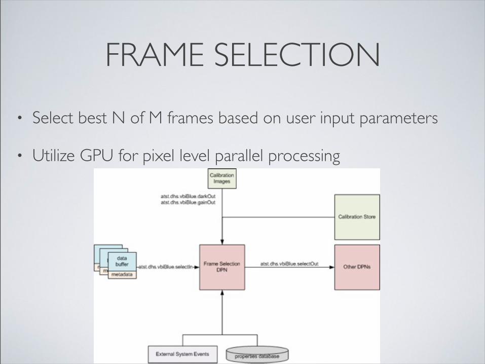
FRAME SELECTION
• Select best N of M frames based on user input parameters
• Utilize GPU for pixel level parallel processing

DETAILED DISPLAY• Calibrate frames
• Stitch frames during field sampling
• Utilize GPU for pixel level parallel processing

DATA DISTRIBUTION
• Data Transfer Node
• Saves raw data to camera store for 1 day [OCD 3.2]
• Data Distribution Node
• Collect data from transfer store + header store
• Deliver to Remote Operation Base

QUESTIONS

ATST Visible Broadband Imager
Project Schedule

CONSTRUCTION PHASE SCHEDULE
• The remaining parts will be ordered and fabricated after the CDR
• A new RFP will be issued for the VBI optics
• Filters are scheduled to arrive by Sept 30 - testing will begin as soon as spectrograph time is available at the Dunn Telescope
PRIMARY DEPENDENCIES
• Mini - DHS
• ICS
• Camera Software
• Camera Hardware
• Telescope
INSTRUMENT CONTROL SYSTEM (ICS)
• ICS components are critical to the development of the VBI software
• The ICS base components are complete
• The ICS Standard Instrument Framework (SIF) components will be finished Jan 2012
• The final ICS will be complete Feb 2015
• Jan-Mar 2016 is scheduled for VBI ICS integration

DATA HANDLING SYSTEM (DHS)
• The mini-DHS (with mini display tool) will be provided in Aug 2012 and is designed to handle a 960MBs data stream, one camera line, and will display and store the data at 5 to 10 fps with about 2 hours of total storage time
• The mini DHS will be upgraded with QA and the Data Processing Pipeline in Mar 2013
• Beginning in mid-2012, 10% of the DHS engineer’s time will be devoted to assisting instrument designers

SOFTWARE DEVELOPMENT
• Software development will take 11 (month) FTEs.
• Software development will begin following the delivery of:• Observatory Control System UIs• Mini Data Handling System• ICS base components• ICS Standard Instrument Framework
• The near-real-time speckle development will begin following the software development and is estimated at 5.5 FTE.

INSTRUMENT ASSEMBLY
• Instrument assembly will begin after :
• Control system build and test
• Parts fabrication
• Filter delivery
• Filter and optics testing

SYSTEM TEST / VERIFICATION
• System test will begin after :
• Mini DHS data processing pipeline enters testing.
• ICS enters final testing
• Development camera and camera software is available

FINAL CAMERA AVAILABLE
• When the visible light camera procurement is complete, integration of the final camera into the instrument will begin.

INSTALL AND SELF TEST
• The installation of the VBI into the ATST coude lab will begin after :
• DHS complete
• Coude lab complete
• Camera hardware is complete
• Telescope is available for wave-front-correction installation

ALIGNMENT & CALIBRATION
• Alignment and calibration of the VBI will begin after :
• The Observatory Control System is complete.
• The Instrument Control System is complete.
• All other telescope systems have reached the milestone of Engineering #2.

MISC. MILESTONES
• The speckle plug-in performance testing will begin when the NIRSP enters engineering phase 1.
• The VBI will begin project acceptance when the telescope enters engineering phase 3.
• The VBI and NIRSP will be tested together when the NIRSP is ready.

ATST Visible Broadband Imager
QA / QC Plan

HAZARD ANALYSIS

QA/QC PLAN
• Quality Control
• Verification
• Evaluate whether a product meets specifications, regulation, or standards set forth.
• Are you building it right?
• Quality Assurance
• Validation
• Establish evidence the provides proof the product accomplishes intended requirements.
• Are you building the right thing?

QUALITY CONTROL• Requirements Verification
• New and changed elements will be verified as related to the requirements• Process conducted by formal review of DRD by work package PI, manager, responsible engineer
• Design Verification• New and changed elements will be verified as related to the design• Process conducted by formal review of CDD by work package PI, manager, responsible engineer,
engineer from different work package
• As-Built Verification• New and changed components will be verified once construction is complete• Process conducted by informal review and sign off by work package manager and engineer from
different work package• Software Specific Tasks
• Software coding, commenting, best practice standards are met per SPEC-0005
• Document Verification• New and changed component documentation (DRD, CDD, etc.) provided/updated• Documentation review process conducted by informal review by ATST QA/QC representative and
release manager

QUALITY ASSURANCE
• Unit Testing• Testing of individual units to ensure they are fit for use before component level testing• Performed by responsible work package engineer
• Component Testing• Testing of the VBI sub-system as a whole before integration testing• Performed by responsible work package engineer
• Integration Testing• Testing to ensure integration with other ATST systems before acceptance testing• Performed by responsible work package engineer• Signed off by work package manager and engineer• Software Specific Tasks
• Software defects identified are logged in JIRA tracking system.• Test cases impacted are re-tested once defect is resolved.• Unresolved defects are approved by review team before proceeding to acceptance testing• Upon successful completion of testing, source code is tagged in CVS as part of a release. Test
documentation will reference the release number.

QUALITY ASSURANCE
• User Acceptance Testing• Testing for valid output of a system in a qualified test environment• Approved by work package PI, manager, and responsible engineer• Software Specific Tasks
• Only software source code from CVS tag matching that approved in acceptance testing• Software defects found in testing are logged in JIRA tracking system• Test cases impacted by defect are re-tested once defect is resolved• Unresolved defects must be approved before proceeding to production release• Test documentation includes reference to CVS tag for this release
• ATST IT&C• System will proceed to IT&C process after completing internal UAT

FABRICATION PLAN
VBI fabrication will occur at NSO/SP instrument labs in Sunspot, NM
Optics, mechanical and electrical parts ordered from and shipped to Sunspot
Assembly, wiring, testing and initial verification will take place in Sunspot
Filter alignment and verification will be done on NSO/SP spectrograph
Final documents and drawings will be placed into ATST configuration control system

TRANSPORTATION PLAN
VBI assembled, tested and verified, making use of available facilities
Optics benches shipped directly from manufacturer to Maui
Mounts, stages and electronics shipped via air freight from Sunspot to Maui
Optical elements packed and hand carried from Sunspot to ATST site
ATST Visible Broadband Imager
VBI Verification Plan

VERIFICATION (OFF-SITE)Optics• Mirrors [Interferometer]• Lenses [Interferometer]• Filters [Spectrograph, Imaging Setup]• Alignment Plan [Artificial Light Source]• Overall Performance of Optical System
[Artificial Light Source]Mechanics• Filterwheel• Camera stages• Lens stages / holders• Mirror mountsCamera• Camera tested by the ATST Camera
project
• Software• QA/QC procedure (as previously seen)
will continuously ensure proper functionality thought unit/component testing
• Focus procedure• Alignment procedure• Field Sampling procedure• Engineering GUI:• All motorized mechanical elements
must be adjustable and functional/operational through both high and low level inputs.
• All relevant camera settings must be adjustable and functional/operational through both high and low level inputs.
• All Plug-In parameters must be adjustable and functional/operational.

VERIFICATION (ON-SITE)ISRD Requirement Personel Procedure Success CriterionSpectral Range NSO
instrument scientist,operator
Pointing ATST to the center of the Sun, images of the solar atmosphere are to be acquired at all initial VBI wavelengths, with the adaptive optic system operational. In addition, dark and flat calibration images are to be acquired.Images are to be calibrated using the dark and flat calibration images.
Photon flux:within 5% of the expected photon flux (considering all optical elements and their characteristics).
Example 1: Spectral Range

ISRD Requirement Personel Procedure Success CriterionSignal-to-Noise Ratio NSO instrument
scientist,operator
Pointing ATST to the center of the Sun, images of the solar atmosphere are to be acquired at all initial VBI wavelengths, with the adaptive optic system operational. In addition, dark and flat calibration images are to be acquired.For each wavelength, the dark calibration image and gain calibration image is computed. The flat images are subsequently gain corrected. From the gain corrected flat images, a mean spatial power spectrum is computed, and azimuthally averaged. The high spatial frequency tail is a good estimate for the noise in the images.A comparison of this value to the azimuthally averaged spatial power spectrum of a single calibrated image serves as metric for the signal-to-noise ratio in the image.
Signal to Noise Ratio:within the required 100:1
VERIFICATION (ON-SITE)
Example 2: Signal-to-Noise Ratio

OUTLINE OF ASCIENCE VERIFICATION PLAN
1. What should be tested1.1. Usage performance (requirements flow from VBI OCD SPEC-0106)
1.1.1. operability / usability1.1.1.1. Quality Assurance1.1.1.2. Instrument Status Feedback
1.1.2. repeatability / stability1.2. Delivered algorithms for removal of instrument signature1.3. Assure Scientific Value of the instrument data
2. How should it be tested2.1. plan of
2.1.1. who (test driver e.g. RA, instrument scientist, not instrument builders) performs2.1.2. what action2.1.3. when2.1.4. using a readily available solar target (quiet sun, limb, …)
2.2. several days worth of observational data2.3. instrument scientist performs test for trends etc off-mountain
2.3.1. distributions of properties (granular sizes, motions, etc)2.3.2. looking for spurious trends in data sets
2.4. Possibly cross-calibration against other data

VBI WORKFLOW AT ATST

SCIENCE VERIFICATION – STEP A
Verification Step A:photospheric wavelengths
NSO instrument scientist,operator
Pointing ATST to the center of the Sun, images of the solar atmosphere are to be acquired at all initial photospheric VBI wavelengths, with the adaptive optic system operational.The complete VBI initialization workflow is to be tested at the beginning of each observation.Images are reconstructed. With potential intermediate reboots/shutdowns, time sequences of increasing duration intervals (1h, 2h, 4h, 8h) are acquired.If possible, similar co-temporal and co-spatial observations (using twin passbands) should be scheduled at another telescope.
During observation:- Ensure proper functionality of all used systems.- Ensure that no gain correction errors appear in the time sequences (optical stability).- Ensure that contrast/SNR does not show different behavior in the several observed time sequences.Offline:- Compute distribution in granular sizes and ensure compatibility with published results.- Compute granular contrast (potentially of spatially degraded data) and ensure compatibility with published results.

Verification Step B:chromospheric wavelengths
NSO instrument scientist,operator
Pointing ATST to the limb of the Sun, images of the solar atmosphere are to be acquired at all initial chromospheric VBI wavelengths, with the adaptive optic system operational.The complete VBI initialization workflow is to be tested.Frame Selection Plugin is used. A time sequence of 6h is acquired, with exposures synchronized to the modulator.If possible, similar co-temporal and co-spatial observations (using twin passbands) should be scheduled at another telescope.
During observation:- Ensure proper functionality of all used systems- Ensure non-existence of systematic intensity fluctuations due to imperfect synchronization to modulator.Offline:- Compute distribution of length and diameter of spicules and ensure compatibility with published results.
SCIENCE VERIFICATION – STEP B

IT&C PLAN
• Please see IT&C schedule print

ATST Visible Broadband Imager
Budget

CONSTRUCTION BUDGET

FINAL DESIGN LABOR
PDR Estimates as
presented
Final Design VBI
Team
Final Design
Contractor
Final Design Total
Difference
US$214,447 US$159,248 US$1,950 US$161,197.72-US$53,249.29
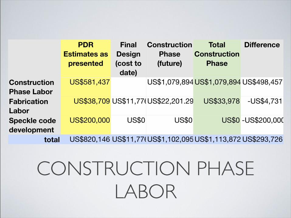
CONSTRUCTION PHASE LABOR
PDR Estimates as
presented
Final Design (cost to
date)
Construction Phase (future)
Total Construction
Phase
Difference
Construction Phase LaborFabrication LaborSpeckle code development
total
US$581,437 US$1,079,894US$1,079,894 US$498,457
US$38,709 US$11,776US$22,201.29 US$33,978 -US$4,731
US$200,000 US$0 US$0 US$0 -US$200,000
US$820,146 US$11,776US$1,102,095US$1,113,872 US$293,726

CONSTRUCTION PHASE NON-LABOR
PDR Estimates as presented
Final Design (encumbrances to
date)
Construction Phase
(planned)
Total (since PDR)
Difference
Optics - lenses / mirrorsFilters
Mechanical - mounts, filter wheel, stages
Controls and misc.
Mechanical - spares
Benches
Thermal
total
US$97,842 US$0 US$97,842 US$97,842 US$0
US$115,748 US$82,958 US$20,000 US$102,958-US$12,790
US$26,996 US$14,115 US$12,851 US$26,966 -US$30
US$166,990 US$57,735 US$120,524US$178,259US$11,269
US$14,960 US$18,300 US$18,300 US$3,340
US$12,480 US$12,480 US$12,480 US$0
US$10,000 US$1,102 US$1,102 -US$8,898
US$445,016 US$154,808 US$283,099US$437,907-US$7,109

CONSTRUCTION PHASE TOTALS
PDR Estimates as presented
Total (since PDR) Difference
totals US$1,265,162 US$1,551,779 US$286,617

FILTERS
Filter wavelength CDR cost
HβCa II K
G-band
Blue Continuum
total
486.1 US$40,985
393.34 US$23,394
430.5 US$9,238
450.0 US$9,341
US$82,958

OPTICS
Optic price tooling total cost
Field Lens
Collimator Lens
Image Lens
Objective Lens
400mm Flat Mirror
100mm Flat Mirror
2nd objective lens
total
US$3,078 US$608 US$3,686
US$6,750 US$5,265 US$12,015
US$12,623 US$608 US$13,231
US$39,881 US$720 US$40,601
US$13,984 US$13,984
US$1,094 US$1,094
US$12,623 US$608 US$13,231
US$97,842

MECHANICAL
Spent Future
Labor
Parts
total
US$16,508 US$22,201
US$14,115 US$12,851
US$30,623 US$35,052

SPARES
Delta Tau Power PMACDelta Tau ACC-24E3 PWM ampDelta Tau ACC-84E serial interfaceDelta Tau ACC-36E A/D boardDelta Tau ACC-65E I/O boardDelta Tau ACC-R2 UMAC rackDelta Tau 3U081 Single axis 8A amplifierDelta Tau 3U042 Dual axis 4A amplifierParker 404100XRMP linear stageParker SM232AL-NPSN servo motorAerotech S76-149-A slotless motorCopely JSP-090-10Asco SD8202G051VTotal
US$4,375US$1,300
US$657US$740US$525
US$1,175US$1,430US$2,630US$2,816
US$965US$1,085
US$296US$306
US$18,300

CONTROLS & MISC.
Camera
Electrical (from electrical sheet)
Final Instrument Computer
Tools / test equipment
Software / licenses
total
project
US$7,195
US$3,329
US$100,000
US$10,000
US$120,524
Delta Tau & test equipment encumbered US$57,735

ELECTRICAL
Electronics (from electrical BOM)PCB fabPower dist. chassisFilter wheel cablesEncoder cablesPower cablingPower connectorsEthernet cablingSwitch enclosureTerminalsWiringDist. status cablesTotal
US$3,462US$400
US$1,200US$338US$120US$346US$180
US$46US$63
US$120US$825
US$95US$7,195

THERMAL
part number cost
Proportioning valve
Electronic valve control
Coolant lines, valves, fittings
Camera thermal control systemtotal
Asco SD8202G051V US$306
Copely JSP-090-10 US$296
misc. US$500
project provided US$0
US$1,102

TechnicalTechnical CostCost ScheduleSchedule Contingency Baseline Contingency
Construction phase labor
Construction phase encumb.Speckle code development
Lenses/Mirrors
Filters
Filters encumb.
Mechanical - optics mounts, filter wheel, stagesMechanical encumb.
Rack, electrical distribution
Computers
Tools, test equipment
Software / licenses
Controls / test equip encumb.
Spares
Benches
Thermal control
Tech Fact Cost Fact Schd Fact %4 2 6 1 4 1 18 US$947,761 US$170,597
US$11,7766 4 6 1 2 1 32 US$154,334 US$49,387
4 4 4 2 2 1 26 US$97,842 US$25,439
8 4 3 2 2 1 40 US$20,000 US$8,000
US$82,958
4 4 3 2 2 124
US$12,851 US$3,084
US$14,115
1 2 1 1 2 1 5 US$7,195 US$360
1 2 1 1 2 1 5 US$3,329 US$166
1 2 4 1 2 1 8 US$100,000 US$8,000
1 2 4 1 2 1 8 US$10,000 US$800
US$57,735
1 2 1 1 2 1 5 US$18,300 US$915
1 2 1 1 2 1 5 US$12,480 US$624
2 2 2 2 2 1 10 US$1,102 US$110
US$1,551,779US$267,482
total US$1,819,261