ATSC Candidate Standard: Signaling, Delivery ... · A.4.6 Repair Protocol 108 A.5 Security...
143
S33-174r3 Signaling, Delivery, Synchronization, and Error Protection 21 June 2016 i ATSC Candidate Standard: Signaling, Delivery, Synchronization, and Error Protection (A/331) Doc S33-174r3 21 June 2016 Advanced Television Systems Committee 1776 K Street, N.W. Washington, D.C. 20006 202-872-9160
Transcript of ATSC Candidate Standard: Signaling, Delivery ... · A.4.6 Repair Protocol 108 A.5 Security...

S33-174r3 Signaling, Delivery, Synchronization, and Error Protection 21 June 2016
i
ATSC Candidate Standard: Signaling, Delivery, Synchronization,
and Error Protection (A/331)
Doc S33-174r3 21 June 2016
Advanced Television Systems Committee 1776 K Street, N.W. Washington, D.C. 20006 202-872-9160

S33-174r3 Signaling, Delivery, Synchronization, and Error Protection 21 June 2016
ii
The Advanced Television Systems Committee, Inc., is an international, non-profit organization developing voluntary standards for digital television. The ATSC member organizations represent the broadcast, broadcast equipment, motion picture, consumer electronics, computer, cable, satellite, and semiconductor industries.
Specifically, ATSC is working to coordinate television standards among different communications media focusing on digital television, interactive systems, and broadband multimedia communications. ATSC is also developing digital television implementation strategies and presenting educational seminars on the ATSC standards.
ATSC was formed in 1982 by the member organizations of the Joint Committee on InterSociety Coordination (JCIC): the Electronic Industries Association (EIA), the Institute of Electrical and Electronic Engineers (IEEE), the National Association of Broadcasters (NAB), the National Cable Telecommunications Association (NCTA), and the Society of Motion Picture and Television Engineers (SMPTE). Currently, there are approximately 120 members representing the broadcast, broadcast equipment, motion picture, consumer electronics, computer, cable, satellite, and semiconductor industries.
ATSC Digital TV Standards include digital high definition television (HDTV), standard definition television (SDTV), data broadcasting, multichannel surround-sound audio, and satellite direct-to-home broadcasting.
Note: The user's attention is called to the possibility that compliance with this standard may require use of an invention covered by patent rights. By publication of this standard, no position is taken with respect to the validity of this claim or of any patent rights in connection therewith. One or more patent holders have, however, filed a statement regarding the terms on which such patent holder(s) may be willing to grant a license under these rights to individuals or entities desiring to obtain such a license. Details may be obtained from the ATSC Secretary and the patent holder.
This specification is being put forth as a Candidate Standard by the TG3/S33 Specialist Group. This document is a revision of the Working Draft (S33-174r0) dated 8 December 2015. All ATSC members and non-members are encouraged to review and implement this specification and return comments to [email protected]. ATSC Members can also send comments directly to the TG3/S33 Specialist Group. This specification is expected to progress to Proposed Standard after its Candidate Standard period.
Revision History
Version Date Candidate Standard approved 5 January 2016 Updated CS approved 21 June 2016 Cyan highlight and text in blue italics identify areas that are under development in the committee. Feedback and comments on these points from implementers is encouraged.
Standard approved Insert date here

S33-174r3 Signaling, Delivery, Synchronization, and Error Protection 21 June 2016
iii
Table of Contents 1. SCOPE ..................................................................................................................................................... 1
1.1 Introduction and Background 1 1.2 Organization 1
2. REFERENCES ......................................................................................................................................... 1 2.1 Normative References 2 2.2 Informative References 4
3. DEFINITION OF TERMS .......................................................................................................................... 4 3.1 Compliance Notation 4 3.2 Treatment of Syntactic Elements 5
Reserved Elements 5 3.3 Acronyms and Abbreviation 5 3.4 Terms 7 3.5 Extensibility 9 3.6 XML Schema and Namespace 10
4. SYSTEM OVERVIEW ............................................................................................................................. 10 4.1 System Conceptual Model 10 4.2 Features 11
5. SERVICE SIGNALING OVERVIEW ....................................................................................................... 12 5.1 Receiver Protocol Stack 12 5.2 Entity Relationships and Addressing Architecture 13 5.3 Service Types 13
6. LOW LEVEL SIGNALING ...................................................................................................................... 15 6.1 IP Address Assignment 15 6.2 LLS Table Format 16 6.3 Service List Table (SLT) 17
SLT Syntax Description 18 SLT Semantics 20
6.4 System Time Fragment 22 6.5 Common Alerting Protocol Message 24 6.6 Broadband Delivery of Signaling Metadata 24
7. SERVICE LAYER SIGNALING .............................................................................................................. 26 7.1 ROUTE/DASH Service Layer Signaling 28
Streaming Content Signaling 29 App-based Enhancement Signaling 30 User Service Description 30
7.1.3.1 User Service Description for ROUTE – Semantics 31 Service-based Transport Session Instance Description (S-TSID) 33 Media Presentation Description (MPD) 35
7.1.5.1 Delivery Path Signaling 36 7.1.5.2 Signaling for Staggercast Audio Representation 36 7.1.5.3 Content ID for Content in ROUTE/DASH Services 37
Service Signaling Delivery 37 7.1.6.1 Signaling Description Encapsulation 37
S33-174r3 Signaling, Delivery, Synchronization, and Error Protection 21 June 2016
iv
7.1.6.2 Signaling Description Filtering 37 Associated Procedure Description (APD) 38
7.1.7.1 APD Semantics 39 7.1.7.2 End of File Transmission and Start of File Repair Procedure 39
7.2 MMT Service Layer Signaling 39 User Service Description for MMT 40
7.2.1.1 User Service Description for MMT – Semantics 44 Media Presentation Description (MPD) 47 MMT Signaling Message 47
7.2.3.1 mmt_atsc3_message() MMT Signaling Message 48 7.2.3.2 Video Stream Properties Descriptor 50
7.2.3.2.1 Syntax 50 7.2.3.2.1.1 Scalability Information 52 7.2.3.2.1.2 MultiView Information 53 7.2.3.2.1.3 Resolution, Chroma Format, Bit-depth and Video Properties
Information: 54 7.2.3.2.1.4 Picture Rate Information 54 7.2.3.2.1.5 Bit Rate Information 55 7.2.3.2.1.6 Color Information 55
7.2.3.3 ATSC Staggercast Descriptor 56 7.3 Content Advisory Ratings in Service Signaling 57
DASH Signaling of RRT-based Content Advisories 57 MMT Signaling of RRT-Based Content Advisories 60
8. DELIVERY AND AL-FEC ....................................................................................................................... 60 8.1 Broadcast Delivery 60
ROUTE/DASH 60 8.1.1.1 Streaming Services Delivery 60 8.1.1.2 Locally-Cached Content Delivery 61 8.1.1.3 Synchronization and Time 62 8.1.1.4 ROUTE/DASH System Model 62 8.1.1.5 ROUTE System Buffer Model 64
8.1.1.5.1 Data Delivery Event (DDE) 64 8.1.1.5.2 Media Delivery Event (MDE) 65 8.1.1.5.3 ROUTE Transport Buffer Model 66
8.1.1.6 Application of AL-FEC (Informative) 67 MMTP/MPU 68
8.1.2.1 Broadcast Streaming Delivery of ISO BMFF Files 68 8.1.2.1.1 Mapping Between an ATSC 3.0 Service and MMT Packages 68 8.1.2.1.2 Constraints on MPU 69 8.1.2.1.3 Constraints on MMTP 69
8.1.2.2 Packetization of MPU 71 8.1.2.3 Synchronization 72 8.1.2.4 Delivery of Locally-Cached Service Content 72 8.1.2.5 AL-FEC 73
8.2 Hybrid (Broadcast/Broadband) Delivery 73 ROUTE/DASH Modes of Hybrid Service Access 73
8.2.1.1 Synchronization 73 8.2.1.2 Broadband DASH-only Service Access 74

S33-174r3 Signaling, Delivery, Synchronization, and Error Protection 21 June 2016
v
8.2.1.2.1 Exclusive Delivery of Service Components via Broadband 74 8.2.1.2.2 Hand-off from Broadcast to Broadband Service Access 74
MMTP/MPU Modes of Hybrid Service Access 75 8.2.2.1 Introduction 75 8.2.2.2 Constraints on DASH 75 8.2.2.3 Synchronization 76 8.2.2.4 Acquisition 76 8.2.2.5 Broadband-Only Service (Signaled by Broadcast) 76
8.2.2.5.1 Zero Components Delivered by Broadcast 76 8.3 File Repair Procedure 76
File Repair for Receivers that are not AL-FEC Capable 77 File Repair for Receivers that are AL-FEC capable 77 Repair Server Location and Response Deadline 78
ANNEX A : ROUTE ....................................................................................................................................... 79 A.1 OVERVIEW of ROUTE 79
A.1.1 General 79 A.1.2 Source Protocol 79 A.1.3 Repair Protocol 79 A.1.4 Features 80 A.1.5 System Architecture 80
A.2 Data Model and Session Initiation 82 A.2.1 Data Model 82 A.2.2 ROUTE Session 82 A.2.3 Transport Sessions 83
A.3 Source Protocol Specification 83 A.3.1 Overview 83 A.3.2 Description 83
A.3.2.1 Source Flow Semantics 84 A.3.3 Delivery Objects 86
A.3.3.1 Overview 86 A.3.3.2 File Mode 86 A.3.3.3 Entity Mode 91 A.3.3.4 Packaging 91
A.3.4 Usage of ALC and LCT 91 A.3.5 Packet Format 92 A.3.6 LCT Building Block 93 A.3.7 Extension Headers 94
A.3.7.1 Introduction 94 A.3.7.2 EXT_ROUTE_PRESENTATION_TIME Header 94 A.3.7.3 EXT_TIME Header 94
A.3.8 Basic ROUTE Sender Operation 95 A.3.9 Basic ROUTE Receiver Operation 95
A.3.9.1 Overview 95 A.3.9.2 Basic Delivery Object Recovery 96 A.3.9.3 General Metadata Recovery 97 A.3.9.4 Packaged Mode Reception 97
A.4 Repair Protocol Specification 98 A.4.1 Introduction 98

S33-174r3 Signaling, Delivery, Synchronization, and Error Protection 21 June 2016
vi
A.4.2 FEC Protocol 98 A.4.2.1 Introduction 98 A.4.2.2 FEC transport object construction 99 A.4.2.3 Super-Object and FEC repair for delivery objects 100 A.4.2.4 Repair Packet Structure 101 A.4.2.5 Summary FEC Information 101 A.4.2.6 Extension Headers 102
A.4.3 Repair Flows Declaration 102 A.4.3.1 General 102 A.4.3.2 Semantics 102 A.4.3.3 TOI Mapping 103 A.4.3.4 Examples for RepairFlow Declarations 104
A.4.4 Receiver Operation 106 A.4.4.1 Introduction 106
A.4.5 Example Operation 108 A.4.6 Repair Protocol 108
A.5 Security Considerations 108 ANNEX B : SIGNALING INSTANCE EXAMPLES ...................................................................................... 109
B.1 ROUTE Hierarchy Signaling Structure 109 B.2 Fast Service Scan 109 B.3 ROUTE Full Service Scan 110 B.4 Service Acquisition in the Pure Broadcast (One ROUTE Session) 111 B.5 Service Acquisition in the Pure Broadcast (Multiple ROUTE Sessions) 112 B.6 ESG Bootstrapping via Broadband 113 B.7 ROUTE Hybrid (Multiple Audio Language) 114 B.8 Handoff (Broadcast to Broadband, and Back) 115 B.9 Scalable Coding (Capability in the USD) 116 B.10 SLT Delivery Path 117 B.11 Multiple SLTs in a Broadcast Stream 118
ANNEX C : FILTERING FOR SIGNALING FRAGMENTS .......................................................................... 120 ANNEX D : TEMPLATE-BASED COMPRESSION ..................................................................................... 122
D.1 Diff and Patch Operation 122 D.2 Diff Representation 123 D.3 Template pre-sharing 123
ANNEX E : ACQUISITION AND PLAYBACK OF SERVICE USING MMTP .............................................. 124 E.1 Introduction 124 E.2 Mapping Between the Physical Layer and MMTP Sessions 124 E.3 Service Acquisition 125
ANNEX F : RATING REGION TABLE REQUIREMENTS ........................................................................... 128 F.1 Introduction 128 F.2 RRT Requirements 128
ANNEX G : EMERGENCY ALERT SIGNALING ......................................................................................... 130 G.1 Emergency Alert System Structure 130
G.1.1 Overview of the System 130 G.1.2 Flow of Emergency Alert Signaling and Rich Media Contents 131

S33-174r3 Signaling, Delivery, Synchronization, and Error Protection 21 June 2016
vii
G.2 Meaning of Wake-Up bits 132 G.3 Emergency Alert System Operation 133 G.4 Common Alerting Protocol (CAP) 133
G.4.1 CAP Message Delivery 133 G.4.2 Rich Media Content 133

S33-174r3 Signaling, Delivery, Synchronization, and Error Protection 21 June 2016
viii
Index of Figures and Tables Figure 4.1 Conceptual protocol stack. ......................................................................................... 11 Figure 5.1 ATSC 3.0 receiver protocol stack. .............................................................................. 12 Figure 5.2 Service List Table references to Services. .................................................................. 13 Figure 5.3 UML Diagram showing relationships among Service Management,
Delivery, and Physical Layer entities. ................................................................................... 13 Figure 7.1 Example use of service signaling for bootstrapping and service discovery. .............. 28 Figure 7.2 Service Layer Signaling data model for Linear Services. .......................................... 29 Figure 7.3 Service Layer Signaling data model for Linear Services. .......................................... 40 Figure 8.1 ROUTE/DASH system model. ................................................................................... 63 Figure 8.2 Concept of an MDE data block starting with a RAP. ................................................. 65 Figure 8.3 Illustration of an MDE data block at the video level. ................................................. 66 Figure 8.4 ROUTE transport buffer model. ................................................................................. 66 Figure 8.5 An MMT package delivered over a single MMTP packet flow. ................................ 69 Figure 8.6 An MMT package delivered over two MMTP packet flows. ..................................... 69 Figure 8.7 Receiver buffer model consuming MMTP sessions. .................................................. 71 Figure 8.8 Example of media aware packetization of MPU. ....................................................... 72 Figure 8.9 ROUTE/DASH hybrid synchronization. .................................................................... 73 Figure 8.10 Conceptual hybrid service architecture. ................................................................... 75 Figure A.1.1 Reference receiver architecture model in ROUTE. ................................................ 81 Figure A.1.2 Sender operation of ROUTE protocol. ................................................................... 82 Figure A.3.1 ROUTE Distribution in file mode compared to FLUTE distribution. .................... 87 Figure A.3.2 Overall ROUTE packet format. .............................................................................. 93 Figure A.3.3 12-byte EXT_ROUTE_PRESENTATION_TIME header. ..................................... 94 Figure A.3.4 Receiver operation. ................................................................................................. 96 Figure A.4.1 FEC packet generation. ........................................................................................... 99 Figure A.4.2 FEC transport object construction (example with S = 3). .................................... 100 Figure A.4.3 EXT_TOL Header (24-bit version shown on top and 48-bit version
shown on bottom). ............................................................................................................... 102 Figure A.4.4 RepairFlow example #1. .................................................................................. 104 Figure A.4.5 RepairFlow example #2. ................................................................................ 105 Figure A.4.6 RepairFlow example #3. ................................................................................ 105 Figure A.4.7 RepairFlow example #4. .................................................................................. 106 Figure A.4.8 RepairFlow example #5. .................................................................................. 106 Figure A.4.9 ROUTE receiver with FEC. .................................................................................. 107 Figure B.1.1 ATSC 3.0 ROUTE hierarchical signaling architecture. ........................................ 109 Figure B.2.1 Fast service scan signaling flow. .......................................................................... 110 Figure B.3.1 ROUTE full-service scan signaling flow. ............................................................. 111 Figure B.4.1 Service acquisition in the pure broadcast (one ROUTE session). ........................ 112 Figure B.5.1 Service acquisition in the pure broadcast (multiple ROUTE sessions). ............... 113 Figure B.6.1 ROUTE ESG bootstrapping via broadband. ......................................................... 114 Figure B.7.1 ROUTE hybrid (multiple audio languages). ......................................................... 115 Figure B.8.1 Handoff (broadcast to broadband, and back). ....................................................... 116 Figure B.9.1 Scalable coding (capability in USD). .................................................................... 117 Figure B.10.1 ROUTE SLT delivery path. ................................................................................ 118 Figure B.11.1 Multiple SLTs. .................................................................................................... 119

S33-174r3 Signaling, Delivery, Synchronization, and Error Protection 21 June 2016
ix
Figure C.1 Example for TOI bit assignment. ............................................................................. 120 Figure D.1.1 Template based signaling fragment compression. ................................................ 123 Figure E.2.1 A PHY channel consisting of two PLPs. .............................................................. 125 Figure E.3.1 MPU broadcast streaming channel change. .......................................................... 126 Figure G.1.1 High level architecture of an Emergency Alert system. ....................................... 130 Figure G.1.2 Emergency Alert data flows. ................................................................................ 131 Table 6.1 Common Bit Stream Syntax for LLS Tables ............................................................... 17 Table 6.2 SLT XML Format (next page) ..................................................................................... 18 Table 6.3 Code Values for urlType .......................................................................................... 20 Table 6.4 Code Values for SLT.Service@serviceCategory ......................................... 21 Table 6.5 Code Values for SLT.Service.BroadcastSvcSignaling@slsProtocol
............................................................................................................................................... 22 Table 6.6 SystemTime Element Structure ................................................................................ 23 Table 6.7 Daylight Saving Signaling Throughout the Year ......................................................... 24 Table 6.8 Path Terms, in Order of Appearance in Path ............................................................... 25 Table 6.9 Metadata Object Types ................................................................................................ 25 Table 7.1 Semantics of the User Service Bundle Description Fragment for ROUTE/DASH ..... 31 Table 7.2 Semantics of the Service-based Transport Session Instance Description Fragment .... 34 Table 7.3 AssetIdentifier Attribute Values for Content ID .......................................................... 37 Table 7.4 Semantics of the Associated Procedure Description Fragment ................................... 39 Table 7.5 XML Format of the User Service Bundle Description Fragment for MMT ................ 42 Table 7.6 Bit Stream Syntax for mmt_atsc3_message() ......................................................... 48 Table 7.7 Code Values for atsc3_message_content_type ..................................................... 49 Table 7.8 Code Values for atsc3_message_content_compression ...................................... 49 Table 7.9 Bit Stream Syntax for Video Stream Properties Descriptor ......................................... 50 Table 7.10 Bit Stream Syntax for Scalability Information........................................................... 52 Table 7.11 Bit Stream Syntax for Multi-View Information ......................................................... 53 Table 7.12 Bit Stream Syntax for Resolution, Chroma Format, Bit-Depth ................................. 54 Table 7.13 Bit Stream Syntax for Picture Rate Information ........................................................ 54 Table 7.14 Bit Stream Syntax for Bit Rate Information .............................................................. 55 Table 7.15 Bit Stream Syntax for Color Information................................................................... 56 Table 7.16 Bit Stream Syntax for ATSC Staggercast Descriptor ................................................ 57 Table 7.17 Example Content Advisory Rating Strings ................................................................ 59 Table A.3.1 Semantics of SrcFlow Element ............................................................................. 84 Table A.3.2 Meaning of DeliveryObjectFormatID Values ............................................. 86 Table A.3.3 Extended File Delivery Table Semantics ................................................................. 88 Table A.3.4 Identifiers for File templates .................................................................................... 91 Table A.4.1 Semantics of RepairFlow Element .................................................................... 103 Table A.4.2 Protected Object Bundle ......................................................................................... 103 Table C.1 Fragment Type Values .............................................................................................. 120 Table C.2 Fragment Type Extension Values ............................................................................. 121 Table F.2.1 RatingRegionTables Element Structure ....................................................... 129 Table F.2.2 TextType Element Structure ............................................................................... 129 Table G.2.1 Meaning of Wake-up Bits ...................................................................................... 132

S33-174r3 Signaling, Delivery, Synchronization, and Error Protection 21 June 2016
1
ATSC Candidate Standard: Signaling, Delivery, Synchronization,
and Error Protection
1. SCOPE This document specifies protocols used for delivery and synchronization of media and non-timed data in the ATSC 3.0 system.
1.1 Introduction and Background This document specifies the technical mechanisms and procedures pertaining to service signaling and IP-based delivery of a variety of ATSC 3.0 services and contents to ATSC 3.0-capable receivers over broadcast, broadband and hybrid broadcast/broadband networks. The service signaling functionality defines the data formats and information components necessary to discover and acquire user services. The IP-based delivery functionality specifies two application transport protocols for the carriage of media content and service signaling data over broadcast and/or broadband networks to receivers. The delivery functionality also includes mechanisms for the synchronization of media components delivered on the same or different transport networks, and application-layer forward error correction methods that enable error-free reception and consumption of media streams or discrete file objects.
1.2 Organization This document is organized as follows:
• Section 1 – Scope and organization • Section 2 – Lists references and applicable documents. • Section 3 – Provides a definition of terms, acronyms, and abbreviations for this
document. • Section 4 – System overview • Section 5 – Service signaling overview • Section 6 – Specification of low-layer signaling • Section 7 – Specification of service-layer signaling • Section 8 – Specification of delivery, synchronization, and AL-FEC • Annex A – Real-time Object delivery over Unidirectional Transport (ROUTE) • Annex B – Signaling instance examples • Annex C – Filtering for signaling fragments • Annex D – Template-based compression • Annex E – Acquisition and Playback of Service Using MMTP • Annex F – Rating Region Table Requirements • Annex G – Emergency Alert Signaling
2. REFERENCES All referenced documents are subject to revision. Users of this Standard are cautioned that newer editions might or might not be compatible.

S33-174r3 Signaling, Delivery, Synchronization, and Error Protection 21 June 2016
2
2.1 Normative References The following documents, in whole or in part, as referenced in this document, contain specific provisions that are to be followed strictly in order to implement a provision of this Standard. [1] ATSC: “Program and System Information Protocol for Terrestrial Broadcast and Cable,”
Document A/65:2013, Advanced Television Systems Committee, 7 August 2013. [2] ATSC A/153 Part 4, “ATSC- Mobile DTV Standard, Part 4: Announcement”, Advanced
Television Systems Committee, October 2009. [3] ATSC: “Physical Layer Protocol,” Document A/322, Advanced Television Systems
Committee, under development. [4] ATSC: “Service Announcement,” Document A/332, Advanced Television Systems
Committee, under development. [5] ATSC: “Service Usage Reporting,” Document A/333, Advanced Television Systems
Committee, under development. [6] ATSC: “Captions and Subtitles,” Document A/343, Advanced Television Systems
Committee, under development. [7] CTA: “U.S. and Canadian Region Rating Tables (RRT) and Content Advisory Descriptors
for Transport of Content Advisory Information Using ATSC Program and System Information Protocol (PSIP),” Doc. CEA-766-D (ANSI), Consumer Technology Association, December 11, 2013.
[8] DASH IF: “Guidelines for Implementation: DASH-IF Interoperability Points, Version 3.1,” DASH Interoperability Forum.
[9] ETSI TS 126 346 v13.3.0 (2016-01), “Universal Mobile Telecommunications Systems (UMTS); LTE; Multimedia Broadcast/Multicast Service (MBMS); Protocols and codecs (3GPP TS 26.346 version 13.3.0 Release 13),” European Telecommunications Standards Institute, 2014.
[10] IEEE: “Use of the International Systems of Units (SI): The Modern Metric System,” Doc. SI 10-2010, Institute of Electrical and Electronics Engineers, New York, N.Y.
[11] IETF: RFC 1952, “GZIP file format specification version 4.3,” Internet Engineering Task Force, Reston, VA, May, 1996. http://tools.ietf.org/html/rfc1952
[12] IETF: RFC 2557, “MIME Encapsulation of Aggregate Documents, such as HTML (MHTML)”, Internet Engineering Task Force, Reston, VA, March 1999. http://tools.ietf.org/html/rfc2557
[13] IETF: RFC 2616, “Hypertext Transfer Protocol -- HTTP/1.1,” Internet Engineering Task Force, Reston, VA, June, 1999. http://tools.ietf.org/html/rfc2616
[14] IETF: RFC 2794, “Mobile IP Network Access Identifier Extension for IPv4,” Internet Engineering Task Force, Reston, VA, March, 2000. http://tools.ietf.org/html/rfc2794
[15] IETF: RFC 3023, “XML Media Types,” Internet Engineering Task Force, Reston, VA, January 2001. http://tools.ietf.org/html/rfc3023
[16] IETF: RFC 3986, “Uniform Resource Identifier (URI): Generic Syntax,” Internet Engineering Task Force, Reston, VA, January, 2005. http://tools.ietf.org/html/rfc3986
[17] IETF: RFC 4566, “SDP: Session Description Protocol,” Internet Engineering Task Force, Reston, VA, July 2006. http://tools.ietf.org/html/rfc4566
[18] IETF: RFC 5052, “Forward Error Correction (FEC) Building Block,” Internet Engineering Task Force, Reston, VA, August 2007. http://tools.ietf.org/html/rfc5052

S33-174r3 Signaling, Delivery, Synchronization, and Error Protection 21 June 2016
3
[19] IETF: RFC 5053, “Raptor Forward Error Correction Scheme for Object Delivery,” Internet Engineering Task Force, Reston, VA, October, 2007 http://tools.ietf.org/html/rfc5053
[20] IETF: RFC 5905, “Network Time Protocol Version 4: Protocol and Algorithms Specification,” Internet Engineering Task Force, Reston, VA, June, 2010. http://tools.ietf.org/html/rfc5905
[21] IETF: RFC 5261, “An Extensible Markup Language (XML) Patch Operations Framework Utilizing XML Path Language (XPath) Selectors,” Internet Engineering Task Force, Reston, VA, Sep, 2008. http://tools.ietf.org/html/rfc5261
[22] IETF: RFC 5445, “Basic Forward Error Correction (FEC) Schemes” Internet Engineering Task Force, Reston, VA, March, 2009. http://tools.ietf.org/html/rfc5445
[23] IETF: RFC 5651, “Layered Coding Transport (LCT) Building Block,” Internet Engineering Task Force, Reston, VA, October, 2009. http://tools.ietf.org/html/rfc5651
[24] IETF: RFC 5775, “Asynchronous Layered Coding (ALC) Protocol Instantiation,” Internet Engineering Task Force, Reston, VA, April, 2010. http://tools.ietf.org/html/rfc5775
[25] IETF: RFC 6330, “RaptorQ Forward Error Correction Scheme for Object Delivery,” Internet Engineering Task Force, Reston, VA, August, 2011. http://tools.ietf.org/html/rfc6330
[26] IETF: RFC 6726, “FLUTE - File Delivery over Unidirectional Transport,” Internet Engineering Task Force, Reston, VA, November, 2012. http://tools.ietf.org/html/rfc6726
[27] IETF: BCP 47, “Tags for Identifying Languages,” Internet Engineering Task Force, Reston, VA, September 2009. https://tools.ietf.org/html/bcp47
[28] ISO/IEC 13818-1 (2015), “Information Technology – Generic coding of moving pictures and associated audio – Part 1: Systems,” International Organization for Standardization.
[29] ISO/IEC 14496-15:2014/Cor 1:2015: Information technology -- Coding of audio-visual objects – Part 15: Carriage of network abstraction layer (NAL) unit structured video in ISO base media file format,” International Organization for Standardization.
[30] ISO/IEC: ISO/IEC 23008-1:201x, “Information technology — High efficiency coding and media delivery in heterogeneous environments — Part 1: MPEG media transport (MMT),” International Organization for Standardization, 2nd Edition, (publication expected October 2015).
[31] ISO/IEC: ISO/IEC 23008-2, “Information technology — High efficiency coding and media delivery in heterogeneous environments — Part 2: High Efficiency Video Coding,” International Organization for Standardization.
[32] ISO/IEC: ISO/IEC 8859, Information Processing — 8-bit Single-Octet Coded Character Sets, Parts 1 through 10.
[33] ISO: ISO 639-3:2007, “Codes for the representation of names of languages -- Part 3: Alpha-3 code for comprehensive coverage of languages,” http://www.iso.org/iso/catalogue_detail?csnumber=39534
[34] ITU: ITU-R Recommendation BT.709-5 (2002), “Parameter values for the HDTV standards for production and international programme exchange,” International Telecommunications Union, Geneva.
[35] OASIS: “Common Alerting Protocol” Version 1.2, 1 July 2010. http://docs.oasis-open.org/emergency/cap/v1.2/CAP-v1.2-os.pdf
[36] OMA: “Service Guide for Mobile Broadcast Services,” Version 1.0.1, document OMA-TS-BCAST_Service_Guide-V1_0_1-20130109-A, Open Mobile Alliance, 09 January 2013.

S33-174r3 Signaling, Delivery, Synchronization, and Error Protection 21 June 2016
4
[37] W3C: “W3C XML Schema Definition Language (XSD) 1.1 Part 2: Datatypes,” W3C Recommendation, Worldwide Web Consortium, 5 April 2012. https://www.w3.org/TR/xmlschema11-2/
2.2 Informative References The following documents contain information that may be helpful in applying this Standard. [38] ATSC: “Application Runtime Environment,” Document A/344:201x, Advanced Television
Systems Committee, Washington, D.C., [date], work in process. [39] ATSC: “Application Signaling and Triggers,” Document A/337:201x, Advanced Television
Systems Committee, Washington, D.C., [date], work in process. [40] 3GPP: TR 26.946 V13.1.0 (2014-12), “3rd Generation Partnership Project; Technical
Specification Group Services and System Aspects; Multimedia Broadcast/Multicast Service (MBMS) User service guidelines (Release 13).”
[41] ATSC: A/153, “ATSC-Mobile DTV Standard, Part 3 – Service Multiplex and Transport Subsystem.”
[42] IEEE: IEEE 1588-2008 PTP, “Standard for a Precision Clock Synchronization Protocol for Networked Measurement and Control Systems,”, Institute for Electrical and Electronics Engineers.
[43] IETF: RFC 2365, “Administratively Scoped IP Multicast,” Internet Engineering Task Force, Reston, VA, July 1998. http://tools.ietf.org/html/rfc2365
[44] IETF: RFC 6363, “Forward Error Correction (FEC) Framework,” Internet Engineering Task Force, Reston, VA, October, 2011. http://tools.ietf.org/html/rfc6363
[45] IETF: RFC 6968, “FCAST: Object Delivery for the Asynchronous Layered Coding (ALC) and NACK-Oriented Reliable Multicast (NORM) Protocols,” Internet Engineering Task Force, Reston, VA, July, 2013. http://tools.ietf.org/html/rfc6968
[46] ISO/IEC: ISO/IEC 14496-12 Fourth edition 2012-07-15 Corrected version 2012-09-15, “Information technology — Coding of audio-visual objects — Part 12: ISO base media file format.”
[47] ISO/IEC: ISO/IEC 23009-1:2014, “Information technology — Dynamic adaptive streaming over HTTP (DASH) — Part 1: Media presentation description and segment formats,” International Organization for Standardization, 2nd Edition, 5/15/2014.
[48] ITU-R: Document 6E/64-E, “The ESR5 Criterion for the Assessment of DVB-T Transmission Quality,” International Telecommunication Union, April 2004
3. DEFINITION OF TERMS With respect to definition of terms, abbreviations, and units, the practice of the Institute of Electrical and Electronics Engineers (IEEE) as outlined in the Institute’s published standards [10] shall be used. Where an abbreviation is not covered by IEEE practice or industry practice differs from IEEE practice, the abbreviation in question is described in Section 3.3 of this document.
3.1 Compliance Notation This section defines compliance terms for use by this document: shall – This word indicates specific provisions that are to be followed strictly (no deviation is
permitted). shall not – This phrase indicates specific provisions that are absolutely prohibited.

S33-174r3 Signaling, Delivery, Synchronization, and Error Protection 21 June 2016
5
should – This word indicates that a certain course of action is preferred but not necessarily required.
should not – This phrase means a certain possibility or course of action is undesirable but not prohibited.
3.2 Treatment of Syntactic Elements This document contains symbolic references to syntactic elements used in the audio, video, and transport coding subsystems. These references are typographically distinguished by the use of a different font (e.g., restricted), may contain the underscore character (e.g., sequence_end_code) and may consist of character strings that are not English words (e.g., dynrng).
Reserved Elements One or more reserved bits, symbols, fields, or ranges of values (i.e., elements) may be present in this document. These are used primarily to enable adding new values to a syntactical structure without altering its syntax or causing a problem with backwards compatibility, but they also can be used for other reasons.
The ATSC default value for reserved bits is ‘1.’ There is no default value for other reserved elements. Use of reserved elements except as defined in ATSC Standards or by an industry standards setting body is not permitted. See individual element semantics for mandatory settings and any additional use constraints. As currently-reserved elements may be assigned values and meanings in future versions of this Standard, receiving devices built to this version are expected to ignore all values appearing in currently-reserved elements to avoid possible future failure to function as intended.
3.3 Acronyms and Abbreviation The following acronyms and abbreviations are used within this document. 3GPP – 3rd Generation Partnership Program ALC – Asynchronous Layered Coding APD – Associated Procedure Description AL-FEC – Application Layer Forward Error Correction ALP – ATSC 3.0 Link layer Protocol ATSC – Advanced Television Systems Committee BMFF – Base Media File Format BSID – Broadcast Stream ID bslbf – bit string, left bit first CENC – Common ENCryption CVS – Coded Video Sequence CRI – Clock Relation Information CAP – Common Alerting Protocol DASH – Dynamic Adaptive Streaming over HTTP DASH-IF – DASH Industry Forum DDE – Data Delivery Event DMD – Dynamic MetaData EA – Emergency Alert EAA – Emergency Alert Application

S33-174r3 Signaling, Delivery, Synchronization, and Error Protection 21 June 2016
6
EAS – Emergency Alert System EBn – Elementary Stream Buffer (nth instance) EFDT – Extended File Delivery Table eMBMS – enhanced Multimedia Broadcast/Multicast Service EME – Encrypted Media Extensions ESG – Electronic Service Guide FDD – File Delivery Description FEC – Forward Error Correction FLUTE – File Delivery over Unidirectional Transport HRBM – Hypothetical Receiver Buffer Model HTML – Hyper Text Markup Language HTML5 – Hyper Text Markup Language, rev 5 HTTP – Hypertext Transfer Protocol HTTPS – Secure Hyper Text Transfer Protocol IANA – Internet Assigned Numbers Authority IDR – Instantaneous Decode Refresh IETF – Internet Engineering Task Force IP – Internet Protocol ISO BMFF – ISO Base Media File Format LCT – Layered Coding Transport MA3 – MMT ATSC 3.0 Signaling Message MBMS – Multimedia Broadcast/Multicast Service LAN – Local Area Network LLS – Low Level Signaling MDE – Media Delivery Event MIME – Multipurpose Internet Mail Extensions MMT – MPEG Media Transport MMTP – MPEG Media Transport Protocol MPD – Media Presentation Description MPI – Media Presentation Information MPEG – Moving Pictures Experts Group MPT – MMT Package Table MPU – Media Processing Unit MSB – Most Significant Bit MSE – Media Source Extensions NRT – Non-Real Time OTI – Object Transmission Information PAT – MPEG-2 Program Association Table PLP – Physical Layer Pipe RAP – Random Access Point RFC – Request for Comments ROUTE – Real-Time Object Delivery over Unidirectional Transport

S33-174r3 Signaling, Delivery, Synchronization, and Error Protection 21 June 2016
7
RRT – Rating Region Table SCT – Sender Current Time SLS – Service Layer Signaling SLT – Service List Table S-TSID – Service-based Transport Session Instance Description TAI – International Atomic Time TBD – To Be Determined TBn – Transport Buffer (nth instance) T-MDE – Transport Media Delivery Event TOI – Transport Object Identifier TOL – Transport Object Length T-RAP – Transport Random Access Point TSI – Transport Session Identifier UDP – User Datagram Protocol uimsbf – unsigned integer, most significant bit first URI – Uniform Resource Identifier UML – Unified Modeling Language URL – Uniform Resource Locator USBD/USD – User Service Bundle Description / User Service Description UTC – Universal Coordinated Time W3C – Worldwide Web Consortium WAN – Wide Area Network XLink – XML Linking Language XML – eXtensible Markup Language XSL – eXtensible Stylesheet Language
3.4 Terms The following terms are used within this document. App-Based Feature – Service component consisting of an application, optional files to be used
by the application, and optional notifications directing the application to take particular actions at particular times.
App-Based Service – Service consisting entirely of app-based features, which provide the user interface for the service.
Asset – Any multimedia data entity that is associated with a unique identifier and that is used for building a multimedia presentation.
Bootstrap Signaling (Information) – Synonymous with Low Level Signaling (LLS) information implemented by the Service List Table (SLT) in support of rapid RF channel scanning and service acquisition by the receiver through discovery of Service Layer Signaling (SLS) information.
Broadcast Stream – The abstraction for an RF Channel which is defined in terms of a carrier frequency centered within a specified bandwidth.
Byte-Range-based File Repair – The method of file repair whereby in the event of incomplete file reception over broadcast delivery, the receiver, as the file repair client, calculates the byte
S33-174r3 Signaling, Delivery, Synchronization, and Error Protection 21 June 2016
8
range(s) corresponding to the missing source symbols, and uses HTTP partial GET (or nominal HTTP GET) to retrieve that data from the repair server. The repair server, as a conventional HTTP server, is AL-FEC unaware, and stores the file object as the resource to be returned in part or in whole according to the client request.
Coded Video Sequence – Sequence parameter sets which apply to a series of consecutive coded video pictures.
Data Delivery Event (DDE) – A Data Delivery Event (DDE) is the result of a block based MAC/PHY delivering relevant contents of a specific physical layer block to a specific ROUTE session at specific time.
DASH Segment – Refers to a DASH Initialization Segment or Media Segment (per the DASH-IF [8] profile of MPEG DASH [47], clauses 3.1.17 and 3.1.25).
EA Service – Service that delivers rich media resources that are referenced in an emergency alert CAP message.
ESG Service – Service that delivers Electronic Service Guide (ESG) information. (HTTP) File Repair – HTTP transactions between the receiver and a network repair server,
conducted over the broadband channel, which enables the receiver to recover partially delivered object(s).
Linear Audio/Video Service – Service consisting of one or more continuous video components, one or more continuous audio components, each associated with one or more of the video components, and one or more closed caption components, each associated with one or more of the audio components, all streamed in real time. May also contain app-based features.
Linear Audio-only Service – Service consisting of one or more continuous audio components and one or more closed caption components, each associated with one or more of the audio components, all streamed in real time. May also contain app-based features.
LLS (Low Level Signaling) – Signaling information which supports rapid channel scans and bootstrapping of service acquisition by the receiver.
Media Delivery Event (MDE) – A Media Delivery Event (MDE) is the arrival of a collection of bytes that is meaningful to the upper layers of the stack for example the media player and decoder(s). MDE data blocks have delivery deadlines. The grouping of bytes that is a RAP is a “Delivery” in ROUTE and the arrival of these bytes is an “Event” at an upper layer. See Section 8.1.1.5.2 for further details.
Media Presentation – A collection of data that establishes a bounded or unbounded presentation of media content (per the DASH-IF [8] profile of MPEG DASH [47] clause 3.1.22).
MPI message – MMT signaling message containing an MPI Table. MP Table – MMT Package Table containing information on MMT assets/content components. MPI Table – MMT table containing presentation information. Media Processing Unit – Generic container for independently decodable timed or non-timed data
that is media codec agnostic. MMT Package – Logical collection of media data, delivered using MMT. MMT Protocol – Application layer transport protocol for delivering MMTP payload over IP
networks. MMTP Packet – Formatted unit of the media data to be delivered using the MMT protocol. PLP (Physical Layer Pipe) – A portion of the RF channel which has certain modulation and
coding parameters.

S33-174r3 Signaling, Delivery, Synchronization, and Error Protection 21 June 2016
9
Random Access Point (RAP) – A Random Access Point is the starting byte of a sequence of data that allows an applicable media client and decoder to start.
Repair Symbol – A symbol containing information generated by the AL-FEC code which can be used to recover lost source symbols of the transport object.
reserved – Set aside for future use by a Standard. Service – A collection of media components presented to the user in aggregate; components can
be of multiple media types; a Service can be either continuous or intermittent; a Service can be Real Time or Non-Real Time; Real Time Service can consist of a sequence of TV programs.
Source Symbol – A symbol containing information from the transport object. Staggercast – A robustness feature that can be optionally added to audio components consisting
of delivery of a redundant version of a main audio component, possibly coded with lower quality (lower bitrate, number of channels, etc.), and with a significant delay ahead of the audio with which it is associated. Receivers that support the Staggercast feature can switch to the Staggercast stream should main audio become unavailable. The delivery delay between Staggercast audio and main audio is chosen to be high enough to provide robustness thanks to sufficient time diversity between the two.
SLS (Service Layer Signaling) – Signaling which provides information for discovery and acquisition of ATSC 3.0 services and their content components.
SLT (Service List Table) – Table of signaling information which is used to build a basic service listing and provide bootstrap discovery of SLS.
S-TSID (Service-based Transport Session Instance Description) – An SLS XML fragment which provides the overall session description information for transport session(s) which carry the content components of an ATSC 3.0 service.
Symbol – A unit of data processed by an FEC code, e.g., N bytes of data. A symbol is always considered as a unit – i.e., it is either completely received or completely lost.
Transport Media Delivery Event (T-MDE) – A Transport Media Delivery Event is a Media Delivery Event wrapped in IP/UDP/ROUTE.
Transport Random Access Point (T-RAP) – A Transport Random Access Point (T-RAP) is the first byte of a Random Access Point as expressed in IP/UDP/ROUTE transport.
USBD/USD (User Service Bundle Description / User Service Description) – The XML-based SLS fragment which provides entry point information for the description and discovery of the technical details of an ATSC 3.0 service.
3.5 Extensibility The protocols specified in the present standard are designed with features and mechanisms to support extensibility. In general, the mechanisms include:
• Use of “protocol version” fields • Definition of fields and values reserved for future use • Use of XML, which is inherently extensible by means of future addition of new attributes
and elements, potentially associated with different namespaces Receiving devices are expected to disregard reserved values, and unrecognized or unsupported
descriptors, XML attributes and elements.

S33-174r3 Signaling, Delivery, Synchronization, and Error Protection 21 June 2016
10
3.6 XML Schema and Namespace A number of new XML elements are defined and used in this Standard. These elements provide various service signaling elements and attributes defined in this standard (see for example Sections 6 Low Level Signaling, Section 7 Service Layer Signaling and Annex A ROUTE protocol). These new XML elements are defined with separate namespaces in schema documents that accompany this standard. The namespaces used by various schemas are described in individual sections of the present document. The sub-string part of namespaces between the right-most two ‘/’ delimiters indicate major and minor version of the schemas. The schemas defined in this present document shall have version ‘1.0’, which indicates major version is 1 and minor version is 0.
In order to provide flexibility for future changes in the schema, decoders of XML documents with the namespaces defined in the present document should ignore any elements or attributes they do not recognize, instead of treating them as errors.
In the event of any discrepancy between the XML schema definitions implied by the tables that appear in this document and those that appear in the XML schema definition files, those in the XML schema definition files are authoritative and take precedence.
The XML schema document for the schemas defined in this document can be found at the ATSC website.
4. SYSTEM OVERVIEW An overview of the signaling, delivery, synchronization, and Application-Layer FEC (AL-FEC) protocols specified in the present document is provided below, starting with a conceptual model of the system.
4.1 System Conceptual Model A conceptual model of the system may be found in Figure 4.1.
Two methods of broadcast service delivery are specified in this Standard. The method depicted on the left side of Figure 4.1 is based on MPEG Media Transport (MMT), ISO/IEC 23008-1 [30] and uses MMT protocol (MMTP) to deliver Media Processing Units (MPU). The method shown in the center is based on the DASH-IF [8] profile of MPEG DASH [47] and uses Real-time Object delivery over Unidirectional Transport (ROUTE) protocol to deliver DASH Segments. The ROUTE protocol is specified in Annex A. Content not intended for rendering in real time as it is received, for example, a) a downloaded application, b) a file comprising continuous or discrete media and belonging to an app-based enhancement, or c) a file containing ESG or EA information, is also delivered by ROUTE. Signaling may be delivered over MMTP and/or ROUTE, while Bootstrap Signaling information is provided by the means of the Service List Table (SLT).

S33-174r3 Signaling, Delivery, Synchronization, and Error Protection 21 June 2016
11
Figure 4.1 Conceptual protocol stack.
To support hybrid service delivery, in which one or more program elements are delivered via the broadband path, the DASH-IF [8] profile of MPEG DASH [47] over HTTP/TCP/IP is used on the broadband side. Media files in the DASH-IF [8] profile of ISO Base Media File Format (ISO BMFF) [46] are used as the delivery, media encapsulation and synchronization format for both broadcast and broadband delivery.
4.2 Features The protocols specified herein provide support for system features including:
• Real-time streaming of broadcast media. • Efficient and robust delivery of file-based objects. • Support for fast Service acquisition by receivers (fast channel change). • Support for hybrid (broadcast/broadband) Services. • Highly efficient Forward Error Correction (FEC) • Compatibility within the broadcast infrastructure. with formats and delivery methods
developed for (and in common use within) the Internet. • Support for DRM, content encryption, and security. • Support for Service definitions in which all components of the Service are delivered via
the broadband path (note that acquisition of such Services still requires access to the signaling delivered in the broadcast).
• Signaling to support state-of-the-art audio and video codecs. • Non-real-time delivery of media content.
HTTP
Applications (HTML5/JS/native)
Broadcast
UDP
IP
MMTP
DASH Player/Decoders
MPU (ISO BMFF)
Broadband
TCP
NRT Files
MM
T-sp
ecifi
c Si
gnal
ing
All Sig-naling
Objects
NRTFilesEME/CENC
MPU Player/Decoders
ROUT
E-sp
ecifi
c Si
gnal
ing
DASH Segment (ISO BMFF)
EME/CENC
ROUTESLT
HTTP Proxy

S33-174r3 Signaling, Delivery, Synchronization, and Error Protection 21 June 2016
12
• Non-multiplexed delivery of Service components (e.g., video and audio in separate streams).
• Support for adaptive streaming on broadband-delivered streaming content. • Appropriate linkage to application-layer features such as ESG and the ATSC 3.0 Runtime
Environment.
5. SERVICE SIGNALING OVERVIEW
5.1 Receiver Protocol Stack ATSC 3.0 services are delivered using three functional layers. These are the Physical layer, the Delivery layer and the Service Management layer. The Physical layer provides the mechanism by which signaling, service announcement and IP packet streams are transported over the Broadcast Physical layer and/or Broadband Physical layer. The Delivery layer provides object and object flow transport functionality. It is enabled by the MPEG Media Transport Protocol (MMTP) as defined in [30] or the Real-Time Object Delivery over Unidirectional Transport (ROUTE) protocol as defined in the present document, operating on a UDP/IP multicast over the Broadcast Physical layer, and enabled by the HTTP protocol [13] on a TCP/IP unicast over the Broadband Physical layer. The Service Management layer primarily supports the means for service discovery and acquisition to enable different types of services, such as linear TV and/or HTML5 application service, to be carried by the underlying Delivery and Physical layers. Figure 5.1 shows the ATSC 3.0 receiver protocol stack.
Figure 5.1 ATSC 3.0 receiver protocol stack.
Service Signaling provides service discovery and description information, and comprises two functional components: Bootstrap Signaling via the Service List Table (SLT) and Service Layer Signaling (SLS). These represent the information that is necessary to discover and acquire ATSC 3.0 services. The SLT, as described in Section6.3, enables the receiver to build a basic service list, and bootstrap the discovery of the SLS for each ATSC 3.0 service.
The SLT can enable very rapid acquisition of basic service information. The SLS, as described in Section 7, enables the receiver to discover and access ATSC 3.0 services and their content components. The relationship between SLT and SLS for ROUTE Signaling (for ROUTE/DASH services) and the relationship between SLT and SLS for MMT Signaling (for services using MMTP/MPU streaming) is shown in Figure 5.2 below.
Signaling DASH
Media Processing Unit (MPU)
MPU mode payload
ROUTE (ALC/LCT)MPEG Media Transport Protocol (MMTP)
IP
ATSC 3.0 Physical Layer
SignalingNRT
HTTP
TCP
Physical Layer
UDP
ATSC 3.0 Link Layer Protocol
Broadcast Broadband
Data Link Layer
IPIP
UDP
SLT
Signaling NRT
IP
UDP

S33-174r3 Signaling, Delivery, Synchronization, and Error Protection 21 June 2016
13
For ROUTE/DASH services delivered over broadcast, the SLS is carried by ROUTE/UDP/IP in one of the LCT transport channels comprising a ROUTE session, at a suitable carousel rate to support fast channel join and switching. For MMTP/MPU streaming delivered over broadcast, the SLS is carried by MMTP Signaling Messages, at a suitable carousel rate to support fast channel join and switching. In broadband delivery, the SLS is carried over HTTP(S)/TCP/IP.
UDP/IP UDP/IPMMTPROUTE
MMT SignalingComponentsSLS
Service Components
Streaming Service Components (MPU)pointer to
MMTP
pointer to ROUTE
SLS
NRT Service Components
ROUTE
Typically carried in the most robust manner of this transmission
(SLS Format)
SLTUDP/IP
Figure 5.2 Service List Table references to Services.
5.2 Entity Relationships and Addressing Architecture Figure 5.3 shows the ATSC 3.0 Service Management, Delivery and Physical Layer logical entities and their relationships.
Service<service ID>
ROUTE Session<srcIPaddress,destIPaddress,
destPort>
LCT Channel(Service Component)
<TSI>
Broadcast Stream<BSID>
1..n0..n
1
1..n
1
1..n
10..n
MMTP Session<destIPaddress,
destPort>
MMTP Packet Flow(Service Component)
<packet_id>
1
1..n
0..n1
Physical Layer Pipe<PLPID>
0..n
1..n
Figure 5.3 UML Diagram showing relationships among Service Management,
Delivery, and Physical Layer entities.
5.3 Service Types Five basic types of ATSC 3.0 services are currently defined:
1) Linear Audio/Video Service. 2) Linear Audio-Only Service 3) App-Based Service. 4) ESG Service. 5) EA Service.

S33-174r3 Signaling, Delivery, Synchronization, and Error Protection 21 June 2016
14
These service types correspond to the values of SLT.Service@serviceCategory. New types of ATSC 3.0 services may be defined in future versions of this standard
The rules regarding presence of ROUTE sessions and/or MMTP sessions for carrying the content components of an ATSC 3.0 service shall be as follows:
a) For a broadcast delivery of a Linear service without app-based enhancement, the service’s content components are carried by either (but not both): One or more ROUTE sessions, or One or more MMTP sessions.
b) For broadcast delivery of a Linear service with app-based enhancement, the service’s content components are carried by: One or more ROUTE sessions, and Zero or more MMTP sessions.
Use of both MMTP and ROUTE for streaming media components in the same service shall be disallowed. c) For broadcast delivery of an App-based service, the service’s content components are
carried by: One or more ROUTE sessions.
Each ROUTE session comprises one or more LCT channels which carry as a whole, or in part, the content components that make up the ATSC 3.0 service. In streaming services delivery, an LCT channel may carry an individual component of a user service such as an audio, video or closed caption stream. Streaming media is formatted per the DASH-IF [8] profile of MPEG DASH [47] as DASH Segments.
Each MMTP session comprises one or more MMTP packet flows which carry MMT signaling messages or as a whole, or in part, the content component. An MMTP packet flow may carry MMT signaling messages or components formatted per MMT [30] as MPUs.
For the delivery of App-Based features or system metadata such as service and application signaling information, an LCT channel carries file-based content items. These content files may consist of applications or continuous (time-based) or discrete (non-time-based) media components of an App-Based feature, or metadata such as Service Signaling or ESG [4] fragments. Delivery of Service Signaling may also be achieved through the Signaling Message mode of MMTP as per Section 7.2.3.
A Broadcast Stream is the abstraction for an RF Channel, which is defined in terms of a carrier frequency centered within a specified bandwidth. It is identified by the pair [geographic area, frequency]. A Physical Layer Pipe (PLP) corresponds to a portion of the RF channel. Each PLP has certain modulation and coding parameters. It is identified by a PLP identifier (PLPID), which is unique within the Broadcast Stream it belongs to.
Each service is identified by two forms of service identifier: a compact form that is used in the SLT and is unique only within the broadcast area, and a globally unique form that is used in the SLS and the ESG. A ROUTE session is identified by a source IP Address, destination IP Address and destination port number. An LCT channel (associated with the service component(s) it carries) is identified by a Transport Session Identifier (TSI) which is unique within the scope of the parent ROUTE session. Properties common to the LCT channels, and certain properties unique to individual LCT channels, are given in a ROUTE signaling structure called a Service-based Transport Session Instance Description (S-TSID), which is part of the Service Layer Signaling. Each LCT channel is carried over a single Physical Layer Pipe. Each PLP may contain one or more

S33-174r3 Signaling, Delivery, Synchronization, and Error Protection 21 June 2016
15
LCT channels. Different LCT channels of a ROUTE session may or may not be contained in different Physical Layer Pipes. The properties described in the S-TSID include the TSI value and PLPID for each LCT channel, descriptors for the delivery objects/files, and Application Layer FEC parameters.
A MMTP Session is identified by destination IP Address and destination port number. An MMTP packet flow (associated with the service component(s) it carries) is identified by a packet_id which is unique within the scope of the parent MMTP session. Properties common to each MMTP packet flow, and certain properties of MMTP packet flows, are given in the SLT. Properties for each MMTP session are given by MMT signaling messages, which may be carried within the MMTP session.
6. LOW LEVEL SIGNALING Signaling information which is carried in the payload of IP packets with a well-known address/port dedicated to this function is referred to as Low Level Signaling (LLS). Four types of LLS information may be carried, each in the form of a LLS Table: Service List Table (SLT), Rating Region Table (RRT), SystemTime fragment, and Common Alerting Protocol (CAP) message.
6.1 IP Address Assignment LLS shall be transported in IP packets with address 224.0.23.60 and destination port 4937/udp.1 All IP packets other than LLS IP packets shall carry a Destination IP Address either (a) allocated and reserved by a mechanism guaranteeing that the destination addresses in use are unique in a geographic region2,or (b) in the range of 239.255.0.0 to 239.255.255.2553, where the bits in the third octet shall correspond to a value of SLT.Service@majorChannelNo registered to the broadcaster for use in the Service Area4 of the broadcast transmission, with the following caveats:
• If a broadcast entity operates transmissions carrying different Services on multiple RF frequencies with all or a part of their service area in common, each IP address/port combination shall be unique across all such broadcast emissions;
• In the case that multiple LLS streams (hence, multiple SLTs) are present in a given broadcast emission, each IP address/port combination in use for non-LLS streams shall be unique across all Services in the aggregate broadcast emission;
• To minimize the impacts on the complexity of redistribution of multicast IP packets in local networks, the total number of IP multicast addresses/ports in use by a given service should be minimized.
Some examples:
1 IANA has assigned this multicast address to atsc-mh-ssc and this port address as AtscSvcSig,
although these packets are not intended for distribution over a LAN or WAN subsequent to reception.
2 For a destination IP address and port number pair to be “unique in a geographic region,” the broadcaster must assure that no receiver in the Service Area of the broadcast can receive content (from a different broadcast emission) using that same IP address/port combination.
3 This IP address range is the “IPv4 Local Scope,” per RFC 2365 [43], Section 6.1. 4 Assignments for major channel numbers in the range 2–69 follow the rules in A/65 [1] Annex B.
Management of assignment of major channel numbers above 69 are not currently defined.

S33-174r3 Signaling, Delivery, Synchronization, and Error Protection 21 June 2016
16
a) A broadcaster whose Services in the SLT all have majorChannelNo equal to 50 may use UDP multicast Destination IP Addresses in the range of 239.255.50.0 – 239.255.50.255.
b) A broadcaster whose SLT signals that some Services are associated with majorChannelNo 50 and some with majorChannelNo 89 may use 50 for the third octet of the IP address for all Services.
c) Two broadcaster entities share one ATSC 3.0 emission. One specifies an SLT defining a Service on Virtual Channel 52.1; the other specifies an SLT defining a Service on Virtual Channel 48.1. Each may use their respective majorChannelNo as the third octet of the IP multicast address.
d) A broadcaster operates an ATSC 3.0 emission on RF channel 58 carrying Services with Virtual Channel Numbers 58.1 and 58.2, and also an ATSC 3.0 emission on RF channel 60 carrying Services with Virtual Channel Numbers 58.3 and 58.4, may use 58 for the third octet of all IP addresses used on the two emissions. In this case, all UDP multicast Destination IP Addresses must be unique across the two emissions.
6.2 LLS Table Format UDP/IP packets delivering LLS data shall be formatted per the bit stream syntax given in Table 6.1 below. The first byte of every UDP/IP packet carrying LLS data shall be the start of an LLS_table(). The maximum length of any LLS table is limited by the largest IP packet that can be delivered from the PHY layer, 65,507 bytes5.
5 The maximum size of the IP datagram is 65,535 bytes. The maximum UDP data payload is
65,535 minus 20 bytes for the IP header minus 8 bytes for the UDP header.

S33-174r3 Signaling, Delivery, Synchronization, and Error Protection 21 June 2016
17
Table 6.1 Common Bit Stream Syntax for LLS Tables Syntax No. of Bits Format LLS_table() { LLS_table_id 8 uimsbf provider_id 8 uimsbf LLS_table_version 8 uimsbf switch (LLS_table_id) { case 0x01: SLT var Sec. 6.3 break; case 0x02: RRT var See Annex F break; case 0x03: SystemTime var Sec. 6.4 break; case 0x04: CAP var Sec. 6.5 break; default: reserved var } }
LLS_table_id – An 8-bit unsigned integer that shall identify the type of table delivered in the body. provider_id – An 8-bit unsigned integer that shall identify the provider that is associated with the
services signaled in this instance of LLS_table(), where a “provider” is a broadcaster that is using part or all of this broadcast stream to broadcast services. The provider_id shall be unique within this broadcast stream.
LLS_table_version – An 8-bit unsigned integer that shall be incremented by 1 whenever any data in the table identified by table_id changes. When the value reaches 0xFF, the value shall wrap to 0x00 upon incrementing.
SLT – The XML format Service List Table (Section 6.3), compressed with gzip [11]. RRT – An instance of a Rating Region Table conforming to the RatingRegionTables structure
specified in Annex F, compressed with gzip [11]. SystemTime – The XML format System Time fragment (Section 6.4), compressed with gzip [11]. CAP – The XML format Common Alerting Protocol fragment (Section 6.5) compressed with gzip
[11].
6.3 Service List Table (SLT) The Service List Table (SLT) is one of the instance types of LLS information. The function of the SLT is similar to that of the Program Association Table (PAT) in MPEG-2 Systems [28], and the Fast Information Channel (FIC) found in ATSC A/153, Part 3 [41]. For a receiver first encountering the broadcast emission, this is the place to start. It supports a rapid channel scan which allows a receiver to build a list of all the services it can receive, with their channel name, channel number, etc., and it provides bootstrap information that allows a receiver to discover the

S33-174r3 Signaling, Delivery, Synchronization, and Error Protection 21 June 2016
18
SLS for each service. For ROUTE/DASH-delivered services, the bootstrap information includes the destination IP address and destination port of the LCT channel that carries the SLS. For MMTP/MPU-delivered services, the bootstrap information includes the destination IP address and destination port of the MMTP session carrying the SLS.
The SLT supports rapid channel scans and service acquisition by including the following information about each service in the broadcast stream:
• Information necessary to allow the presentation of a service list that is meaningful to viewers and that can support initial service selection via channel number or up/down selection.
• Information necessary to locate the Service Layer Signaling for each service listed. The SLT shall be represented as an XML document containing a SLT root element that conforms to the definitions in the XML schema that has namespace:
http://www.atsc.org/XMLSchemas/ATSC3/Delivery/SLT/1.0/
The definition of this schema is in a schema file accompanying this standard, as described in Section 3.6 above.
SLT Syntax Description While the indicated XML schema specifies the normative syntax of the SLT element, informative Table 6.2 below describes the structure of the SLT element in a more illustrative way. The specifications following the table give the semantics of the elements and attributes.
Table 6.2 SLT XML Format (next page)

S33-174r3 Signaling, Delivery, Synchronization, and Error Protection 21 June 2016
19
Element or Attribute Name Use Data Type Short Description SLT Root element of the SLT @bsid 1 unsignedShort Identifier of the entire Broadcast Stream. @sltCapabilities 0..1 string Required capabilities for decoding and
meaningfully presenting the content for all the services in this SLT instance.
sltInetUrl 0..N anyURI Base URL to acquire ESG or service layer signalling files available via broadband for services in this SLT.
@urlType 1 unsignedByte Type of files available with this URL Service 1..N Service information @serviceId 1 unsignedShort Integer number that identifies this Service
within the scope of this Broadcast area. @sltSvcSeqNum 1 unsignedByte Version of SLT service info for this service. @protected 0..1 boolean Indicates whether one or more components
needed for meaningful presentation of this service are protected (e.g. encrypted).
@majorChannelNo 0..1 1..999 Major channel number of the service @minorChannelNo 0..1 1..999 Minor channel number of the service @serviceCategory 1 unsignedByte Service category, coded per Table 6.4 @shortServiceName 0..1 string Short name of the Service @hidden 0..1 boolean Indicates whether the service is intended for
testing or proprietary use, and is not to be selected by ordinary TV receivers.
@broadbandAccessRequired 0..1 boolean Indicates whether broadband access is required for a receiver to make a meaningful presentation of the service.
@svcCapabilities 0..1 string Required capabilities for decoding and meaningfully presenting content of this service.
BroadcastSvcSignaling 0..1 Location, protocol, address, id information for broadcast signaling
@slsProtocol 1 unsignedByte Protocol used to deliver the service layer signalling for this service
@slsMajorProtocolVersion 1 unsignedByte Major version number of protocol used to deliver Service Layer Signalling for this service.
@slsMinorProtocolVersion 1 unsignedByte Minor version number of protocol used to deliver Service Layer Signalling for this service.
@slsPlpId 0..1 unsignedByte PLP ID of the physical layer pipe carrying the broadcast SLS for this service.
@slsDestinationIpAddress 1 string A string containing the dotted-IPv4 destination address of the packets carrying broadcast SLS data for this service.
@slsDestinationUdpPort 1 unsignedShort Port number of the packets carrying broadcast SLS data for this service.
@slsSourceIpAddress 0..1 string A string containing the dotted-IPv4 source address of the packets carrying broadcast SLS data for this service.
svcInetUrl 0..N anyURI URL to access Internet signalling for this service
@urlType 1 unsignedByte Type of files available with this URL
S33-174r3 Signaling, Delivery, Synchronization, and Error Protection 21 June 2016
20
SLT Semantics The following text specifies the semantics of the elements and attributes in the SLT. SLT – Root element of the SLT. @bsid – Identifier of the whole Broadcast Stream. The value of bsid shall be unique on a regional
level (for example, North America). An administrative or regulatory authority may play a role. @sltCapabilities – Required capabilities for decoding and meaningfully presenting the content
for all the services in this SLT instance. The syntax and semantics of the sltCapabilities attribute shall follow the syntax and semantics of the atsc:capabilities element specified under the Content fragment of the ATSC 3.0 Service Announcement specification [4].
sltInetUrl – Base URL to acquire ESG or service layer signaling files for all services in this SLT via broadband, if available.
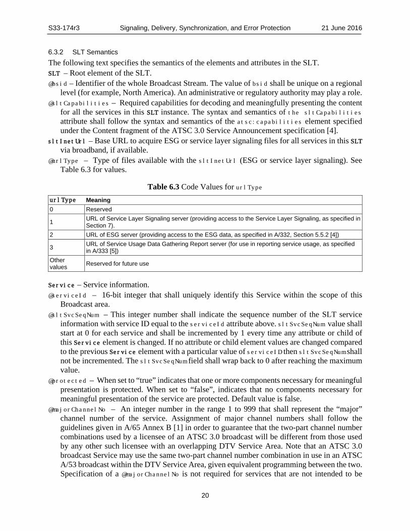
@urlType – Type of files available with the sltInetUrl (ESG or service layer signaling). See Table 6.3 for values.
Table 6.3 Code Values for urlType urlType Meaning 0 Reserved
1 URL of Service Layer Signaling server (providing access to the Service Layer Signaling, as specified in Section 7).
2 URL of ESG server (providing access to the ESG data, as specified in A/332, Section 5.5.2 [4])
3 URL of Service Usage Data Gathering Report server (for use in reporting service usage, as specified in A/333 [5])
Other values Reserved for future use
Service – Service information. @serviceId – 16-bit integer that shall uniquely identify this Service within the scope of this
Broadcast area. @sltSvcSeqNum – This integer number shall indicate the sequence number of the SLT service
information with service ID equal to the serviceId attribute above. sltSvcSeqNum value shall start at 0 for each service and shall be incremented by 1 every time any attribute or child of this Service element is changed. If no attribute or child element values are changed compared to the previous Service element with a particular value of serviceID then sltSvcSeqNum shall not be incremented. The sltSvcSeqNum field shall wrap back to 0 after reaching the maximum value.
@protected – When set to “true” indicates that one or more components necessary for meaningful presentation is protected. When set to “false”, indicates that no components necessary for meaningful presentation of the service are protected. Default value is false.
@majorChannelNo – An integer number in the range 1 to 999 that shall represent the “major” channel number of the service. Assignment of major channel numbers shall follow the guidelines given in A/65 Annex B [1] in order to guarantee that the two-part channel number combinations used by a licensee of an ATSC 3.0 broadcast will be different from those used by any other such licensee with an overlapping DTV Service Area. Note that an ATSC 3.0 broadcast Service may use the same two-part channel number combination in use in an ATSC A/53 broadcast within the DTV Service Area, given equivalent programming between the two. Specification of a @majorChannelNo is not required for services that are not intended to be
S33-174r3 Signaling, Delivery, Synchronization, and Error Protection 21 June 2016
21
selected directly by viewers, such as an ESG data delivery service or an EAS rich media delivery service.
@minorChannelNo – An integer number in the range 1 to 999 that shall represent the “minor” channel number of the service. This number is not required for services that are not intended to be selected directly by viewers, such as an ESG data delivery service or an EAS rich media delivery service.
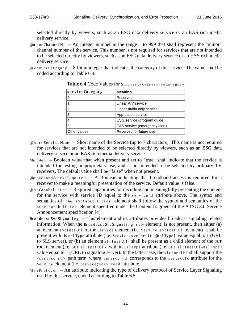
@serviceCategory – 8-bit in integer that indicates the category of this service. The value shall be coded according to Table 6.4.
Table 6.4 Code Values for SLT.Service@serviceCategory serviceCategory Meaning 0 Reserved 1 Linear A/V service 2 Linear audio only service 3 App-based service 4 ESG service (program guide) 5 EAS service (emergency alert) Other values Reserved for future use
@shortServiceName – Short name of the Service (up to 7 characters). This name is not required for services that are not intended to be selected directly by viewers, such as an ESG data delivery service or an EAS rich media delivery service.
@hidden – Boolean value that when present and set to “true” shall indicate that the service is intended for testing or proprietary use, and is not intended to be selected by ordinary TV receivers. The default value shall be “false” when not present.
@broadbandAccessRequired – A Boolean indicating that broadband access is required for a receiver to make a meaningful presentation of the service. Default value is false.
@svcCapabilities – Required capabilities for decoding and meaningfully presenting the content for the service with service ID equal to the serviceId attribute above. The syntax and semantics of the svcCapabilities element shall follow the syntax and semantics of the atsc:capabilities element specified under the Content fragment of the ATSC 3.0 Service Announcement specification [4].
BroadcastSvcSignaling – This element and its attributes provides broadcast signaling related information. When the BroadcastSvcSignaling sub-element is not present, then either (a) an element svcInetUrl of the Service element (i.e. Service.svcInetUrl element) shall be present with its urlType attribute (i.e. Service.svcInetUrl@urlType) value equal to 1 (URL to SLS server), or (b) an element sltInetUrl shall be present as a child element of the SLT root element (i.e. SLT.sltInetUrl) with its urlType attribute (i.e. SLT.sltInetUrl@urlType) value equal to 1 (URL to signaling server). In the latter case, the sltInetUrl shall support the <service_id> path term where service_id corresponds to the serviceId attribute for the Service element (i.e. Service@serviceId attribute).
@slsProtocol – An attribute indicating the type of delivery protocol of Service Layer Signaling used by this service, coded according to Table 6.5.

S33-174r3 Signaling, Delivery, Synchronization, and Error Protection 21 June 2016
22
Table 6.5 Code Values for SLT.Service.BroadcastSvcSignaling@slsProtocol slsProtocol Meaning 0 Reserved 1 ROUTE 2 MMTP other values Reserved for future use
@slsMajorProtocolVersion – Major version number of the protocol used to deliver the Service Layer Signaling for this service. Default value is 1.
@slsMinorProtocolVersion – Minor version number of the protocol used to deliver the Service Layer Signaling for this service. Default value is 0.
@slsPlpId - Integer number indicating the PLP ID of the physical layer pipe carrying the SLS for this service. PLP ID shall be as specified in A/322 [3].
@slsDestinationIpAddress – A string containing the dotted-IPv4 destination address of the packets carrying SLS data for this service.
@slsDestinationUdpPort – Port number of the packets carrying SLS data for this service. @slsSourceIpAddress – A string containing the dotted-IPv4 source address of the packets
carrying SLS data for this service. svcInetUrl– Base URL to access ESG or service layer signaling files for this service via
broadband, if available. @urlType – Type of files available with svcInetUrl. See Table 6.3 for values.
6.4 System Time Fragment System time is delivered in the ATSC PHY layer as a 32-bit count of the number of seconds and a 10-bit fraction of a second (in units of milliseconds) since January 1, 1970 00:00:00, International Atomic Time (TAI), which is the Precision Time Protocol (PTP) epoch as defined in IEEE 1588 [42]. Further time-related information is signaled in the XML SystemTime element delivered in LLS.
System Time shall be represented as an XML document containing a SystemTime root element that conforms to the definitions in the XML schema that has namespace:
http://www.atsc.org/XMLSchemas/ATSC3/Delivery/SYSTIME/1.0/
The definition of this schema is in a schema file accompanying this standard, as described in Section 3.6 above.
An LLS packet including SystemTime shall be included no more frequently than once per second and no less often than once every five seconds.
While the indicated XML schema specifies the normative syntax of the SystemTime element, informative Table 6.6 below describes the structure of the SystemTime element in a more illustrative way. The specifications following the table give the normative semantics of the elements and attributes.

S33-174r3 Signaling, Delivery, Synchronization, and Error Protection 21 June 2016
23
Table 6.6 SystemTime Element Structure Element or Attribute Name Use Data Type Description SystemTime 1
@currentUtcOffset 1 unsignedByte The current offset in whole seconds between TAI and UTC.
@ptpPrepend 0..1 unsignedShort Signals the upper 16 bits of the 48-bit count of PTP seconds.
@leap59 0..1 boolean Indicates a pending 59-second leap second event @leap61 0..1 boolean Indicates a pending 61-second leap second event @utcLocalOffset 1 duration Indicates the offset between the local time zone of the
originating broadcast station, and UTC. @dsStatus 0..1 boolean Indicates that Daylight Saving Time is in effect @dsDayOfMonth 0..1 unsignedByte
(range 1..31) Indicates the local day of the month on which the transition into or out of daylight saving time is to occur.
@dsHour 0..1 unsignedByte (range 0..24)
Indicates the local hour at which the transition into or out of daylight saving time is to occur (0–24).
SystemTime – Root element. @currentUtcOffset – This unsigned integer shall indicate the current offset in whole seconds
between TAI and UTC. Required. @ptpPrepend – This unsigned integer shall indicate, when present, the upper 16 bits of the 48-bit
count of PTP seconds. When not present, the value shall be understood to be zero. @leap59 – When present and set to “true”, shall indicate that the last minute of the current UTC
day contains 59 seconds. Default value is “false” @leap61 – When present and set to “true”, shall indicate that the last minute of the current UTC
day contains 61seconds. Default value is “false”. @utcLocalOffset – This attribute shall indicate the offset between UTC and the time zone of the
originating broadcast station. As a receiver may be located in a time zone adjacent to that of the broadcast transmitter, this offset is not directly usable to establish the time zone local to a given receiver. The @utcLocalOffset may be used to convert the value given in @dshour to the time of day local to the receiver. Example: for a broadcaster whose transmitter is located in the U.S. West Coast, when Daylight Saving is not in effect, @utcLocalOffset = "-P8H". For a broadcaster in Venezuela, @utcLocalOffset = "-P4H30M".
@dsStatus – When set to “true”, shall indicate that Daylight Saving Time is in effect in effect at the transmitter location. When set to “false”, shall indicate that Daylight Saving Time is not in effect in effect at the transmitter location. Shall be included whenever Daylight Saving Time is in effect in effect at the transmitter location. Default value when not present shall be “false”.
@dsDayOfMonth – This unsigned integer value in the range 1 to 31 shall indicate, when present, that a transition into or out of daylight saving time is to occur during the present month, and the local day of the month on which it to occur. @dsDayOfMonth shall be included whenever there will be a Daylight Saving Time transition during the current month. @dsDayOfMonth shall be omitted whenever there will not be a Daylight Saving Time transition during the current month.
@dsHour – Shall indicate the hour at which the transition into or out of daylight saving time is to occur (0–24), in the time zone of the originating broadcast station. Such transitions usually occur at 2 a.m. in the U.S. @dsHour shall be included whenever @dsDayOfMonth is present and shall not be included whenever @dsDayOfMonth is not present.
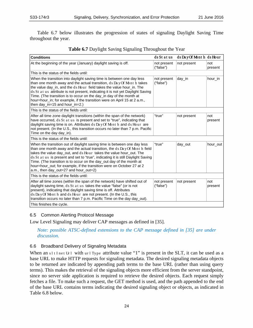
S33-174r3 Signaling, Delivery, Synchronization, and Error Protection 21 June 2016
24
Table 6.7 below illustrates the progression of states of signaling Daylight Saving Time throughout the year.
Table 6.7 Daylight Saving Signaling Throughout the Year Conditions dsStatus dsDayOfMonth dsHour
At the beginning of the year (January) daylight saving is off. not present (“false”)
not present not present
This is the status of the fields until: When the transition into daylight saving time is between one day less than one month away and the actual transition, dsDayOfMonth takes the value day_in, and the dsHour field takes the value hour_in. The dsStatus attribute is not present, indicating it is not yet Daylight Saving Time. (The transition is to occur on the day_in day of the month at hour=hour_in; for example, if the transition were on April 15 at 2 a.m., then day_in=15 and hour_in=2.)
not present (“false”)
day_in hour_in
This is the status of the fields until: After all time zone daylight transitions (within the span of the network) have occurred, dsStatus is present and set to “true”, indicating that daylight saving time is on. Attributes dsDayOfMonth and dsHour are not present. (In the U.S., this transition occurs no later than 7 p.m. Pacific Time on the day day_in).
“true” not present not present
This is the status of the fields until: When the transition out of daylight saving time is between one day less than one month away and the actual transition, the dsDayOfMonth field takes the value day_out, and dsHour takes the value hour_out. The dsStatus is present and set to “true”, indicating it is still Daylight Saving Time. (The transition is to occur on the day_out day of the month at hour=hour_out; for example, if the transition were on October 27 at 2 a.m., then day_out=27 and hour_out=2)
“true” day_out hour_out
This is the status of the fields until: After all time zones (within the span of the network) have shifted out of daylight saving time, dsStatus takes the value “false” (or is not present), indicating that daylight saving time is off. Attributes dsDayOfMonth and dsHour are not present. (In the U.S., this transition occurs no later than 7 p.m. Pacific Time on the day day_out).
not present (“false”)
not present not present
This finishes the cycle.
6.5 Common Alerting Protocol Message Low Level Signaling may deliver CAP messages as defined in [35].
Note: possible ATSC-defined extensions to the CAP message defined in [35] are under discussion.
6.6 Broadband Delivery of Signaling Metadata When an sltInetUrl with urlType attribute value “1” is present in the SLT, it can be used as a base URL to make HTTP requests for signaling metadata. The desired signaling metadata objects to be returned are indicated by appending path terms to the base URL (rather than using query terms). This makes the retrieval of the signaling objects more efficient from the server standpoint, since no server side application is required to retrieve the desired objects. Each request simply fetches a file. To make such a request, the GET method is used, and the path appended to the end of the base URL contains terms indicating the desired signaling object or objects, as indicated in Table 6.8 below.

S33-174r3 Signaling, Delivery, Synchronization, and Error Protection 21 June 2016
25
Table 6.8 Path Terms, in Order of Appearance in Path Terms Meaning <service_id> Identifies desired service
normal|diff|template Identifies desired mode of files
current|next Identifies desired current/next version
ALL|RD|USBD|STSID|MPD|MMT|MPT|PAT|MPIT|CRIT|DCIT|AST|EMT|AEI Identifies desired type of object(s)
When an sltInetUrl with urlType attribute "1" base URL appears (at the SLT level), the service_id term is used to indicate the service to which the requested signaling metadata objects apply. If the service_id term is not present, then the signaling metadata objects for all services in the section are requested.
The normal/diff/template term indicates whether the normal form of the metadata object(s), the diff form of the metadata object(s), or the template form of the metadata object(s) is requested. If the normal form is desired, the normal term shall be omitted.
The current/next term indicates whether the current version of the metadata object(s) or the next version of the metadata object(s) after the current version is requested. If the current version is desired, then the current term shall be omitted.
The fourth term is used to indicate which types of metadata object(s) are desired. The supported types are listed in Table 6.9 below, with their descriptions.
Table 6.9 Metadata Object Types Name Values ALL All metadata objects for requested service(s) RD All ROUTE/DASH metadata objects for requested service(s) APD APD for requested service(s) MMT All MMT metadata objects for requested service(s) USBD USBD for requested service(s) STSID S-TSID for requested service(s) MPD DASH MPD for requested service(s) PAT MMT Package Access Table for requested service(s) MPT MMT Package Table for requested service(s) MPIT MMT Media Presentation Information Table for requested service(s) CRIT MMT Clock Relation Information Table for requested service(s) DCIT MMT Device Capabilities Information Table for requested service(s) AST Application Signaling Table for requested service(s) EMT ROUTE/DASH Event Messages Table for requested service(s) AEI MMT Application Event Information for requested service(s)
Some examples of the URL for an HTTP request for signaling metadata objects would be: <sltInetUrl urlType="1">/0x2107/RD – returns the current, normal version of all
ROUTE/DASH signaling objects for service with service_id 0x2107 <sltInetUrl urlType="1">/0x2103/next/MPD – returns the next, normal version of the
MPD for service with service_id 0x2103
S33-174r3 Signaling, Delivery, Synchronization, and Error Protection 21 June 2016
26
<sltInetUrl urlType="1">/0x2104/template/AST – returns the current, template version of the AST for service with service_id 0x2104
<sltInetUrl urlType="1">/0x2110/template/ALL – returns the current, template versions of all the metadata objects as denoted in Table 6.9, for the service with service_id 0x2110
When an svcInetUrl with urlType attribute "1" appears (at the service layer), then the same paths can be appended to the end of it, with the same semantics, except that no service term shall appear, since it is not needed to designate the desired service.
The response body for those HTTP requests shall include an MBMS metadata envelope per Section 11.1.3 of MBMS [9] containing an item element for each signaling object included in the response. Either zero or one of the signaling objects may be embedded in its item element, as specified in the MBMS standard [40]. Any signaling objects that are not embedded shall be referenced in their item elements, and they shall be packaged together with the metadata envelope in a multi-part MIME message, in the order in which they are referenced. The validFrom and validUntil attributes of the item elements should be present, to indicate the interval of validity of each signaling object.
The item element of the MBMS metadata envelope shall be extended by the addition of the following attribute, defined in an ATSC namespace:
<xs:attribute name="nextUrl" type="xs:anyURI" use="optional"/>
When present, the URL given by this attribute shall be the URL of the next scheduled update to the signaling object described in the item element.
Thus, when the validUntil time approaches for a signaling object that was acquired via broadband, the device can acquire the next scheduled update to the signaling object by making an HTTP GET request with the URL given by the nextURL attribute in the item element that was used to represent the signaling object in the metadata envelope.
If an unscheduled update is made to a signaling object, a dynamic event will be issued announcing the update, as specified in the ATSC 3.0 Application Signaling and Triggers Standard [39]. A device can then acquire the updated signaling object, using the URL in the data attribute of the dynamic event.
When an sltInetUrl with urlType attribute "2" is present, the URL given by this element can be used to retrieve ESG data via broadband for all services in the SLT. When a svcInetUrl with urlType attribute "2" is present, the URL given by this attribute can be used to retrieve ESG data via broadband for the service with the same serviceId as the service element in which the svcInetUrl appears. In both cases the URL is used for queries as specified in the ATSC 3.0 Service Announcement Standard [4].
7. SERVICE LAYER SIGNALING For ROUTE/DASH, the SLS for each service describes characteristics of the service, such as a list of its components and where to acquire them, and the receiver capabilities required to make a meaningful presentation of the service, and the availability and associated rules regarding access to file repair services by receivers. In the ROUTE/DASH system, the SLS includes the User Service Bundle Description (USBD), the S-TSID, the Associated Procedure Description (APD) and the DASH Media Presentation Description (MPD). The USBD and APD are based on the identically-named (i.e. User Service Bundle Description and Associated Procedure Description)

S33-174r3 Signaling, Delivery, Synchronization, and Error Protection 21 June 2016
27
service description metadata fragments as defined in MBMS [9], with extensions that support ATSC 3.0 requirements. Table 7.1 shows the elements and attributes of the ROUTE/DASH USBD that would be used in practice for ATSC 3.0 service delivery.
For MMTP, the SLS for each service describes characteristics of the service, such as a list of its components and where to acquire them, and the receiver capabilities required to make a meaningful presentation of the service. In the MMTP system, the SLS includes the USBD fragment and the MMT Package (MP) table. For hybrid delivery, the MMT SLS can further include the MPD for broadband components. Table 7.5 shows the elements and attributes of the MMTP USBD that would be used in practice for ATSC 3.0 service delivery.
The Service Signaling focuses on basic attributes of the service itself, especially those attributes needed to acquire the service. Properties of the service and programming that are intended for viewers appear as Service Announcement, or ESG data. Carriage of the ESG is specified in the ATSC 3.0 Service Announcement specification [4].
Having separate Service Signaling for each service permits a receiver to acquire the appropriate SLS for a service of interest without the need to parse the entire SLS carried within a Broadcast Stream.
For optional broadband delivery of Service Signaling, the SLT can include HTTP URLs where the Service Signaling files can be obtained. (See Section 6.3 above.)
Figure 7.1 provides an example of the use of the LLS to bootstrap SLS acquisition, and subsequently, the use of the SLS to acquire service components delivered on either ROUTE sessions or MMTP sessions. The figure illustrates the following signaling sequences. ATSC 3.0 receiver starts acquiring the SLT described in Section 6.3. Each service identified by service_id delivered over ROUTE sessions provides SLS bootstrapping information: PLPID(#1), source IP address (sIP1), destination IP address (dIP1), and destination port number (dPort1). Each service identified by service_id delivered over MMTP sessions provides SLS bootstrapping information: PLPID(#2), destination IP address (dIP2), and destination port number (dPort2).
For streaming services delivery using ROUTE, the receiver can acquire SLS fragments carried over the IP/UDP/LCT channel and PLP as indicated in the SLT; whereas for streaming services delivery using MMTP, the receiver can acquire SLS fragments carried over an MMTP session and PLP. For service delivery using ROUTE, these fragments include USBD/USD fragments, S-TSID fragments, APD fragments, and MPD fragments. They are relevant to one service. USBD/USD fragments describe service layer properties and provide URI references to S-TSID fragments and URI references to MPD fragments. For service delivery using MMTP, the USBD references the MMT Signaling’s MPT Message, the MP Table of which provides identification of Package ID and location information for assets belonging to the service.
The S-TSID fragment provides component acquisition information associated with one service and mapping between DASH Representations found in the MPD and in the TSI corresponding to the component of the service. The S-TSID can provide component acquisition information in the form of a TSI and the associated DASH Representation identifier, and PLPID carrying DASH Segments associated with the DASH Representation. By the PLPID and TSI values, the receiver collects the audio/video components from the service and begins buffering DASH Media Segments then applies the appropriate decoding processes.
The APD fragment provides information regarding the HTTP file repair procedure, which may be initiated by the receiver to a file repair server, after broadcast delivery of the delivery object of interest has ended, but the entire object was not successfully received. The use of the file repair

S33-174r3 Signaling, Delivery, Synchronization, and Error Protection 21 June 2016
28
procedure is nominally used to support broadcast delivery of NRT content, e.g., application-related files that belong to an app-based enhancement, or data services such as the ESG or EAS content.
For USBD listing service components delivered on MMTP sessions, as illustrated by “Service #2” in Figure 7.1, the receiver also acquires an MPT message with matching MMT_package_id to complete the SLS. An MPT message provides the full list of service components comprising a service and the acquisition information for each component. Component acquisition information includes MMTP session information and the packet_id within that session.
Figure 7.1 Example use of service signaling for bootstrapping and service
discovery.
Annex B provides an example implementation of the ATSC 3.0 hierarchical signaling architecture featuring two separate S-TSID fragments, each of which provides the access information for the LCT channels carrying the contents of an individual ATSC 3.0 service.
7.1 ROUTE/DASH Service Layer Signaling Service Layer Signaling provides detailed technical information to the ATSC 3.0 receiver to enable the discovery and access of ATSC 3.0 user services and their content components. It comprises a set of XML-encoded metadata fragments carried over a dedicated LCT channel. That LCT channel can be acquired using the bootstrap information contained in the SLT as described in Section 6.3. The SLS is defined on a per-service level, and it describes the characteristics and access information of the service, such as a list of its content components and how to acquire them, and the receiver capabilities required to make a meaningful presentation of the service, and the means to recover partially-received objects.. In the ROUTE/DASH system, for linear services delivery,
Service #1 Service Layer Signaling
SLTBSID
service #2 service_id (0x1002) short_name (XYZ) SLS_protocol_type(MMTP) ...
broadcast_SLS_signaling sIP(sIP2) dIP(dIP2) dPort (dPort2) PLP_ID (#2)
USBD/USD
service #1 service_id (0x1001) short_name (ABC) SLS_protocol_type(ROUTE) ... broadcast_SLS_signaling sIP(sIP1) dIP(dIP1) dPort (dPort1) PLP_ID (#1)
S-TSID MPD
MPD period
UserServiceDescription
@atscServiceId (0x1001) service attributes ...
AdaptationSet segmentURL(video/Seg#1) representation (Rv)
AdaptationSet segmentURL(audio/Seg#1) representation (Ra)
RS
LCT Channel ... @tsi-v SrcFlow ContentInfo(Rv)
LCT Channel ... @tsi-a SrcFlow ContentInfo(Ra)
Physical Layer Frame(BSID)
PLP(#1)
SLT
sIP1dIP1
dPort1 LCT(tsi-v) Video Segments
LCT(tsi-a) Audio Segments
LCT (tsi=0) Service Signaling
PLP(#2)packet_id-v Video MPUs
packet_id-a Audio MPUs
sIP2dIP2
dPort2
packet_id-s Service Signaling
Service #2 Service Layer Signaling
USBD/USD
UserServiceDescription
@atscServiceId (0x1002) service attributes …
atsc:mpuComponent
MMT signaling Message
UDP/IPPLP(#0)
APD
postFileRepair
@offsetTime @randomTimePeriod

S33-174r3 Signaling, Delivery, Synchronization, and Error Protection 21 June 2016
29
the SLS consists of the following metadata fragments: USBD, S-TSID and the DASH MPD. The SLS fragments shall be delivered on a dedicated LCT transport channel with TSI = 0.
The data model of the SLS fragments applicable to linear services, shown using UML convention, is shown in Figure 7.2.
Figure 7.2 Service Layer Signaling data model for Linear Services.
ROUTE/DASH Service Layer Signaling comprises the User Service Bundle Description (USBD) and Service-based Transport Session Instance Description (S-TSID), Associated Procedure Description (APD), and Media Presentation Description (MPD) metadata fragments. These service signaling fragments are applicable to linear services, and with the possible exception of the MPD fragment, also to application-based services. The USBD fragment contains service identification, device capabilities information, references to other SLS fragments required to access the service and constituent media components, and metadata to enable the receiver to determine the transport mode (broadcast and/or broadband) of service components. The S-TSID fragment, referenced by the USBD, provides transport session descriptions for the one or more ROUTE sessions in which the media content components of an ATSC 3.0 service are delivered, and descriptions of the delivery objects carried in those LCT channels. In addition, each of the deliveryMethod elements in the USBD may reference an instance of the APD fragment which, in conjunction with EFDT parameters as defined in Annex A, Section A.3.3.2, provide metadata for supporting HTTP file repair. The APD fragment, if present, shall be associated with either a source flow or a repair flow which carries the delivery object of interest. The USBD, S-TSID and APD are further detailed in Sections 7.1.3 and 7.1.4 and 7.1.7.
Streaming Content Signaling The streaming content signaling component of the SLS corresponds to the MPD fragment. The MPD is typically associated with linear services for the delivery of DASH Segments as streaming content. The MPD provides the resource identifiers for individual media components of the linear/streaming service in the form of Segment URLs, and the context of the identified resources within the Media Presentation. It is further described in Section 7.2.2.
1 includes 1
1
1userServiceDescription
MediaPresentationDescription
UserServiceBundle
Description
Service TransportSession Instance
Description
1
1references
1..N
AssociatedProcedureDescription
deliveryMethod
1..N
0.1
references
SrcFlow
1
0..Nincludes
10..1
includes
fullMPDUri11
RepairFlow
1
0..N
includes
references
0..1 1

S33-174r3 Signaling, Delivery, Synchronization, and Error Protection 21 June 2016
30
App-based Enhancement Signaling App-based enhancement signaling pertains to the delivery of app-based enhancement components, such as an application logic file, locally-cached media files, a network content item, or a notification stream. Note that an application can also retrieve locally-cached data over a broadband connection when available.
[TBD]Details about app-based enhancement signaling are specified in the Application Signaling & Trigger Specification, A/337 [39]. User Service Description
The top level or entry point SLS fragment is the USBD fragment. The USBD fragment for ATSC 3.0 is modeled on the USBD fragment as defined by MBMS [9], with the following extension:
• Child attributes serviceId, serviceStatus, fullMPDUri, sTSIDUri, aPDUri and capabilityCode under the element userServiceDescription;
The following extensions defined in MBMS [9] are included: • Child element broadcastAppService and its child element basePattern under the
element deliveryMethod; • Child element unicastcastAppService and its child element basePattern under the
element deliveryMethod. The bundleDescription shall be represented as an XML document containing a
bundleDescription root element that conforms to the definitions in the XML schema that has namespace:
http://www.atsc.org/XMLSchemas/ATSC3/Delivery/ROUTEUSD/1.0/
The definitions of these schemas are in schema files accompanying this standard, as described in Section 3.6 above.
While the XML schemas identified above specify the normative syntax of the elements specified in this ATSC 3.0 standard, informative Table 7.1 below describes the structure of the bundleDescription element of MBMS [9], including the ATSC extensions, in a more illustrative way. A large number of the attributes and elements in the MBMS USBD fragment are optional and not relevant to ATSC 3.0. Table 7.1 shows the elements and attributes that would be used in practice for ATSC 3.0 service delivery.

S33-174r3 Signaling, Delivery, Synchronization, and Error Protection 21 June 2016
31
Table 7.1 Semantics of the User Service Bundle Description Fragment for ROUTE/DASH
7.1.3.1 User Service Description for ROUTE – Semantics The following text specifies the semantics of the elements and attributes in the USBD fragment. bundleDescription – Root element of the User Service Bundle Description. UserServiceDescription – A complex element whose subordinate elements and attributes
contain additional information for a single ATSC 3.0 Service. @globalServiceID – The globally unique URI value that shall represent the identity of the ATSC
3.0 service named in the parent USBD fragment. This attribute provides the linkage to, and its
Element or Attribute Name Use Data Type Description
bundleDescription Root element of the User Service Bundle
Description. userServiceDescription A single instance of an ATSC 3.0 Service. @globalServiceID 0..1 anyURI A globally unique URI that identifies the ATSC 3.0
Service. @serviceId 1 unsignedShort Reference to corresponding service entry in the
(SLT). @serviceStatus 0..1 boolean Specify the status of this service as active or
inactive. @fullMPDUri 1 anyURI Reference to an MPD fragment that contains
descriptions for content components of the ATSC 3.0 Service delivered over broadcast and/or broadband.
@sTSIDUri 1 anyURI Reference to the S-TSID fragment which provides access related parameters for the Transport sessions carrying contents of this ATSC 3.0 Service.
name 0..N string Name of the ATSC 3.0 service. @lang 1 language Language of the ATSC 3.0 service name. serviceLanguage 0..N language Available languages of the ATSC 3.0 service. deliveryMethod 1..N Container of transport-related information pertaining
to the contents of the service over broadcast and (optionally) broadband modes of access.
@apdUri 0..1 anyURI Reference to the APD fragment which contains file repair related information.
broadcastAppService 0..N A DASH Representation delivered over broadcast containing the corresponding media component(s) belonging to the ATSC 3.0 Service.
basePattern 1..N string A character pattern for use by the ATSC receiver to match against any portion of the Segment URL used by the DASH client to request Media Segments of a parent Representation.
unicastAppService 0..N A DASH Representation delivered over broadband containing the constituent media content component(s) belonging to the ATSC 3.0 Service.
basePattern 1..N string A character pattern for use by the ATSC receiver to match against any portion of the Segment URL used by the DASH client to request Media Segments of a parent Representation.

S33-174r3 Signaling, Delivery, Synchronization, and Error Protection 21 June 2016
32
value shall be identical to that of the Service@globalServiceID attribute in the ESG [4]. This attribute shall be present for the Linear A/V, Linear audio only, and App-based services.
@serviceId – A 16-bit integer value that shall identify the ATSC 3.0 service named in the parent USBD fragment and whose uniqueness pertains to the scope of this Broadcast area. Its value shall be identical to that of the SLT.Service.serviceId attribute in the SLT which references the LCT channel carrying the USBD fragment for this service.
@serviceStatus – A Boolean attribute which shall convey the current status of this service as being active or inactive. When set to “1” or “true”, it is an indication that the service is active, and when set to “0” or “false”, it is an indication that the service is inactive. Its default value shall be “1” or “true”.
@fullMPDUri – A URL whose value shall represent the resource location of the MPD fragment that contains descriptions for content components of this ATSC 3.0 service which is delivered over broadcast and/or broadband. This attribute shall be present for the Linear A/V and Linear audio only service. In addition, this attribute is not applicable to and therefore shall be absent for the ESG and EAS services.
@sTSIDUri – A URL whose value shall represent the resource location of the S-TSID fragment which contains transport/access related parameters for the LCT channels allocated to carry the content components of this ATSC 3.0 service.
name – This element shall contain the name of this ATSC 3.0 service as given by one or more languages as defined by its lang attribute.
@lang – This attribute shall indicate the language for the name of this ATSC 3.0 service, and which shall be represented by formal natural language identifiers as defined by BCP 47 [24].
serviceLanguage – This element shall indicate the language for this ATSC 3.0 service, and which shall be represented by formal natural language identifiers as defined by BCP 47 [24].
deliveryMethod – A complex element whose subordinate elements and attributes contain transport related information pertaining to the contents of this ATSC 3.0 service. This element shall contain information on the delivery mode (broadcast, broadband, or via both paths) for each of those content components. This element is not applicable to and therefore shall be absent for the ESG and EAS services.
At least one of broadcastAppService or unicastAppService child elements shall be present under each deliveryMethod element.
@apdUri – A URL whose value shall represent the resource location of the APD fragment which contains file repair related information.
broadcastAppService – This element shall be an indication that the content item of this ATSC 3.0 service as requested by an application in the receiver is delivered over broadcast, i.e. via the ROUTE protocol. The presence of this element may be used alone, or in conjunction with its child element basePattern, to determine whether the delivery path for that content is broadcast.
basePattern (under broadcastAppService) – A string value, typically in the form of a base URI, which shall be used for matching against the resource URL provided by the application for making a request of a content component of the ATSC 3.0 service. The occurrence of a full match of a broadcastAppService.basePattern value to a contiguous portion of the request URL shall be an indication to the receiver that the requested content is delivered by broadcast.
unicastAppService – This element shall be an indication that the content item of this ATSC 3.0 service as requested by an application in the receiver is delivered over broadband, via the HTTP

S33-174r3 Signaling, Delivery, Synchronization, and Error Protection 21 June 2016
33
protocol. The presence of this element may be used alone, or in conjunction with its child element basePattern, to determine whether the delivery path for that content is broadband.
basePattern (under unicastAppService ) – A string value, typically in the form of a base URI, which shall be used for matching against the resource URL provided by the application for making a request of a content component of the ATSC 3.0 service. The occurrence of a full match of a unicastAppService.basePattern value to a contiguous portion of the request URL shall be an indication to the receiver that the requested content is delivered by broadband. Service-based Transport Session Instance Description (S-TSID)
The S-TSID is the SLS metadata fragment that contains the overall transport session description information for the zero or more ROUTE sessions and constituent LCT channels in which the media content components of an ATSC 3.0 service are delivered. The S-TSID also includes file metadata for the delivery object or object flow carried in the LCT channels of the service, as well as additional information on the payload formats and content components carried in those LCT channels.
Each instance of the S-TSID fragment is referenced in the USBD fragment by the @sTSIDUri attribute of the userServiceDescription element. See Annex A.3 and A.4 for additional information.
Table 7.2 contains the semantics of the S-TSID fragment. Note that the SrcFlow and RepairFlow elements of the S-TSID are defined in Annex A (see Sections A.1.2, A.1.3, A.3 and A.4).
The S-TSID shall be represented as an XML document containing a S-TSID root element that conforms to the definitions in the XML schema that has namespace:
http://www.atsc.org/XMLSchemas/ATSC3/Delivery/ROUTESLS/1.0/
The definition of this schema is in a schema file accompanying this standard, as described in Section 3.6 above.
While the indicated XML schema specifies the normative syntax of the S-TSID element, informative Table 7.2 below describes the structure of the S-TSID element in a more illustrative way. See Annex A.3 and A.4 for additional information.

S33-174r3 Signaling, Delivery, Synchronization, and Error Protection 21 June 2016
34
Table 7.2 Semantics of the Service-based Transport Session Instance Description Fragment
Element and Attribute Names Use Data Type Description S-TSID Service Transport Session Instance Description @bsid 0..1 unsignedShort Identifier of the Broadcast Stream within which the
content component(s) of the broadcast service are carried.
@serviceId 0..1 unsignedShort Reference to corresponding service element in the USBD fragment.
RS 1..N ROUTE session @sIpAddr 0..1 string Source IP address of this ROUTE session;
mandatory for ROUTE session other than session carrying SLS (session signaled in SLT); defaults to session carrying SLS.
@dIpAddr 0..1 string Destination IP address of this ROUTE session; mandatory for ROUTE session other than session carrying SLS (session signaled in SLT); defaults to session carrying SLS.
@dport 0..1 unsignedShort Destination port of this ROUTE session; mandatory for ROUTE session other than session carrying SLS (session signaled in SLT); defaults to session carrying SLS.
LS 1..N LCT channel @tsi 1 unsignedInt TSI value @bw 0..1 unsignedInt Maximum bandwidth @startTime 0..1 dateTime Start time @endTime 0..1 dateTime End time SrcFlow 0..1 srcFlowType Information about the Source Flow RepairFlow 0..1 rprFlowType Information about the Repair Flow
The following text specifies the semantics of the portion of elements and attributes in the S-TSID fragment represented in Table 7.2. @bsId – A 16-bit unsigned integer value that shall identify the Broadcast Stream within which the
content component(s) of this ATSC 3.0 service are carried. When this attribute is absent, the default Broadcast Stream shall be the one whose PLPs carry SLS fragments for this ATSC 3.0 service. The value of this attribute shall be identical to that of the @bsid in the SLT.
S-TSID – Root element of the Service-based Transport Session Instance Description. @serviceId – A 16-bit unsigned integer value that shall identify the ATSC 3.0 service named in
the USBD fragment which references this S-TSID fragment. Its value and semantics shall be identical to that of the serviceId attribute in the USBD fragment.
RS – A complex element whose subordinate elements and attributes contain information about the one or more ROUTE sessions in which the content components of this ATSC 3.0 service are carried.
@sIpAddr – A dotted-IPv4 source IP address whose value shall represent the source IP address for this ROUTE session. When this attribute is absent, the default value shall be the source IP address of the ROUTE session whose LCT channel carries the SLS fragments for this service. This attribute shall be present if this ROUTE session, whose LCT channel carries content component(s) of this service, is not the primary ROUTE session associated with this service.
S33-174r3 Signaling, Delivery, Synchronization, and Error Protection 21 June 2016
35
@dIpAddr – A dotted-IPv4 destination IP address whose value shall represent the destination IP addess for this ROUTE session. When this attribute is absent, the default value shall be the destination IP address of the ROUTE session whose LCT channel carries the SLS fragments for this service. This attribute shall be present if this ROUTE session, whose LCT channel carries content component(s) of this service, is not the primary ROUTE session associated with this service.
@dport – A destination port number whose value shall be associated with the dotted-IPv4 destination IP address for this ROUTE session. When this attribute is absent, the default value shall be the destination port number of the ROUTE session whose LCT channel carries the SLS fragments for this service. This attribute shall be present if this ROUTE session, whose LCT channel carries content component(s) of this service, is not the primary ROUTE session associated with this service.
LS – A complex element whose subordinate elements and attributes contain information about each of the one or more LCT channels that carry content component(s) of the ATSC 3.0 service to which the ROUTE session(s) identified in this S-TSID are associated.
@tsi – A 32-bit unsigned integer which shall represent the value of the Transport Session Identifier (TSI) for this LCT channel and whose uniqueness shall be scoped by its parent ROUTE session.
@bw – A 32-bit unsigned integer which when present, shall represent the maximum bit-rate required by this LCT channel. It shall be specified by using the Application Specific (AS) bandwidth modifier, at the media level, in RFC 4566 [17]. The AS bandwidth for an LCT channel of the parent ROUTE session shall be the largest value among the sum of the sizes of all packets transmitted during any one second long period of the session, expressed in kilobits. The size of the packet shall be the complete packet, i.e. comprising IP, UDP and ROUTE headers, and the data payload.
@startTime – This attribute shall represent the start time of this LCT channel, defined in accordance to the time description, i.e. “t=” line in RFC 4566 [17], and representing the “t=<start-time>” value, The only difference from RFC 4566 [17] is in the format of the session start time – i.e., instead of decimal representation of the NTP (Network Time Protocol) time value, in this specification, the session start time shall be represented by the “dateTime” XML datatype as defined in XSD Datatypes [37].
@endTime – This attribute shall represent the end time of this LCT channel, defined in accordance to the time description, i.e. “t=” line in RFC 4566 [17], and representing the “t=<end-time>” value, The only difference from RFC 4566 [17] is in the format of the session end time – i.e., instead of decimal representation of the NTP (Network Time Protocol) time value, in this specification, the session end time shall be represented by the “dateTime” XML datatype as defined in XSD Datatypes [37].
SrcFlow – A complex element whose subordinate elements and attributes contain information about each of the one or more Source Flows (as defined in Annex A, Section A.3), within its parent LCT channel.
RepairFlow – A complex element whose subordinate elements and attributes contain information about each of the one or Repair Flows (as defined in Annex A, Section A.4), within its parent LCT channel. Media Presentation Description (MPD)
The MPD is an SLS metadata fragment which contains a formalized description of the DASH-IF [8] profile of a DASH Media Presentation, corresponding to a linear service of a given duration

S33-174r3 Signaling, Delivery, Synchronization, and Error Protection 21 June 2016
36
defined by the broadcaster (for example a single TV program, or the set of contiguous linear TV programs over a period of time). The contents of the MPD provide the resource identifiers for Segments and the context for the identified resources within the Media Presentation. The data structure and semantics of the MPD fragment shall be according to the Media Presentation Description as defined by the DASH-IF [8] profile of MPEG DASH [47].
In the context of ATSC 3.0 services, one or more of the DASH Representations conveyed in the MPD are carried over broadcast. The MPD may describe additional Representations delivered over broadband, e.g. in the case of a hybrid service, or to support service continuity in handoff from broadcast to broadcast due to broadcast signal degradation (e.g. driving through a tunnel). 7.1.5.1 Delivery Path Signaling URLs in the MPD corresponding to items delivered in the broadcast stream shall be of the form
http://localhost/… .
URLs in the MPD corresponding to items delivered via the broadband path shall use http:// or https:// protocol identifier followed by a valid IP address or domain name. 7.1.5.2 Signaling for Staggercast Audio Representation Staggercast is a robustness feature that can be optionally added to audio components. It consists of delivering a redundant version of a main audio component, possibly coded with lower quality (e.g. lower bitrate, number of channels, etc.) and with a significant delay ahead of the audio with which it is associated.
Note: For live content, staggercast audio stream may be sent ahead of the main audio stream by, for instance, taking advantage of the internal delay of encoding a video GoP. "
Receivers that support Staggercast feature can switch to the Staggercast stream should main audio become unavailable. The delivery delay between Staggercast audio and main audio should be chosen high enough to provide robustness given the sufficient time diversity between both audios.
To explicitly signal that a Representation is only suitable for Staggercast, the MPD shall be constructed as follows:
• Include an Adaptation Set that that contains one and only one Staggercast audio Representation;
• Annotate the Adaptation Set with an EssentialProperty descriptor with SchemeIdUri set to "tag:atsc.org,2016:staggercast" and the @value attribute set to the value of the @id attribute of the Adaptation Set to which the Staggercast Representation belongs. The value may also be a white-space separated list of @id values. In this case the Staggercast Adaptation Set is associated with all Adaptation Sets with the indicated @id values.
• Each Staggercast Representation shall be time-aligned with the Representation in the main Adaptation Set.
If an Adaptation Set is annotated with an EssentialProperty descriptor with SchemeIdUri set to "tag:atsc.org,2016:staggercast" then the receiver is expected to not select such Representation for regular playout. If the receiver supports the Staggercast feature, it is expected to buffer both the main audio and the Staggercast audio in order to be able to switch to the Staggercast audio, should main audio become unavailable.
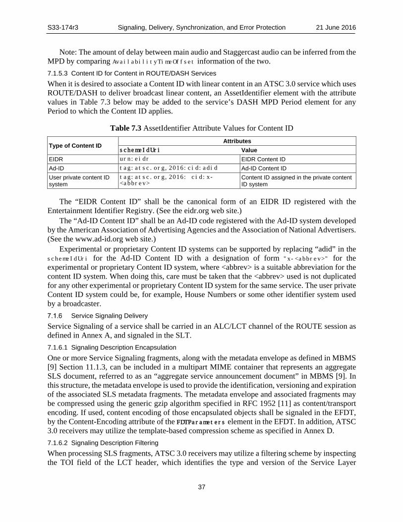
S33-174r3 Signaling, Delivery, Synchronization, and Error Protection 21 June 2016
37
Note: The amount of delay between main audio and Staggercast audio can be inferred from the MPD by comparing AvailabilityTimeOffset information of the two. 7.1.5.3 Content ID for Content in ROUTE/DASH Services When it is desired to associate a Content ID with linear content in an ATSC 3.0 service which uses ROUTE/DASH to deliver broadcast linear content, an AssetIdentifier element with the attribute values in Table 7.3 below may be added to the service’s DASH MPD Period element for any Period to which the Content ID applies.
Table 7.3 AssetIdentifier Attribute Values for Content ID
Type of Content ID Attributes
schemeIdUri Value EIDR urn:eidr EIDR Content ID Ad-ID tag:atsc.org,2016:cid:adid Ad-ID Content ID User private content ID system
tag:atsc.org,2016: cid:x-<abbrev>
Content ID assigned in the private content ID system
The “EIDR Content ID” shall be the canonical form of an EIDR ID registered with the Entertainment Identifier Registry. (See the eidr.org web site.)
The “Ad-ID Content ID” shall be an Ad-ID code registered with the Ad-ID system developed by the American Association of Advertising Agencies and the Association of National Advertisers. (See the www.ad-id.org web site.)
Experimental or proprietary Content ID systems can be supported by replacing “adid” in the schemeIdUri for the Ad-ID Content ID with a designation of form "x-<abbrev>" for the experimental or proprietary Content ID system, where <abbrev> is a suitable abbreviation for the content ID system. When doing this, care must be taken that the <abbrev> used is not duplicated for any other experimental or proprietary Content ID system for the same service. The user private Content ID system could be, for example, House Numbers or some other identifier system used by a broadcaster.
Service Signaling Delivery Service Signaling of a service shall be carried in an ALC/LCT channel of the ROUTE session as defined in Annex A, and signaled in the SLT. 7.1.6.1 Signaling Description Encapsulation One or more Service Signaling fragments, along with the metadata envelope as defined in MBMS [9] Section 11.1.3, can be included in a multipart MIME container that represents an aggregate SLS document, referred to as an “aggregate service announcement document” in MBMS [9]. In this structure, the metadata envelope is used to provide the identification, versioning and expiration of the associated SLS metadata fragments. The metadata envelope and associated fragments may be compressed using the generic gzip algorithm specified in RFC 1952 [11] as content/transport encoding. If used, content encoding of those encapsulated objects shall be signaled in the EFDT, by the Content-Encoding attribute of the FDTParameters element in the EFDT. In addition, ATSC 3.0 receivers may utilize the template-based compression scheme as specified in Annex D. 7.1.6.2 Signaling Description Filtering When processing SLS fragments, ATSC 3.0 receivers may utilize a filtering scheme by inspecting the TOI field of the LCT header, which identifies the type and version of the Service Layer

S33-174r3 Signaling, Delivery, Synchronization, and Error Protection 21 June 2016
38
Signaling fragment. The TOI field of the LCT header shall be constructed according to the rules specified in Annex C. This enables quick filtering for target LCT packets which carry Service Layer Signaling fragments of the desired type before recovering whole Service Layer Signaling fragment from those packets. See Annex C for a detailed example.
Associated Procedure Description (APD) The APD is an SLS metadata fragment containing information for use in conjunction with certain parameters in the EFDT element of the S-TSID fragment (as described in Section A.3.3.2.3) to govern the optional use by the receiver of the HTTP file repair functionality. The file repair procedure corresponds to an HTTP request/response transaction whereby a receiver, unable to acquire the entire object delivered by ROUTE, can request and obtain the missing data via broadband from a file repair server.
The APD fragment provides temporal information, under the postFileReception element, for the receiver, if it wishes to perform the file repair procedure to obtain missing data. The offsetTime child element of postFileReception represents the time interval in seconds that the receiver shall wait, after the end of transmission for the file of interest has occurred, before it can start the file repair procedure. The means by which the receiver could determine the end of file transmission, and the associated time window within which it is allowed to perform file repair, are described in Section 7.1.7.2. The randomTimePeriod child element of postFileReception defines a time window within which the receiver shall calculate a random value. This value represents an additional wait time, after the initial, fixed delay conveyed by offsetTime has transpired, by the receiver before it submits the file repair request. The purpose of the random wait is to better ensure statistically uniform distribution of file repair request traffic arriving at the file repair server, from multiple receivers.
Details of the file repair procedure, which makes use of information in the APD fragment as well as in the EFDT, are described in Section 8.3 below.
Each instance of the APD fragment is referenced in the USBD fragment by the @aPDUri attribute of the deliveryMethod element. Table 7.4 contains the semantics of the APD fragment.
The APD shall be represented as an XML document containing an associatedProcedureDescription root element that conforms to the definitions in the XML schema that has the namespace:
http://www.atsc.org/XMLSchemas/ATSC3/Delivery/ROUTEAPD/1.0/
The definition of this schema is in a schema file accompanying this standard, as described in Section 3.6 above.
While the indicated XML schema specifies the normative syntax of the APD element, informative Table 7.4 below describes the structure of the APD element in a more illustrative way.
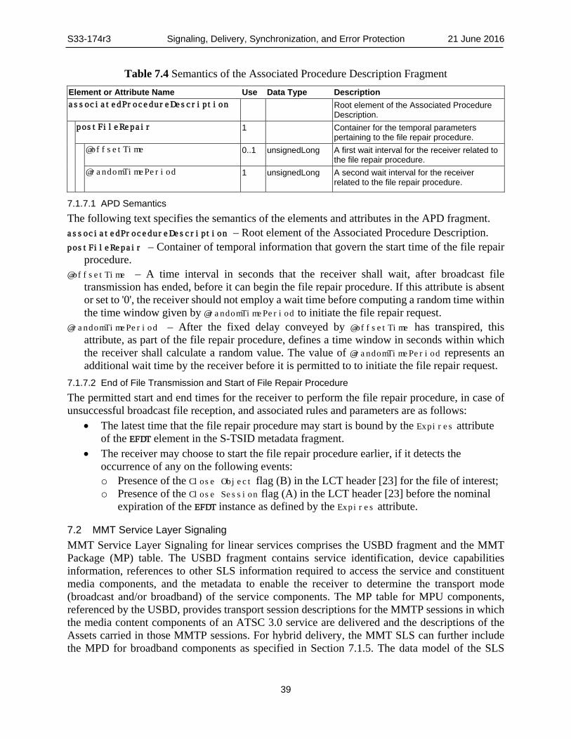
S33-174r3 Signaling, Delivery, Synchronization, and Error Protection 21 June 2016
39
Table 7.4 Semantics of the Associated Procedure Description Fragment
7.1.7.1 APD Semantics The following text specifies the semantics of the elements and attributes in the APD fragment. associatedProcedureDescription – Root element of the Associated Procedure Description. postFileRepair – Container of temporal information that govern the start time of the file repair
procedure. @offsetTime – A time interval in seconds that the receiver shall wait, after broadcast file
transmission has ended, before it can begin the file repair procedure. If this attribute is absent or set to '0', the receiver should not employ a wait time before computing a random time within the time window given by @randomTimePeriod to initiate the file repair request.
@randomTimePeriod – After the fixed delay conveyed by @offsetTime has transpired, this attribute, as part of the file repair procedure, defines a time window in seconds within which the receiver shall calculate a random value. The value of @randomTimePeriod represents an additional wait time by the receiver before it is permitted to to initiate the file repair request.
7.1.7.2 End of File Transmission and Start of File Repair Procedure The permitted start and end times for the receiver to perform the file repair procedure, in case of unsuccessful broadcast file reception, and associated rules and parameters are as follows:
• The latest time that the file repair procedure may start is bound by the Expires attribute of the EFDT element in the S-TSID metadata fragment.
• The receiver may choose to start the file repair procedure earlier, if it detects the occurrence of any on the following events: o Presence of the Close Object flag (B) in the LCT header [23] for the file of interest; o Presence of the Close Session flag (A) in the LCT header [23] before the nominal
expiration of the EFDT instance as defined by the Expires attribute.
7.2 MMT Service Layer Signaling MMT Service Layer Signaling for linear services comprises the USBD fragment and the MMT Package (MP) table. The USBD fragment contains service identification, device capabilities information, references to other SLS information required to access the service and constituent media components, and the metadata to enable the receiver to determine the transport mode (broadcast and/or broadband) of the service components. The MP table for MPU components, referenced by the USBD, provides transport session descriptions for the MMTP sessions in which the media content components of an ATSC 3.0 service are delivered and the descriptions of the Assets carried in those MMTP sessions. For hybrid delivery, the MMT SLS can further include the MPD for broadband components as specified in Section 7.1.5. The data model of the SLS
Element or Attribute Name Use Data Type Description associatedProcedureDescription Root element of the Associated Procedure
Description. postFileRepair 1 Container for the temporal parameters
pertaining to the file repair procedure. @offsetTime 0..1 unsignedLong A first wait interval for the receiver related to
the file repair procedure. @randomTimePeriod 1 unsignedLong A second wait interval for the receiver
related to the file repair procedure.

S33-174r3 Signaling, Delivery, Synchronization, and Error Protection 21 June 2016
40
applicable to MMT linear services, shown using UML convention, shall be as shown in Figure 7.3.
The streaming content signaling component of the SLS for MPU components shall correspond to the MP table defined in Section 9.3.9 of ISO/IEC 23008-1 [30]. The MP table provides a list of MMT Assets where each Asset corresponds to a single service component and the description of the location information for this component. The MP table shall be further described as in Section 7.2.3.
USBD fragments may also contain a reference to the S-TSID as specified in Section 7.1.4 for locally-cached service content delivered by the ROUTE protocol.
1 includes 1User
ServiceBundle
Desciprtion
1
references
1
0..1
1
references
userServiceDesciprtion
MMTPackage
TableMedia
PresentationDescription
(for broadbandcomponents)
Figure 7.3 Service Layer Signaling data model for Linear Services.
User Service Description for MMT The top level or entry point SLS fragment is the USBD fragment. The USBD fragment for ATSC 3.0 is modeled on the USBD fragment (bundleDescription) as defined by MBMS [9], with the following extensions:
• Child attribute serviceId under the element userServiceDescription • Child element contentAdvisoryRating under the element userServiceDescription; • Child element Channel and its child attributes serviceGenre, serviceIcon, and child
element ServiceDescription and its child attributes serviceDescrTex, serviceDescrLang under the element userServiceDescription;
• Child element mpuComponent and its child attributes mmtPackageID and nextMMTPackageID,contendIdschemdIdUri, contentIdvalue, nextMmtPackageId, nextContentIdSchemeIdUri and nextContentIdValue under the element userServiceDescription;
• Child element routeComponent and its child attributes sTSIDUri, apdURI sTSIDDestinationIpAddress, sTSIDDestinationUdpPort, sTSIDSourceIPAddress, sTSIDMajorProtocolVersion, sTSIDMinorProtocolVersion under the element userServiceDescription, as service signaling data to support the delivery of locally-cached service content via ROUTE protocol;

S33-174r3 Signaling, Delivery, Synchronization, and Error Protection 21 June 2016
41
• Child element broadbandComponent and its child attributes fullMPDUri under the element userServiceDescription; and
• Child element ComponentInfo and its child attributes componentType, componentRole, componentProtectedFlag, componentId, componentName under the element userServiceDescription.
It is recommended that the same information should not be repeated in the MMT USBD when it is carried in the service announcement. In this case information in Service Announcement should take precedence.
A large number of the attributes and elements in the MBMS USBD fragment are optional and not relevant to ATSC 3.0. Table 7.5 shows the elements and attributes that would be used in practice for ATSC 3.0 service delivery.
The bundleDescription shall be represented as an XML document containing a bundleDescription root element that conforms to the definitions in the XML schema that has namespace:
http://www.atsc.org/XMLSchemas/ATSC3/Delivery/MMTUSD/1.0/
The definition of these schemas are in schema files accompanying this standard, as described in Section 3.6 above.
While the XML schemas identified above specify the normative syntax of the elements specified in this ATSC 3.0 standard, informative Table 7.5 below describes the structure of the bundleDescription element of MBMS [9], including the ATSC extensions, in a more illustrative way.

S33-174r3 Signaling, Delivery, Synchronization, and Error Protection 21 June 2016
42
Table 7.5 XML Format of the User Service Bundle Description Fragment for MMT
Element or Attribute Name Use Data Type Description
bundleDescription Root element of the User Service
Bundle Description. userServiceDescription A single instance of an ATSC 3.0
Service. @globalServiceID 1 anyURI A globally unique URI that identifies
the ATSC 3.0 Service. @serviceId 1 unsignedShort Reference to corresponding service
entry in LLS(SLT). Name 0..N string Name of the ATSC 3.0 service. @lang 1 xml: lang Language of the ATSC 3.0 service
name. serviceLanguage 0..N string Available languages of the ATSC 3.0
service contentAdvisoryRating 0..N Specifies the content advisory rating,
as defined in the ATSC 3.0 Service Announcement specification [4].
Channel 1 Contains information about the service
@serviceGenre 0..1 unsignedByte Attribute indicates primary genre of the service..
@serviceIcon 1 anyURI Attribute indicates the Uniform Resource Locator (URL) for the icon used to represent this service.
ServiceDescription 0..N Contains service description possibly in multiple languages.
@serviceDescrText 1 string Attribute indicates description of the service.
@serviceDescrLang 0..1 string Attribute indicates the language of the serviceDescrText.
mpuComponent
0..1 A description about the contents components of ATSC 3.0 Service delivered as MPUs
@mmtPackageId 1 string Reference to a MMT Package for content components of the ATSC 3.0 Service delivered as MPUs.
@contentIdSchemeUri 0..1 anyURI Attribute indicates a URI to identify the scheme for Content ID associated to the current MMT Package.
@contentIdValue 0..1 string Attribute indicates the value for Content ID associated to the current MTT Package.
@nextMmtPackageId 0..1 string Reference to a MMT Package to be used after the one referenced by @mmtPackageId in time for content components of the ATSC 3.0 Service delivered as MPUs.
@contentIdSchemeUri 0..1 anyURI Attribute indicates a URI to identify the scheme for Content ID associated to the current MMT Package..

S33-174r3 Signaling, Delivery, Synchronization, and Error Protection 21 June 2016
43
@contentIdValue 0..1 string Attribute indicates the value for Content ID associated to the current MTT Package.
routeComponent 0..1 A description about locally-cached service content of ATSC 3.0 Service delivered by ROUTE.
@sTSIDUri 1 anyURI Reference to the S-TSID fragment which provides access related parameters to the Transport sessions carrying contents of this ATSC 3.0 Service.
@apdURI 0..1 anyURI Reference to the APD fragment which contains file repair related information.
@sTSIDDestinationIpAddress 0..1 string (IP Address)
A string containing the dotted-IPv4 destination address of the packets carrying S-TSID for this service.
@sTSIDDestinationUdpPort 1 unsignedShort (port)
Port number of the packets carrying S-TSID for this service.
@sTSIDSourceIpAddress 1 string (IP address)
A string containing the dotted-IPv4 source address of the packets carrying S-TSID for this service.
@sTSIDMajorProtocolVersion 0..1 unsignedByte Major version number of the protocol used to deliver the S-TSID for this service.
@sTSIDMinorProtocolVersion 0..1 unsignedByte Minor version number of the protocol used to deliver the S-TSID for this service.
broadbandComponent 0..1 A description about the contents components of ATSC 3.0 Service delivered by broadband.
@fullMPDUri 1 anyURI Reference to an MPD fragment which contains descriptions for contents components of the ATSC 3.0 Service delivered over broadband.
ComponentInfo 1..N Contains information about components available in the service. For each component includes information about component type, component role, component name, component identifier, component protection flag.
@componentType 1 unsignedByte Attribute indicates the type of this component.
@componentRole 1 unsignedByte Attribute indicates the role or kind of this component.
@componentProtectedFlag 0..1 boolean Attribute indicates if this component is protected
@componentId 1 string Attribute indicates the identifier of this component.
@componentName 0..1 string Attribute indicates the human readable name of this component.

S33-174r3 Signaling, Delivery, Synchronization, and Error Protection 21 June 2016
44
7.2.1.1 User Service Description for MMT – Semantics The following text specifies the semantics of the elements and attributes in the User Service Description for MMT. bundleDescription – Root element of the User Service Bundle Description. userServiceDescription – Single instance of an ATSC 3.0 Service. @globalServiceID – A globally unique URI that identifies the ATSC 3.0 Service. This parameter
is used to link to ESG data (Service@globalServiceID). Same as given in Table 7.1. @serviceId – Reference to corresponding service entry in LLS (SLT). The value of this attribute
is the same value of serviceId assigned to the service entry. Same as given in Table 7.1. Name – Name of the ATSC 3.0 service in the language specified by @lang attribute. (Same as given
in Table 7.1). @lang – Language of the ATSC 3.0 service name. The language shall be specified according to
BCP 47 [24]. (Same as given in Table 7.1). serviceLanguage – Available languages of the ATSC 3.0 service. The language shall be specified
according to BCP 47 [24]. (Same as given in Table 7.1). contentAdvisoryRating – Specifies the content advisory rating, as defined in the ATSC 3.0
Service Announcement specification [4]. The format of this element shall be identical to the ContentAdvisoryRatings element specified in the Service fragment of the ATSC 3.0 Service Announcement specification [4].
Channel – This element contains information about the service. @serviceGenre – This attribute indicates primary genre of the service. This attribute shall be
instantiated to describe the genre category for the service. The <classificationSchemeURI> is http://www.atsc.org/XMLSchemas/mh/2009/1.0/genre-cs/ and the value of serviceGenre shall match a termID value from the classification schema in Annex B of A/153 Part 4 [5].
@serviceIcon – This attribute indicates the Uniform Resource Locator (URL) for the icon used to represent this service.
ServiceDescription – Contains service description possibly in multiple languages. @serviceDescrText – This attribute indicates description of the service. @serviceDescrLang – This attribute indicates the language of the serviceDescrText. Semantics
of xs:lang shall be followed. mpuComponent – A description about the contents components of ATSC 3.0 Service delivered as
MPUs. @mmtPackageId – Reference to a MMT Package for content components of the ATSC 3.0 Service
delivered as MPUs. @contentIdschemeIdUri – This attribute shall indicate a URI to identify the scheme for Content
ID associated to the current MMT Package. The semantics of @contentIdValue attribute are specific to the scheme specified by this attribute. The allowed values are: • urn:eidr for EIDR Contend ID • tag:atsc.org,2016:cid:adid for Ad-ID Content ID • tag:atsc.org,2016:cid:x-<abbrev> for user private Content ID system, where
<abbrev> is a suitable abbreviation for the content ID system. Experimental or proprietary Content ID systems can be supported by replacing “adid” in
the contentIdSchemeIdUri for Ad-ID Content ID with a designation of form “x-<abbrev>”

S33-174r3 Signaling, Delivery, Synchronization, and Error Protection 21 June 2016
45
for the experimental or proprietary Contend ID system, where <abbrev> is a suitable abbreviation for the content ID system. When doing this, care must be taken that the <abbrev> used is not duplicated for any other experimental or proprietary Content ID system for the same service. The user private Content ID system could be, for example, House Numbers or some other identifier system used by a broadcaster.
@contentIdvalue – This attribute shall specify the value of Content ID associated to the current MMT Package according to the Contend ID system identified by @contentIdSchemeIdUri attribute. The “EIDR Content ID” shall be the canonical form of an EIDR ID registered with the Entertainment Identifier Registry. (See the eidr.org web site.) The “Ad-ID Content ID” shall be an Ad-ID code registered with the Ad-ID system developed by the American Association of Advertising Agencies and the Association of National Advertisers. (See the www.ad-id.org web site.)
@nextMmtPackageId – Reference to a MMT Package to be used after the one referenced by @mmtPackageId in time for content components of the ATSC 3.0 Service delivered as MPUs.
@nextContentIdschemeIdUri – This attribute shall indicate a URI to identify the scheme for Content ID associated to the next MMT Package. The semantics of @nextContentIdValue attribute are specific to the scheme specified by this attribute. The allowed values are: • urn:eidr for EIDR Contend ID • tag:atsc.org,2016:cid:adid for Ad-ID Content ID • tag:atsc.org,2016:cid:x-<abbrev> for user private Content ID system, where
<abbrev> is a suitable abbreviation for the content ID system. Experimental or proprietary Content ID systems can be supported by replacing “adid” in
the nextContentIdSchemeIdUri for Ad-ID Content ID with a designation of form “x-<abbrev>” for the experimental or proprietary Contend ID system, where <abbrev> is a suitable abbreviation for the content ID system. When doing this, care must be taken that the <abbrev> used is not duplicated for any other experimental or proprietary Content ID system for the same service. The user private Content ID system could be, for example, House Numbers or some other identifier system used by a broadcaster.
@nextContentIdvalue – This attribute shall specify the value of Content ID associated to the next Package according to the Contend ID system identified by @nextContentIdSchemeIdUri attribute. The “EIDR Content ID” shall be the canonical form of an EIDR ID registered with the Entertainment Identifier Registry. (See the eidr.org web site.) The “Ad-ID Content ID” shall be an Ad-ID code registered with the Ad-ID system developed by the American Association of Advertising Agencies and the Association of National Advertisers. (See the www.ad-id.org web site.)
routeComponent – A description about the contents components of ATSC 3.0 Service delivered by ROUTE.
@sTSIDUri – Reference to the S-TSID fragment which provides service access related parameters to the Transport sessions carrying contents of this ATSC 3.0 Service (same as given in Table 7.1).
@apdURI – This optional attribute shall provide a reference to the APD fragment which provides file repair related information for the content components of ATSC 3.0 Service delivered by ROUTE. This attribute points to an APD fragment as described in Section 7.1.7.

S33-174r3 Signaling, Delivery, Synchronization, and Error Protection 21 June 2016
46
When @apdURI is present, at least one Alternate-Content-Location-1 element shall be present in the EFDT element of the S-TSID fragment pointed by the routeComponent @sTSIDUri.
@sTSIDDestinationIpAddress – A string containing the dotted-IPv4 destination address of the packets carrying S-TSID for this service. When not present the value of this attribute is inferred to be current MMTP session’s destination IP address.
@sTSIDDestinationUdpPort – A string containing the UDP port number of the packets carrying S-TSID for this service.
@sTSIDSourceIpAddress – A string containing the dotted-IPv4 source address of the packets carrying S-TSID for this service.
@sTSIDMajorProtocolVersion – Major version number of the protocol used to deliver the S-TSID for this service. When not present the value of this attribute is inferred to be 1.
@sTSIDMinorProtocolVersion – Minor version number of the protocol used to deliver the S-TSID for this service. When not present the value of this attribute is inferred to be 0.
broadbandComponent – A description about the contents components of ATSC 3.0 Service delivered by broadband.
@fullMPDUri – Reference to an MPD fragment which contains descriptions for content components of the ATSC 3.0 Service delivered over broadband.
ComponentInfo – Contains information about components available in the service. For each component includes information about component type, component role, component name, component identifier, component protection flag.
@componentType – This attribute indicates the type of this component. Value of 0 indicates an audio component. Value of 1 indicates a video component. Value of 2 indicates a closed caption component. Values 3 to 7 are reserved.
@componentRole – This attribute indicates the role or kind of this component. For audio (when componentType attribute above is equal to 0): values of componentRole
attribute are as follows: 0 = Complete main, 1 = Music and Effects, 2 = Dialog, 3 = Commentary, 4 = Visually Impaired, 5 = Hearing Impaired, 6 = Voice-Over, 7-254= reserved, 255 = unknown.
For Video (when componentType attribute above is equal to 1) values of componentRole attribute are as follows: 0 = Primary video, 1-254 = reserved, 255 = unknown.
For Closed Caption component (when componentType attribute above is equal to 2) values of componentRole attribute are as follows: 0 = Normal, 1 = Easy reader, 2-254 = reserved, 255 = unknown.
When @componentType attribute above has a value is between 3 to 7, inclusive, the @componentRole value shall be equal to 255.
@componentProtectedFlag – This attribute indicates if this component is protected (e.g. encrypted). When this flag is set to a value of 1 this component is protected (e.g. encrypted). When this flag is set to a value of 0 this component is not protected (e.g. encrypted). When not present the value of componentProtectedFlag attribute is inferred to be equal to 0.
@componentId – This attribute indicates the identifier of this component. The value of this attribute shall be the same as the asset_id in the MP table corresponding to this component.
@componentName – This attribute indicates the human readable name of this component.

S33-174r3 Signaling, Delivery, Synchronization, and Error Protection 21 June 2016
47
Media Presentation Description (MPD) The Media Presentation Description is an SLS metadata fragment corresponding to a linear service of a given duration defined by the broadcaster (for example a single TV program, or the set of contiguous linear TV programs over a period of time). The contents of the MPD provide the resource identifiers for Segments and the context for the identified resources within the Media Presentation. The data structure and semantics of the MPD shall be according to the Media Presentation Description as defined by the DASH-IF [8] profile of MPEG DASH [47].
To ensure seamless playback across Period boundaries, ahead of the Period boundary an MPD must be provided which includes both the current Period and the next Period. The MPD describing the next Period must be provided at minimum some amount of time before the end of the current Period (i.e., the Period for which Media Segments are currently being presented). The minimum timing is specified in DASH-IF [8] profile.
In the context of ATSC 3.0 services, an MPD delivered by an MMTP session shall only describe Representations delivered over broadband, e.g. in the case of a hybrid service, or to support service continuity in handoff from broadcast to broadband due to broadcast signal degradation (e.g. driving under a mountain or through a tunnel).
MMT Signaling Message When MMTP sessions are used to carry an ATSC 3.0 streaming service, MMT signaling messages specified in clause 9 of ISO/IEC 23008-1 [30] are delivered in binary format by MMTP packets according to Signaling Message Mode specified in subclause 8.3.4 of ISO/IEC 23008-1 [30]. The value of the packet_id field of MMTP packets carrying Service Layer Signaling shall be set to 0x0000 except for MMTP packets carrying MMT signaling messages specific to an Asset, which shall be set to the same packet_id value as the MMTP packets carrying the Asset. Identifiers referencing the appropriate Package for each ATSC 3.0 Service are signaled by the USBD fragment as described in Table 7.5. MMT Package Table (MPT) messages with matching MMT_package_id shall be delivered on the MMTP session signaled in the SLT. Each MMTP session carries MMT signaling messages specific to its session or each asset delivered by the MMTP session.
The following MMTP messages shall be delivered by the MMTP session signaled in the SLT: • MMT Package Table (MPT) message: This message carries an MP (MMT Package) table
which contains the list of all Assets and their location information as specified in 9.3.4 of ISO/IEC 23008-1) [30].
• MMT ATSC3 (MA3) message mmt_atsc3_message(): This message carries system metadata specific for ATSC 3.0 services including Service Layer Signaling as specified in Section 7.2.3.1.
The following MMTP messages shall be delivered by the MMTP session signaled in the SLT, if required:
• Media Presentation Information (MPI) message: This message carries an MPI table which contains the whole document or a subset of a document of presentation information. An MP table associated with the MPI table also can be delivered by this message (see subclause 9.3.3 of ISO/IEC 23008-1) [30];
The following MMTP messages shall be delivered by MMTP sessions carrying streaming content:
• Hypothetical Receiver Buffer Model message: This message carries information required by the receiver to manage its buffer (see subclause 9.4.2 of ISO/IEC 23008-1 [30]);

S33-174r3 Signaling, Delivery, Synchronization, and Error Protection 21 June 2016
48
• Hypothetical Receiver Buffer Model Removal message: This message carries information required by the receiver to manage its MMT de-capsulation buffer (see subclause 9.4.9 of ISO/IEC 23008-1) [30];
7.2.3.1 mmt_atsc3_message() MMT Signaling Message An MMT Signaling message mmt_atsc3_message() is defined to deliver information specific to ATSC 3.0 services. The value of 0x8100 in the range of user private use shall be assigned for the message_id of mmt_atsc3_message() as per subclause 9.7 of ISO/IEC 23008-1 [30]. The syntax of this message shall be as provided in Table 7.6.
The text following Table 7.6 shall describe the semantics of each field in mmt_atsc3_message().
Table 7.6 Bit Stream Syntax for mmt_atsc3_message() Syntax No. of Bits Format mmt_atsc3_message() { message_id 16 uimsbf version 8 uimsbf length 32 uimsbf message payload { service_id 16 uimsbf atsc3_message_content_type 16 uimbsf atsc3_message_content_version 8 uimbsf atsc3_message_content_compression 8 uimbsf URI_length 8 uimbsf for (i=0;i< URI_length;i++) { URI_byte 8 uimsbf } atsc3_message_content_length 32 uimsbf for (i=0;i<atsc3_message_content_length;i++) { atsc3_message_content_byte 8 uimsbf } for (i=0;i<length-11-URI_length-atsc3_message_content_length) { reserved 8 uimsbf } } }
message_id – A 16-bit unsigned integer field that shall uniquely identify the mmt_atsc3_message(). The value of this field shall be 0x8100.
version – An 8-bit unsigned integer field that shall be incremented by 1 any time there is a change in the information carried in this message. When the version field reaches its maximum value of 255, its value shall wraparound to 0.
length – A 32-bit unsigned integer field that shall provide the length of mmt_atsc3_message() in bytes, counting from the beginning of the next field to the last byte of the mmt_atsc3_message().
service_id – A 16-bit unsigned integer field that shall associate the message payload with the service identified in the serviceId attribute given in the SLT.
atsc3_message_content_type – A 16-bit unsigned integer field that shall uniquely identify the type of message content in the mmt_atsc3_message() payload, coded per Table 7.7 below.

S33-174r3 Signaling, Delivery, Synchronization, and Error Protection 21 June 2016
49
Table 7.7 Code Values for atsc3_message_content_type atsc3_message_content_type Meaning 0x0000 Reserved 0x0001 userServiceDescription as given in Table 7.5. 0x0002 MPD as given in MPEG DASH [47]. 0x0003 Application Signaling Table as given in A/337, Application Signaling and Triggers
[39]. 0x0004 Application Event Information as given in A/337, Application Signaling and Triggers
[39]. 0x0005 Video Stream Properties Descriptor (Sec. 7.2.3.2) 0x0006 ATSC Staggercast Descriptor (Sec. 7.2.3.3) 0x0007 Inband Event Descriptor as given in A/337, Application Signaling and Triggers [39]. 0x0008 Caption Asset Descriptor as given in Section 7.3 of A/343, Captions and Subtitles
[6]. 0x0009~0xFFFF Reserved for future use
atsc3_message_content_version – An 8-bit unsigned integer field that shall be incremented by 1 any time there is a change in the atsc3_message content identified by a service_id and atsc_message_content_type pair. When the atsc3_message_content_version field reaches its maximum value, its value shall wrap around to 0.
atsc3_message_content_compression – An 8-bit unsigned integer field that shall identify the type of compression applied to the data in atsc3_message_content_byte.
Table 7.8 Code Values for atsc3_message_content_compression atsc3_message_content_compression Meaning 0x00 Reserved 0x01 No compression has been applied 0x02 gzip specified in RFC 1952 [11] has been applied 0x03 The template-based compression scheme as specified in Annex D has
been applied 0x04~0xFF Reserved for future use
URI_length – An 8-bit unsigned integer field that shall provide the length of the URI uniquely identifying the message payload across services. If the URI is not present, the value of this field shall be set to 0.
URI_byte – An 8-bit unsigned integer field that shall contain a UTF-8 character of the URI associated with the content carried by this message excluding the terminating null character, as per RFC 3986 [16]. This field when present shall be used to identify delivered message payloads. The URI can be used by system tables to reference tables made available by delivered message payloads.
atsc3_message_content_length – A 32-bit unsigned integer field that shall provide the length of the content carried by this message.
atsc3_message_content_byte – An 8-bit unsigned integer field that shall contain a byte of the content carried by this message.

S33-174r3 Signaling, Delivery, Synchronization, and Error Protection 21 June 2016
50
7.2.3.2 Video Stream Properties Descriptor Each video asset video_stream_properties_descriptor() provides information about its associated video stream. This includes information about resolution, chroma format, bit depth, temporal scalability, bit-rate, picture-rate, 3D, color characteristics, profile, tier, and level. 7.2.3.2.1 Syntax
The syntax for the video_stream_properties_descriptor() shall conform to Table 7.9. The semantics of the fields in the video_stream_properties_descriptor() shall be as given immediately below the table.
Table 7.9 Bit Stream Syntax for Video Stream Properties Descriptor Syntax No. of Bits Format video_stream_properties_descriptor() { descriptor_tag 16 uimsbf descriptor_length 16 uimsbf number_of_assets 8 uimsbf for (i=0;i<number_of_assets;i++) { asset_id_length 8 uimsbf for (i=0; i<asset_id_length; i++) { asset_id_byte 8 uimsbf } codec_code 4*8 uimsbf temporal_scalability_present 1 bslbf scalability_info_present 1 bslbf multiview_info_present 1 bslbf res_cf_bd_info_present 1 bslbf pr_info_present 1 bslbf br_info_present 1 bslbf color_info_present 1 bslbf reserved 1 ‘1’ if (temporal_scalability_present) { max_sub_layers_instream /* s */ 6 uimsbf sub_layer_profile_tier_level_info_present 1 bslbf reserved 1 ‘1’ tid_max 3 uimsbf tid_min 3 uimsbf reserved2 2 ‘11’ } if (scalability_info_present) { scalability_info() 8 Table 7.10 } if (multiview_info_present) { multiview_info() 40 Table 7.11 } if (res_cf_bd_info_present) { res_cf_bd_prop_info() 48 Table 7.12 } if (pr_info_present) { if (sub_layer_profile_tier_level_info_present) {

S33-174r3 Signaling, Delivery, Synchronization, and Error Protection 21 June 2016
51
pr_info(max_sub_layers_instream-1) var Table 7.13 } else { pr_info(0) var Table 7.13 } } if (br_info_present) { if (sub_layer_profile_tier_level_info_present) { br_info(max_sub_layers_instream-1) 32*(s-1) Table 7.14 } else { br_info(0) 32 Table 7.14 } } if (color_info_present) { color_info() var Table 7.15 } if (sub_layer_profile_tier_level_info_present) { profile_tier_level(1,max_sub_layers_instream-1) var H.265 } else { profile_tier_level(1,0) var H.265 } } }
descriptor_tag – This 16-bit unsigned integer shall have the value 0x0005, identifying this descriptor as the video_stream_properties_descriptor().
descriptor_length – This 16-bit unsigned integer shall specify the length (in bytes) immediately following this field up to the end of this descriptor.
number_of_assets – An 8-bit unsigned integer field that shall specify the number of video assets described by this descriptor.
asset_id_length – This 8-bit unsigned integer field shall specify the length in bytes of the video asset id.
asset_id_byte – An 8-bit unsigned integer field that shall contain a byte of the video asset id.. codec_code – This field shall specify a 4-character code for a codec. For this version of this
specification the value of these four characters shall be one of 'hev1', 'hev2', 'hvc1', 'hvc2', 'lhv1' or 'lhe1' with semantic meaning for these codes as specified in ISO/IEC 14496-15 [29].
temporal_scalability_present – This 1-bit Boolean flag shall indicate, when set to ‘1’, that the elements max_sub_layers_present and sub_layer_profile_tier_level_info_present are present and temporal scalability is provided in the asset. When set to ‘0’, the flag shall indicate that the elements max_sub_layers_present and sub_layer_profile_tier_level_info_present are not present and temporal scalability is not provided in the asset.
scalability_info_present – This 1-bit Boolean flag shall indicate, when set to ‘1’, that the elements in the scalability_info() structure are present. When set to ‘0’, the flag shall indicate that the elements in the scalability_info() structure are not present.
multiview_info_present – This 1-bit Boolean flag shall indicate, when set to ‘1’, that the elements in the multiview_info() structure are present. When set to ‘0’, the flag shall indicate that the elements in the multiview_info() structure are not present.

S33-174r3 Signaling, Delivery, Synchronization, and Error Protection 21 June 2016
52
res_cf_bd_info_present – This 1-bit Boolean flag shall indicate, when set to ‘1’, that the elements in the res_cf_bd_info() structure are present. When set to ‘0’, the flag shall indicate that the elements in the res_cf_bd_info() structure are not present.
pr_info_present – This 1-bit Boolean flag shall indicate, when set to ‘1’, that the elements in the pr_info() structure are present. When set to ‘0’, the flag shall indicate that the elements in the pr_info() structure are not present.
br_info_present – This 1-bit Boolean flag shall indicate, when set to ‘1’, that the elements in the br_info() structure are present. When set to ‘0’, the flag shall indicate that the elements in the br_info() structure are not present.
color_info_present – This 1-bit Boolean flag shall indicate, when set to ‘1’, that the elements in the color_info() structure are present. When set to ‘0’, the flag shall indicate that the elements in the color_info() structure are not present.
max_sub_layers_instream – This 6-bit unsigned integer shall specify the maximum number of temporal sub-layers that may be present in each Coded Video Sequence (CVS) in the asset. The value of max_sub_layers_instream shall be in the range of 1 to 7, inclusive.
sub_layer_profile_tier_level_info_present – This 1-bit Boolean flag shall indicate, when set to ‘1’, that profile, tier, and level information be present for temporal sub-layers in the asset. When set to ‘0’, the flag shall indicate that the profile, tier, and level information is not present for temporal sub-layers in the asset. When not present sub_layer_profile_tier_level_info_present shall be inferred to be equal to 0.
tid_max – This 3-bit field shall indicate the maximum value of TemporalId (as defined in Rec. ITU-T H.265 [31]) of all access units for this video asset. tid_max shall be in the range of 0 to 6, inclusive. tid_max shall be greater than or equal to tid_min.
tid_min – This 3-bit field shall indicate the minimum value of TemporalId (as defined in Rec. ITU-T H.265 [31]) of all access units for this video asset. tid_min shall be in the range of 0 to 6, inclusive.
profile_tier_level(profileFPResentFlag, maxSubLayersMinus1) – This variable-sized field shall provide the profile, tier, level syntax structure as described in H.265 (10/2014) HEVC specification Section 7.3.3 [31].
7.2.3.2.1.1 Scalability Information
Table 7.10 Bit Stream Syntax for Scalability Information Syntax No. of Bits Format scalability_info() { asset_layer_id 6 uimsbf reserved 2 ‘11’ }
asset_layer_id – This 6-bit unsigned integer field shall specify the nuh_layer_id [31] for this asset. The value of asset_layer_id shall be in the range of 0 to 62, inclusive. When the value of scalable_info_present is equal to 1 or the value of multiview_info_present is equal
to 1, the Dependency Descriptor specified in Section 9.5.3 of MMT specification [30] shall be included in MPT for each asset. In this case the num_dependencies element in MMT Dependency Descriptor shall indicate the number of layers that the asset_layer_id for this asset is dependent on.

S33-174r3 Signaling, Delivery, Synchronization, and Error Protection 21 June 2016
53
7.2.3.2.1.2 MultiView Information
Table 7.11 Bit Stream Syntax for Multi-View Information Syntax No. of Bits Format multiview_info() { view_nuh_layer_id 6 uimsbf view_pos 6 uimsbf reserved 4 ‘1111’ min_disp_with_offset 11 uimsbf max_disp_range 11 uimsbf reserved 2 ‘11’ }
view_nuh_layer_id – This 6-bit unsigned integer field shall specify the nuh_layer_id [31] for the view represented by this asset. The value of view_nuh_layer_id shall be in the range of 0 to 62, inclusive.
view_pos – This 6-bit unsigned integer field shall specify the order of the view with nuh_layer_id [31] equal to view_nuh_layer_id among all the views from left to right for the purpose of display, with the order for the left-most view being equal to 0 and the value of the order increasing by 1 for next view from left to right. The value of view_pos[ i ] shall be in the range of 0 to 62, inclusive.
Note: multiple video assets having the same view_nuh_layer_id value can have different view_pos values.
min_disp_with_offset – This 11-bit unsigned integer field shall specify minus 1024 of the minimum disparity, in units of luma samples, between pictures of any spatially adjacent views among the applicable views in an access unit. The value of min_disp_with_offset shall be in the range of 0 to 2047, inclusive.
max_disp_range – This 11-bit unsigned integer field shall specify the maximum disparity, in units of luma samples, between pictures of any spatially adjacent views among the applicable views in an access unit. The value of max_disp_range shall be in the range of 0 to 2047, inclusive.

S33-174r3 Signaling, Delivery, Synchronization, and Error Protection 21 June 2016
54
7.2.3.2.1.3 Resolution, Chroma Format, Bit-depth and Video Properties Information:
Table 7.12 Bit Stream Syntax for Resolution, Chroma Format, Bit-Depth Syntax No. of Bits Format res_cf_bd_prop_info() { pic_width_in_luma_samples 16 uimsbf pic_height_in_luma_samples 16 uimsbf chroma_format_idc 2 uimsbf if ( chroma_format_idc == 3 ) { separate_colour_plane_flag 1 bslbf reserved 3 ‘111’ } else { reserved 4 ‘1111’ } video_still_present 1 bslbf video_24hr_pic_present 1 bslbf bit_depth_luma_minus8 4 uimsbf bit_depth_chroma_minus8 4 uimsbf }
pic_width_in_luma_samples, pic_width_in_chroma_samples, chroma_format_idc, separate_colour_plane_flag, bit_depth_luma_minus8, bit_depth_chroma_minus8 elements respectively shall have the same semantic meanings as the elements with the same name in H.265 (10/2014) HEVC specification Section 7.4.3.2 (Sequence parameter set RBSP semantics) [31].
video_still_present – This 1-bit Boolean flag when set to ‘1’, shall indicate that the video asset may include HEVC still pictures as defined in ISO/IEC 13818-1 [28]. When set to ‘0’, the flag shall indicate that the video asset shall not include HEVC still pictures as defined in ISO/IEC 13818-1 [28].
video_24hr_pic_present – This 1-bit Boolean flag when set to ‘1’, shall indicate that the video asset may include HEVC 24-hour pictures as defined in ISO/IEC 13818-1 [28]. When set to ‘0’, the flag shall indicate that the video asset shall not include any HEVC 24-hour picture as defined in ISO/IEC 13818-1 [28].
7.2.3.2.1.4 Picture Rate Information
Table 7.13 Bit Stream Syntax for Picture Rate Information Syntax No. of Bits Format pr_info(maxSubLayersMinus1) { for (i = 0; i <= maxSubLayersMinus1; i++) { picture_rate_code[ i ] 8 uimsbf if( picture_rate_code[ i ] == 255 ) { average_picture_rate[ i ] 16 uimsbf } } }

S33-174r3 Signaling, Delivery, Synchronization, and Error Protection 21 June 2016
55
picture_rate_code[ i ] – This 8-bit unsigned integer field shall provide information about the picture rate for the ith temporal sub-layer of this video asset. The picture_ rate_code[ i ] code indicates following values for picture rate for the ith temporal sub-layer: 0= unknown, 1 = 23.976 Hz, 2 = 24 Hz, 3 = 29.97 Hz, 4 = 30 Hz, 5 = 59.94 Hz, 6 = 60 Hz, 7 = 25 Hz, 8 = 50 Hz, 9 = 100 Hz, 10 = 120/1.001 Hz, 11 = 120 Hz, 12-254 = reserved, 255 = Other. When picture_rate_code[ i ] is equal to 255 the actual value of picture rate shall be indicated by the average_picture_rate[ I ] element.
average_picture_rate[ i ] – This 16-bit unsigned integer field shall indicate the average picture rate, in units of picture per 256 seconds, of the ith temporal sub-layer. The semantics of avg_pic_rate[ 0 ][ i ] defined in H.265 (10/2014) HEVC specification Section F.7.4.3.1.4 (VPS VUI Semantics) [31] shall apply. The average_picture_rate[ i ] shall not have a value corresponding to any of the picture rate values:
23.976 Hz, 24 Hz, 29.97 Hz, 30 Hz, 59.94 Hz, 60 Hz, 25 Hz, 50 Hz, 100 Hz, 120/1.001 Hz, 120 Hz. In this case the picture_rate_code[ i ] shall be used to indicate the picture rate. 7.2.3.2.1.5 Bit Rate Information
Table 7.14 Bit Stream Syntax for Bit Rate Information Syntax No. of Bits Format br_info(maxSubLayersMinus1) { for ( i = 0; i <= maxSubLayersMinus1; i++ ) { average_bitrate[ i ] 16 uimsbf maximum_bitrate[ i ] 16 uimsbf } }
average_bitrate[ i ] – This 16-bit unsigned integer field shall indicate the average bit rate of the ith temporal sub-layer of this video asset in bits per second. The semantics of avg_bit_rate[ 0 ][ i ] defined in H.265 (10/2014) HEVC specification Section F.7.4.3.1.4 (VPS VUI Semantics) [31] shall apply.
maximum_bitrate[ i ] – This 16-bit unsigned integer field shall indicate the maximum bit rate of the ith temporal sub-layer in any one-second time window. The semantics of max_bit_rate[ 0 ][ i ] defined in H.265 (10/2014) HEVC specification Section F.7.4.3.1.4 (VPS VUI Semantics) [31] shall apply.
7.2.3.2.1.6 Color Information

S33-174r3 Signaling, Delivery, Synchronization, and Error Protection 21 June 2016
56
Table 7.15 Bit Stream Syntax for Color Information Syntax No. of Bits Format color_info() { colour_primaries 8 uimsbf transfer_characteristics 8 uimsbf matrix_coeffs 8 uimsbf if (colour_primaries>=9) { cg_compatibility 1 bslbf reserved 7 ‘1111111’ } if (transfer_characteristics>=16) { eotf_info_present 1 bslbf if(eotf_info_present) { eotf_info() var
} } }
colour_primaries, transfer_characteristics, matrix_coeffs elements respectively shall have the same semantics meaning as the elements with the same name in H.265 (10/2014) HEVC specification Section E.3.1 (VUI Parameter Semantics) [31].
cg_compatibility – This 1-bit Boolean flag shall indicate, when set to ‘1’, that the video asset is coded to be compatible with Rec. ITU-R BT.709-5 [34] color gamut. When set to ‘0’, the flag shall indicate that the video asset is not coded to be compatible with Rec. ITU-R BT.709-5 [34] color gamut.
eotf_info_present – This 1-bit Boolean flag shall indicate, when set to ‘1’, that the elements in eotf_info() structure are present. When set to ‘0’, the flag shall indicate that the elements in eotf_info() structure are not present.
eotf_info() – Provides Electro-Optical Transfer Function (EOTF) information data. Note: details are under discussion and will be specified later. For each video asset, a video_stream_properties_descriptor() shall be signaled which includes the
video asset id for the video asset in the asset_id_byte fields of the video_stream_properties_descriptor(). An mmt_atsc3_message() carrying a video_stream_properties_descriptor() shall be signaled for a video asset before delivering any MPU corresponding to the video asset. A video_stream_properties_descriptor() may be used to signal the properties of more than one video asset (by use of the syntax element number_of_assets and the associated for loop with asset_id_bytes field) to which the video_stream_properties_descriptor() applies. 7.2.3.3 ATSC Staggercast Descriptor In order to explicitly signal that an Asset is only suitable for Staggercast, the following shall be done in MMT signaling:
• Signal the Staggercast audio Asset in the list of Assets in the MP table of the service to which the Staggercast Asset belongs to;
• Deliver an ATSC_staggercast_descriptor() (see Table 7.16) using mmt_atsc3_message() that allows signaling the dependency between the Staggercast Asset and the main Asset

S33-174r3 Signaling, Delivery, Synchronization, and Error Protection 21 June 2016
57
protected by it thanks to the presence of the packet_id of the main Asset in the ATSC_staggercast_descriptor().
Table 7.16 Bit Stream Syntax for ATSC Staggercast Descriptor Syntax No. of Bits Format ATSC_staggercast_descriptor() { descriptor_tag 16 uimsbf descriptor_length 16 uimsbf number_of_staggercast_assets 8 uimsbf for (i=0;i<number_of_assets;i++) { staggercast_packet_id 16 uimsbf main_asset_packet_id 16 uimsbf } }
descriptor_tag - This 16-bit unsigned integer shall have the value 0x0006, identifying this descriptor as being the ATSC_staggercast_descriptor().
descriptor_length – This 16-bit unsigned integer shall specify the length (in bytes) immediately following this field up to the end of this descriptor.
number_of_assets – An 8-bit unsigned integer field that shall specify the number of Staggercast Assets described by this descriptor.
staggercast_packet_id – This 16-bit unsigned integer shall indicate the packet_id of a Staggercast Asset.
main_asset_packet_id – indicates which main Asset is protected by the Staggercast Asset. Its value shall be set to the value of the packet_id of the main Asset protected by the Staggercast Asset. If an Asset is annotated with an ATSC_staggercast_descriptor(), the ATSC 3.0 client is expected to
not select such Asset for regular playout. If the ATSC 3.0 receiver supports the Staggercast mechanism, it is expected to buffer both the main audio and the Staggercast audio in order to be able to switch down to the Staggercast audio, should main audio become unavailable.
7.3 Content Advisory Ratings in Service Signaling Content advisory program metadata may refer to a rating system defined in a Rating Region Table, or it may refer to another rating system.
DASH Signaling of RRT-based Content Advisories For RRT-based program ratings, the content advisory rating XML data as specified in the ContentAdvisoryRatings element defined in the ATSC Service Announcement specification [4] is represented in string format using the following rules. The content advisory rating string corresponding to a given rating region shall consist of three parts separated by a comma as a delimiter:
• The first part shall indicate the region identifier coded as an unsigned byte value as specified by ContentAdvisoryRatings.RegionIdentifier element. If the ContentAdvisoryRatings.RegionIdentifier element is not present, an empty first part shall be included for the region identifier. If not present, the value of RegionIdentifier shall be coded as ‘1’.
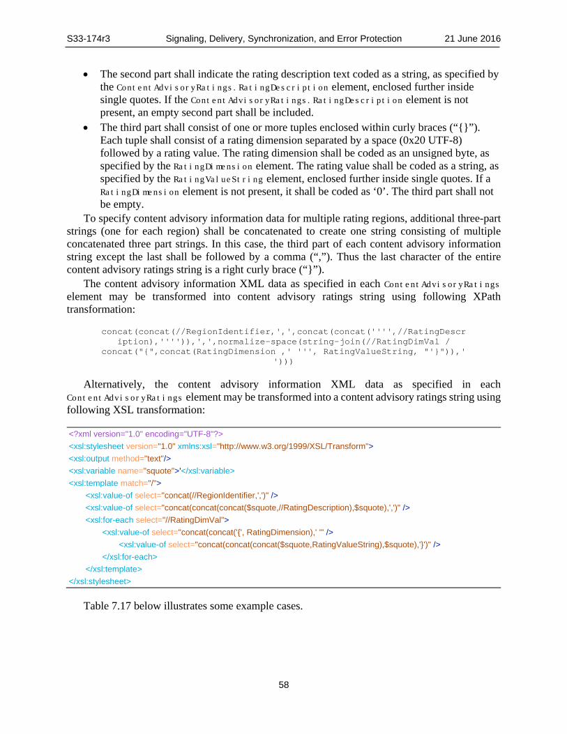
S33-174r3 Signaling, Delivery, Synchronization, and Error Protection 21 June 2016
58
• The second part shall indicate the rating description text coded as a string, as specified by the ContentAdvisoryRatings.RatingDescription element, enclosed further inside single quotes. If the ContentAdvisoryRatings.RatingDescription element is not present, an empty second part shall be included.
• The third part shall consist of one or more tuples enclosed within curly braces (“{}”). Each tuple shall consist of a rating dimension separated by a space (0x20 UTF-8) followed by a rating value. The rating dimension shall be coded as an unsigned byte, as specified by the RatingDimension element. The rating value shall be coded as a string, as specified by the RatingValueString element, enclosed further inside single quotes. If a RatingDimension element is not present, it shall be coded as ‘0’. The third part shall not be empty.
To specify content advisory information data for multiple rating regions, additional three-part strings (one for each region) shall be concatenated to create one string consisting of multiple concatenated three part strings. In this case, the third part of each content advisory information string except the last shall be followed by a comma (“,”). Thus the last character of the entire content advisory ratings string is a right curly brace (“}”).
The content advisory information XML data as specified in each ContentAdvisoryRatings element may be transformed into content advisory ratings string using following XPath transformation:
concat(concat(//RegionIdentifier,',',concat(concat('''',//RatingDescription),'''')),',',normalize-space(string-join(//RatingDimVal /
concat("{",concat(RatingDimension ,' ''', RatingValueString, "'}")),' ')))
Alternatively, the content advisory information XML data as specified in each ContentAdvisoryRatings element may be transformed into a content advisory ratings string using following XSL transformation:
<?xml version="1.0" encoding="UTF-8"?> <xsl:stylesheet version="1.0" xmlns:xsl="http://www.w3.org/1999/XSL/Transform"> <xsl:output method="text"/> <xsl:variable name="squote">'</xsl:variable> <xsl:template match="/"> <xsl:value-of select="concat(//RegionIdentifier,',')" /> <xsl:value-of select="concat(concat(concat($squote,//RatingDescription),$squote),',')" /> <xsl:for-each select="//RatingDimVal"> <xsl:value-of select="concat(concat('{', RatingDimension),' '" /> <xsl:value-of select="concat(concat(concat($squote,RatingValueString),$squote),'}')" /> </xsl:for-each> </xsl:template> </xsl:stylesheet>
Table 7.17 below illustrates some example cases.

S33-174r3 Signaling, Delivery, Synchronization, and Error Protection 21 June 2016
59
Table 7.17 Example Content Advisory Rating Strings Rating Region Program Rating RRT Reference Content Advisory Rating String
1 TV-PG-D-L-S-V
Dimension Level
"1,'TV-PG D-L-S-V',{0 'TV-PG'} {1 'D'}{2 'L'}{3 'S'}{4 'V'}"
0 3 1 1 2 1 3 1 4 1
2
Canadian English Language Rating: 14+
Dimension Level "2,'13+(fr)/14+(en)',{0 '14+'} {1 '13+'}"
0 5 Canadian French Language Rating: 13+ 1 3
In the case that a single program is rated for both rating regions 1 and 2, for the example in Table 7.17, the string would be
"1,'TV-PG D-L-S-V', {0 'TV-PG'}{1 'D'}{2 'L'}{3 'S'}{4 'V'}, 2,'13+(fr)/14+(en)',{0 '14+'}{1 '13+'}"
When using DASH, the ratings value shall be specified by the MPD.Period.AdaptationSet.Rating element. When the content advisory corresponds to a rating system defined by an RRT, the value of Rating@schemeIdUri shall be set equal to "tag:atsc.org,2016:carating:1." The @value string shall be set equal to the content advisory ratings string specified in Section 7.3 above. Alternatively or in addition, content advisories corresponding to other rating systems may be included. For content advisories not corresponding to defined RRTs, different Rating@schemeIdUri values are used, as specified by appropriate regional authorities.
In the DASH MPD, per [47] the Rating element is a child element of AdaptationSet, thus any or all Adaptation Sets in a Period could be labeled with a content advisory. When the entire Program is to be associated with one content advisory rating (the usual case), only one instance of the Rating element with a value of "tag:atsc.org,2016:RRTrating:1" for Rating@schemeIdUri shall be included in the Period as an MPD.Period.AdaptationSet.Rating element. Multiple Rating elements with different values for Rating@schemeIdUri may be included in the Period as MPD.Period.AdaptationSet.Rating elements. In the DASH MPD no ContentComponent element shall include a Rating element.
The rules for placement of a Rating element with a value of "tag:atsc.org,2016:RRTrating:1" for Rating@schemeIdUri shall be as follows:
• When a Period includes only one Adaptation Set containing one or more video components (e.g. those with @mimeType="video/mp4"), the Rating element shall appear in that AdaptationSet.
• When a Period includes multiple Adaptation Sets each with @mimeType="video/mp4" containing video components, the Rating element shall appear in each AdaptationSet among these whose Role@schemeIdUri is equal to "urn:mpeg:dash:role:2011" and Role@value is equal to "main", or the AdaptationSet among these that contains a video component for which the Role@schemeIdUri is equal to "urn:mpeg:dash:role:2011" and Role@value is equal to "main".
S33-174r3 Signaling, Delivery, Synchronization, and Error Protection 21 June 2016
60
When a Period includes no Adaptation Sets describing video componentsi.e. none of the AdaptationSet elements have @mimeType="video/mp4", the Rating element shall appear only in the first AdaptationSet listed in the MPD for that Period.
MMT Signaling of RRT-Based Content Advisories When using MMT, the content advisory rating shall be specified by the atsc:contentAdvisoryRating element in the USBD for MMT as defined in Table 7.5. The format of this element shall be identical to the ContentAdvisoryRatings element specified in the Service fragment of the ATSC 3.0 Service Announcement specification [4].
8. DELIVERY AND AL-FEC
8.1 Broadcast Delivery Two delivery methods for streaming broadcast content are specified in the sections that follow. A method based on ROUTE and ROUTE/DASH is specified in Section 8.1.1. A method based on MMTP/MPU is specified in Section 8.1.2.
Source data may be transmitted with additional repair data that is generated from the source data by applying an AL-FEC algorithm. The repair data enables but does not require application-layer error correction at reception.
ROUTE/DASH The DASH-IF [8] profile of MPEG DASH [47], specifies formats and methods that enable the delivery of streaming service(s) from standard HTTP servers to DASH client(s). DASH specifies the description of a collection of Media Segments and auxiliary metadata (all referenced by HTTP URLs) through a Media Presentation Description (MPD).
The ROUTE protocol is designed to deliver, via broadcast, DASH-formatted streaming content, such as linear TV services, to a large receiver population. It is capable of delivering an arbitrary number of different types of media objects over one or more source flows on LCT channels. Repair flows may be additionally used for certain deployment scenarios, such as to mobile devices, in certain geographical areas, only for certain service, etc. 8.1.1.1 Streaming Services Delivery The MPD shall conform to the DASH-IF [8] interoperability point of the ISO Base Media File Format live profile profile. Regardless of whether a streaming service is delivering live content (e.g. live sports events, real-time news reports), or pre-recorded programming, the MPD@type (attribute ‘type’ of the MPD) shall be set to “dynamic” as defined in ISO/IEC 23009-1 [47]. When MPD@minimumUpdatePeriod is present, the receiver should expect MPD updates to be carried in the LCT channel which provide carousel delivery of Service Layer Signaling (SLS) metadata fragments. The objects delivered by LCT channel of the ROUTE protocol in Annex A shall be formatted according to the announcement in the MPD. The MPD and the described Media Presentation should conform to the DASH-IF [8] live profile of the ISO Base media file format live profile as specified in MPEG DASH [47], clause 8.4.
If it is not possible that the EFDT parameters are determined prior to the object delivery, the Entity Mode (see Annex A Sec. A.3.3.3) shall be used. In this case, the EFDT parameters (as entity-headers) are sent in-band with the delivery object (as the entity-body), in the form of a compound object.
In addition, use of the Entity Mode enables partial or chunked delivery in the same way as HTTP provides a means to reduce the sender delay and therefore possibly the end-to-end delay. If
S33-174r3 Signaling, Delivery, Synchronization, and Error Protection 21 June 2016
61
the File Mode (see Annex A Sec. A.3.3.2) is used, then the file may also be sent in a progressive manner using the regular ROUTE sending operation in order to reduce the sender delay.
In the File Mode, the file/object metadata as represented by the EFDT shall either be embedded within, or shall be referenced as a separate delivery object by, the signaling metadata. In the Entity Mode, the file/object metadata shall be carried by one or more entity-header fields associated with the entity-body. If the repair flow is used in conjunction with the source flow for streaming content delivery, it may use the Packaging mode as the delivery object format as defined in Section A.3.3.4 of Annex A. Doing so enables more robust Application Layer FEC recovery, by applying FEC protection across a collection of delivery objects for enhanced time diversity and constant QoS.
The EXT_TIME LCT extension header defined in RFC 5651 [23] shall be used to provide Sender Current Time (SCT), (SCT-High and SCT-Low are both set). For byte range delivery (MDE mode), the timing information optionally carried shall be the UTC time of the completion of the emission of the entire MDE data block and all related encapsulation in the broadcast emission necessary to decode it. For object delivery, the timing information optionally carried shall be the current UTC time at the sender when the last of byte of an object (last LCT packet) is emitted/radiated. This labeling shall be based on the same time base as is used to deliver time in the PHY layer.
When the first byte of an MDE data block with Random Access Point (RAP) is emitted/radiated, the LCT extension header of the first LCT packet shall include EXT_ROUTE_PRESENTATION_TIME, which shall be the only condition whereby this header is present. The value of EXT_ROUTE_PRESENTATION_TIME (see Annex A 0) shall be set such that the delay (EXT_ROUTE_PRESENTATION_TIME - SCT) is the duration in time that the ROUTE receiver must hold this MDE data block with RAP prior to delivery to the ROUTE output to achieve stall-free playback. This delay time can be derived via characterization of the equipment generating the broadcast emission. The delay value is specific to a particular configuration of the scheduler and encoder, e.g. GOP duration, sequence of RAPs etc. Delivery of data blocks in MDE mode is by definition in-order delivery, so any subsequent data blocks are held until after such time as the leading MDE data block with RAP is delivered to the ROUTE output. 8.1.1.2 Locally-Cached Content Delivery This section specifies file-based delivery of locally-cached service content, and service metadata such as SLS fragments or the ESG.
File contents comprising discrete (i.e. untimed) media are downloaded by the receiver either in response to user selection, or acquired without need for user intervention. The source flow, when delivering file content, should use the File Mode as defined in Annex A as the delivery object format. The file metadata, or equivalently, the EFDT, is assumed to be known, available, and delivered to the receiver before the scheduled delivery of the file. The EFDT is delivered in advance by the S-TSID metadata fragment as defined in Table 7.2. The source flow for the subsequently delivered file shall provide a reference to the LCT channel and file URI. The file URI shall be identical in format to the EFDT@idRef as defined in Table A.3.3, to identify the previously delivered EFDT/file metadata, and in turn, enable the receiver to use the EFDT to process the content file.
From the application transport and IP delivery perspective, service metadata such as SLS or ESG fragments are no different from locally-cached files which belong to an locally-cached content item of an ATSC 3.0 application service. Service metadata delivery by the ROUTE protocol operates the same way as described above for files of locally-cached service contents.

S33-174r3 Signaling, Delivery, Synchronization, and Error Protection 21 June 2016
62
8.1.1.3 Synchronization and Time DASH requires accurate wall clock for synchronization. When a receiving device is connected to ASTC 3.0 broadcast reception, it is expected to utilize UTC as established via the physical layer for wall clock.
Network servers for both broadcast and broadband components of a Service shall synchronize to a common wall clock (UTC) source. GPS or similar accuracy and stability shall be provided.
The broadcast-established wall clock is expected to be utilized for both broadband and broadcast served media components at the receiver at all times. Wall clock (UTC) established via broadband connection is expected to be utilized at the receiver in the absence of the broadcast wall clock source.
Several use cases of receiver presentation time are supported for MPD@type='dynamic'. These are defined as: Earliest MDE ROUTE presentation time, Earliest Segment level DASH presentation time, and Synchronized Segment level DASH presentation timeline. The receiver is expected to calculate the offset of presentation timeline relative to receiver wall clock for two use cases as follows:
1) Earliest MDE ROUTE presentation time: MDE data block with T-RAP ROUTE reception time plus (EXT_ROUTE_PRESENTATION_TIME - SCT). Initial media request based on adjusted segment availability start time per Section 5.3.9.5.3 of [47]6.
2) Segment level DASH presentation time: Segment request based on DASH “Segment availability start time” per the DASH-IF [8] profile of MPEG DASH [47] in which the receiver calculates the presentation timeline based on UTC timing given in the MPD.
Note that DASH provides a mode supporting synchronized playback among different receivers using a parameter called MPD@suggestedPresentationDelay. Broadcast emission of MPD@suggestedPresentationDelay is optional. This mode is not described here as there is no ATSC 3.0 requirement for synchronized playback across multiple devices, and this mode causes an additional delay in channel change times. 8.1.1.4 ROUTE/DASH System Model Figure 8.1 below depicts the ROUTE/DASH System Model. Definitions of terms are given below the figure after a discussion of the distinctions of the ROUTE/DASH System Model as compared to MPEG-2 Systems [28]. Note that there is a single unified model for all types of traffic i.e. there is no required distinction between video, audio, data and system control. Figure 8.1 depicts real time services. For locally-cached and system control services, ROUTE is implemented as depicted by the left hand section of Figure 8.1 with the object(s) terminating in a memory location visible to the appropriate application. In Figure 8.1, the appropriate memory location for media objects is the ROUTE Output Buffer, as shown below.
6 Adjusted segment availability start time is computed by subtracting the value of
@availabilityTimeOffset from the Segment availability start time.

S33-174r3 Signaling, Delivery, Synchronization, and Error Protection 21 June 2016
63
Segment / File Delivery
DASH / ISO BMFF Client
Decoder(s)
j-th access unit k-th presentation unit
All outputs are in Presentation order
t(i)
An(j)tdn(j) D1EBnTBn
m bytes of a Segment / file at time(s) t(i) to
a delivery session buffer MPD
Segments / byte ranges are available at latest
just before demand time
NR
T fil
es to
app
vi
sibl
e lo
catio
n
Dn
...
Pn(k)
P1(k)
tpn(k)
tp1(k)
A1(j)td1(j) D1
P1(k)tp1(k)EB1
RO
UTE
O
utpu
t Buf
fer
Figure 8.1 ROUTE/DASH system model.
There are a number of distinctions for the ROUTE/DASH system relative to the MPEG-2 Systems [28] model. The Data Delivery Events (DDEs) at specific t(i)s are not individual bytes, but rather the result of the delivery of a block of data by the PHY/MAC at a specific time i.e. a discrete data size in bytes at a discrete delivery time.
A TBn buffer is for a specific ROUTE session, rather than an elementary stream. A ROUTE session may deliver multiple objects and related AL-FEC. The specific TBn buffer applies to all the objects and AL-FEC as encapsulated by IP/UDP/ROUTE. The size of TBn is derived via the attribute @minBuffSize as described in the ROUTE specification, Table A.3.1. The size of TBn is the sum of the minBuffSize values for each of the constituent LCT channels.
All events in a ROUTE/DASH model are discrete time based, i.e. “m” bytes input to or “n” bytes output from the buffer at a specific time. Since all events are discrete time for ROUTE/DASH, there are no leakage rates specified.
The delivered objects for media services are very briefly buffered in the ROUTE Output Buffer before they are consumed by the DASH client. The minimum size of this buffer is slightly smaller than the corresponding TBn, as the data in TBn is wrapped in IP/UDP/ROUTE and may include AL-FEC packets. The output objects/files are of course both de-encapsulated and decoded.
The EBn buffer is defined in MPEG-2 Systems [28] as an elementary stream buffer. This buffer, as applied to ROUTE/DASH, is associated with the ISO BMFF file handler, which holds data while it waits to be parsed by the decoders. Given that there may exist multiple object/file streams in an LCT channel, there may be n total EBn (s) associated with a given LCT channel. There may also be “i” media types within a single ISO BMFF file stream and hence the multiple decoders Dn are each connected to a single instance of EBn. The required size of EBn is included as part of the definition of an appropriate DASH profile.
The task of scheduling media to the decoder(s) in the receiver is exclusively the responsibility of the ISO BMFF file handler (within the DASH client). The scheduling of the objects/files to the ISO BMFF handler is part of the DASH function. This described series of steps result in the ISO BMFF handler receiving Media Delivery Events or object(s) that makes contextual and temporal sense and allows it to deliver samples (media frames) to the decoders, such that the media presentation timeline is met.

S33-174r3 Signaling, Delivery, Synchronization, and Error Protection 21 June 2016
64
Unstated so far, but implicit, is that an LCT channel may carry multiple content types, and that content types comprising a service may be available from a collection of separate LCT channels, which belong to one or more ROUTE sessions. It is also significant that the ROUTE/DASH System Model supports continuous streaming with live ad insertions, which may impose some specific constraints with respect to behaviors at DASH Period boundaries.
The operation of the ROUTE/DASH system is defined such that none of the constituent buffers (TBn, EBn, or the ROUTE Output Buffer) are allowed to overflow, nor are the decoder(s) allowed to stall due to lack of input media. Each buffer starts at zero and can likely go to zero briefly during operation. t(i) indicates the time in UTC at which m bytes of the transport stream i.e. a Data Delivery
Event enters the target ROUTE transport buffer (exits top of the PHY/MAC layers). The value t(0) is a specific time in UTC, which is known by the physical layer scheduler.
TBn is the buffer size for the current LCT channel(s) in the ROUTE session, including all source object(s) and all related AL-FEC, as delivered in IP/UDP/ROUTE packets.
EBn is the buffer in the DASH client that holds the received from the ROUTE Output Buffer, until the media is streamed to decoder(s) D1-Dn according to ISO BMFF semantics.
An(j) is the jth access unit in a ROUTE delivery per decoder. An(j) is indexed in decoding order. tdn(j) is the decoding time in UTC of the jth decoded media frame Dn is the decoder for a specific media type per Service definition. Pn(k) is the kth presentation unit for a specific content type. Pn(k) results from decoding An(j).
Pn(k) is indexed in presentation order. tpn(k) is the presentation time in UTC of the kth presentation unit.
8.1.1.5 ROUTE System Buffer Model A valid broadcast emission shall have physical layer resources allocated in such a manner as to ensure that defined constraints on the maximum sizes of TBn, ROUTE Output Buffer and EBn (see Figure 8.1) are not exceeded. A valid broadcast emission shall have physical layer resources allocated in such a manner that buffers in devices that comply with an agreed-upon set of receiver characteristics, e.g. as determined by a standards organization such as CEA, will not overflow or underflow (cause a stall during playback).
The total transport buffer size of the TBn required for a specific ROUTE session shall be defined by adding together the size of the buffer requirements for each LCT channel comprising the ROUTE session. The parameter @minBuffSize specifies the minimum buffer size for each LCT channel. A service may be comprised of multiple ROUTE sessions. 8.1.1.5.1 Data Delivery Event (DDE)
A Data Delivery Event (DDE) occurs when a block-based MAC/PHY delivers relevant contents of a specific physical layer block to a specific ROUTE session at a specific time. Each DDE has a specific time slot at the physical layer and its reception time at the receiver is known by the physical layer scheduler.

S33-174r3 Signaling, Delivery, Synchronization, and Error Protection 21 June 2016
65
8.1.1.5.2 Media Delivery Event (MDE)
A Media Delivery Event (MDE) is the arrival of a collection of bytes that is meaningful to the upper layers of the stack for example the media player and decoder(s). The broadcast emission shall be constructed such that that the delivery deadlines for MDE data blocks are met.
Figure 8.2 below depicts the concept of an MDE data block starting with a Random Access Point (RAP), which becomes a T-MDE starting with a T-RAP once encapsulated in IP/UDP/ROUTE. In the figure, “Meta” represents the collective set of metadata boxes located at the start of a Media Segment, such as styp and sidx. “IS” stands for “Initialization Segment” and contains initializing data that is necessary to present the media streams encapsulated in Media Segments. Figure 8.3 illustrates a “meaningful to upper layer” grouping of video frames. A key aspect is that it has a “required delivery time” to the DASH client at the interface to ROUTE.
* When MDE data block(s) are encapsulated in IP/UDP/ROUTE,then these become T-MDE data block starting with T-RAP
MediaEssence i.e. mdatIS
DASH Segment
MDE data block starting with RAP*
Met
aM
oof
MDEdata block
MDEdata block
MDEdata block
MDEdata block
MDEdata block
MDEdata block
* Once these MDE data blocks(s) are encap-sulated in IP/UDP/ROUTE, they become T-MDE data block(s) starting with T-RAP
Met
a
MPD IS
DASH Media Segment D
MDE data block starting with RAP*
moo
f
DASH Media Segment D
MediaEssence i.e. mdat
MDEMDE MDE MDEMDE MDE
Figure 8.2 Concept of an MDE data block starting with a RAP.

S33-174r3 Signaling, Delivery, Synchronization, and Error Protection 21 June 2016
66
B3
B3
B3
B3
P
B2
B1
B2
I
B3
B3
B3
B2
B1
B2
B3
B3
B3
P
B2
B1
B2
B3
B3
1/24 2/24 4/24
I
PB1B2B3
B3B3B2B3
PB1B2B3
10/24 12/24
B3B3B2B3
B1B2B3
18/24 20/24
B3B3B2B3
Demand Time Relative to 1
Second
MediaDeliveryEvents
MDE MDE MDE MDE MDE MDEMDE Figure 8.3 Illustration of an MDE data block at the video level.
8.1.1.5.3 ROUTE Transport Buffer Model
The transport buffer fullness is completely described by the ROUTE transport buffer model as shown in Figure 8.4 below. The value in the register on the right hand side of the figure denotes transport buffer fullness in bytes.
RegisterSize in bytes at each t with a delivered Data Delivery Event
Notes:
Reset
Size in bytes of all the related transport packets deleted
from the transport buffer, at a time t when a delivery of
object(s) is resolved.
• The register value is the buffer model fullness in bytes for time t at receiver• Service start clears the register, a T-MDE with a T-RAP starts Service• The buffer model updates at every t that transport data will be delivered to
or removed from the transport buffer
Figure 8.4 ROUTE transport buffer model.
A notable aspect of the ROUTE/DASH System Model is the lack of a physical layer buffer. The ROUTE/DASH System Model has no object delivery event, i.e. a complete file required to play the T-MDE data block starting with T-RAP, as the MDE data block with RAP is delivered to the DASH client as soon as allowed, rather than waiting for a complete object.

S33-174r3 Signaling, Delivery, Synchronization, and Error Protection 21 June 2016
67
All the transport data associated with a ROUTE delivery of an MDE data block is retained in the transport buffer until the outcome of that specific ROUTE Segment delivery(s) are resolved. Resolution in this context means that the specific ROUTE delivery of the object(s) succeeded in whole or part, all the related MDE data block deliveries are complete, and all the results have been either posted up to the output buffer or have been abandoned. Upon resolution, all the related packets in the related transport buffer(s) are deleted. If there is FEC as part of the ROUTE delivery, the “related packets” include all those packets in buffers for all the related LCT channels. If an object is exclusively related to a single LCT channel, then the associated per-LCT transport buffer may be managed independently. In all cases the last object/MDE data block in a ROUTE delivery to be resolved and delivered determines when all the related IP/UDP/ROUTE packets get deleted from the associated LCT buffers. 8.1.1.6 Application of AL-FEC (Informative) The availability of AL-FEC in ROUTE is crucial to a number of important applications, for example:
• Large NRT file delivery • DVR applications • Enhanced robustness for collection of smaller objects; e.g., a web page The application of AL-FEC is of marginal benefit for linear streaming service content that have
object physical layer durations in the range of the soft-decision FEC Frame in the physical layer, e.g. on the order of 250 msec. AL-FEC is applicable to ROUTE applications for both QoS and efficiency improvements. Users may tolerate up to 1% lost time for streaming video11F7, i.e., a 99% success rate on a per-second basis, however they would prefer that their DVR recording be error-free. Assuming a live streaming video service bit rate of 4 Mbps and with a FEC Frame of 16 Kb requires a successful block reception probability of ~(1- 0.99 (1/250) ), i.e., a per-FEC Frame error rate of ~ 4e-5 is required to achieve 1% lost time. For this FEC Frame loss rate, the probability of a successful recording of an hour-long show with no lost seconds is ~ 2e-16 without AL-FEC being applied. The addition of just 5% AL-FEC across 30-second blocks increases the probability of success for a one-hour recording to ~99.99988%
Another application of AL-FEC is the broadcast delivery of app-based services, i.e., file-based delivery of application specific content objects (downloaded songs, video clips, interactivity related media assets, etc.), and service metadata such as the ESG. For NRT content delivery over ROUTE, the source flow, when delivering file content, should use the File Mode as defined by ROUTE. As an example, delivery of a 60-second video clip may achieve ~50% success of reception at a service quality that nominally supports video without AL-FEC. Under error conditions of the previous example, a fraction of a percent of AL-FEC assures complete delivery of the 60-second video clip.
Details on the implementation of AL-FEC in the ROUTE/DASH protocol can be found in Section A.4 of Annex A.
7 One percent lost time is a more stringent requirement than ESR 5 as described in ITU-R
Document 6E/64-E [48].

S33-174r3 Signaling, Delivery, Synchronization, and Error Protection 21 June 2016
68
MMTP/MPU MMTP is a protocol designed to deliver ISO BMFF files as specified in subclause 8 of ISO/IEC23008-1 [30]. MMTP provides a number of useful features for real-time streaming delivery of ISO BMFF files via a unidirectional delivery network such as:
• The media-aware packetization of ISO BMFF files • The multiplexing of various media components into a single MMTP session • The removal of jitter introduced by the delivery network at the receiver within the
constraints set by the sender • The management of the buffer fullness of the receiver by the server to avoid any buffer
underflow or overflow and the fragmentation/aggregation of payload data • The detection of missing packets during delivery An MPU is an ISO BMFF formatted file compliant to the ‘mpuf’ brand as specified in subclause
6 of ISO/IEC 23008-1 [30]. Restrictions applied to the ‘mpuf’ brand enable efficient streaming delivery of ISO BMFF files. For example, an MPU is self-contained, i.e. initialization information and metadata required to fully decode the media data in each MPU is carried in the MPU. In addition, each MPU contains a globally unique ID of media components called the Asset ID and a sequence number to enable unique identification of each MPU regardless of the delivery mechanism. 8.1.2.1 Broadcast Streaming Delivery of ISO BMFF Files 8.1.2.1.1 Mapping Between an ATSC 3.0 Service and MMT Packages
Each content component is considered as an MMT Asset having a unique identifier as defined in ISO/IEC 23008-1 [30]. Each MMT Asset is a collection of one or more MPUs with the same Asset ID which is provided in the MPU ‘mmpu’ box as specified in clause 6 of ISO/IEC 23008-1 [30]. MPUs associated with the same Asset do not overlap in presentation time. An MMT Package is a collection of one or more Assets, and an ATSC 3.0 Service delivered by MMTP shall be composed of one or more MMT Packages, where MMT Packages do not overlap in presentation time.
Multiple Assets may be delivered over a single MMTP session. Each Asset shall be associated with a packet_id which is unique within the scope of the MMTP session. This enables efficient filtering of MMTP packets carrying a specific Asset. The mapping information between MMT Packages and MMTP sessions shall be delivered to the receiver by MPT messages as specified in subclause 9.3.4 of ISO/IEC 23008-1 [30].
Figure 8.5 and Figure 8.6 show examples of the mapping between a Package and an MMTP session. In these figures, the MMT Package has three assets: Asset A, Asset B and Asset C. Although all the MMT signaling messages required to consume and deliver the MMT Package are delivered to the receiver, only a single MPT message is shown for simplicity. In Figure 8.5, all the Assets of the MMT Package and its associated MPT message are multiplexed into a single MMTP session. This configuration provides the simplest way to deliver a MMT Package. In Figure 8.6, a MMT Package is delivered over two MMTP sessions.

S33-174r3 Signaling, Delivery, Synchronization, and Error Protection 21 June 2016
69
Package
Asset A
Asset B
Asset C
packet_id = 0x0011
packet_id = 0x0012
packet_id = 0x0013
MMTP session #1(destination add: w1.x.1.y1.z1
port number: p1)
MPT messagepacket_id =
0x0000
Figure 8.5 An MMT package delivered over a single MMTP packet flow.
Package
Asset A
Asset B
Asset C
packet_id = 0x0011
packet_id = 0x0012
packet_id = 0x0013
MMTP session #1(destination add: w1.x.1.y1.z1
port number: p1)
MMTP session #2(destination add: w2.x2.y2.z2
port number: p2)
MPT messagepacket_id =
0x0000
Figure 8.6 An MMT package delivered over two MMTP packet flows.
8.1.2.1.2 Constraints on MPU
MPUs as specified in subclause 6 of ISO/IEC 23008-1 [30] shall be used as the encapsulation format for broadcast streaming media delivery via MMTP with the following additional constraint:
• The ‘elst’ box shall not be used in an MPU. 8.1.2.1.3 Constraints on MMTP
MMTP as specified in subclause 8 of ISO/IEC23008-1 [30] shall be used to deliver MPUs. The following constraints shall be applied to MMTP:
• The value of the version field of MMTP packets shall be ‘01’. • The value of the packet_id field of MMTP packets shall be between 0x0010 and 0x1FFE
for easy conversion of an MMTP stream to an MPEG-2 TS. The value of the packet_id field of MMTP packets for each content component can be randomly assigned, but the value of the packet_id field of MMTP packets carrying two different components shall not be the same in a single MMTP session.

S33-174r3 Signaling, Delivery, Synchronization, and Error Protection 21 June 2016
70
• The value of ‘0x01’ for the type field of an MMTP packet header shall not be used, i.e. the Generic File Delivery (GFD) mode specified in subclauses 8.3.3 and 8.4.3 of [30] shall not be used.
• The value of the timestamp field of an MMTP packet shall represent the UTC time when the first byte of the MMTP packet is passed to the UDP layer and shall be formatted in the “short format” as specified in clause 6 of RFC 5905, NTP version 4 [20].
• The value of the RAP_flag of MMTP packets shall be set to 0 when the value of the FT field is equal to 0.
• The Hypothetical Receiver Buffer Model (HRBM) specified in subclause 10 of ISO/IEC 23008-1 [30] shall be applied to the MMTP stream with the following constraints: o An independent set of HRMB buffers shall be used for each MMT asset, i.e. MMTP
packets with a different value of the packet_id field shall not be delivered to the same HRBM buffer.
o A decoder buffer configured according to the type of MMT asset shall be connected to each MMTP De-capsulation Buffer of the HRBM as shown in Figure 8.7. The value of max_buffer_size field of the HRBM message shall be obtained by the product of the maximum jitter this buffer can handle and the maximum bitrate of the MMPT packet stream transmitted during any 1-second period, and shall not be greater than
5 seconds * (1.2 * Rmax).
The value of Rmax shall be determined as follows: For video Assets, the value of Rmax shall be given in units of bytes/s and obtained
by converting the maximum bit rate given in bits/s specified in Annex A of ISO/IEC 23008-2 [31] for the given video Profile, Level and Tier to bytes/s. Any fractional value as the result of the conversion from bits/s to bytes/s shall be rounded up to the next larger integer.
For audio Assets, the value of Rmax is given by 1.2 Mbps. For closed-caption Assets, the value of Rmax is 400 kbps.
o The value of the fixed_end_to_end_delay field of the HRBM message shall not be greater than 5 seconds.
o MMTP streams shall be constructed to be compliant with the following client operation: Each MMTP packet with the value of the type field equal to 0x00 shall be
available at an MMTP De-capsulation Buffer at time ts+Δ, where ts is the value of the timestamp field of the MMTP packet and Δ is the fixed_end_to_end_delay signaled in milliseconds by an HRBM message.
At the time when an MMTP packet is available, i.e., when the UTC is ts+Δ, the header of the MMTP packet and the payload of the MMTP packet are immediately processed and the payload of the packet is copied to the MMTP De-capsulation Buffer.
For video and audio Assets, the media data available in an MMTP De-capsulation Buffer is constantly being delivered to the associated media decoder buffer at the average bit-rate of the associated MMT asset. The average bit-rate of an Asset can be signaled by MMT ADC message specified in Section 9.4.10 of [30]. For other

S33-174r3 Signaling, Delivery, Synchronization, and Error Protection 21 June 2016
71
Assets, the media data available in MMTP De-capsulation Buffer is delivered to the associated media buffer as soon as they are available
The value of max_decapsulation_buffer_size field of the HRBM Removal message shall be obtained by the product of the maximum duration an MMTP packet can stay in this buffer and maximum bit rate of the MMTP packet stream transmitted during any 1-second period, and shall not be greater than
1 second * (1.2 * Rmax).
The value of Rmax shall be determined as follows: • For video Assets, Rmax shall be given in units of bytes/s and be obtained by
converting the maximum bit rate in bits/s specified in Table A.5 of ISO/IEC 23008-2 [31] for the given video Profile, Level and Tier to bytes/s. Any fractional value as the result of the conversion from bits/s to bytes/s shall be rounded up to the next larger integer.
• For audio Assets, the value of Rmax is given as 1.2 Mbps. • For closed-caption Assets, the value of Rmax is given as 400 kbps.
The MMTP Decapsulation Buffer shall not overflow. No MMTP packets shall stay longer than 1 second in the MMTP De-capsulation
Buffer.
FEC Decoding
BufferDe-jitter Buffer
MMTP De-capsulation
Buffer
Media Decoder
Buffer
Figure 8.7 Receiver buffer model consuming MMTP sessions.
8.1.2.2 Packetization of MPU ISO BMFF formatted files with an ‘mpuf’ brand are delivered by MMTP as MPUs. An MPU is delivered by MMTP in a media-aware packetized manner similar to an MPEG-2 TS [28] delivery. The media-aware packetization of MPUs into MMTP packets allows interleaving of packets thereby reducing latency by the receiver during initial acquisition of service while meeting bandwidth constraints of the delivery network. In addition, media-aware packetization allows a receiver to efficiently handle delivery errors. When an MPU is delivered by MMTP, the FT (MPU Fragment Type) field in the MMTP payload header shall be used to identify the type of MPU fragment as specified in subclause 8.3.2.2 of ISO/IEC23008-1 [30]. As an MPU is composed of both metadata and media data, it is packetized into two types of MMTP packets, packets with metadata and packets with media data.
MMTP packets with metadata in which the value of the FT field is set to 0 or 1 shall carry various boxes of an MPU, except media samples or sub-samples. The header of the ‘mdat’ box shall be carried by a MMTP packet with metadata.
MMTP packets with media data in which the value of the FT field is set to 2 shall carry samples or sub-samples of media data from the ‘mdat’ box. Each MMTP packet with media data has an explicit indication of the boundaries of the media samples or sub-samples. In addition, MMTP packets with media data carry the minimum information about media data needed to recover the

S33-174r3 Signaling, Delivery, Synchronization, and Error Protection 21 June 2016
72
association between the media data and the metadata, such as a movie fragment8 sequence number and a sample number.
Figure 8.8 shows one example of the media-aware packetization of an MPU with HEVC coded video data. In this example, each Coded Video Sequence (CVS) contains a single IDR picture as its first picture. Then each CVS of the video data is mapped to a single movie fragment. In Figure 8.8 one MPU has more than one movie fragment. When a MPU is fragmented, an ‘ftyp’ box, an ‘mmpu’ box and a ‘moov’ box and other boxes applied to the whole MPU are carried by the MMTP packet with the value of the FT field set to 0. A ‘moof’ box and the header of the following ‘mdat’ box are carried by an MMTP packet with the value of the FT field set to 1. A NAL Unit in an ‘mdat’ box is carried by an MMTP packet with the value of the FT field set to 2. One NAL Unit can be fragmented into more than two MMTP packets. Or more than two complete NAL Units can be aggregated into a single MMTP packet.
CVSvideo data
NAL Unit NAL Unit NAL Unit ... NAL Unit
ftyp mmpu moov moof mdat ...MPU
FT==
0
FT==
1
FT==
2
FT==
2
FT==
2... ...
moof mdat
MMTP Packet ...
header of mdat box
Figure 8.8 Example of media aware packetization of MPU.
8.1.2.3 Synchronization The synchronization of MPUs shall be by timestamps referencing UTC delivered by ATSC 3.0 PHY layer.
The MPU_timestamp_descriptor as defined in subclause 9.5.2 of ISO/IEC 23008-1 [30] shall be used to represent the presentation time of the first media sample in presentation order in each MPU. The presentation time of each media sample of an MPU shall be calculated by adding the presentation time of the first media sample of an MPU to the value of the composition time of each sample in the MPU. The rule to calculate the value of the composition time of media samples in an MPU shall be defined by the DASH-IF [8] profile of the ISO BMFF specification [46]. 8.1.2.4 Delivery of Locally-Cached Service Content The ROUTE protocol shall be used to deliver files for locally-cached service content as specified in Section A.4 as informed by Section 8.1.1.6 when MMTP is used for streaming delivery. The file metadata, or equivalently, the EFDT, is assumed to be known, available, and delivered to the receiver before the scheduled delivery of the file. The EFDT shall be delivered in advance by the S-TSID metadata fragment as defined in Table 7.2. The access information for the S-TSID
8 “movie fragment” is as defined by ISO/IEC 23009-1:2014 [47].
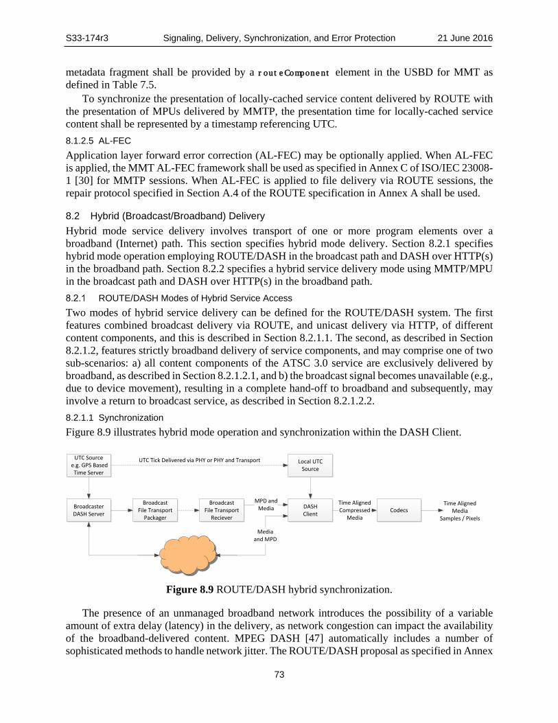
S33-174r3 Signaling, Delivery, Synchronization, and Error Protection 21 June 2016
73
metadata fragment shall be provided by a routeComponent element in the USBD for MMT as defined in Table 7.5.
To synchronize the presentation of locally-cached service content delivered by ROUTE with the presentation of MPUs delivered by MMTP, the presentation time for locally-cached service content shall be represented by a timestamp referencing UTC. 8.1.2.5 AL-FEC Application layer forward error correction (AL-FEC) may be optionally applied. When AL-FEC is applied, the MMT AL-FEC framework shall be used as specified in Annex C of ISO/IEC 23008-1 [30] for MMTP sessions. When AL-FEC is applied to file delivery via ROUTE sessions, the repair protocol specified in Section A.4 of the ROUTE specification in Annex A shall be used.
8.2 Hybrid (Broadcast/Broadband) Delivery Hybrid mode service delivery involves transport of one or more program elements over a broadband (Internet) path. This section specifies hybrid mode delivery. Section 8.2.1 specifies hybrid mode operation employing ROUTE/DASH in the broadcast path and DASH over HTTP(s) in the broadband path. Section 8.2.2 specifies a hybrid service delivery mode using MMTP/MPU in the broadcast path and DASH over HTTP(s) in the broadband path.
ROUTE/DASH Modes of Hybrid Service Access Two modes of hybrid service delivery can be defined for the ROUTE/DASH system. The first features combined broadcast delivery via ROUTE, and unicast delivery via HTTP, of different content components, and this is described in Section 8.2.1.1. The second, as described in Section 8.2.1.2, features strictly broadband delivery of service components, and may comprise one of two sub-scenarios: a) all content components of the ATSC 3.0 service are exclusively delivered by broadband, as described in Section 8.2.1.2.1, and b) the broadcast signal becomes unavailable (e.g., due to device movement), resulting in a complete hand-off to broadband and subsequently, may involve a return to broadcast service, as described in Section 8.2.1.2.2. 8.2.1.1 Synchronization Figure 8.9 illustrates hybrid mode operation and synchronization within the DASH Client.
DASHClient
BroadcastFile Transport
Reciever
MPD and Media
Time AlignedCompressed
MediaCodecsBroadcaster
DASH Server
UTC Source e.g. GPS Based
Time Server
BroadcastFile Transport
Packager
Local UTCSource
UTC Tick Delivered via PHY or PHY and Transport
Time AlignedMedia
Samples / Pixels
Media and MPD
Figure 8.9 ROUTE/DASH hybrid synchronization.
The presence of an unmanaged broadband network introduces the possibility of a variable amount of extra delay (latency) in the delivery, as network congestion can impact the availability of the broadband-delivered content. MPEG DASH [47] automatically includes a number of sophisticated methods to handle network jitter. The ROUTE/DASH proposal as specified in Annex

S33-174r3 Signaling, Delivery, Synchronization, and Error Protection 21 June 2016
74
A allows the broadcaster to employ techniques specified in the DASH-IF [8] profile of MPEG DASH [47] to optimize the user experience in the hybrid delivery case:
• A device with an excellent Internet connection may be able to get media data via broadband at least as fast as via broadcast. However, the broadcaster can ensure that broadband-delivered service components are made available to the broadcaster’s broadband server well ahead of the broadcast-delivered components of the service to accommodate slower connections. This is especially easy for pre-produced (non-live) content and can be achieved for live content.
• MPEG DASH [47] specifies an optional attribute called @availabilityTimeOffset that can be associated with a particular delivery network via the parameter BaseURL. This allows the broadcaster to notify the DASH client in the receiver that it is OK to request broadband-delivered content earlier than the availability time of the broadcast-delivered stream. Since the likely usage scenario for broadband delivery of service components is audio, interactivity, captions, or the like (and not video), the buffering requirements at the receiver are not expected to be burdensome.
• The MPD for an ATSC 3.0 service shall contain @availabilityTimeOffset when broadband available content is available prior to broadcast of EXT_TIME header (SCT) for time aligned broadcast delivered media
Buffering is handled slightly differently for the different delivery modes. DASH Segments for unicast broadband components are requested by receivers in advance of the time they are needed, as indicated by the timeline set by the DASH MPD, and they are buffered until their presentation times. The receivers control delivery timing and buffering. Segments for broadcast components are delivered from the broadcast source according to the buffer model, which ensures that receivers get the Segments soon enough to avoid decoder stall, and not so early that buffers could overflow. The broadcast source uses the DASH MPD timeline to determine the appropriate delivery timing. 8.2.1.2 Broadband DASH-only Service Access 8.2.1.2.1 Exclusive Delivery of Service Components via Broadband
In this mode, all content components of the ATSC 3.0 service shall be carried exclusively over broadband – i.e. no content components are delivered via broadcast. Such implementation is indicated by Service Layer Signaling (SLS) as specified in Section 7, specifically, by the combination of the unified MPD fragment and the userServiceDescription.deliveryMethod element of the User Service Bundle Description fragment. In this case, only the child element unicastAppService shall be present under the deliveryMethod element (i.e. broadcastAppService is absent). 8.2.1.2.2 Hand-off from Broadcast to Broadband Service Access
This operational scenario involves the mobile ATSC 3.0 receiver, which due to user mobility, may move temporarily outside broadcast coverage and whereby only fallback service reception via broadband is possible. Similar to the scenario described in Section 8.2.1.2.1, support for such hand-off between different access modes may be indicated by the MPD fragment in SLS. In this case, as defined by the SLS protocols in Section 7, the userServiceDescription.deliveryMethod element in the User Service Bundle Description fragment shall contain both the child elements broadcastAppService and unicastAppService, which represent the broadcast and broadband delivered components, respectively, of the named service. Furthermore, these broadcast and unicast delivered components may be substituted for one another in the case of hand-off from broadcast to broadband service access, or vice versa, from broadband to broadcast service access.

S33-174r3 Signaling, Delivery, Synchronization, and Error Protection 21 June 2016
75
MMTP/MPU Modes of Hybrid Service Access
8.2.2.1 Introduction The overall hybrid streaming over broadcast and broadband delivery architecture for both the transmission system and the receiver system is shown in Figure 8.10. All the components of the system are locked to UTC for synchronization.
For the broadcast network, media data are encapsulated into MPUs, which are packetized into MMTP packets as specified in Section 8.1.2 of this document. For the broadband network, media data are encapsulated into DASH Segments. DASH Segments are delivered by an HTTP session through the network interface by a regular HTTP server while a DASH MPD is delivered via the broadcast network. The URI reference for a DASH MPD shall be provided by an atsc:broadbandComponent element in the USBD for MMT as defined in Table 7.5.
For the client it is assumed that the MMTP packets delivered through the broadcast network are de-packetized and the media data are decoded by the appropriate media decoders, and that the DASH Segments are delivered through the broadband network. To synchronize the presentation of a DASH Segment delivered via the broadband network with an MPU delivered via the broadcast network, the presentation time of the DASH Segment is represented by a timestamp referencing UTC.
Signaling Message
MMTPPacketization
HTTPServer
Modulation
Signaling Packets
MMTP/UDP/IPPacketsMPUs
DASH Segments
Network Interface
HTTP/TCP/IPPackets
Network Interface
DASH MPD
Depacketiz-ation of
Signaling messages
MMTPDepacket-
ization
DASHClient
HTTPClient
Media Decoder(s)
MPD
Rendering
Engine
UTC
UTC
Demodulation
Figure 8.10 Conceptual hybrid service architecture.
8.2.2.2 Constraints on DASH DASH Segments as specified in the DASH-IF [8] profile of MPEG DASH [47] shall be used as the encapsulation format for broadband streaming media delivery.

S33-174r3 Signaling, Delivery, Synchronization, and Error Protection 21 June 2016
76
8.2.2.3 Synchronization The synchronization of streaming media shall use timestamps referencing UTC. The MPU_timestamp_descriptor as defined in subclause 9.5.2 of ISO/IEC 23008-1 [30] shall be used to represent the presentation time of the first media sample in presentation order in each MPU.
The presentation timing for DASH Segments delivered through HTTP shall be based on the DASH Media Presentation timeline referencing UTC. The DASH MPD shall provide attributes for calculating the presentation time of the first sample in presentation order.
Frame-level media timing of both MPUs and DASH Segments shall be as per the DASH-IF [8] profile of ISO BMFF semantics [46]. 8.2.2.4 Acquisition Acquisition of broadcast MPU streaming shall be as specified as in Section 8.1.2. Acquisition of broadband content accessed through HTTP shall be as specified as in Section 8.2.1.2. 8.2.2.5 Broadband-Only Service (Signaled by Broadcast) 8.2.2.5.1 Zero Components Delivered by Broadcast
Media data is encapsulated into DASH Segments. DASH MPDs are delivered via the broadcast network by a signaling message and DASH Segments are delivered via the broadband network by an HTTP session through the network interface by a regular HTTP server.
8.3 File Repair Procedure As described in Section 7.1.7, the file repair procedure is an HTTP request/response transaction whereby a receiver, unable to acquire the entire object delivered by ROUTE, can request and obtain the missing data via broadband from a file repair server. File repair is typically used to ensure reliable recovery of NRT content (app-based enhancements or data services). NRT content need not be consumed in real-time, and therefore the delay incurred by the request and return of missing data over broadband, after broadcast delivery has ended, is usually acceptable to the application making use of that data.
Under the assumption that the object delivered by ROUTE/broadcast was not completely received, usage of the file repair procedure, if desired by the receiver, will depend on the implementation method of the ROUTE protocol for NRT content delivery, as well as whether the receiver is AL-FEC enabled, as follows:
a) Broadcast delivery of the file object does not employ AL-FEC. This implies that only the ROUTE source protocol is implemented for the object delivery (i.e., the repair protocol is not implemented). In this scenario, the receiver need not be AL-FEC capable to perform file repair. It can request, from the file repair server, byte range(s) corresponding to the byte position(s) of the missing data in the delivery object.
b) Broadcast delivery of the file object does not employ AL-FEC on the ROUTE source protocol, but the repair protocol, which employ AL-FEC, is also implemented. In this scenario, a receiver which is not AL-FEC capable can perform file repair in exactly the same manner as described in scenario (a) above. For AL-FEC capable receivers, it is expected to first employ AL-FEC decoding to determine whether the file can be fully recovered from the FEC symbols sent on the repair protocol. If file recovery is still unsuccessful, the AL-FEC capable receiver may request byte range(s) corresponding to the position(s) of a subset of the missing source symbols in the delivery object. Such subset represents the number of source symbols required by the receiver to ensure guaranteed object recovery, as a property of the AL-FEC scheme in use.

S33-174r3 Signaling, Delivery, Synchronization, and Error Protection 21 June 2016
77
c) Broadcast delivery of the file object employs AL-FEC, and only the ROUTE repair protocol is implemented by the sender. This scenario is likely to only occur if the broadcaster believes that all targeted receivers are AL-FEC capable, since AL-FEC incapable receivers is unable to download the content sent by the repair protocol. AL-FEC capable receivers is expected to operate in the same manner as in scenario (b). In other words, it initially employs AL-FEC decoding to recover the delivery object. If object recovery via AL-FEC decoding is unsuccessful, the receiver may perform file repair to request missing data in the form of source symbols.
As described in the above scenarios, the file repair mechanism performed by the receiver is expected to differ depending on whether it is AL-FEC capable. In addition, as indicated in the above scenarios, the implementation of ROUTE should judiciously take into account the assumption by the broadcaster on AL-FEC capability of its targeted receiver population.
File Repair for Receivers that are not AL-FEC Capable Assuming that the delivery object was not completely received during broadcast delivery via the ROUTE source protocol, a high-level summary of the file repair procedure performed by a receiver that is not AL-FEC capable is provided below. The description applies to both scenarios (a) and (b) above for a receiver that is not AL-FEC capable, as well as to scenario (a) only for a receiver that is AL-FEC capable. In performing the file repair procedure, the receiver shall utilize the APD fragment (as previously described in Section 7.1.7) as well as the EFDT element in the S-TSID fragment (see Annex A, Section A.3.3.2.2), each of which are associated with the source flow carrying the delivery object of concern. The APD and the EFDT provide information on the location of the file repair server, and temporal parameters that govern when the file repair procedure should begin. The sequence of events are as follows:
1) The receiver determines that broadcast file delivery has ended; 2) It identifies missing data from the broadcast reception as the corresponding byte range(s)
in the delivery object; 3) It calculates a random back-off time and selects a repair server from a list provided in the
EFDT; 4) The receiver sends a HTTP repair request message for the missing data to the selected
repair server at the computed time; 5) File repair server returns the requested byte ranges; 6) The file of interest is recovered, and forwarded to a cache or a service application. The means by which the receiver may select and determine the location of a file repair server,
and the deadline by which the receiver can expect the requested data to be returned by the repair server, are described in Section 8.3.3.
File Repair for Receivers that are AL-FEC capable Here, similar to Section 8.3.1, it is assumed that the delivery object was not completely received during broadcast delivery via the ROUTE protocol, a high-level summary of the file repair procedure performed by a receiver that is AL-FEC capable is provided below. The description applies to both scenarios (b) and (c) above). Also similar to Section 8.3.1, in performing the file repair procedure, the receiver shall utilize the APD fragment and the EFDT element in the S-TSID fragment to provide information on the location of the file repair server, and temporal parameters that govern when the file repair procedure should begin. The main difference between the scenarios in Sections 8.3.1 and 8.3.2 pertains to steps 2 and 4. Here, because the receiver is AL-FEC capable, it will determine the missing data as FEC symbol(s), and the byte range(s) in the HTTP request

S33-174r3 Signaling, Delivery, Synchronization, and Error Protection 21 June 2016
78
represents the mapping from the desired source symbol(s) to its(their) locations in the delivery object. The sequence of events are as follows:
1) The receiver determines that broadcast file delivery has ended; 2) It identifies missing data from the broadcast reception as FEC symbol(s), and converts
that to one or more byte ranges corresponding to the positions of the desired source symbol(s) in the delivery object;
3) It calculates a random back-off time and selects a repair server from a list provided in the EFDT;
4) The receiver sends a HTTP repair request message for the missing data, as byte range(s) of source symbols(s), to the selected repair server at the computed time;
5) File repair server returns the requested byte ranges; 6) The file of interest is recovered, and forwarded to a cache or a service application. Repair Server Location and Response Deadline
The location(s) of the one or more file repair servers, in the form of HTTP(s) URLs, which the receiver may contact to request repair data are provided by the Alternate-Content-Location-1 and Alternate-Content-Location-2 child elements of the EFDT element. At least one Alternate-Content-Location-1 element in the EFDT shall be present, and if more than one such element is present, the receiver can choose any of them to use. Alternate-Content-Location-2 if present, represents the one or more file repair servers as back-up to the main repair server(s) specified by Alternate-Content-Location-1. If more than one instance of Alternate-Content-Location-2 is present and necessary for use as back-up repair server, the receiver can choose to use any of them. File repair server URL selection by the receiver, in decreasing priority is:
• byte-range based repair servers included as Alternate-Content-Location-1 • byte-range based repair servers included as Alternate-Content-Location-2 When present, the Base-URL-1 and Base-URL-2 elements provide base URLs against which to
resolve a relative reference included in any Alternate-Content-Location-1 or Alternate-Content-Location-2 element, respectively.
When present, the Availability-Time attribute indicates the latest wall-clock time, according to the UTC time standard, that the UE should expect that, if reachable and functioning, the contacted file repair server will return the requested repair data.

S33-174r3 Signaling, Delivery, Synchronization, and Error Protection, Annex A 21 June 2016
79
Annex A: ROUTE
A.1 OVERVIEW OF ROUTE
A.1.1 General The Real-time Object delivery over Unidirectional Transport (ROUTE) protocol is split in two major components:
• The source protocol for delivery of objects or flows/collection of objects (see Section A.3).
• The repair protocol for flexibly protecting delivery objects or bundles of delivery objects that are delivered through the source protocol (see Section A.4). The association between delivery objects delivered in the source protocol and the repair protocol is also provided in Section A.4.
The source protocol is independent of the repair protocol, i.e. the source protocol may be deployed without the ROUTE repair protocol. Repair may be added only for certain deployment scenarios, for example only for mobile reception, only in certain geographical areas, only for certain service, etc.
A.1.2 Source Protocol The ROUTE source protocol is aligned with FLUTE as defined in RFC 6726 [26] as well as the extensions defined in MBMS [9], but also makes use of some principles of FCAST as defined in RFC 6968 [45], for example, object metadata and the object content may be sent together in a compound object.
In addition to the basic FLUTE protocol, certain optimizations and restrictions are added that enable optimized support for real-time delivery of media data; hence, the name of the protocol. Among others, the source ROUTE protocol enables or enhances the following functionalities:
• Real-time delivery of object-based media data • Flexible packetization, including enabling media-aware packetization as well as transport
aware packetization of delivery objects • Independence of files and delivery objects, i.e. a delivery object may be a part of a file or
may be a group of files
A.1.3 Repair Protocol The ROUTE repair protocol is FEC based and enabled as an additional layer between the transport layer (e.g., UDP) and the object delivery layer protocol. The FEC reuses concepts of FEC Framework defined in RFC 6363 [44], but in contrast to the FEC Framework in RFC 6363 [44] the ROUTE repair protocol does not protect packets, but instead it protects delivery objects as delivered in the source protocol. In addition, as an extension to FLUTE, it supports the protection of multiple objects in one source block which is in alignment with the FEC Framework as defined in RFC 6363 [44]. Each FEC source block may consist of parts of a delivery object, as a single delivery object (similar to FLUTE) or multiple delivery objects that are bundled prior to FEC

S33-174r3 Signaling, Delivery, Synchronization, and Error Protection, Annex A 21 June 2016
80
protection. ROUTE FEC makes use of FEC schemes in a similar way as those defined in RFC 5052 [18], and uses the terminology of that document. The FEC scheme defines the FEC encoding and decoding, as well as the protocol fields and procedures used to identify packet payload data in the context of the FEC scheme.
In ROUTE all packets are LCT packets as defined in RFC 5651 [23]. Source and repair packets may be distinguished by:
• Different ROUTE sessions; i.e., they are carried on different IP/UDP port combinations. • Different LCT channels; i.e., they use different TSI values in the LCT header. • The PSI bit in the LCT, if carried in the same LCT channel. This mode of operation is
mostly suitable for FLUTE-compatible deployments.
A.1.4 Features ROUTE defines the following features:
• Source protocol including packet formats, sending behavior and receiving behavior • Repair protocol • Metadata for transport session establishment • Metadata for object flow delivery • Recommendations for DASH configuration and mapping to ROUTE to enable rich and
high-quality linear TV broadcast services. In addition, as an extension to FLUTE, it supports the protection of multiple objects in one source block which is in alignment with the FEC Framework as defined in RFC 6363 [44]
A.1.5 System Architecture The scope of the ROUTE protocol is the reliable transport of delivery objects and associated metadata using LCT packets. This architecture is depicted in Figure A.1.1. In the figure, dotted-line connections illustrate the type of data being conveyed from one functional block to another.
The normative aspects of the ROUTE protocol focus on the following aspects: • The format of the LCT packets that carry the delivery objects. • The reliable transport of the delivery object using a repair protocol based on FEC. • The definition and carriage of object metadata along with the delivery objects to enable
the interface between the delivery object cache and the application. • The ROUTE and LCT channel description to establish the reception of objects along with
their metadata. • The normative aspects (formats, semantics) of auxiliary information to be delivered along
with the packets to optimize the performance for specific applications; e.g., real-time delivery. The objects are made available to the application through a Delivery Object Cache.

S33-174r3 Signaling, Delivery, Synchronization, and Error Protection, Annex A 21 June 2016
81
ROUTE Receiver Model
ROUTE Sender
PacketReceiver
Encoder &DASHer
DASH ClientMedia and DASH Formats
Delivery Object CacheLCT
DASH Media Presentation
Objects & Object metadata
FECdecoder
Objectrecovery
ROUTE & LCT ChannelDescription
Figure A.1.1 Reference receiver architecture model in ROUTE.
Figure A.1.2 shows the basic sender concept. A ROUTE session is established that delivers LCT packets. These packets may carry source objects or FEC repair data. From a top down approach, a source protocol consists of one or more LCT channels, each carrying associated objects along with their metadata. The metadata may be statically delivered in signaling metadata or may be dynamically delivered, either as a compound object in the Entity Mode or as LCT extension headers in packet headers. The packets are carried in ALC using a specific FEC scheme that permits flexible fragmentation of the object at arbitrary byte boundaries. In addition, delivery objects may be FEC protected, either individually or in bundles. In either case, the bundled object is encoded and only the repair symbols are delivered, whereas the source symbols are not delivered. In combination with the source packets, this permits the recovery of delivery object bundles. Note that one or more repair flows may be generated, each with different characteristics, for example to support different latency requirements, different protection requirements, etc.
The flexible FEC concept also permits different protection for different source streams, for example to differentiate the level of protection for the base layer and the enhancement layer when a scalable video codec is in use.

S33-174r3 Signaling, Delivery, Synchronization, and Error Protection, Annex A 21 June 2016
82
Figure A.1.2 Sender operation of ROUTE protocol.
The architecture supports different protection and delivery schemes of the source data. It also supports all existing use cases for NRT delivery, as it can be deployed in a backwards-compatible mode.
A.2 DATA MODEL AND SESSION INITIATION
A.2.1 Data Model Each ROUTE session shall be associated with an IP address/port combination. Each ROUTE session shall constitute one or more LCT channels. LCT channels are a subset of a ROUTE session. For media delivery, an LCT channel would typically carry a media component, for example a DASH Representation. From the perspective of broadcast delivery of DASH formats, the ROUTE session can be considered as the multiplex of LCT channels that carry constituent media components of one or more DASH Media Presentations. Within each transport session, one or more objects are carried, typically objects that are related, e.g. DASH Segments associated to one Representation. Along with each object, metadata properties are delivered such that the objects can be used in application services which may include, but are not limited to, DASH Media Presentations, HTML-5 Presentations, or any other object-consuming application.
A.2.2 ROUTE Session ROUTE sessions may be temporarily bounded or unbounded.
A ROUTE session contains one or more LCT channels. Each transport session shall be uniquely identified by a unique Transport Session Identifier (TSI) value in the LCT header. The
UDP/IP + Port (ROUTE Session)
Source ALC(RFC 5775: Asynchronous Layered Coding Protocol
Instantiation)
LCT(RFC 5651: Layered Coding Transport Building Block)
LCT Header Extensions
for DMD delivery
FEC Scheme Raptor(Q)
(RFC6330)
Repair ALC(RFC 5775: Asynchronous Layered Coding Protocol
Instantiation)
LCT(RFC 5651: Layered Coding Transport Building Block)
DO 1.1
DO 1.2
DO 1.3
Optional Object Bundling
LCT Session 1
DO 2.1
DO 2.2
DO.2.3
LCT Session 2Static
Metadata 2Static
Metadata
DMD
DMD
DMD
DMD
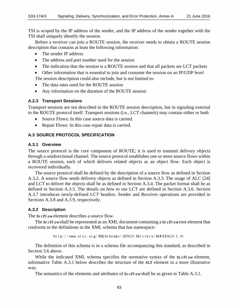
S33-174r3 Signaling, Delivery, Synchronization, and Error Protection, Annex A 21 June 2016
83
TSI is scoped by the IP address of the sender, and the IP address of the sender together with the TSI shall uniquely identify the session.
Before a receiver can join a ROUTE session, the receiver needs to obtain a ROUTE session description that contains at least the following information:
• The sender IP address • The address and port number used for the session • The indication that the session is a ROUTE session and that all packets are LCT packets • Other information that is essential to join and consume the session on an IP/UDP level The session description could also include, but is not limited to: • The data rates used for the ROUTE session • Any information on the duration of the ROUTE session
A.2.3 Transport Sessions Transport sessions are not described in the ROUTE session description, but in signaling external to the ROUTE protocol itself. Transport sessions (i.e., LCT channels) may contain either or both
• Source Flows: In this case source data is carried. • Repair Flows: In this case repair data is carried.
A.3 SOURCE PROTOCOL SPECIFICATION
A.3.1 Overview The source protocol is the core component of ROUTE; it is used to transmit delivery objects through a unidirectional channel. The source protocol establishes one or more source flows within a ROUTE session, each of which delivers related objects as an object flow. Each object is recovered individually.
The source protocol shall be defined by the description of a source flow as defined in Section A.3.2. A source flow sends delivery objects as defined in Section A.3.3. The usage of ALC [24] and LCT to deliver the objects shall be as defined in Section A.3.4. The packet format shall be as defined in Section A.3.5. The details on how to use LCT are defined in Section A.3.6. Section A.3.7 introduces newly-defined LCT headers. Sender and Receiver operations are provided in Sections A.3.8 and A.3.9, respectively.
A.3.2 Description The SrcFlow element describes a source flow.
The SrcFlow shall be represented as an XML document containing a SrcFlow root element that conforms to the definitions in the XML schema that has namespace:
http://www.atsc.org/XMLSchemas/ATSC3/Delivery/ROUTESLS/1.0/
The definition of this schema is in a schema file accompanying this standard, as described in Section 3.6 above.
While the indicated XML schema specifies the normative syntax of the SrcFlow element, informative Table A.3.1 below describes the structure of the SLT element in a more illustrative way.
The semantics of the elements and attributes of SrcFlow shall be as given in Table A.3.1.

S33-174r3 Signaling, Delivery, Synchronization, and Error Protection, Annex A 21 June 2016
84
Table A.3.1 Semantics of SrcFlow Element Element or Attribute Name Use Data Type Description SrcFlow srcFlowType Source flow carried in the LCT channel. @rt 0..1 boolean Indication of whether the source flow conveys real-time
content. @minBuffSize 0..1 unsignedInt The minimum number of kilobytes required in the
receiver transport buffer for the LCT channel. EFDT 0..1 The extended FDT instance. ContentInfo 0..1 string Additional information that can be mapped to the
application service that is carried in this transport session.
Payload 1..N Information on the payload of ROUTE packets carrying the objects of the source flow
@codePoint 0..1 unsignedByte A numerical representation of the combination of values specified for the child elements and attributes of the Payload element.
@formatID 1 unsignedByte The payload format of the delivery object. @frag 0..1 unsignedByte Indication of how the payload of ROUTE packets
carrying the objects of the source flow are fragmented for delivery.
@order 0..1 unsignedByte Indication of how the payload of ROUTE packets carrying the objects of the source flow as DASH Segments are delivered in the order of their generation by the DASH encoder.
@srcFecPayloadID 0..1 unsignedByte Defined values of the Source FEC Payload ID. FECParams 0..1 Parameters of the FEC scheme associated with the
source flow, in the form of FEC Object Transmission Information.
Legend: Note that the conditions only hold without using xlink:href. If linking is used, then all attributes are "optional" and <minOccurs=0> Elements are bold; attributes are non-bold and preceded with an @.
A.3.2.1 Source Flow Semantics
The following text specifies the semantics of the portion of elements and attributes in the SrcFlow fragment represented in Table A.3.1. SrcFlow – A complex element whose subordinate elements and attributes contain information
about each of the one or more Source Flows (as defined in Annex A, Section A.3), within its parent LCT channel.
@rt – A binary flag which shall be used to indicate whether the content component of the ATSC 3.0 service carried by this source flow corresponds to real-time streaming media, or non-real-time content. When set to ”1” or ‘true’, it shall be an indication of real-time content, and if absent, or set to “0” or ‘false’, it shall be an indication of non-real-time content.
@minBufferSize – A 32-bit unsigned integer which shall represent, in kilobytes, the minimum required storage size of the receiver transport buffer, for the parent LCT channel of this Source Flow. This attribute shall only be applicable when @rt = ”1” or ‘true’. If @rt = ”1” or ‘true’ and this attribute is absent, the minimum receiver transport buffer size is unknown.
EFDT – A complex element whose subordinate elements and attributes carry file/object descriptors contained in the Extended FDT (EFDT) element as defined for each of the one or more Source Flows, as defined in Sections A.3.3.2.2 and A.3.3.2.3.

S33-174r3 Signaling, Delivery, Synchronization, and Error Protection, Annex A 21 June 2016
85
ContentInfo – Element whose child elements and attributes shall provide additional information for the content component of the ATSC 3.0 service carried by this Source Flow. The contents of this element is TBD.
Payload – A complex element whose subordinate elements and attributes contain information about each type of payload as mapped to the corresponding delivery object carried by ROUTE packets of this Source Flow.
@codePOint – An 8-bit unsigned byte value which shall represent a numerical “shorthand” or “alias” for the specific combination of values specified for the child elements and attributes of the parent Payload element. The value of this attribute shall be identical to the Codepoint (CP) field in the LCT header.
@formatID – An 8-bit unsigned byte value which shall represent the payload format of the delivery object, and which shall be encoded according to the DeliveryObjectFormatID values as specified in Table A.3.2.
@frag – An 8-bit unsigned byte value which shall indicate how the payload of ROUTE packets carrying the objects of the source flow are fragmented for delivery. The following values are currently defined: 0: arbitrary. This value shall mean that the payload of this ROUTE packet carries a contiguous
portion of the delivery object whose fragmentation occurs at arbitrary byte boundaries. 1: application specific (sample based). This value shall mean that the payload of this ROUTE
packet carries media data in the form of one or more complete samples, where the term “sample” is as defined in ISO/IEC 14496-12 [46]. Its usage shall pertain to the MDE mode as described in Sec. 8.1.1.5.2, whereby the packet strictly carries an MDE data block comprising samples stored in the ‘mdat’ box.
2: application specific (a collection of boxes). This value shall mean that the payload of this ROUTE packet contains the entire data content of one or more boxes, where term “box” is as defined in ISO/IEC 14496-12 [46]. Its usage shall pertain to the MDE mode as described in Sec. 8.1.1.5.2, whereby each packet carries the portion of an MDE data block starting with RAP, and strictly comprising boxes which contain metadata (e.g. styp, sidx, moof and their contained (subordinate) boxes).
3-127: reserved for future use 128-255: reserved for proprietary use The default value value of this attribute is “0”.
@srcFecPayloadID – An 8-bit unsigned byte value which shall represent the Source FEC Payload ID, and whose value shall convey the following rules: 0: the source FEC payload ID is absent and the entire delivery object is contained in this packet.
In this case, the FECParams child element of Payload shall be absent. 1: the source FEC payload ID is a 32-bit unsigned integer value that expresses the start offset
in the object. Start offset is defined in Section A.3.5 In this case, the FECParams child element of SrcFlow shall be absent.
2: the FECParams child element of SrcFlow defines the Format of the Source FEC Payload ID. FECParams – A complex element whose subordinate elements and attributes contain parameters
of the FEC scheme associated with the parent source flow, in the form of FEC Object Transmission Information (FEC-OTI) as defined in RFC 5052 [15]. These FEC parameters shall apply to the Source FEC Payload ID value as specified in the ROUTE packet header.

S33-174r3 Signaling, Delivery, Synchronization, and Error Protection, Annex A 21 June 2016
86
A.3.3 Delivery Objects
A.3.3.1 Overview
The ROUTE protocol enables delivery of delivery objects to receivers which recover the delivery objects and pass them to the application.
A delivery object is self-contained for the application, typically associated with certain properties, metadata and timing-related information that are of relevance for the application. In some cases the properties are provided in-band along with the object, in other cases the data needs to be delivered out-of-band in a static or dynamic fashion.
This protocol enables delivery of at least the following delivery objects: 1) Complete or partial files described and accompanied by an FDT instance. 2) HTTP Entities (HTTP Entity Header and HTTP Entity Body). 3) Packages of delivery objects. In particular, a type 1 or 2 delivery object may be further differentiated by: • Whether it corresponds to a full file or a byte range of a file, along with FDT instance. • Whether it represents timed or non-timed delivery. If timed, certain real-time and buffer
restrictions apply and specific extension headers may be used. • Usage of dynamic and/or static metadata to describe delivery object properties. • Delivery of specific data structures, especially ISO BMFF structures. In this case a
media-aware packetization or a general packetization may be applied. The delivery format ID specifies the payload format used in order to provide information to
the applications. Values of DeliveryObjectFormatID shall be as specified in Table A.3.2.
Table A.3.2 Meaning of DeliveryObjectFormatID Values DeliveryObjectFormatID Value Meaning 0 Reserved 1 File Mode as defined in Section A.3.3.2 2 Entity Mode as defined in Section A.3.3.3 3 Package as defined in Section A.3.3.4 ≥ 4 Reserved
A.3.3.2 File Mode
A.3.3.2.1 Background
In the file mode, the delivery object represents a file or a byte range of the file. This mode replicates FLUTE as defined in RFC 6726 [26], but with the ability to send metadata in a static manner as shown in Figure A.3.1.
In FLUTE, FDT instances are delivered in-band and need to be generated and delivered in real-time if objects are generated in real-time at the sender. In contrast to the FDT in RFC 6726 [26], Section 3.4.2 and MBMS [9], Section 7.2.10, the FDT in ROUTE is extended by the use of rules that enable the receiver to generate the File element of the FDT, on-the-fly, by using information in the extended FDT and the LCT header.
The extended FDT together with the LCT packet header may be used to generate the FDT-equivalent descriptions for the delivery object. This avoids the necessity of continuously sending the FDT for real-time objects.
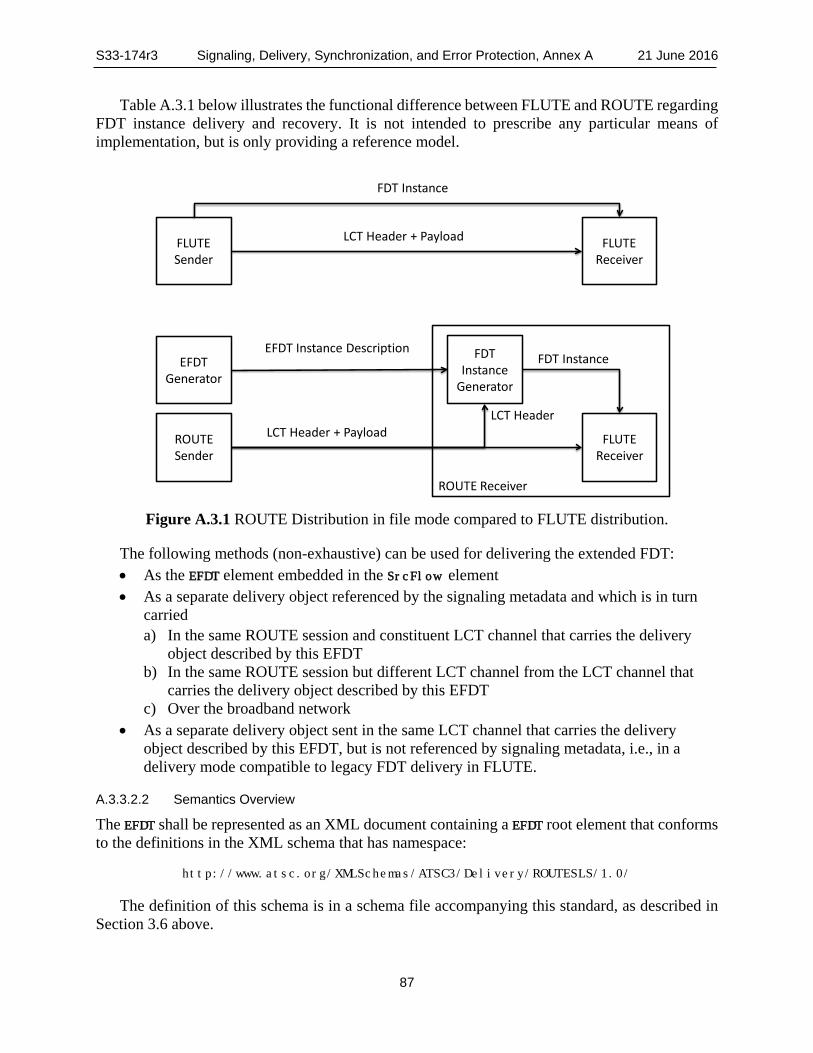
S33-174r3 Signaling, Delivery, Synchronization, and Error Protection, Annex A 21 June 2016
87
Table A.3.1 below illustrates the functional difference between FLUTE and ROUTE regarding FDT instance delivery and recovery. It is not intended to prescribe any particular means of implementation, but is only providing a reference model.
Figure A.3.1 ROUTE Distribution in file mode compared to FLUTE distribution.
The following methods (non-exhaustive) can be used for delivering the extended FDT: • As the EFDT element embedded in the SrcFlow element • As a separate delivery object referenced by the signaling metadata and which is in turn
carried a) In the same ROUTE session and constituent LCT channel that carries the delivery
object described by this EFDT b) In the same ROUTE session but different LCT channel from the LCT channel that
carries the delivery object described by this EFDT c) Over the broadband network
• As a separate delivery object sent in the same LCT channel that carries the delivery object described by this EFDT, but is not referenced by signaling metadata, i.e., in a delivery mode compatible to legacy FDT delivery in FLUTE.
A.3.3.2.2 Semantics Overview
The EFDT shall be represented as an XML document containing a EFDT root element that conforms to the definitions in the XML schema that has namespace:
http://www.atsc.org/XMLSchemas/ATSC3/Delivery/ROUTESLS/1.0/
The definition of this schema is in a schema file accompanying this standard, as described in Section 3.6 above.
ROUTE Receiver
FLUTE Sender
FLUTE Receiver
LCT Header + Payload
FDT Instance
ROUTE Sender
FLUTE Receiver
LCT Header + Payload
EFDT Instance DescriptionEFDT
Generator
FDTInstance
Generator
FDT Instance
LCT Header

S33-174r3 Signaling, Delivery, Synchronization, and Error Protection, Annex A 21 June 2016
88
While the indicated XML schema specifies the normative syntax of the EFDT element, informative Table A.3.3 below describes the structure of the EFDT element in a more illustrative way.
The semantics of the elements and attributes of EFDT shall be as given in Table A.3.3.
Table A.3.3 Extended File Delivery Table Semantics Element or Attribute Name Use Data Type Description EFDT Provides the details of the file delivery data in the form
of the Extended FDT instance which includes nominal FDT instance parameters.
@tsi 0..1 unsignedInt TSI of the LCT channel carrying the referenced EFDT. @idRef 0..1 anyURI Identification of the EFDT in the form of a URI when
the EFDT is delivered in-band with the source flow as a referenced delivery object.
@version 0..1 unsignedInt The version of this Extended FDT instance descriptor. @maxExpiresDelta 0..1 unsignedInt Time interval for use in deriving the expiration time of
the associated EFDT. @maxTransportSize 0..1 unsignedInt The maximum transport size of any object described
by this EFDT. FileTemplate 0..1 string Describes the means to generate the file URL, i.e.
Content-Location attribute of the FDT). FDTParameters 0..1 fdt:FDT-
InstanceType Any parameters allowed in the FLUTE FDT instance.
EFDT – A complex element whose child elements and attributes represent file description entries for the one or more delivery objects carried in the parent Source Flow, in the form of the Extended File Delivery Table (Extended FDT) as defined in Sections A.3.3.2.2 and A.3.3.2.3. If present, this element shall contain the descriptions of the affiliated delivery objects, including i) nominal FLUTE FDT instance parameters as defined in RFC 6726 [26], ii) certain extensions to the FLUTE FDT as defined by 3GPP in MBMS [9], and iii) ATSC-defined extensions to the FLUTE FDT as specified in this document. Presence of this element shall be an indication that the Extended FDT is embedded in the S-TSID. Absence of this element shall be an indication that the Extended FDT is carried as a separate delivery object, with TOI = ‘0’, in the LCT channel of the associated Source Flow. In the latter (referencing) case, the Extended FDT may be updated independently of the signaling metadata.
@tsi – A 32-bit unsigned integer whose value shall represent the TSI (Transport Session Identifier) of the LCT channel carrying the referenced EFDT. @tsi is an ATSC-defined extension of the FLUTE FDT as specified in RFC 6726 [26].
@idRef – A URI whose value shall represent a reference to the identity of the EFDT object when the latter is delivered in-band with the source flow which carries the delivery object referenced by this EFDT. The format of @idRef shall be identical to Content-Location attribute of the EFDT element. @idRef is an ATSC-defined extension of the FLUTE FDT as specified in RFC 6726 [26].
@version – A 32-bit unsigned integer value that shall represent the version of this EFDT element. The version shall be increased by one each time the EFDT element is updated. The received EFDT with the highest version number shall be considered as the currently valid version. @version is an ATSC-defined extension of the FLUTE FDT as specified in RFC 6726 [26].

S33-174r3 Signaling, Delivery, Synchronization, and Error Protection, Annex A 21 June 2016
89
@maxExpiresDelta – A 32-bit unsigned integer value that shall represent a time interval in number of seconds, which when added to the wall-clock time at the receiver when it acquires the first ROUTE packet carrying the object described by this EFDT, shall represent the expiration time of the associated EFDT. If @maxExpiresDelta is not present, the expiration time of the EFDT shall be given by the sum of a) the value of the ERT field in the EXT_TIME LCT header extension in the ROUTE packet and b) the current receiver time when parsing the packet header. See Section A.3.3.2.3.2 on additional rules for deriving the EFDT expiration time. @maxExpiresDelta is an ATSC-defined extension of the FLUTE FDT as specified in RFC 6726 [26].
@maxTransportSize – A 32-bit unsigned integer value that shall represent the maximum transport size in bytes of any delivery object described by this EFDT. This attribute shall be present if it is not present in FEC_OTI.
FileTemplate – A string value, which when present and in conjunction with parameter substitution, shall be used in deriving the file URL, i.e., the Content-Location attribute, for the delivery object described by this EFDT. The mechanism, as further described in Section A.3.3.2.3.2, shall involve substituting the TOI value of the delivery object for the pattern '$TOI$', if present, in the string representation of FileTemplate. By this means, a one-to-one mapping is created between the TOI and the file URL. It also implies that in the event that each delivery object of the source flow is a DASH Media Segment, the Segment number will be equal to the TOI value of the object.
FDTParameters – A data structure which shall comprise one or more file descriptors as specified in the FLUTE FDT [26] and/or certain 3GPP-defined FDT extensions, defined in MBMS [9] which are adopted in this standard as described in Section 8.3.3. These include Cache-Control, Alternate-Content-Location-1, Alternate-Content-Location-2, Base-URL-1 and Base-URL-2, and @availabilityTime.
A.3.3.2.3 EFDT Instance Semantics
A.3.3.2.3.1 General
If the FileTemplate element is absent, the EFDT shall conform to an FDT instance according to RFC 6726 [26], and may include one or more of the following 3GPP-defined FDT extension parameters according to MBMS [9]: Cache-Control, Alternate-Content-Location-1, Alternate-Content-Location-2, Base-URL-1, Base-URL-2, and @availabilityTime. This means that
• At least one File element must be present, and • The @expires attribute must be present.
If a FileTemplate element is present, then the sender shall operate as follows: • The TOI shall be set such that Content-Location can be derived according to Section
A.3.3.2.3.2. • After sending the first packet of a TOI, none of the packets pertaining to this TOI shall be
sent later than as indicated by @maxExpiresDelta. In addition, the EXT_TIME header with Expected Residual Time (ERT) may be used in order to convey more accurate expiry time, if considered useful. If @maxExpiresDelta is not present, then the EXT_TIME header with Expected Residual Time (ERT) shall be used to signal the value of @expires, according to the procedure described below in Sec. A.3.3.2.3.2.

S33-174r3 Signaling, Delivery, Synchronization, and Error Protection, Annex A 21 June 2016
90
If a FileTemplate element is present, an FDT instance is produced at the receiver as follows: • Any data that is contained in the EFDT may be used as is in generating an FDT instance. • The data in the FileTemplate element is used to generate the file URI (equivalent to the
File@Content-Location in the FDT) as documented in Section A.3.3.2.3.2 with the reception of an LCT packet with a specific TOI value.
A.3.3.2.3.2 File Template
If an LCT packet with a new TOI is received for this transport session, then an FDT instance is generated with a new File entry as follows:
• The TOI is used to generate File@Content-Location using the mechanism defined in Section A.3.3.2.3.3.
• All other parameters that are present in the EFDT element are associated to the File attribute.
• Either the EXT_FTI header (per RFC 5775 [24]) or the EXT_TOL header (per Section A.4.2.6.2) shall be used to extract any relevant FEC transport information and map them into the File parameters. Note that in ROUTE the EXT_TOL header does not need to be present as the Transport Object Length (TOL) can be derived from the last packet (indicated with the B flag) as given by the sum of the start offset for that packet (i.e. the value of the FEC Payload Id header) and the packet payload length in bytes. In addition, presence of the File@Transfer-Length parameter in the EFDT would fulfill the role of the EXT_TOL header.
• If present, the @maxExpiresDelta shall be used to generate the value of the @expires attribute. The receiver is expected to add this value to the current time to obtain the value for @expires. If not present, the EXT_TIME header with Expected Residual Time (ERT) shall be used to extract the expiry time of the FDT instance. If both are present, the smaller of the two values should be used as the incremental time interval to be added to the receiver’s current time to generate the effective value for the @Expires. If neither @maxExpiresDelta nor the ERT field of the EXT_TIME is present, then the expiration time of the EFDT is given by the FDT’s @Expires attribute.
A.3.3.2.3.3 Substitution
If the FileTemplate element is present, the value of FileTemplate element may contain the identifiers listed in Table A.3.4.
If no identifier is present, then the FileTemplate shall be a valid URL corresponding identically to the File@Content-Location attribute of the FDT, and the URL is associated to the object with the TOI number in this transport session.
If the $TOI$ is present, then this element is used to generate a one-to-one mapping between the TOI and URL. In the event that each delivery object of the object flow is a DASH Media Segment, the Segment number may be equal to the TOI value.
In each URI, the identifiers from Table A.3.4 shall be replaced by the substitution parameter defined in Table A.3.4. Identifier matching is case-sensitive. If the URI contains unescaped $ symbols which do not enclose a valid identifier then the result of URI formation is undefined. The format of the identifier is also specified in Table A.3.4.
Each identifier may be suffixed, within the enclosing ‘$’ characters following this prototype: %0[width]d

S33-174r3 Signaling, Delivery, Synchronization, and Error Protection, Annex A 21 June 2016
91
The width parameter is an unsigned integer that provides the minimum number of characters to be printed. If the value to be printed is shorter than this number, the result shall be padded with zeroes. The value is not truncated even if the result is larger.
The FileTemplate shall be authored such that the application of the substitution process results in valid URIs.
Strings outside identifiers shall only contain characters that are permitted within URIs according to RFC 3986 [16].
Table A.3.4 Identifiers for File templates $<Identifier>$ Substitution Parameter Format
$$ Is an escape sequence, i.e. "$$" is non-recursively replaced with a single "$"
not applicable
$TOI$ This identifier is substituted with the TOI. The format tag may be present. If no format tag is present, a default format tag with width=1 shall be used.
A.3.3.3 Entity Mode
In the Entity Mode, the delivery object represents an entity as defined in RFC 2616 [13], Section 7. An entity consists of entity-header fields and an entity-body.
This mode reuses the major concepts of FCAST as defined in RFC 6968 [45], but permits delivery of any type of HTTP entity headers including extension headers, etc.
The entity-header field sent along with the file provides all information for the contained complete or partial file. Note that if the header contains a Content-Range entity-header then the delivery object represents a portion of the target file, in the form of a byte range. In addition, this mode also allows for chunked delivery in case the entity-header contains the signaling.
A.3.3.4 Packaging
In this delivery mode, the delivery object consists of a group of files that are packaged for delivery only. If applied, this packaging is only used for the purpose of delivery and the client shall unpack the package and provide each file as an independent object to the application. Packaging is supported by Multipart MIME [12], where objects are packaged into one document for transport. Packaged files shall be delivered using the file mode with Content-Type set to multipart/related.
If a file is delivered in package mode, then the ROUTE receiver must unpack the received delivery object before the constituent files are passed to the application, whereas in regular file mode (not in package mode), the object itself is directly handed to the application, even if it would be a multipart MIME file.
A.3.4 Usage of ALC and LCT The ROUTE source protocol is based on ALC as defined in RFC 5775 [24] with the following details:
• The Layered Coding Transport (LCT) Building Block as defined in RFC 5651 [23] is used with the following constraints: o The Congestion Control Information (CCI) field in the LCT header may be set to 0. o The TSI in the LCT header shall be set equal to the value of the
TransportSession@tsi attribute.

S33-174r3 Signaling, Delivery, Synchronization, and Error Protection, Annex A 21 June 2016
92
o The Code Point in the LCT header shall be used to signal the applied formatting as defined in the signaling metadata.
o The MSB of the PSI shall be set to 1 to indicate a source packet. o In accordance to ALC, a source FEC Payload ID header is used to identify, for FEC
purposes, the encoding symbols of the delivery object, or a portion thereof, carried by the associated ROUTE packet. This information may be sent in several ways: As a simple new null FEC scheme with the following usage:
• The value of the source FEC Payload ID header shall be set to 0, in case the ROUTE packet contains the entire delivery object, or
• The value of the source FEC Payload ID header shall be set as a direct address (start offset) corresponding to the starting byte position of the portion of the object carried in this packet using a 32-bit field.
Existing FEC schemes that are widely deployed • Using the Compact No-Code as defined in RFC 5445 [22]. • In a compatible manner to RFC 6330 [25] where the SBN and ESI defines the
start offset together with the symbol size T. The signaling metadata provides the appropriate parameters to indicate any of the
above modes using the @sourceFecPayloadID attribute and the FECParameters element.
• The LCT Header EXT_TIME extension as defined in RFC 5651 [23] may be used by the sender in the following manner: o The Sender Current Time (SCT), depending on the application, may be used to
occasionally or frequently to signal the sender current time. o The Expected Residual Time (ERT) may be used to indicate the expected remaining
time for transmission of the current object. o The Sender Last Changed (SLC) flag is typically not utilized, but may be used to
indicate addition/removal of Segments. • Additional extension headers may be used to support real-time delivery. Such extension
headers are defined in Section A.3.7. • The LCT channel description information is communicated through signaling metadata. • The ROUTE session description is communicated by external means.
A.3.5 Packet Format The packet format used by ROUTE follows the ALC packet format, i.e. the UDP header followed by the LCT header and the Source FEC Payload ID followed by the packet payload. The LCT header shall be as defined in the LCT building block in RFC 5651 [23]. The Source FEC Payload ID in ROUTE is typically represented by the start_offset field, provided either directly or provided by any FEC scheme. The start_offset field value represents the starting byte position, relative to the first byte of the delivery object, of the subsequent and contiguous portion of the delivery object carried in the present ROUTE packet.
The Congestion Control Information (CCI) field in the LCT header contains the required congestion control information. The packet payload contains data bytes belonging to the delivery object. If more than one object is carried in the session, then the TOI within the LCT header shall be used to identify the object to which the packet payload data pertains.

S33-174r3 Signaling, Delivery, Synchronization, and Error Protection, Annex A 21 June 2016
93
The version number field of the LCT header shall be interpreted as the ROUTE version number field. This version of ROUTE implicitly makes use of version 1 of the LCT building block defined in RFC 5651 [23].
The overall ROUTE packet format shall be as depicted in Figure A.3.2. The packet is an IP packet, either IPv4 or IPv6, and the IP header precedes the UDP header. The ROUTE packet format has no dependencies on the IP version number.
0 1 2 3 0 1 2 3 4 5 6 7 8 9 0 1 2 3 4 5 6 7 8 9 0 1 2 3 4 5 6 7 8 9 0 1 +-+-+-+-+-+-+-+-+-+-+-+-+-+-+-+-+-+-+-+-+-+-+-+-+-+-+-+-+-+-+-+-+ | UDP Header | | | +=+=+=+=+=+=+=+=+=+=+=+=+=+=+=+=+=+=+=+=+=+=+=+=+=+=+=+=+=+=+=+=+ | LCT Header | | | +-+-+-+-+-+-+-+-+-+-+-+-+-+-+-+-+-+-+-+-+-+-+-+-+-+-+-+-+-+-+-+-+ | ROUTE (ALC) Header | | | +-+-+-+-+-+-+-+-+-+-+-+-+-+-+-+-+-+-+-+-+-+-+-+-+-+-+-+-+-+-+-+-+ | Payload Data | | ... | +-+-+-+-+-+-+-+-+-+-+-+-+-+-+-+-+-+-+-+-+-+-+-+-+-+-+-+-+-+-+-+-+
Figure A.3.2 Overall ROUTE packet format.
In some special cases a ROUTE sender may need to produce ROUTE packets that do not contain any payload. This may be required, for example, to signal the end of a session or to convey congestion control information. These data-less packets do not contain ROUTE Header or Payload Data, but only the LCT header fields. The total datagram length, conveyed by outer protocol headers (e.g., the IP or UDP header), enables receivers to detect the absence of the ROUTE (ALC) header and payload.
A.3.6 LCT Building Block The LCT packet header fields shall be used as defined by the LCT building block in RFC 5651 [23]. The semantics and usage of the following LCT header fields shall be further constrained in ROUTE as follows: Version number (V) – This 4-bit field indicates the protocol version number. The version number
for this specification is ‘0001’. Protocol-Specific Indication (PSI) – This 2-bit field indicates whether the current packet is a
source packet or an FEC repair packet. As the ROUTE source protocol only delivers source packets, this field shall be set to ‘10’.
Congestion Control flag (C) field – This 2-bit field, as defined in RFC 5651 [23], shall be set to ‘00’.
Transport Session Identifier flag (S) – This 1-bit field shall be set to ‘1’ to indicate a 32-bit word in the TSI field.
Transport Object Identifier flag (O) – This 2-bit field shall be set to ‘01’ to indicate the number of full 32-bit words in the TOI field.
Half-word flag (H) – This 1-bit field shall be set to ‘0’ to indicate that no half-word field sizes are used.

S33-174r3 Signaling, Delivery, Synchronization, and Error Protection, Annex A 21 June 2016
94
Transport Session Identifier (TSI) – This 32-field shall identify the Transport Session in ROUTE. The context of the Transport Session is provided by signaling metadata. The TSI field is constrained to a length of 32 bits because the Transport Session Identifier flag (S) must be set to ‘1’ and the Half-word flag (H) must be set to ‘0’.
Transport Object Identifier (TOI) – This 32-bit field shall identify the object within this session to which the payload of the current packet belongs. The mapping of the TOI field to the object is provided by the Extended FDT. The TOI field is constrained to a length of 32 bits because the Transport Object Identifier flag (O) must be set to ‘01’ and the Half-word flag (H) must be set to ‘0’.
Codepoint (CP) – This 8-bit field is used to indicate the type of the payload that is carried by this packet. Depending on the type of the payload, additional payload header may be added to prefix the payload data. The main changes that ROUTE introduces to the usage of the LCT building block are the
following: • ROUTE limits the usage of the LCT building block to a single channel per session.
Congestion control is thus sender-driven in ROUTE. • The functionality of receiver-driven layered multicast may still be offered by the
application, allowing the receiver application to select the appropriate delivery session based on the bandwidth requirement of that session.
A.3.7 Extension Headers
A.3.7.1 Introduction
For proper operation of the protocol in different circumstances, LCT extension headers are defined that support the operation of the ROUTE protocol for different purposes.
A.3.7.2 EXT_ROUTE_PRESENTATION_TIME Header
A ROUTE presentation time header may be added to an LCT packet. ROUTE applications may use the EXT_ROUTE_PRESENTATION_TIME Header to deliver time-related information as shown in Figure A.3.3. Header Extention Type (HET) value 66 has been registered with IANA for this header. If present, the EXT_ROUTE_PRESENTATION_TIME Header expresses the full 64-bit NTP timestamp value. The value must always be greater than the SCT.
0 1 2 3 0 1 2 3 4 5 6 7 8 9 0 1 2 3 4 5 6 7 8 9 0 1 2 3 4 5 6 7 8 9 0 1 +-+-+-+-+-+-+-+-+-+-+-+-+-+-+-+-+-+-+-+-+-+-+-+-+-+-+-+-+-+-+-+-+ | HET = 66 | HEL | reserved | +-+-+-+-+-+-+-+-+-+-+-+-+-+-+-+-+-+-+-+-+-+-+-+-+-+-+-+-+-+-+-+-+ | NTP timestamp, most significant word | +-+-+-+-+-+-+-+-+-+-+-+-+-+-+-+-+-+-+-+-+-+-+-+-+-+-+-+-+-+-+-+-+ | NTP timestamp, least significant word | +-+-+-+-+-+-+-+-+-+-+-+-+-+-+-+-+-+-+-+-+-+-+-+-+-+-+-+-+-+-+-+-+
Figure A.3.3 12-byte EXT_ROUTE_PRESENTATION_TIME header.
A.3.7.3 EXT_TIME Header
In addition to EXT_ROUTE_PRESENTATION_TIME, the EXT_TIME header as defined in RFC 5651 [23] may be used, and SCT-High and SCT-Low flags may be set.

S33-174r3 Signaling, Delivery, Synchronization, and Error Protection, Annex A 21 June 2016
95
A.3.8 Basic ROUTE Sender Operation The following description of the ROUTE sender operation on mapping of the delivery object to the ROUTE packet payloads logistics represents an extension of RFC 5445 [22], which in turn inherits the context, language, declarations and restrictions of the FEC building block in RFC 5052 [18]. The data carried in the payload of a given ROUTE packet constitute a contiguous portion of the delivery object, and the ROUTE source delivery can be considered as a special case of the use of the Compact No-Code Scheme according to Sections 3.4.1 and 3.4.2 of RFC 5445 [22], in which the encoding symbol size is exactly one byte.
In the basic operation, it is assumed that: • A delivery object is fully available at the ROUTE sender • T > 0 represents the Transfer-Length of the object in bytes • The Source FEC Payload ID comprises the start_offset field The maximum transfer unit of the first data packet is known as Y. The transfer unit is
determined either by knowledge of underlying transport block sizes or by other constraints. In case Y is greater than or equal to T, this is the only packet for this delivery object. Therefore, the Codepoint may be set indicating a packet header size of 0. The entire delivery object is then carried as the payload of the packet.
If Y is smaller than T, then the data carried in the payload of a packet consists of a contiguous portion of the object. For any arbitrary X and any arbitrary Y > 0 as long as X + Y is at most T, a ROUTE packet may be generated. In this case the following shall hold:
1) The data carried in the payload of a packet shall consist of a contiguous portion of the object starting from the beginning of byte X through the beginning of byte X + Y.
2) The start_offset field in the ROUTE packet header shall be set to X and the payload data shall be added into the packet to send.
3) If • X + Y is identical to T, the payload header flag B shall be set to "1". else • The payload header flag B shall be set to "0".
The order of packet delivery is arbitrary, but in the absence of other constraints delivery with increasing start_offset value is recommended. Certain applications may require a strict sending order with increasing start_offset value for each subsequent ROUTE packet.
In other cases, the transfer length may be unknown prior to sending earlier pieces of the data, and only a maximum transfer length is known as signaled in the EFDT parameter @route:maxTransportSize. In this case, T may be determined later. However, this does not affect the sending process above. Additional packets may be sent following the above rules 1 to 3. In this case the B flag shall only be set to ‘1’ for the payload that contains the last portion of the object.
A.3.9 Basic ROUTE Receiver Operation
A.3.9.1 Overview
Figure A.3.4 illustrates the basic receiver operation. The receiver receives packets and filters these packets accordingly. From the ROUTE session and each contained LCT channel it regenerates delivery objects from the ROUTE session and each contained LCT channel. The delivery objects are in turn passed to the appropriate handler for further data processing.

S33-174r3 Signaling, Delivery, Synchronization, and Error Protection, Annex A 21 June 2016
96
The basic receiver information is provided below. In addition, the treatment in case of different received objects is described in this section.
P1.1.0
Delivery Object
Recovery
P1.1.1000
Delivery Object
Processing
Delivery Session carrying Transport Sessions Delivery Objects
Signaling Metadata
Application/DASH player
API
P2.1.0
P2.1.0 P2.1.2000 P2.1.4000
Figure A.3.4 Receiver operation.
A.3.9.2 Basic Delivery Object Recovery
Signaling metadata contains information that describes the carried object flows. Upon receipt of each payload, the receiver proceeds with the following steps in the order listed.
1) The ROUTE receiver is expected to parse the LCT and ROUTE (ALC) header to verify that it is a valid header. If it is not valid, then the payload shall be discarded without further processing.
2) The ROUTE receiver is expected to assert that the TSI and the CodePoint represent valid operation points in the signaling metadata, i.e. the signaling contains a matching entry to the TSI value provided in the packet header, as well as for this TSI, the signaling contains the attribute PayloadFormat@codePoint whose value is identical to the CodePoint field in the LCT header.
3) The ROUTE receiver should process the remainder of the payload, including the appropriate interpretation of the other payload header fields, and using the source FEC Payload ID (to determine the start_offset) and the payload data to reconstruct the corresponding object as follows: a) The ROUTE receiver can determine the object associated with the received ROUTE
packet payload via the signaling metadata and the TOI carried in the LCT header. b) Upon receipt of the first ROUTE packet payload for an object, the ROUTE receiver
uses the maxTransportSize attribute of the EFDT to determine the maximum length T' of the object.
c) The ROUTE receiver allocates buffer space for the T' bytes that the object may occupy.
d) The ROUTE receiver also computes the length of the payload, Y, by subtracting the payload header length from the total length of the received payload.
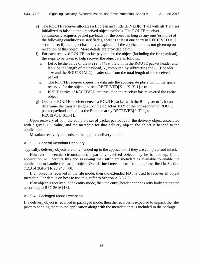
S33-174r3 Signaling, Delivery, Synchronization, and Error Protection, Annex A 21 June 2016
97
e) The ROUTE receiver allocates a Boolean array RECEIVED[0..T'-1] with all T entries initialized to false to track received object symbols. The ROUTE receiver continuously acquires packet payloads for the object as long as any one (or more) of the following conditions is satisfied: i) there is at least one entry in RECEIVED still set to false; ii) the object has not yet expired; iii) the application has not given up on reception of this object. More details are provided below.
f) For each received ROUTE packet payload for the object (including the first payload), the steps to be taken to help recover the object are as follows:
i. Let X be the value of the start_offset field in in the ROUTE packet header and let Y be the length of the payload, Y, computed by subtracting the LCT header size and the ROUTE (ALC) header size from the total length of the received packet.
ii. The ROUTE receiver copies the data into the appropriate place within the space reserved for the object and sets RECEIVED[X ... X+Y-1] = true.
iii. If all T entries of RECEIVED are true, then the receiver has recovered the entire object.
g) Once the ROUTE receiver detects a ROUTE packet with the B flag set to 1, it can determine the transfer length T of the object as X+Y of the corresponding ROUTE packet payload and adjust the Boolean array RECEIVED[0..T'-1] to RECEIVED[0..T-1].
Upon recovery of both the complete set of packet payloads for the delivery object associated with a given TOI value, and the metadata for that delivery object, the object is handed to the application.
Metadata recovery depends on the applied delivery mode.
A.3.9.3 General Metadata Recovery
Typically, delivery objects are only handed up to the application if they are complete and intact. However, in certain circumstances a partially received object may be handed up, if the
application API permits this and assuming that sufficient metadata is available to enable the application to handle the partial object. One defined mechanism for this is described in Section 7.2.3 of 3GPP TR 26.946 [40].
If an object is received in the file mode, then the extended FDT is used to recover all object metadata. For details on how to use this, refer to Section A.3.3.2.3.
If an object is received in the entity mode, then the entity header and the entity body are treated according to RFC 2616 [13].
A.3.9.4 Packaged Mode Reception
If a delivery object is received in packaged mode, then the receiver is expected to unpack the files prior to handing them to the application along with the metadata that is included in the package.

S33-174r3 Signaling, Delivery, Synchronization, and Error Protection, Annex A 21 June 2016
98
A.4 REPAIR PROTOCOL SPECIFICATION
A.4.1 Introduction The delivery objects and bundles of delivery objects delivered by the source protocol as described in Section A.3 may be protected with FEC. The base protocol as defined in Section A.3 avoids including any FEC-specific signaling.
In this section an FEC framework is defined that enables FEC protection of individual or bundles of delivery objects when using the source protocol defined in Section A.3.
The FEC framework uses concepts of the FECFRAME work as defined in RFC 6363 [44], as well as the FEC building block, RFC 5052 [18], which is adopted in the existing FLUTE/ALC/LCT specifications.
The FEC design adheres to the following principles: • FEC-related information is provided only where needed. • Receivers not capable of this framework can ignore repair packets. • The FEC is symbol-based with fixed symbol size per protected repair flow. The ALC
protocol and existing FEC schemes are reused. • A FEC repair flow provides protection of delivery objects from one or more source
flows. The FEC-specific components of the FEC framework are: • FEC repair flow declaration including all FEC specific information. • FEC transport object that is the concatenation of a delivery object, padding octets and
size information in order to form a symbol-aligned chunk of data. • FEC super-object that is the concatenation of one or more FEC transport objects in order
to bundle FEC transport objects for FEC protection. • FEC protocol and packet structure. A receiver needs to be able to recover delivery objects from repair packets based on available
FEC information.
A.4.2 FEC Protocol
A.4.2.1 Introduction
This section specifies the protocol elements for the FEC Framework. Four components of the protocol are defined in this document and are described in the following sections:
1) FEC transport object construction 2) FEC super-object construction as the concatenation of FEC transport objects 3) TOI mapping 4) Repair packet generation The operation of the FEC Framework is governed by Repair Flow definition as defined in
Section 0. Figure A.4.1 shows the FEC packet generation based on two delivery objects.
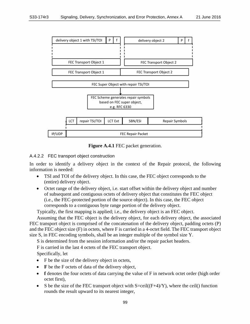
S33-174r3 Signaling, Delivery, Synchronization, and Error Protection, Annex A 21 June 2016
99
delivery object 1 with TSI/TOI delivery object 2P f P f
FEC Transport Object 1 FEC Transport Object 2
FEC Transport Object 1 FEC Transport Object 2
FEC Super Object with repair TSI/TOI
FEC Scheme generates repair symbols based on FEC super object,
e.g. RFC 6330
Repair Symbolsrepair TSI/TOILCT SBN/ESILCT Ext
FEC Repair PacketIP/UDP
Figure A.4.1 FEC packet generation.
A.4.2.2 FEC transport object construction
In order to identify a delivery object in the context of the Repair protocol, the following information is needed:
• TSI and TOI of the delivery object. In this case, the FEC object corresponds to the (entire) delivery object.
• Octet range of the delivery object, i.e. start offset within the delivery object and number of subsequent and contiguous octets of delivery object that constitutes the FEC object (i.e., the FEC-protected portion of the source object). In this case, the FEC object corresponds to a contiguous byte range portion of the delivery object.
Typically, the first mapping is applied; i.e., the delivery object is an FEC object. Assuming that the FEC object is the delivery object, for each delivery object, the associated
FEC transport object is comprised of the concatenation of the delivery object, padding octets (P) and the FEC object size (F) in octets, where F is carried in a 4-octet field. The FEC transport object size S, in FEC encoding symbols, shall be an integer multiple of the symbol size Y.
S is determined from the session information and/or the repair packet headers. F is carried in the last 4 octets of the FEC transport object. Specifically, let • F be the size of the delivery object in octets, • F be the F octets of data of the delivery object, • f denotes the four octets of data carrying the value of F in network octet order (high order
octet first), • S be the size of the FEC transport object with S=ceil((F+4)/Y), where the ceil() function
rounds the result upward to its nearest integer,
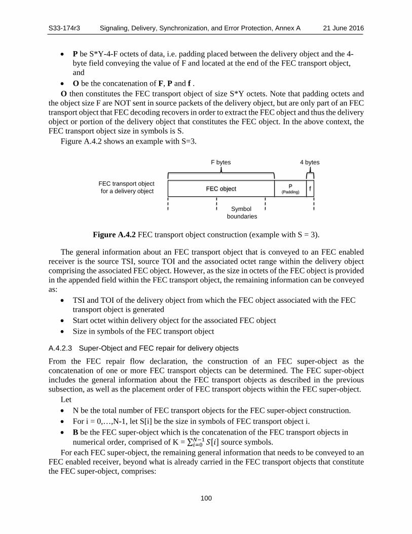
S33-174r3 Signaling, Delivery, Synchronization, and Error Protection, Annex A 21 June 2016
100
• P be S*Y-4-F octets of data, i.e. padding placed between the delivery object and the 4-byte field conveying the value of F and located at the end of the FEC transport object, and
• O be the concatenation of F, P and f . O then constitutes the FEC transport object of size S*Y octets. Note that padding octets and
the object size F are NOT sent in source packets of the delivery object, but are only part of an FEC transport object that FEC decoding recovers in order to extract the FEC object and thus the delivery object or portion of the delivery object that constitutes the FEC object. In the above context, the FEC transport object size in symbols is S.
Figure A.4.2 shows an example with S=3.
FEC object fP(Padding)
F bytes
Symbolboundaries
FEC transport object for a delivery object
4 bytes
Figure A.4.2 FEC transport object construction (example with S = 3).
The general information about an FEC transport object that is conveyed to an FEC enabled receiver is the source TSI, source TOI and the associated octet range within the delivery object comprising the associated FEC object. However, as the size in octets of the FEC object is provided in the appended field within the FEC transport object, the remaining information can be conveyed as:
• TSI and TOI of the delivery object from which the FEC object associated with the FEC transport object is generated
• Start octet within delivery object for the associated FEC object • Size in symbols of the FEC transport object
A.4.2.3 Super-Object and FEC repair for delivery objects
From the FEC repair flow declaration, the construction of an FEC super-object as the concatenation of one or more FEC transport objects can be determined. The FEC super-object includes the general information about the FEC transport objects as described in the previous subsection, as well as the placement order of FEC transport objects within the FEC super-object.
Let • N be the total number of FEC transport objects for the FEC super-object construction. • For i = 0,…,N-1, let S[i] be the size in symbols of FEC transport object i. • B be the FEC super-object which is the concatenation of the FEC transport objects in
numerical order, comprised of K = ∑ 𝑆𝑆[𝑖𝑖]𝑁𝑁−1𝑖𝑖=0 source symbols.
For each FEC super-object, the remaining general information that needs to be conveyed to an FEC enabled receiver, beyond what is already carried in the FEC transport objects that constitute the FEC super-object, comprises:

S33-174r3 Signaling, Delivery, Synchronization, and Error Protection, Annex A 21 June 2016
101
• The total number of FEC transport objects N. • For each FEC transport object, the
o TSI and TOI of the delivery object from which the FEC object associated with the FEC transport object is generated,
o start octet within delivery object for the associated FEC object, and o size in symbols of the FEC transport object.
The carriage of the FEC repair information is discussed below.
A.4.2.4 Repair Packet Structure
The repair protocol is based on Asynchronous Layered Coding (ALC) as defined RFC 5775 [24] and the LCT Layered Coding Transport (LCT) Building Block as defined in RFC 5651 [23] with the following details:
• The Layered Coding Transport (LCT) Building Block as defined in RFC 5651 [23] is used as defined in Asynchronous Layered Coding (ALC), Section 2.1. In addition, the following constraints apply: o The TSI in the LCT header shall identify the repair flow to which this packet applies,
by the matching value of the @tsi attribute in the signaling metadata among the LCT channels carrying repair flows.
o The first bit of the Protocol Specific Indication (PSI bit X), the Source Packet Indicator (SPI), shall be set to ‘0’ to indicate a repair packet.
o FEC configuration information may be carried in LCT extension headers. • The FEC building block is used according to RFC 5053 [19] and RFC 6330 [25], but
only repair packets are delivered. o Each repair packet within the scope of the repair flow (as indicated by the TSI field in
the LCT header) shall carry the appropriate repair object/super-object TOI. The repair object/super-object TOI shall be unique for each FEC super-object that is created within the scope of the TSI.
A.4.2.5 Summary FEC Information
For each super-object (identified by a unique TOI within a Repair Flow that is in turn identified by the TSI in the LCT header) that is generated, the following information needs to be communicated to the receiver:
• The FEC configuration consisting of o FEC Object Transmission Information (OTI) per RFC 5052 [18]. o Additional FEC information (see Table A.4.1).
• The total number of FEC objects included in the FEC super-object. • For each FEC transport object,
o TSI and TOI of the delivery object used to generate the FEC object associated with the FEC transport object,
o Start octet within the delivery object of the associated FEC object, if applicable, and o The size in symbols of the FEC transport object.
The above information may be delivered: • Statically in the RepairFlow declaration as defined in Section 0, • Dynamically in an LCT extension header, or

S33-174r3 Signaling, Delivery, Synchronization, and Error Protection, Annex A 21 June 2016
102
• Via a combination of the above two methods.
A.4.2.6 Extension Headers
A.4.2.6.1 General
The ROUTE receiver uses either the EXT_FTI per RFC 5775 [24] or the EXT_TOL header specified below to extract any relevant FEC transport information.
A.4.2.6.2 EXT_TOL Header
The EXT_TOL24 and the EXT_TOL48 header formats are shown in Figure A.4.3. EXT_TOL is an LCT extension header that denotes the transport object length as either a 24-bit or 48-bit unsigned integer value.
0 1 2 3 0 1 2 3 4 5 6 7 8 9 0 1 2 3 4 5 6 7 8 9 0 1 2 3 4 5 6 7 8 9 0 1 +-+-+-+-+-+-+-+-+-+-+-+-+-+-+-+-+-+-+-+-+-+-+-+-+-+-+-+-+-+-+-+-+ | HET = 67 | Transfer Length | +-+-+-+-+-+-+-+-+-+-+-+-+-+-+-+-+-+-+-+-+-+-+-+-+-+-+-+-+-+-+-+-+ 0 1 2 3 0 1 2 3 4 5 6 7 8 9 0 1 2 3 4 5 6 7 8 9 0 1 2 3 4 5 6 7 8 9 0 1 +-+-+-+-+-+-+-+-+-+-+-+-+-+-+-+-+-+-+-+-+-+-+-+-+-+-+-+-+-+-+-+-+ | HET = 194 | HEL | | +-+-+-+-+-+-+-+-+-+-+-+-+-+-+-+-+ + | Transfer Length | +-+-+-+-+-+-+-+-+-+-+-+-+-+-+-+-+-+-+-+-+-+-+-+-+-+-+-+-+-+-+-+-+
Figure A.4.3 EXT_TOL Header (24-bit version shown on top and 48-bit version shown on bottom).
A.4.3 Repair Flows Declaration
A.4.3.1 General
In the delivery of ATSC 3.0 services, a repair flow declaration may be included as service signaling metadata pertaining to an instance of the User Service Bundle Description.
As part of the repair flow declaration, a repair flow identifier is provided for the repair flow in the @tsi attribute, and all repair flows shall be declared to be of type RepairFlow. The combination of the IP address, the port number and the repair flow identifier shall provide a unique identifier among all flows within a User Service. Note that a destination IP address/port number combination may carry multiple FEC repair flows as well as source flows, in which case each flow is identified by a unique TSI value in the LCT header.
The repair flow declaration indicates the pattern of the delivery objects (or octet ranges of delivery object) from source flows that are to be protected by the repair flow.
A.4.3.2 Semantics
The RepairFlow shall be represented as an XML document containing a RepairFlow root element that conforms to the definitions in the XML schema that has namespace:
http://www.atsc.org/XMLSchemas/ATSC3/Delivery/ROUTESLS/1.0/

S33-174r3 Signaling, Delivery, Synchronization, and Error Protection, Annex A 21 June 2016
103
The definition of this schema is in a schema file accompanying this standard, as described in Section 3.6 above.
While the indicated XML schema specifies the normative syntax of the RepairFlow element, informative Table A.4.1 below describes the structure of the RepairFlow element in a more illustrative way.
The semantics of the elements and attributes of RepairFlow shall be as given in Table A.4.1.
Table A.4.1 Semantics of RepairFlow Element Element or Attribute Name Use Data type Description RepairFlow rprFlowType Repair flow carried in the LCT channel. FECParameters FEC Parameters corresponding to the repair flow @maximumDelay 0..1 unsignedInt Maximum delivery delay between any source packet
in the source flow and the repair flow. @overhead 0..1 unsignedShort
(percentage) FED overhead in a ROUTE packet represented as a percentage
@minBuffSize 0..1 unsignedInt Required buffer size to handle all associated objects that are assigned to a super-object.
FECOTI 1 string FEC related information associated with an object as well as FEC information associated with the encoding symbols of the object and is to be included within this declaration and applies to all repair packets with the repair flow.
ProtectedObject 0..N protObjType List of the source flow(s) protected by this Repair Flow and the details on how the protection is done. It also defines how certain delivery objects of a collection of objects are included in the repair flow.
Table A.4.2 Protected Object Bundle Element or Attribute Name Use Data type Description ProtectedObject 0..N List of the source flow(s) protected by this Repair
Flow and the details on how the protection is done. It also defines how certain delivery objects of a collection of objects are included in the repair flow.
@sessionDescription 0..1
string Specifies the session description information for the source flow.
@tsi 1 unsignedInt The Transport Session Identifier (TSI) for the source flow to be protected.
@sourceTOI 0..1 string The Transport Object Identifier (TOI) of the delivery object corresponding to the TOI of the FEC (super-)object delivered by the repair flow.
@fecTransportObjectSize 0..1 unsignedInt Default size of each FEC transport object.
A.4.3.3 TOI Mapping
If the repair flow declaration contains a ProtectedObject element, then the @sourceTOI attribute shall specify a mapping of the repair TOI value contained in a repair packet to a source TOI of a delivery object that the repair packet protects.
The mapping shall be described through an equation in C Language format, in the form [sourceTOI = X*TOI + Y]; whereby the TOI field of the repair flow is specified as the variable TOI, X and Y represent 16-bit unsigned integer values, and the result of the equation determines
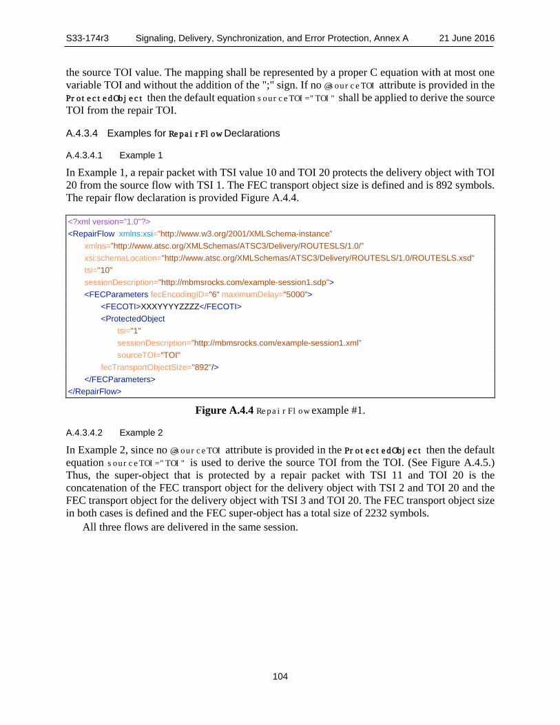
S33-174r3 Signaling, Delivery, Synchronization, and Error Protection, Annex A 21 June 2016
104
the source TOI value. The mapping shall be represented by a proper C equation with at most one variable TOI and without the addition of the ";" sign. If no @sourceTOI attribute is provided in the ProtectedObject then the default equation sourceTOI="TOI" shall be applied to derive the source TOI from the repair TOI.
A.4.3.4 Examples for RepairFlow Declarations
A.4.3.4.1 Example 1
In Example 1, a repair packet with TSI value 10 and TOI 20 protects the delivery object with TOI 20 from the source flow with TSI 1. The FEC transport object size is defined and is 892 symbols. The repair flow declaration is provided Figure A.4.4.
<?xml version="1.0"?> <RepairFlow xmlns:xsi=”http://www.w3.org/2001/XMLSchema-instance” xmlns=”http://www.atsc.org/XMLSchemas/ATSC3/Delivery/ROUTESLS/1.0/” xsi:schemaLocation="http://www.atsc.org/XMLSchemas/ATSC3/Delivery/ROUTESLS/1.0/ROUTESLS.xsd" tsi="10" sessionDescription="http://mbmsrocks.com/example-session1.sdp"> <FECParameters fecEncodingID="6" maximumDelay="5000"> <FECOTI>XXXYYYYZZZZ</FECOTI> <ProtectedObject tsi="1" sessionDescription=”http://mbmsrocks.com/example-session1.xml” sourceTOI="TOI" fecTransportObjectSize="892"/> </FECParameters> </RepairFlow>
Figure A.4.4 RepairFlow example #1.
A.4.3.4.2 Example 2
In Example 2, since no @sourceTOI attribute is provided in the ProtectedObject then the default equation sourceTOI="TOI" is used to derive the source TOI from the TOI. (See Figure A.4.5.) Thus, the super-object that is protected by a repair packet with TSI 11 and TOI 20 is the concatenation of the FEC transport object for the delivery object with TSI 2 and TOI 20 and the FEC transport object for the delivery object with TSI 3 and TOI 20. The FEC transport object size in both cases is defined and the FEC super-object has a total size of 2232 symbols.
All three flows are delivered in the same session.

S33-174r3 Signaling, Delivery, Synchronization, and Error Protection, Annex A 21 June 2016
105
<?xml version="1.0"?> <RepairFlow xmlns:xsi="http://www.w3.org/2001/XMLSchema-instance" xmlns="http://www.atsc.org/XMLSchemas/ATSC3/Delivery/ROUTESLS/1.0/" xsi:schemaLocation="http://www.atsc.org/XMLSchemas/ATSC3/Delivery/ROUTESLS/1.0/ROUTESLS.xsd" tsi="11" sessionDescription="http://mbmsrocks.com/example-session1.sdp"> <FECParameters fecEncodingID="6" maximumDelay="5000"> <FECOTI>XXXYYYYZZZZ</FECOTI> <ProtectedObject tsi="2" fecTransportObjectSize="892"/> <ProtectedObject tsi="3" fecTransportObjectSize="1340"/> </FECParameters> </RepairFlow>
Figure A.4.5 RepairFlow example #2.
A.4.3.4.3 Example 3
In Example 3, the FEC super-object that is protected by a repair packet with TSI 12 and TOI 20 is the concatenation of the FEC transport object for the delivery object with TSI 4 and TOI 40, the FEC transport object for the delivery object with TSI 5 and TOI 20 and the FEC transport object for the delivery object with TSI 4 and TOI 41. (See Figure A.4.6.) In this example, the FEC transport object sizes of the delivery objects are not included in the repair flow declaration.
Note that the sequence of the ProtectedObject declarations within a RepairFlow declaration determines the order of the FEC transport objects for the delivery objects in the super-object.
<?xml version="1.0"?> <RepairFlow xmlns:xsi="http://www.w3.org/2001/XMLSchema-instance" xmlns="http://www.atsc.org/XMLSchemas/ATSC3/Delivery/ROUTESLS/1.0/" xsi:schemaLocation="http://www.atsc.org/XMLSchemas/ATSC3/Delivery/ROUTESLS/1.0/ROUTESLS.xsd" tsi="12" sessionDescription="http://mbmsrocks.com/example-session1.xml"> <FECParameters fecEncodingID="6" maximumDelay="5000"> <FECOTI>XXXYYYYZZZZ</FECOTI> <ProtectedObject tsi="4" sourceTOI="2*TOI"/> <ProtectedObject tsi="5"/> <ProtectedObject tsi="4" sourceTOI="2*TOI+1"/> </FECParameters> </RepairFlow>
Figure A.4.6 RepairFlow example #3.
A.4.3.4.4 Example 4
In Example 4, a repair packet with TSI 13 and TOI 20 protects the delivery object with TSI 6 and TOI 21. (See Figure A.4.7.)

S33-174r3 Signaling, Delivery, Synchronization, and Error Protection, Annex A 21 June 2016
106
<?xml version="1.0"?> <RepairFlow xmlns:xsi="http://www.w3.org/2001/XMLSchema-instance" xmlns="http://www.atsc.org/XMLSchemas/ATSC3/Delivery/ROUTESLS/1.0/" xsi:schemaLocation="http://www.atsc.org/XMLSchemas/ATSC3/Delivery/ROUTESLS/1.0/ROUTESLS.xsd" tsi="13" sessionDescription="http://mbmsrocks.com/example-session1.xml"> <FECParameters fecEncodingID="6" maximumDelay="5000"> <FECOTI>XXXYYYYZZZZ</FECOTI> <ProtectedObject tsi="6" sourceTOI="TOI+1"/> </FECParameters> </RepairFlow>
Figure A.4.7 RepairFlow example #4.
A.4.3.4.5 Example 5
In Example 5, a repair packet with TSI 14 and TOI 10 protects the concatenation of the FEC transport objects for two delivery objects: the delivery object with TSI 7 and TOI 20 and the delivery object with TSI 7 and TOI 21. (See Figure A.4.8.) The following repair flow declaration with TSI 14 provides the static FDD.
<?xml version="1.0"?> <RepairFlow xmlns:xsi="http://www.w3.org/2001/XMLSchema-instance" xmlns="http://www.atsc.org/XMLSchemas/ATSC3/Delivery/ROUTESLS/1.0/" xsi:schemaLocation="http://www.atsc.org/XMLSchemas/ATSC3/Delivery/ROUTESLS/1.0/ROUTESLS.xsd" tsi="14" sessionDescription="http://mbmsrocks.com/example-session1.sdp"> <FECParameters fecEncodingID="6" maximumDelay="5000"> <FECOTI>XXXYYYYZZZZ</FECOTI> <ProtectedObject tsi="7" repairTOI="2*TOI"/> <ProtectedObject tsi="7" repairTOI="2*TOI+1"/> </FECParameters> </RepairFlow>
Figure A.4.8 RepairFlow example #5.
The ordering of the FEC transport objects in the FEC super-object is the same as the order in which the ProtectedObject declarations are made in the RepairFlow declaration. Thus, in example 5, the FEC super-object corresponding to a repair packet with TSI 14 and TOI 10 is the concatenation of the FEC transport object for the delivery object with TSI 7 and TOI 20 and the FEC transport object for the delivery object with TSI 7 and TOI 21.
A.4.4 Receiver Operation
A.4.4.1 Introduction
For robust reception, FEC may be applied. In this case, one or more repair flows are sent along with the source packet streams. The repair flow description is provided in Section A.4.3.2.
The crucial aspect of receiver operation in a ROUTE environment is the recovery of the delivery objects from incoming LCT packets along with additional information provided in the

S33-174r3 Signaling, Delivery, Synchronization, and Error Protection, Annex A 21 June 2016
107
signaling that describes the source and repair packet flows. The specific procedure depends on the implementation option, for example:
• No FEC is employed and the delivery object is to be recovered directly from the source packets.
• FEC is provided individually for each delivery object, i.e. no use of FEC super-objects as described in Section A.4.2.3.
• Single FEC scheme is used to protect a multitude of delivery objects, i.e. use of FEC super-objects.
• Multiple FEC schemes are used to protect different sets of delivery objects. In addition, it may be up to the receiver to decide to use zero, one or more of the FEC streams.
Hence, each flow is typically assigned an individual recovery property, which defines aspects such as the delay and the required memory if one or the other is chosen. The receiver may select one or more repair flows, depending on its mode of operation. The receiver may decide whether or not to utilize repair flows based on the following considerations:
• The desired start-up and end-to-end latency. If a repair flow requires significant amount of buffering time to be effective, such repair flow might only be used in time-shift operations or in poor reception conditions, since use of such repair flow trades off end-to-end latency against media presentation quality.
• FEC capabilities, i.e. the receiver may pick only the FEC algorithm that it supports. • Which source flows are being protected; for example, if the repair flow protects source
flows that are not selected by the receiver, then it may not select the repair flow. • Other considerations such as available buffer size, reception conditions, etc. If a receiver decides to acquire a certain repair flow then it must receive data on all source
flows that are protected by that repair flow to collect the relevant packets.
P1.1.0Delivery Object
Recoveryand FEC
P1.1.1000
Delivery Object
Processing
Delivery Session carrying Transport Sessions delivery objects
Signaling Metadata
Application/DASH player
API
P2.1.0
P2.1.0 P2.1.2000 P2.1.4000
R1.1.1 R1.2 R1.3 R1.4 R1.5
R2.1 R2.2 R2.3 R2.4 R2.5
Figure A.4.9 ROUTE receiver with FEC.

S33-174r3 Signaling, Delivery, Synchronization, and Error Protection, Annex A 21 June 2016
108
A.4.5 Example Operation To be able to recover the delivery objects that are protected by a repair flow, a receiver needs to obtain the necessary service signaling metadata fragments that describe the corresponding collection of delivery objects that are covered by this Repair Flow. A repair flow is defined by the combination of an LCT channel, a unique TSI number, as well as the corresponding protected source flows.
If a receiver acquires data of a repair flow, it is expected to collect all packets of all protected Transport Sessions.
Upon receipt of each packet, whether it’s a source or repair packet, the receiver proceeds with the following steps in the order listed.
1) The receiver is expected to parse the packet header and verify that it is a valid header. If it is not valid, then the packet shall be discarded without further processing.
2) The receiver is expected to parse the TSI field of the packet header and verify that a matching value exists in the service signaling for the Repair Flow or the associated Protected source flow. If no match is found, the packet shall be discarded without further processing.
3) The receiver processes the remainder of the packet, including interpretation of the other header fields, and using the Source FEC Payload ID (to determine the start_offset byte position within the source object), the Repair FEC Payload ID, as well as the payload data, reconstructs the decoding blocks corresponding to a FEC super-object as follows: a) For a source packet, the receiver identifies the delivery object to which the received
packet is associated, using the session information and the TOI carried in the payload header. Similarly, for a repair object the receiver identifies the FEC super-object to which the received packet is associated, using the session information and the TOI carried in the payload header.
b) For source packets, the receiver collects the data for each FEC super-object and recovers FEC super-objects in same way as in Section A.3.9.2. The received FEC super-object is then mapped to a source-block and the corresponding encoding symbols are generated.
c) With the reception of the repair packets, the FEC super-object can be recovered. d) Once the FEC super-object is recovered, the individual delivery objects can be
extracted.
A.4.6 Repair Protocol If FEC is included and @minBufferTime of the repair flow declaration is present, then @minBufferTime shall convey the minimum buffer time for the repair flow.
A.5 SECURITY CONSIDERATIONS Refer to ALC as defined in RFC 5775 [24].
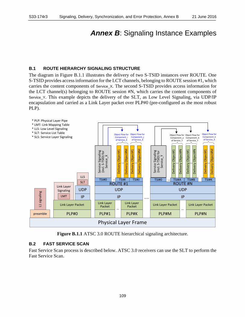
S33-174r3 Signaling, Delivery, Synchronization, and Error Protection, Annex B 21 June 2016
109
Annex B: Signaling Instance Examples
B.1 ROUTE HIERARCHY SIGNALING STRUCTURE The diagram in Figure B.1.1 illustrates the delivery of two S-TSID instances over ROUTE. One S-TSID provides access information for the LCT channels, belonging to ROUTE session #1, which carries the content components of Service_X. The second S-TSID provides access information for the LCT channel(s) belonging to ROUTE session #N, which carries the content components of Service_Y. This example depicts the delivery of the SLT, as Low Level Signaling, via UDP/IP encapsulation and carried as a Link Layer packet over PLP#0 (pre-configured as the most robust PLP).
Figure B.1.1 ATSC 3.0 ROUTE hierarchical signaling architecture.
B.2 FAST SERVICE SCAN Fast Service Scan process is described below. ATSC 3.0 receivers can use the SLT to perform the Fast Service Scan.
Link Layer Signaling
LLS
Physical Layer Frame
SLT
PLP#1
Link Layer Packet
PLP#Kpreamble PLP#M
Link Layer Packet
IP
UDPROUTE #N
PLP#N
Link Layer Packet
IP
UDP
Link Layer Packet..
.... TSI#I TSI#J
Deliv
ery
Obj
ect#
1
Deliv
ery
Obj
ect#
M
Deliv
ery
Obj
ect#
1
Deliv
ery
Obj
ect#
M
TSI#K
Deliv
ery
Obj
ect#
1
Deliv
ery
Obj
ect#
M
Object Flow forComponent_iof Service_X
Object Flow forComponent_jof Service_X
Object Flow forComponent_aof Service_Y
Object Flow forComponent_kof Service_X
Serv
ice
Sign
alin
g (in
cl. S
-TSI
D) fo
rSe
rvic
e_X
TSI#0
Serv
ice
Sign
alin
g (in
cl. S
-TSI
D) fo
rSe
rvic
e_Y
TSI#0 TSI#B
Deliv
ery
Obj
ect#
1
Deliv
ery
Obj
ect#
N
TSI#A
Deliv
ery
Obj
ect#
1
Deliv
ery
Obj
ect#
N
.. .. .. .. ..
Object Flow forComponent_bof Service_Y
ROUTE #1
..
....
PLP#0
Link Layer Packet
IP
UDP
L1 si
gnal
ing
* PLP: Physical Layer Pipe* LMT: Link Mapping Table* LLS: Low Level Signaling* SLT: Service List Table* SLS: Service Layer Signaling
LMT

S33-174r3 Signaling, Delivery, Synchronization, and Error Protection, Annex B 21 June 2016
110
Figure B.2.1 Fast service scan signaling flow.
The Fast Service Scan process is described here. 1) Tuner in receiver will step through frequencies using a predefined frequency list. 2) For each frequency, tuner determines if a signal is present. 3) When detecting a signal at a given frequency, the baseband processor will extract the
SLT and pass it to the middleware module which manages any type of data (e.g. signaling, audio/video/cc or app-based enhancement) and controls data to the appropriate parser and internal cache.
4) The middleware module will pass the SLT to the SLT parser. 5) The SLT parser parses the SLT and extracts the information which is essential for
producing a channel map (e.g. service id, short service name, broadcast SLS signaling information and hidden in the map).
6) Information is stored into the channel map.
B.3 ROUTE FULL SERVICE SCAN If receivers perform a full scan with service signaling (USBD or USD) for each service, they can store more abundant information. For example, a longer service name can be acquired from the USD, and it can be stored in the channel map by matching the service_id values in the SLT and the USD.
PHY Receiver
PLP
LLS
TunerATSC 3 . 0 Broadcast
Set frequencySet frequency
...
Wait until getting a signal…Wait until getting a signal…
3
1
2
9
Baseband
Frequency List = { 2, 3, … };
When detecting signal, get RF StreamWhen detecting signal, get RF Stream
RF Stream
Channel Manager
Channel Map
Signaling Manager
Store the channel information into the channel map
Store the channel information into the channel map
SLT parser
* PLP: Physical Layer Pipe* LMT: Link Mapping Table* LLS: Low Level Signaling* SLT: Service List Table* SLS: Service Layer Signaling
* PLP: Physical Layer Pipe* LMT: Link Mapping Table* LLS: Low Level Signaling* SLT: Service List Table* SLS: Service Layer Signaling
UDP / IP
... PLP
SLT
Link
Lay
er S
igna
ling
LMT
LMT parser 7Parse LMTParse LMT
8Parse SLTParse SLT
Preamble
L1 S
igna
ling
RF Stream
MiddlewareSignaling Manager
Channel Manager
...
PLP4 5
6

S33-174r3 Signaling, Delivery, Synchronization, and Error Protection, Annex B 21 June 2016
111
Figure B.3.1 ROUTE full-service scan signaling flow.
The steps for a full service scan are described here: 1) Tuner in receiver will step through frequencies using the pre-defined frequency list. 2) For each frequency, tuner will wait until it gets a signal. 3) When detecting a signal from a frequency, baseband processor will extract the SLT and
pass it to the middleware module. 4) Receivers should check the SLT_version is new or not. It is best to parse it even if it has the
same version number as on the last scan. The version number could have wrapped around and by chance be the same number as it was before. If the version is new, the middleware module can gather SLT and pass the SLT to the SLT parser.
5) SLT parser will parse the data, and extract the information 6) Information will be stored into the channel map. 7) Receiver gets the SLS Bootstrapping information from the SLT. 8) Receiver passes the SLS Bootstrapping information to the ROUTE client. 9) Receiver uses the signaling filtering scheme to extract the USD from the SLS and stores
it. 10) USD is parsed by the signaling parser. (It is best to parse it even if it has the same version
number as on the last scan. The version number could have wrapped around and by chance be the same number as it was before.)
11) Receivers can update the channel map by mapping with the service_id.
B.4 SERVICE ACQUISITION IN THE PURE BROADCAST (ONE ROUTE SESSION) When video and audio segments are delivered via pure broadcast with one ROUTE session, the service signaling will be structured like below.
PHY Receiver
Preamble
LLSTSI#0
TSI
S-TSID
ROU
TE session
USBD/USD
MPD
RF Stream
ROUTE Buffer
Cache
TunerATSC 3 . 0 Broadcast
Set frequencySet frequency
...
Wait until getting a signal…Wait until getting a signal…
3
1
2
Baseband
Frequency List = { 2, 3, … };
When detecting signal, get RF StreamWhen detecting signal, get RF Stream
RF Stream
Channel Manager
Channel Map
Signaling Manager
PLP
Get the SLS_Bootstrapping Information in the LMT and the SLT
Get the SLS_Bootstrapping Information in the LMT and the SLT
15
SLS to ROUTE BufferSLS to ROUTE Buffer Filtering SLSFiltering SLS
UDP
/IP
* PLP: Physical Layer Pipe* LMT: Link Mapping Table* LLS: Low Level Signaling* SLT: Service List Table* SLS: Service Layer Signaling
* PLP: Physical Layer Pipe* LMT: Link Mapping Table* LLS: Low Level Signaling* SLT: Service List Table* SLS: Service Layer Signaling
L1 Signaling
PLPPLP
...
Link Layer SignalingLMT
SLT...
video
audio
TSI
Middleware
check SLT version, if new, get SLTcheck SLT version, if new, get SLT
8
Signaling Manager
Channel Manager
...
SLTParser
SLSParser
LMTParser
7 Parse LMTParse LMT
Update the Channl Map mapping with service IDUpdate the Channl Map mapping with service ID
9 Parse SLTParse SLT
14 Parse SLSParse SLS
Store the channel information into the channel map
Store the channel information into the channel map
4
5
check LMT version, if new, get LMTcheck LMT version, if new, get LMT
6
10
111213
Buffer

S33-174r3 Signaling, Delivery, Synchronization, and Error Protection, Annex B 21 June 2016
112
Figure B.4.1 Service acquisition in the pure broadcast (one ROUTE session).
1) USD, S-TSID and MPD will be acquired together and should be parsed. All tables will be needed for service acquisition.
2) Select which Representations to present. In this case, S-TSID should be checked to determine which Representations are delivered via broadcast
3) Receivers will send the information from the signaling (USD, S-TSID and MPD) to the segment acquisition module providing the user preference with them. For example, user prefers the Spanish audio language over the English audio language.
4) In pure broadcast case, receivers can know where to get components without any deliveryMethod element in the USD.
B.5 SERVICE ACQUISITION IN THE PURE BROADCAST (MULTIPLE ROUTE SESSIONS) One service can be composed of multiple ROUTE sessions. In this case, the S-TSID will contain the additional ROUTE session information to allow access to all the Representations. However, this additional information may be optional to render the service.
Service Layer Signaling
SLT
service #2 service_id (#2) short_name (XYZ) service_category
SLS_Bootstrapping IP/Port (#2) PLP_ID (#4) tsi (sls)
USBD/USD
service #1 service_id (0x1001) short_service_name (ABC) service_category(TV) SLS_protocol_type(ROUTE) ... broadcast_signaling sIP (sIP1) dIP (dIP1) dPort (dPort1) PLP_ID (#1)
S-TSID
MPD
MPD period
UserServiceDescription @atscServiceId (0x1001) @atsc:fullMPDUri @atsc:STSIDUri @serviceId(urn:///USDServiceIdUri)
AdaptationSet segmentURL(video/Seg#1) representation (Rv)
AdaptationSet segmentURL(audio/Seg#1) representation (Ra)
Physical Layer Frame
PLP(#1)
SLT
ROUTE #1(sIP1dIP1
dPort1)PLP(#2)
LCT(tsi-a) Audio Segments
LCT(tsi-v) Video Segments......
LCT (tsi=0) Service Signaling
PLP(#4)
PLP(#5)
RS
LCT Channel @tsi-a SourceFlow ContentInfo(Ra)
LCT Channel @tsi-v @PLPID(#2) SourceFlow ContentInfo(Rv)
PLP(#0) UDP/IP

S33-174r3 Signaling, Delivery, Synchronization, and Error Protection, Annex B 21 June 2016
113
Figure B.5.1 Service acquisition in the pure broadcast (multiple ROUTE
sessions).
B.6 ESG BOOTSTRAPPING VIA BROADBAND ESG bootstrapping via broadband will be signaled in SLT. In this example, all ESG data will be delivered via broadband. Therefore, the ESG broadcast bootstrapping information will be replaced with the ESG broadband bootstrapping information – the attribute svcInetUrl@urlType will indicate if the type of URL is ESG or other. The details of the query mechanism to acquire the ESG data via broadband are outside the scope of this document.
Service Layer Signaling
SLT
service #2 service_id (0x1002) short_service_name (XYZ) service_category(TV) SLS_protocol_type (ROUTE) broadcast_signaling sIP(sIP3) dIP(dIP3) dPort (dPort3) PLP_ID (#3)
service #1 service_id (0x1001) short_service_name (ABC) service_category(TV) SLS_protocol_type (ROUTE) broadcast_signaling sIP(sIP1) dIP(dIP1) dPort (dPort1) PLP_ID (#1)
S-TSID
MPD
MPD period
AdaptationSet segmentURL(video/Seg#1) representation (Rv)
AdaptationSet representation(Ra) segmentURL(audio-a/Seg#1) representation(Ra2) segmentURL(audio-a2/Seg#1)
RS
LCT Channel @tsi-v SourceFlow ContentInfo(Rv)
LCT Channel @tsi-a SourceFlow ContentInfo(Ra)
SPA
Lang
uage
Audi
o Se
gmen
ts USBD/USD
S-TSID MPD
Service #1
Service #2
Physical Layer Frame
PLP(#1)
SLT
ROUTE #1sIP1/dIP1/dPort1 LCT(tsi-v) Video Segments
LCT(tsi-a) Audio Segments
LCT (tsi=0) Service Signaling
PLP(#2)
PLP(#3) ROUTE #3sIP3/dIP3/dPort3 LCT(tsi-v) Video Segments
LCT(tsi-a) Audio Segments
LCT (tsi=0) Service Signaling
ROUTE #2sIP2/dIP2/dPort2
LCT(tsi-a2) Audio Segments
RS @sIP=sIP2 @dIP=dIP2 @Port = dPort2 @PLP_ID = #2
LCT Channel @tsi-a2 SourceFlow ContentInfo(Ra2)
USBD/USD
UserServiceDescription @atscServiceId (0x1001) @atsc:fullMPDUri @atsc:STSIDUri @serviceId(urn:///USDServiceIdUri)
PLP(#0) UDP/IP

S33-174r3 Signaling, Delivery, Synchronization, and Error Protection, Annex B 21 June 2016
114
Figure B.6.1 ROUTE ESG bootstrapping via broadband.
B.7 ROUTE HYBRID (MULTIPLE AUDIO LANGUAGE) When two or more audio components in different languages are delivered via different delivery paths, one via broadcast and another via broadband, the S-TSID describes all the broadcast components so that the ROUTE client can retrieve the desired components. Moreover, the USD contains URL patterns for broadband and URL patterns for broadcast, so that when a DASH client issues a request for a Segment, the receiver middleware can describe which Segments will be delivered through which path. The middleware will then know which Segments to request from a remote broadband server, and which ones to look for in the broadcast.
PLP #2
Physical Layer Frame
PLP #1
SLT
ROUTEsIP1dIP1
dPort1 LCT(tsi-v) Video Segments
SLT
service_id = 0x1001service_data_version=0x01service_category=0x01(TV)SLS_protocol_type (ROUTE)..broadcast_signaling_location
...
SLS (Service Layer Signaling)
USBD/USD
MPD
S-TSID
RS
@atscServiceId = 0x1001…
LCT (tsi=0) Signaling
PeriodAdaptationSet
AdaptationSet
Representation(Audio Segment) @reptnID =com-a...
LCT Channel@tsi = tsi-v
SrcFlow ContentInfo=com-v...
LCT Channel@tsi = tsi-a
SrcFlow ContentInfo =com-a...
Representation(Video Segment)@reptnID =com-v...
Period
sIP (sIP1)dIP (dIP1)dPort (dPort1)PLP_id (#1)
SLS_URL=http://esg/sgdd.xml
LCT(tsi-a) Audio Segments
Broadband
ESG
PLP #0 UDP/IP

S33-174r3 Signaling, Delivery, Synchronization, and Error Protection, Annex B 21 June 2016
115
Figure B.7.1 ROUTE hybrid (multiple audio languages).
B.8 HANDOFF (BROADCAST TO BROADBAND, AND BACK) Receivers can hand off reception from broadcast to broadband and back using the signaling described in the USD. The USD describes which components will be delivered via broadcast or broadband. The receiver middleware can retrieve the components from broadcast when that is possible or from broadband if broadcast reception is lost.
Service Layer Signaling
SLT
USBD/USD
service #1 service_id (0x1001) short_name (ABC) service_category(TV) SLS_protocol_type(ROUTE) ... broadcast_signaling sIP(sIP1) dIP(dIP1) dPort(dPort1) PLP_ID (#1)
S-TSID
RS
LCT Channel @tsi-v SourceFlow ContentInfo(Rv)
LCT Channel @tsi-a SourceFlow ContentInfo(Ra)
MPD
MPD period
service @atscServiceId (0x1001) @atscFullMPDUri @atscSTSIDUri DeliveryMethod
atsc:BroadcastAppService basePattern (video)
atsc:BroadcastAppService basePattern (audio/eng)
AdaptationSet segmentURL(video/Seg#1) representation (Rv)
AdaptationSet segmentURL(audio/eng/Seg#1) representation (Ra)
Broadband
Spanish Audio Segments
atsc:unicastAppService basePattern (audio/spa)
AdaptationSet segmentURL(audio/spa/Seg#1) representation (Ra)
Physical Layer Frame
PLP(#1)
SLT
ROUTE #1sIP1dIP1
dPort1
LCT(tsi-v) Video Segments
LCT(tsi-a) Audio Segments
LCT (tsi=0) Service Signaling
...
PLP (#0) UDP/IP

S33-174r3 Signaling, Delivery, Synchronization, and Error Protection, Annex B 21 June 2016
116
Figure B.8.1 Handoff (broadcast to broadband, and back).
B.9 SCALABLE CODING (CAPABILITY IN THE USD) Receivers can do scalable coding using one service.
Service Layer Signaling
ROUTE #1sIP1dIP1
dPort1
SLT
MPD
MPD period
AdaptationSet segmentURL(video/bc/Seg#1) representation (Rv)
AdaptationSet segmentURL(audio/bc/Seg#1) representation (Ra)
Broadband
Video Segments
Physical Layer Frame PLP(#1)
SLT
LCT(tsi-v) Video Segments
LCT(tsi-a) Audio Segments
LCT (tsi=0) Service Signaling
...
Audio Segments
AdaptationSet segmentURL(video/bb/Seg#1) representation (Rv)
AdaptationSet segmentURL(audio/bb/Seg#1) representation (Ra)
service #1 service_id (0x1001) short_name (ABC) service_category(TV) SLS_protocol_type(ROUTE) broadcast_signaling sIP(sIP1) dIP(dIP1) dPort(dPort1) PLP_ID (#1)
USBD/USDS-TSID
RS
LCT Channel @tsi-v SourceFlow ContentInfo(Rv)
LCT Channel @tsi-a SourceFlow ContentInfo(Ra)
service @atscServiceId (0x1001) @atscFullMPDUri @atscSLSIDUri DeliveryMethod
atsc:BroadcastAppService basePattern (video/bc)
atsc:BroadcastAppService basePattern (audio/bc)
atsc:unicastAppService basePattern (video/bb)
atsc:unicastAppService basePattern (audio/bb)
UDP/IPPLP(#0)

S33-174r3 Signaling, Delivery, Synchronization, and Error Protection, Annex B 21 June 2016
117
Figure B.9.1 Scalable coding (capability in USD).
1) The USD includes all capabilities that are essential to render the service. In this example, the video resolution is the essential capability to decode the video, so the capability in the USD will have the value as ‘HD or UHD’ (as well as capabilities for other components, such as audio or closed captions or perhaps applications). It means that this program will serve the HD or UHD service now.
2) Receivers can know which component will be presented to render UHD service or HD service by using MPD.
B.10 SLT DELIVERY PATH The PLP carrying the SLT can be used to deliver service components as well.
Service Layer SignalingSLT
USBD/USDservice #1 service_id (0x1001) short_service_name (ABC) service_category(TV) SLS_protocol_type(ROUTE) ...
broadcast_signaling sIP(sIP1) dIP(dIP1) dPort(dPort1) PLP_ID (#1)
S-TSID
MPD
MPD period
UserServiceDescription@atscServiceId(0x1001)@atsc:fullMPDUri@atsc:STSIDUri capabilities = (UHD or HD)
AdaptationSet segmentURL(video/bc/Seg#1) representation (Rev) @dependencyId(Rv) representation (Rv)
Physical Layer Frame
PLP(#1)
SLT
LCT(tsi-a) Audio Segments
LCT(tsi-v) Video Segments
LCT (tsi=0) Service Signaling
RS
LCT Channel @tsi-v @PLP_ID (#2) SourceFlow ContentInfo(Rv)
LCT Channel @tsi-a SourceFlow ContentInfo(Ra)
LCT Channel @tsi-ev @PLP_ID (#3) SourceFlow ContentInfo(Rev)
AdaptationSet segmentURL(audio/bc/Seg#1) representation (Ra)
LCT(tsi-ev) Video Segments
PLP(#2)
PLP(#3)
1
2
ROUTE#1sIP1dIP1
dPort1
PLP(#0) UDP/IP
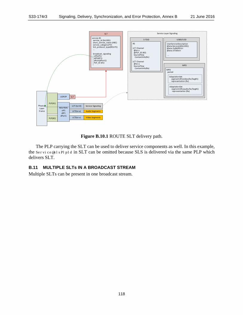
S33-174r3 Signaling, Delivery, Synchronization, and Error Protection, Annex B 21 June 2016
118
Figure B.10.1 ROUTE SLT delivery path.
The PLP carrying the SLT can be used to deliver service components as well. In this example, the Service@slsPlpId in SLT can be omitted because SLS is delivered via the same PLP which delivers SLT.
B.11 MULTIPLE SLTs IN A BROADCAST STREAM Multiple SLTs can be present in one broadcast stream.
Service Layer SignalingSLT
USBD/USDservice #1 service_id (0x1001) short_service_name (ABC) service_category(TV) SLS_protocol_type(ROUTE) ...
broadcast_signaling sIP(sIP1) dIP(dIP1) dPort(dPort1) PLP_ID (#1)
S-TSID
MPD
MPD period
UserServiceDescription@atscServiceId(0x1001)@atsc:fullMPDUri@atsc:STSIDUri ...
AdaptationSet segmentURL(video/bc/Seg#1) representation (Rv)
Physical Layer Frame
PLP(#1)
SLT
LCT(tsi-a) Audio Segments
LCT(tsi-v) Video Segments
LCT (tsi=0) Service Signaling
RS
LCT Channel @tsi-v @PLP_ID (#2) SourceFlow ContentInfo(Rv)
LCT Channel @tsi-a SourceFlow ContentInfo(Ra)
AdaptationSet segmentURL(audio/bc/Seg#1) representation (Ra)
PLP(#2)
ROUTE#1sIP1dIP1
dPort1
UDP/IP

S33-174r3 Signaling, Delivery, Synchronization, and Error Protection, Annex B 21 June 2016
119
Figure B.11.1 Multiple SLTs.
Service Layer Signaling
SLTBSID
USBD/USD
service #1 service_id (0x1001) short_name (ABC) SLS_protocol_type(ROUTE) ... broadcast_signaling sIP(sIP1) dIP(dIP1) dPort (dPort1)
S-TSID
MPD
MPD period
UserServiceDescription
@atscServiceId (0x1001) ...
AdaptationSet segmentURL(video/Seg#1) representation (Rv)
AdaptationSet segmentURL(audio/Seg#1) representation (Ra)
RS
LCT Channel @tsi-v SrcFlow ContentInfo(Rv)
LCT Channel @tsi-a SrcFlow ContentInfo(Ra)
Service Layer Signaling
Physical Layer Frame(BSID)
PLP(#1)
SLT
ROUTE #1sIP1dIP1
dPort1LCT(tsi-v) Video Segments
LCT(tsi-a) Audio Segments
LCT (tsi=0) Service Signaling
PLP(#2)
packet-v Video MPUs
packet-a Audio MPUsM
MT
Sign
alin
g M
essa
ge
MMTP #1dIP2
dPort2
packet-signaling
MMT signaling Message
UDP/IP
SLTUDP/IP
USBD/USD
UserServiceDescription
@atscServiceId (0x1002) ...
SLTBSID
service #2 service_id (0x1002) short_name (XYZ) SLS_protocol_type(MMTP) ...
broadcast_signaling dIP(dIP2) dPort (dPort2)

S33-174r3 Signaling, Delivery, Synchronization, and Error Protection, Annex C 21 June 2016
120
Annex C: Filtering for Signaling Fragments
To enable ATSC 3.0 receiver quick filtering of target signaling fragment, the LCT TOI field shall be split into three parts:
• Fragment Type — identifies the type of signaling fragment. • Fragment Type Extension — identifies the sub-type of the fragment. One example use-
case to allocate sub-type is to indicate types of fragments in bit-map format that are contained in the object to filter out the individual fragment in the case of carrying multiple fragments. Another use-case is to indicate instance identifier when multiple instances of signaling fragment with same Fragment Type are delivered. e.g. multiple MPDs near program boundaries.
• Version — identifies the version of the object identified by Fragment Type and Fragment Type Extension part.
Bit assignment for each part shall be as defined in Figure C.1.
0 1 2 3 0 1 2 3 4 5 6 7 8 9 0 1 2 3 4 5 6 7 8 9 0 1 2 3 4 5 6 7 8 9 0 1 +-+-+-+-+-+-+-+-+-+-+-+-+-+-+-+-+-+-+-+-+-+-+-+-+-+-+-+-+-+-+-+-+ | Fragment Type | Fragment Type Extension | Version | +-+-+-+-+-+-+-+-+-+-+-+-+-+-+-+-+-+-+-+-+-+-+-+-+-+-+-+-+-+-+-+-+
Figure C.1 Example for TOI bit assignment.
Fragment Type – The value to be assigned to identify each type of Service Layer Signaling fragment which this object is carrying. The value for each type of fragment shall be as defined in Table C.1. The Fragment Type “Packaged” indicates that the fragment is included in a file object formatted as Content-Type multipart/related.
Table C.1 Fragment Type Values Value Fragment Type 0x00 Reserved 0x01 Packaged 0x02 USBD/USD 0x03 S-TSID 0x04 MPD 0x05 APD ≥ 0x06 Reserved
Fragment Type Extension – When the object contains multiple fragments, a bit map indicating which fragments are contained in it. When the object contains a single fragment, the value is derived from the identifier of Service Signaling fragment. The value for each type of fragment shall be as defined in Table C.2.
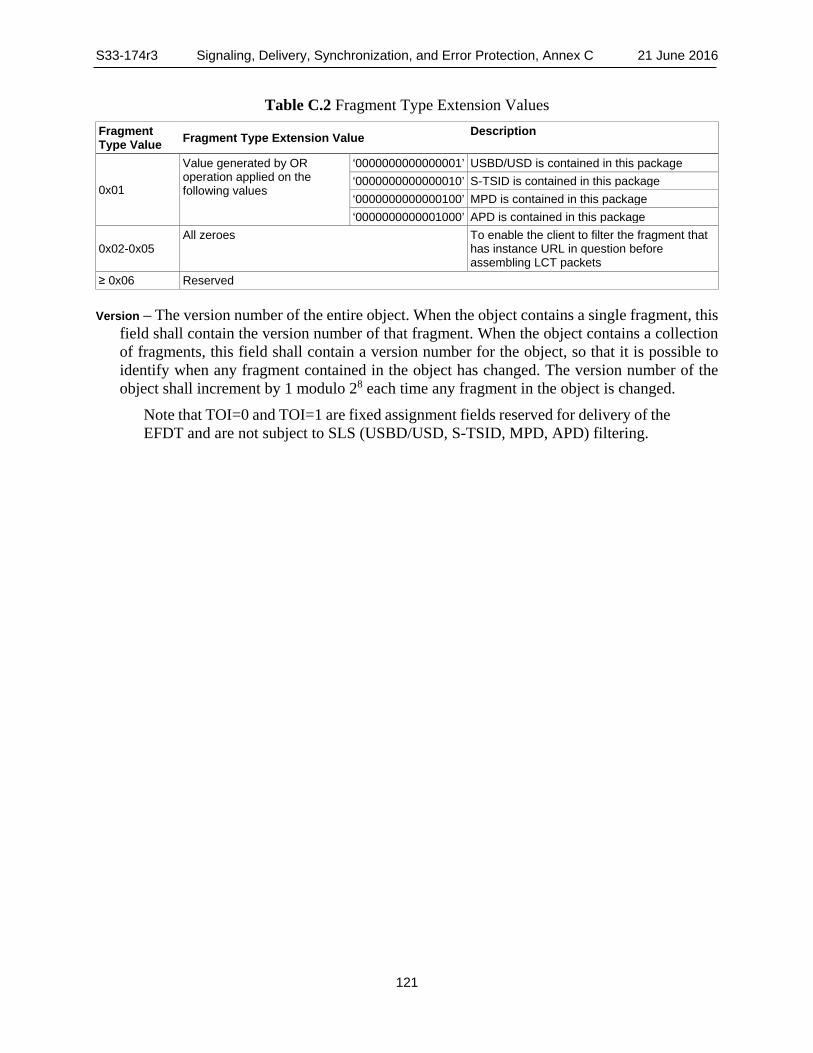
S33-174r3 Signaling, Delivery, Synchronization, and Error Protection, Annex C 21 June 2016
121
Table C.2 Fragment Type Extension Values Fragment Type Value Fragment Type Extension Value Description
0x01
Value generated by OR operation applied on the following values
‘0000000000000001’ USBD/USD is contained in this package ‘0000000000000010’ S-TSID is contained in this package ‘0000000000000100’ MPD is contained in this package ‘0000000000001000’ APD is contained in this package
0x02-0x05 All zeroes To enable the client to filter the fragment that
has instance URL in question before assembling LCT packets
≥ 0x06 Reserved
Version – The version number of the entire object. When the object contains a single fragment, this field shall contain the version number of that fragment. When the object contains a collection of fragments, this field shall contain a version number for the object, so that it is possible to identify when any fragment contained in the object has changed. The version number of the object shall increment by 1 modulo 28 each time any fragment in the object is changed.
Note that TOI=0 and TOI=1 are fixed assignment fields reserved for delivery of the EFDT and are not subject to SLS (USBD/USD, S-TSID, MPD, APD) filtering.

S33-174r3 Signaling, Delivery, Synchronization, and Error Protection, Annex D 21 June 2016
122
Annex D: Template-based Compression
D.1 DIFF AND PATCH OPERATION An XML signaling fragment can be compressed not only using compression tools like gzip but also by alternative means such as the diff and patch tools. In the diff and patch process, an XML signaling template is pre-shared between sender and receivers. The process at the sender compares two XML files, the XML signaling template and the XML signaling instance, and produces an output of the difference between the two, referred to as Diff.
Diff is encapsulated in the element metadataEnvelope as an ordinary XML signaling instance. When Diff is generated by the sender, Diff is encapsulated in the element update then encapsulated in the metadataEnvelope. Diff is delivered to multiple receivers through the signaling channel. The receiver captures it and checks if content of element metadataFragment contains element diffUpdate, if it does, the receiver recognizes it has to be handled in this compression mode.
The receiver looks for signaling template of attribute metadataURI - SignalingTemplateID with optional attribute version - SignalingTemplateVersion in cache stores pre-shared signaling templates. If not found, the receiver will try to GET the signaling template with url of SignalingTemplateID.
The receiver recovers signaling instance by applying delivered Diff on retrieved signaling template. The instantiated signaling fragment will have a pair of attribute metadataURI - SignalingInstanceID and attribute version - SignalingInstanceVersion. Only difference between updated part against template (e.g. element or attribute value added, changed or removed, etc.) needs to be transported rather than the complete file. It is obvious that it could gain much more efficiency by diff and patch operation rather than ordinary compression schemes if the differences are very small compared to the original complete fragment.
The metadata envelope and metadata fragment may be compressed using gzip as described in MBMS [9].
The following XML instance notation shows how Diff is encapsulated in the element metadataEnvelope.
<metadataEnvelope xmlns="urn:3gpp:metadata:2005:MBMS:envelope"> <item metadataURI="SignalingInstanceID" version="SignalingInstanceVersion"> <metadataFragment> <![CDATA[<diffUpdate> <templateID>SignalingTemplateID</templateID> <templateVersion>SignalingTemplateVersion</templateVersion> - optional <update>Diff</update> </diffUpdate>]]> </metadataFragment> </item> </metadataEnvelope>
Figure D.1.1 illustrates the principles.

S33-174r3 Signaling, Delivery, Synchronization, and Error Protection, Annex D 21 June 2016
123
Figure D.1.1 Template based signaling fragment compression.
D.2 DIFF REPRESENTATION The difference representation shall be an XML patch compliant to the XML Patch Operations framework as defined in RFC 5261 [21] and referenced in “MPD Patch” as adopted in DASH.
D.3 TEMPLATE PRE-SHARING The signaling template fragment is identified by the url contained in the element templateID. The template itself is pre-shared by being fetched through HTTP(S) over broadband. When the receiver gets the diff message for the first time is cached for future use.
Signaling Consumer Signaling Producer
Diff Diff Generator Diff Applier
Pre Shared
Receiver Sender
Identified by SignalingInstanceID &
SignalingInstanceVersion
Identified by SignalingTemplateID & SignalingTemplateVersion
Signaling Instance
Signaling Instance
Signaling Template
Signaling Template

S33-174r3 Signaling, Delivery, Synchronization, and Error Protection, Annex E 21 June 2016
124
Annex E: Acquisition and Playback of Service Using MMTP
E.1 INTRODUCTION A single MMT Package can be delivered over one or more MMTP sessions, each of which can be identified by a destination IP address and a destination UDP port number. In a broadcast system, a single RF channel can contain one or more logical channels, called PLPs (Physical Layer Pipe), and each PLP can carry one or more MMTP sessions. In addition, one MMTP session can be carried by more than one PLP.
In order to present a selected MMT Package, the receiver acquires MMTP packets carrying the selected MMT Package. MMT signaling messages provide information on MMTP sessions carrying the MMTP packets, which can include a destination IP address, a destination UDP port number and a PLP id for each MMTP session. Note that multiple MMT Packages can be delivered by a single MMTP session and that multiple MMT Packages in the same service can be delivered simultaneously. Such MMT Packages do not overlap in their presentation times.
E.2 MAPPING BETWEEN THE PHYSICAL LAYER AND MMTP SESSIONS A single RF channel may contain multiple PLPs and each PLP can carry one or more services. Furthermore, each service can be delivered over multiple MMTP sessions. Figure E.2.1 shows an example of an RF channel consisting of two PLPs carrying three MMTP sessions. Here a single RF channel (RF channel 1) carries two PLPs, namely PLP1 and PLP2. In PLP1, two MMTP sessions are multiplexed while there is only one MMTP session in PLP2.
In order to tune-in to a selected service, the receiver must know the location of MMTP sessions carrying the MMT Package associated with the selected service. The location of the MMTP sessions can be represented by a combination of an identifier of a broadcast stream, an identifier of a PLP, a destination IP address and a destination UDP port number all of which can be obtained from the SLT and MMT signaling messages.

S33-174r3 Signaling, Delivery, Synchronization, and Error Protection, Annex E 21 June 2016
125
RF channel 1
PLP 1
PLP 2
MMTP session #1(destination IP add: w1.x.1.y1.z1
destination UDP port : p1)
MMTP session #3(destination IP add: w3.x3.y3.z3
Destination UDP port: p3)
MMTP session #2(destination IP add: w2.x2.y2.z2
destination UDP port: p2)
Figure E.2.1 A PHY channel consisting of two PLPs.
E.3 SERVICE ACQUISITION This section describes a service acquisition process under the assumption that all of the service components are delivered in a single RF channel by a single MMTP session. During the channel scan, the SLS Bootstrapping information for the services carried by MMTP sessions can be acquired from the SLT. The USBD for the services can be obtained from the MMTP sessions signaled by the SLT.

S33-174r3 Signaling, Delivery, Synchronization, and Error Protection, Annex E 21 June 2016
126
Package
V
A
CC
RF
PLP(#1) SLT
PLP(#2) MMTPsession
V
A
CC
MMTSig.
① Initial scan① Initial scan
Channel Map
② Service selection② Service selection
③ Tune-in to theMMTP session③ Tune-in to the
MMTP session
Filter MPI message
HRBM message
ALFEC message
FECDecoding
BufferDe-jitterBuffer
MMTPDecap.Buffer
④ Receiving the MMTP session④ Receiving the MMTP session
⑤ Acquisition of Signaling Messages⑤ Acquisition of
Signaling Messages
FECDecoder
⑥⑥
⑦⑦ ⑧⑧
⑨ AU⑨ AU
HRBMHRBM
Decoder
Decoder
⑩⑪ Presenting Service
⑩⑪ Presenting Service
MPT message
Figure E.3.1 MPU broadcast streaming channel change.
The steps 1-11 for the service acquisition shown in Figure E.3.1 above are: 1) The client acquires a Service List Table (SLT) containing information for rapid channel
scan and Service Signaling messages containing service layer information including the MMT_package_id of a service and the location of the MPT message for the corresponding the MMT_package_id.
2) The User selects a Service and its MMT_package_id are identified. 3) Service selection is preceded by an RF channel and the PLP selection using information
stored during the channel scan. The MMTP session carrying the MPT message associated for the selected service is acquired.
4) In the referenced MMTP session for the selected channel, MMTP packets containing various content components and signaling messages are obtained.
5) The receiver searches for MMTP packets carrying an MMT signaling message by looking at the type field of MMTP packet headers to locate MMTP packets containing signaling messages. The MP table extracted from the MPT message is processed to get the list of MMT assets (ATSC 3.0 content components) comprising the selected Service corresponding to the MMT_package_id. The MP table also provides other necessary

S33-174r3 Signaling, Delivery, Synchronization, and Error Protection, Annex E 21 June 2016
127
information related to each asset such as packet_id, MMT_general_location_info, MPU_timestamp_descriptor, etc. Other MMT signaling messages, including MPI, HRBM and AL_FEC signaling messages are processed if necessary.
6) From the series of MMTP packets received, MMTP packets with packet_ids corresponding to each content component are selected (filtered) and stored in their corresponding FEC Decoding Buffers. MMTP packets with repair symbols corresponding to each content component are also received and stored separately.
7) MMTP packets received at the FEC Decoding Buffer are immediately copied into a corresponding De-jitter Buffer and the packet_sequence_number of each MMTP packet is checked to detect missing packets. If some packets are not received by the predefined time given by an AL_FEC message, then the AL-FEC code is applied to recover the missing packets, and the recovered packets are copied to the De-jitter Buffer immediately.
8) MMTP packets are buffered (delayed) at the De-jitter Buffer as instructed by HRBM parameters, which are obtained from HRBM signaling messages in step 5).
9) MMTP packets of MPUs are processed to allow Access Unites (AUs) of components to be decoded.
10) The first AU in an MPU is decoded by the appropriate decoder and presented at the time signaled in the MPU_timestamp_descriptor() (or MPI message if present). The timing information is provided by the server and embedded in the emission though an MMT Signaling message. The descriptor (or MPI message) instructs the associated decoder when the content being decoded is to be presented.
11) The next AU in the MPU is decoded and presented after the presentation time specified in the MPU’s ‘stts’ box and ‘ctts’ box has passed after the presentation of the first AU. This step is repeated until the last AU of the MPU has been decoded and presented.
S33-174r3 Signaling, Delivery, Synchronization, and Error Protection, Annex F 21 June 2016
128
Annex F: Rating Region Table Requirements
F.1 INTRODUCTION This annex normatively specifies the minimum requirements for the Rating Region Table (RRT) data structure. Details are expected to be provided as needed by regulatory or standards-making bodies within each region.
F.2 RRT REQUIREMENTS The broadcast emission may include one or more RRTs, each corresponding to a particular identified value of Rating Region. RRTs shall be delivered encoded with XML instance documents. Each instance shall contain at least one, but not more than two, RRTs. The following specifications provide the general rules for construction of RRT instance documents.
RRTs shall be contained within the RatingRegionTables element, with the characteristics given in Table F.2.1.
The RRT shall be represented as an XML document containing a RatingRegionTables root element that conforms to the definitions in the XML schema that has namespace
http://www.atsc.org/XMLSchemas/ATSC3/RRT/1.0/
The definition of this schema is in a schema file accompanying this standard, as described in Section 3.6 above.

S33-174r3 Signaling, Delivery, Synchronization, and Error Protection, Annex F 21 June 2016
129
Table F.2.1 RatingRegionTables Element Structure Element or Attribute Use Data Type Description RatingRegionTables 1 RatingRegionTable 1..2 One or two Rating Region Tables. RegionIdentifier 1 Information about the region @regionIdentifier 1 unsignedByte Identifies the rating region described. RegionIdText 1..N TextType Human-readable string describing the rating
region, e.g. “Canada.” See Table F.2.2. Dimension 1..N One or more elements, each describing one
rating dimension in the rating region @dimensionLevels 1 unsignedByte The number of levels for content advisory in
this dimension. Shall not be zero. DimensionTitle 0..N TextType Human-readable string describing the
dimension. See Table F.2.2. @dimensionGraduated 0..1 boolean If the dimension describes ratings in a
graduated scale, the value of dimensionGraduated shall be TRUE, otherwise the value of dimensionGraduated shall be FALSE. Default value (if not present) shall be FALSE. When ratings are defined to be on a graduated scale, higher rating values represent increasing levels of rated content within the dimension.
Rating 1..N Definition of each rating in the Dimension @ratingValue 1 unsignedByte The rating level value in integer form RatingValueAbbrev 1..N TextType Abbreviated human-readable string
describing the rating value. See Table F.2.2. RatingValueString 1..N TextType Human-readable string describing the rating
value. See Table F.2.2.
Table F.2.2 TextType Element Structure Element or Attribute Use Data Type Description TextType 1 string @lang 0..1 lang The language of the string specified
according to BCP 47 [27].

S33-174r3 Signaling, Delivery, Synchronization, and Error Protection, Annex G 21 June 2016
130
Annex G: Emergency Alert Signaling
G.1 EMERGENCY ALERT SYSTEM STRUCTURE
G.1.1 Overview of the System With ATSC 3.0, the following types of emergency information can be delivered to TV receivers:
• Emergency Alert wake-up bits – allow a viewer to become aware of an emergency even when it is in standby mode.
• Emergency Alert System (EAS) messages – normally broadcast today (2015) as “burned in” to the audio and video of a service.
• Extended Common Alerting Protocol (CAP) messages – XML documents based on version 1.2 of the CAP specification [35].
Note: possible ATSC-defined extensions to CAP are under discussion.
• Emergency Alert Application (EAA) – A broadcaster application conforming to the ATSC 3.0 Runtime Environment [38] which can provide further information pertaining to the alert.
• Rich media files – content files that provide additional information about an emergency alert. These rich media files may be referenced from within the CAP message, or may be resources used by the EAA.
• Emergency-related programming – programming such as local news coverage that provides viewers with information about the ongoing emergency
More information about each of these is provided below. Figure G.1.1 below illustrates the overall Emergency Alert System architecture.
:Emergency Alert
(CAP1.2)
Broadcast(CAP1.2 extension)
EA Authority Broadcaster Receiver
IPAWS
Local EA Info
ServerBroadband
Figure G.1.1 High level architecture of an Emergency Alert system.
• Alert Authorities can provide Emergency Alert System (EAS) messages to broadcasters via the Emergency Alert System network, and/or they can provide CAP messages to

S33-174r3 Signaling, Delivery, Synchronization, and Error Protection, Annex G 21 June 2016
131
broadcasters via the IPAWS network. Broadcasters can convert CAP messages to EAS messages for presentation to viewers when necessary. Multiple CAP messages from multiple sources can be merged into a single CAP message.
• Broadcasters may add or modify information in CAP messages before delivering them. • Broadcasters may also add rich media references to CAP messages and broadcast the rich
media files as well as the CAP messages. • Broadcasters may distribute and launch an Emergency Alert Application coincident with
the alert in order to provide viewers with further information related to the event, optionally including interactive elements. Such further information could include school closing information, modifications to bus routes, locations of emergency shelters, or recommendations for dealing with the emergency.
G.1.2 Flow of Emergency Alert Signaling and Rich Media Contents Figure G.1.2 below provides a more detailed view of example flows of emergency alert information.
Figure G.1.2 Emergency Alert data flows.
In the example shown in the upper-left of Figure G.1.2, an EA Authority notifies a Broadcaster of an emergency alert event by means of a CAP message9. The broadcaster receives the CAP message and processes it. Based on the broadcaster’s option (for all types of alerts except the national-level Emergency Action Notification) any given CAP message may be disregarded, or it may be passed on (after processing) within the broadcaster’s program content to the public. Some CAP messages may be discarded by the broadcaster because they are not deemed important enough to interrupt normal programming. Others may be discarded because the severity is low, or the area impacted is small or outside the coverage area of the broadcast.
9 Notification methods other than use of the CAP message are possible.
CAPMessage
EA Authority
Broadcaster 's EA Info
CAPMessage
resource:
Live shoot ing
pre-recorded
Encoder
EA I nform ation
EAApplicat ionGenerator
EAApplicat ion
Applicat ion Signaling
text, audio, control
Mux
er/M
odCo
dBroadcaster ’s CAP Message
De-
Mux
er/D
e-M
odCo
d
A/ V Content
Media Player
Runtim e Environm ent
BroadcastProcessor
BroadbandProcessor
BrowserAppManager
VA
V(burned-in text)
A1A2
Broadcaster Receiver
Emergency Aler t applicat ion
EAS not ificat ion
CAP message
V(burned-in text)
A1A2
EA Application Server
resource
:Rich Media
resource:
CAP Parser/Renderer

S33-174r3 Signaling, Delivery, Synchronization, and Error Protection, Annex G 21 June 2016
132
If the broadcaster decides to disseminate the contents of a particular incoming CAP message, after editing, it can be included in the broadcast multiplex (as “Broadcaster’s CAP Message” in the figure. The text of the CAP message may be edited within the broadcast plant before being passed to viewers, for example to remove parts of it that pertain only to first responders or agencies. The broadcaster also has the option to add rich media elements such as graphics or even multimedia (e.g. video or audio clips).
The incoming CAP message may also be passed to an “EA Application Generator,” which could generate a broadcaster application (or content for an existing application) to be distributed and used by the application runtime environment in the ATSC 3.0 receiver to provide an interactive experience related to the emergency.
The block labeled “Receiver” on the right side of Figure G.1.2 includes audio/video rendering and supports the ATSC 3.0 runtime application environment. As shown, depending on the format of the URLs referencing EA content, the rich media files can be provided either via broadband access to the EA App Server, or via broadcast delivery.
The block labeled “Application Signaling” can cause application resources such as media files usable by the application to be distributed. The URLs in the CAP message referencing rich media may be resolved by either the broadcast or the broadband path, depending on the broadcaster’s choice for file distribution.
Green arrows in Figure G.1.2 represent emergency information included in video (“burned-in”) or included in the audio program content.
G.2 MEANING OF WAKE-UP BITS Two wake-up bits are delivered in the physical layer. They are delivered in such a way that it is possible for a TV receiver to detect them even when the receiver is in “standby” mode, as specified in [3]. These bits allow receivers to detect that emergency information is available for display to users and also to detect a “wake-up version” so that a wake-up that was dismissed by a user can be distinguished from a new wake-up (i.e., for a new, but concurrent emergency situation).
The two wake-up bits specified in [3] are: • ea_wake_up_1 within bootstrap_symbol_1() as specified in Table 6.2 of [3] • ea_wake_up_2 within bootstrap_symbol_2() as specified in Table 6.4 of [3] These two bits are concatenated together to form a 2-bit value, with ea_wake_up_1 forming the
least-significant bit and ea_wake_up_2 forming the most significant bit. Table G.2.1 illustrates the meaning of the wake-up bits.
Table G.2.1 Meaning of Wake-up Bits Value Meaning ‘00’ No emergency to wake up devices is currently signaled ‘01’ Emergency to wake up devices - setting 1 ‘10’ Emergency to wake up devices - setting 2 ‘11’ Emergency to wake up devices - setting 3
When the wake-up bits value changes from 0 to 1, this indicates a wake-up call for an emergency. When the numerical setting number increments from 1 to 2, 2 to 3, 3 to 1, etc. this indicates a new wake-up call. When the value of the bits return to 0, it means an emergency wake-up is no longer being signaled.

S33-174r3 Signaling, Delivery, Synchronization, and Error Protection, Annex G 21 June 2016
133
Emergency-related signaling and content may be delivered without turning on the wake-up bits. However, it is recommended that whenever the wake-up bits are set, some aspect of a new emergency message communication should be made available. This may include available rich media files, a burned-in video/audio message, emergency-related programming, and/or an extended CAP message.
G.3 EMERGENCY ALERT SYSTEM OPERATION In the alerting system currently deployed in the U.S., each EAS message that is burned into the audio/video programming starts with an audio tone to announce its presence. This is followed by text overlaid on the video, as a static or scrolled banner, and by audio either in a secondary audio channel or replacing the program audio in the audio track. The total duration of an EAS message is typically less than two minutes.
G.4 COMMON ALERTING PROTOCOL (CAP)
G.4.1 CAP Message Delivery When a CAP message is delivered, it shall be delivered in one or more Lower Level Signaling (LLS) channels in the broadcast stream, with the delivery mechanism specified in Section 6.5 of the present document. If a broadcast stream is shared by multiple broadcasters and contains multiple LLS channels, each LLS channel may contain a CAP message, and CAP messages in different channels may be the same or may be different. Each CAP message contains one or more info elements, each of which describes an emergency event.
Note: discussions are underway regarding the possible delivery of emergency information via audio/video watermarks. If information is to be delivered about multiple emergency events at the same time, the
information shall be merged into a single CAP message. For full information on the elements and attributes in the CAP message, see the OASIS CAP
specification [35].
G.4.2 Rich Media Content Rich Media content may be signaled via resource elements in info elements of a CAP message, and when present they may be delivered via a broadcast EAS service, signaled in the SLT, and/or they may be delivered via broadband.
When a rich media resource is delivered via broadband, the uri element of its resource element shall be a URL referencing a file on a remote server. When a rich media resource is delivered via broadcast, the uri element for the resource shall begin with http://localhost/. The URL shall match the Content-Location attribute of the corresponding File element in the EFDT in the LCT [23] channel delivering the file, or the Entity header of the file.
Note: a proposal to extend CAP to add a service ID parameter is being considered. As with other services, the SLT points to SLS signaling for the service where the content can
be found. When a broadcaster transmits an app to handle presentation of CAP message information and
the rich media resources signaled in a CAP message, it can be done via an app-based enhancement that is signaled to be a part of every service in the broadcast stream. For details, see A/337, Application Signaling and Triggers [39] and A/344, Application Runtime Environment [38]. The

S33-174r3 Signaling, Delivery, Synchronization, and Error Protection, Annex G 21 June 2016
134
ROUTE session(s) that carry the rich media shall be included in the S-TSID for each service in the broadcast stream.
— End of Document —