ATOR’S MANUAL - Ag-Bag Book... · 1 Ag-Bag International, Ltd. MB7010 HyPac November 2003 Section...
134
A G-B AG ® I NTERNATIONAL MB7010 HyPac A900015 OPERATOR’S MANUAL ®
Transcript of ATOR’S MANUAL - Ag-Bag Book... · 1 Ag-Bag International, Ltd. MB7010 HyPac November 2003 Section...

1 Ag-Bag International, Ltd.MB7010 HyPac November 2003
Section 0
AG-BAG® INTERNATIONAL
MB7010 HyPac
A900015 OP
ER
AT
OR
’S M
AN
UA
L
®

1 Ag-Bag International, Ltd.G6000 April 2003
Section 0
USING THE MANUAL.
This manual has been designed to be used with the G6000 Ag-Bagger®. Read this manual carefully tolearn how to operate and service your Ag-Bagger® correctly. Failure to do so could result in personalinjury or equipment damage.
This manual should be considered a permanent part of your Ag-Bagger® and should remain with themachine when you sell or trade it.
For ease of use this manual is divided into the following sections. Each section has its own Table ofContents and Index. To access each section simply click on the blue high lighted words ornumbers. When in a particular section simply click on the blue page numbers to jump to thatpage. The Table of Contents and Index both have these high lighted numbers
Section 0: This section contains information general in nature, Ag-Bag® policy, Warranty and whom tocontact.
Section 1: Safety. This section presents safety information for use with the Ag-Bagger®. Generalinformation as well as specific safety guidelines is detailed here. Labels used on the Ag-Bagger® andgeneral safety warnings are also shown.
Section 2: Machine Overview. The machine overview section shows and identifies the location ofmany of the commonly used features of the Ag-Bagger®
Section 3: Features and Controls. Pictures depicting the many features and controls with a shortdescription of what each does are shown in this section.
Section 4: Set-up and Operating Procedures. This section gives you and your employee’s generalinformation on the setup and operation of your Ag-Bagger®.
Section 5: Bagging and the Terrain. This section deals with placing the bag and preparing the site forbest result. Also covered is keep the correct tension on the cables for best compactions.
Section 6: Trouble Shooting. This section is not intended to address all the possible problems thatmight arise during bagging. It is intended to review some of the common problems that might ariseduring the bagging operation.
Section 7: Service and Maintenance. The information provided in this section is given for generalinformation only. It is to help you to service and maintain the Ag-Bagger®.
Appendix A: Parts. The parts manual for your Ag-Bagger® are contained in this section.
Appendix B: The 3M’s of Silage. A more technical look at bagging is presented in this section.
Appendix C: Bagging Instructions. A more detailed look and discussion of the bagging operation.
IT IS YOUR RESPONSIBILITY TO READ ALL SECTIONS OF THIS MANUAL BEFOREOPERATING YOUR AG-BAGGER®!
SAFETY
1
STOP MACHINE AND TURN OFF ENGINE TO ADJUST, LUBRICATE, OR SERVICE.
Ag-Bag International, Ltd.MB7010 HyPac November 2003
Section 1
BE A SAFE OPERATOR
By thinking before acting and reading your operators manual you will be a SAFE OPERATOR.
AVOID ACCIDENTS, most accidents, whether they occur in industry, on the farm, at home, or onthe highway, are caused by the failure of some individual to follow simple and fundamentalsafety rules or precautions. For this reason most accidents can be prevented by recognizingthe real cause and doing something about it before the accident occurs.
Regardless of the care used in the design and construction of any type of equipment, thereare many conditions that cannot be completely safeguarded against without interfering withreasonable accessibility and efficient operation. A careful operator is the best insurance againstan accident.
SAFETY
2
STOP MACHINE AND TURN OFF ENGINE TO ADJUST, LUBRICATE, OR SERVICE.
Ag-Bag International, Ltd.MB7010 HyPac November 2003
Section 1
Table of Contents
SIGNAL WORDS .................................................................................................................................. 3
EQUIPMENT SAFETY GUIDELINES ................................................................................................... 4
LIGHTING AND MARKING .................................................................................................................... 4
SAFETY SIGN CARE: .......................................................................................................................... 5
HOW TO INSTALL SAFETY SIGNS: .................................................................................................... 5
TIRE SAFETY: ...................................................................................................................................... 5
BEFORE OPERATION: ....................................................................................................................... 6
DURING OPERATION: ......................................................................................................................... 7
FOLLOWING OPERATION: ................................................................................................................. 8
HIGHWAY AND TRANSPORT OPERATIONS: .................................................................................... 8
PERFORMING MAINTENANCE: .......................................................................................................... 9
DANGER LABELS ...............................................................................................................................11
WARNING LABELS ............................................................................................................................ 12
CAUTION LABELS ............................................................................................................................. 14
NOTICE LABELS................................................................................................................................ 15
OTHER LABELS ................................................................................................................................ 17
INFORMATION SIGNS ........................................................................................................................ 19
INDEX ................................................................................................................................................. 22
SAFETY
3
STOP MACHINE AND TURN OFF ENGINE TO ADJUST, LUBRICATE, OR SERVICE.
Ag-Bag International, Ltd.MB7010 HyPac November 2003
Section 1
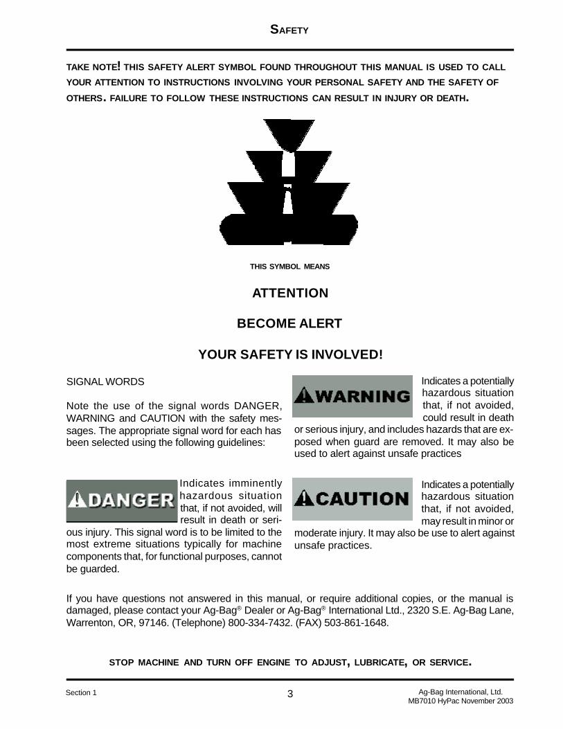
TAKE NOTE! THIS SAFETY ALERT SYMBOL FOUND THROUGHOUT THIS MANUAL IS USED TO CALL
YOUR ATTENTION TO INSTRUCTIONS INVOLVING YOUR PERSONAL SAFETY AND THE SAFETY OF
OTHERS. FAILURE TO FOLLOW THESE INSTRUCTIONS CAN RESULT IN INJURY OR DEATH.
THIS SYMBOL MEANS
ATTENTION
BECOME ALERT
YOUR SAFETY IS INVOLVED!
Indicates imminentlyhazardous situationthat, if not avoided, willresult in death or seri-
ous injury. This signal word is to be limited to themost extreme situations typically for machinecomponents that, for functional purposes, cannotbe guarded.
Indicates a potentiallyhazardous situationthat, if not avoided,may result in minor or
moderate injury. It may also be use to alert againstunsafe practices.
SIGNAL WORDS
Note the use of the signal words DANGER,WARNING and CAUTION with the safety mes-sages. The appropriate signal word for each hasbeen selected using the following guidelines:
Indicates a potentiallyhazardous situationthat, if not avoided,could result in death
or serious injury, and includes hazards that are ex-posed when guard are removed. It may also beused to alert against unsafe practices
If you have questions not answered in this manual, or require additional copies, or the manual isdamaged, please contact your Ag-Bag® Dealer or Ag-Bag® International Ltd., 2320 S.E. Ag-Bag Lane,Warrenton, OR, 97146. (Telephone) 800-334-7432. (FAX) 503-861-1648.
SAFETY
4
STOP MACHINE AND TURN OFF ENGINE TO ADJUST, LUBRICATE, OR SERVICE.
Ag-Bag International, Ltd.MB7010 HyPac November 2003
Section 1
EQUIPMENT SAFETY GUIDELINES
Safety of the operator is one of the main concerns in designing and developing a new piece ofequipment. Designers and manufacturers build in as many safety features as possible. How-ever, every year many accidents occur which could have been avoided by a few seconds ofthought and a more careful approach to handling equipment. You, the operator, can avoidmany accidents by observing the following precautions in this section. To avoid personalinjury, study the following precautions and insist those working with you or for you follow them.
In order to provide a better view, certain photographs or illustrations in this manual may showan assembly with a safety shield removed. However, equipment should never be operated inthis condition. Keep all shields in place. If shield removal becomes necessary for repairs,replace the shield prior to use.
Replace any CAUTION, WARNING, DANGER or NOTICE label that is not readable or is miss-ing.
Do not attempt to operate this equipment under the influence of drugs or alcohol.
Review the safety instructions with all users annually.
This equipment is dangerous to children and persons unfamiliar with its operation. The opera-tor should be a responsible adult familiar with farm machinery and trained in this equipment’soperation. Do not allow persons to operate or assemble this unit until they have readthis manual and have developed a through understanding of the safety precautionsand how it works.
Do not paint over, remove or deface any safety signs or warning labels on your equipment.Observe all safety signs and practice the instructions on them.
Never exceed the limits of a piece of machinery. If its ability to do a job, or to do so safely, is inquestion - DON’T TRY IT.
LIGHTING AND MARKING
It is the responsibility of the operator to know the lighting and marking requirements of the localhighway authorities and to install and maintain the equipment to provide compliance with theregulations. Add extra lights when transporting at night or during periods of limited visibility.

SAFETY
5
STOP MACHINE AND TURN OFF ENGINE TO ADJUST, LUBRICATE, OR SERVICE.
Ag-Bag International, Ltd.MB7010 HyPac November 2003
Section 1
SAFETY SIGN CARE:
Keep safety signs clean and legible at all times.
• Replace safety signs that are missing or have become illegible
• Replaced parts that displayed a safety sign should also display the current sign.
• Safety signs are available from your authorized Ag-Bag® Dealer or Ag-Bag Interna-tional, Ltd.
HOW TO INSTALL SAFETY SIGNS:
• Be sure that the installation area is clean and dry.
• Decide on the exact position before you remove the backing paper.
• Remove the smallest portion of the split backing paper.
• Align the decal over the specified area and carefully press the small portion with theexposed sticky backing in place.
• Slowly peel back the remaining paper and carefully smooth the remaining portion ofthe decal in place.
• Small air pockets can be pierced with a pin and smoothed out using the piece of decalbacking paper.
TIRE SAFETY:
• Failure to follow proper procedures when mounting a tire on a wheel or rim can pro-duce an explosion which may result in serious injury or death.
• Do not attempt to mount a tire unless you have the proper equipment and experienceto do the job.
• Inflating or servicing tires can be dangerous. Whenever possible, trained personnelshould be called to service and/or mount tires.
• Always order and install tires and wheels with appropriate capacity to meet or exceedthe anticipated weight to be placed on the equipment.

SAFETY
6
STOP MACHINE AND TURN OFF ENGINE TO ADJUST, LUBRICATE, OR SERVICE.
Ag-Bag International, Ltd.MB7010 HyPac November 2003
Section 1
REMEMBER:
Your best assurance against accidents is a careful and responsible operator. If thereis any portion of this manual or function you do not understand, contact your localauthorized Ag-Bag® Dealer or Ag-Bag International, Ltd.
BEFORE OPERATION:
• Carefully study and understand this manual.
• Do not wear loose-fitting clothing which may catch in moving parts.
• Always wear protective clothing and substantial shoes.
• It is recommended that suitable protective hearing and (eye protection) sight protec-tors be worn.
• Keep wheel lug nuts or bolts tightened to specified torque.
• Assure that agricultural implement tires are inflated evenly.
• Give the unit a visual inspection for any loose bolts, worn parts or cracked welds, andmake necessary repairs. Follow the maintenance safety instructions included in this manual.
• Be sure that there are no tools lying on or in the equipment.
• Do not use the unit until you are sure that the area is clear, especially children andanimals.
• Don’t hurry the learning process or take the unit for granted. Ease into it and becomefamiliar with your new equipment.
• Practice operation of your equipment and its attachments. Completely familiarize yourselfand other operators with its operation before using.
• Move tractor to the widest recommended settings to increase stability.
• Securely attach to towing unit. Use a high strength, appropriately sized hitch pin with amechanical retainer and attach safety chain.
• Do not allow anyone to stand between the tongue or hitch and the towing vehicle whenbacking up to the equipment.
SAFETY
7
STOP MACHINE AND TURN OFF ENGINE TO ADJUST, LUBRICATE, OR SERVICE.
Ag-Bag International, Ltd.MB7010 HyPac November 2003
Section 1
DURING OPERATION:
• SAFETY CHAIN - if equipment is going to be transported on a public highway, a safetychain should be obtained and installed. Always follow state and local regulations regarding asafety chain and auxiliary lighting when towing farm equipment on a public highway. Be sure tocheck with local law enforcement agencies for your own particular regulations. Only a safetychain (not and elastic or nylon/plastic tow strap) should be used to retain the connectionbetween the towing and towed machine in the event of separation of the primary attachingsystem.
• Install the safety chain by crossing the chains under the tongue and secure to the drawbar cage or hitch or bumper frame.
• Beware of bystanders, particularly children! Always look around to make sure that itis safe to start the engine of the towing vehicle or move the unit. This is particularly import withhigher noise levels and quiet cabs, as you may not hear people.
• NO PASSENGERS ALLOWED - Do not carry passengers anywhere on, or in, thetractor or equipment, except as required for operations.
• Keep hands and clothing clear of moving parts.
• Do not clean, lubricate or adjust your equipment while it is operating.
• When halting operation, even periodically, set the tractor or towing vehicle brakes,disengage the PTO, shut off the engine and remove the ignition key.
• Pick the levelest possible route when transporting across fields. Avoid the edges ofditches or gullies and steep hillsides.
• Maneuver the tractor or towing vehicle at safe speeds.
• Avoid overhead wires or other obstacles. Contact with overhead lines could causeserious injury or death.
• Allow for unit length when making turns.
• Do not walk or work under raised components or attachments unless securely posi-tioned and blocked.
• Keep all bystanders, pets and livestock clear of the work area.

SAFETY
8
STOP MACHINE AND TURN OFF ENGINE TO ADJUST, LUBRICATE, OR SERVICE.
Ag-Bag International, Ltd.MB7010 HyPac November 2003
Section 1
FOLLOWING OPERATION:
• Following operation, or when unhitching, stop the tractor, set the brakes, disengagethe PTO and all power drives, shut off the engine and remove the ignition keys.
• Store the unit in an area away from human activity.
• Do not permit children to play on or around the stored unit.
• Make sure all parked machines are on a hard, level surface and engage all safetydevices.
• Wheel chocks may be needed to prevent unit from rolling.
HIGHWAY AND TRANSPORT OPERATIONS:
• Adopt safe driving practices:
• Keep the brake pedal latched together at all times. NEVER USE INDEPEN-DENT BRAKING WITH MACHINE IN TOW AS LOSS OF CONTROL AND/ORUPSET OF UNIT CAN RESULT.
• Always drive at a safe speed relative to local conditions and ensure that yourspeed is low enough for an emergency stop to be safe and secure. Keep speed to aminimum.
• Reduce speed prior to turns to avoid the risk of overturning.
• Avoid sudden uphill turns on steep slopes.
• Always keep the tractor in gear to provide engine braking when going downhill.Do not coast.
• Do not drink and drive!
• Comply with state and local laws governing highway safety and movement offarm machinery on public roads.
• Use approved accessory lighting, flags, and necessary warning devices toprotect operators of other vehicles on the highway during daylight and nighttime trans-port. Various safety light and devices are available from you Ag-Bag® Dealer.
SAFETY
9
STOP MACHINE AND TURN OFF ENGINE TO ADJUST, LUBRICATE, OR SERVICE.
Ag-Bag International, Ltd.MB7010 HyPac November 2003
Section 1
• The use of a flashing amber light is acceptable in most localities. However, somelocalities prohibit their use. Local laws should be checked for all highway lighting and markingrequirements.
• When driving the tractor and equipment on the road or highway at night or during theday, use flashing amber warning lights and a slow moving vehicle (SMV) identification em-blem.
• Plan your route to avoid heavy traffic.
• Be a safe and courteous driver. Always yield to oncoming traffic in all situations, in-cluding narrow bridges, intersections, etc.
• Be observant of bridge loading ratings. Do not cross bridges rated lower than thegross weight at which you are operating.
• Watch for obstructions overhead and to the side while transporting.
• Always operate equipment in a position to provide maximum visibility at all times.
PERFORMING MAINTENANCE:
• Good maintenance is your responsibility. Poor maintenance is an invitation to trouble.
• Make sure there is plenty of ventilation. Never operate the engine of the towing vehiclein a closed building. The exhaust fumes may cause asphyxiation.
• Before working on this machine, stop the towing vehicle, set the brakes, disengagethe PTO and all power drivers, shut off the engine and remove the ignition keys.
• Be certain all moving parts on the machine have come to a complete stop beforeattempting to perform maintenance.
• Always use a safety support and block the wheels. Never use a jack to support themachine.
• Always use the proper tools or equipment for the job at hand.
• Use extreme caution when making adjustments.
• Follow the torque chart in this manual when tightening bolts and nuts.

SAFETY
10
STOP MACHINE AND TURN OFF ENGINE TO ADJUST, LUBRICATE, OR SERVICE.
Ag-Bag International, Ltd.MB7010 HyPac November 2003
Section 1
• Never use your hands to locate a hydraulic leak on attachments. Use a small piece of card-board or wood. Hydraulic fluid escaping under pressure can penetrate the skin.
• When disconnecting hydraulic lines. Shut off hydraulic supply and relieve all hydraulic pres-sure.
• Openings in the skin and minor cuts are susceptible to infection from hydraulic fluid. If injuredby escaping hydraulic fluid, see a doctor at once. Gangrene can result. Without immediatemedical treatment, serious infection and reactions can occur.
• Replace all shields and guards after servicing and before moving.
• After servicing, be sure all tools, parts and service equipment are removed.
• Do not allow grease or oil to build up on any step or platform.
• Never replace hex bolts with less than grade five bolts unless otherwise specified. Refer to bolttorque chart for head identification marking.
• Where replacement parts are necessary for periodic maintenance and servicing, genuine fac-tory replacement parts must be used to restore your equipment to original specifications. Ag-BagInternational will not claim responsibility for use of unapproved parts and/or accessories and otherdamages as a result of their use.
• If equipment has been altered in any way from original design, Ag-Bag International, Ltd. doesnot accept any liability for injury or warranty.
• A fire extinguisher and first aid kit should be kept readily accessible while performing mainte-nance on this equipment.
SAFETY
11
STOP MACHINE AND TURN OFF ENGINE TO ADJUST, LUBRICATE, OR SERVICE.
Ag-Bag International, Ltd.MB7010 HyPac November 2003
Section 1
This section of the manual presents the Labels used on the Ag-Bagger®. Also presented are otherinformation that you should know in order to operate the Ag-Bagger® in a safe manner. Unless other-wise noted the decals shown are the actual decals used on the machine.
DANGER LABELS
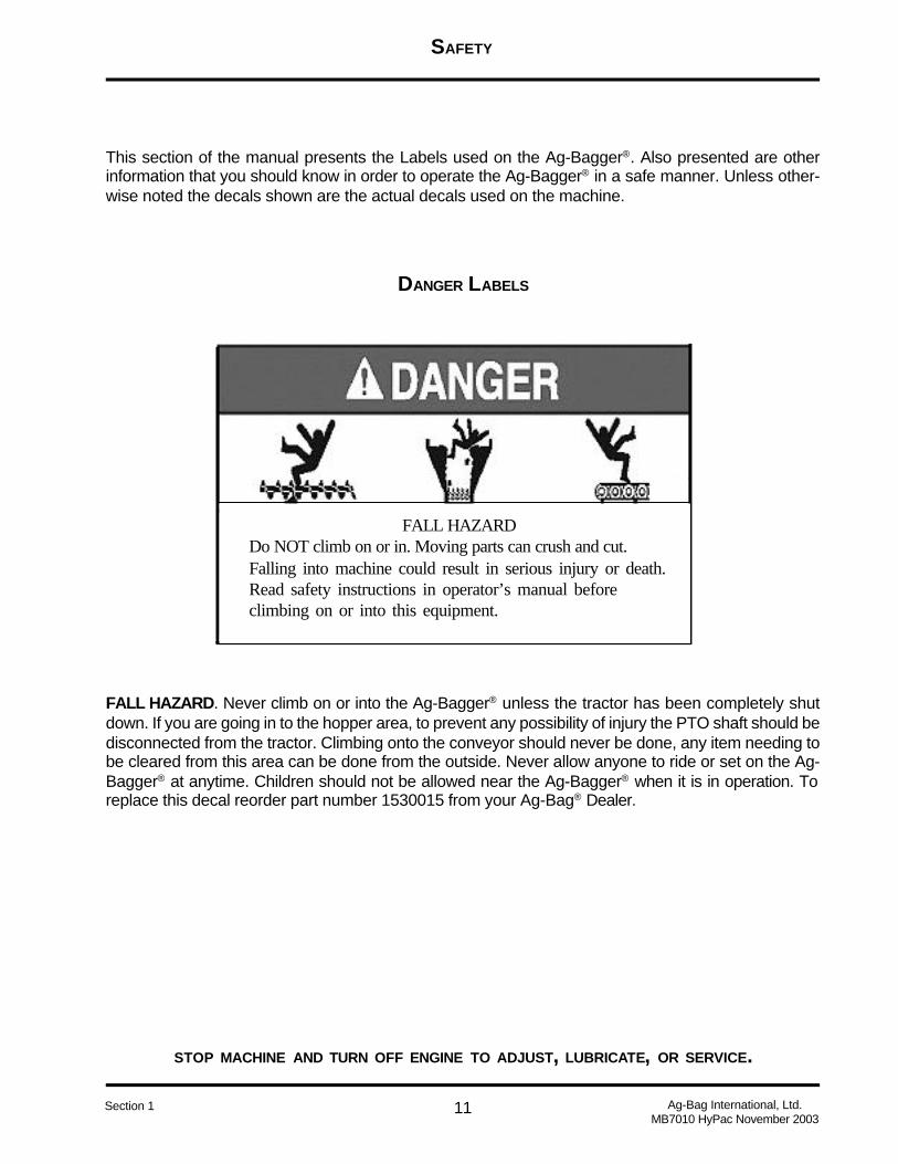
FALL HAZARD. Never climb on or into the Ag-Bagger® unless the tractor has been completely shutdown. If you are going in to the hopper area, to prevent any possibility of injury the PTO shaft should bedisconnected from the tractor. Climbing onto the conveyor should never be done, any item needing tobe cleared from this area can be done from the outside. Never allow anyone to ride or set on the Ag-Bagger® at anytime. Children should not be allowed near the Ag-Bagger® when it is in operation. Toreplace this decal reorder part number 1530015 from your Ag-Bag® Dealer.
FALL HAZARDDo NOT climb on or in. Moving parts can crush and cut.Falling into machine could result in serious injury or death.Read safety instructions in operator’s manual beforeclimbing on or into this equipment.
SAFETY
12
STOP MACHINE AND TURN OFF ENGINE TO ADJUST, LUBRICATE, OR SERVICE.
Ag-Bag International, Ltd.MB7010 HyPac November 2003
Section 1
WARNING LABELS
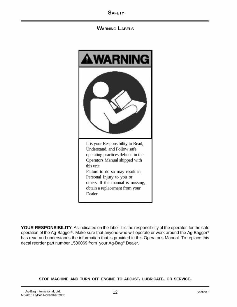
It is your Responsibility to Read,Understand, and Follow safeoperating practices defined in theOperators Manual shipped withthis unit.Failure to do so may result inPersonal Injury to you orothers. If the manual is missing,obtain a replacement from yourDealer.
YOUR RESPONSIBILITY. As indicated on the label it is the responsibility of the operator for the safeoperation of the Ag-Bagger®. Make sure that anyone who will operate or work around the Ag-Bagger®
has read and understands the information that is provided in this Operator’s Manual. To replace thisdecal reorder part number 1530069 from your Ag-Bag® Dealer.

SAFETY
13
STOP MACHINE AND TURN OFF ENGINE TO ADJUST, LUBRICATE, OR SERVICE.
Ag-Bag International, Ltd.MB7010 HyPac November 2003
Section 1
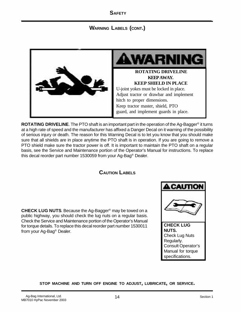
WARNING LABELS (CONT.)
SKIN INJECTION HAZARD.Avoid contact with highpressure fluid.BEFORE SERVICING:Relieve stored hydraulic pressure.Failure to follow this warning canresult in serious injury.
SKIN INJECTION HAZARD. Hydraulic oils and fluid under high pressure can be injected under theskin. The oil/fluid can cause serious illness. Always shut down the tractor and relieve all stored pres-sure on the hoses before servicing. Never run your hand over a hydraulic hose you suspect has a leak.To replace this decal reorder part number 1530127 from your Ag-Bag® Dealer.
KEEP SHIELDSIN PLACE.Pinch hazard exists.DO NOT operate equipmentunless shields are in place
KEEP SHIELDS IN PLACE. There are numerous shields located on the Ag-Bagger® they are placedto keep the operator safe from serious injury. Never remove a shield while the Ag-Bagger® is in opera-tion. Make sure the tractor has been shut off before removing any shield, and that the shield has beenreplaced before operation resumes. To replace this decal reorder part number 1530038 from your Ag-Bag® Dealer.
SAFETY
14
STOP MACHINE AND TURN OFF ENGINE TO ADJUST, LUBRICATE, OR SERVICE.
Ag-Bag International, Ltd.MB7010 HyPac November 2003
Section 1
ROTATING DRIVELINEKEEP AWAY.
KEEP SHIELD IN PLACEU-joint yokes must be locked in place.Adjust tractor or drawbar and implementhitch to proper dimensions.Keep tractor master, shield, PTOguard, and implement guards in place.
WARNING LABELS (CONT.)
ROTATING DRIVELINE. The PTO shaft is an important part in the operation of the Ag-Bagger® it turnsat a high rate of speed and the manufacturer has affixed a Danger Decal on it warning of the possibilityof serious injury or death. The reason for this Warning Decal is to let you know that you should makesure that all shields are in place anytime the PTO shaft is in operation. If you are going to remove aPTO shield make sure the tractor power is off. It is important to maintain the PTO shaft on a regularbasis, see the Service and Maintenance portion of the Operator’s Manual for instructions. To replacethis decal reorder part number 1530059 from your Ag-Bag® Dealer.
CAUTION LABELS
CHECK LUGNUTS.Check Lug NutsRegularly.Consult Operator’sManual for torquespecifications.
CHECK LUG NUTS. Because the Ag-Bagger® may be towed on apublic highway, you should check the lug nuts on a regular basis.Check the Service and Maintenance portion of the Operator’s Manualfor torque details. To replace this decal reorder part number 1530011from your Ag-Bag® Dealer.

SAFETY
15
STOP MACHINE AND TURN OFF ENGINE TO ADJUST, LUBRICATE, OR SERVICE.
Ag-Bag International, Ltd.MB7010 HyPac November 2003
Section 1
CAUTION LABELS (CONT.)
MAXIMUM TOWING SPEED. Although you can tow the Ag-Bag-ger on the open highway do not exceed 25 mile per hour. It shouldbe remembered that the Ag-Bagger® does not have brakes, alsothe wheels and axles are not bolted to the frame but are held inplace by a pin and hair pin. Under no circumstances should you towthe Ag-Bagger® while the wheels are in the bagging position. Makesure you read and understand the section on preparing the Ag-Bag-ger for transit in the Operator’s Manual. The PB6000 has its wheelsfixed in place, this requires that it be towed in the bagging positionand should be towed a lower speed. To replace this decal reorderpart number 1530041 from your Ag-Bag® Dealer.
NOTICE LABELS
Grease rotorbearing 4 pumpsper bag.
GREASE ROTOR BEARING. The Ag-Bagger® is equipped with two Rotor Bearing Grease Whips.The zerk fittings are located on the frame on either side of the tunnel. For the best results with your Ag-Bagger® use the type grease recommended in the Service and Maintenance portion of the Operator’sManual. To replace this decal reorder part number 1530096 from your Ag-Bag® Dealer.

SAFETY
16
STOP MACHINE AND TURN OFF ENGINE TO ADJUST, LUBRICATE, OR SERVICE.
Ag-Bag International, Ltd.MB7010 HyPac November 2003
Section 1
NOTICE LABELS (CONT.)
HYDRAULICOIL ONLY.Use only hydraulicoil with viscosityrecommended intheOperator’s Manualfor this machine
HYDRAULIC OIL ONLY. The Operator’s Manual makes recom-mendations for the correct viscosity of hydraulic oil to be used inyour Ag-Bagger® hydraulic system. To keep you warranty valid useonly the viscosity listed in the Service and Maintenance section ofthe Operator’s Manual. To replace this decal reorder part number1530028 from your Ag-Bag® Dealer.
TRACTOR TO
BE IN NEUTRAL
AND BRAKES
OFF WHILE
OPERATING
BAGGER.
TRACTOR TO BE IN NEUTRAL . During the process of baggingthe tractor is pushed forward as the bag fills. In order to minimizedamage to the Ag-Bagger®, your tractor, and the correct compac-tion of the product being bagged, it is important the tractor be inneutral and all brakes be released before starting to bag. To replacethis decal reorder part number 1530065 from your Ag-Bag® Dealer.
SAFETY
17
STOP MACHINE AND TURN OFF ENGINE TO ADJUST, LUBRICATE, OR SERVICE.
Ag-Bag International, Ltd.MB7010 HyPac November 2003
Section 1
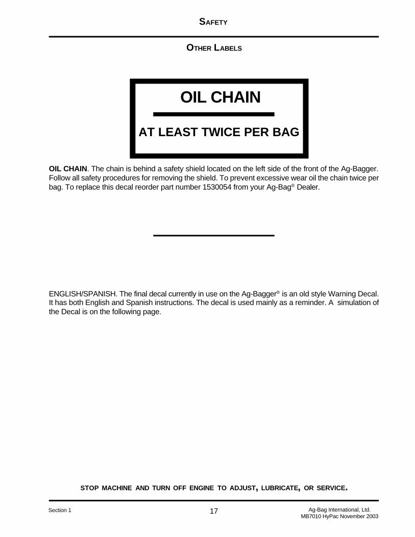
OTHER LABELS
OIL CHAIN
AT LEAST TWICE PER BAG
OIL CHAIN. The chain is behind a safety shield located on the left side of the front of the Ag-Bagger.Follow all safety procedures for removing the shield. To prevent excessive wear oil the chain twice perbag. To replace this decal reorder part number 1530054 from your Ag-Bag® Dealer.
ENGLISH/SPANISH. The final decal currently in use on the Ag-Bagger® is an old style Warning Decal.It has both English and Spanish instructions. The decal is used mainly as a reminder. A simulation ofthe Decal is on the following page.

SAFETY
18
STOP MACHINE AND TURN OFF ENGINE TO ADJUST, LUBRICATE, OR SERVICE.
Ag-Bag International, Ltd.MB7010 HyPac November 2003
Section 1
OTHER LABELS (CONT.)
WARNINGPRECACION
1. DO NOT reach or place any part of your body inside the hopper. NO TRATE de alcanzar o ponga ninguna parta del cuerpo adentro de la mezcladora.
2. DO NOT attempt to service, remove or unclog any material while machine is in opera-tion. NO TRATE de reparar, remover, o destapar material cuando la maquina esta enoperacion.
3. DO NOT climb or ride on machine during operation or transport. NO TREPE o monte la maquina cuando esta en operacion or transportando.
4. Make sure everyone is clear of machine BEFORE STARTING ENGINE OR ENGAG-ING POWER. KEEP CHILDREN AWAY AT ALL TIMES. Haga seguro que nadie este en o ALREDEDOR DE LA MAQUINA ANTES QUE ELMOTOR ARRANQUE, MANTEGA NINOS LEJOS DE LA MAQUINA.
5. DO NOT stand behind backstop net or near cables under tension. NO se pare detras de la malla o cerca de cables en tension.
6. STAY CLEAR of hoses under pressure. MANTENGASE LEJOS de las mangas a presion.
7. Keep all SHIELDS IN PLACE. Mantenga los ESCUDOS EN SU PROPIO LUGAR.
8. Keep HANDS, FEET AND CLOTHING AWAY FROM INTAKE AREA AND ALL OTHERMOVING PARTS OF MACHINE. Mantenga las MANOS, PIES, Y ROPA FUERA DEL AREADE ADMISION.
9. Think SAFETY AND USE CAUTION in entire operation area. SEA PRECAVIDOY SEA CUIDADOSO en la area de operacion.
SAFETY
19
STOP MACHINE AND TURN OFF ENGINE TO ADJUST, LUBRICATE, OR SERVICE.
Ag-Bag International, Ltd.MB7010 HyPac November 2003
Section 1
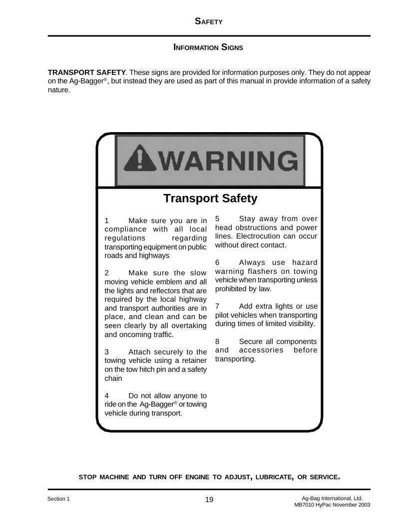
INFORMATION SIGNS
TRANSPORT SAFETY. These signs are provided for information purposes only. They do not appearon the Ag-Bagger®, but instead they are used as part of this manual in provide information of a safetynature.
1 Make sure you are incompliance with all localregulations regardingtransporting equipment on publicroads and highways
2 Make sure the slowmoving vehicle emblem and allthe lights and reflectors that arerequired by the local highwayand transport authorities are inplace, and clean and can beseen clearly by all overtakingand oncoming traffic.
3 Attach securely to thetowing vehicle using a retaineron the tow hitch pin and a safetychain
4 Do not allow anyone toride on the Ag-Bagger® or towingvehicle during transport.
Transport Safety
5 Stay away from overhead obstructions and powerlines. Electrocution can occurwithout direct contact.
6 Always use hazardwarning flashers on towingvehicle when transporting unlessprohibited by law.
7 Add extra lights or usepilot vehicles when transportingduring times of limited visibility.
8 Secure all componentsand accessories beforetransporting.

SAFETY
20
STOP MACHINE AND TURN OFF ENGINE TO ADJUST, LUBRICATE, OR SERVICE.
Ag-Bag International, Ltd.MB7010 HyPac November 2003
Section 1
INFORMATION SIGNS (CONT.)
SILAGE GASES - The ensiling process inside the bag may produce gases. Do not breath gasesexpelled from the bag. These gases may contain various forms of nitric fumes that can be harmful toyour lungs. If enough fumes are inhaled they can be fatal.
SERVICING THE AG-BAGGER® - Do not attempt to perform service or maintenance to the Ag-Bag-ger® or PTO shaft unless the tractor has been turned off and all moving parts have stopped.
Bodily injury or death may occur. Prior to servicingthe Ag-Bagger® turn of the tractor and wait for allmoving parts to stop.
NOISE - Long-term exposure to loud noise can impair and cause loss of hearing. Use hearing protec-tion.

SAFETY
21
STOP MACHINE AND TURN OFF ENGINE TO ADJUST, LUBRICATE, OR SERVICE.
Ag-Bag International, Ltd.MB7010 HyPac November 2003
Section 1
INFORMATION SIGNS (CONT.)
NO SMOKING - Handle fuel with care while fueling. Fuel is extremely flammable and explosive.
BATTERY - Handle battery with caution. Sulfuric acid in the battery’s electrolyte is strong enough toburn skin, cause blindness if splashed in eye’s and damage clothing.
CABLES - Always wear protective gloves when handling cables for any reason. Serious inju-ries can occur.

SAFETY
22
STOP MACHINE AND TURN OFF ENGINE TO ADJUST, LUBRICATE, OR SERVICE.
Ag-Bag International, Ltd.MB7010 HyPac November 2003
Section 1
Index
B
BATTERY 21
L
Labels - CautionCaution Labels 14CHECK LUG NUTS 14MAXIMUM TOWING SPEED 15
Labels - DangerDanger Labels 11FALL HAZARD 11
Labels - Information OnlyBATTERY 21CABLES 21Information Signs 19NO SMOKING 21Noise 20Servicing the Ag-Bagger® 20Silage Gases 20TRANSPORT SAFETY 19
Labels - NoticeGREASE ROTOR BEARING 15HYDRAULIC OIL ONLY 16Notice Labels 15TRACTOR TO BE IN NEUTRAL 16
Labels - OtherENGLISH/SPANISH 17OIL CHAIN 17Other Labels 17
Labels - WarningKEEP SHIELDS IN PLACE 13ROTATING DRIVELINE 14SKIN INJECTION HAZARD 13Warning Labels 12YOUR RESPONSIBILITY 12
N
NO SMOKING 21
S
Safety InstructionsBEFORE OPERATION: 6DURING OPERATION: 7EQUIPMENT SAFETY GUIDELINES 4FOLLOWING OPERATION: 8How to Install Safety Signs: 5LIGHTING AND MARKING 4PERFORMING MAINTENANCE: 9REMEMBER 6SAFETY SIGN CARE: 5TIRE SAFETY: 5TRANSPORT OPERATIONS 8
SIGNAL WORDS 3Signal Words
CAUTION 3DANGER 3WARNING 3

MACHINE OVERVIEW
1 Ag-Bag International, Ltd.MB7010 HyPac November 2003
Section 2
The machine overview section shows and identifies the location of many of the commonlyused features of the Ag-Bagger®. The pictures should be used as a reference to quickly locatethe different options and features of your Ag-Bagger®. Also the terms Front, Rear, Right-Side,and Left-Side are used else where in this manual for you convenience.
AG-BAGGER® MODEL
MB7010 HyPac

MACHINE OVERVIEW
2Ag-Bag International, Ltd.MB7010 HyPac November 2003
Section 2
Table of Contents
FRONT VIEW ....................................................................................................................................... 3
REAR VIEW ......................................................................................................................................... 4
RIGHT SIDE VIEW ............................................................................................................................... 5
LEFT SIDE VIEW ................................................................................................................................. 6
INDEX................................................................................................................................................... 7
MACHINE OVERVIEW
3 Ag-Bag International, Ltd.MB7010 HyPac November 2003
Section 2
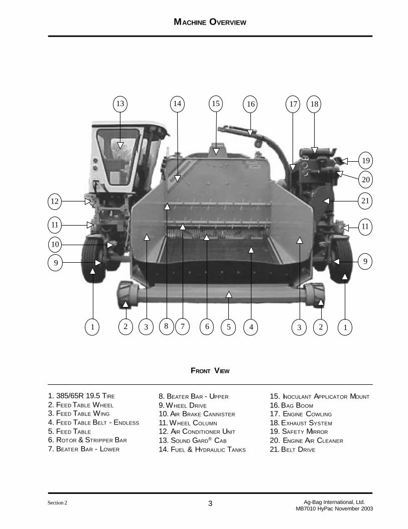
FRONT VIEW
11 2 23 345678
9
10
11
12
13 14 15 16 17 18
19
20
21
11
9
1. 385/65R 19.5 TIRE
2. FEED TABLE WHEEL
3. FEED TABLE W ING
4. FEED TABLE BELT - ENDLESS
5. FEED TABLE
6. ROTOR & STRIPPER BAR
7. BEATER BAR - LOWER
8. BEATER BAR - UPPER
9. WHEEL DRIVE
10. AIR BRAKE CANNISTER
11. WHEEL COLUMN
12. AIR CONDITIONER UNIT
13. SOUND GARD® CAB
14. FUEL & HYDRAULIC TANKS
15. INOCULANT APPLICATOR MOUNT
16. BAG BOOM
17. ENGINE COWLING
18. EXHAUST SYSTEM
19. SAFETY MIRROR
20. ENGINE AIR CLEANER
21. BELT DRIVE

MACHINE OVERVIEW
4Ag-Bag International, Ltd.MB7010 HyPac November 2003
Section 2
REAR VIEW
11 2345678
9
10
11
12 13 14 15 16
17
18
1. 385/65R 19.5 TIRE
2. BAG PAN
3. TUNNEL FLOOR
4. ROTOR & STRIPPER BAR
5. ANCHOR SUPPORT
6. ANCHOR
7. 10’ TUNNEL
8. WHEEL DRIVE
9. WHEEL COLUMN
10. ENGINE MOUNTING FRAME
11. RADIATOR SCREEN
12. ENGINE EXHAUST
13. BAG BOOM
14. BAG CRADLE
15. 10’ TUNNEL EXTENSION
16. SOUND GARD® CAB
17. OPERATOR’S PLATFORM
18. ACCESS LADDER

MACHINE OVERVIEW
5 Ag-Bag International, Ltd.MB7010 HyPac November 2003
Section 2
RIGHT SIDE V IEW
121345
6 7 8 9 10
11
12
1. 385/65R 19.5 TIRE
2. HYDRAULIC LIFT JACK
3. FEED TABLE
4. FEED TABLE W ING
5. FEED TABLE WHEEL
6. BELT DRIVE
7. AIR CHAMBER
8. SAFETY MIRROR
9. ENGINE AIR CLEANER
10. ENGINE EXHAUST
11. BAG BOOM
12. RADIATOR SCREEN
MACHINE OVERVIEW
6Ag-Bag International, Ltd.MB7010 HyPac November 2003
Section 2
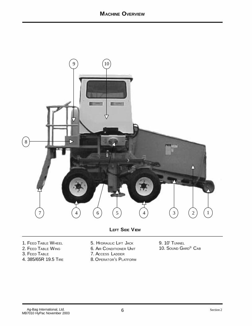
LEFT SIDE V IEW
12344 567
9 10
8
1. FEED TABLE WHEEL
2. FEED TABLE W ING
3. FEED TABLE
4. 385/65R 19.5 TIRE
5. HYDRAULIC LIFT JACK
6. AIR CONDITIONER UNIT
7. ACCESS LADDER
8. OPERATOR’S PLATFORM
9. 10’ TUNNEL
10. SOUND GARD® CAB
MACHINE OVERVIEW
7 Ag-Bag International, Ltd.MB7010 HyPac November 2003
Section 2
Index
Symbols
10’ Tunnel 4, 610’ Tunnel Extension 4385/65R 19.5 Tire 3, 4, 5, 6
A
Access Ladder 4, 6Air Brake Cannister 3Air Chamber 5Air Conditioner Unit 3, 6Anchor 4Anchor Support 4
B
Bag Boom 3, 4, 5Bag Cradle 4Bag Pan 4Beater Bar - Lower 3Beater Bar - Upper 3Belt Drive 3, 5
E
Engine Air Cleaner 3, 5Engine Cowling 3Engine Exhaust 4, 5Engine Mounting Frame 4Exhaust System 3
F
Feed Table 3, 5, 6Feed Table Belt - Endless 3Feed Table Wheel 3, 5, 6Feed Table Wing 3, 5, 6Front View 3Fuel & Hydraulic Tanks 3
H
Hydraulic Lift Jack 5, 6
I
Inoculant Applicator Mount 3
L
Left Side View 6
O
Operator’s Platform 4, 6
R
Radiator Screen 4, 5Rear View 4Right Side View 5Rotor & Stripper Bar 3, 4
S
Safety Mirror 3, 5Sound Gard® Cab 3, 4, 6
T
Tunnel Floor 4
W
Wheel Column 3, 4Wheel Drive 3, 4
FEATURES AND CONTROLS
1 Ag-Bag International, Ltd.MB7010 HyPac November 2003
Section 3
AG-BAGGER® MODEL
MB7010 HyPac
FEATURES AND CONTROLS
2Ag-Bag International, Ltd.MB7010 HyPac November 2003
Section 3
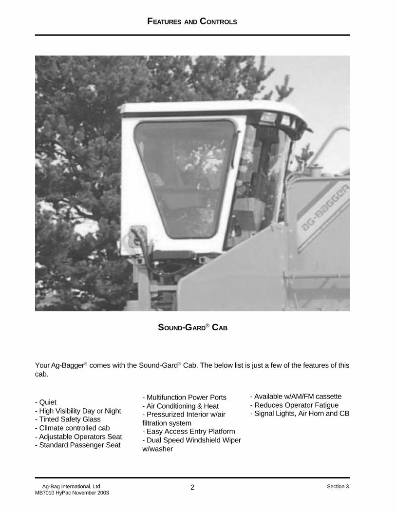
SOUND-GARD® CAB
Your Ag-Bagger® comes with the Sound-Gard® Cab. The below list is just a few of the features of thiscab.
- Quiet- High Visibility Day or Night- Tinted Safety Glass- Climate controlled cab- Adjustable Operators Seat- Standard Passenger Seat
- Multifunction Power Ports- Air Conditioning & Heat- Pressurized Interior w/airfiltration system- Easy Access Entry Platform- Dual Speed Windshield Wiperw/washer
- Available w/AM/FM cassette- Reduces Operator Fatigue- Signal Lights, Air Horn and CB
FEATURES AND CONTROLS
3 Ag-Bag International, Ltd.MB7010 HyPac November 2003
Section 3
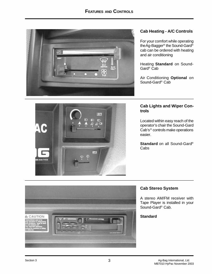
Cab Heating - A/C Controls
For your comfort while operatingthe Ag-Bagger® the Sound-Gard®
cab can be ordered with heatingand air conditioning
Heating Standard on Sound-Gard® Cab
Air Conditioning Optional onSound-Gard® Cab
Cab Lights and Wiper Con-trols
Located within easy reach of theoperator’s chair the Sound-GardCab’s® controls make operationseasier.
Standard on all Sound-Gard®
Cabs
Cab Stereo System
A stereo AM/FM receiver withTape Player is installed in yourSound-Gard® Cab.
Standard

FEATURES AND CONTROLS
4Ag-Bag International, Ltd.MB7010 HyPac November 2003
Section 3
43
21
5 6
7
8
9
10
11
12
13
14
15
16
1. Signal Lights2. Horn3. Rotor Control4. Beater Bar Direction5. Diagnostics Gauge6. Ignition Switch7. Idle Speed8. Mode Switch9. Anchor Float10. Anchor In/Out11. Feed Table Lift/Lower12. Tunnel Clean Out13. Sprayer14. Hyd Lift Jack Engine End15. Hyd Lift Jack Cab End16. Accessory Plug-In
The Arm Rest consolekeeps the bagging opera-tion of your Ag-Bagger® atyour finger tips. The elec-tric over hydraulics keepthe hydraulics out of thecab.
ARM REST CONTROLS

FEATURES AND CONTROLS
5 Ag-Bag International, Ltd.MB7010 HyPac November 2003
Section 3
CENTER CONSOLE CONTROLS
1. Air Brake Control - Engine End2. Feed Table Speed Control3. Steering - Engine End4. Wheel Drive - Engine End5. Wheel Drive - Cab End6. Steering - Cab End
7. Air Brake Control - Cab End8. Air Brake Gauge - Cab End9. Tachometer10. Tunnel Clean Out Open Light11. Air Brake Gauge - Engine End12. Fuse Panel (not visible)
2 4 5 6
10
11
12
3 71
9 8

FEATURES AND CONTROLS
6Ag-Bag International, Ltd.MB7010 HyPac November 2003
Section 3
1. DVC 102. Arm Rest Power3. Open4. Boom Light5. Console Power6. Right Pillar7. Road Lights
8. Air Conditioning9. Field Lamps10. Open11. Wiper Power12. Open13. Cab Power Outlet14. Open
Constant Power
15. Open16. Open17. Radio Memory / Dome18. Open19. Open20. Open
Fuse Panel: Located on the left side of the Center Control Console the fuse panel allows easy ac-cess to the electrical control fuses on the Ag-Bagger®
1 2
3 4
5 6
7 8
9 10
11 12
13 14
15 16
17 18
19 20
FEATURES AND CONTROLS
7 Ag-Bag International, Ltd.MB7010 HyPac November 2003
Section 3
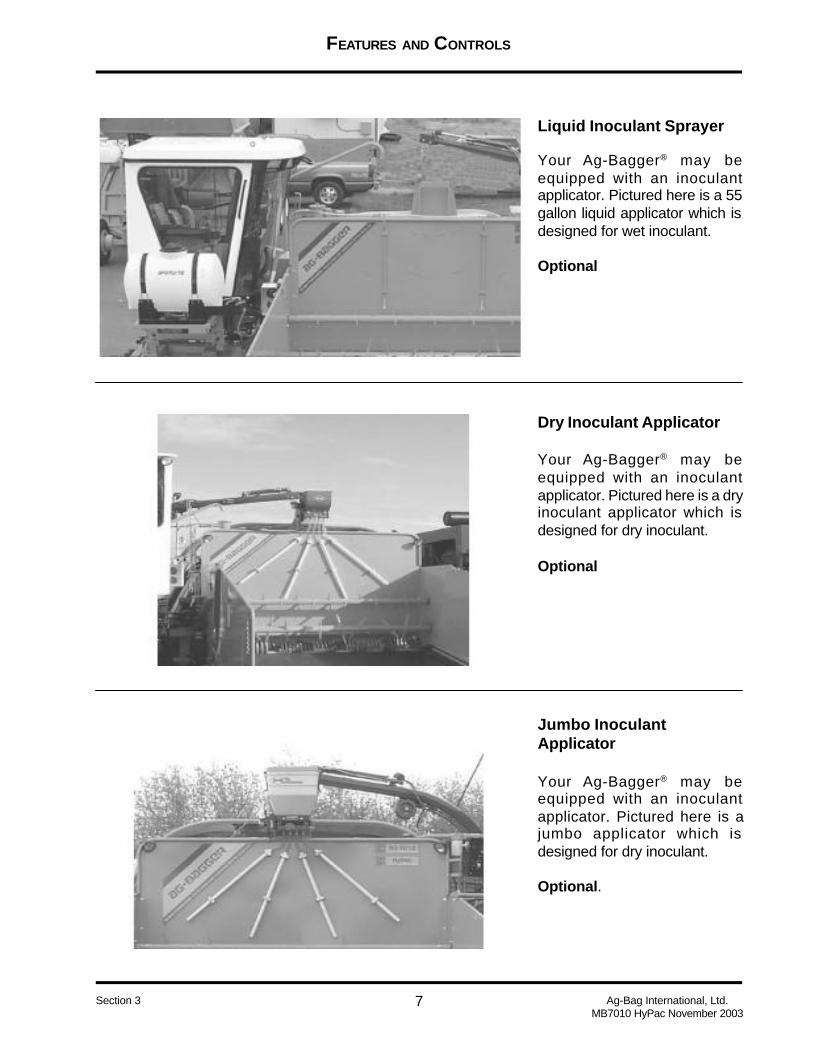
Liquid Inoculant Sprayer
Your Ag-Bagger® may beequipped with an inoculantapplicator. Pictured here is a 55gallon liquid applicator which isdesigned for wet inoculant.
Optional
Jumbo InoculantApplicator
Your Ag-Bagger® may beequipped with an inoculantapplicator. Pictured here is ajumbo applicator which isdesigned for dry inoculant.
Optional.
Dry Inoculant Applicator
Your Ag-Bagger® may beequipped with an inoculantapplicator. Pictured here is a dryinoculant applicator which isdesigned for dry inoculant.
Optional

FEATURES AND CONTROLS
8Ag-Bag International, Ltd.MB7010 HyPac November 2003
Section 3
Sweeping Hydraulic TunnelClean Out - Rear View
Viewed from the back of the tun-nel these hydraulic rams pushthe tunnel back towards the bagfor ease in cleaning product frominside the tunnel.
Standard
Sweeping Hydraulic TunnelClean Out - Front View
Viewed from the front, you cansee how the tunnel back movesaway from the rotor and will pushthe product into the bag.
Standard
Rotor
Annealed and line bored the ro-tor has a 1 inch thick wall of theseamless constructed tube.
Standard
FEATURES AND CONTROLS
9 Ag-Bag International, Ltd.MB7010 HyPac November 2003
Section 3
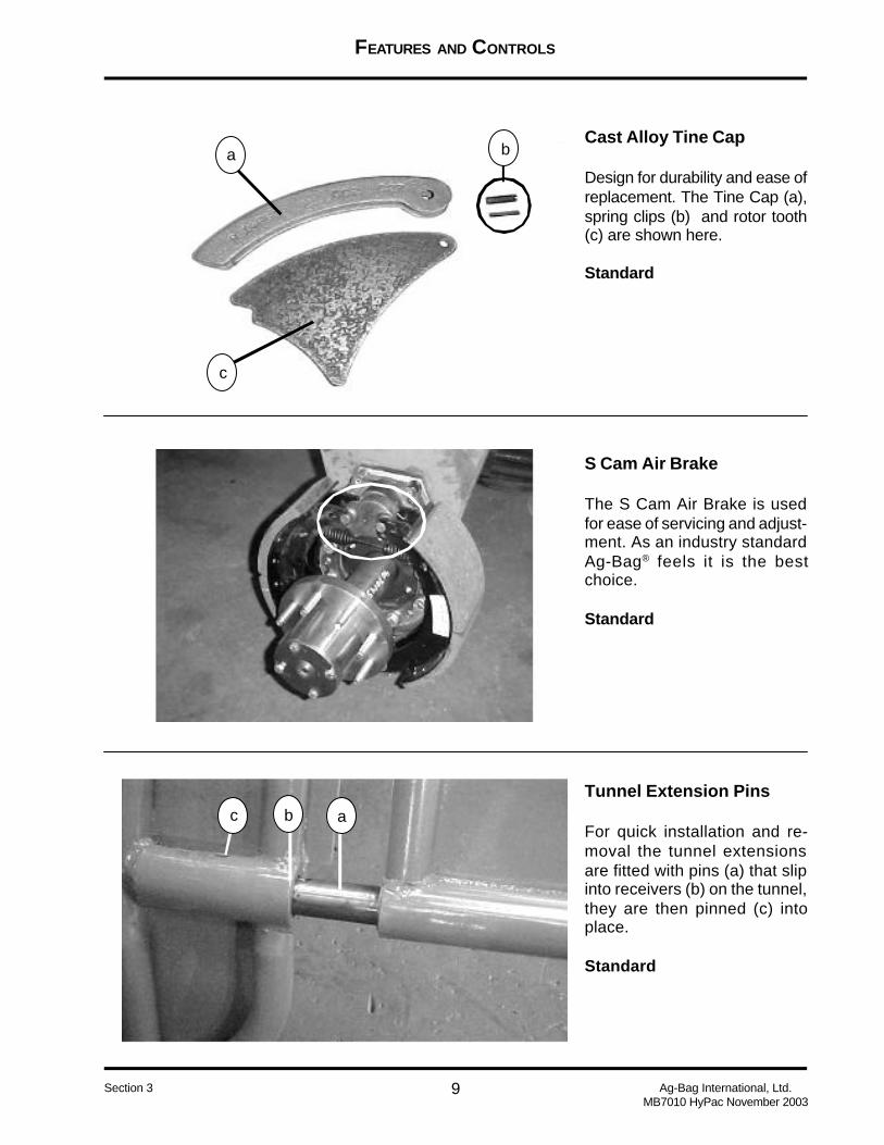
Tunnel Extension Pins
For quick installation and re-moval the tunnel extensionsare fitted with pins (a) that slipinto receivers (b) on the tunnel,they are then pinned (c) intoplace.
Standard
Cast Alloy Tine Cap
Design for durability and ease ofreplacement. The Tine Cap (a),spring clips (b) and rotor tooth(c) are shown here.
Standard
S Cam Air Brake
The S Cam Air Brake is usedfor ease of servicing and adjust-ment. As an industry standardAg-Bag® feels it is the bestchoice.
Standard
a b
c
c b a

FEATURES AND CONTROLS
10Ag-Bag International, Ltd.MB7010 HyPac November 2003
Section 3
Hydraulic Lift Jack
Positioned at either end of the Ag-Bagger® the Hydraulic Lift Jacksare used to assist in the serviceof your machine.
Standard
Platform Roller Cams
Located below the Sound-Gard®
cab and operators access plat-form these roller cams assist inthe movement of the platform forservice requirements.
Standard
Motor Platform Adjustment
Located at each corner of theengine platform these adjustingbolts are used to adjust the ten-sion of the belt drive.
Standard
FEATURES AND CONTROLS
11 Ag-Bag International, Ltd.MB7010 HyPac November 2003
Section 3
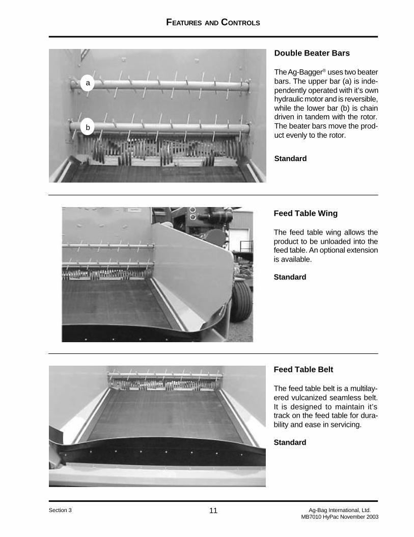
Double Beater Bars
The Ag-Bagger® uses two beaterbars. The upper bar (a) is inde-pendently operated with it’s ownhydraulic motor and is reversible,while the lower bar (b) is chaindriven in tandem with the rotor.The beater bars move the prod-uct evenly to the rotor.
a
b
Feed Table Wing
The feed table wing allows theproduct to be unloaded into thefeed table. An optional extensionis available.
Standard
Feed Table Belt
The feed table belt is a multilay-ered vulcanized seamless belt.It is designed to maintain it’strack on the feed table for dura-bility and ease in servicing.
Standard
Standard
FEATURES AND CONTROLS
12Ag-Bag International, Ltd.MB7010 HyPac November 2003
Section 3
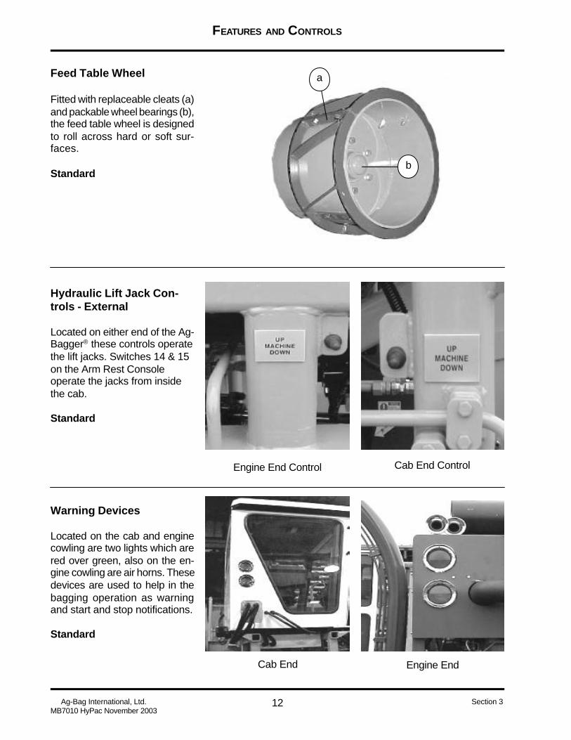
Feed Table Wheel
Fitted with replaceable cleats (a)and packable wheel bearings (b),the feed table wheel is designedto roll across hard or soft sur-faces.
Standard
Hydraulic Lift Jack Con-trols - External
Located on either end of the Ag-Bagger® these controls operatethe lift jacks. Switches 14 & 15on the Arm Rest Consoleoperate the jacks from insidethe cab.
Standard
Warning Devices
Located on the cab and enginecowling are two lights which arered over green, also on the en-gine cowling are air horns. Thesedevices are used to help in thebagging operation as warningand start and stop notifications.
Standard
a
b
Engine End Control Cab End Control
Engine EndCab End
FEATURES AND CONTROLS
13 Ag-Bag International, Ltd.MB7010 HyPac November 2003
Section 3
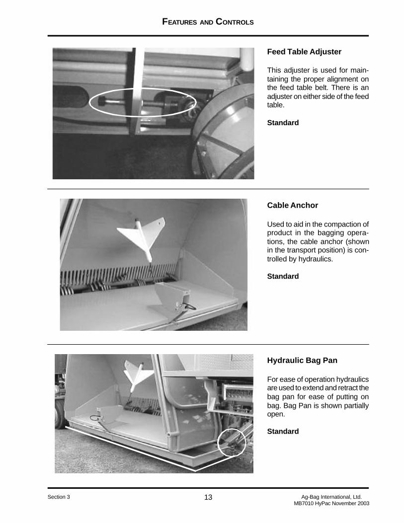
Feed Table Adjuster
This adjuster is used for main-taining the proper alignment onthe feed table belt. There is anadjuster on either side of the feedtable.
Standard
Cable Anchor
Used to aid in the compaction ofproduct in the bagging opera-tions, the cable anchor (shownin the transport position) is con-trolled by hydraulics.
Standard
Hydraulic Bag Pan
For ease of operation hydraulicsare used to extend and retract thebag pan for ease of putting onbag. Bag Pan is shown partiallyopen.
Standard
NEED NEW PICTURE
FEATURES AND CONTROLS
14Ag-Bag International, Ltd.MB7010 HyPac November 2003
Section 3
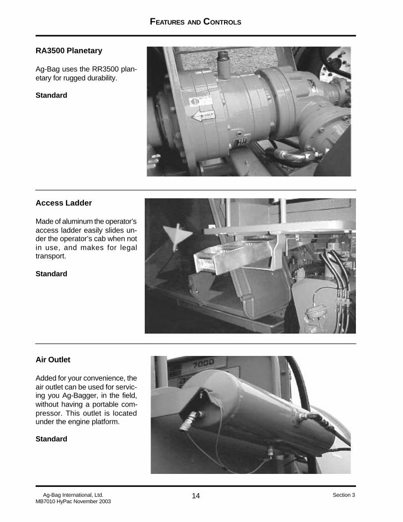
RA3500 Planetary
Ag-Bag uses the RR3500 plan-etary for rugged durability.
Standard
Access Ladder
Made of aluminum the operator’saccess ladder easily slides un-der the operator’s cab when notin use, and makes for legaltransport.
Standard
Air Outlet
Added for your convenience, theair outlet can be used for servic-ing you Ag-Bagger, in the field,without having a portable com-pressor. This outlet is locatedunder the engine platform.
Standard

FEATURES AND CONTROLS
15 Ag-Bag International, Ltd.MB7010 HyPac November 2003
Section 3
Bag Boom
Operated by hydraulics the bagboom swings forward and backand also extends. The bag boomcan be used for installing tunnelextensions as well as installingthe Ag-Bag® Bag.
Standard
Bag Boom Swing
For ease of operating the bagboom, a hydraulic ram has beenadded to swing the boom backand forth.
Standard
Bag Boom and Pan Con-trols
Located below the engine plat-form on the rear of the Ag-Bag-ger® these controls are used tolift and lower the bag pan. Rotate,extend, lift and lower the bagboom.
Standard

FEATURES AND CONTROLS
16Ag-Bag International, Ltd.MB7010 HyPac November 2003
Section 3
Pintle Hitch
The Pintle Hitch, when properlyinstalled allows for the towing ofthe Ag-Bagger®. Before towingyour Ag-Bagger® make sure youknow and understand all laws inyour area.
Standard
Feed Table Lock
The Feed Table Lock is used tolock the feed table in the up posi-tion for transport. It is stronglyrecommended that you do notmove your Ag-Bagger® from onebagging location to another without first locking the feed table.
Standard
Feed Table Wing Lock
This locking device should beused anytime the feed table israised into the up position, it willkeep you from damaging the feedtable wings.
Standard

FEATURES AND CONTROLS
17 Ag-Bag International, Ltd.MB7010 HyPac November 2003
Section 3
Hydraulic Pressure Gauges
Located to the left of theoperator’s counsel, outside thecab, these gauges are used tomonitor hydraulic pressure asfollows
1. Anchor Pressure2. System Pressure - Cab End3. System Pressure - EngineEnd
Standards
Hydraulic Wheel Drive
Your Ag-Bagger® is equippedwith four wheel drive. Eachwheel is driven by separate wheeldrive units.
Standard
Cable Feed Out Guide
Located to the left of the Hydrau-lic Pressure Gauges this indi-cated the total feet of cable thathas been fed out while bagging.The indicator is in feet.
Standard
1
2
3
FEATURES AND CONTROLS
18Ag-Bag International, Ltd.MB7010 HyPac November 2003
Section 3
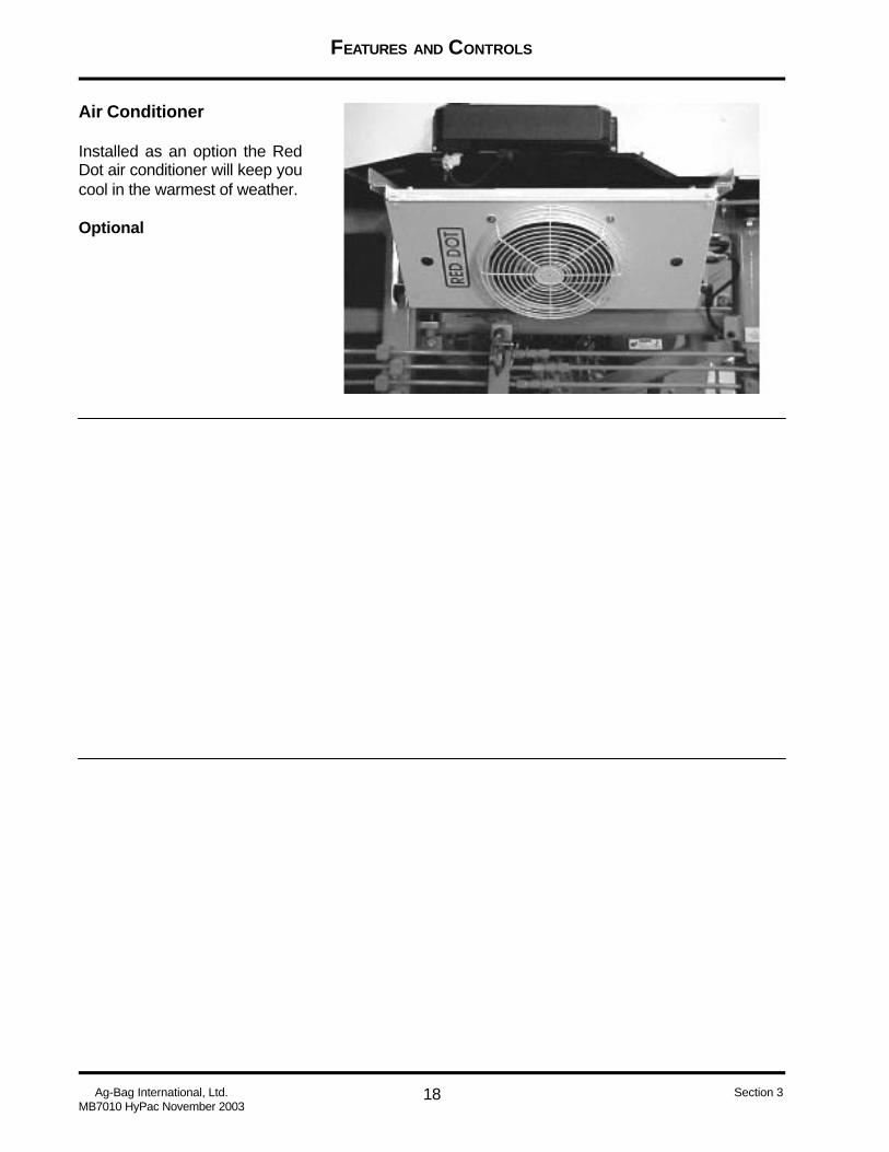
Air Conditioner
Installed as an option the RedDot air conditioner will keep youcool in the warmest of weather.
Optional

FEATURES AND CONTROLS
19 Ag-Bag International, Ltd.MB7010 HyPac November 2003
Section 3
Index
A
Access Ladder 14Air Brake Control - Cab End 5Air Brake Control - Engine End 5Air Brake Gauge - Cab End 5Air Brake Gauge - Engine End 5Air Conditioner 18Air Outlet 14Anchor Float 4Anchor In/Out 4Arm Rest Controls 4
B
Bag Boom 15Bag Boom and Pan Controls 15Bag Boom Swing 15Beater Bar Direction 4
C
Cab Heating - A/C Controls 3Cable Anchor 13Cable Feed Out Guide 17Cast Alloy Tine Cap 9Cigar Lighter 4
D
Diagnostics Gauge 4Double Beater Bars 11Dry Inoculant Applicator 6
F
Feed Table Adjuster 13Feed Table Belt 11Feed Table Lift/Lower 4Feed Table Lock 16Feed Table Speed Control 5Feed Table Wheel 12Feed Table Wing 10Feed Table Wing Lock 16Fuse Panel 5, 6
H
Horn 4Hyd Lift Jack Cab End 4Hyd Lift Jack Engine End 4Hydraulic Bag Pan 13Hydraulic Lift Jack 10Hydraulic Lift Jack Controls - External
12Hydraulic Pressure Gauges 17Hydraulic Wheel Drive 17
I
Idle Speed 4Ignition Switch 4
J
Jumbo Inoculant Applicator 7
L
Liquid Inoculant Sprayer 7
M
Mode Switch 4Motor Platform Adjustment 10
P
Pintle Hitch 16Platform Roller Cams 10
R
RA3500 Planetary 14Rotor 8Rotor Control 4
S
S Cam Air Brake 9Signal Lights 4Sound-Gard® Cab 2
Sprayer 4Steering - Cab End 5Steering - Engine End 5Sweeping Hydraulic Tunnel Clean Out
- Front View 8Sweeping Hydraulic Tunnel Clean Out
- Rear View 8
T
Tachometer 5Tunnel Clean Out 4Tunnel Clean Out Open Light 5Tunnel Extension Pins 9
W
Warning Devices 12Wheel Drive - Cab End 5Wheel Drive - Engine End 5

SETUP AND OPERATING PROCEDURES
1 Ag-Bag International, Ltd.MB7010 HyPac November 2003
Section 4
To obtain the best performance from your Ag-Bagger® it is important that you read and understand thesetup and operating procedures contained in this manual. You should also assure that all personal whowill be operating the Ag-Bagger® read and understand this material. Special attention should be paid tothe warnings contained in the manual. Remember Safety is First in operating this equipment. Your Ag-Bag® Dealer will assist you in the initial setup of you Ag-Bagger® and provide you with assistance inobtaining the best results.
AG-BAGGER® MODEL
MB7010 HyPac

SETUP AND OPERATING PROCEDURES
2Ag-Bag International, Ltd.MB7010 HyPac November 2003
Section 4
Table of Contents
PRE-OPERATION CHECK LIST ......................................................................................................... 3
OPERATOR’S PLATFORM POSITIONING ......................................................................................... 4
PINTLE HITCH...................................................................................................................................... 5
WHEEL POSITION............................................................................................................................... 6
ARM REST CONTROLS...................................................................................................................... 7
CENTER CONSOLE CONTROLS .................................................................................................... 10
SIGHT GAUGE LOCATIONS .............................................................................................................. 12
CHECK FOR HYDRAULIC LEAKS .................................................................................................... 14
STARTING THE ENGINE .................................................................................................................... 14
CHECK FOR AIR LEAKS ................................................................................................................... 15
CHECK SYSTEM PRESSURE .......................................................................................................... 15
TUNNEL EXTENSION - INSTALL ....................................................................................................... 16
FEED TABLE PREPARATION ........................................................................................................... 17
IDENTIFYING YOUR AG-BAG® BAG ................................................................................................. 18
WHAT SIZE AG-BAG® BAG CAN I USE? .......................................................................................... 18
INSTALLING THE AG-BAG® BAG ...................................................................................................... 19
BAGGING PROCEDURE ................................................................................................................... 24
TOWING THE AG-BAGGER .............................................................................................................. 30
INDEX ................................................................................................................................................. 31

SETUP AND OPERATING PROCEDURES
3 Ag-Bag International, Ltd.MB7010 HyPac November 2003
Section 4
PRE-OPERATION CHECK LIST
Prior to operating your Ag-Bagger® it is important that you preform the following checks.
_____ Review Service Manual to make sure all scheduled maintenance has been preformed.
_____ Check the following fluid levels. Levels should not exceed manufactures recommendations.Check all Operators Manuals to assure proper levels are maintained:____ Engine Fuel____ Engine Oil____ Hydraulic Oil Tank____ Engine Water Level____ Planetary Oil
Start Engine - Follow engine manufactures recommended procedures for starting the engine.
_____ Check system hydraulic pressure
_____ Check system air pressure
_____ Check system brake system
It is important that all safety procedures be followed while preforming these checks.

SETUP AND OPERATING PROCEDURES
4Ag-Bag International, Ltd.MB7010 HyPac November 2003
Section 4
OPERATOR’S PLATFORM POSITIONING
Operator’s Platform - BaggingPosition
Operator’s Platform ReleaseRod.
This rod is used when moving theOperator’s Platform from trans-port to operating positions. Bypulling the rod the platform is re-leased and will move in and outto the desired position.
Operator’s Platform - Trans-port Position
This illustration shows theOperator’s Platform in the trans-port/storage position, also notethat the access ladder is placedunder the platform in it’s storagearea.
This illustration shows theOperator’s Platform pulled outinto the bagging position. Theaccess ladder has also beenpulled out of the storage area.
SETUP AND OPERATING PROCEDURES
5 Ag-Bag International, Ltd.MB7010 HyPac November 2003
Section 4
PINTLE HITCH
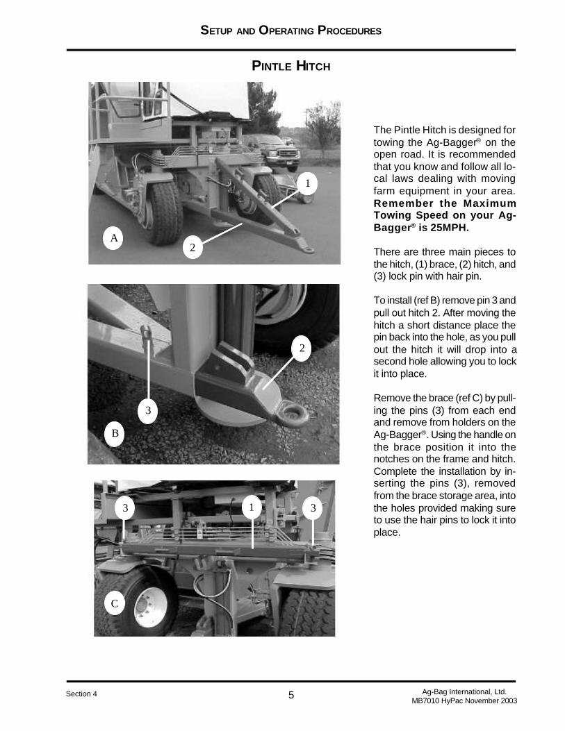
The Pintle Hitch is designed fortowing the Ag-Bagger® on theopen road. It is recommendedthat you know and follow all lo-cal laws dealing with movingfarm equipment in your area.Remember the MaximumTowing Speed on your Ag-Bagger® is 25MPH.
There are three main pieces tothe hitch, (1) brace, (2) hitch, and(3) lock pin with hair pin.
To install (ref B) remove pin 3 andpull out hitch 2. After moving thehitch a short distance place thepin back into the hole, as you pullout the hitch it will drop into asecond hole allowing you to lockit into place.
Remove the brace (ref C) by pull-ing the pins (3) from each endand remove from holders on theAg-Bagger®. Using the handle onthe brace position it into thenotches on the frame and hitch.Complete the installation by in-serting the pins (3), removedfrom the brace storage area, intothe holes provided making sureto use the hair pins to lock it intoplace.
1
2A
13 3
C
3
2
B
SETUP AND OPERATING PROCEDURES
6Ag-Bag International, Ltd.MB7010 HyPac November 2003
Section 4
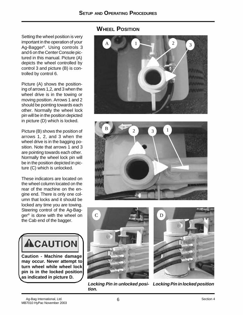
Locking Pin in unlocked posi-tion.
Locking Pin in locked position
WHEEL POSITION
Setting the wheel position is veryimportant in the operation of yourAg-Bagger®. Using controls 3and 6 on the Center Console pic-tured in this manual. Picture (A)depicts the wheel controlled bycontrol 3 and picture (B) is con-trolled by control 6.
Picture (A) shows the position-ing of arrows 1,2, and 3 when thewheel drive is in the towing ormoving position. Arrows 1 and 2should be pointing towards eachother. Normally the wheel lockpin will be in the position depictedin picture (D) which is locked.
Picture (B) shows the position ofarrows 1, 2, and 3 when thewheel drive is in the bagging po-sition. Note that arrows 1 and 3are pointing towards each other.Normally the wheel lock pin willbe in the position depicted in pic-ture (C) which is unlocked.
These indicators are located onthe wheel column located on therear of the machine on the en-gine end. There is only one col-umn that locks and it should belocked any time you are towing.Steering control of the Ag-Bag-ger® is done with the wheel onthe Cab end of the bagger.
Caution - Machine damagemay occur. Never attempt toturn wheel while wheel lockpin is in the locked positionas indicated in picture D.
A
C D
B 12 3
2 31

SETUP AND OPERATING PROCEDURES
7 Ag-Bag International, Ltd.MB7010 HyPac November 2003
Section 4
The Arm Rest console keeps thebagging operation of your Ag-Bagger® at your finger tips. Theelectric over hydraulics keep thehydraulics out of the cab.
ARM REST CONTROLS
1. Signal Lights Switch: Pressthe top of the switch to illuminatethe green light. Press the bottomof the switch to illuminate the redlight.
2. Horn Switch: Press and holdtop to sound horn.
3. Rotor Control: Press top ofswitch to start rotor and lowerbeater bar. Press bottom ofswitch to stop them.
4. Beater Bar Switch: Presstop of switch for counterclock-wise rotation. Press bottom ofswitch for clockwise rotation.Center position of switch will stoprotation. Controls upper beaterbar only.
5. Diagnostic Gauge: Allows theoperator to view many readoutsof engine functions and troublecodes. Refer to the your engineoperator’s manual for explana-tion of these codes.
6. Ignition Switch: The four po-sition key switch controls theelectrical system. Use thisswitch to start and stop engine.
7. Idle Control Switch: Turnknob clockwise to increase idleand counter clockwise to de-crease. Use bottom knob to lockidle at desired speed.
43
21
5 6
7
8
9
10
11
12
13
14
15
16
SETUP AND OPERATING PROCEDURES
8Ag-Bag International, Ltd.MB7010 HyPac November 2003
Section 4
ARM REST CONTROLS (CONT.)
43
21
5 6
7
8
9
10
11
12
13
14
15
16
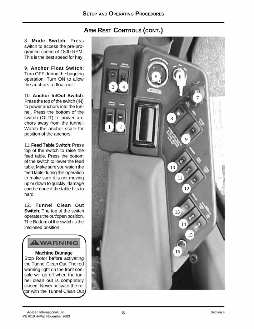
8. Mode Switch: Pressswitch to access the pre-pro-gramed speed of 1800 RPM.This is the best speed for hay.
9. Anchor Float Switch:Turn OFF during the baggingoperation. Turn ON to allowthe anchors to float out.
10. Anchor In/Out Switch:Press the top of the switch (IN)to power anchors into the tun-nel. Press the bottom of theswitch (OUT) to power an-chors away from the tunnel.Watch the anchor scale forposition of the anchors.
11. Feed Table Switch: Presstop of the switch to raise thefeed table. Press the bottomof the switch to lower the feedtable. Make sure you watch thefeed table during this operationto make sure it is not movingup or down to quickly, damagecan be done if the table hits tohard.
12. Tunnel Clean OutSwitch: The top of the switchoperates the out/open position.The Bottom of the switch is thein/closed position.
Machine DamageStop Rotor before activatingthe Tunnel Clean Out. The redwarning light on the front con-sole will go off when the tun-nel clean out is completelyclosed. Never activate the ro-tor with the Tunnel Clean Out

SETUP AND OPERATING PROCEDURES
9 Ag-Bag International, Ltd.MB7010 HyPac November 2003
Section 4
ARM REST CONTROLS (CONT.)13. Sprayer Switch: Press thetop of the switch to turn ON theinoculant applicator. Press thebottom of the switch to turn OFFthe inoculant applicator.
14. Lift Jack Switch - EngineEnd: Press and hold the top ofthe switch to LIFT the engine endof the Ag-Bagger® off the ground.Press and hold the bottom of theswitch to LOWER the engineend to the ground.
15. Lift Jack Switch - Cab End:Press and hold top of the switchto LIFT the cab end of the Ag-Bagger® off the ground. Pressand hold the bottom of the switchto LOWER the engine end to theground.
16. Accessory Plug-In: A 12vpower outlet is provided for usewith cell phones, computers orany other device requiring thistype of power.
NEED NEW PICTURE
43
21
5 6
7
8
9
10
11
12
13
14
15
16

SETUP AND OPERATING PROCEDURES
10Ag-Bag International, Ltd.MB7010 HyPac November 2003
Section 4
CENTER CONSOLE CONTROLS
1. Air Brake Control - EngineEnd: Regulates the brake pres-sure on the cab end of the Ag-Bagger®.
2. Feed Table Speed Control:Forward moves the belt/feed to-wards the rotor. Back moves thebelt/feed away from the rotor.
3. Steering - Engine End: Movethe handle to turn the wheel po-sition. Use the mirror to observe
white arrows for wheel position.
4. Wheel Drive - Engine End:Controls the speed and rotationof the wheels on the engine endof the Ag-Bagger®.
5. Wheel Drive - Cab End: Con-trols the speed and rotation of thewheel on the cab end of the Ag-Bagger®,
6. Steering - Cab End: Move thehandle to turn the wheel position.Observe the wheel position out
side of cab.
7. Air Brake Control - Cab End:Regulates the brake pressure onthe cab end of the Ag-Bagger®.
8. Air Brake Gauge - Cab End:The white indicator needle is thecab end operating pressure.
1 2 3 4 5 6 7
89
10
11
12

SETUP AND OPERATING PROCEDURES
11 Ag-Bag International, Ltd.MB7010 HyPac November 2003
Section 4
CENTER CONSOLE CONTROLS (CONT.)
11. Brake Pressure Gauge -Engine End: the red indicatorneedle is the system pressure.The white needle is the engineend operating pressure.
12. Fuse Panel (not shown)
1 2 3 4 5 6 7
89
10
11
12
9. Tachometer: Indicates engineRPM.
10. Tunnel Clean Out OpenLight: When lit this light indicatesthat the tunnel clean out sweepis open.
Do not operated Rotor whenthis light is lit.
SETUP AND OPERATING PROCEDURES
12Ag-Bag International, Ltd.MB7010 HyPac November 2003
Section 4
SIGHT GAUGE LOCATIONS
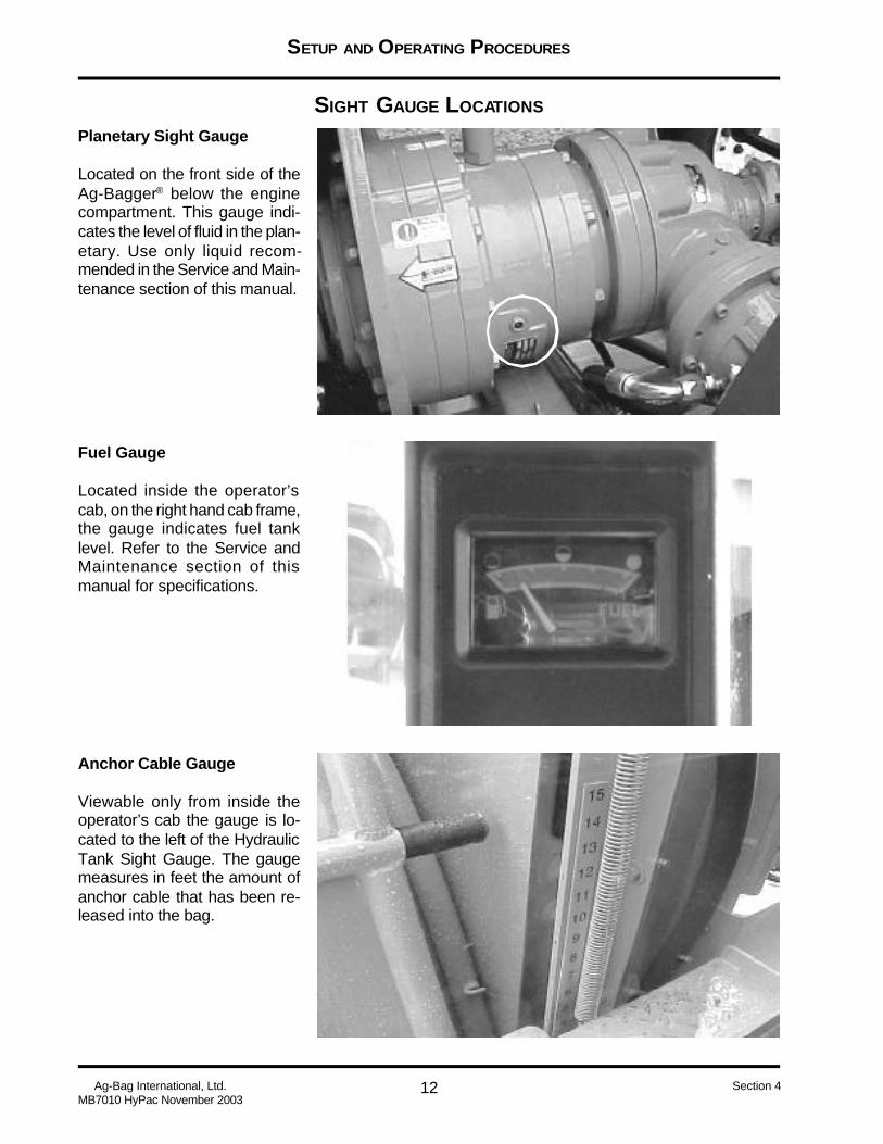
Anchor Cable Gauge
Viewable only from inside theoperator’s cab the gauge is lo-cated to the left of the HydraulicTank Sight Gauge. The gaugemeasures in feet the amount ofanchor cable that has been re-leased into the bag.
Planetary Sight Gauge
Located on the front side of theAg-Bagger® below the enginecompartment. This gauge indi-cates the level of fluid in the plan-etary. Use only liquid recom-mended in the Service and Main-tenance section of this manual.
Fuel Gauge
Located inside the operator’scab, on the right hand cab frame,the gauge indicates fuel tanklevel. Refer to the Service andMaintenance section of thismanual for specifications.

SETUP AND OPERATING PROCEDURES
13 Ag-Bag International, Ltd.MB7010 HyPac November 2003
Section 4
SIGHT GAUGE LOCATIONS (CONT.)Hydraulic Tank Sight Gauge
Viewable only from inside theoperator’s cab the gauge is lo-cated between the fuel and hy-draulic tanks. The gauge indi-cates hydraulic tank level as wellas temperature. See the Serviceand Maintenance section of thismanual for specifications.

SETUP AND OPERATING PROCEDURES
14Ag-Bag International, Ltd.MB7010 HyPac November 2003
Section 4
CHECK FOR HYDRAULIC LEAKS
Checking for Hydraulic Leaks
Before starting engine and charging the hydraulic system do a slow walk around the Ag-Bagger®.Inspect all hydraulic connections for any indications of fluid seepage. Using a clean dry rag wipe areawhere there might be an indication of leakage. Remember to never place your hand over any hydraulichose, fitting or pipe while the engine is running and the hydraulic system is charged. Refer to theService and Maintenance section of this manual for the correct fluid to use in the hydraulic system.
STARTING THE ENGINE
Serious injury or death my occur.
Make sure everyone is well clear ofany moving parts on the Ag-Bagger®
before starting engine.
Starting the engine.
Before starting the engine makesure everyone is away from anymoving parts of the Ag-Bagger®.Review the correct starting pro-cedures as outlined in theOwner’s manual of the engine onthis machine. The manual wassupplied with the Ag-Bagger®
when purchased.
CHECK FOR AIR LEAKS
Serious injury may occur. Do notuse hands to check for air leaks.High pressure air injections maycause serious injury.
Check for air leaks.
After starting engine do a slowwalk around of the Ag-Bagger®,using your ears, listen for an airleak hissing sound. If you thinkthere is a leak use a solution ofwater and soap from a squeezebottle to check. If you seebubbles a leak exists. Shut downthe engine and tighten the fitting,after tightening is complete startengine and check fitting again.Remember do not use you handof finger to check for air leaks.

SETUP AND OPERATING PROCEDURES
15 Ag-Bag International, Ltd.MB7010 HyPac November 2003
Section 4
CHECK SYSTEM PRESSURE
Before you can check the system pressures you need to let the engine run for several minutes.
Check the system Air Pres-sure.
The gauge used for checking theSystem Air Pressure is locatedon the Center Control Consoleand is item #11. There are twoneedles on this gauge, (1) a redneedle which indicates the sys-tem pressure and should readbetween 100 - 120 psi as thecorrect operating pressure, and(2) a white needle which is theengine end air brake pressureindicator.
Check System Hydraulic Pres-sure.
Because the Ag-Bagger® has asplit hydraulic system, twogauges are required in order tocheck the system. The systemsare grouped as (1) Cab EndPressure and (2) Engine EndPressure. The recommend pres-sure should be 3000 psi on bothgauges.
Anchor Pressure Gauge
(3) Indicates the pressure placedon the anchor cables during thebagging operation
SYSTEM AIR PRESSURE
1 2
SYSTEM HYDRAULIC PRESSURE
1
2
3
SETUP AND OPERATING PROCEDURES
16Ag-Bag International, Ltd.MB7010 HyPac November 2003
Section 4
1 22
4
5
3
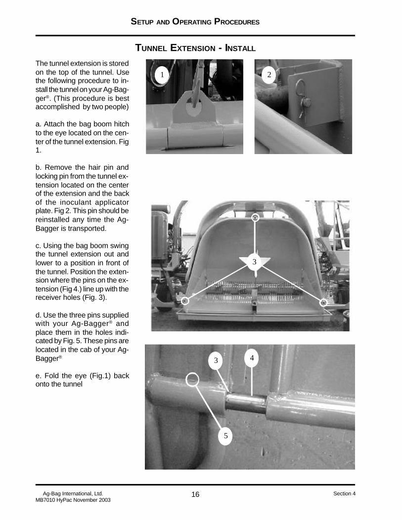
The tunnel extension is storedon the top of the tunnel. Usethe following procedure to in-stall the tunnel on your Ag-Bag-ger®. (This procedure is bestaccomplished by two people)
a. Attach the bag boom hitchto the eye located on the cen-ter of the tunnel extension. Fig1.
b. Remove the hair pin andlocking pin from the tunnel ex-tension located on the centerof the extension and the backof the inoculant applicatorplate. Fig 2. This pin should bereinstalled any time the Ag-Bagger is transported.
c. Using the bag boom swingthe tunnel extension out andlower to a position in front ofthe tunnel. Position the exten-sion where the pins on the ex-tension (Fig 4.) line up with thereceiver holes (Fig. 3).
d. Use the three pins suppliedwith your Ag-Bagger® andplace them in the holes indi-cated by Fig. 5. These pins arelocated in the cab of your Ag-Bagger®
e. Fold the eye (Fig.1) backonto the tunnel
TUNNEL EXTENSION - INSTALL
3
SETUP AND OPERATING PROCEDURES
17 Ag-Bag International, Ltd.MB7010 HyPac November 2003
Section 4
FEED TABLE PREPARATION
1
3
4
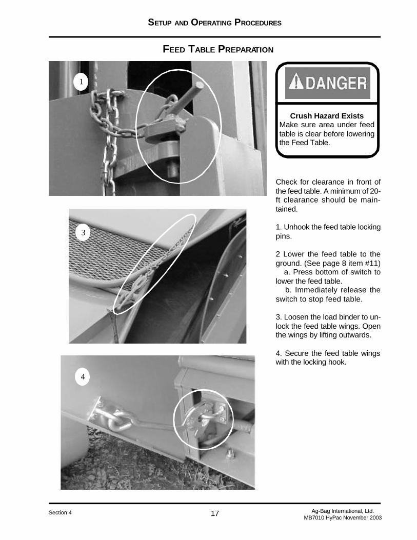
Check for clearance in front ofthe feed table. A minimum of 20-ft clearance should be main-tained.
1. Unhook the feed table lockingpins.
2 Lower the feed table to theground. (See page 8 item #11) a. Press bottom of switch tolower the feed table. b. Immediately release theswitch to stop feed table.
3. Loosen the load binder to un-lock the feed table wings. Openthe wings by lifting outwards.
4. Secure the feed table wingswith the locking hook.
Crush Hazard ExistsMake sure area under feedtable is clear before loweringthe Feed Table.
SETUP AND OPERATING PROCEDURES
18Ag-Bag International, Ltd.MB7010 HyPac November 2003
Section 4
IDENTIFYING YOUR AG-BAG® BAG
WHAT SIZE AG-BAG® BAG CAN I USE?
MB7010 HyPac
10 Foot TunnelTD1015TD1020TD1025TD1030
1 2
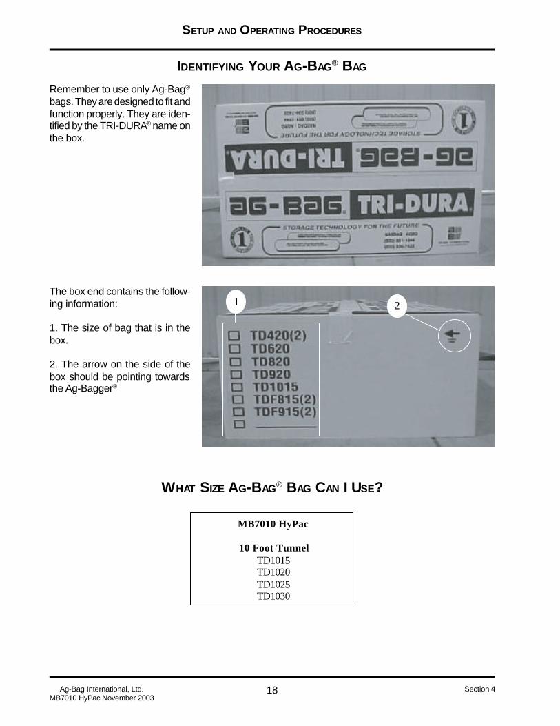
Remember to use only Ag-Bag®
bags. They are designed to fit andfunction properly. They are iden-tified by the TRI-DURA® name onthe box.
The box end contains the follow-ing information:
1. The size of bag that is in thebox.
2. The arrow on the side of thebox should be pointing towardsthe Ag-Bagger®

SETUP AND OPERATING PROCEDURES
19 Ag-Bag International, Ltd.MB7010 HyPac November 2003
Section 4
INSTALLING THE AG-BAG® BAG
1. Move the Ag-Bagger® to theposition where you want the bagto begin. Make sure you haveabout 10’ of clear area behind thetunnel.
2. Using the steering controlson the center console movethe wheels into bagging posi-tion, make sure that arrows(1a) and (1b) align.
3. After moving the wheel makesure the locking pin located be-hind arrow (1b) is not in thelocked position as shown in fig.2.
4. Using the controls on the armrest console, lower feed table,unlock and lift feed table wingslocking them into position.
Machine damage may occur.Never attempt to turn wheelwhile wheel lock pin is in thelocked position as indicated inpicture 3.
Locking Pin in unlocked posi-tion.
Locking Pin in locked position
2 3
4
a b1
Crush Hazard ExistsMake sure area under feedtable is clear before loweringthe Feed Table.

SETUP AND OPERATING PROCEDURES
20Ag-Bag International, Ltd.MB7010 HyPac November 2003
Section 4
The next steps are preformedusing the hydraulic control leversshown in fig.8. (8a) is for open-ing and closing the bag pan. (8b)moves the bag boom extensionin and out. (8c) lowers and raisesthe bag boom cable. (8d) rotatesthe bag boom in and out. It isimportant that you have enoughslack in cable to extend boom.
8. Feed out enough cable us-ing control (8c) so the hook onthe cable can be attached to thebag cradle. Raise the cradleand rotate it using (8d) and (8b)until you can set the cradle onthe ground near the tunnelopening, it should be close tothe center of the tunnel. Do notdisconnect cable. Using (8a)fully open the bag pan.
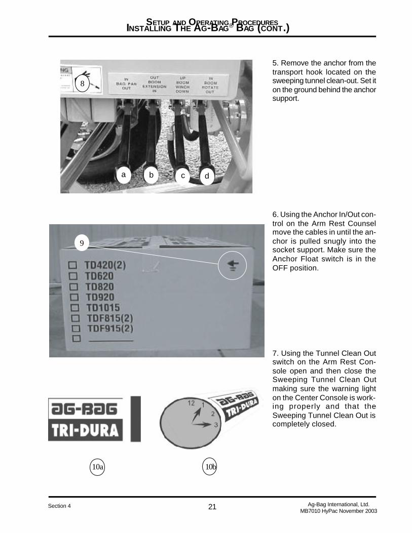
9. Line the bag box up with thebag cradle, making sure the ar-row on the box end is pointingtowards the tunnel. Cut the plas-tic bands and remove the outerlid. Remove the inner shell andplastic inserts and the box will layflat. Do not remove tape or ropeuntil bag is on the tunnel.
10. Unfold the bag and lift the tophalf of the bag and place it on thebag cradle. Using the bag boomraise the bag and then rotate thebag on the cradle until (10a) islocated in between the 1 and 3o’clock (10b)
INSTALLING THE AG-BAG® BAG (CONT.)
7
5
6
SETUP AND OPERATING PROCEDURES
21 Ag-Bag International, Ltd.MB7010 HyPac November 2003
Section 4
INSTALLING THE AG-BAG® BAG (CONT.)
10b10a
9
8
a b c d
5. Remove the anchor from thetransport hook located on thesweeping tunnel clean-out. Set iton the ground behind the anchorsupport.
6. Using the Anchor In/Out con-trol on the Arm Rest Counselmove the cables in until the an-chor is pulled snugly into thesocket support. Make sure theAnchor Float switch is in theOFF position.
7. Using the Tunnel Clean Outswitch on the Arm Rest Con-sole open and then close theSweeping Tunnel Clean Outmaking sure the warning lighton the Center Console is work-ing properly and that theSweeping Tunnel Clean Out iscompletely closed.

SETUP AND OPERATING PROCEDURES
22Ag-Bag International, Ltd.MB7010 HyPac November 2003
Section 4
INSTALLING THE AG-BAG® BAG (CONT.)
11
12
Possibility of bag dam-age. A minimum 3/4 inchgap must remain be-tween the tunnel andbag pan.
11. Continue to raise the bag androtate it toward the tunnel pullingthe sides of the bag out to fitaround the tunnel extension. Pickup the lower part of the bag andplace it into the bag pan makingsure it is laying flat in the bag pan.When this is done move the bagback and set the cradle downonto the tunnel. Do not rest thebag on the extension.
Remove all the tape or ropes thathold the bag folds together.
12. Recheck and make sure alltape and ropes have been re-moved from the bag. Using thecontrol 8a close the bag pan un-til there is approximately 3/4clearance between the bag panand tunnel.
Using the bungee cord suppliedwith the Ag-Bagger® stretch itacross the top of the tunnel andplace the hooks into the holesdrilled in the bag pan.
Locate the three hooks locatedat the back of the tunnel and tiestrings to the bungee cord andattach it to these hooks. Thiskeeps the bungee from moving.
Note: The Ag-Bagger® used forthese photos is not the MB7010but the procedures are the same.

SETUP AND OPERATING PROCEDURES
23 Ag-Bag International, Ltd.MB7010 HyPac November 2003
Section 4
INSTALLING THE AG-BAG® BAG (CONT.)
3d 3e
2
Seal the Beginning End of theBag
1. Pull off enough bag to applythe seal. Pull from the insidefolds, not the outside folds(white on the outside, black onthe inside). Make sure you pullthe bag under the bag bungeecord.
2. Seal the end of the bag us-ing Master Seal®. Follow the in-structions included with theMaster Seal® . Master Seal® ,tool, and sealing board areavailable from your Ag-Bag®
Dealer.
3. OR, use a Double Knot Tie.(a) find the end of the bag; (b)gather the bag to the center; (c)twist the bag tight; (d) tie the bagtight. Leave enough bag to foldover and (e) tie a second timegiving the bag an airtight seal.
4. Slide excess bag back onto thetunnel and bag pan. Position theknot knee high.
This illustration shows a bag in-stalled and ready for use. Thedouble knot was used to seal theend of the bag.
SETUP AND OPERATING PROCEDURES
24Ag-Bag International, Ltd.MB7010 HyPac November 2003
Section 4
BAGGING PROCEDURE
THINK SAFETY AT ALL T IMES
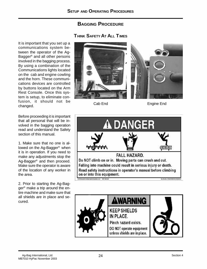
It is important that you set up acommunications system be-tween the operator of the Ag-Bagger® and all other personsinvolved in the bagging process.By using a combination of theCommunications lights locatedon the cab and engine cowlingand the horn. These communi-cations devices are controlledby buttons located on the ArmRest Console. Once this sys-tem is setup, to eliminate con-fusion, it should not bechanged.
Before proceeding it is importantthat all personal that will be in-volved in the bagging operationread and understand the Safetysection of this manual.
1. Make sure that no one is al-lowed on the Ag-Bagger® whenit is in operation. If you need tomake any adjustments stop theAg-Bagger® and then proceed.Make sure the operator is awareof the location of any worker inthe area.
2. Prior to starting the Ag-Bag-ger® make a trip around the en-tire machine and make sure thatall shields are in place and se-cured.
Engine EndCab End

SETUP AND OPERATING PROCEDURES
25 Ag-Bag International, Ltd.MB7010 HyPac November 2003
Section 4
BAGGING PROCEDURE (CONT.)
START-UP PROCEDURE
1. Using the warning procedure setup as part of your communications discussed on the prior pagewarn all people to move away from the Ag-Bagger® After giving them enough time to clear the area, usethe safety mirrors and visually make sure the area is clear.
2. Start the Engine. Using switch #6 shown on page 7, follow the procedures outlined in the Operator’sManual for the engine installed on your Ag-Bagger®. Check all warning lights, and diagnostics prior toproceeding.
3. Start the rotor. Using the Rotor Switch on the Arm Rest Console.
4. Start the Feed Table. Refer to page 10 of this manual, using control #2 to start the feed table.
5. Start Upper Beater Bar. Refer to page 7 of this manual, using control #4 start the beater bar. Thiscontrols only the upper beater bar.
FILLING THE AG-BAG® BAG
1. Using the brake control and gauges (page 10, controls items #1 and #7 and gauges items #8 and#15) set the brake pressure on all wheels to approximately 40psi.
2. Check Anchor Float switch (page 8 item #9) to make sure it is in the OFF position.
3. Using the established communications procedure start the product moving into the bag.
4. If the Ag-Bagger® has an Inoculant applicator start it now.
5. Monitor the loads placed into the bags. When you have bagged between 20 - 30 tons of product turnthe Anchor Float switch ON (page 8 item #9) and lower wheel brake pressure to 20 psi. Watch theAnchor Float Gauge (page 14) when the gauge reaches 6 - 10 feet (this setting depends on the condi-tion of crop, the wetter the crop the less amount of cable should be out) turn the Anchor Float switchOFF. Reduce wheel brake pressure to 10 psi after turning switch off.
6. Anchor pressure readings. After turning the Anchor Float off maintain the Anchor pressure at 500-1000 psi for Corn and 1200-1600 for all other crops. Use the gauge on page 4.16 item #3 to monitor thispressure. The amount of pressure is controlled by feeding out more cable to increase the amount ofdrag/pressure and pulling in cable to lower the drag/pressure. These pressure readings will vary de-pending on the moisture in the product being bagged. It is very important that you continually monitorthe pressure to make sure they remain in the range specified.
BEFORE STARTING TO BAG IT IS IMPORTANT THAT YOU READ AND UNDERSTAND
OTHER SECTIONS OF THIS MANUAL. BAGGING AND THE TERRAIN, 3M’S OF
SILAGE AND BAGGING INSTRUCTIONS.

SETUP AND OPERATING PROCEDURES
26Ag-Bag International, Ltd.MB7010 HyPac November 2003
Section 4
REMOVING THE AG-BAG® BAG
BAGGING PROCEDURE (CONT.)
It is important that you monitor the length of the bag and the number of folds remaining on the tunnel.Start the following procedure when there is 6 - 7 folds of bag remaining on the tunnel.
1. Prior to the last load pull anchor in. Increase the brake pressure, and using switch #10 on page 8 pullthe anchors in. When the final load is in the bag there should be approximately 5 folds left on the tunnel.
2. Release the brake pressure.
3. Using Sweeping Tunnel Sweep switch (see item #12 page 8) to open and close the sweep. Repeatthis procedure several times. Make sure when you have finished the Sweep warning light on the centerconsole is out (See item #10 page 10).
4. If you are going to start a new bag at the end of this bag pull the Ag-Bagger® forward until the bag hasbeen pulled from the tunnel. If you are going to move to a new location and will be turning the Ag-Baggerlift the feed table, remembering to close the feed table wings prior to lifting the feed table.
5. When the bagger has been moved away pull the plastic flat and prepare to seal the end of the bag.Grab each side of the bag on the end. Walk the bag over itself pulling the product together. Bring thebag end back forward. Seal the end of the bag with either MasterSeal® or double knot tie.
“No matter what method is used when sealing the end of the bag, loose plastic should beweighted down.” See the Bagging and the Terrain Section. (Section 5)
6. Install Vent Valves. Place the vent valve 10-ft from the end of the bag and approximately 3/4 up theheight of the bag.
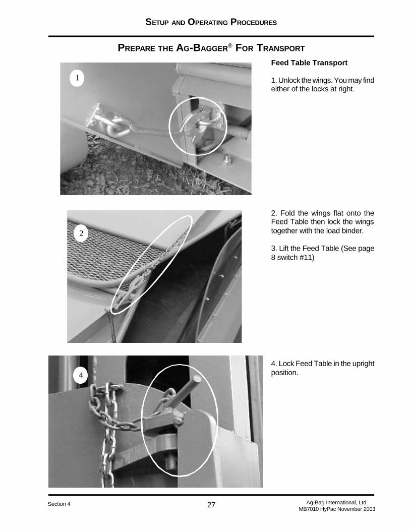
SETUP AND OPERATING PROCEDURES
27 Ag-Bag International, Ltd.MB7010 HyPac November 2003
Section 4
PREPARE THE AG-BAGGER® FOR TRANSPORT
Feed Table Transport
1. Unlock the wings. You may findeither of the locks at right.
2. Fold the wings flat onto theFeed Table then lock the wingstogether with the load binder.
3. Lift the Feed Table (See page8 switch #11)
4. Lock Feed Table in the uprightposition.
2
1
4

SETUP AND OPERATING PROCEDURES
28Ag-Bag International, Ltd.MB7010 HyPac November 2003
Section 4
21 4
PREPARE THE AG-BAGGER® FOR TRANSPORT
Wheel Transport
1. Using the steering controls onthe center console move thewheels into transport position.
2. Align the arrows on the wheelcolumn. Maker sure arrows (a)and (b) align.
3. Lock the wheels.
Tunnel Extension Transport
1. Latch bag boom hook to liftinglug at top of tunnel extension.
2. Remove pins from all sockets,and pull extension away from tun-nel.
3. Using the bag boom lift the tun-nel extension and set it on top ofthe tunnel.
4. Insert pin into transport re-ceiver.
a
b
2

SETUP AND OPERATING PROCEDURES
29 Ag-Bag International, Ltd.MB7010 HyPac November 2003
Section 4
PREPARE THE AG-BAGGER® FOR TRANSPORT
Anchor Transport
1. After removing anchor fromthe bag during bagging opera-tion move anchor to hook lo-cated in the tunnel and hang itthere.
2. Fold anchor support socketback into tunnel.
3. Using the controls on the ArmRest Console take the slack outof the cable.
Pintle Hitch Transport
Use only the pintle hitch providefor towing the Ag-Bagger®
1. Remove the pin and hair pinand slide the hitch out.
2. Remove the hitch stabilizerfrom its storage position.
3. Place hitch stabilizer into thereceiver on the hitch and insertpins to lock into position.
Caution should be usedto leave some slack inthe cables. Pulling totight will cause cable tokink.
2
3
1
2

SETUP AND OPERATING PROCEDURES
30Ag-Bag International, Ltd.MB7010 HyPac November 2003
Section 4
TOWING THE AG-BAGGER
1. Using the lift jack raise the Ag-Bagger®
2. Lineup the towing vehicle with the pintle hitch. Make sure you use a vehicle rated to tow your Ag-Bagger.
3. Using the lift jack lower the Ag-Bagger® onto the pintle hitch.
4. Shut off Ag-Bagger® engine.
5. Connect the Ag-Bagger® lights to the tow vehicle. The connector should have been installed to thefour wire harness.
6. Attach air brake hose to the Ag-Bagger® The connector is located above the pintle hitch stabilizer.
7. It is your responsibility to know follow all state and local laws dealing with the movement of agricul-tural equipment on highways.

SETUP AND OPERATING PROCEDURES
31 Ag-Bag International, Ltd.MB7010 HyPac November 2003
Section 4
Index
A
Accessory Plug-In 9Air Brake Control - Cab End 10Air Brake Control - Engine End 10Air Brake Gauge - Cab End 10Anchor Cable Gauge 12Anchor Float Switch 8Anchor In/Out Switch 8Anchor Pressure Gauge 14Anchor Transport 28Arm Rest Controls 7
B
Bagging Procedure 24Beater Bar Switch 7Brake Pressure Gauge - Engine
End 11
C
Check for air leaks. 15Check System Hydraulic Pressure.
14Check the system Air Pressure.
14Checking for Hydraulic Leaks 14
D
Diagnostic Gauge 7
F
Feed Table Preparation 17Feed Table Speed Control 10Feed Table Switch 8Feed Table Transport 27Filling The Ag-Bag® Bag 25Fuel Gauge 12Fuse Panel 11
H
Horn Switch 7Hydraulic Tank Sight Gauge 13
I
Identifying Your Ag-Bag® 18Identifying Your Ag-Bag® Bag 18Idle Control Switch 7Ignition Switch 7Installing The Ag-Bag® Bag 19
L
Lift Jack Switch - Cab End 9Lift Jack Switch - Engine End 9
M
Machine Damage 8Mode Switch 8
O
Operator’s Platform - BaggingPosition 4
Operator’s Platform - TransportPosition 4
Operator’s Platform Positioning 4Operator’s Platform Release Rod.
4
P
Pintle Hitch 5Pintle Hitch Transport 28Planetary Sight Gauge 12Pre-Operation Check List 3
R
Removing The Ag-Bag® Bag 26Rotor Control 7
S
Signal Lights Switch 7Size Ag-Bag® Bag Can I Use? 18Sprayer Switch 9Start-up Procedure 25Starting the engine. 14Steering - Cab End 10Steering - Engine End 10
T
Tachometer 11Towing The Ag-Bagger 30Tunnel Clean Out Open Light 11Tunnel Clean Out Switch 8Tunnel Extension - Install 16Tunnel Extension Transport 28
W
What Size Ag-Bag® Bag Can IUse? 18
Wheel Drive - Cab End 10Wheel Drive - Engine End 10Wheel Position 6Wheel Transport 28

BAGGING AND THE TERRAIN
Ag-Bag International, Ltd.MB7010 HyPac November 2003
1Section 5
BAGGING AND THE TERRAIN
This section deals with placing the bag and preparing the site for best results. Also covered iskeeping the correct tension on the cables for best compactions. The information containedhere will help you to protect you investment in the feed you bag. It is important you familiarizeyourself with the information contained here as well as the information presented in the at-tached Appendixes.
AG-BAGGER® MODEL
MB7010 HyPac
2
BAGGING AND THE TERRAIN
Ag-Bag International, Ltd.MB7010 HyPac November 2003
Section 5
Table of Contents
BAG GUARANTEE............................................................................................................................... 3
BAGGING SURFACE........................................................................................................................... 4
BAD WEATHER BAGS ........................................................................................................................ 4
PROTECT AGAINST THE WIND ........................................................................................................ 4
FILLING THE BAG ............................................................................................................................... 5
CONTROLLING BAG STRETCH ........................................................................................................ 5
PRODUCT MOISTURE........................................................................................................................ 6
INDEX................................................................................................................................................... 7

BAGGING AND THE TERRAIN
Ag-Bag International, Ltd.MB7010 HyPac November 2003
3Section 5
BAG GUARANTEE
We, at Ag-Bag®, can offer this unequaled guarantee because of our commitment to quality, yearsof experience as the leading manufacture of silage bags, and use of the latest plastic technology.We recognize that the quality and reliability of the bagging system is dependent on a team effortbetween Ag-Bag® and you, the customer. Our part of the teamwork is to provide you with a topquality silage bag.
AG-BAG®’S PARTAg-Bag® guarantees our “Tri-Dura®” silage bags to be free of defects in workmanship and materials.If a properly packed bag should fail from a defect during normal useful life, Ag-Bag® will replacethe bag without charge. If the feed in the damaged bag requires rebagging Ag-Bag® will replacethe bag discussed above plus one move bag, for a total of two bags.
THE CUSTOMER PARTMost of the factors that control the quality and reliability of the bagging system are in the customer’shands. These include choice of forage crops, harvesting, bagging location, moisture, packing,bagging machine operations, and maintenance and surveillance of bags.
Ag-Bag® will provide instruction, recommendations and suggestions about these factors but cannotand does not guarantee the outcome. It is the responsibility of the customer to seek out the bestinformation and to make his own decisions. The customer will be responsible for the profits orloss that results from the use of these products. See Ag-Bag® 3M’s of Silage for recommendationof how to bag silage for proper techniques and guidelines.

4
BAGGING AND THE TERRAIN
Ag-Bag International, Ltd.MB7010 HyPac November 2003
Section 5
Leaving loose plasticblowing in the windmay cause productloss. Secure bothends of the bag aftersealing. Protect yourinvestment.
Remember, place bagsin a locations that feedout can be done whenyou need the feed.
BAGGING SURFACE
Bag uphill rather than downhill. Avoid bagging on a side hill. TheAg-Bagger® can drift and bags may roll.
Surface conditions may affect bagging quality and ability. Soft groundconditions will act as a brake and may cause the Ag-Bagger® tosink. A hard clean and level surface is best to bag on. By clearingthe area rodent problems can be eliminated.
BAD WEATHER BAGS
Consider the surface conditions during the seasons when productwill be removed from the bags. If you expect a lot of mud, you maywant to put some bags on a solid surface. Have enough accessiblebags to last until good weather conditions can be expected.
PROTECT AGAINST THE WIND
Winds blowing against the plastic can cause plastic fatigue. Thismay create holes and allow oxygen into the bags. To prevent winddamage secure the loose ends of the bag.
o Pile old tires on the finished end of the bag after sealing.
o Do no use abrasive materials or forage products, rodentslike this type of cover
Do not bag on a side hill.Tip-over or bag roll mayresult.
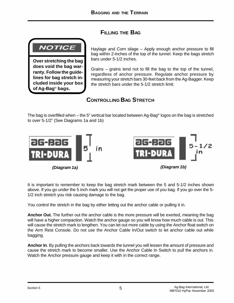
BAGGING AND THE TERRAIN
Ag-Bag International, Ltd.MB7010 HyPac November 2003
5Section 5
Over stretching the bagdoes void the bag war-ranty. Follow the guide-lines for bag stretch in-cluded inside your boxof Ag-Bag® bags.
Haylage and Corn silage – Apply enough anchor pressure to fillbag within 2-inches of the top of the tunnel. Keep the bags stretchbars under 5-1/2 inches.
Grains – grains tend not to fill the bag to the top of the tunnel,regardless of anchor pressure. Regulate anchor pressure bymeasuring your stretch bars 30-feet back from the Ag-Bagger. Keepthe stretch bars under the 5-1/2 stretch limit.
FILLING THE BAG
The bag is overfilled when – the 5” vertical bar located between Ag-Bag® logos on the bag is stretchedto over 5-1/2” (See Diagrams 1a and 1b)
(Diagram 1a) (Diagram 1b)
CONTROLLING BAG STRETCH
It is important to remember to keep the bag stretch mark between the 5 and 5-1/2 inches shownabove. If you go under the 5 inch mark you will not get the proper use of you bag. If you go over the 5-1/2 inch stretch you risk causing damage to the bag.
You control the stretch in the bag by either letting out the anchor cable or pulling it in.
Anchor Out. The further out the anchor cable is the more pressure will be exerted, meaning the bagwill have a higher compaction. Watch the anchor gauge so you will know how much cable is out. Thiswill cause the stretch mark to lengthen. You can let out more cable by using the Anchor float switch onthe Arm Rest Console. Do not use the Anchor Cable In/Out switch to let anchor cable out whilebagging.
Anchor In. By pulling the anchors back towards the tunnel you will lessen the amount of pressure andcause the stretch mark to become smaller. Use the Anchor Cable In Switch to pull the anchors in.Watch the Anchor pressure gauge and keep it with in the correct range.
6
BAGGING AND THE TERRAIN
Ag-Bag International, Ltd.MB7010 HyPac November 2003
Section 5
Over stretching the bagdoes void the bag war-ranty. Follow the guide-lines for bag stretch in-cluded inside your boxof Ag-Bag® bags.
PRODUCT MOISTURE
Refer to the “3M’s of Silage” for information on product moisturelevel. Moisture levels play an important part of product quality.
Dry Product
Dry product makes a lumpy bag. Long dry chop is hard on the Ag-Bagger®. Remember when trying to make good haylage, dry feedshave more resistance, they will pack higher in the bag, and lessbrake pressure is required.
Wet Product
Moisture levels above 70% may create excessive liquid in the hop-per. This excessive liquid is “OK” unless the bag is outside the rec-ommended shape. Slowly release brake pressure until the bag iswithin the recommended shape. Let the product wilt longer if liquiddoes not dissipate. Wet product does not rise very high in the bag.The result is a wide bag.
BAGGING AND THE TERRAIN
Ag-Bag International, Ltd.MB7010 HyPac November 2003
7Section 5
Index
A
Anchor In 5Anchor Out 5
B
Bad Weather Bags 4. See also WeatherBag Guarantee 3Bag Shape. See BaggingBagging
Bagging Surface 4Filling the Bag 5
Bagging Surface 4. See also Bagging
C
Controlling Bag Stretch 5Correcting Bag Stretch. See Bagging
D
Dry Product 6. See also Moisture
F
Filling the Bag 5. See also Bagging
M
MoistureDry Product 6Product Moisture 6Wet Product 6
P
Product Moisture 6. See also MoistureProtect Against the Wind 4. See also Weather
W
WeatherBad Weather Bags 4Protect Against the Wind 4
Wet Product 6. See also Moisture
TROUBLESHOOTING
1 Ag-Bag International, Ltd.MB7010 HyPac November 2003
Section 6
This section is not intended to address all the problems that might arise during bagging. It isintended to review some of the common problems that might arise during the bagging op-eration. If problems arise that are not covered here please contact you Ag-Bag® Dealer forhelp.
It is important to remember to follow all safety procedures while preforming any prob-lem corrections outlined in Troubleshooting section.

TROUBLESHOOTING
2Ag-Bag International, Ltd.MB7010 HyPac November 2003
Section 6
PROBLEM CAUSE CORRECTION
ROTOR DRIVE BELT SLIPPING 1. To much belt deflection.
2. Rotor plugged.
3. Product binding lower beaterbar.
1. Adjust Belt Tension. See theService and Maintenance Sec-tion.
2. Slow down Feed Table belt.
3. Adjust chop or monitor mois-ture.
FEED TABLE BELT WON’T PULL FEED
TO ROTOR.1. Feed to wet and heavy. 1. Remove some feed from belt
to reduce weight.
2. Chain Binding 2. Check for binding and realignsprockets
3. Too much buildup on belt roll-ers.
3. Clean belt roller of build up
ENGINE END STEERING WON’T TURN 1. Lock pin locked 1. Remove pin from locked posi-tion.
2. Other functions running onengine end.
2. Turn off other functions run-ning on engine end.
ROTOR NOT TURNING 1. Rotor not engaged
2. Tachometer not operating cor-rectly.
3. Drive belts improperly ad-justed.
4. Foreign object in rotor
1. Use Rotor switch to engagerotor.
2. Replace tachometer sensor.
3. Adjust belt tension.
4. Remove foreign from rotor
5. RPM to high. 5. Lower RPM.

TROUBLESHOOTING
3 Ag-Bag International, Ltd.MB7010 HyPac November 2003
Section 6
PROBLEM CAUSE CORRECTION
ANCHORS WILL NOT RETRACT 1. Anchor float switch on. 1. Turn anchor float off.
2. Anchors out to far. To muchpressure.
2. Pull machine ahead and re-tract anchors.
FEED TABLE BELT NOT MOVING 1. Feed Table Belt to Loose 1. Tighten both Feed Table beltadjustors to get belt moving andthen follow up with tracking ad-justment.
FEED TABLE BELT NOT MOVING -BELT IS TIGHT
1. Feed is to wet and heavy andFeed Table motor is going overrelief.
1. Back off wheel brakes andpower in the PAC anchor to helpmove the feed to the rotor.
FEED TABLE BELL NOT MOVING
FORWARD BUT WILL MOVE IN RE-VERSE
1. High speed RPM is out of ad-justment.
1. Adjust high speed to operateAutomatic Feed Table Control(AFC). The high speed RPMneeds to be above 2200 or be-low 1100.
FEED TABLE BELT IS MOVING FOR-WARD BUT WILL NOT MOVE FEED
TO ROTOR.
1. Feed to wet or to dry to moveand is slipping on belt.
1. Back off wheel brakes andpower in the PAC anchor to helpmove the feed to the rotor

TROUBLESHOOTING
4Ag-Bag International, Ltd.MB7010 HyPac November 2003
Section 6
PROBLEM CAUSE CORRECTION
FEED TABLE BELT NOT MOVING
FORWARD BUT WILL MOVE IN RE-VERSE.
1. AFC control may need repro-gramming
1. Contact your authorized Ag-Bag® Dealer.
ARM REST SWITCHES NOT WORK-ING
1. Fuse blown 1. Check/Change fuse #2 infuse block
CENTER CONSOLE SWITCHES NOT
WORKING
1. Fuse blown 1. Check/Changes fuse #5 infuse block
EXTERIOR LIGHTS DON’T WORK 1. Fuse blown 1. Check/Change fuses#4 Boom Light#7 Road Lights#9 Field Lights

1
SERVICE AND MAINTENANCE
STOP MACHINE AND TURN OFF ENGINE TO ADJUST, LUBRICATE, OR SERVICE.
Ag-Bag International, Ltd.MB7010 HyPac November 2003
Section 7
The information provided in this section of the Operator’s Manual is given for general informationonly. It is to help you to service and maintain the Ag-Bagger®. If more information is requiredcontact you Ag-Bag® Dealer. By following these instructions the life of your investment will belengthened.
AG-BAGGER® MODEL
MB7010 HyPac

2
SERVICE AND MAINTENANCE
STOP MACHINE AND TURN OFF ENGINE TO ADJUST, LUBRICATE, OR SERVICE.
Ag-Bag International, Ltd.MB7010 HyPac November 2003
Section 7
Table of Contents
MACHINE SPECIFICATIONS ............................................................................................................... 3
SERVICE MANUALS ............................................................................................................................ 3
LUBRICANT SPECIFICATIONS ........................................................................................................... 4
CHAIN OIL SPECIFICATIONS .............................................................................................................. 4
TIRE SPECIFICATIONS ....................................................................................................................... 5
BOLT SPECIFICATIONS ...................................................................................................................... 5
ELECTRICAL FUSE BOX SPECIFICATIONS ...................................................................................... 6
GENERAL MAINTENANCE SCHEDULE.............................................................................................. 7
INSTALL THE ANCHOR........................................................................................................................ 8
ANCHOR CABLE ADJUSTMENT & INSTALLATION............................................................................ 9
FEED TABLE ADJUSTMENT ..............................................................................................................11
BELT DRIVE ADJUSTMENT .............................................................................................................. 14
BEATER BAR CHAIN TENSION ........................................................................................................ 15
AIR BRAKES ADJUSTING.................................................................................................................. 15
TINE CAP REPLACEMENT ............................................................................................................... 16
INDEX ................................................................................................................................................. 17

3
SERVICE AND MAINTENANCE
STOP MACHINE AND TURN OFF ENGINE TO ADJUST, LUBRICATE, OR SERVICE.
Ag-Bag International, Ltd.MB7010 HyPac November 2003
Section 7
Service Manuals
It is your responsibility to read and understand not only this manualbut all other manuals provided with your Ag-Bagger®. Currently Ag-Bag® ships manuals for the following:
1. Diesel Engine
Limited service or operation information will be provided for theseitems in this manual.
Machine Specifications
MB7010 HyPacWidth - Towing ................ 8’6”Length - Towing........... 18’10”Height ................................11’Weight ...................24,500 lbsWidth - Bagging ............ 16’6”Unloading Truck Width . 9’9.5”Feed Table Length .......... 9’8”Rotor Packing Length ..... 8’5”Tunnel ...............................10’Bag Length ............ Up to 300’
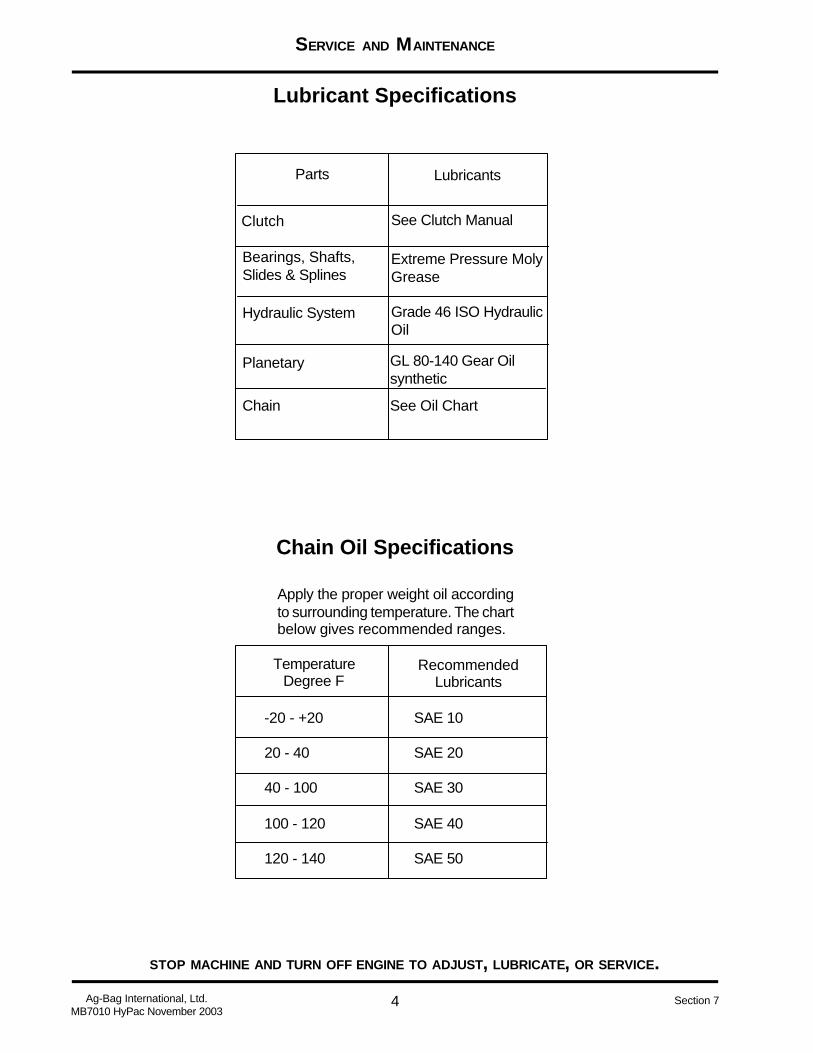
4
SERVICE AND MAINTENANCE
STOP MACHINE AND TURN OFF ENGINE TO ADJUST, LUBRICATE, OR SERVICE.
Ag-Bag International, Ltd.MB7010 HyPac November 2003
Section 7
Lubricant Specifications
Chain Oil Specifications
-20 - +20 SAE 10
20 - 40 SAE 20
40 - 100 SAE 30
100 - 120 SAE 40
120 - 140 SAE 50
TemperatureDegree F
RecommendedLubricants
Apply the proper weight oil accordingto surrounding temperature. The chartbelow gives recommended ranges.
Parts Lubricants
Clutch See Clutch Manual
Bearings, Shafts,Slides & Splines
Extreme Pressure MolyGrease
Hydraulic System Grade 46 ISO HydraulicOil
Planetary GL 80-140 Gear Oilsynthetic
Chain See Oil Chart
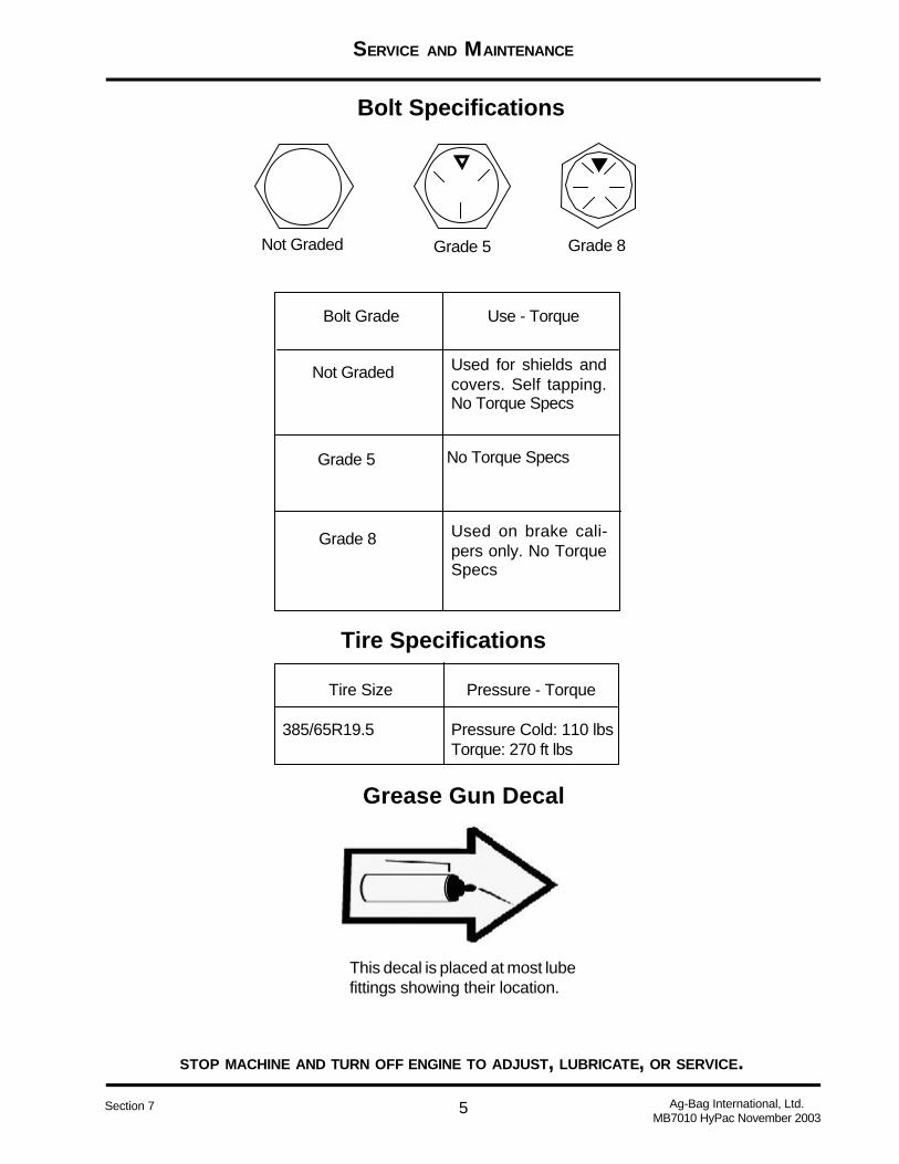
5
SERVICE AND MAINTENANCE
STOP MACHINE AND TURN OFF ENGINE TO ADJUST, LUBRICATE, OR SERVICE.
Ag-Bag International, Ltd.MB7010 HyPac November 2003
Section 7
Bolt Specifications
Grade 5Not Graded Grade 8
Bolt Grade Use - Torque
Not Graded Used for shields andcovers. Self tapping.No Torque Specs
Grade 5
Grade 8 Used on brake cali-pers only. No TorqueSpecs
No Torque Specs
Tire Specifications
Tire Size Pressure - Torque
385/65R19.5 Pressure Cold: 110 lbsTorque: 270 ft lbs
Grease Gun Decal
This decal is placed at most lubefittings showing their location.
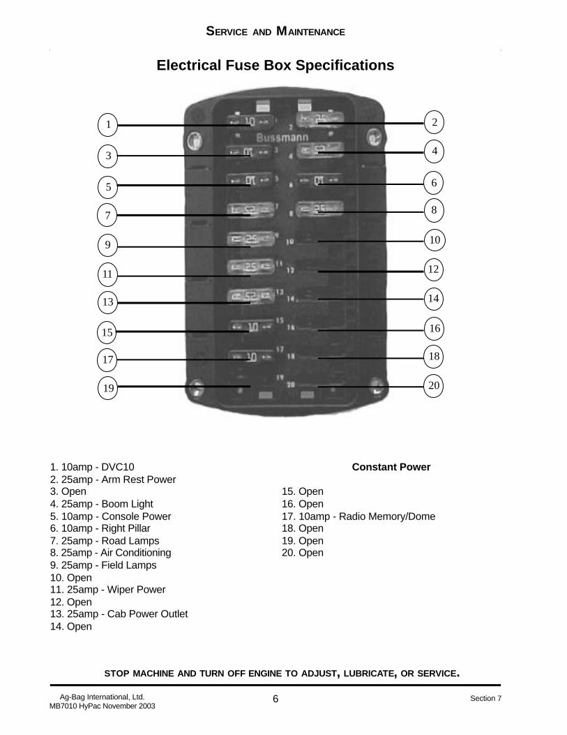
6
SERVICE AND MAINTENANCE
STOP MACHINE AND TURN OFF ENGINE TO ADJUST, LUBRICATE, OR SERVICE.
Ag-Bag International, Ltd.MB7010 HyPac November 2003
Section 7
1 2
3 4
5 6
7 8
9 10
11 12
13 14
15 16
17 18
19 20
Electrical Fuse Box Specifications
1. 10amp - DVC102. 25amp - Arm Rest Power3. Open4. 25amp - Boom Light5. 10amp - Console Power6. 10amp - Right Pillar7. 25amp - Road Lamps8. 25amp - Air Conditioning9. 25amp - Field Lamps10. Open11. 25amp - Wiper Power12. Open13. 25amp - Cab Power Outlet14. Open
Constant Power
15. Open16. Open17. 10amp - Radio Memory/Dome18. Open19. Open20. Open
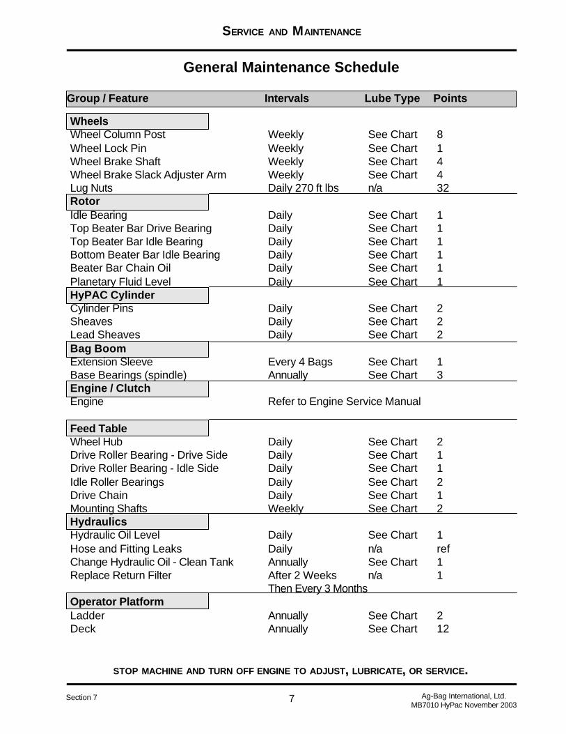
7
SERVICE AND MAINTENANCE
STOP MACHINE AND TURN OFF ENGINE TO ADJUST, LUBRICATE, OR SERVICE.
Ag-Bag International, Ltd.MB7010 HyPac November 2003
Section 7
General Maintenance Schedule
Group / Feature Intervals Lube Type Points
WheelsWheel Column Post Weekly See Chart 8Wheel Lock Pin Weekly See Chart 1Wheel Brake Shaft Weekly See Chart 4Wheel Brake Slack Adjuster Arm Weekly See Chart 4Lug Nuts Daily 270 ft lbs n/a 32RotorIdle Bearing Daily See Chart 1Top Beater Bar Drive Bearing Daily See Chart 1Top Beater Bar Idle Bearing Daily See Chart 1Bottom Beater Bar Idle Bearing Daily See Chart 1Beater Bar Chain Oil Daily See Chart 1Planetary Fluid Level Daily See Chart 1HyPAC CylinderCylinder Pins Daily See Chart 2Sheaves Daily See Chart 2Lead Sheaves Daily See Chart 2Bag BoomExtension Sleeve Every 4 Bags See Chart 1Base Bearings (spindle) Annually See Chart 3Engine / ClutchEngine Refer to Engine Service Manual
Feed TableWheel Hub Daily See Chart 2Drive Roller Bearing - Drive Side Daily See Chart 1Drive Roller Bearing - Idle Side Daily See Chart 1Idle Roller Bearings Daily See Chart 2Drive Chain Daily See Chart 1Mounting Shafts Weekly See Chart 2HydraulicsHydraulic Oil Level Daily See Chart 1Hose and Fitting Leaks Daily n/a refChange Hydraulic Oil - Clean Tank Annually See Chart 1Replace Return Filter After 2 Weeks n/a 1
Then Every 3 MonthsOperator PlatformLadder Annually See Chart 2Deck Annually See Chart 12
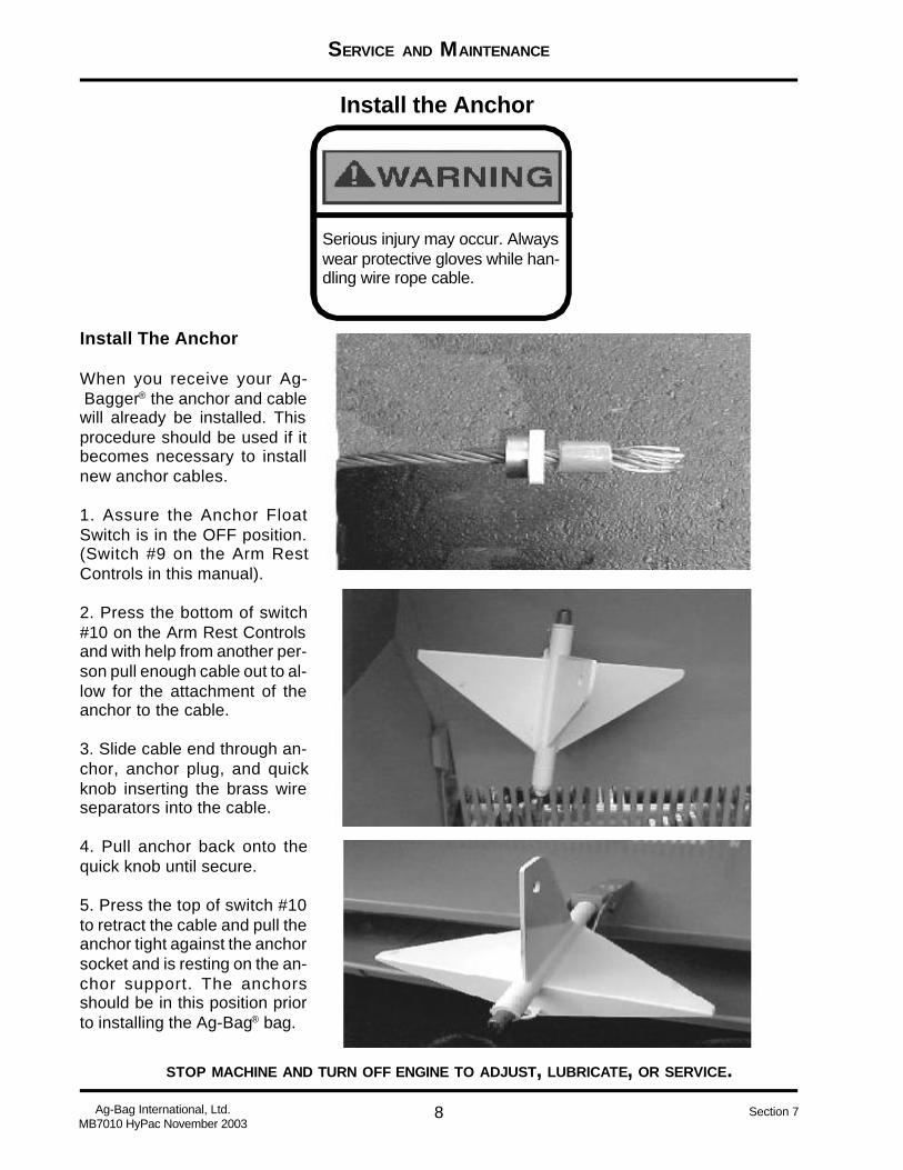
8
SERVICE AND MAINTENANCE
STOP MACHINE AND TURN OFF ENGINE TO ADJUST, LUBRICATE, OR SERVICE.
Ag-Bag International, Ltd.MB7010 HyPac November 2003
Section 7
Install the Anchor
Install The Anchor
When you receive your Ag-Bagger® the anchor and cablewill already be installed. Thisprocedure should be used if itbecomes necessary to installnew anchor cables.
1. Assure the Anchor FloatSwitch is in the OFF position.(Switch #9 on the Arm RestControls in this manual).
2. Press the bottom of switch#10 on the Arm Rest Controlsand with help from another per-son pull enough cable out to al-low for the attachment of theanchor to the cable.
3. Slide cable end through an-chor, anchor plug, and quickknob inserting the brass wireseparators into the cable.
4. Pull anchor back onto thequick knob until secure.
5. Press the top of switch #10to retract the cable and pull theanchor tight against the anchorsocket and is resting on the an-chor support. The anchorsshould be in this position priorto installing the Ag-Bag® bag.
Serious injury may occur. Alwayswear protective gloves while han-dling wire rope cable.
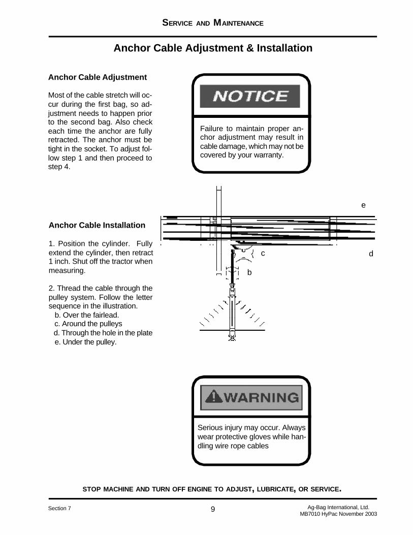
9
SERVICE AND MAINTENANCE
STOP MACHINE AND TURN OFF ENGINE TO ADJUST, LUBRICATE, OR SERVICE.
Ag-Bag International, Ltd.MB7010 HyPac November 2003
Section 7
Anchor Cable Adjustment & Installation
Anchor Cable Adjustment
Most of the cable stretch will oc-cur during the first bag, so ad-justment needs to happen priorto the second bag. Also checkeach time the anchor are fullyretracted. The anchor must betight in the socket. To adjust fol-low step 1 and then proceed tostep 4.
Anchor Cable Installation
1. Position the cylinder. Fullyextend the cylinder, then retract1 inch. Shut off the tractor whenmeasuring.
2. Thread the cable through thepulley system. Follow the lettersequence in the illustration. b. Over the fairlead. c. Around the pulleys d. Through the hole in the plate e. Under the pulley.
Failure to maintain proper an-chor adjustment may result incable damage, which may not becovered by your warranty.
Serious injury may occur. Alwayswear protective gloves while han-dling wire rope cables
b
c d
e
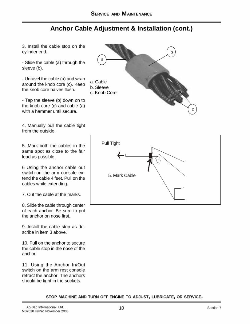
10
SERVICE AND MAINTENANCE
STOP MACHINE AND TURN OFF ENGINE TO ADJUST, LUBRICATE, OR SERVICE.
Ag-Bag International, Ltd.MB7010 HyPac November 2003
Section 7
Anchor Cable Adjustment & Installation (cont.)
3. Install the cable stop on thecylinder end.
- Slide the cable (a) through thesleeve (b).
- Unravel the cable (a) and wraparound the knob core (c). Keepthe knob core halves flush.
- Tap the sleeve (b) down on tothe knob core (c) and cable (a)with a hammer until secure.
4. Manually pull the cable tightfrom the outside.
5. Mark both the cables in thesame spot as close to the fairlead as possible.
6 Using the anchor cable outswitch on the arm console ex-tend the cable 4 feet. Pull on thecables while extending.
7. Cut the cable at the marks.
8. Slide the cable through centerof each anchor. Be sure to putthe anchor on nose first..
9. Install the cable stop as de-scribe in item 3 above.
10. Pull on the anchor to securethe cable stop in the nose of theanchor.
11. Using the Anchor In/Outswitch on the arm rest consoleretract the anchor. The anchorsshould be tight in the sockets.
b
c
a
a. Cableb. Sleevec. Knob Core
5. Mark Cable
Pull Tight

11
SERVICE AND MAINTENANCE
STOP MACHINE AND TURN OFF ENGINE TO ADJUST, LUBRICATE, OR SERVICE.
Ag-Bag International, Ltd.MB7010 HyPac November 2003
Section 7
Feed Table Adjustment
1. Head Roller2. Head Roller Adjustment - Dealer Only3. Grease Points4. Belt Adjuster Points5 Feed Table Wheel Bearings6. Tail Roller7. Feed Table Motor
1
2
3
3
4
4
5
5
6
2
7

12
SERVICE AND MAINTENANCE
STOP MACHINE AND TURN OFF ENGINE TO ADJUST, LUBRICATE, OR SERVICE.
Ag-Bag International, Ltd.MB7010 HyPac November 2003
Section 7
Only trained Dealershould make this adjust-ment. Head Rollershould never need ad-justing.
Feed Table Adjustment (cont.)
Adjust Feed Table Belt
1. Adjustment Bolt2. Adjustment Lock Nut
To adjust belt:- Tighten adjustment bolt to pushbelt away for the side you havetightened.
- Loosen the bolt to bring belt tothe side you have loosened.
Do not over tighten belt, thismay result in premature wearof bearings.
Feed Table Head Roller
1. Head Roller Adjustment Bolt2. Head Roller Adjustment Locknut
1 2
1 2

13
SERVICE AND MAINTENANCE
STOP MACHINE AND TURN OFF ENGINE TO ADJUST, LUBRICATE, OR SERVICE.
Ag-Bag International, Ltd.MB7010 HyPac November 2003
Section 7
Feed Table Adjustment (cont.)
Drive Chain Adjustment
1. Drive Chain2. Feed Table Drive Motor3. Adjustment Lock Nut4. Adjustment Bolt5. Mounting Plate Bolts
Lubricate Chain Daily. See OilSpecification in this manual.
To adjust chain, loosen the fourmounting plate bolts (5) hold-ing the mounting plate. Loosenthe adjustment lock nut (3).Using the adjustment bolt (4)tighten or loosen the chain.There should be NO deflectionin this chain. When you havefinished adjusting chain tightenthe adjustment lock nut (3) andthen the four mounting platebolts (5).
1 2
3 4
5

14
SERVICE AND MAINTENANCE
STOP MACHINE AND TURN OFF ENGINE TO ADJUST, LUBRICATE, OR SERVICE.
Ag-Bag International, Ltd.MB7010 HyPac November 2003
Section 7
Belt Drive Adjustment
33 lbs pressure = lessthan 1” deflection
Rotor Drive Belt Adjustment
The rotor drive belts, drive by theHPTO clutch, drive the rotor.These two belts turn when theclutch is engaged.
The belts tend to stretch after thefirst or second bag. Adjustmentmay be required. Test deflectionfirst (see below). Adjust the en-gine skid to tighten the belts.
1. Mark the nuts to track the num-ber of turns. A large wrench issupplied with your Ag-Bagger® fordoing this adjustment.
2. Loosen nut (B) at each cornerof the engine frame.
3. Turn nut (A) equal number ofturns at each corner of the en-gine frame in the same direction.This will help keep the engine skidlevel. Actual adjustment may onlytake 1/8 to 1/4 turn.
After the first adjustment, thedrive belts should not requiremore adjusting. Follow these ten-sion standards.
- Ideal tension is the lowest ten-sion at which the belt will not slipunder peak load conditions.
- Check tension frequently dur-ing the first 24-48 hours of run-ning the Ag-Bagger®. Make surethe belt is not slipping.
- Over tensioning shortens beltand bearing life.
- Keep belts free from foreignmaterials, which may cause slip-ping.
- Make belt inspection on a peri-odic basis and tighten when slip-ping.
- Never apply belt dressing, asthis will damage the belt andcause early failure.
- For this application, the drivebelt should have a deflection ofless than 1 inch when @ 33 lbsof pressure are applied at themiddle of the span.
B
A
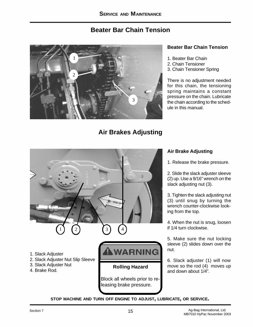
15
SERVICE AND MAINTENANCE
STOP MACHINE AND TURN OFF ENGINE TO ADJUST, LUBRICATE, OR SERVICE.
Ag-Bag International, Ltd.MB7010 HyPac November 2003
Section 7
Beater Bar Chain Tension
Air Brakes Adjusting
Beater Bar Chain Tension
1. Beater Bar Chain2. Chain Tensioner3. Chain Tensioner Spring
There is no adjustment neededfor this chain, the tensioningspring maintains a constantpressure on the chain. Lubricatethe chain according to the sched-ule in this manual.
Air Brake Adjusting
1. Release the brake pressure.
2. Slide the slack adjuster sleeve(2) up. Use a 9/16” wrench on theslack adjusting nut (3).
3. Tighten the slack adjusting nut(3) until snug by turning thewrench counter-clockwise look-ing from the top.
4. When the nut is snug, loosenif 1/4 turn clockwise.
5. Make sure the nut lockingsleeve (2) slides down over thenut.
6. Slack adjuster (1) will nowmove so the rod (4) moves upand down about 1/4”.
Rolling Hazard
Block all wheels prior to re-leasing brake pressure.
1
2
3
1 2 43
1. Slack Adjuster2. Slack Adjuster Nut Slip Sleeve3. Slack Adjuster Nut4. Brake Rod.
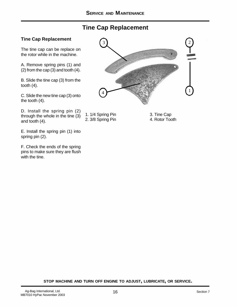
16
SERVICE AND MAINTENANCE
STOP MACHINE AND TURN OFF ENGINE TO ADJUST, LUBRICATE, OR SERVICE.
Ag-Bag International, Ltd.MB7010 HyPac November 2003
Section 7
Tine Cap Replacement
Tine Cap Replacement
The tine cap can be replace onthe rotor while in the machine.
A. Remove spring pins (1) and(2) from the cap (3) and tooth (4).
B. Slide the tine cap (3) from thetooth (4).
C. Slide the new tine cap (3) ontothe tooth (4).
D. Install the spring pin (2)through the whole in the tine (3)and tooth (4).
E. Install the spring pin (1) intospring pin (2).
F. Check the ends of the springpins to make sure they are flushwith the tine.
1
2
4
3
1. 1/4 Spring Pin2. 3/8 Spring Pin
3. Tine Cap4. Rotor Tooth

17
SERVICE AND MAINTENANCE
STOP MACHINE AND TURN OFF ENGINE TO ADJUST, LUBRICATE, OR SERVICE.
Ag-Bag International, Ltd.MB7010 HyPac November 2003
Section 7
Index
A
Adjust Feed Table Belt 12Air Brake Adjusting 14Anchor Cable Installation 9Anchor Cable Adjustment 9
B
Beater Bar Chain Tension 14Bolt Specifications 5
C
Chain Oil Specifications 4
D
Drive Chain Adjustment 13
E
Electrical Fuse Box Specifications 6
F
Feed Table Head Roller 12
G
General Maintenance Schedule 7Grease Gun Decal 5
I
Install The Anchor 8
L
Lubricant Specifications 4
R
Rotor Drive Belt Adjustment 14
S
SpecificationsBolt Specifications 5Chain Oil Specifications 4Lubricant Specifications 4MB7010 HyPac 3Tire Specifications 5
T
Tine Cap Replacement 16Tire Specifications 5

BAGGING INSTRUCTIONS
1 Ag-Bag International, Ltd.MB7010 HyPac November 2003
Appendix C
Appendix C discusses the bagging operation in greater detail than other sections of this manual. It isrecommended that you review this section prior to starting to bag.
AG-BAGGER® MODEL
MB7010 HyPac

BAGGING INSTRUCTIONS
2Ag-Bag International, Ltd.MB7010 HyPac November 2003
Appendix C
Table of Contents
BAGGING INSTRUCTIONS ................................................................................................................ 3
1. THE CROP ....................................................................................................................................... 3
2. BAG LOCATION – PICK AN AREA USING THESE RECOMMENDATIONS: ................................ 3
3. BAG INSTALLATION........................................................................................................................ 3
4. BAGGING PRESSURE.................................................................................................................... 4
5. SEALING AND VENTING – VERY IMPORTANT!! .......................................................................... 4
6. PROTECTION FROM WIND DAMAGE .......................................................................................... 4
7. AG-BAG® BAG MANAGEMENT AND INSPECTION ..................................................................... 4
8. NORMAL USAGE LIFE OF AG-BAG® BAGS ................................................................................. 4
BAG INFORMATION............................................................................................................................ 5
INDEX................................................................................................................................................... 6
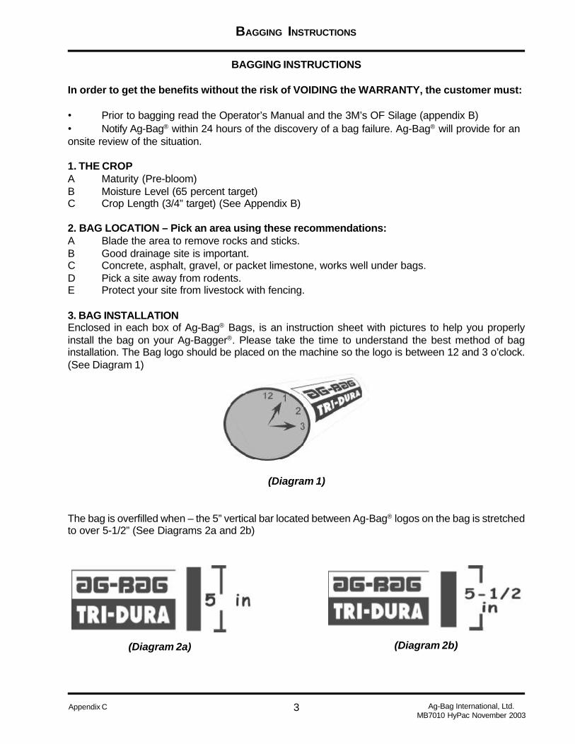
BAGGING INSTRUCTIONS
3 Ag-Bag International, Ltd.MB7010 HyPac November 2003
Appendix C
BAGGING INSTRUCTIONS
In order to get the benefits without the risk of VOIDING the WARRANTY, the customer must:
• Prior to bagging read the Operator’s Manual and the 3M’s OF Silage (appendix B)• Notify Ag-Bag® within 24 hours of the discovery of a bag failure. Ag-Bag® will provide for anonsite review of the situation.
1. THE CROPA Maturity (Pre-bloom)B Moisture Level (65 percent target)C Crop Length (3/4” target) (See Appendix B)
2. BAG LOCATION – Pick an area using these recommendations:A Blade the area to remove rocks and sticks.B Good drainage site is important.C Concrete, asphalt, gravel, or packet limestone, works well under bags.D Pick a site away from rodents.E Protect your site from livestock with fencing.
3. BAG INSTALLATIONEnclosed in each box of Ag-Bag® Bags, is an instruction sheet with pictures to help you properlyinstall the bag on your Ag-Bagger®. Please take the time to understand the best method of baginstallation. The Bag logo should be placed on the machine so the logo is between 12 and 3 o’clock.(See Diagram 1)
(Diagram 1)
The bag is overfilled when – the 5” vertical bar located between Ag-Bag® logos on the bag is stretchedto over 5-1/2” (See Diagrams 2a and 2b)
(Diagram 2a) (Diagram 2b)

BAGGING INSTRUCTIONS
4Ag-Bag International, Ltd.MB7010 HyPac November 2003
Appendix C
4. BAGGING PRESSUREA When filling the bag, is should not be stretched more than 2 inches above the tunnel.B LESS brake press is required when:
1 Bagging up hill2 Bagging with a large tractor or pushing a large truck3 Bagging in muddy or soft sandy soils4 Bagging extremely wet feed (above 75% moisture)5 Bagging dry grains (makes a flatter bag), the bag will not always reach to top oftunnel.6 Bagging oats and winter forages (NOTE: These should only be packet to the top ofthe tunnel because of swelling during storage.)
C MORE brake pressure is required when:1 Bagging on hard surfaces, concrete, asphalt, etc.2 Bagging with motorized Ag-Bagger®
3 Bagging down hill
5. SEALING AND VENTING – Very Important!!As soon as the bag is filled, seal the finished end. As outlined in the instruction sheet. The fasteroxygen is eliminated, the quicker the fermentation process can begin, it is very important to vent thebag. (See Appendix B)
6. PROTECTION FROM WIND DAMAGEWind damage can be caused by wind whipping the loose ends of the Ag-Bag® Bag. To preventdamage, the loose bag end needs to be secured with MasterSeal or by placing tires or other softmaterial on the end of the bag. Wind damage can cause small cracks and eventually wear a hole thatallows air to penetrate, causing feed damage. A tightly secured bag will add to the life of the bag.
7. AG-BAG® BAG MANAGEMENT AND INSPECTIONPeriodic inspection of the bag is essential to maintain an oxygen free environment in the bag. It isrecommended that repairs be made with Ag-Bag® mending tape as soon as they are discovered.
8. NORMAL USAGE LIFE OF AG-BAG ® BAGSRotate stored crops – unpack in same order as packing. Use the oldest feed first.A Ag-Bag® bags located in the U.S.A. along the Canadian border, in all of Canada, NorthernEurope, and in similar climates should be fed within 24 months.B Ag-Bag® bags located in the Central U.S., but more the 500 miles north of the Mexican borderand the Gulf coast, should be fed within 24 months.C Ag-Bag® bags located in extremely hot and sunny regions of the world, such as the southernmost areas of the U.S. and in Mexico, the Caribbean, Middle East, etc., should fed within 12-18months. For more specific recommendations contact you Ag-Bag® Dealer or Ag-Bag® Internationaldirect.

BAGGING INSTRUCTIONS
5 Ag-Bag International, Ltd.MB7010 HyPac November 2003
Appendix C
TD810 8’ x 100’ 1.0 80-90 70 80TD815 8’ x 150’ 1.4 120-140 120 130 3,825TD820 8’ x 200’ 1.9 170-190 164 180 5,294TD913 9’ x 135’ 1.6 140-160 134 150 4,411TD915 9’ x 150’ 1.8 160-180 162 175 6,125TD920 9’ x 200’ 2.2 200-225 205 230 6,765TD1015 10’ x 150’ 2.2 200-220 180 202 5,940TD1020 10’ x 200’ 3.0 270-300 247 278 8,175TD1025 10’ x 250’ 3.6 340-360 324 350 12,250TD1125 11’ x 250’ 4.2 390-420 350 410 14,350TD1225 12’ x 250’ 5.2 490-520TD1230 12’ x 300’ 5.7TD1250 12’ x 500’ 10TD1450 14’ x 500’ 12
NOTE: The tons per bag are approximate and will vary based on moisture and length of chop andcrop types. High moisture shelled corn totals are figured from bagging with a regular Ag-Bag machine.If using an Ag-Bag Grain Bagger, totals will be approximately 20% less, due to density. Also, whenusing the MasterSeal sealing strip you can get approximately 2-4 more loads in the bag, dependingon the size of your bag.
SUGGESTED FEED OUT RATES PER DAY
Winter Rates Summer Rates
Oct. - April May - Sept.Bag Size Feet/Day Tons/Day Feet/Day Tons/Day
8’ 1’ 1 2’ 29’ 1’ 1 2 1/4’ 2 3/4
10’ 2’ 3 2 1/2’ 411’ 2 1/4’ 4 2 3/4’ 512’ 2 1/2’ 5 1/2 3’ 6 1/2
CAPACITY OF TONS PER RUNNING FOOT OF BAG
8’ 1 ton9’ 1 1/4 tons
10’ 1 1/2 tons11’ 1 3/4 tons12’ 2 1/4 tons
BAG INFORMATION
BagCode
BagSize
InoculantIndex
Tons/Bag65%
Earlage
Tons/Bag35%
Shelled Corn
Tons/Bag28-30%Per Bag
Approx.Bushels Per
Bag(Based on 56#
bushel)

BAGGING INSTRUCTIONS
6Ag-Bag International, Ltd.MB7010 HyPac November 2003
Appendix C
Index
B
BAG INFORMATION 5BAG INSTALLATION 3BAG MANAGEMENT AND
INSPECTION 4BAGGING PRESSURE 4
C
CAPACITY OF TONS PERRUNNING FOOT OF BAG 5
CROP 3
I
INSPECTION 4INSTALLATION 3
L
LOCATION 3
M
MANAGEMENT 4
P
PRESSURE 4PROTECTION FROM WIND 4
S
SEALING 4SUGGESTED FEED OUT RATES
5
U
USAGE LIFE 4
V
VENTING 4VOIDING 3
W
WARRANTY 3WIND 4

MANAGEMENT
MATURITY
Moisture
The 3M’s of Silage

2
THE 3M’S OF SILAGE
Appendix BAg-Bag International, Ltd.MB7010 HyPac November 2003
Table of Contents
3M’S OF AG-BAG® SILAGE .................................................................................................................. 3
3M #1 – MANAGEMENT ....................................................................................................................... 3
3M #2 – MATURITY............................................................................................................................... 8
SUGGESTED DAILY FEED OUT RATES.......................................................................................... 10
CUT CROP AT THE PROPER STAGE OF MATURITY......................................................................11
3M #3 – MOISTURE ........................................................................................................................... 13
DAIRY TERMS TO KNOW ................................................................................................................. 15
DAIRY TERMS TO KNOW ................................................................................................................. 17
INDEX ................................................................................................................................................. 18

3
THE 3M’S OF SILAGE
Appendix B Ag-Bag International, Ltd.MB7010 HyPac November 2003
3M’s of AG-BAG® SILAGE
The “3M’s of Ag-Bag® Silage” representdocumented methods and technology of goodsilage making. Ensiling has proven to be the mostefficient method of storing and preserving thenutrient value of your crops. We invite you to benefitfrom proven methods and profit-making concepts.Read on, it can change your future.
THE ART OF MAKINGEXCELLENT SILAGE
1. Silage making is a science, that incorporatesgood management practices. Although manyfactors affect the profitability of a farming operation,forage quality is definitely on of the most important.2. It’s an accepted fact that rapidly fermented, highmoisture feed retains a higher nutrient value thanany other method of harvesting and storing crops.3. By understanding the basics of the fermentationprocess and using good management practices,you can aid nature in achieving a rapid, efficientfermentation, which preserves more of the valuablenutrients in your forage crops.4. By learning how to consistently make excellentsilage, (The silage referred to in this publication isfermentable feed compacted and stored in anairtight Ag-Bag® bag) it can lead to a greaterproduction of meat and milk.5. A good anaerobic fermentation improves thepalatability of feed. The fermentation process usingthe Ag-Bag® system is very similar to the digestionprocess in the first stomach of cattle. Wellfermented silages are a natural feed for cattle. It’svery much like putting your animals on greenpasture year round.
The quality of silage is largely determined by threethings:
Dedication
Preparation
Execution
3M #1 – MANAGEMENT
THE SOIL
The soil should be fertile and pH balanced to insuregood germination. Good soil management alwaysproduces the highest quality crops.
THE SEEDS
High quality seed designed to produce well in yourarea, for length of season and weatherconsiderations are a must. You can’t produce cropsany better than the seeds you plant.
THE ENSILING PROCESS
Silage is a feedstuff resulting from thepreservation of green forage crops by acidification.Acidification is the result of the fermentation of theforage in the absence of oxygen. Research hasproven conclusively that the process of ensilinggreen crops is the most efficient method of storingand preserving the nutritional value of crops forfeeding to ruminant animals. The breaking downof the cellulose and lignin of the plant cells byfermentation helps make the forages moredigestible, thus producing more value. In somecases, the forages are more digestible than greenfeeding or pasturing . All types of forages can befermented and successfully bagged.
FERMENTATION
The miracle of fermentation starts with thebacterias – enzymes – sugars – proteins and anoxygen-free environment.1. Respiration – When a forage plant is harvestedand placed in an Ag-Bag® bag it is alive andtherefore, respiring actively. Even though theforages are packed extremely tight some air isunavoidably trapped in the mass. The oxygen isutilized by the aerobic bacteria existing in the crop,and by the breakdown of sugar in the plant cells.2. Aerobic Fermentation – This phase of theensiling process is called aerobic respiration. Endproducts of this phase of the process are carbondioxide and heat. These reactions are notcomplete and other end products are produced

4
THE 3M’S OF SILAGE
Appendix BAg-Bag International, Ltd.MB7010 HyPac November 2003
such as acetic and butyric acids later used bylactobacilli and streptococci to produce lactic acid.Photolytic enzymes from the plant are also activein this phase, and they break down some of theplant proteins into amino acids. This phase ofrespiration is complete when the oxygen in themass is completely depleted, and the action of theanaerobic microorganisms begin. Aerobicrespiration lasts from 5 to 10 hours under goodstorage conditions.
THE FERMENTATION STARTS
Phase 1 – This is a relatively short phasecharacterized by the beginning of anaerobicmicroorganism activity. The cell contents diffuseout of the cell due to the chopping of the plant, andare used by bacteria clinging to the plant whenplaced in the bag. The formation of acetic andbutyric acids are characteristic of this phase. Thelife of organisms producing these acids is shortdue to the drop in pH produced by their own activity.Phase 2 – This phase is the initiation of the lacticacid fermentation. This activity is well underway atthe end of three days and the establishment of thisactivity completes Phase 2.Phase 3 – Lactic acid production is continued inthis phase and reaches it’s peak which should be3.0 - 13.0 percent of the dry matter and a pH thatis constant at about 4.0. No further changes occur,and the silage is fermented if the pH remainsbetween 4.0 and 4.2 for corn silage, and 4.0 and5.0 for other crops, and no air is allowed to enterthe mass.Phase 4 – This is a stage of quiescence orinactivity. The material has a pH of 4.0 - 4.5 and ifwater and oxygen remain excluded, no furtherchemical changes occur and the material willremain in this preserved state almost indefinitely.Phase 5 – This is an undesirable phase. If the pHdoes not drop below approximately 4.2, or if air isallowed to enter the silage, butyric acid productionis initiated, converting the soluble carbohydratesand lactic previously formed to butyric acid whichis characteristic of spoiled silage. Also, proteinsare broken down to amino acids and these arefurther degraded to other nitrogenous compounds,which may lead to a reduction in a level of digestibleprotein.
FERMENTATION AND INOCULANTS
The general knowledge of the biochemistry andmicrobiology of silage fermentation has increasedtremendously in the last 25 years. Silage is aproduct of anaerobic fermentation. It involves theconversion of water soluble carbohydrates(sugars) to lactic acid, which drops the pH to alevel sufficient to inhibit any further biological activity(change) in the ensiled material when maintainedunder anaerobic conditions.In most circumstances, good silage is achievedby encouraging the dominance of lactic acidbacteria (the good guys), and discouraging theactivity of clostridia and yeast ( the bad guys). Inthe initial stages of ensiling, plant respiratoryenzymes (bad ones) oxidize solublecarbohydrates, resulting in heat production anddecreased amount of sugars available forfermentation.
PRINCIPLES OF ENSILING
Aerobic phase. As crops are put into the bags,two things start to happen: respiration andproteolysis (enzyme action), which are attributedto the activities of plant enzymes. Respiration isthe complete breakdown of a substance to carbondioxide and water, using oxygen. Harvesting of theforage crushes and chops the plant, damaging thecells and releasing many plant enzymes. Some ofthe enzymes, amylase and hemicellulase, breakdown starches, increasing the level of sugars inthe plant. Of these processes, respiration is mostdetrimental to silage quality because:1. Respiration causes a loss of dry matter.2. The plant uses up existing plant sugars duringrespiration. The loss of sugar is crucial at this pointas it affects preservation and nutritional value.Sugars are the principal food for the lactic acidbacteria that ferment the crop and a loss of sugaralso reduces the energy values.3. Prolonged aerobic conditions allow yeasts andmolds to grow to high levels. Large populations ofthese microorganisms can predispose the silageto heating when the bag is opened for feed-out.
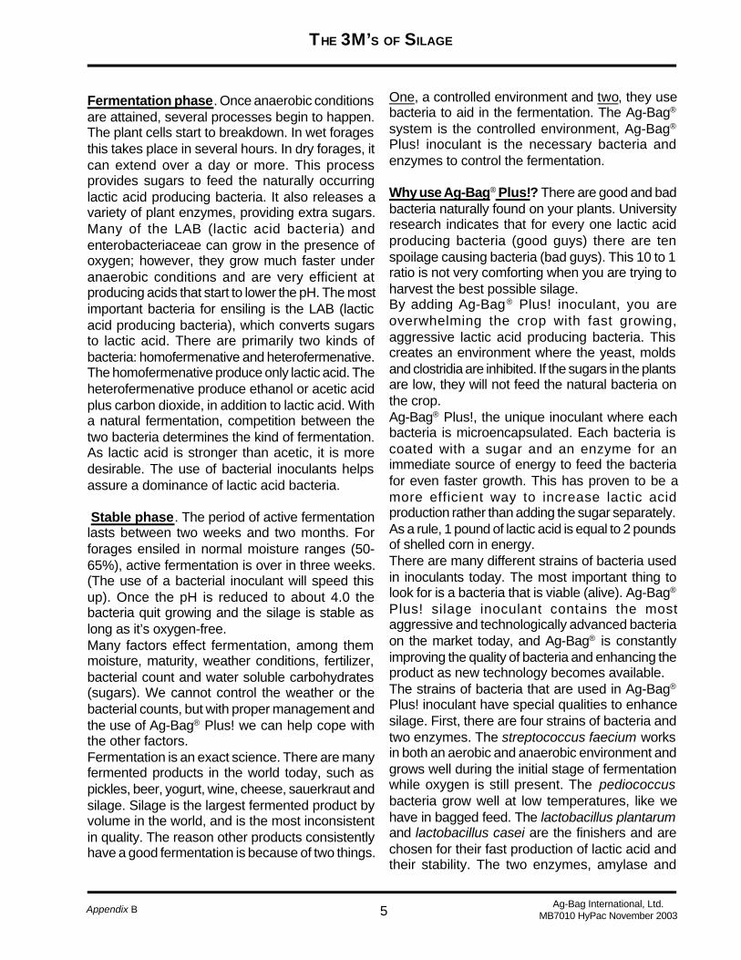
5
THE 3M’S OF SILAGE
Appendix B Ag-Bag International, Ltd.MB7010 HyPac November 2003
One, a controlled environment and two, they usebacteria to aid in the fermentation. The Ag-Bag®
system is the controlled environment, Ag-Bag®
Plus! inoculant is the necessary bacteria andenzymes to control the fermentation.
Why use Ag-Bag® Plus!? There are good and badbacteria naturally found on your plants. Universityresearch indicates that for every one lactic acidproducing bacteria (good guys) there are tenspoilage causing bacteria (bad guys). This 10 to 1ratio is not very comforting when you are trying toharvest the best possible silage.By adding Ag-Bag® Plus! inoculant, you areoverwhelming the crop with fast growing,aggressive lactic acid producing bacteria. Thiscreates an environment where the yeast, moldsand clostridia are inhibited. If the sugars in the plantsare low, they will not feed the natural bacteria onthe crop.Ag-Bag® Plus!, the unique inoculant where eachbacteria is microencapsulated. Each bacteria iscoated with a sugar and an enzyme for animmediate source of energy to feed the bacteriafor even faster growth. This has proven to be amore efficient way to increase lactic acidproduction rather than adding the sugar separately.As a rule, 1 pound of lactic acid is equal to 2 poundsof shelled corn in energy.There are many different strains of bacteria usedin inoculants today. The most important thing tolook for is a bacteria that is viable (alive). Ag-Bag®
Plus! silage inoculant contains the mostaggressive and technologically advanced bacteriaon the market today, and Ag-Bag® is constantlyimproving the quality of bacteria and enhancing theproduct as new technology becomes available.The strains of bacteria that are used in Ag-Bag®
Plus! inoculant have special qualities to enhancesilage. First, there are four strains of bacteria andtwo enzymes. The streptococcus faecium worksin both an aerobic and anaerobic environment andgrows well during the initial stage of fermentationwhile oxygen is still present. The pediococcusbacteria grow well at low temperatures, like wehave in bagged feed. The lactobacillus plantarumand lactobacillus casei are the finishers and arechosen for their fast production of lactic acid andtheir stability. The two enzymes, amylase and
Fermentation phase. Once anaerobic conditionsare attained, several processes begin to happen.The plant cells start to breakdown. In wet foragesthis takes place in several hours. In dry forages, itcan extend over a day or more. This processprovides sugars to feed the naturally occurringlactic acid producing bacteria. It also releases avariety of plant enzymes, providing extra sugars.Many of the LAB (lactic acid bacteria) andenterobacteriaceae can grow in the presence ofoxygen; however, they grow much faster underanaerobic conditions and are very efficient atproducing acids that start to lower the pH. The mostimportant bacteria for ensiling is the LAB (lacticacid producing bacteria), which converts sugarsto lactic acid. There are primarily two kinds ofbacteria: homofermenative and heterofermenative.The homofermenative produce only lactic acid. Theheterofermenative produce ethanol or acetic acidplus carbon dioxide, in addition to lactic acid. Witha natural fermentation, competition between thetwo bacteria determines the kind of fermentation.As lactic acid is stronger than acetic, it is moredesirable. The use of bacterial inoculants helpsassure a dominance of lactic acid bacteria.
Stable phase. The period of active fermentationlasts between two weeks and two months. Forforages ensiled in normal moisture ranges (50-65%), active fermentation is over in three weeks.(The use of a bacterial inoculant will speed thisup). Once the pH is reduced to about 4.0 thebacteria quit growing and the silage is stable aslong as it’s oxygen-free.Many factors effect fermentation, among themmoisture, maturity, weather conditions, fertilizer,bacterial count and water soluble carbohydrates(sugars). We cannot control the weather or thebacterial counts, but with proper management andthe use of Ag-Bag® Plus! we can help cope withthe other factors.Fermentation is an exact science. There are manyfermented products in the world today, such aspickles, beer, yogurt, wine, cheese, sauerkraut andsilage. Silage is the largest fermented product byvolume in the world, and is the most inconsistentin quality. The reason other products consistentlyhave a good fermentation is because of two things.
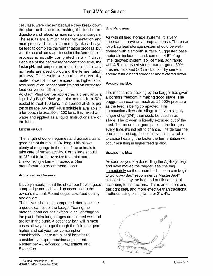
6
THE 3M’S OF SILAGE
Appendix BAg-Bag International, Ltd.MB7010 HyPac November 2003
cellulase, were chosen because they break downthe plant cell structure, making the feed moredigestible and releasing more natural plant sugars.The results are a much faster fermentation andmore preserved nutrients. It normally takes 21 daysfor feed to complete the fermentation process, butwith the use of our silage inoculant the fermentationprocess is usually completed in 5 - 7 days.Because of the decreased fermentation time, thefaster pH, and temperature reduction, not as manynutrients are used up during the fermentationprocess. The results are more preserved drymatter, lower pH, lower temperature, higher lacticacid production, longer bunk life and an increasedfeed conversion efficiency.Ag-Bag® Plus! can be applied as a granular or aliquid. Ag-Bag® Plus! granular comes in a 50#bucket to treat 100 tons. It is applied at ½ lb. perton of forage. Ag-Bag® Plus! soluble is available ina foil pouch to treat 50 or 100 tons. It is mixed withwater and applied as a liquid. Instructions are onthe labels.
LENGTH OF CUT
The length of cut on legumes and grasses, as agood rule of thumb, is 3/4" long. This allowsplenty of roughage in the diet of the animals totake care of rumen activity. Corn silage shouldbe ½" cut to keep oversize to a minimum.Unless using a kernel processor. Seemanufacturer’s recommendations.
ADJUSTING THE CHOPPER
It’s very important that the shear bar have a goodsharp edge and adjusted up according to theowner’s manual. Round edges cost feed qualityand dollars.The knives should be sharpened often to insurea good clean cut of the forage. Tearing thematerial apart causes extensive cell damage tothe plant. Extra long forages do not feed well andare left in the bunk. A set shear bar, will in mostcases allow you to go through the field one gearhigher and cut your fuel consumptionconsiderably. There are a lot of benefits toconsider by proper machine adjustment.Remember – Dedication, Preparation, andExecution.
BAG PLACEMENT
As with all feed storage systems, it is veryimportant to have an appropriate base. The basefor a bag feed storage system should be well-drained with a smooth surface. Suggested basematerials include – sand, cement, 4-5” of aglime, geoweb system, soil cement, agri fabricwith 4-5” of crushed stone, road re-grind, 50%crushed rock and 50% rock dust, dry cementspread with a hand spreader and watered down.
PACKING THE BAG
The mechanical packing by the bagger has givena lot more freedom in making good silage. Thebagger can exert as much as 15,000# pressureas the feed is being compacted. Thiscompaction allows the silage to have a slightlylonger chop (3/4") than could be used in pitsilage. The oxygen is literally extruded out of thefeed. This insures a good pack on the foragesevery time, it’s not left to chance. The denser thepacking in the bag, the less oxygen is availableto cause heating, the faster the fermentation willoccur resulting in higher feed quality.
SEALING THE BAG
As soon as you are done filling the Ag-Bag® bagand have moved the bagger, seal the bagimmediately so the anaerobic bacteria can beginto work. Ag-Bag® recommends MasterSeal®plastic strip. Lay the bag end out flat and sealaccording to instructions. This is an effluent andgas tight seal, and more effective than traditionalmethods using baling twine or 2’ x 4’s.

7
THE 3M’S OF SILAGE
Appendix B Ag-Bag International, Ltd.MB7010 HyPac November 2003
VENTING THE BAG
Some feeds produce a large amount of nitrogenousoxide. This creates a gas from the respiration ofthe plants in the bag. It’s a perfectly normalprocess. In order for the gases to escape undercontrolled conditions, venting is a very importantstep in bagging. For that purpose, Ag-Bag®
recommends and sells reusable vent valvesinstead of cutting exhaust ports that you must latertape shut.
Instructions for using the Ag-Bag® vent valve:Take the cover off the vent tool. Insert the tool, withprongs up, into the cover by lining up the notches.Taking the threaded side of the valve, line up thenotches and slide it over the top of the prongedend of the tool. (See illustration below.)
After you have located the spot where you wantthe vent to be installed, press the prongs of thetool into the plastic to create a hole. Push the toolthrough the hole and pull out leaving the threadedend sticking out. (See illustration below.)
Slide the lid open enough to allow the gases toescape. Within 1-2 days, close lid and leave valvein until that end of the bag is fed out. NOTE: Ifexceptional gassing up occurs, you may leave thevent open for an additional day. Or, if you noticethe bag puffing up again after shutting the valve,open up again until the gases recede, then close.
Turning the valve lid to the left, screw on tightly.(See illustration below.)
BANK YOUR BAGS
To avoid wind damage, use old rubber tires or otherweighted material at the ends of the bag to keeploose plastic from flapping in the wind. The windcan cause plastic fatigue leaving small holes toallow oxygen to enter the feed. A little extra care atthe start can make a difference in the feed quality- hold that loose plastic down.
DO’S AND DON’TS1. DON’T get dirt in the feed going into the bag.2. DON’T allow holes or damage to the bags to
remain open.3. DON’T place bags in a poorly drained area.4. DON’T allow dogs, cats and other animals to
get on the bags.5. DON’T put feed up too dry or too mature.6. DON’T put excessively wet forage in the bag.7. DON’T allow the bagging machine to remain
hooked up to the bag for long periods of time with feed still left in the hopper or
tunnel.
1. DO protect the storage area from livestock.2. DO inspect on a regular basis and mend holes
with Ag-Bag® tape.3. DO place bags on a well-drained, hard, level
surface.4. DO have your feed tested – to be able to mix
and balance your ration.5. DO ensile your crop at proper moisture and
maturity.

8
THE 3M’S OF SILAGE
Appendix BAg-Bag International, Ltd.MB7010 HyPac November 2003
6. DO number and date bags for ease of testingand recall of material ensiled.
7. DO place bags in accessible area for easyfeed removal.
8. DO place bags side-by-side for blending offeeds.
9. DO remove more than 1' of feed per day fromthe face of the bag to prevent aerobic instabilityand heating problems.
3M #2 – MATURITY
HEAD CHOP GRAINS
A new process to harvest grains pioneered by Ag-Bag® International and their satisfied users is “headchopping” small grains using a “direct cut” headon a forage harvester and cutting off the top 4" ofthe plant. This allows the grower to make a highenergy and a high moisture feed. At the time ofharvest the grain is in the heavy dough stage andis still green.Set the chopper on finest chop available and ifpossible use a recut screen and/or kernelprocessor to further (mill) the grain. This head chopgrain feed will be within ½% of full protein of drygrain, it will have TDN from 64%-72% and will addabout 12% fiber to your feeding rations. (Anexcellent way to harvest grain without the use of acombine.) It is recommended to use Ag-Bag® Plus!on this feed. The moisture level is low and requiresthe added bacteria to give a longer shelf life uponopening and feeding.
SNAPPED EARLAGE
This method of harvest allows you to snap the earsof the corn plant, cob and all. It’s then run throughthe chopper with a recutter screen and/or kernelprocessor to process the feed to be put directlyinto the Ag-Bag® bag and should be fermentedwithout further grinding of the grain.The moisture level will be between 30-45% andmay require the application of Ag-Bag® Plus!inoculant to speed up the fermentation of thesnapped earlage. This helps slow down aerobicdeterioration after opening the bag. It’s then readyto feed to your animals after the 21-dayfermentationcycle. If Ag-Bag Plus is used, the grain will be ready
to feed in a shorter time of 7-10 days.
FEEDING OUT OF THE BAG
Because of a higher residual sugar content inbagged feed, aerobic deterioration will occur if thebag is left open. It happens with all silage as it isexposed to oxygen. The small face of the bag givesyou better feed out control.Cut the Ag-Bag® bag open down the top center ofthe bag and lay it out flat on the ground. Moving theloader to one end of the plastic, drive loader tiresonto the plastic using it as a base. With the loaderbucket, loosen the silage starting at the top of thebag. As it loosens and falls on the plastic, use theloader bucket to scoop it up. Keeping the loaderbucket as close to the ground as you can whilenot disturbing the plastic on the ground. The plasticwill work to keep the silage from spilling. As youcontinue to remove the feed from the bag, shakethe remaining feed to the center of the plastic.Operators can easily be trained in the proper feed-out techniques recommended by Ag-Bag® andminimize blowing plastic and feedout loss. (Seediagram on pg.12)The bag should be sized to fit your operation.Minimum daily face removal should be at least 1foot back into the bag each day after opening. Thiswill prevent heating of the feed from oxygenbreakdown. For specific feeding rates, please viewthe chart below to estimate the tons of feed youneed to use each day.Harvesting at the right stage of maturity, harvest toget optimum total digestive nutrients (TDN), andharvest crops that average between 60-70% TDNis ideal to get maximum milk or meat productionper acre.
WHAT S THE VALUE OF CORN SILAGE?
Some universities and research centers say thatcorn harvested as mature corn silage is the kingof all crops as far as producing the most poundsof TDN per acre. A 20-ton-per-acre crop of cornsilage, which would be near an equivalent of a 120bushel an acre grain crop, would produce about 6tons of dry matter per acre.

9
THE 3M’S OF SILAGE
Appendix B Ag-Bag International, Ltd.MB7010 HyPac November 2003
Proper Bag Feed Out TechniqueFor Large Operations
AT WHAT MATURITY DO WE CUT ALFALFA?
Cut when the plant still is over 20 percent protein.This is no later than the late bud stage (before anyflowers appear). Go to the field and grab thatflowering point. You can tell when the bud is gettingvery hard. In fact, at the very late stage you actuallycan see that small, little will become the flower.Start as early as midbud if you have a lot of hay toput in, especially with first crop. Once blossomsshow, quality drops off very rapidly. Don’t wait untilthe perfect time...it never seems to come. If it isn’training and the weather looks acceptable, go aheadand cut.
! Cut the Ag-Bag bag open down the top center of the bag and lay it out flat on the ground.
Prevent the plastic from hangingup in the loader bucket, drive the frontwheels onto the plastic.
! Tip the top of pile. This willloosen it up.
Lower the bucket 1 inch above the plastic.
! Skim doze directlyfrom the front.
! Lift the plastic edges and shake product back to the center of the bag.

10
THE 3M’S OF SILAGE
Appendix BAg-Bag International, Ltd.MB7010 HyPac November 2003
Summer Rates - May - SeptemberBag Size Feet/Day Tons/Day8' 2' 29' 2-1/4' 2-3/410' 2-1/2' 411' 2-3/4' 512' 3' 6-1/2
Winter Rates - October - April Bag Size Feet/Day Tons/Day 8' 1' 1 9' 1' 1-1/4 10' 2' 3 11' 2-1/4' 4 12' 2-1/2' 5-1/2
Suggested Daily Feed Out Rates
Bag Capacity Per Running Foot
Bag Size Tons8' 19' 1-1/410' 1-1/211' 1-3/412' 2-1/4
SUGGESTED DAILY FEED OUT RATES
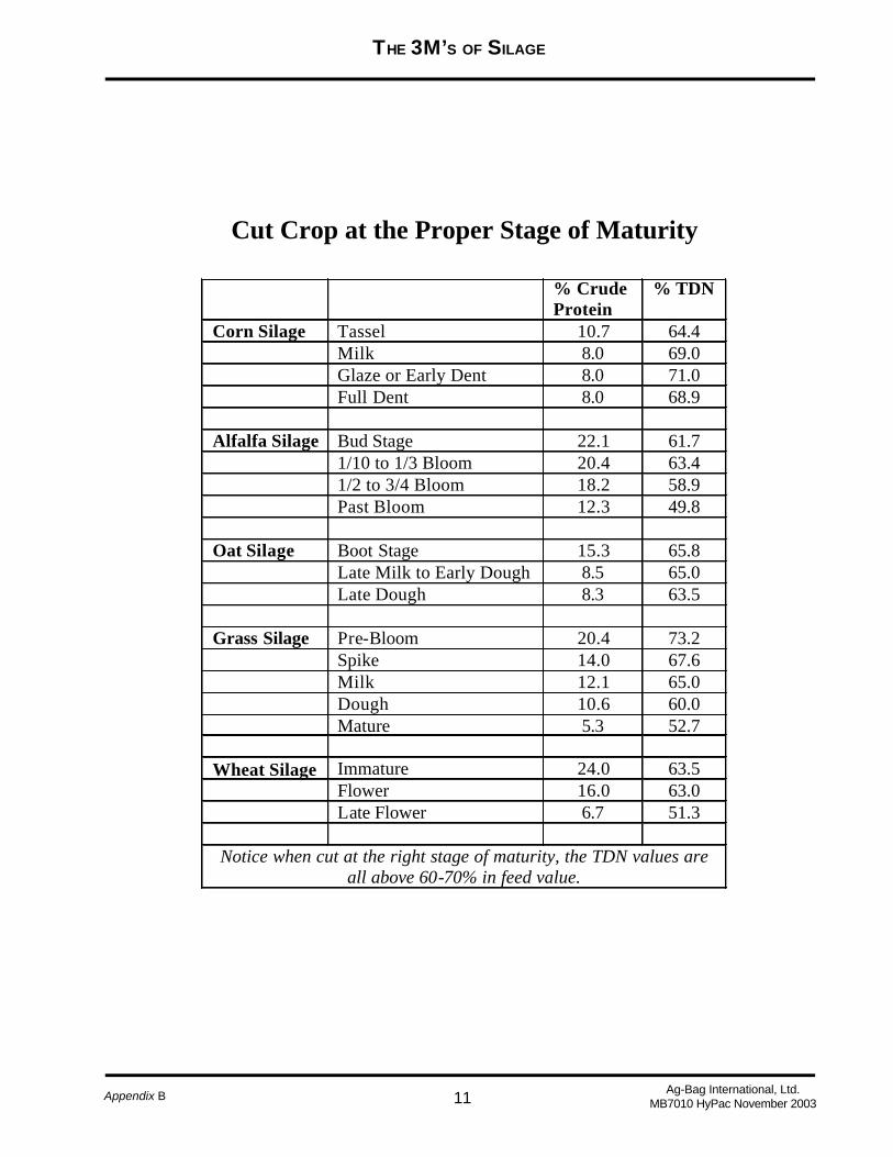
11
THE 3M’S OF SILAGE
Appendix B Ag-Bag International, Ltd.MB7010 HyPac November 2003
% Crude Protein
% TDN
Corn Silage Tassel 10.7 64.4 Milk 8.0 69.0 Glaze or Early Dent 8.0 71.0 Full Dent 8.0 68.9 Alfalfa Silage Bud Stage 22.1 61.7 1/10 to 1/3 Bloom 20.4 63.4 1/2 to 3/4 Bloom 18.2 58.9 Past Bloom 12.3 49.8 Oat Silage Boot Stage 15.3 65.8 Late Milk to Early Dough 8.5 65.0 Late Dough 8.3 63.5 Grass Silage Pre-Bloom 20.4 73.2 Spike 14.0 67.6 Milk 12.1 65.0 Dough 10.6 60.0 Mature 5.3 52.7 Wheat Silage Immature 24.0 63.5
Flower 16.0 63.0 Late Flower 6.7 51.3
Notice when cut at the right stage of maturity, the TDN values are all above 60-70% in feed value.
Cut Crop at the Proper Stage of Maturity
CUT CROP AT THE PROPER STAGE OF MATURITY
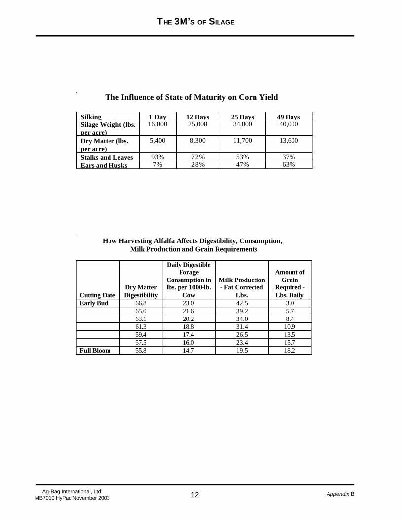
12
THE 3M’S OF SILAGE
Appendix BAg-Bag International, Ltd.MB7010 HyPac November 2003
How Harvesting Alfalfa Affects Digestibility, Consumption, Milk Production and Grain Requirements Cutting Date
Dry Matter Digestibility
Daily Digestible Forage
Consumption in lbs. per 1000-lb.
Cow
Milk Production - Fat Corrected
Lbs.
Amount of
Grain Required - Lbs. Daily
Early Bud 66.8 23.0 42.5 3.0 65.0 21.6 39.2 5.7 63.1 20.2 34.0 8.4 61.3 18.8 31.4 10.9 59.4 17.4 26.5 13.5 57.5 16.0 23.4 15.7 Full Bloom 55.8 14.7 19.5 18.2
The Influence of State of Maturity on Corn Yield Silking 1 Day 12 Days 25 Days 49 Days Silage Weight (lbs. per acre)
16,000 25,000 34,000 40,000
Dry Matter (lbs. per acre)
5,400 8,300 11,700 13,600
Stalks and Leaves 93% 72% 53% 37% Ears and Husks 7% 28% 47% 63%

13
THE 3M’S OF SILAGE
Appendix B Ag-Bag International, Ltd.MB7010 HyPac November 2003
3M #3 – MOISTURE
Ag-Bag® International recommends that foragesbe harvested at moisture levels ranging from 55-68%. This insures best fermentation anddigestibility of TDNs. Wilting of most forages willbe necessary to attain the desired moisture.Note: For round or square bale silage, werecommend 45-55% moisture. Head chop grainshould be harvested in the 30-40% moisture range.Snapped Earlage should be in the 30-45%moisture range. High moisture shelled corn shouldbe in the 28-30% moisture range. One (1) ton ofdry hay will equal three (3) tons of baglage (Ruleof Thumb).
MOISTURE AND QUALITY
In addition to stage of maturity at the time ofharvest, moisture (either too much or too little) isone of the most important factors that determinesthe quality of the final product of the ensilingprocess. Other things being equal, losses withwilted silage are much lower than when the foragesare ensiled as direct cut material at high moisturelevels. Silage cut above 70% moisture tends toincrease the amount of clostridia in the forages.The clostridia starts to use up the proteins andsoluble sugars, lessening the quality of the feed.This higher moisture feed can cause someacidosis in the cattle - since ensiling bacteria aremore active in wetter feeds as the moisture wilt.Try to start bagging at 70% moisture (as soon as itdoesn’t make water) and balance your swathingwith speed of bagging and hauling.
MOISTURE TESTING
There are lots of moisture testers on the markettoday. Some are electronic, others have probes,some cook the moisture out of the feed and leavethe residue to weigh for accurate dry matter.Contact Ag-Bag® International for ordering amoisture tester. Another method used by someexperienced Ag-Bag® users is the Squeeze BallTest. To do this, grab a handful of chopped materialand form a ball. Squeeze the material hard for 30seconds. If you squeeze water out of the feed, it isabove 75% moisture. If no water comes out when
pressed and the material holds a tight ball andsome moisture remains on your hand, it is from65-70% moisture. If the ball comes apart slowly, itis close to 60% moisture. Under 50% moisture,the ball springs apart and does not stay together.Below this level (50-55%), the moisture is gettingmarginal for good fermentation.
DIRECT CUT
Some forages can be cut directly off the stump.EXAMPLE: a) An alfalfa crop that is very grassy orpast 10-20% bloom. b) Most crops that are maturerather than very lush and young. c) Most graincrops in the dough stage can be direct cut if youare going to use whole plant or make Head Chop.For best results and better control of your moisturelevel in the various forage crops, it is best to swathand wilt. The ideal moisture level is 65-68% inforages and in corn silage. In colder climates it isadvisable to lower the moisture level to 55-60%for those bags to be fed in extremely cold weather.
PLANNING YOUR MOISTURE
It requires some experience to maintain swatherdistance ahead of the chopper. There are manyvariables, i.e., First Cut, wet ground, doesn’t dryout as rapidly, rainy conditions. Second Cut, hotand dry, may only require 2-3 hours wilt. Try to startbagging at 70% moisture (as soon as it doesn’tmake water) and balance your swathing with speedof bagging and hauling.

14
THE 3M’S OF SILAGE
Appendix BAg-Bag International, Ltd.MB7010 HyPac November 2003
THE BEST BAG TO USE
Ag-Bag® ’s bag is engineered to be the mostscientifically prepared to deal with all the elements.The bag is made frompolyethylene resins withultraviolet inhibitors andspecial whiteners.Tri-extruded, or bonded,together in 3 layers, thebag’s white outer layer isextreme white to reflectthe heat of the sun. In thislayer are specialultraviolet inhibitors togive long life against thesun’s rays. The clearinner layer is added forstrength and elasticity.
B a g C o d e
B a g S i z e
B a g s P e r B o x
B a g s P e r P a l l e t
I n o c u l a n t I n d e x * B a s e d o n 1 0 0 T o n )
R a n g e o f T o n s / B a g 6 5 % M . A l f a l f a
R a n g e o f T o n s / B a g 3 5 % M . E a r l a g e
R a n g e o f T o n s / B a g 2 8 -3 0 % M . S h e l l e d C o r n
A p p r o x. 5 6 # B u s h e l s p e r B a g
T D 8 1 0 8 ' x 1 0 0 ' 1 1 6 1 .0 8 0 - 9 0 7 0 - 8 0 8 0 -9 0 T D 8 1 5 8 ' x 1 5 0 ' 1 1 2 1 .4 1 2 0- 1 4 0 1 2 0- 1 3 0 1 3 0 -1 4 0 3 , 8 2 5 T D 8 2 0 8 ' x 2 0 0 ' 1 1 0 1 .9 1 7 0- 1 9 0 1 6 4- 1 8 0 1 8 0 -2 0 0 5 , 2 9 4 T D 9 1 3 9 ' x 1 3 5 ' 1 1 2 1 .6 1 4 0- 1 6 0 1 3 4- 1 5 0 1 5 0 4 , 4 1 1 T D 9 1 5 9 ' x 1 5 0 ' 1 1 2 1 .8 1 6 0- 1 8 0 1 6 2 1 7 5 6 , 1 2 5 T D 9 2 0 9 ' x 2 0 0 ' 1 1 0 2 .2 2 0 0- 2 2 5 2 0 5 2 3 0 6 , 7 6 5 T D 1 0 1 5 1 0 ' x 1 5 0 ' 1 1 0 2 .2 2 0 0- 2 2 0 1 8 0 2 0 2 5 , 9 4 0 T D 1 0 2 0 1 0 ' x 2 0 0 ' 1 8 3 .0 2 7 0- 3 0 0 2 4 7 2 7 8 8 , 1 7 5 T D 1 0 2 5 1 0 ' x 2 5 0 ' 1 6 3 .6 3 4 0- 3 6 0 3 2 4 3 5 0 1 2 , 2 5 0 T D 1 1 2 5 1 1 ' x 2 5 0 ' 1 6 4 .2 3 9 0- 4 2 0 3 5 0 4 1 0 1 4 , 3 5 0 T D 1 2 2 5 1 2 ' x 2 5 0 ' 1 6 5 .2 4 5 0- 5 0 0 4 2 0- 4 8 0 4 5 0 1 6 , 0 7 1 T D 1 2 3 0 1 2 ’ x 3 0 0 ’ 1 4 5 .7 5 5 0- 6 0 0 5 0 0- 5 5 0 5 0 0 1 7 , 2 3 8 T D 1 2 5 0 1 2 ’ x 5 0 0 1 2 6 .2 9 8 0 -1 0 0 0 8 4 0- 9 0 0 9 0 0 3 2 , 0 0 0 • M u l t i p l y t h e n u m b e r o f b a g s b y t h e
i n o c u l a n t i n d e x t o d e t e r m i n e t h e n u m b e r o f b u c k e t s o r p o u c h e s o f i n o c u l a n t n e e d e d . E x a m p l e - 2 0 T D 8 1 5 x 1 . 4 = 2 8 b u c k e t s .
N o t e : T o n s p e r b a g a r e a p p r o x i m a t e . W e i g h t s m a y v a r y s l i g h t l y d e p e n d i n g o n m o i s t u r e l e v e l a n d c r o p t y p e s . H i g h m o i s t u r e s h e l l e d c o r n t o t a l s a r e f i g u r e d f r o m b a g g i n g w i t h a s t a n d a r d A g- B a g ® m a c h i n e . I f u s i n g a n A g - B a g ® g r a i n b a g g e r , t o t a l s w i l l b e a p p r o x i m a t e l y 2 0 % l e s s d u e t o d e n s i t y . A l s o , w h e n u s i n g t h e M a s t e r s e a l ® s e a l i n g s t r i p , y o u c a n g e t a p p r o x i m a t e l y 2 - 4 m o r e l o a d s i n t h e b a g , d e p e n d i n g o n t h e s i z e o f y o u r t r u c k s o r w a g o n s .
Insist on using genuine Ag-Bag® bags for the bestfeed quality results.
It is critical to maintain anoxygen-free environment inthe bag. To repair a tear orpuncture in the bag, use therepair tape from Ag-Bag®. Ifa large tear happens, usespray adhesive around thetear area, apply a piece ofused bag over the hole, andseal the patch with repairtape. Careful, periodic bagexaminations will preventspoiled feed. Bagmanagement is a must tomaximize your profits.
15
THE 3M’S OF SILAGE
Appendix B Ag-Bag International, Ltd.MB7010 HyPac November 2003
Acid detergent fiber (ADF): Fiber measurementextracted with acidic detergent in a techniqueemployed to help appraise the quality of forages.Includes cellulose, lignin, ADIN, and acid-insolubleash. ADF is highly correlated with cell walldigestibility. The higher the ADF, the lower thedigestibility or available energy.
Acid detergent insoluble nitrogen (ADIN):Protein or nitrogen that has become chemicallylinked to carbohydrates to form an indigestiblecompound. Also referred to as an insoluble crudeprotein.
Adjusted crude protein (ACP): Protein contentadjusted for the amount of heat-damaged protein.Used in place of CP when ADIN makes up morethan 10% of the CP content of a feed.
Amino acids: Building blocks of proteins. Usedextensively for milk and muscle protein synthesis,as well as glucose synthesis in the liver.
Ammonia: A colorless nitrogen compoundproduced as protein and nonprotein nitrogendegrades or breaks down in the rumen. It can beused to synthesize bacterial protein.
Anion: A negatively charged ion or particle, suchas chloride or sulfate. Anionic salts are nutritionallyimportant in dry cow rations to aid in the preventionof milk fever.
Ash: The mineral matter present in feed. It ismeasured by burning the sample at 500°C until allorganic matter is burned and removed.
Cation: A positively charged ion or particle.
Cellulose: The principle carbohydrate constituentof plant cell membranes. It is made available toruminants through the action of cellulolytic bacteriain the rumen.
Carbohydrates (CHO): Includes the sugars,starch, cellulose, gums, and related substances.Carbohydrates are the largest component in thedairy cow diet and contribute 60 to 70 percent ofthe net energy used for milk production. Theirabbreviation, CHO, indicates that they containcarbon, hydrogen, and oxygen.
Concentrate: A broad classification of feedstuffsthat are high in energy and low in crude fiber (lessthan 18 percent). Included are cereal grains,soybean oil meal, cottonseed meal, and by-products of the milling industry such as corn glutenand wheat bran. A concentrate may be low or richin protein.
Crude fiber (CF): That portion of feedstuffscomposed of polysaccharides such as cellulose,hemicellulose, and lignin. These serve as structuraland protective parts of plants (high in forages andlow in grains). CF is no longer considered a viablemeasurement.
Crude protein (CP): Total protein in a feed. Tocalculate the protein percentage, a feed is firstchemically analyzed for nitrogen content. Sinceproteins average approximately 16 percentnitrogen, the percentage of nitrogen in the analysisis multiplied by 6.25 to give the percent CP.
Degradable intake protein (DIP): Protein ornitrogen that is degraded in the rumen bymicroorganisms and incorporated into microbialprotein or freed as ammonia.
Dry matter (DM): That part of feed which is notwater.
Ensilage: Forage preserved by fermentation in abag, silo, pit, bunker or stack, usually in choppedform. Also called silage.
Fiber: The cellulose portion of roughages (forages)that is low in TDN and hard to digest bymonogastric animals.
DAIRY TERMS TO KNOW

16
THE 3M’S OF SILAGE
Appendix BAg-Bag International, Ltd.MB7010 HyPac November 2003
Forage: The vegetative portion of plants in a fresh,dried, or ensiled state which is fed to livestock.Grasses and legumes cut at the proper stage ofmaturity and stored to preserve quality.
Green chop (fresh forage): Forages harvested(cut and chopped) in the field and fed directly tolivestock. Also called zero grazing or soilage.
Hay: Dried forage (grasses, alfalfa, clovers) usedfor feeding farm animals.
High-moisture silage: Silage containing 70percent or more moisture.
Legume: Clovers, alfalfa, and similar crops thatcan absorb nitrogen directly from the atmospherethrough action of bacteria that live in their rootsand use it as a nutrient for growth.
Lignin: A compound which, with cellulose, formsthe cell walls of plants. It is practically indigestible.
Lipid: Any one of a group of organic substancesthat are insoluble in water though soluble in alcohol,eter, chloroform, and other fat solvents, and havea greasy feel. They are rich sources of dietaryenergy.
Nonprotein nitrogen (NPN): Used by rumenmicroorganisms to synthesize protein.
Neutral detergent fiber (NDF): A measurementof fiber after digesting in a nonacidic, nonalkalinedetergent as an aid in determining quality offorages. Contains the fibers in ADF, plushemicellulose.
Nitrogen balance: Nitrogen in the food consumedminus nitrogen in feces and nitrogen in urine(nitrogen retention).
Nitrogen-free extract (NFE): Consisting ofcarbohydrates, sugars, starches, and a majorportion of materials classed as hemicellulose infeeds. When crude protein, fat, water, ash, andfiber are added and the sum is subtracted from100, the difference is NFE.
Nonfiber carbohydrates: The highly digestiblecarbohydrate fraction of feeds consisting of starch, sugar, and pectin. Subtracting percent (DM basis)NDF, CP, ether extract (fat) and ash from 100provides as estimate of NFC percent in feeds.(NFC%=100 n [%NDF + %CP + %fat + %ash])
Protein equivalent: A term indicating the totalnitrogen content of a substance in comparison withthe nitrogen content of protein (usually plant). Forexample, the nonprotein nitrogen (NPN)compounded, urea, contains approximately 45percent nitrogen and has a protein equivalent of281 percent (6.25 x 45 percent).
Ration: The amount of feed supplied to an animalfor a definitive period, usually 24 hours.
Relative feed value (RFV): Developed primarilyfor use with legume or legume/grass forages, RFVcombines digestibility and intake estimates into onenumber for an easy and effective way to identifyand market quality hay. RFV is expressed as apercent compared to full bloom alfalfa at 100percent RFV.
Roughage: Consists of pasture, silage, hay, orother dry fodder. It may be of high or low quality.Roughages are usually high in crude fiber (morethan 18 percent) and relatively lower in NFE(approximately 40 percent).
Saturated fatty acids: A completely hydrogenatedfat, each carbon atom is associated with themaximum number of hydrogen; there are notdouble bonds. Saturated fatty acids are solid atroom temperature. Tallow is an example of asaturated fat, although approximately 50 percentof the fatty acids are unsaturated. Saturated fatstend to have less detrimental effects on rumenfermentation than unsaturated fats.
Silage: Green forage, such as grass or clover, orfodder, such as field corn or sorghum, that ischopped and compacted into a feed storage bag,silo, or bunker to create an anaerobic or air-freeenvironment and undergoes an acid fermentation(lactic and acetic acids) that retards spoilage.
DAIRY TERMS TO KNOW

17
THE 3M’S OF SILAGE
Appendix B Ag-Bag International, Ltd.MB7010 HyPac November 2003
Total mixed ration (TMR): A blend of all feedstuffs(forages and grains) in one feed. A complete rationthat fits well into mechanized feeding and the useof computers to formulate least-cost rations.
Unsaturated fat: A fat having one or more doublebonds, not completely hydrogenated.
Urea: A nonprotein organic nitrogenous compound.It is made synthetically by combining ammonia andcarbon dioxide.
DAIRY TERMS TO KNOW

18
THE 3M’S OF SILAGE
Appendix BAg-Bag International, Ltd.MB7010 HyPac November 2003
E
Ensilage 15Ensiling Process 3
F
Feeding Out of the Bag 8Fermentation
Aerobic Fermentation 3Respiration 3
Fermentation and Inoculants 4Fermentation Starts 4
Phase 1 4Phase 2 4Phase 3 4Phase 4 4Phase 5 4
Fiber 15Forage 16
G
Green chop (fresh forage) 16
H
Hay 16Head Chop grains 8High-moisture silage 16
L
lactic acid fermentation 4Lactic acid production 4lactobacillus casei 5lactobacillus plantarum 5Legume 16Length of Cut 6Lignin 16Lipid 16
M
Moisture and Quality 13moisture testers 13Moisture Testing 13
Index
Symbols
3M #1 – MANAGEMENT 33M #2 – MATURITY 83M #3 – MOISTURE 133M’s of AG-BAG® SILAGE 3
A
Acid detergent fiber (ADF) 15Acid detergent insoluble nitrogen (ADIN) 15active fermentation 5Adjusted crude protein (ACP) 15Adjusting the Chopper 6aerobic conditions 4aerobic deterioration 8Aerobic Fermentation 3Ag-Bag® Plus! 6Amino acids 15Ammonia 15anaerobic bacteria 6anaerobic microorganism 4Anion 15Ash 15At What Maturity Do We Cut Alfalfa? 9
B
Bag Placement 6Bank Your Bags 7Best Bag to Use 14
C
Carbohydrates (CHO) 15Cation 15Cellulose 15Concentrate 15controlled environment 5Crude fiber (CF) 15Crude protein (CP) 15
D
Dairy Terms to Know 15, 16, 17Degradable intake protein (DIP) 15Direct Cut 13Dry matter (DM) 15

19
THE 3M’S OF SILAGE
Appendix B Ag-Bag International, Ltd.MB7010 HyPac November 2003
N
Neutral detergent fiber (NDF) 16Nitrogen balance 16Nitrogen-free extract (NFE) 16nitrogenous oxide 7Nonfiber carbohydrates 16Nonprotein nitrogen (NPN) 16
P
Packing the Bag 6pH 4Planning Your Moisture 13Principles of Ensiling
Aerobic phase 4Fermentation phase 5Stable phase 5Why use Ag-Bag® Plus!? 5
Protein equivalent 16
R
Ration 16Relative feed value (RFV) 16Respiration 3, 4Roughage 16
S
Saturated fatty acids 16Sealing the Bag 6Seeds 3Silage 3, 16silage 3, 4Snapped Earlage 8Soil 3streptococcus faecium 5
T
total digestive nutrients (TDN) 8Total mixed ration (TMR) 17
U
Unsaturated fat 17Urea 17
V
vent tool 7vent valves 7Venting the Bag 7
W
What s the Value of Corn Silage? 8