
Atmospheric Monitoring system of the JEM … Monitoring system of the JEM-EUSO telescope A....
4
33 RD I NTERNATIONAL COSMIC RAY CONFERENCE,RIO DE JANEIRO 2013 THE ASTROPARTICLE PHYSICS CONFERENCE Atmospheric Monitoring system of the JEM-EUSO telescope A. NERONOV 1 , M. D. RODRIGUEZ FR´ IAS 2 , S. TOSCANO 1 , S. WADA 3 FOR THE JEM-EUSO COLLABORATION. 1 ISDC Data Centre for Astrophysics, Versoix, Switzerland 2 SPace & AStroparticle (SPAS) Group, UAH, Madrid, Spain 3 RIKEN Advanced Science Institute, Japan [email protected] Abstract: The JEM-EUSO fluorescence telescope will observe UV emission from Ultra High Energy Cosmic Ray (UHECR) induced Extensive Air Showers (EAS) from space. Observation with a space-based telescope has an advantage compared to the ground-based observations, because the EAS signal from the upper atmosphere above 10 km altitude (above the top of the Troposphere) is never obscured by optically thick clouds for such a telescope. Nevertheless, proper interpretation of the UV signal from the lower parts of some 60-70% EAS detected by JEM- EUSO, including the reconstruction of the energy, direction and identity of the UHECR particle, requires a detailed knowledge of the influence of clouds and aerosols on the detected UV signal. The Atmospheric Monitoring system of JEM-EUSO will use the LIDAR, operating in the UV band, an infrared camera, the UV images of the night sky obtained by the JEM-EUSO telescope itself, as well as real time global meteorological data and models to deduce the distribution and properties of clouds and aerosol layers in the atmospheric volumes around the location of each triggered EAS event. In this contribution we describe the set-up of JEM-EUSO Atmospheric Monitoring System and characterise its performance. In addition, we show that the reconstruction of UHECR events will be possible also for events occurring in cloudy sky conditions if the data of the Atmospheric Monitoring are taken into account. Keywords: Ultra High Energy Cosmic Rays, Atmospheric Monitoring, IR Camera, LIDAR 1 Introduction JEM-EUSO (the Extreme Universe Space Observatory on- board the Japanese Experiment Module) on the Interna- tional Space Station (ISS) is a new space mission which aims to discover the origin of the Ultra High Energy Cos- mic Rays (UHECRs) with energy above 10 19 eV [1, 2]. It is a refractive telescope with the aperture ’ 2.5 m which it will detect fluorescence UV emission from Extensive Air Showers (EAS) produced by UHECRs penetrating in the atmosphere. The properties of the primary UHECR parti- cles (energy, type, arrival direction) will be derived from the imaging and timing properties of the UV emission from the EAS track in the atmosphere. The amount of both fluo- rescence and Cherenkov signals reaching JEM-EUSO de- pends on the extinction and scattering properties of the at- mosphere. A correct reconstruction of the UHECR energy and of the type of the primary cosmic ray particle requires, therefore, information about absorption and scattering of the UV light. Also, the presence of clouds and aerosols layers will al- ter the physical properties of the atmosphere. Uncertain- ties on the knowledge of extinction and scattering coeffi- cients related to the variable meteorological conditions in- troduce distortions of the UV signal from the EAS leading to systematic errors in the determination of the properties of UHECR from the UV light profiles [3]. In particular, presence of optically thin cloud layers between the EAS and JEM-EUSO telescope reduces the overall inten- sity of UV light leading to an under-estimate of the UHECR energy. EAS penetration into an optically thick cloud pro- duces strong enhancement of the scattered Cherenkov light emission from the shower, which can be misinterpreted as Cherenkov light reflection from the ground/sea. This again Figure 1: Sketch of the concept of Atmospheric Monitoring in JEM-EUSO. leads to a wrong estimate of the depth of the EAS maxi- mum in the atmosphere. Since the ISS is moving with an orbital velocity of ∼ 7 km/sec, JEM-EUSO will experience all possible weather conditions. The AM system will continuously monitor the variable atmospheric conditions in JEM-EUSO Field of View (FoV) during the entire UHECRs data taking period, providing information on cloud cover and optical properties of cloud/aerosol layers at the time and location of the EAS. In this contribution we describe the set up of the AM sys- tem of JEM-EUSO and its expected performance.
Transcript of Atmospheric Monitoring system of the JEM … Monitoring system of the JEM-EUSO telescope A....

33RD INTERNATIONAL COSMIC RAY CONFERENCE, RIO DE JANEIRO 2013THE ASTROPARTICLE PHYSICS CONFERENCE
Atmospheric Monitoring system of the JEM-EUSO telescopeA. NERONOV1, M. D. RODRIGUEZ FRIAS2, S. TOSCANO1, S. WADA3 FOR THE JEM-EUSO COLLABORATION.1 ISDC Data Centre for Astrophysics, Versoix, Switzerland2 SPace & AStroparticle (SPAS) Group, UAH, Madrid, Spain3 RIKEN Advanced Science Institute, Japan
Abstract: The JEM-EUSO fluorescence telescope will observe UV emission from Ultra High Energy CosmicRay (UHECR) induced Extensive Air Showers (EAS) from space. Observation with a space-based telescope has anadvantage compared to the ground-based observations, because the EAS signal from the upper atmosphere above10 km altitude (above the top of the Troposphere) is never obscured by optically thick clouds for such a telescope.Nevertheless, proper interpretation of the UV signal from the lower parts of some 60-70% EAS detected by JEM-EUSO, including the reconstruction of the energy, direction and identity of the UHECR particle, requires a detailedknowledge of the influence of clouds and aerosols on the detected UV signal. The Atmospheric Monitoring systemof JEM-EUSO will use the LIDAR, operating in the UV band, an infrared camera, the UV images of the night skyobtained by the JEM-EUSO telescope itself, as well as real time global meteorological data and models to deducethe distribution and properties of clouds and aerosol layers in the atmospheric volumes around the location ofeach triggered EAS event. In this contribution we describe the set-up of JEM-EUSO Atmospheric MonitoringSystem and characterise its performance. In addition, we show that the reconstruction of UHECR events will bepossible also for events occurring in cloudy sky conditions if the data of the Atmospheric Monitoring are takeninto account.
Keywords: Ultra High Energy Cosmic Rays, Atmospheric Monitoring, IR Camera, LIDAR
1 IntroductionJEM-EUSO (the Extreme Universe Space Observatory on-board the Japanese Experiment Module) on the Interna-tional Space Station (ISS) is a new space mission whichaims to discover the origin of the Ultra High Energy Cos-mic Rays (UHECRs) with energy above 1019 eV [1, 2]. Itis a refractive telescope with the aperture ' 2.5 m which itwill detect fluorescence UV emission from Extensive AirShowers (EAS) produced by UHECRs penetrating in theatmosphere. The properties of the primary UHECR parti-cles (energy, type, arrival direction) will be derived fromthe imaging and timing properties of the UV emission fromthe EAS track in the atmosphere. The amount of both fluo-rescence and Cherenkov signals reaching JEM-EUSO de-pends on the extinction and scattering properties of the at-mosphere. A correct reconstruction of the UHECR energyand of the type of the primary cosmic ray particle requires,therefore, information about absorption and scattering ofthe UV light.Also, the presence of clouds and aerosols layers will al-ter the physical properties of the atmosphere. Uncertain-ties on the knowledge of extinction and scattering coeffi-cients related to the variable meteorological conditions in-troduce distortions of the UV signal from the EAS leadingto systematic errors in the determination of the propertiesof UHECR from the UV light profiles [3].In particular, presence of optically thin cloud layers betweenthe EAS and JEM-EUSO telescope reduces the overall inten-sity of UV light leading to an under-estimate of the UHECRenergy. EAS penetration into an optically thick cloud pro-duces strong enhancement of the scattered Cherenkov lightemission from the shower, which can be misinterpreted asCherenkov light reflection from the ground/sea. This again
Figure 1: Sketch of the concept of Atmospheric Monitoringin JEM-EUSO.
leads to a wrong estimate of the depth of the EAS maxi-mum in the atmosphere.Since the ISS is moving with an orbital velocity of ∼ 7km/sec, JEM-EUSO will experience all possible weatherconditions. The AM system will continuously monitor thevariable atmospheric conditions in JEM-EUSO Field ofView (FoV) during the entire UHECRs data taking period,providing information on cloud cover and optical propertiesof cloud/aerosol layers at the time and location of the EAS.In this contribution we describe the set up of the AM sys-tem of JEM-EUSO and its expected performance.
LIDAR simulation for JEM-EUSO33RD INTERNATIONAL COSMIC RAY CONFERENCE, RIO DE JANEIRO 2013
2 Atmospheric Monitoring systemThe goal of the AM system is to obtain information on thedistribution and optical properties of clouds and aerosollayers inside the JEM-EUSO FoV [5].The basic requirements on the precision of the measure-ments of the clouds and aerosol layers characteristics areobtained from the general requirements on the precision ofmeasurements of the UHECRs properties: (A1) measure-ment of UHECR energy with precision better than 30%;(A2) measurement of the depth of the shower maximumwith precision better than 120 g/ cm2.Since the energy of the UHECR is proportional to theoverall intensity of the UV fluorescence emission fromthe EAS, the uncertainty of the energy measurement (A1)will depend on the uncertainty in the determination of theextinction properties in the atmosphere. Adopting a max-imum 15% uncertainty as a reference value (so that theerror introduced by this uncertainty is sub-dominant), onecan conclude that the measurement of the optical depthprofile of the atmosphere around the EAS location has tobe ∆τ ≥ 0.15.In addition, the depth of the shower maximum will be af-fected by the uncertainty in the determination of the loca-tion and physical properties of clouds and aerosol layers,in such a way that uncertainties in the determination ofboth extinction and scattering properties of these featureswill directly affect the precision of Xmax measurement (A2).Imposing a maximum of 60 g/cm2 as a possible contribu-tion to the uncertainty of Xmax measurement, lead to theconclusion that a measurement of the cloud top with anaccuracy ∆H ≤ 500 m is required.
The AM system will include [4]:
1. an Infrared (IR) camera;
2. a LIght Detection And Ranging (LIDAR) device;
3. global atmospheric models generated from the anal-ysis of all available meteorological data by globalweather services such as the National Centers for En-vironmental Predictions (NCEP), the Global Model-ing and Assimilation Office (GMAO) and the Euro-pean Centre for Medium-Range Weather Forecasts(ECMWF).
The principle of the AM system in JEM-EUSO is illustratedin Fig 1. The JEM-EUSO telescope will observe the EASdevelopment only during nighttime. The IR camera willmonitor the entire FoV to detect the presence of clouds andto obtain the cloud cover and cloud top altitude during theobservation period of the JEM-EUSO main instrument. TheLIDAR will be shot in several directions around the loca-tion of each triggered EAS event and it will measure theoptical depth profiles of the atmosphere in these selected di-rection, with the ranging accuracy of 375/cos(θz) m, whereθz is the angle between the direction of the laser beam andthe nadir. The power of the laser will be adjusted in such away that cloud/aerosol layers with optical depth τ ≥ 0.15at 355 nm wavelength will be detectable.The LIDAR measurements are complementary to the mea-surements taken by the infrared camera. From one hand theIR camera will provide an overall picture of the opticallythick cloud coverage in the JEM-EUSO FoV, which is notpossible to measure with the LIDAR, since this device canretrieve the optical properties of the atmosphere only for a
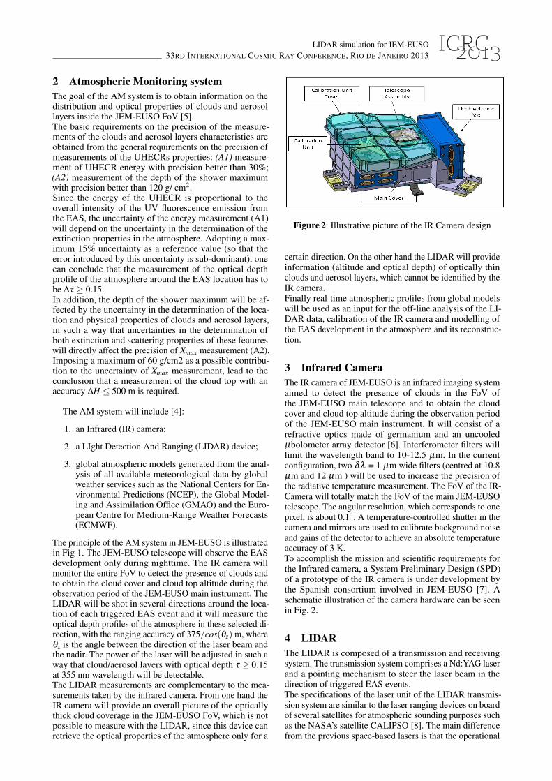
Figure 2: Illustrative picture of the IR Camera design
certain direction. On the other hand the LIDAR will provideinformation (altitude and optical depth) of optically thinclouds and aerosol layers, which cannot be identified by theIR camera.Finally real-time atmospheric profiles from global modelswill be used as an input for the off-line analysis of the LI-DAR data, calibration of the IR camera and modelling ofthe EAS development in the atmosphere and its reconstruc-tion.
3 Infrared CameraThe IR camera of JEM-EUSO is an infrared imaging systemaimed to detect the presence of clouds in the FoV ofthe JEM-EUSO main telescope and to obtain the cloudcover and cloud top altitude during the observation periodof the JEM-EUSO main instrument. It will consist of arefractive optics made of germanium and an uncooledµbolometer array detector [6]. Interferometer filters willlimit the wavelength band to 10-12.5 µm. In the currentconfiguration, two δλ = 1 µm wide filters (centred at 10.8µm and 12 µm ) will be used to increase the precision ofthe radiative temperature measurement. The FoV of the IR-Camera will totally match the FoV of the main JEM-EUSOtelescope. The angular resolution, which corresponds to onepixel, is about 0.1◦. A temperature-controlled shutter in thecamera and mirrors are used to calibrate background noiseand gains of the detector to achieve an absolute temperatureaccuracy of 3 K.To accomplish the mission and scientific requirements forthe Infrared camera, a System Preliminary Design (SPD)of a prototype of the IR camera is under development bythe Spanish consortium involved in JEM-EUSO [7]. Aschematic illustration of the camera hardware can be seenin Fig. 2.
4 LIDARThe LIDAR is composed of a transmission and receivingsystem. The transmission system comprises a Nd:YAG laserand a pointing mechanism to steer the laser beam in thedirection of triggered EAS events.The specifications of the laser unit of the LIDAR transmis-sion system are similar to the laser ranging devices on boardof several satellites for atmospheric sounding purposes suchas the NASA’s satellite CALIPSO [8]. The main differencefrom the previous space-based lasers is that the operational
LIDAR simulation for JEM-EUSO33RD INTERNATIONAL COSMIC RAY CONFERENCE, RIO DE JANEIRO 2013
wavelength (λ = 355 nm) will be the third harmonic of theNd:YAG laser, rather than the first, at 1064 nm, or the sec-ond, at 532 nm, harmonics, as in existing systems. LIDARmeasurements should probe the atmosphere at the locationof each triggered EAS event. To get this information, theLIDAR will have a re-pointing capability. The laser beamwill be repointed in the direction of EAS candidate eventsfollowing each EAS trigger of the JEM-EUSO telescope.Re-pointing of the laser beam will be done with the help ofa steering mirror with two angular degrees of freedom andmaximal tilting angle ±15◦, needed to point the laser beamanywhere within the JEM-EUSO FoV. The laser backscat-tered signal will be received by the main JEM-EUSO tele-scope which is well suited for detection of the 355 nm wave-length. Any Multi-Anode Photo-Multiplier Tube (MAPMT)in the focal surface of JEM-EUSO telescope could tem-porarily serve as the LIDAR signal detector; a special LI-DAR trigger is foreseen in the Focal surface electronics ofJEM-EUSO detector.
A summary of the specifications needed for the entiresystem is reported in table 1.
Parameter SpecificationWavelength 355 nmRepetition Rate 1 HzPulse width 15 nsPulse energy 20 mJ/pulseBeam divergence 0.2 mradReceiver JEM-EUSO telescopeDetector MAPMT (JEM-EUSO)Range resolution (nadir) 375 mSteering of output beam ±30◦ from verticalMass 14 kgDimension 450×350×250 mmPower < 20 W
Table 1: Specification for the JEM-EUSO LIDAR.
Measurements of the laser backscattered signal with timeresolution of 2.5 µs (representing the duration of the timeunit, named Gate Time Unit or GTU, of the pixel-level digi-tal trigger) will provide a range resolution of 375 m in nadirdirection. The energy of the laser pulse will be adjusted insuch a way that the backscattered signal will have enoughstatistics for the detection and measurement of the opticaldepth of optically thin clouds with τ ≤0.15 at large off- axisangles.In order to study the capability of the system in retriev-ing the physical properties of atmospheric features such ascloud and aerosol layers a simulation of the LIDAR hasbeen implemented inside the ESAF Simulation Frameworkused for the JEM-EUSO mission [9]. This simulation chainhas been used to study the features of the LIDAR backscat-tered signal and to reproduce a real-case observation inwhich the EAS profile shows observable deviations fromthe “clear sky case” and needs to be corrected.In fact, once an EAS is detected, LIDAR is used to mon-itor whether the shower developed in clear sky or not. Ifthe presence of a cloud is detected the backscattered signalfrom the laser is used to measure the cloud optical depth.Examples of the simulated laser backscattered signal asit would appear in the JEM-EUSO detector are shown inFig. 3. The top panel shows the comparison of signal in
200
0
200
400
600
800
1000
Rece
ived s
ignal [p
he/G
TU
] Clear skyCloud: top = 7 km, τ = 1
051015202530Altitude [km]
1250 1300 1350 1400Time after shot [µsec]
1012345678
Sca
tteri
ng r
ati
o (
SR
)
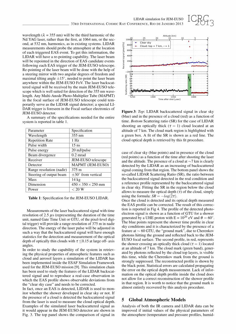
Figure 3: Top: LIDAR backscattered signal in clear sky(blue) and in the presence of a cloud (red) as a function oftime. Bottom Scattering ratio (SR) for the case of LIDARshooting an optically thick (τ = 1) cloud located at analtitude of 7 km. The cloud mark region is highlighted witha green box. A fit of the SR is shown as a red line. Thecloud optical depth is retrieved by this fit procedure.
case of clear sky (blue points) and in presence of the cloud(red points) as a function of the time after shooting the laserand the altitude. The presence of a cloud at∼7 km is clearlydetected by the LIDAR as an increasing of backscatteredsignal coming from that region. The bottom panel shows theso-called LIDAR Scattering Ratio (SR), the ratio betweenthe backscattered signal detected in the real condition anda reference profile represented by the backscattered signalin clear sky. Fitting the SR in the region below the cloudallows to measure the optical depth (τ) of the cloud, simplyusing the formula: SR =−log(2τ).Once the cloud is detected and its optical depth measuredthe EAS profile can be corrected. The result of this correc-tion is reported in Fig 4. The profile of the detected photo-electron signal is shown as a function of GTU for a showergenerated by a UHE proton with E = 1020 eV and θ = 60◦.The blue points represent the shower time profile in clearsky conditions and it is characterized by the presence of afeature at ∼ 60 GTU, the “ground mark”, due to Cherenkovphotons hitting the ground and reflected back to the JEM-EUSO focal surface. The second profile, in red, representsthe shower crossing an optically thick cloud (τ = 1) locatedat an altitude of 7 km. The cloud mark (green band), gener-ated by photons reflected by the cloud top layers, is visiblethis time, while the Cherenkov mark from the ground isstrongly suppressed. The reconstructed profile is shown bythe black point. Statistical errors are calculated propagatingthe error on the optical depth measurement. Lack of infor-mation on the optical depth profile inside the cloud doesnot allow for a correct reconstruction of the shower profilein that region. It is worth to notice that the ground mark isalmost entirely recovered by this analysis procedure.
5 Global Atmospheric ModelsAnalysis of both the IR camera and LIDAR data can beimproved if initial values of the physical parameters ofthe atmosphere (temperature and pressure profiles, humid-

LIDAR simulation for JEM-EUSO33RD INTERNATIONAL COSMIC RAY CONFERENCE, RIO DE JANEIRO 2013
0 10 20 30 40 50 60 70GTU [=2.5 µsec]
0
10
20
30
40
50
60
70
Dete
cted s
ignal [p
he]
cloud mark
groundmark
Shower in clear skyShower in cloud (top = 7 km, τ = 1)
Reconstructed profile
Figure 4: Reconstructed time profile (black points) of 1020
eV EAS together with the clear sky (blue) and cloud affected(red) profiles for an EAS of E = 1020 eV and θ = 60◦.Error bars are statistical only. The loss of information insidethe cloud does not allow for a good reconstruction of theprofile in that region. The ground mark (gray band) is almostentirely recovered by this procedure.
ity, wind speed, etc) in the monitored region are known[10]. Weather forecasting services across the world, such asECWMF [11] in Europe or GMAO [12] and NCEP [13] inUS systematically collect all the available meteorologicaldata (from weather stations, meteorological balloons, satel-lite and aircraft measurements) to use them as input data forthe Global Atmospheric Models (GAM), which are com-puter generated models of atmospheric conditions at the en-tire Earth. The product of the model is an estimation of thestate of the atmosphere, or state variables at any given pointon a latitude-longitude grid and at different times. This cal-culation takes into account the real-time conditions of theatmosphere as boundary condition for the global model. Asresult, data products, e.g. temperature, pressure and humid-ity profiles, are available.Currently some efforts have been made by the collaborationto investigate the possibility of using data from the GlobalData Assimilation System (GDAS) of NCEP [14]. GDASdata have been successfully incorporated in JEM-EUSOsimulation of the air showers, and the final goal is to incor-porate them in the EAS reconstruction analysis and in theanalysis of the data of the LIDAR and IR camera in JEM-EUSO.
6 ConclusionsJEM-EUSO is a next-generation fluorescence telescopewhich will detect UHECRs induced EAS from space. Tocorrectly reconstruct the EAS profile, knowledge of theatmospheric condition at the location of the shower isneeded. The AM system of JEM-EUSO, which includesthe IR camera, the LIDAR and global atmospheric modeldata, will provide sufficient information on the state ofthe atmosphere around the location of EAS events. Thisinformation will be used to correct the profiles of cloud-affected EAS events for the effect of clouds and aerosollayers, so that most of them could be retained for theUHECR data analysis.
References[1] Adams Jr., J.H. et al. (JEM-EUSO Collaboration), An
evaluation of the exposure in nadir observation of theJEM-EUSO mission, Astroparticle Physics, 44, 7690(2013)
[2] P. Picozza, T. Ebisuzaki, A. Santangelo (JEM-EUSOCollaboration) “Status of the JEM-EUSO mission”,ID0738, These Proceedings.
[3] G. Saez- Cano et al., Observation of Ultra-High EnergyCosmic Rays in cloudy conditions by the JEM-EUSOSpace Observatory, Proceedings of 32nd InternationalCosmic Ray Conference (ICRC), Beijing, 3, 231 (2011).(Preprint) Arxiv:1204.5065.
[4] A. Neronov, S. Wada, M.D. Rodriguez Frias et al.,Atmospheric Monitoring System of JEM-EUSO,Proceedings of 32nd International Cosmic RayConference (ICRC), Beijing, 6, 332 (2011). (Preprint)Arxiv:1204.5065.
[5] M.D. Rodrıguez Frıas for the JEM-EUSOCollaboration, The Atmospheric Monitoring System ofthe JEM-EUSO Space Mission. Proc. InternationalSymposium on Future Directions in UHECR Physics,CERN. The European Physical Journal (2012).
[6] J.A. Morales de los Rıos et al., The IR-Camera of theJEM-EUSO Space Observatory, Proceedings of 32ndInternational Cosmic Ray Conference (ICRC), Beijing,11, 466 (2011).
[7] M.D. Rodrıguez Frıas (JEM-EUSO Collaboration),“Towards the Preliminary Design Review of the InfraredCamera of the JEM-EUSO Space Mission” , ID900,These Proceedings.
[8] http://www-calipso.larc.nasa.gov/[9] S. Toscano, L. Valore, A. Neronov, F. Guarino (JEM-
EUSO Collaboration), “LIDAR treatment inside theESAF Simulation Framework for the JEM-EUSOmission”, ID0530, These Proceedings.
[10] B. Keilhauer and M. Will for the AUGERCollaboration, “Description of atmospheric conditionsat the Pierre Auger Observatory using meteorologicalmeasurements and models”, Eur. Phys. J. Plus (2012)127: 96.
[11] http://www.ecmwf.int/[12] http://gmao.gsfc.nasa.gov/[13] http://www.ncep.noaa.gov/[14] http://www.ncdc.noaa.gov/model-data/global-data-
assimilation-system-gdas


![Results from the first missions of the JEM-EUSO program · EUSO–TA is currently taking data since 2015 at the Black Rock Mesa site of the Telescope Array observatory [2]. Two stratospheric](https://static.fdocuments.in/doc/165x107/5ed6652a989ebd4f8f073f11/results-from-the-irst-missions-of-the-jem-euso-program-eusoata-is-currently.jpg)