Atmospheric Corrections - IEEE Power and Energy Society · Introduction to atmospheric corrections...
23
Atmospheric Corrections Johannes Rickmann Phenix Technologies 2014 IEEE PES Panel Session Discussions on IEEE Std.4-2013: High-Voltage Testing Techniques 1
Transcript of Atmospheric Corrections - IEEE Power and Energy Society · Introduction to atmospheric corrections...

Atmospheric Corrections
Johannes RickmannPhenix Technologies
2014 IEEE PES Panel SessionDiscussions on IEEE Std.4-2013: High-Voltage Testing
Techniques
1
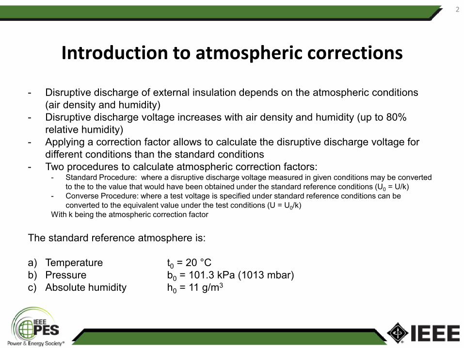
Introduction to atmospheric corrections
- Disruptive discharge of external insulation depends on the atmospheric conditions(air density and humidity)
- Disruptive discharge voltage increases with air density and humidity (up to 80% relative humidity)
- Applying a correction factor allows to calculate the disruptive discharge voltage for different conditions than the standard conditions
- Two procedures to calculate atmospheric correction factors:- Standard Procedure: where a disruptive discharge voltage measured in given conditions may be converted
to the to the value that would have been obtained under the standard reference conditions (U0 = U/k)- Converse Procedure: where a test voltage is specified under standard reference conditions can be
converted to the equivalent value under the test conditions (U = U0/k)With k being the atmospheric correction factor
The standard reference atmosphere is:
a) Temperature t0 = 20 °Cb) Pressure b0 = 101.3 kPa (1013 mbar)c) Absolute humidity h0 = 11 g/m3
2

Definition of atmospheric correction factors
Two methods are in use in IEEE STD 4 to calculate atmospheric correction factors
13.2.1 Atmospheric correction using Method 1 (recommended method for new equipment)
The disruptive discharge voltage is proportional to the atmospheric correction factor k
K = k1k2With k1 air density correction factor
k2 humidity correction factor
13.2.1.1 Air density correction factor, k1
The air density correction factor k1 depends on the relative air density δ and can be generally expressed as:
k1 = δm
where m is an exponent given in 13.2.1.3
3

Definition of atmospheric correction factors
4
Definition of atmospheric correction factors
5

The exponents, m and w, are obtained from Table 9 for the specified ranges of g (Figures 33 and 34)
Table 9 – Values of exponents, m for air density correction and w for humidity correction, as a function of the parameter g
g m w
<0,2 0 0
0,2 to 1,0 g(g-0,2)/0,8 g(g-0,2)/0,8
1,0 to 1,2 1,0 1,0
1,2 to 2,0 1,0 (2,2-g)(2,0-g)/0,8
>2,0 1,0 0
Definition of atmospheric correction factors
6

Definition of atmospheric correction factors
7
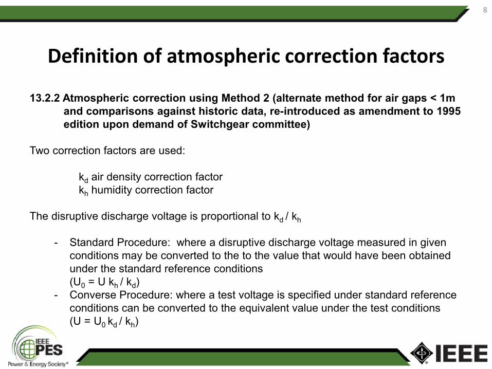
13.2.2 Atmospheric correction using Method 2 (alternate method for air gaps < 1m and comparisons against historic data, re-introduced as amendment to 1995 edition upon demand of Switchgear committee)
Two correction factors are used:
kd air density correction factorkh humidity correction factor
The disruptive discharge voltage is proportional to kd / kh
- Standard Procedure: where a disruptive discharge voltage measured in given conditions may be converted to the to the value that would have been obtained under the standard reference conditions (U0 = U kh / kd)
- Converse Procedure: where a test voltage is specified under standard reference conditions can be converted to the equivalent value under the test conditions (U = U0 kd / kh)
Definition of atmospheric correction factors
8

Definition of atmospheric correction factors
9

Definition of atmospheric correction factors
10

Definition of atmospheric correction factors
11

Definition of atmospheric correction factors
12

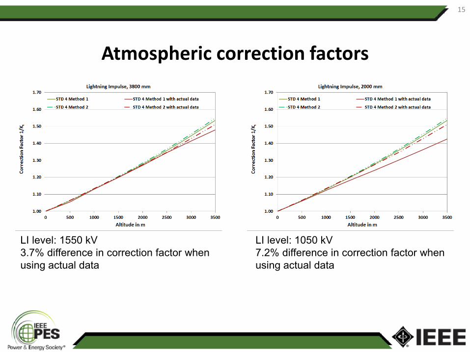
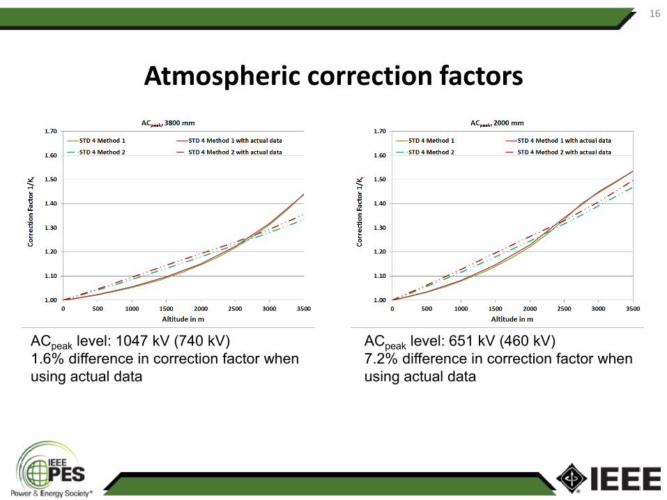
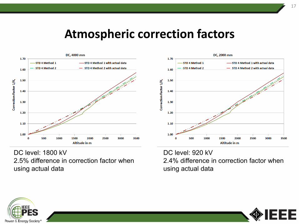
Atmospheric correction factors
Correction curves comparing Method 1 and Method 2 correction factors using only air density correction to those using actual atmospheric data
The curves where calculated for 550 kV equipment (3800 mm discharge path) and 245 kV equipment (2000 mm discharge path)
The actual atmospheric data was taken from the Chinese Standard DL/T620
Altitudem 0 500 1000 1500 2000 2500 3000 3500
Relative air pressure 1 0.945 0.888 0.835 0.786 0.741 0.695 0.655
Relative air density 1 0.955 0.9085 0.865 0.824 0.784 0.745 0.708
Absolute humidity h g/m3 11 9.17 7.64 6.37 5.33 4.42 3.68 3.08
Temperature°C 20 16.9 13.4 9.8 6.5 3.9 0.3 -1.9
13

Atmospheric correction factors
SI level: 1175 kV SI level: 700 kV1.5% difference in correction factor when 2.1% difference in correction factor when using actual data using actual data
14
Atmospheric correction factors
LI level: 1550 kV LI level: 1050 kV3.7% difference in correction factor when 7.2% difference in correction factor when using actual data using actual data
15
Atmospheric correction factors
ACpeak level: 1047 kV (740 kV) ACpeak level: 651 kV (460 kV)1.6% difference in correction factor when 7.2% difference in correction factor when using actual data using actual data
16
Atmospheric correction factors
DC level: 1800 kV DC level: 920 kV2.5% difference in correction factor when 2.4% difference in correction factor when using actual data using actual data
17

ACrms to ACpeak
Correction factors calculated for peak and rms withstand voltage and discharge voltage3800 – 740: rms withstand value for 3800 mm discharge path3800 – 1047: peak withstand value for 3800 mm discharge path3800 – 880: rms withstand value for 3800 mm discharge path3800 – 1245: peak withstand value for 3800 mm discharge path
18

Differences to IEC 60060-1 Ed.3
IEC 60060-1 Ed.3 states for the converse procedure in clause 4.3.3.2“However, as U enters into the calculation of Kt, an iterative procedure might have to be used (see Annex E) For the converse procedure of applying correction factors, where a test voltage is specified for standard reference conditions and must be converted into the equivalent value under the test conditions an iterative procedure is proposed, specially if the correction factor Kt is lower than e.g. 0.95 in order to reduce the error in calculating correction factors for high altitude test sites.
The iteration is continued until
050 )1(1.1)(1.1)( xUixKixUiU tt −==
valuenedpredetermi)1()( <−− tt KiK
19

Differences to IEC 60060-1 Ed.3
Comparison of calculated correction factors for SI for a 3800 mm discharge path at withstand and flashover using the converse procedure with and without the iterative procedureThe differences are about the same for AC but smaller for DC and almost negligible for LI
20

Differences to other Standards• IEC 60071-2
Where:H is the altitude in mm is defined as 1 for LI and short duration AC test voltages and for SI m is to be calculated using the curves below
• IEEE C37.100
Where:m is defined as 1 for LI and short duration AC test voltages and 0.75 for phase to ground SI
21
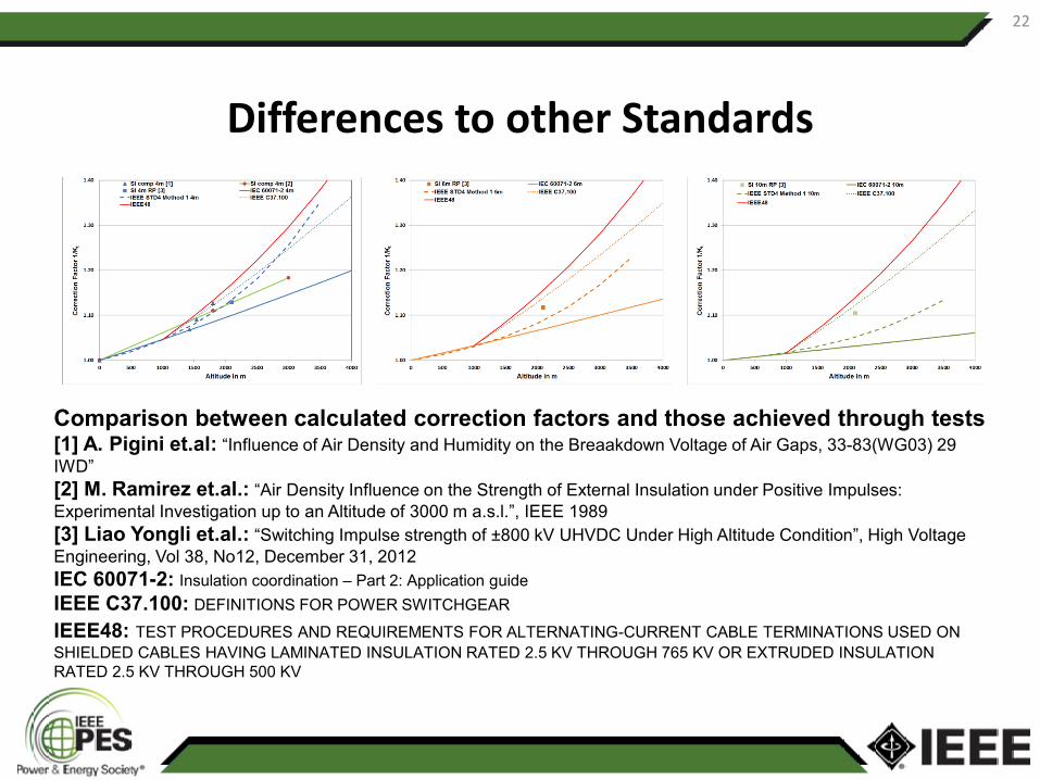
Differences to other Standards
Comparison between calculated correction factors and those achieved through tests[1] A. Pigini et.al: “Influence of Air Density and Humidity on the Breaakdown Voltage of Air Gaps, 33-83(WG03) 29 IWD”[2] M. Ramirez et.al.: “Air Density Influence on the Strength of External Insulation under Positive Impulses: Experimental Investigation up to an Altitude of 3000 m a.s.l.”, IEEE 1989[3] Liao Yongli et.al.: “Switching Impulse strength of ±800 kV UHVDC Under High Altitude Condition”, High Voltage Engineering, Vol 38, No12, December 31, 2012IEC 60071-2: Insulation coordination – Part 2: Application guideIEEE C37.100: DEFINITIONS FOR POWER SWITCHGEAR
IEEE48: TEST PROCEDURES AND REQUIREMENTS FOR ALTERNATING-CURRENT CABLE TERMINATIONS USED ON SHIELDED CABLES HAVING LAMINATED INSULATION RATED 2.5 KV THROUGH 765 KV OR EXTRUDED INSULATION RATED 2.5 KV THROUGH 500 KV
22

Future of Atmospheric Correction Factors
• Due to the large differences in the results using the correction methods of different standards a CIGRE working group was established within the CIGRE Study Committee D1 (Materials and Emerging Test Techniques) and a joint IEC working group JWG22
• D1.50: Atmospheric and altitude corrections factors for air gaps and clean insulators– Members from Australia, Brazil, China, Germany, Italy, Japan, South Africa, Sweden, USA– Tendency is going away from the simplified method having one m over g curve for various arrangements– Tests at higher altitude suggest that the factor m is increasing again at higher altitudes
23