Atmel Microcontroller and C Programming: Simon LED...
27
ATMEL AVR STK500 Atmel Microcontroller and C Programming – Simon LED Light Game Christopher Steiner Florida Gulf Coast University Page | 1 Fall 2009 Atmel Microcontroller and C Programming: Simon LED Game – Final Draft Christopher Steiner Dr. Janusz Zalewski CEN 3213 Fall 2009 - Embedded Systems Programming Florida Gulf Coast University Fort Myers, Florida 12-4-09
Transcript of Atmel Microcontroller and C Programming: Simon LED...
ATMEL AVR STK500 Atmel Microcontroller and C Programming – Simon LED Light Game
Christopher Steiner Florida Gulf Coast University P a g e | 1 Fall 2009
Atmel Microcontroller and C Programming: Simon LED Game – Final Draft
Christopher Steiner
Dr. Janusz Zalewski
CEN 3213 Fall 2009 - Embedded Systems Programming
Florida Gulf Coast University
Fort Myers, Florida
12-4-09

ATMEL AVR STK500 Atmel Microcontroller and C Programming – Simon LED Light Game
Christopher Steiner Florida Gulf Coast University P a g e | 2 Fall 2009
1. Introduction
1.1 Project Overview
The purpose of this project is to take the information given by the previous work done using an
Atmel AVR STK500 Microcontroller unit [MCU] and design a new use for this unit. The new use
for this unit will be to design the code for a Simon type light game where the user will be
presented with lit LEDs in a sequential order that they must memorize and recreate using the
switches in correct order. The game will have ten levels. Each level will increase the number of
LEDs lit by one. If the user presses a switch out of order, LEDs 0-3 will flash twice and this
represents the failure of the game. In this case the game will start over with one LED.
Completion of all ten levels will be represented by “walking LEDs” from LED0 to LED7, then in
reverse from LED7 to LED0. The game currently works as designed.
1.2 Project Materials
In this section the materials required in completing this project are listed and elaborated on.
Also, any non-essential resources will be listed.
1.2.1 Required Materials
• AVR STK500 Microcontroller Starter Kit (P/N# ATSTK500). This includes:
o STK500 circuit board (shown in Figure 1.4 and Figure 1.5)
o 6 wire cable for In-System Programming (ISP) (shown in Figure 1.1)
o 10 wire cables for input/output ports (shown in Figure 1.1)

ATMEL AVR STK500 Atmel Microcontroller and C Programming – Simon LED Light Game
Christopher Steiner Florida Gulf Coast University P a g e | 3 Fall 2009
o 9-pin RS-232 cable to connect the STK500 circuit board to the host PC (shown in
Figure 1.2)
o Atmel CD-ROM with datasheets and software
o ATMEGA8515L 8PU Microcontroller
• Computer with the following specifications
o Intel Core Duo Processor
o 1GB of RAM
o Windows XP Professional
o RS-232 Port
• Power Supply (AC Input 100-240Vac 0.65A Max; DC Output 12Vdc) (shown in Figure
1.3)
• AVR Studio version 4.13 (build 528) for writing and debugging AVR® applications in
Windows® 9x/NT/2000/XP/Vista(32- and 64-bit) environments. (Available from
ATMEL’s website:
http://www.atmel.com/dyn/Products/tools_card.asp?tool_id=2725)
• WinAVR 2009313 is a suite of executable, open source software development tools
for the Atmel AVR. contains the tools for developing on the AVR. This includes avr-
gcc (compiler), avrdude (programmer), avr-gdb (debugger). (Available from
WinAVR’s sourceforge project page: http://sourceforge.net/projects/winavr/)

ATMEL AVR STK500 Atmel Microcontroller and C Programming – Simon LED Light Game
Christopher Steiner Florida Gulf Coast University P a g e | 4 Fall 2009
(Figure 1.1) (Left) 6 wire cable (Right) 10 wire cable.
(Figure 1.2) RS-232 Cable male end connector to (to STK500) female end connector (to host PC).
(Figure 1.3) 100-240Vac, .65A AC Max; 12Vdc Power Supply.

ATMEL AVR STK500 Atmel Microcontroller and C Programming – Simon LED Light Game
Christopher Steiner Florida Gulf Coast University P a g e | 5 Fall 2009
1.2.2 Additional Resources
This list of additional resources consists of printed material and websites that furthered the
understanding of the ATMEL STK500 Kit and its contents.
• ATMEL STK500 User Guide [1] (available online at
http://www.atmel.com/dyn/resources/prod_documents/doc1925.pdf)
• Novice's Guide to AVR Development [2] (available online at
http://www.atmel.com/dyn/resources/prod_documents/novice.pdf)
• AVR Instruction Set [3] (available online at
http://www.atmel.com/dyn/resources/prod_documents/doc0856.pdf)
1.3 STK500 Components
The ATMEL STK500 is a starter kit for designers to get a quick start into the development of
code on the AVR. The STK500 circuit board includes sockets for different AVR chips, supply
voltage rectifier/regulator, serial programming hardware, serial interface level converter
(RS232), 8 push-button switches, and 8 LEDs. The development system features In-System
Programming (ISP) and high voltage programming for all AVR devices. These devices are either
connected directly or through extension boards. The AVR is a Modified Harvard architecture 8-
bit RISC single chip microcontroller.

ATMEL AVR STK500 Atmel Microcontroller and C Programming – Simon LED Light Game
Christopher Steiner Florida Gulf Coast University P a g e | 6 Fall 2009
(Figure 1.4) Overhead view of the STK500 microcontroller unit.
(Figure 1.5) Overview of the layout of the STK500 microcontroller unit.

ATMEL AVR STK500 Atmel Microcontroller and C Programming – Simon LED Light Game
Christopher Steiner Florida Gulf Coast University P a g e | 7 Fall 2009
2. Problem Description
2.1 Project Overview
The project will be a Simon type light game where the user will be presented with lit LEDs in a
sequential order that they must memorize and recreate using the switches in correct order. The
game will have ten levels. Each level will increase the number of LEDs lit by one. If the user
presses a switch out of order, LEDs 0-3 will flash twice and this represents the failure of the
game. In this case the game will start over at level one with one LED. Completion of all ten
levels will be represented by “walking LEDs” from LED0 to LED7, then in reverse from LED7 to
LED0.
2.1.1 Assumptions
• The light game will operate on the Atmel STK500 microcontroller unit.
• The user will understand the functionality of the game and be able to play based on
documentation.
• There will be no need to reprogram the board once the game has been loaded into
the microcontroller unit.
• The game will work correctly each time it is played.
2.1.2 Event Table
Event Name Event Stimuli External Responses Internal data & state
Game begins LED0 – LED3 are lit to represent start of game
User presses any switch from LED0-
LED3 to start
Game Starts
Game starts First LED is lit User presses associated switch
If correct, next level. Else, failure of game.

ATMEL AVR STK500 Atmel Microcontroller and C Programming – Simon LED Light Game
Christopher Steiner Florida Gulf Coast University P a g e | 8 Fall 2009
Levels 2-10 Light LEDs in sequence
User presses associated switches in
sequence
If correct, next levels. Else, failure of game.
Next level Random number is generated
from 0-3 for LED
User will see previous LEDs, then current
LED lit
Random number is saved in an array.
Game failure User presses switch out of sequence
User will see LEDs 0-3 flash twice
Array is cleared and game starts over.
Game success User presses switches in sequence
User will see LEDs “walk” from left to right, then right to
left.
Array is cleared and game starts over.
2.1.3 Use Case Diagram
(Figure 1.6) Use Case Model
2.1.4 Use Case Descriptions

ATMEL AVR STK500 Atmel Microcontroller and C Programming – Simon LED Light Game
Christopher Steiner Florida Gulf Coast University P a g e | 9 Fall 2009
• Play Game – Player turns on the Atmel STK500. First random number is generated
and the corresponding LED is lit.
• Correct Input – LED is unlit and player pushes correct corresponding switch. The
level advances and a new random number is generated, stored in an array and the
LEDs are relit in sequence.
• Incorrect Input – Player pushes incorrect switch.
• Beat 10 Levels – Player pushes correct corresponding switches for all 10 levels.
• Win Game – If the player beats all ten levels, the LEDs are lit in sequence from LED0
to LED7, then in reverse from LED7 to LED0. Array is cleared and the game starts
over.
• Lose Game – Array is cleared and LEDs 0-3 are lit, and then flash off and on again.
Game starts over.
2.2 Specific Requirements
2.2.1 Functional Requirements
• Once the game is started, the user will be able to push any switches they wish. Only
in the case of a correct switch selection will the game progress.
• The sequence of operations should follow:
o Turn game on
o Press any of the SW0-3 to start the game.
o First random number is generated, corresponding LED is lit.
o Player selects correct switch to press.

ATMEL AVR STK500 Atmel Microcontroller and C Programming – Simon LED Light Game
Christopher Steiner Florida Gulf Coast University P a g e | 10 Fall 2009
o Next random number is generated and all previous LEDs are lit in sequence. This
will continue for ten levels.
o Game restarts.
o In the case of incorrect input, the game will flash all LEDs twice and the game will
restart.
2.2.2 Interface Requirements
• The data that is input is in the form of switches being pressed.
• The data that is output is randomly generated numbers stored in an array that are
then used to determine which LEDs are lit and in which sequence.
• Each data type must be calculated correctly as this is a vital function of the game.
• There will be a two hundred millisecond delay between LED lighting. A two hundred
millisecond delay between LED flashing. A five-hundred millisecond delay between
LED walking.
2.2.3 Physical Environment Requirements
• The software will be run on the Atmel AVR STK500.
• As long as the board is plugged in to a power source, the game can be played at any
location.
2.2.4 Users and Human Factors Requirements
• The types of users that the system will support are players of the game.
• Each player must read instructions in order to understand how the game is played.
• The system will automatically detect correct and incorrect input as designed by
developer.

ATMEL AVR STK500 Atmel Microcontroller and C Programming – Simon LED Light Game
Christopher Steiner Florida Gulf Coast University P a g e | 11 Fall 2009
2.2.5 Documentation Requirements
• There will be a set of rules and directions printed for the player to understand the
game.
• These will be in basic English and are supposed to instruct the player on how to
properly play the game.
• Diagrams will be used to show the user the board interface and describe the layout.
2.2.6 Data Requirements
• The data will be collected from the switch press.
• Data generated by the game will be stored in an array and converted into LED
lighting.
• All ten levels of data must be stored as to replay them back to the player.

ATMEL AVR STK500 Atmel Microcontroller and C Programming – Simon LED Light Game
Christopher Steiner Florida Gulf Coast University P a g e | 12 Fall 2009
3. Solution
3.1 Solution Plan
The plan for creating a solution to the problem described in Section 2.1 is a three phase plan of
action.
• Phase 1 – Since there is no previous knowledge of how the STK500 is programmed,
the instructions from previous users of the STK500 will be followed in order to get
the device working properly. A demo program will be loaded into the
microcontroller unit and tested to make sure that the unit is functioning optimally.
Once this is determined, Phase 2 can start.
• Phase 2 – The Simon LED Light Game will be planned out using diagrams before any
code is developed. Once this occurs the development of the C code that will produce
desired game play will start. Once the code has been written it will be loaded into
the microcontroller unit and Phase 3 will begin. Phase 2 will be discussed in more
detail in the Section 3.2 (Solution Design).
• Phase 3 – After the developed C code has been loaded successfully into the
microcontroller unit, testing will commence. The testing plan will be developed and
then each individual test that needs to be run to achieve optimal game play will be
ran in sequential order to ensure that the game is working properly. The test plan
will be updated in the case that there are unforeseen problems that arise during the
testing phase. Phase 3 will be discussed in more detail in the Section 3.2 (Solution
Design).

ATMEL AVR STK500 Atmel Microcontroller and C Programming – Simon LED Light Game
Christopher Steiner Florida Gulf Coast University P a g e | 13 Fall 2009
3.2 Solution Design
3.2.1 Diagrams and Pseudo Code
This section will show a dataflow diagram in figure 1.7 and the program’s pseudo code.
3.2.1.1 Diagrams
(Figure 1.7) Data Flow Diagram
3.2.1.2 Pseudo Code
1. Switch (current state)
a. Case (setup)
i. Reset LEDs
ii. Current sequence reset
ATMEL AVR STK500 Atmel Microcontroller and C Programming – Simon LED Light Game
Christopher Steiner Florida Gulf Coast University P a g e | 14 Fall 2009
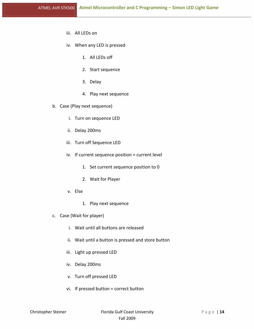
iii. All LEDs on
iv. When any LED is pressed
1. All LEDs off
2. Start sequence
3. Delay
4. Play next sequence
b. Case (Play next sequence)
i. Turn on sequence LED
ii. Delay 200ms
iii. Turn off Sequence LED
iv. If current sequence position = current level
1. Set current sequence position to 0
2. Wait for Player
v. Else
1. Play next sequence
c. Case (Wait for player)
i. Wait until all buttons are released
ii. Wait until a button is pressed and store button
iii. Light up pressed LED
iv. Delay 200ms
v. Turn off pressed LED
vi. If pressed button = correct button

ATMEL AVR STK500 Atmel Microcontroller and C Programming – Simon LED Light Game
Christopher Steiner Florida Gulf Coast University P a g e | 15 Fall 2009
1. Increase level
2. Set sequence position to 0
vii. Else lose game
d. Case (Correct sequence)
i. Play next sequence
e. Case (Lose game)
i. Flash all LEDs twice (200ms delay between flashes)
ii. Setup
f. Case (Win game)
i. Light LEDs from LED0 to LED7 with 500ms delay between walk
ii. Light LEDs from LED7 to LED0 with 500ms delay between walk
iii. Setup
3.2.2 Test Plan
3.2.2.1 Description of Test Environment
The test environment will be the Atmel STK500 circuit board. The microcontroller unit will be
loaded with the Simon LED Light Game C code and will be started to ensure the game starts
properly.
The test environment should exactly simulate the environment in which the software will
ultimately operate.

ATMEL AVR STK500 Atmel Microcontroller and C Programming – Simon LED Light Game
Christopher Steiner Florida Gulf Coast University P a g e | 16 Fall 2009
3.2.2.2 Stopping Criteria
If an error occurs during any test case, the testing phase will continue until the game functions
optimally. The subsequent result of the test will then be recorded and documented accordingly.
The test result documentation will be updated for each iteration of the test phase, per test
case.
If the error occurs during game play, the above will be executed and the game will return to
development phase in order to ensure that the C code operates to design specifications.
The system will be deemed complete when each test phase can be completed with no errors.
Once this happens, the documentation will be updated with the final test results and the
system can then be demonstrated.
3.2.2.3 Description of Individual Test Cases
• Test Case 1
o Test Objective – Ensure that the STK500 turns on properly.
o Test Description – Switch the STK500 power switch to the on position.
o Test Conditions – This test should be completed before any other test cases start
as this is a vital part of the testing phase.
o Expected Results – Once the STK500 is powered on LEDs 0-3 should be lit to
show that the game is ready for use.
• Test Case 2
o Test Objective – Press any switch from SW0 to SW3 to start the game

ATMEL AVR STK500 Atmel Microcontroller and C Programming – Simon LED Light Game
Christopher Steiner Florida Gulf Coast University P a g e | 17 Fall 2009
o Test Description – When any of the switches, SW0 to SW3 are pressed, the game
will enter the Sequence case where a random number is generated to determine
which LED is lit first.
o Test Conditions – This test case should be executed for each switch to ensure
that no matter which switch is pressed, the game will start.
o Expected Results – Once any of the switches are pressed, the first generated LED
will flash.
• Test Case 3
o Test Objective – Press incorrect switch
o Test Description – Tester will press any switch from SW0 to SW3 that is not the
correct switch.
o Test Conditions – This test is to determine that when a player presses the
switches in the wrong sequence that the game will end in a loss.
o Expected Results – Once the tester presses an incorrect switch, all LEDs 0-3 will
light up, turn off and then light up again. This signifies that the game has been
lost and when any switch is pressed the game will restart.
• Test Case 4
o Test Objective – Press correct switch
o Test Description – Tester will press the correct switch that was displayed by the
LED.
o Test Conditions – This test is to determine that when a player presses the correct
switch that the game iterates to the next level.

ATMEL AVR STK500 Atmel Microcontroller and C Programming – Simon LED Light Game
Christopher Steiner Florida Gulf Coast University P a g e | 18 Fall 2009
o Expected Results – When the tester presses the correct switch, the LED should
light up and stay lit for two hundred milliseconds then the LED should turn off
and the LED sequence should restart with the new LED that has been calculated.
• Test Case 5
o Test Objective – Game completion
o Test Description – Tester will press all switches in correct order to win the game.
o Test Conditions – This test is to determine that when the player wins the game
that the winning sequence is completed and the game can be restarted.
o Expected Results – Once the game is won, the LEDs should “walk” from LED0 to
LED7, then in reverse from LED7 to LED0. After this “walk” all eight LEDs should
be lit and the player can press any switch in order to restart the game.
3.3 Current Solution Results
Currently, the code has been written for all levels of the Simon LED Light Game. This is the final
step in the creation of the software as this shows initial start, loss, win and win sequences. The
game can be played successfully as designed. See 4.1 Test Results for each result of testing.

ATMEL AVR STK500 Atmel Microcontroller and C Programming – Simon LED Light Game
Christopher Steiner Florida Gulf Coast University P a g e | 19 Fall 2009
4. Implementation
4.1 Test Results
4.1.1 Test Case 1 Results
• Test Objective – Ensure that the STK500 turns on properly.
• Test Description – Switch the STK500 power switch to the on position.
• Test Conditions – This test should be completed before any other test cases start as this is a
vital part of the testing phase.
• Expected Results – Once the STK500 is powered on LEDs 0-3 should be lit to show that the
game is ready for use.
• Actual Results – The STK500 powered on fine with no issues. The LEDs 0-3 lit up correctly
and the game was ready to start.
4.1.2 Test Case 2 Results
• Test Objective – Press any switch from SW0 to SW3 to start the game
• Test Description – When any of the switches, SW0 to SW7 are pressed, the game will enter
the Sequence case where a random number is generated to determine which LED is lit first.
• Test Conditions – This test case should be executed for each switch to ensure that no
matter which switch is pressed, the game will start.
• Expected Results – Once any of the switches from SW0 to SW3 are pressed, the first
generated LED will flash.
• Actual Results – Pressing the SW0 caused the first LED to light. Pressing the SW1 caused the
first LED to light. Pressing SW2 caused the first LED to light. Pressing the SW3 caused the
first LED to light.

ATMEL AVR STK500 Atmel Microcontroller and C Programming – Simon LED Light Game
Christopher Steiner Florida Gulf Coast University P a g e | 20 Fall 2009
4.1.3 Test Case 3 Results
• Test Objective – Press incorrect switch
• Test Description – Tester will press any switch from SW0 to SW3 that is not the correct
switch.
• Test Conditions – This test is to determine that when a player presses the switches in the
wrong sequence that the game will end in a loss.
• Expected Results – Once the tester presses an incorrect switch, all LEDs 0-3 will light up,
turn off and then light up again. This signifies that the game has been lost and when any
switch is pressed the game will restart.
• Actual Results – Pressing the incorrect switch caused the LEDs 0-3 to light up, turn off and
then light up again, the game successfully accomplished this and restarted. This is the same
for each ten levels of the game.
4.1.4 Test Case 4 Results
• Test Objective – Press correct switch
• Test Description – Tester will press the correct switch that was displayed by the LED.
• Test Conditions – This test is to determine that when a player presses the correct switch
that the game iterates to the next level.
• Expected Results – When the tester presses the correct switch, the LED should light up and
stay lit for two hundred milliseconds then the LED should turn off and the LED sequence
should restart with the new LED that has been calculated.
• Actual Results – When the correct switch was pressed, the next iteration of the LED
sequence was shown correctly. This was true for all ten levels of the game.
ATMEL AVR STK500 Atmel Microcontroller and C Programming – Simon LED Light Game
Christopher Steiner Florida Gulf Coast University P a g e | 21 Fall 2009
4.1.5 Test Case 5 Results
• Test Objective – Game completion
• Test Description – Tester will press all switches in correct order to win the game.
• Test Conditions – This test is to determine that when the player wins the game that the
winning sequence is completed and the game can be restarted.
• Expected Results – Once the game is won, the LEDs should “walk” from LED0 to LED7, then
in reverse from LED7 to LED0. After this “walk” all eight LEDs should be lit and the player
can press any switch in order to restart the game.
• Actual Results – When the game is won, the LEDs successfully walked from LED0 to LED7
and then in reverse from LED7 to LED0. This has been tested multiple times with the same
result.
4.2 Operation and Performance
Each iteration of testing that was completed showed correct results. The microcontroller board
works as designed each and every time of use. Through each level, a correct and incorrect
button was pushed to make sure that this game would work each time it was played. Failure of
the level or completion resulted in correct output to the user. Winning the game also works as
designed.
4.3 Source Code
// INCLUDES #include <avr/io.h> #include <util/delay.h> // PORT/PIN DEFINES #define LEDport PORTC #define LEDddr DDRC

ATMEL AVR STK500 Atmel Microcontroller and C Programming – Simon LED Light Game
Christopher Steiner Florida Gulf Coast University P a g e | 22 Fall 2009
#define BUTTONport PORTA #define BUTTONpin PINA #define BUTTONddr DDRA #define TIMERport PORTD /* Cannot change this, timer 1 is connected to PORTD.5 */ #define TIMERddr DDRD // CONSTANT DEFINES #define OUTPUTS 0xFF #define INPUTS 0x00 #define PULLUPS 0xFF #define BUFFERLEN 10 /*(Ten Levels)*/ // STATE DEFINES #define STATE_Setup 0 #define STATE_PlayNextSeq 1 #define STATE_WaitForPlayer 2 #define STATE_CorrectSeq 3 #define STATE_LoseGame 4 #define STATE_WinGame 5 // MACROS #define GetButton() (uint8_t)(~BUTTONpin & 0x0F) #define Timer1On() TCCR1B |= _BV(CS10) #define Timer1Off() TCCR1B &= ~(_BV(CS10)); PORTD &= ~_BV(5) #define Timer0On() TCCR0 |= _BV(CS00); // PROTOTYPES uint8_t CreateTimerRand(void); void Delay10MS(uint8_t Num); // PROGRAM ROUTINES int main(void) { uint8_t CurrentState = STATE_Setup; uint8_t SequenceBuffer[BUFFERLEN] = {}; uint8_t CurrSeqPosC = 0; uint8_t CurrentLevel = 0; int FlashCount; unsigned char led; //setup led for walk int WalkCount; //initialize WalkCount LEDddr = OUTPUTS; // LED port set as outputs BUTTONddr = INPUTS; // BUTTON port set as inputs LEDport = 0xFF; // All LEDs off initially BUTTONport = PULLUPS; // Enable pullups on the BUTTON port TCCR1A = _BV(COM1A0); // Toggle timer1 output on match TCCR1B = _BV(WGM12); // Clear timer on compare mode Timer0On(); // Turn on the timer 0 while (1) // Infinite Loop { switch (CurrentState) { case STATE_Setup:

ATMEL AVR STK500 Atmel Microcontroller and C Programming – Simon LED Light Game
Christopher Steiner Florida Gulf Coast University P a g e | 23 Fall 2009
CurrentLevel = 1; // Reset current level variable CurrSeqPosC = 0; // Reset current sequence position variable LEDport = 0xF0; // All LEDs on while (!(GetButton())) {} // Wait until a button is pressed, store pressed button LEDport = 0xFF; // All LEDs off SequenceBuffer[0] = CreateTimerRand();
// Create a random sequence byte from the timer value for the first sequence Delay10MS(40); // Wait a 400ms before continuing CurrentState = STATE_PlayNextSeq; break; case STATE_PlayNextSeq: LEDport &= (0xF0 | ~SequenceBuffer[CurrSeqPosC]); // Turn on sequence LED Delay10MS(20); // Wait 200ms LEDport |= (SequenceBuffer[CurrSeqPosC] | 0xF0); // Turn off sequence LED Delay10MS(20); // Wait 200ms if (++CurrSeqPosC == CurrentLevel)
// Sequence playing complete, wait for player input { CurrSeqPosC = 0;
// Reset sequence position counter to 0 CurrentState = STATE_WaitForPlayer; } else // Sequence still playing { CurrentState = STATE_PlayNextSeq; } break; case STATE_WaitForPlayer: while (GetButton()) {};
// Wait until all buttons released before accepting key uint8_t PressedButton = 0; while (!(PressedButton))
// Wait until a button is pressed, store pressed button PressedButton = GetButton(); LEDport &= (~PressedButton | 0xF0);
// Light up the pressed button's LED Delay10MS(20); // Wait 200ms LEDport |= (PressedButton | 0xF0);
// Turn off the pressed button's LED Delay10MS(20); // Wait 200ms

ATMEL AVR STK500 Atmel Microcontroller and C Programming – Simon LED Light Game
Christopher Steiner Florida Gulf Coast University P a g e | 24 Fall 2009
if (PressedButton == SequenceBuffer[CurrSeqPosC]) // Correct button pressed { if (++CurrSeqPosC == CurrentLevel)
// Sequence finished by player { CurrentLevel++;
// Increase the level by one CurrSeqPosC = 0;
// Reset sequence position counter to 0 if (CurrentLevel > BUFFERLEN)
//The entire sequence has been completed { CurrentLevel = 0; CurrSeqPosC = 0; CurrentState = STATE_WinGame; } else
// Still more room in the buffer, create a new random byte and set the //state accordingly
{ SequenceBuffer[CurrentLevel - 1] = CreateTimerRand();
// Create the next sequence byte from the timer CurrentState = STATE_CorrectSeq; } } else { CurrentState = STATE_WaitForPlayer; } } else { CurrentLevel = 0; CurrSeqPosC = 0; CurrentState = STATE_LoseGame; } break; case STATE_CorrectSeq: CurrentState = STATE_PlayNextSeq; break; case STATE_LoseGame: for (FlashCount=0; FlashCount<2; FlashCount++) // Flash the LEDs two times { LEDport = 0xF0; // Turn on all the LEDs Delay10MS(20); // Wait 200ms LEDport = 0xFF; // Turn off all the LEDs
ATMEL AVR STK500 Atmel Microcontroller and C Programming – Simon LED Light Game
Christopher Steiner Florida Gulf Coast University P a g e | 25 Fall 2009
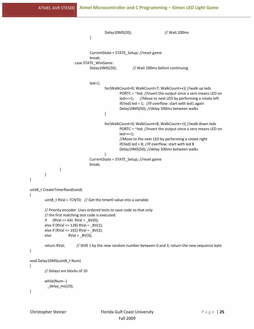
Delay10MS(20); // Wait 200ms } CurrentState = STATE_Setup; //reset game break; case STATE_WinGame: Delay10MS(20); // Wait 200ms before continuing led=1; for(WalkCount=0; WalkCount<7; WalkCount++){ //walk up leds PORTC = ~led; //Invert the output since a zero means LED on led<<=1; //Move to next LED by performing a rotate left if(!led) led = 1; //If overflow: start with led1 again Delay10MS(50); //delay 500ms between walks } for(WalkCount=0; WalkCount<8; WalkCount++){ //walk down leds PORTC = ~led; //Invert the output since a zero means LED on led>>=1;
//Move to the next LED by performing a rotate right if(!led) led = 8; //If overflow: start with led 8 Delay10MS(50); //delay 500ms between walks } CurrentState = STATE_Setup; //reset game break; } } } uint8_t CreateTimerRand(void) { uint8_t RVal = TCNT0; // Get the timer0 value into a variable // Priority encoder: Uses ordered tests to save code so that only // the first matching test code is executed. if (RVal <= 64) RVal = _BV(0); else if (RVal <= 128) RVal = _BV(1); else if (RVal <= 192) RVal = _BV(2); else RVal = _BV(3); return RVal; // Shift 1 by the new random number between 0 and 3, return the new sequence byte } void Delay10MS(uint8_t Num) { // Delays are blocks of 10 while(Num--) _delay_ms(10); }

ATMEL AVR STK500 Atmel Microcontroller and C Programming – Simon LED Light Game
Christopher Steiner Florida Gulf Coast University P a g e | 26 Fall 2009
5. Conclusion
The Atmel STK500 microcontroller board was programmed with the C code that allowed the
board to be used as a Simon Light Game. The user of the board will be able to play the game
and each of its ten levels. Using AVR Studio the code was written and then loaded onto the
board.
Since I have never done any embedded systems programming this project was a first for me. I
spent a lot of time online researching the best way to implement my idea for this project and it
took me many hours to get the required knowledge to just start this project. I learned quite a
bit throughout this project and had a lot of tough times getting the implementation of the code
to the board to work. Once I got the board working, the rest was easy. I was able to load my C
code directly onto the board and see firsthand the joining of C code and hardware.
This individual technology has no real world impact as this has been done before, but I have
seen the power of embedded systems and understand its purpose in our world today.
I would want to take this project to another level and use different colored LEDs and attach a
speaker that will play different sounds for different lights, creating a true Simon LED game.
However I did see some projects that have been done with floor lights to create a dance floor
and the possibility of a standing Simon LED board game would be an ideal project.

ATMEL AVR STK500 Atmel Microcontroller and C Programming – Simon LED Light Game
Christopher Steiner Florida Gulf Coast University P a g e | 27 Fall 2009
6. References
[1] Atmel Corporation, ATMEL STK500 User Guide, Atmel Corporation, September 9, 2009, http://www.atmel.com/dyn/resources/prod_documents/doc1925.pdf
[2] Arild Rødland, Novice’s Guide to AVR Development, AVRFreaks, September 16, 2009, http://www.atmel.com/dyn/resources/prod_documents/novice.pdf
[3] Atmel Corporation, AVR Instruction Set, Atmel Corporation, October 15, 2009, http://www.atmel.com/dyn/resources/prod_documents/doc0856.pdf