ATM virtual private network design...
8
ATM virtual private network design alternatives P Crocetti*, S Fotedart, L Frattat, G Gallassi* and M Gerlaj An ATM virtual private network (AVPN) offers to a multi- site customer an ATM transport service based on a ‘virtual’ topology of dedicated VPs embedded in a larger ATM backbone. The goal of AVPN is to allow the efficient and flexible use of the resources by giving to the customer considerable autonomy in managing such resources. In this paper, we show how this goal can be achieved by exploiting standard ATM features. We also show that a critical issue in AVPN design is congestion control within an AVPN and prevention of interference across different AVPNs. We propose various design alternatives for AVPNs, evaluate their performance and compare their congestion control and dynamic bandwidth allocation features. Keywords: virtual private networks, ATM, congestion control ATM technology makes it easy to ‘embed’ a virtual private network (VPN) in an ATM network (AVPN). The key enabling mechanism is the virtual path (VP) concept, a standard feature which permits establishment of a virtual connection with associated bandwidth between any two points. In the end-to-end application, the user can multiplex several virtual circuits (VC) within the VP, and can thus regard it as a privately owned facility. A multi-site user, by establishing several VPs between all of its sites, can construct a VPN. Recently, this concept of VPN has been extended’ by proposing an embedded network which consists of provisioned VP links maintained between user sites and ATM nodes, as well as between pairs of ATM nodes. In addition, the proposed network supports a logical meshed interconnection between user sites realized using VCs. Different to the end-to-end VP case, the ATM nodes must switch not only the VPs, but also the VCs within each VP. Clearly, this additional flexibility offers several advantages to the user in terms of dynamic utilization of bandwidth, but still leaves some *Italtel, Milan, Italy ‘Politecnico di Milano, Italy tComputer Science Department. UCLA, 37328 Boelter Hall, Los Angeles, CA 90024, USA (Email: [email protected]) problems open, such as contentions resolution for ATM resources. It is expected that the concept of VPNs built on top of ATM will be very attractive, especially in the early stages of ATM introduction. This is because AVPN can be used very effectively as a backbone to interconnect the geographically spread sites of a large customer. Consider, for example, a customer with several LANs (e.g. ATM LANs) which need to be interconnected. One solution is to use the standard, public ATM network service. This, however, may not provide the desired flexibility and control over network resources, Another solution is to build and operate a privately owned nationwide ATM network. However, this involves a major cost investment, and poses technology risks as well as limitations (e.g. lack of growth flexibility). Yet another approach is SMDSjCBDS on top of ATM233. It must be pointed out, however, that SMDSjCBDS has some limitations of its own, as it only supports connectionless data traffic, while future LANs will be increasingly moving towards integrated, multimedia type traffic. It appears that AVPN is an attractive compro- mise among the above approaches, in that it combines their advantages without suffering from many of the limitations. Of course, there is less statistical multiplexing flexibility than in SMDS/CBDS. Also, the user is billed for VP bandwidth, even when he does not use it. It is then the user’s responsibility to ensure efficient use of the bandwidth. Clearly, the customer must take on a more active role in managing network resources. In summary, the objective of AVPN is to offer to a multi-site customer a transport service, based on an ATM backbone, allowing an efficient and flexible use of resources in a changing traffic environment. This is achieved by exploiting the virtual levels typical of the ATM, and by delegating the AVPN traffic management to the user, and yet enabling the public network to guarantee the QoS through proper traffic control functionalities. The main focus of this paper is the analysis of alternative strategies for AVPN, their functional impli- cations and related performance. First, we identify the alternatives for AVPN implementation. For each alter- 24 0140-3664/95/$09.50 6:~ 1995-Elsevier Science B.V. All rights reserved SSD/O140-3664 (94)00748-g computer communications volume 18 number 1 january 1995
Transcript of ATM virtual private network design...
ATM virtual private network design alternatives P Crocetti*, S Fotedart, L Frattat, G Gallassi* and M Gerlaj
An ATM virtual private network (AVPN) offers to a multi- site customer an ATM transport service based on a ‘virtual’ topology of dedicated VPs embedded in a larger ATM
backbone. The goal of AVPN is to allow the efficient and flexible use of the resources by giving to the customer considerable autonomy in managing such resources. In this paper, we show how this goal can be achieved by exploiting standard ATM features. We also show that a critical issue in AVPN design is congestion control within an AVPN and
prevention of interference across different AVPNs. We propose various design alternatives for AVPNs, evaluate their
performance and compare their congestion control and dynamic bandwidth allocation features.
Keywords: virtual private networks, ATM, congestion control
ATM technology makes it easy to ‘embed’ a virtual
private network (VPN) in an ATM network (AVPN). The key enabling mechanism is the virtual path (VP)
concept, a standard feature which permits establishment of a virtual connection with associated bandwidth
between any two points. In the end-to-end application, the user can multiplex several virtual circuits (VC)
within the VP, and can thus regard it as a privately owned facility. A multi-site user, by establishing several
VPs between all of its sites, can construct a VPN. Recently, this concept of VPN has been extended’ by proposing an embedded network which consists of provisioned VP links maintained between user sites and ATM nodes, as well as between pairs of ATM nodes. In
addition, the proposed network supports a logical
meshed interconnection between user sites realized using VCs. Different to the end-to-end VP case, the
ATM nodes must switch not only the VPs, but also the VCs within each VP. Clearly, this additional flexibility offers several advantages to the user in terms of dynamic utilization of bandwidth, but still leaves some
*Italtel, Milan, Italy ‘Politecnico di Milano, Italy tComputer Science Department. UCLA, 37328 Boelter Hall, Los Angeles, CA 90024, USA (Email: [email protected])
problems open, such as contentions resolution for ATM
resources. It is expected that the concept of VPNs built on top of
ATM will be very attractive, especially in the early stages of ATM introduction. This is because AVPN can be used very effectively as a backbone to interconnect the
geographically spread sites of a large customer. Consider, for example, a customer with several LANs
(e.g. ATM LANs) which need to be interconnected. One solution is to use the standard, public ATM network
service. This, however, may not provide the desired
flexibility and control over network resources, Another
solution is to build and operate a privately owned nationwide ATM network. However, this involves a
major cost investment, and poses technology risks as well as limitations (e.g. lack of growth flexibility). Yet
another approach is SMDSjCBDS on top of ATM233. It must be pointed out, however, that SMDSjCBDS has
some limitations of its own, as it only supports connectionless data traffic, while future LANs will be increasingly moving towards integrated, multimedia type
traffic. It appears that AVPN is an attractive compro- mise among the above approaches, in that it combines
their advantages without suffering from many of the
limitations. Of course, there is less statistical multiplexing flexibility than in SMDS/CBDS. Also, the user is billed
for VP bandwidth, even when he does not use it. It is then the user’s responsibility to ensure efficient use of the bandwidth. Clearly, the customer must take on a more active role in managing network resources. In summary,
the objective of AVPN is to offer to a multi-site customer a transport service, based on an ATM backbone,
allowing an efficient and flexible use of resources in a changing traffic environment. This is achieved by
exploiting the virtual levels typical of the ATM, and by delegating the AVPN traffic management to the user, and yet enabling the public network to guarantee the QoS through proper traffic control functionalities.
The main focus of this paper is the analysis of alternative strategies for AVPN, their functional impli- cations and related performance. First, we identify the alternatives for AVPN implementation. For each alter-
24
0140-3664/95/$09.50 6:~ 1995-Elsevier Science B.V. All rights reserved
SSD/O140-3664 (94)00748-g
computer communications volume 18 number 1 january 1995
ATM VPN design alternatives: P Crocetti et al.
native, we describe the functionalities, examine the
critical bandwidth allocation and traffic control
aspects, and evaluate the impact of the protocol
implementations on the ATM node. We then compare the alternatives, both qualitatively and using simple
numerical examples. Finally, we address possible exten- sions to the proposed architectures.
ATM VIRTUAL PRIVATE NETWORK ALTERNATIVES
The simplest solution for an ATM-based VPN is to use
end-to-end VPs (EEVP). A user with a number of sites will interconnect them with a fully interconnected VP
mesh. The ATM network allocates peak bandwidth to VPs and performs peak bandwidth policing on each VP
accordingly. The user can multiplex several VCs within each VP. A major advantage of this scheme is that the user has full control of the VP bandwidth: he can
statistically multiplex several sessions as needed in a way
which is totally transparent to the ATM network. A serious drawback of the EEVP strategy, however, is
bandwidth fragmentation over many VPs, especially with
a large number of sites. The side-effects of fragmentation are the inability to enjoy statistical multiplexing advan-
tages of traffic across VP pipes, and the lack of flexibility
in adjusting to traffic pattern changes. These problems can be solved efficiently by using the
strategy recently proposed by Walters and Ahmed’ under the name of broadband virtual private network (BVPN). The BVPN is a virtual subnet embedded in ATM, which consists of VP links connecting user sites
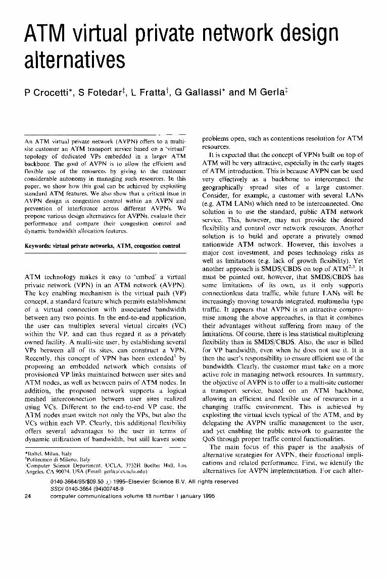
and ATM nodes (Figz4re I). As in the EEVP strategy,
the user is allocated peak bandwidth on the VPS. However, a logical mesh of VCs is defined, where the
VCs are not confined to a single end-to-end VP, but may traverse several VPs. During the data transfer
phase, a temporary association of bandwidth to the VCs of the logical network is realized. Thus, in this case, the network provides not only VP cross-connection, but
also VC cross-connection. The BVPN solution offers considerable advantages to users: first, each traffic
stream, between different source/destination sites, can statistically share a common VP when their paths
overlap; second, traffic pattern changes can be more easily absorbed by a well designed VP topology, without requiring dynamic reallocation of bandwidth, as in the
EEVP strategy.
In this approach, the ATM node must perform some
extra work: first, the ATM node, an ATM Cross Connect (XC) for instance, must now cross-connect not only VPs but also VCs. So, VC routing maps must
be maintained. Another important concern is VP traffic
policing, which is required at each VP segment. Furthermore, VP policing cannot protect the ATM XC from internal congestion caused by changes in traffic patterns. For instance, consider the ATM XC ‘A’ in Figure 1. Assume that initially the traffic into and out of node A is balanced, and therefore bandwidth allocation
Figure I BVPN concept
is the same value for VPs 1, 2, 3 and 4. Accordingly, the
input VP policing parameters are set to the same peak value. Because of traffic fluctuations, it is possible that
during a period, all traffic entering from VPs 1 and 2 goes out to VP 4. Clearly, this overload will cause
congestion in VP 4. Yet ‘output’ policing on VP 4
cannot protect the node from congestion (i.e. internal
buffers may overflow, thus degrading QoS guaranteed to other ATM users). Thus, more elaborate traffic control policies are required.
The problem left open in the BVPN concept, in the definition given by Walters and Ahmed’, is the conten- tion resolution caused by changes in the traffic flows.
Two kinds of approach can be used to solve the problem: either to define a reservation procedure for
traffic acceptance and bandwidth allocation; or to set some limits on resource utilization and flexibility.
Finally, two strategies which follow the above-
mentioned approaches are presented: fast resource management (FRM) and intra-node policing (INP). Before discussing the schemes, it is necessary to
identify the main entities in our network reference scenario (Figure 1). We consider a public network,
which consists of ATM XC nodes, an ATM network manager and a private user who, at each site, has a local
customer manager (LCM) and, optionally, a central customer manager (CCM) to coordinate the LCM operations.
FAST RESOURCE MANAGEMENT FOR AVPN
In the FRM strategy, the user requests peak bandwidth allocation for each incoming burst of traffic or connec- tion. When a burst arrives at the user’s LCM, a fast reservation cell is issued on the proper VC. The first ATM XC on the path verifies that the request can be accepted on the incoming and outgoing VPs (i.e. it keeps track of user bandwidth allocation on VP links).
computer communications volume 18 number 1 january 1995 25

ATM VPN design alternatives: P Crocetti et al
Then, it forwards the fast reservation request to the next node along the path, which in turn verifies that the request can bc accepted on the next VP. In this first phase, 21 bandwidth booking procedure is performed at each node. If the reservation is not blocked, the last
node in the path returns an acknowledgment to the origin, rcscrving bandwidth on the way back and updating the input VC policer in the ingress node. The
sourcc is notified of acceptance, which then issues the burst. Marc detailed examples of protocols can be
found elsewhere4.“.
This scheme clearly protects the ATM XC from congestion, since it polices all the VCs individually, and
thus ensures that the allocated VP bandwidth is never exceeded. It also supports dynamic user bandwidth allocation. The scheme, however, has some drawbacks:
l round trip delay and processing overheads degrade efficiency
0 the procedure is non-transparent to ATM (i.e. the
ATM XC must keep track of user bandwidth allocation)
0 additional hardware and software are required in the ATM XC.
INTRA-NODE POLICING FOR AVPN
Consider F~‘gurc 2, and assume that the input traffic from VP I is split into rates RI3 and RI4 directed to VPs 3 and 4, respectively. Similarly, VP 2 is split into
R23 and R24. The condition to avoid internal node (i.e.
ATM XC) congestion is that RI3 + R23 < peak
bandwidth allocated to VP 3. Ideally. we would like to jointly police the sum RI3 and R23. Unfortunately this is not possible. since these two traffic streams enter from
two different exchange terminations. Policing requires counting cells in real-time, and
therefore it can be performed only on the exchange
termination on which the traffic stream is entering. Therefore. a more realistic solution entails the policing
of RI 3 and R23 separately. This policing strategy, which we call intra-node policing (INP), is quite easy to implement. It simply requires keeping ;I common
policing counter for all the VCs which are routed from
VP I to VP 3. If RI3 and R23 are chosen so that R I3 + R23 < peak bandwidth allocated on VP 3, nodal
congestion is prevented. Thus the scheme is fail-safe.
ATM XC
However, from the user performance standpoint, this scheme is quite conservative, since it does not allow statistical multiplexing of the streams corresponding to RI3 and R23. Conceptually, it is as if artificial
‘Intranode-Virtual Path’ (I-VP) links were introduced
between the original internodal VPs. These I-VPs clearly pose further constraints on user bandwidth allocation,
and may, in some cases, become undesirable bottle-
necks, unless properly chosen.
In a static I-VP assignment, the I-VP policing parameters are selected at the AVPN set up. The
policers on each I-VP enforce the assigned parameters to prevent congestion in the ATM network. To accept a
new session the LCM requests an access permit to its privately owned CCM. The CCM is. therefore, updated
on the actual traffic in the AVPN. and may accept or reject the new session based on peak or statistical
multiplexing criteria applied to the I-VP involved. In this case, the INP operation is completely transparent to
the ATM XC. Unintentional or malicious misfunc-
tioning of LCM or CCM has an impact only within the
AVPN. All other users preserve their guaranteed
performance in the ATM network. A drawback of static I-VP assignment is poor
performance when AVPN traffic patterns change substantially. This may be corrected by allowing the
user to change the I-VP policer parameters. The implementation of such an alternative, however. requires the existence of ATM signalling and the use of
more sophisticated procedures. If these features are available. the CCM periodically readjusts the thresh-
olds so that they are consistent with the traffic pattern.
Each ATM XC, of course. checks the new thresholds for consistency. The fragmentation problem here is mitigated by the fact that the I-VP bandwidth alloca-
tions are matched to the actual user traffic pattern.
FUNCTIONAL COMPARISON
Each of the three AVPN schemes described in the previous section has a different impact in terms of functional requirements for supporting the ATM network. To evaluate and compare their impacts. it is
necessary to define the basic functions needed to run an AVPN. For the sake of clarity. we refer to the following
phases in AVPN operation:
0 network set-up. which includes all actions needed to intialize AVPN
l connection acceptance. which is in charge of all decisions related to the acceptance of incoming connections into the AVPN
l data transfer. which controls the data transfer during connections.
Ttrhk~~ I summarizes for each basic function and for the different schemes the phase at which it is performed and the type of connection and entity involved.
The 7~177tir7!: function. which sets the routing tables in each ATM XC. is always performed during the network
26 computer communications volume 18 number 1 january 1995

I ATM VPN design alternatives: P Crocetti et al.
set-up phase. In the INP and FRM strategies. this function is required for both VP and VC.
The htrrd~~~irlth rrlloctrtim function, which assigns
bandwidth to the ATM VPN on a long-term basis, is
again implemented in the network set-up phase and
affects only the VP. The approach to cmtcntion resohtion in the access to
AVPN resources strongly characterizes the alternatives.
In the case of EEVP. the problem is solved in a
prcvcntive way by the ATM network manager (ATM NM) during the network-set-up phase. In the INP
strategy. the public network is not involved. The CCM handles the contention. On the other hand. in the FRM scheme, the LCM interacts directly with the ATM nodes,
which check the bandwidth availability hop by hop. The p/ich,q pwauwtcv tr.s.sig~~nwnt function sets the
parameters used in the AVPN trafficcontrol. In the EEVP
these parameters simply correspond to the peak bandwidth selected for the VPs. In the INP the policing
parameters limit the peak bandwidth of the I-VP (that is. a bundle of VCs) and must be determined according to
routing and bandwidth allocation functions. In the FRM. the policing parameters limit the VC peak bandwidth and
are updated at each connection set-up and release. The policit~g function enforces the policing para-
meters selected by the previous function. The policer operates on VP. lntranode Virtual Path or VC as specified by each scheme.
The implementation of the bandwidth allocation
schemes involves several network elements: LCM and
CCM, in the private environment: and the ATM
Network manager and ATM XC in the public environ- ment. However. the complexity of the functions
performed by each element varies depending on the strategy used. The EEVP does not require any extra functions from the public network. In fact. the LCM achieves multiplexing only in the single VP connecting two end-to-end users.
In contrast. the involvement of the ATM XC to perform I-VP policing. as requested by the INP
strategy, allows a higher degree of multiplexing. In addition, this policy needs the support of a CCM to regulate access to the AVPN, resulting in an additional overhead in the private domain. which thus largely becomes the responsible AVPN management.
Unconstrained statistical multiplexing in the VPs is obtained in the FRM strategy. at the cost of a higher
involvement from the public network. This includes the introduction of new hardware and software units in the ATM XC to support FRM. In this strntegy, AVPN
access control is regulated by the public network. Note that the last two strategies require an ATM
signalling procedure. In fact. the LCM must be able to
generate control messages to either CCM or ATM XC. From the above considerations. it follows that the
architecture of an ATM XC must have ;I large degree
of flexibility to be able to support the emerging AVPN strategies”-7. The flexibility mainly relates to three
design aspects:
l the overall system architecture. which should be open. for instance, to FRM unit introduction through the use of modular criteria
a the ATM layer functionalities. which should include the options to cross-connect either on a VP or on ;I
VPjVC basis, and should allow ;tlternative strate- gies for traffic control
0 cross-connecting capabilities. which should be intrinsically robust against intro-node traffic
changes.
PERFORMANCE CONSIDERATIONS
To further compare the three strategies. let us first define
the performance criteria. Throughput, as usual. is the main concern. The throughput evaluation. of course. is
influenced by several parameters, such as traffic pattern
characteristics. Another important measure is response time for connectionless traffic. A slow response implies
that bursts must be buffered at the source gateway. It buffering is inadequate, they may be dropped. The impact on implementution is also critical. One must verify feasibility and estimate the ‘cost’ of thcsc imple-
mentations. Another desirable property is the ability to phase in the private network gradually. starting from :I few point-to-point connections.
We now proceed to the comparison of OLII- three alternatives. Starting with the EEVP scheme. we note that this scheme is completely transparent to the ATM network. Furthermore, it permits ;I gmdunl expansion of the private network. even from ;I sin& point-to- point link. with no need for special procedures. Finally, it poses no restrictions on user bandwidth allocation on
computer communications volume 18 number 1 january 1995 27

ATM VPN design alternatives: P Crocetti et al.
end-to-end VPs. However, EEVP cannot handle drastic changes in traffic pattern, and does not allow the statistical multiplexing of streams between different source/destination pairs.
Moving now to the AVPN schemes, we examine the
FRM. On the positive side, we note that FRM can easily accommodate changes in traffic pattern, and it
permits dynamic sharing of VP bandwidth among different source/destination streams. However, it incurs additional implementation costs because of the FRM procedure, which must be implemented in hardware. Furthermore, the round trip delay and ATM XC
internal procedure overhead, because of the need to
reserve bandwidth and set up the policing parameters
for each burst, should be carefully evaluated, and may cause buffer overflow at the source gateway. In an
attempt to reduce the processor and response time overheads caused by the FRM, one could transmit a
sequence of bursts in the same session using the same reservation. But then, performance may suffer, since in
FRM only peak bandwidth can be reserved. However, FRM does not allow a gradual phase-in, starting from a
single point-to-point link. All the fast reservation protocols must be in place from the beginning.
The last scheme we consider is INP. A major
advantage of INP. as compared with FRM, is ATM transparency. In fact, INP does not require the
implementation of special ATM procedures. Conse-
quently, it does not pose much of a burden on the ATM switch. It does. however, require the active
participation of CCM and LCMs in the bandwidth allocation and resource management. That is, the user incurs the cost of a CCM and of LCMs, which keep track of bandwidth usage and carry out peak or
statistical bandwidth allocation decisions. Thus, with respect to the FRM, the implementation cost has now
shifted from the ATM node to the user network management centre. A side benefit of ATM transpar-
ency is the fact that phase-in is now easy, since the
complexity is in the private equipment. From the
performance standpoint, the INP scheme can achieve very good throughput efficiency because of its ability to
statistically multiplex several user streams together. However, one potential bottleneck in INP, which does not exist in FRM, is the fragmentation of I-VP
bandwidth. Namely, if the number of VPs to a single node is large, then many I-VPs must be maintained within the node. These I-VPs limit the user’s ability to take full advantage of the bandwidth available.
Obviously, the INP scheme does not work well in this
case. In the next section, we compare throughput performance of the various alternatives in a simple numerical example.
NUMERICAL EXAMPLES
A quantitative comparison of the bandwidth allocation strategies was carried out for three representative virtual topologies: ring, star and mesh (see Figure 3). The ring
b
c
Figure 3 Three virtual topologies used for performance comparison of FRM, INP and EEVP schemes. (a) Ring topology; (b) star topology; (c) circuits in the second NSFnet backbone 1989-90
and star topologies were chosen because they are easy to
analyse due to symmetry, and thus allow straightfor- ward evaluation of performance sensitivity to several
parameters (e.g. network size). Furthermore, ring and star turn out to be the best and worst cases, respectively,
for the INP scheme. The mesh topology example (inspired by a recent NSFnet backbone’) was chosen as a realistic example of an actual AVPN topology
embedded in a wide area ATM. The mesh is expected to exhibit performance somewhere between that of the ring and star topologies.
Traffic requirements were assumed to be uniform
between all node pairs. More specifically, each node
pair has a session with peak bandwidth Bp, burstiness h and mean burst length L. Burst length and interarrival
time were assumed to be exponentially distributed, with the mean burst length L equal to 100 cells. Quality of
Service (QoS) was defined as the burst loss probability P,,, which for our purposes is more meaningful than the conventional cell loss rate. In our examples, we defined QoS, the burst loss probability P,,, to be less than or equal to 10p4. The performance measure used to
compare the various schemes is the VP bandwidth required on each AVPN link (for the star and ring topologies), or the aggregate bandwidth of all the VPs over the entire network (for the mesh topology).
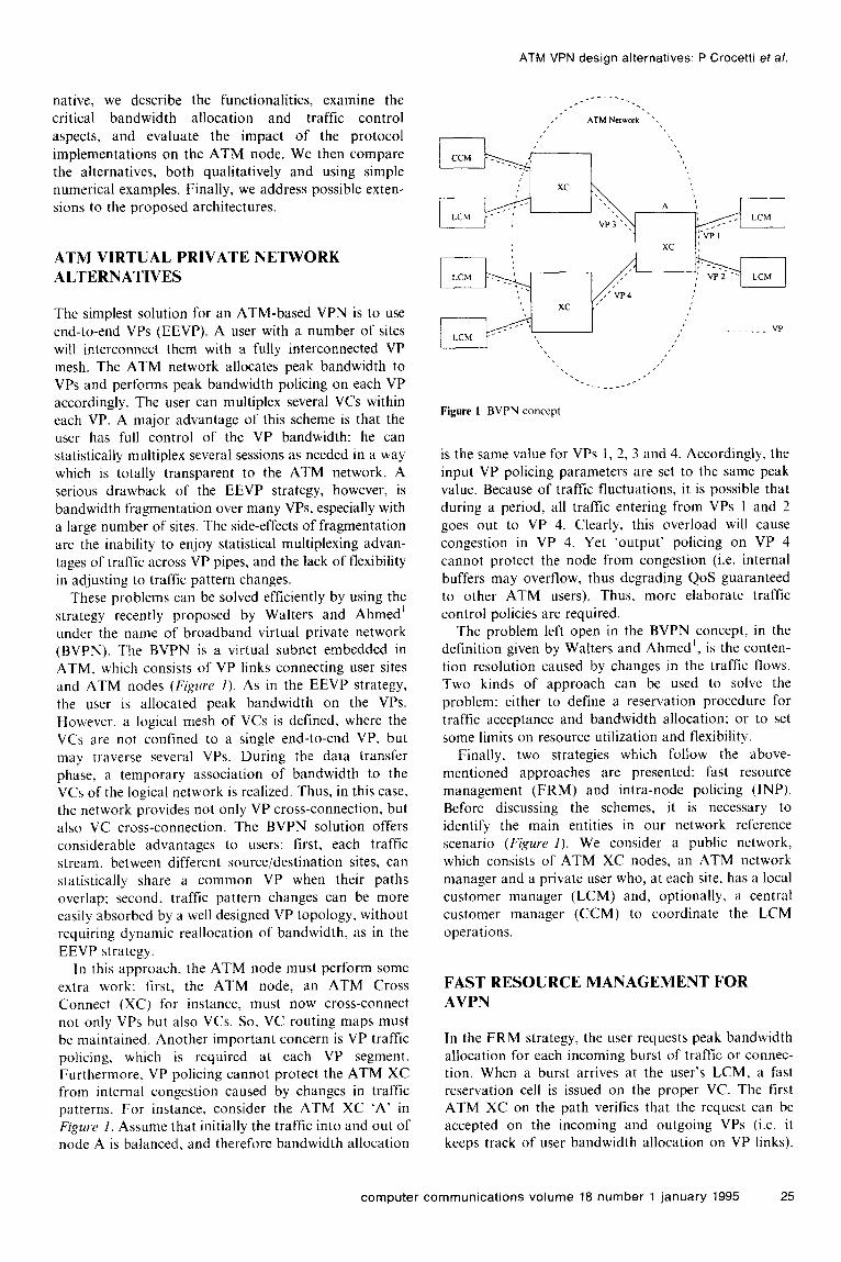
Figure 4 illustrates the VP layout in a node of the ring topology for the EEVP, INP and FRM strategies. Similar layouts exist in the nodes of the star and mesh topologies. As shown in Figure 4a, a separate VP is maintained for each session on each link in the EEVP strategy. In the INP strategy (Figure 46), only one VP is established on each link. This VP carries the sum of two
28 computer communications volume 18 number 1 january 1995
Link INl’ bandwidth
Link
FRM bandwidth
User User User a b C
different streams. namely the transit stream and the
local stream. The two streams. albeit travelling on the
same VP, cannot be statistically multiplexed since they
correspond to two different I-VPs separately controlled
by the policers at the node ingress. In the FRM case
(F&W 4). there is again only one VP per link. In this
case, statistical multiplexing is possible for the entire
traffic flow within the VP.
Performance models
We have developed analytical models to compute the
bandwidth required on each link to achieve the desired
QoS (P,, < IO ‘). For simplicity, no buffering at the
user site was considered. Furthermore, buffering would
introduce delays. which may adversely affect some of
the AVPN applications. In the model. for the EEVP
case. each VP is allocated the full session peak
bandwidth. B,). since it carries only one session. In the
ring topology. assuming shortest path routing, the
number of sessions per link results as:
N \
= ((N- 1)/2f IN- I)/2 ?
while in the star topology, the number of sessions per
link is N, = N - I. where N is the number of nodes in
the system. Thus, the link bandwidth required for the
EEVP scheme = N, x B,,. For the mesh topology, the
link bandwidth for the EEVP case is also computed
analytically assuming shortest path routing. Since link
bandwidth varies from link to link, the sum of all link
bandwidths is used as a measure of performance.
In the FRM strategy, the Engset model is used to
evaluate burst loss due to blocking”. We model a link as
an M-server. pure loss system with finite customer
population equal to the number of sessions present on
the link. The probability of burst loss is thus given by:
P,, =
where x z 5. 2. = burst mean inter-arrival rate; 11
Analytical and simulation results
,H = burst mean duration; S = number of sessions; and Figwxs 5~ 7 show the performance of the three
M = number of servers (channels). bandwidth allocation schemes for the ring topology. In Substituting the value IO 4 for P,,, and the value of N, Fijywc 5, the link bandwidth required to keep the burst
for S, we get M, the number of servers (that is. the loss probability at IO 4 is plotted :!gainst the burstiness
ATM VPN design alternatives: P Crocettl et al.
number of ‘virtual’ channels. each of bandwidth B,,) per
link required to provide the desired QoS. The link
bandwidth is then given by M x B,,. where B,) is the
peak session bandwidth. The overhead due to the initial
negotiation process in the FRM scheme is accounted for
by adding an estimate of the negotiation time to the
burst mean duration. The duration of the negotiation
process was computed by assuming 2 ms constant delay
per hop. This accounts for the transmission. processing
and propagation delay of the reservation packet on each
hop along the path.
For the INP case. ;I worst cast model is used to
determine the burst loss due to temporary I-VP overload.
The customer population is again finite (i.e. number of
sessions = S). but the number of servers (that is. the
number of channels in ;i link) is assumed to be infinite.
since in INP. ;I burst atnnot be blocked or stopped at the
source when it exceeds the reserved bnndwidth. In OLII
conservative model all concurrent bursts are assumed to
be lost whenever the number of bursts exceed ;I pre-
determined threshold. This corresponds to the assump-
tion that whenever the sum of the rates of the incoming
bursts exceeds the rate controlled by the input policer.
the policer drops cells randomly from the incoming
bursts. thus damaging them all. A more sophisticated
policer could selectively drop ceils from only ;I few
bursts. thus improving performance. Unlike the FRM
case (where only peak bandwidth :tllocation is
performed), the CCM in INP c:in use either peak or
statistical multiplexing criteria to accept,‘reject sessions.
In our model, we use the statistical approach. The burst
loss probability in the INP scheme is given as follows”:
where:
S
0 xi,
/J/s = ___ ( I “- rxY
From this model. we derive the bandwidth allocation
which guarantees PI, = IO 4.
In addition to the analysis, we have also used
simulation for the FRM and INP schemes to validate
the Lmalytic results. Each simulation wils repeated
several times to compute the overall burst loss prob-
Lability within a 95% confidence interval using the /-
distribution.
computer communications volume 18 number 1 january 1995 29

ATM VPN design alternatives: P Crocetti et al.
LO”“” 1 1 performs poorly. since it does not allow statistical
IO ’ I 100 1000 10000
Figure 5 Link bandwidth I‘CI’W~ hurstiness in ring topology (B,, ~ IO Mbit,‘s, N = 50). A: FRM (simulation): : FRM
(analysis): 0: INP (simulation): -: INP (analysis): x : EEVP
10000 , ! I / I / I I
1 1 2 3 4 5 6 7 8 9 10
Session Peak Bandwidth (Mbps)
Figure 6 Link bandwidth WI’.~II.Y peak handwidth in ring topology (8 = IWO. A’ ~ 50). (For key see K~,~wc~ 5)
10 1 L I 5 10 15 20 25 30 35 40 45 50 55
Number of node4
Figure 7 Link bandwidth IW.W~ number of nodes in ring topolog (B,, = IO Mhit:s. h = 1000). (For key see Fi,~r~c .S)
of the traffic, which langes between 100 and 10000. Peak session bandwidth is assumed to be IO Mbit/s and the number of nodes in the system is 50. Since the peak
bandwidth and burst length remain constant. increasing the burstiness implies increasing the meun burst inter-
orrivnl time. As a result. the link bnndwidth required in the FRM and INP schemes decreases as the burstincss increases. Since the FRM scheme suffers the overhead of reserving the bnndwidth for 21 burst before it can be transmitted. burst loss tends to be milch higher than for INP. which does not have this overhend. However, as the burstiness incre:lses, the FRM performance
:lpproaches thut of INP. since bursts arrive less frequently and the system has enough time to reserve the bandwidth :lnd transmit the current burst before a new burst arrives. As expected. the EEVP scheme
multiplexing of bandwidth and needs peak bandwidth allocation on all VPs. irrespective of burstiness. For FRM and INP schemes. both analytic and simulation
results are reported in Figurr 5. The simulation values (obtained with 95% confidence intervals) are in good
agreement with the analytic values. thus conlirming the
validity of the analytic models. F@w 6 compares the three bandwidth allocation
schemes as the peak session bandwidth is increased
from I IO Mbit/s. Increasing the session peak
bandwidth decreases the mean burst duration. The behaviour of the FRM and INP schemes is similar to
that observed in Figure 5. When the session peak
bandwidth is low, the burst duration is large enough to mask the FRM negotiation process. allowing it to
perform well compared to the INP scheme. For high peak rates, INP outperforms FRM.
Figw~~ 7 shows the required link bandwidth IYXSII.S the
number of nodes in the system, assuming the session peak bandwidth to be IO Mbit/s and burstiness to be
1000. As the number of nodes increases. the traffic on
each VP increases. Increase in traffic due to the increase
in the number of nodes causes the same problem in the
FRM scheme as that noted in Fig~ws S and 6. Thus, for the chosen set of parameters. FRM tends to perform
better than INP for :I small number of nodes, and worst than INP for a large number of nodes.
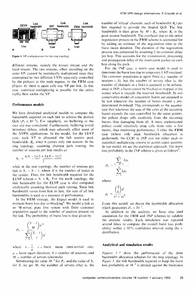
Figwx~.r (Y-10 show the performance of the FRM. INP
and EEVP schemes on a star topology. As expected. the INP scheme performs the same as the EEVP scheme due to the fragmentation at the centre of the star. The FRM scheme performs better than the other two schemes, und its behaviour in the star topology is similar to th:lt
exhibited in the ring topology.
The results obtained with ring and s&r topologies support the notion that the INP scheme is very sensitive
to node connectivity. ;md in particular. performs very poorly when model connectivity is high (such as in the
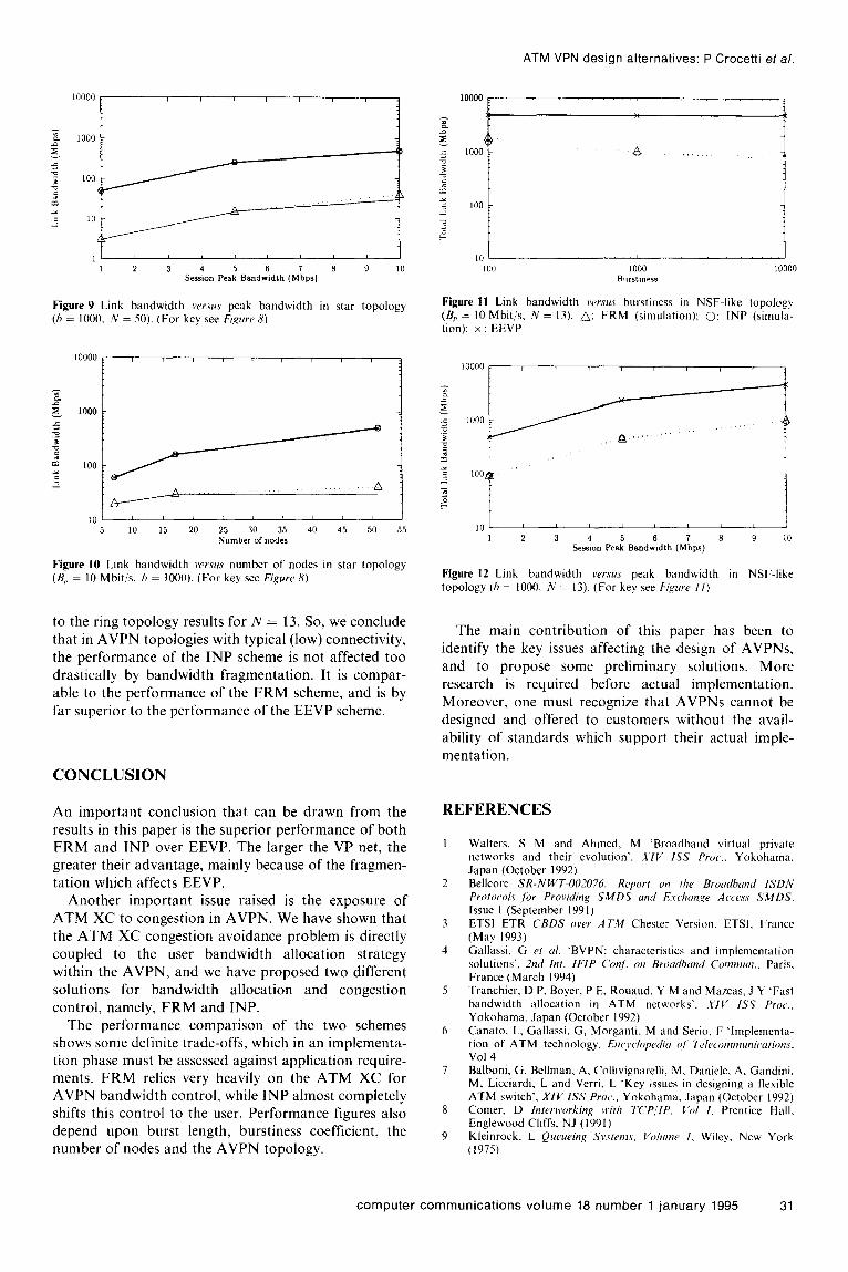
star topology). because of I-VP fragment:ltion. The question is how will INP perform in a ‘typical’ AVPN topology. The experiments based on the NSFnet-like mesh topology shed some light on this issue. In Figwc~.v
11 and I.?. we note that the simulation results for FRM and INP ilre very close to each other. :lnd are very similar
‘“““” [
Figure 8 Link bandwidth WI’.W\ hurstiness in star topology (B,, : IO Mhil c. R: ~ 50). A: FRM (simulation): : FRM (annly4s): 0: INP: x : FEVP
30 computer communications volume 18 number 1 january 1995
ATM VPN design alternatives: P Crocetti et al.
1 ’ I
1 2 3 Se.& 5 Peak
Bandw6idtb 7 8 9 10 (Mbps)
Figure 9 Link bandwidth I~U.I‘U.S peak bandwidth in star topology (h = 1000. iii = 50). (For key see Figure 8)
10 ’ L I
5 10 15 20 25 30 35 40 45 50 55
Number of nodes
Figure IO Link bandwidth versus number of nodes in star topology (B,, = 10 Mbit/s, h = 1000). (For key see Figure 8)
to the ring topology results for N = 13. So, we conclude
that in AVPN topologies with typical (low) connectivity, the performance of the INP scheme is not affected too
drastically by bandwidth fragmentation. It is compar- able to the performance of the FRM scheme, and is by
far superior to the performance of the EEVP scheme.
CONCLUSION
An important conclusion that can be drawn from the results in this paper is the superior performance of both FRM and INP over EEVP. The larger the VP net, the
greater their advantage, mainly because of the fragmen- tation which affects EEVP.
Another important issue raised is the exposure of ATM XC to congestion in AVPN. We have shown that
the ATM XC congestion avoidance problem is directly coupled to the user bandwidth allocation strategy
within the AVPN, and we have proposed two different solutions for bandwidth allocation and congestion
control, namely, FRM and INP. The performance comparison of the two schemes
shows some definite trade-offs, which in an implementa- tion phase must be assessed against application require- ments. FRM relies very heavily on the ATM XC for AVPN bandwidth control, while INP almost completely shifts this control to the user. Performance figures also depend upon burst length, burstiness coefficient. the number of nodes and the AVPN topology.
Ill L I
‘100 1000 10000
Burstmess
Figure 11 Link bandwidth versus burstiness in NSF-like topology (B,, = IO Mbit/s. N = 13). A: FRM (simulation): 0: INP (simula- tion); x : EEVP
, 10 1
I 2 3 Sesion 5 Peak
Bandwidth 7 8 9 IO (Mbps)
Figure 12 Link bandwidth versus peak bandwidth in NSF-like topology (h = 1000. N = 13). (For key see F&tre I I)
The main contribution of this paper has been to identify the key issues affecting the design of AVPNs,
and to propose some preliminary solutions. More research is required before actual implementation.
Moreover, one must recognize that AVPNs cannot be designed and offered to customers without the avail-
ability of standards which support their actual imple- mentation.
REFERENCES
Walters, S M and Ahmed, M ‘Broadband virtual private networks and their evolution’, XIV ISS Prw.. Yokohama, Japan (October 1992) Bellcore SR-N WT-002076: Report on lhe Broudhund ISDN Protcmls for Providing SMDS and l%chun,qe Awe.~s SMDS,
Issue I (September 1991) ETSI ETR CBDS over ATM Chester Version, ETSI. France (May 1993) Gallassi, G PI al. ‘BVPN: characteristics and implementation solutions’. 2nd ht. IFIP Cmf: on Broudbund Cornrnur~.. Paris. France (March 1994) Tranchier, D P, Boyer, P E, Rouaud, Y M and Mazeas, J Y ‘Fast bandwidth allocation in ATM networks’, XII’ ISS Proc.,
Yokohama, Japan (October 1992) Canato. L, Gallassi, G, Morganti. M and Serio, F ‘Implementa- tion of ATM technology. Enc~vc~lopdiu of T~~l~c,or,?munic,cIriorrs, Vol 4 Balboni, G, Bellman, A, Collivignarelli. M. Daniele. A. Gandini. M, Licciardi, L and Verri. L ‘Key issues in designing a flexible ATM switch’, XIV ISS Proc.. Yokohama. Japan (October 1992) Comer. D Inlwwwrking with TCP,!IP. C’ol I, Prentice Hall, Englewood Cliffs, NJ (I 991) Kleinrock. L Quewing S~‘strnw. Vhmc 1. Wiley, New York (1975)
computer communications volume 18 number 1 january 1995 31