ATM Tutorial - · PDF fileRelease 1.2, August 5, 2004 1 FNC Educational Services ATM Tutorial...
30
ATM Tutorial August 5, 2004 ATM
Transcript of ATM Tutorial - · PDF fileRelease 1.2, August 5, 2004 1 FNC Educational Services ATM Tutorial...

ATM Tutorial
ATM
August 5, 2004

Trademarks and Copyrights
Adobe Acrobat and Reader are registered trademarks of Adobe Systems, Inc.
UNIX is a registered trademark of The Open Group
All other products or services mentioned in this dcompanies that market those products or servicedirectly to those companies
This document and its contents are provided by F“as is” with no warranties or representations whamerchantability and fitness for purpose. FNC doe
Furthermore, the contents of this document are swithout notice, to make changes in equipment dethis document may be copied, modified, or otherw
Unpublis Copyrigh
ocument are identified by the trademarks, service s or own those marks. Inquiries concerning such p
ujitsu Network Communications Inc. (FNC) for guitsoever, either express or implied, including withous not warrant or represent that the contents of this
ubject to update and change at any time without nsign or components as progress in engineering mise reproduced without the express written conse
hed work and only distributed under restriction.t © Fujitsu Network Communications Inc. All Rights
marks, or product names as designated by the roducts, services, or marks should be made
dance purposes only. This document is provided t limitation the implied warranties of document are error free.
otice by FNC, since FNC reserves the right, ethods may warrant. No part of the contents of nt of FNC.
Reserved.

Ethernet TutorialFNC Educational Services
Introduction.................................................................................. 1Objectives................................................................................ 1Standards ................................................................................ 1Distribution Method ................................................................. 1
ATM ............................................................................................. 3The ATM Forum, ITU and ANSI .............................................. 3
ATM Cells .................................................................................... 5Header Cell Structure.............................................................. 5
ATM Protocol ............................................................................... 7Physical Layer ......................................................................... 7ATM Layer............................................................................... 7
AAL Type 1 (AAL1) ............................................................. 9AAL Type 2 (AAL2) ............................................................. 9AAL Type 3/4 (AAL3/4) ....................................................... 9AAL Type 5 (AAL5) ............................................................. 9
ATM Service Categories............................................................ 11ATM Access............................................................................... 13
ATM Interface Connections................................................... 13ATM Connections.................................................................. 13ATM Connection Topologies ................................................. 13
Virtual Paths and Virtual Channels ............................................ 15Virtual Path and Channel Switches ....................................... 15
ATM Quality of Service.............................................................. 17ATM Traffic Contract ............................................................. 17
ATM Traffic Control.................................................................... 19Connection Admission Control .............................................. 19Parameter Controls ............................................................... 19Priority Control....................................................................... 19Network Resource Management........................................... 19Traffic Shaping ...................................................................... 19
ATM Advantages ....................................................................... 21ATM Disadvantages .............................................................. 21
ATM Acronyms .......................................................................... 22Tutorial Review.......................................................................... 23
Answers .....................................................................................25
Release 1.2, August 5, 2004 iFNC and FNC Customer Use Only

FNC Educational ServicesEthernet Tutorial
ii Release 1.2, August 5, 2004FNC and FNC Customer Use Only

ATM TutorialFNC Educational Services
IntroductionThis self-study tutorial satisfies the prerequisite for Asynchronous Transfer Mode (ATM) that is required for attendance at Fujitsu Network Communications Inc. (FNC) Educational Services training classes.
ObjectivesAfter completing this lesson, the student should be able to describe ATM cells, discuss ATM protocol and transmission (including ATM service classes, categories, and quality), and define ATM terminology.
StandardsThe student should complete the tutorial and take the Self Evaluation at the end of the tutorial. If the student passes the evaluation by missing no more than three questions, the ATM prerequisite is satisfied. If more than three questions are answered incorrectly, the student should review the tutorial again and make sure the information relating to the missed questions is understood. Each student should be familiar with concepts and terms of the tutorial prior to attending class.
Distribution MethodThe ATM tutorial is available at the following Internet address:
http://us.fujitsu.com/img_assets/FNC/pdfServices/atm-guide.pdf
The tutorial can be viewed using Adobe® Acrobat® Reader®.
Release 1.2, August 5, 2004 1FNC and FNC Customer Use Only

FNC Educational ServicesATM Tutorial
Figure 1: ATM Network
Private ATM
Switch
ATMUser
ATMUser
ATMUser
Public ATM
Network
Private UNI
Public UNI
Private ATM
Switch
ATMUserATMUser
ATMUserATMUser
ATMUserATMUser
Public ATM
Network
Private UNI
Public UNI
2 Release 1.2, August 5, 2004FNC and FNC Customer Use Only

ATM TutorialFNC Educational Services
ATMAsynchronous Transfer Mode (ATM) is a switching and multiplexing technology that employs small, fixed-length cells to very quickly and efficiently move all types of traffic. ATM is fast and efficient because its cells fit into spaces too small for larger packets or frames, traffic routes are preplanned, switching is done without the need for time-consuming software, and payload error checking and correction is performed only at the destination node, not at every hop along the way.
ATM was designed to be the protocol of choice for future Broadband-Integrated Services Digital Network (B-ISDN) services. Because ATM is asynchronous, it provides true bandwidth-on-demand. Additionally, its small cell size makes ATM adaptable to any form of information—data, voice, video, audio, e-mail, faxes—and capable of moving this information amazingly fast across a network that can provide millions of virtual paths and channels between end user equipment.
Characteristically, ATM has two dimensions: transport and switching. In the transport dimension, ATM can move no faster or slower than any other digital communication technology. It is in the switching dimension that ATM shines. Packets and frames of various sizes need smart switches controlled by slow-moving software to move them through a network. Small, uniformly sized cells on an ATM network move through switches without needing software assistance. The cells already know the route to take and do not need to slow down to look for road signs or stop to get directions.
ATM allows the user to select the level of service it needs, provides guaranteed service quality, and makes reservations and preplans routes so those signals needing the most attention are given the best service. Whether the signal travels first class or standby, ATM can accommodate the user.
The ATM Forum, ITU and ANSIThe ATM Forum was started in 1991 by four computer and telecom vendors. Today nearly 1000 members of the ATM Forum work for equipment and service providers, manufacturers, carriers, and end users interested in accelerating the definition, development, and deployment of ATM technology. While the forum is not a standards body, the International Telecommunication Union (ITU), the most important telecommunications standards body in the world, considers the ATM Forum a very credible working group.
The ITU is rooted in the International Telegraphy Union, founded in Paris in 1865. Its name changed in 1934, and in 1947 the ITU became an agency of the United Nations. The ITU works with public and private organizations to develop earth-linked and satellite communications, while developing standards for all types of telecommunication technology.
The ITU-Telecommunication Standardization Sector (ITU-T) is the leader in defining Integrated Services Digital Network (ISDN), B-ISDN, and ATM specifications. The American National Standards Institute (ANSI) is the formal standards body guiding the development of ATM in the US.
Besides the ATM Forum, Telecom and the Internet Engineering Task Force (IETF) are interested in ATM standards. Telecom focuses on network products and services affecting local exchange service, and IETF is concerned with how ATM is used with the Internet
Release 1.2, August 5, 2004 3FNC and FNC Customer Use Only

FNC Educational ServicesATM Tutorial
Figure 2: ATM Cells
UNI Cell NNI Cell
4 Release 1.2, August 5, 2004FNC and FNC Customer Use Only

ATM TutorialFNC Educational Services
ATM CellsAn ATM cell is a 53-octet packet of information consisting of two main parts (see Figure 2):
• Header—5 octets reserved for:
- Routing (GFC)
- Addressing (VPI, VCI, PTI)
- Flow control (CLP, HEC)
• Payload—48 octets reserved for voice, video, audio, and data (user or service)
The cell size is a compromise between what Europe and the United States wanted. Europe liked a 32-octet payload to reduce delay (smaller cells get through switches more quickly). The US preferred a 64-octet payload to increase bandwidth efficiency (because of a better header-to-payload ratio). The ITU settled the issue with a 48-octet compromise, giving both sides a portion of what they wanted. After adding five header octets, the ATM cell size is 53 octets (this gives an approximate 1:10 ratio between header and payload cells).
Header Cell StructureThere are 40 bits in each ATM header. These bits are subdivided into various-sized groupings designed to move payload through the ATM network to its destination. These subgroups are:
• Generic Flow Control (GFC)—Four bits that control traffic flow between the ATM network and terminal equipment. These are gatekeeper bits that do not travel with the cells across the ATM network but are used to establish connections with end user equipment.
Additionally, GFC bits:
- Manage access conflicts, giving each user fair access to the ATM network
- Ensure that proper quality of service is allotted to each user (see ATM Traffic Contract on page 19)
- Support up to 100 users on each UNI
• Virtual Path Identifier (VPI)—The address for up to 256 UNI virtual paths (VPs) (8 VPI bits) or up to 4096 NNI VPs (12 VPI bits). The path is fixed at connection but is shared with multiple other calls. Because NNI VPIs overwrite UNI GFC bits, more than 4000 virtual paths can be used within the ATM network.
• Virtual Channel Identifier (VCI)—The rest of the VPI address that identifies virtual channels within each virtual path. Sixteen bits make possible 65,536 virtual channels. The combination of VPI and VCI fields allow for 16,777,216 simultaneous UNI calls and up to 268,435,456 simultaneous NNI calls.
• Payload Type Identifier (PTI)—Three bits that identify the cell as carrying information for the user or as carrying service information.
• Cell Loss Priority (CLP)—One bit that determines if a cell can be discarded if the network becomes too congested (0 = keep, 1 = discard).
• Header Error Control (HEC)—Eight bits that do cyclical redundancy checks on the first four header octets. The HEC ensures multiple bit error detection and single bit error correction.
Release 1.2, August 5, 2004 5FNC and FNC Customer Use Only

FNC Educational ServicesATM Tutorial
Figure 3: ATM Protocol
6 Release 1.2, August 5, 2004FNC and FNC Customer Use Only

ATM TutorialFNC Educational Services
ATM ProtocolThe ATM protocol layer model consists of four layers and three planes (see Figure 3). The layers are closely interrelated, but each layer addresses a specific set of functions. The physical layer and ATM layer can be compared with the physical layer of the OSI reference model. As with the OSI model, the various layers function independently, but continuous interaction among the layers is highly coordinated.
Physical LayerThe physical layer has four functions:
• Converts cells to a bit stream
• Controls transmission and receipt of bits on the physical medium
• Tracks ATM cell boundaries
• Packages cells into frame types that fit the physical medium (SONET cells are packaged differently than cells going to or coming from a DS3 line)
The physical layer is divided into two sublayers that perform these four functions:
• Physical Medium-Dependent (PMD)—Syncs the bits and gets them to or from the correct medium, down to the correct cable and connector types
• Transmission Convergence (TC)—Performs error checking, maintains cell boundaries and synchronization, and packages the cells for the particular physical medium
ATM LayerThe ATM layer performs many very critical functions essential to the exchange of end-to-end communications:
• First the ATM layer takes the 48-byte payload from the ATM adaptation layer and adds the 5-byte addressing header.
• Then it multiplexes all the cells from various connections, prepares a single-cell stream for the physical layer, and puts in idle cells, if needed, as fillers for synchronous transmission systems (for example, SDH or SONET).
• Next the ATM layer provides translation (directional coding) for every cell to get the cells switched through multiple virtual connections. The ATM layer can do this because it knows the capabilities of virtual connections carrying the cells. These capabilities vary according to:
- Bandwidth
- Delay
- Delay variation
- Cell loss
Release 1.2, August 5, 2004 7FNC and FNC Customer Use Only

FNC Educational ServicesATM Tutorial
Figure 4: BISDN Protocol
8 Release 1.2, August 5, 2004FNC and FNC Customer Use Only

ATM TutorialFNC Educational Services
ATM Adaptation LayerThe ATM adaptation layer (AAL) is the top ATM layer in the protocol stack. This layer interacts with higher layers to get such customer information as voice, video, and data into and out of the payload portion of a 53-byte ATM cell.
AAL functions are divided within two sublayers (see Figure 4):
• Segmentation and Reassembly (SAR)
• Convergence Sublayer (CS)
The SAR sublayer takes a continuous bit stream of customer data, slices it up, and puts it into small ATM cells. At the other end of the network, the SAR sublayer unwraps the ATM cells and exactly reconstructs the bit stream.
The CS provides difference classes of service (A, B, C, D, or X) and performs a variety of tasks that are dependent on the AAL type in which the CS resides. AALS types are described in the following paragraphs.
AAL Type 1 (AAL1)
AAL Type 1 is class A service that is connection-oriented and capable of handling constant bit rate (CBR) traffic such as voice and videoconferencing. AAL1 requires exact timing between source and destination, so it needs to travel over a synchronous network (for example, SONET or SDH).
Synchronization samples are inserted into the payload field, and one payload byte is used for sequencing (4 bits each for a sequence number [SN] and sequence number protection [SNP]).
AAL Type 2 (AAL2)
AAL2 supports class B traffic. This too is connection-oriented; however, AAL2 can have a variable bit rate in real time and does not require end-to-end timing. AAL2 is great for compressed
audio and video and travels at a high priority through the ATM network. Forty-four bytes make up the AAL2 payload. Four bytes are reserved to support AAL2 processes.
AAL Type 3/4 (AAL3/4)
After AAL types 3 and 4 were developed, it was determined they so closely resembled each other that they were combined to form AAL3/4. This combined type supports class C or class D non-real time, variable bit rate traffic that requires no timing.
Class C traffic (such as Frame Relay and X.25 data packets) require connections. Connectionless traffic (such as LAN and SMDS data) is considered Class D. Both classes are sensitive to loss but not especially sensitive to delay.
AAL3/4 provides two types of mode services: message and streaming. Message mode has one interface data unit (IDU), a single framed cell of up to 65,535 octets. Streaming mode contains multiple IDUs that are transported asynchronously. Both modes are tagged with 10-bit SAR CRC trailers for error checking and a CS protocol data unit (PDU) that is prepended with begin/end tags and a length field.
AAL Type 5 (AAL5)
AAL5 is the primary AAL for data, both connection-oriented and connectionless. AAL5 is known as the simple and efficient layer (SEAL) because nothing extra is appended to the CS-PDU that goes into the 48-octet payload.
AAL5 supports class C and class X traffic, including LAN Emulation (LANE) and IP, with unspecified or available bit rates (UBR or ABR). As no header or trailer is added, AAL5 traffic cannot be interleaved.
Release 1.2, August 5, 2004 9FNC and FNC Customer Use Only

FNC Educational ServicesATM Tutorial
Table 1: ATM Service Classes
Service Class Class A Class B Class C Class D Class X
AAL Type 1 2 3/4; 5 in Message Mode
3/4 5
ATM Forum CBR rt-VBR nrt-VBR UBR ABR
Bit Rate CBR VBR UBR ABR
Timing Required Required
Connection Mode Connection oriented
Connectionless Connection or con-nectionless
Traffic Contract Parameters
PCR, CDVT PCR, CDVT, SCR, MBS, BT
PCR, CDVT PCR, CDVT, MCR
QoS Parameters CDV, CTD, CLR CLR Not specified
Some Applications Uncompressed voice, video and audio
Compressed voice, video and audio
X.25, Frame Relay, Transaction Processing
SMDS, LAN, nrt buffered video
Network management, E-mail, FTP, WAN, LAN, IP
10 Release 1.2, August 5, 2004FNC and FNC Customer Use Only

ATM TutorialFNC Educational Services
ATM Service CategoriesATM offers five classes of service. Each class is designed to accommodate data bursts according to customer needs and provide the appropriate quality of service (QoS) for each service class. The five service categories are:
• Constant Bit Rate (CBR)
- Provides a continuous rate of flow
- Supports traffic sensitive to delay and loss
- Emulates circuit switching
- Carries uncompressed voice and video
• Real-time Variable Bit Rate (rt-VBR)
- Supports traffic dependent on timing and control information
- Carries compressed voice, video, and audio
• Non-real-time Variable Bit Rate (nrt-VBR)
- Supports traffic at rates that vary with time
- Unaffected by loss or delay because of time to recover
- Carries data and buffered voice and video
• Unspecified Bit Rate (UBR)
- Provides no assurance the data will be delivered (best effort only)
- Carries file transfers and E-mail
• Available Bit Rate (ABR)
- Provides no assurance the data will be delivered (best effort only)
- Supports nrt-VBR traffic with flow control
QoS standards have been established for each service category. Table 1 lists ATM service classes, and Table 2 lists QoS parameters for each service category.
Table 2: QoS Parameters
Service Category Quality of Service
CBR CDV, CTD, CLR
rt-VBR CLR
nrt-VBR CLR
UBR none
ABR none
Release 1.2, August 5, 2004 11FNC and FNC Customer Use Only

FNC Educational ServicesATM Tutorial
Table 3: ATM Connections
Interface(s) Connections (VP & VC)
Digital signal (DS)1 254
Japan level 2 (J2) 254
DS3 (single-line card) 1022
Synchronous transport mode (STM)-1 (single-line card) 1022
Optical carrier-3 concatenated (OC-3c) (single-line card) 1022
OC-12c (single-line card) 4094
DS3 (multiline card) 8190
STM-1 (multiline card) 8190
OC-3c (multiline card) 8190
OC-12c (multiline card) 8190
STM-4 (multiline card) 8190
ATM E3 (AE-3) (multiline card) 8190
12 Release 1.2, August 5, 2004FNC and FNC Customer Use Only

ATM TutorialFNC Educational Services
ATM AccessA rate of DS1 or greater is needed to access an ATM backbone. The access can be made through customer premises equipment (CPE) or by way of a switched multibit data service (SMDS), Frame Relay, or X.25 network switch (or more commonly, a DS3 or SONET/SDH connection) through a User Network Interface (UNI).
A UNI is where the access network stops and the ATM network begins. The UNI is the point between the user and the public network service provider, and it is here that specifications for procedures and protocols between these two networks are established. Also, the ATM network takes responsibility for converting user protocol data units (PDUs) to ATM PDUs and cells.
A private UNI that allows end user access to an ATM network is a data exchange interface (DXI). DXI access is through a router, bridge, or ATM data service unit. DXI allows protocol sharing between the user and network provider and reduces ATM protocol responsibility, such as breaking out and reconstructing ATM cells.
Network-to-network interface (NNI) is a public UNI. The NNI provides access to the public network along permanent virtual circuits established at the UNI.
UNIs and NNIs can be connected in the following arrangements:
• UNI to UNI (subscriber-to-subscriber)
• UNI to NNI (subscriber-to-network)
• NNI to UNI (network-to-subscriber)
• NNI to NNI (network-to-network)
ATM Interface ConnectionsEach interface permits a maximum number of virtual path (VP) and virtual channel (VC) connections for user data. These are the physical limits due to hardware, not software. Table 3 lists the total number of VPs and VCs available at each interface connection.
ATM ConnectionsA permanent virtual circuit (PVC) is a logical connection between two end users established by administrative procedures. A PVC is usually created long before it is used and remains in place until the connection is deprovisioned. PVCs can be virtual path or virtual channel connections (VPC or VCC). Bandwidth is allocated for a PVC whether it is used or not.
A switched virtual circuit (SVC) is a logical connection between two subscribers that is established and deconstructed with access and network signaling procedures. Cell transfer instructions for user traffic are established as each SVC is created. Bandwidth is allocated dynamically as it is needed.
ATM Connection TopologiesATM topologies can be point-to-point, point-to-multipoint, unidirectional, and bidirectional. In a point-to-multipoint configuration, the primary source is only from a UNI, while the multiple end points can be UNI or NNI. This configuration also makes use of multicasting to replicate and distribute data to multiple subscribers. Multicasting types are logical and spatial.
In logical multicasting, the multiple endpoints are on the same physical interface. In spatial multicasting, the endpoints are on separate physical interfaces.
Release 1.2, August 5, 2004 13FNC and FNC Customer Use Only
FNC Educational ServicesATM Tutorial
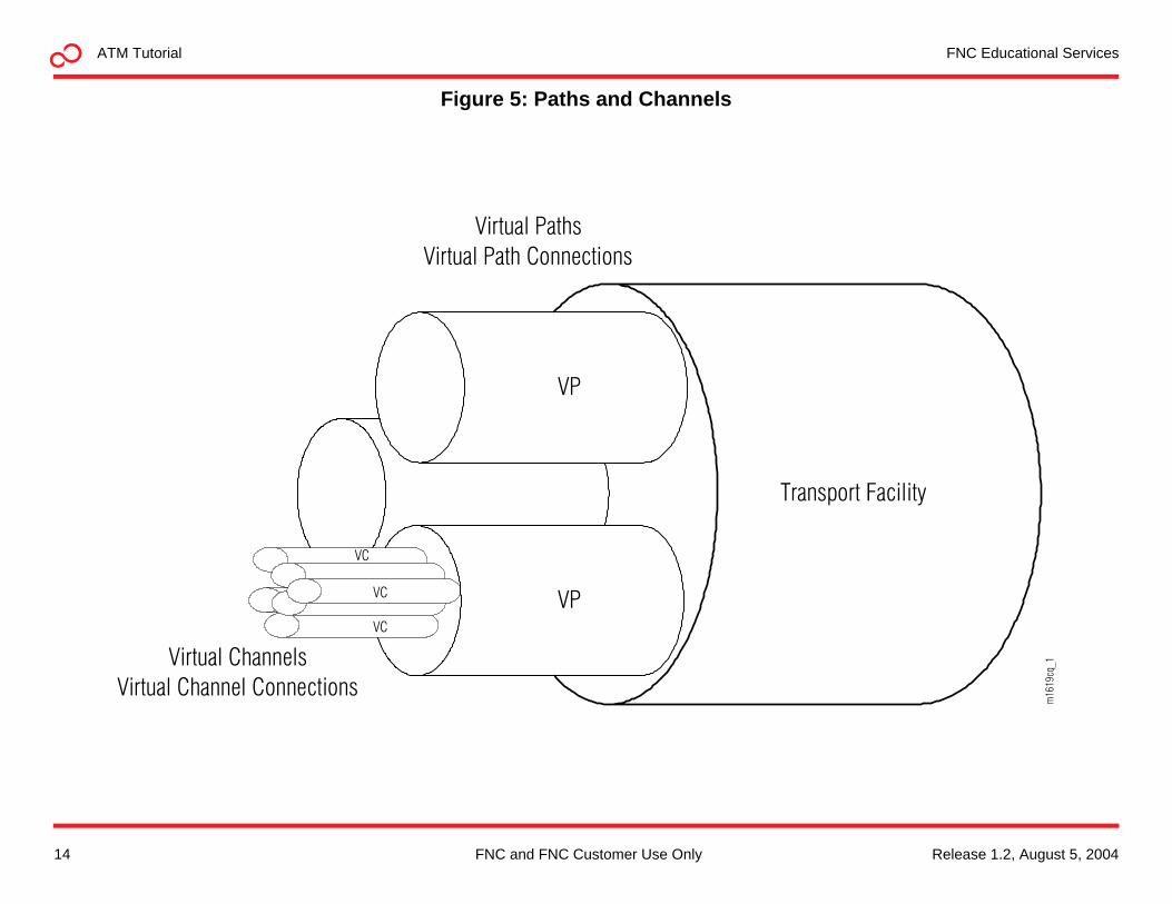
Figure 5: Paths and Channels
Transport Facility
VP
VPVC
VC
VC
Virtual Paths
Virtual Path Connections
Virtual Channels
Virtual Channel Connections
m16
19cq
_1
14 Release 1.2, August 5, 2004FNC and FNC Customer Use Only

ATM TutorialFNC Educational Services
Virtual Paths and Virtual ChannelsIn ATM, cells move on the transmission protocol using known end-to-end routes called virtual connections. These virtual connections link one communicating entity with another through what is sometimes a very complex system of physical medium links. Every transmission link can support thousands of virtual connections, depending on when and how much traffic needs to be sent. The pathways between virtual connections are virtual paths and virtual channels.
Traffic from various sources is bundled in a pipe and directed as a whole until it reaches its destination. While the path in the network can be redirected, all bundled channels arrive at their destination. The ATM pipe is a virtual path (VP) and is a concatenation of circuits in a link (see Figure 5). The action of redirecting the pipe is called VP switching (VPS).
Various sources or channels request connection to specific destinations. These channels are not fixed throughout the network and can jump from one VP to another to reach their destination. These are called virtual channels (VCs), and the redirecting of VCs is called VC switching (VCS).
ATM cells contain header VPI and VCI that keep track of where the cells are from one node or switch to another. These identifiers do not remain constant from endpoint to endpoint but change from hop to hop.
Virtual Path and Channel SwitchesSwitches join transmission resources together and make sure a cell gets from one transmission link to another. If needed, switches use buffers that hold cells until time for them to move onto the next link.
The switch checks the incoming cell’s VPI and VCI, determines the next outgoing VP and VC, and switches accordingly. The switch has the intelligence to move the cells to the appropriate next node by using switching tables that provide information for permanent or switched virtual connections.
Switched virtual connections are the preferred mode of operation as they are dynamically established. They are much like the connections established each time a phone call is made. The destination of the call is determined by dialing the number, and the network determines the links to that destination and establishes the connection. The connection is permanent until the call is finished and all call traffic is delivered in the same order it was sent.
Release 1.2, August 5, 2004 15FNC and FNC Customer Use Only

FNC Educational ServicesATM Tutorial
aCell delay variation is the change in arrival time for each cell.bBurst tolerance is how long a peak cell rate can be maintained.
Table 4: ATM Quality of Service
Service Category Network PriorityCell Delay and Delay
Variationa Cell Loss Burst Toleranceb
CBR 1 Low Low None
rt-VBR 2 Low Medium Some
nrt-VBR 3 High Medium Some
ABR 4 High Medium High
UBR 5 High High High
16 Release 1.2, August 5, 2004FNC and FNC Customer Use Only

ATM TutorialFNC Educational Services
ATM Quality of ServiceQuality of Service (QoS) performance parameters are concerned with accuracy, dependability, and speed. QoS guarantees for the five service categories (refer to Table 4) are:
• Cell Transfer Delay (CTD)—The average data transfer time across a UNI network. This time includes delays for all processes the data experiences:
- Coding and decoding
- Segmentation and reassembly
- Propagation delay
- Queuing
- Loss and recovery
• Cell Delay Variation (CDV)—A form of CTD that addresses jitter. The cells should not arrive too early (they bunch up, can’t get through quickly, and could be discarded) or too late (they can be considered lost and the whole packet could be jettisoned and reordered).
• Cell Loss Ratio (CLR)—The number of cells lost to the number of cells transmitted. CLR is determined by interaction between end stations and the ATM network and is in effect for the life of the connection.
As illustrated in Table 2 on page 13, QoS parameters apply most specifically to traffic requiring a constant bit rate. Uncompressed voice, audio, and video require quality service guarantees that assure that the signal transmitted at the highest, mots consistent bit rate is the signal received with the least amount of loss.
Only ATM can segregate traffic and provide specific delivery guarantees. This is part of an agreement between the ATM network and the source endpoint before traffic is accepted.
ATM Traffic ContractThe ATM network checks with the source to determine the specific signal requirements according to traffic characteristics. As each connection is made, traffic parameters are determined, and an agreement is reached. The ATM network provides service that falls within agreed to parameters. There parameters are:
• Peak Cell Rate (PCR) —The most cells per second the ATM network can accept and transfer for a given UNI:
- Excess cells can be discarded.
- PCR can apply to all service categories.
- PCR is the rate of the virtual circuit (for CBR service).
• Sustained Cell Rate (SCR)—The average throughput (applies to VBR services)
• Maximum Burst Size (MBS)—The largest burst of traffic the network can transmit during PCR
• Minimum Cell Rate (MCR)—The fewest number of cells per second the network agrees to transfer across a UNI (for ABR service, the rate the originating endpoint always transmits during a connection)
Note: QoS and ATM traffic contract rates are expressed as cells per second, not bits per second. 8 x 53 or 424 bits are in an ATM cell.
Release 1.2, August 5, 2004 17FNC and FNC Customer Use Only

FNC Educational ServicesATM Tutorial
Figure 6: Leaky Bucket
Peak Cell Rate
DiscardNoncompliant Cells
orTransparently
Pass intoNetwork
Peak Cell Rate
DiscardNoncompliant Cells
orTransparently
Pass intoNetwork
18 Release 1.2, August 5, 2004FNC and FNC Customer Use Only

ATM TutorialFNC Educational Services
ATM Traffic ControlConnection Admission ControlThere are many traffic control functions that take place within an ATM network. The first function, connection admission control (CAC), occurs before customer source information is admitted to the ATM network. A call is made to see if resources are available to establish an end-to-end connection that can provide the quality of service the customer requires without jeopardizing the quality of service needed for data already allowed on the network. The CAC looks at the source information to determine its peak and average cells, burstiness, and peak duration and to ascertain the quality of service the source information will require, such as cell transfer delay, cell loss ratio, and burst cell loss. If everything checks out, a connection is made, and customer information is admitted to the ATM network.
Parameter ControlsAdditional traffic control measures are usage and network parameter controls (UPC and NPC). These controls are used in UNIs and NNIs, respectively, and monitor cell traffic volume and cell routing validity. These connection controls ensure compliance of every ATM connection to its negotiated traffic contract. The leaky bucket analogy is used for cells that exceed the contract rate and are discarded (leaked out) through a hole in the bucket that is only as big as the contract required (see Figure 6).
Priority ControlThe cell loss priority (CLP) bit in the ATM cell header is used to control traffic by designating cells that are discard candidates if traffic gets backed up and priority cells must go through. Priority is determined by the quality of service the source information requested before being admitted to the ATM network.
Network Resource ManagementVirtual paths (VPs) are used as an important traffic control and network resource management tool. The paths are used for traffic aggregation and segregation, allowing cells requiring the same services to travel together, while segregating those cells that have greater or lesser priority. VPs also distribute congestion notifications that are alerts to reroute and establish connections away from congested areas.
Traffic ShapingThe ATM switch can be used to alter traffic characteristics of a cell stream to reduce peak cell rate, limit burst lengths, and minimize cell delay variation. This is done by respacing the cells in time so that congestion is reduced at subsequent switches. This is very important at times when long bursts of high priority traffic could otherwise bring lower priority traffic to a standstill.
Release 1.2, August 5, 2004 19FNC and FNC Customer Use Only

FNC Educational ServicesATM Tutorial
Figure 7: ATM Advantages
Technology• High Performance• Multimedia• Packet Switched
Services• Switched Virtual Circuits• Multiple Service Classes
Standards• Interface• Signaling• Traffic Management
Technology• High Performance• Multimedia• Packet Switched
Services• Switched Virtual Circuits• Multiple Service Classes
Standards• Interface• Signaling• Traffic Management
20 Release 1.2, August 5, 2004FNC and FNC Customer Use Only

ATM TutorialFNC Educational Services
ATM AdvantagesATM provides several advantages (see Figure 7):
• ATM fixed-length cells require lower processing overhead and produce higher transmission speeds than traditional packet switching methods.
• ATM transmits asynchronous data in a synchronous network while prioritizing time-sensitive traffic ahead of delay-tolerance traffic to ensure that quality of service is maintained.
• ATM delivers true bandwidth-on-demand (a big plus for high-speed voice, data, and video service) and uses statistical multiplexing techniques to efficiently use resources.
• ATM is application-independent, meaning it can be used as a common infrastructure for many network types, including public, private, LAN, and campus backbones.
• ATM is designed for high-performance, multimedia networking on a broad range of devices:
- PC, workstation, server network interface cards
- Switched Ethernet and token ring workgroup hubs
- Workgroup and campus ATM switches
- Enterprise network switches, multiplexers, edge and backbone switches
• International standards compliance in central office and customer premises environments allow multi-vendor operation and interoperability.
ATM DisadvantagesWhile ATM has several advantages, ATM disadvantages can be seen in three areas:
• Cost
• Complexity
• Availability
Compared with voice switches, ATM switches are still much more expensive per line. ATM was implemented before the designers intended, and ATM standards are still trying to catch up, which should help to bring down the cost of ATM equipment.
ATM equipment is very complex and intelligent. It takes a very intelligent management team and system to operate ATM successfully (that is, efficiently and cost-effectively).
ATM is not as widely available as SONET and SDH. These are older protocols that are widely accepted and very well standardized. Additionally, with the proliferation of Fast Ethernet and Gigabit Ethernet, ATM may not be necessary. This is especially true for those who transport Ethernet over already ubiquitous SONET/SDH networks.
Release 1.2, August 5, 2004 21FNC and FNC Customer Use Only

FNC Educational ServicesATM Tutorial
ATM Acronyms
AAL ATM adaptation layer IETF Internet Engineering Task Force SAR Segmentation and reassembly
ABR Available bit rate IP Internet Protocol SCR Sustained cell rate
ANSI American National Standards Institute ISDN Integrated Services Digital Network SEAL Simple and efficient layer
ATM Asynchronous Transfer Mode ITU International Telecommunication Union SMDS Switched multimegabit data service
BT Burst tolerance LAN Local area network SN Sequence number
CAC Connection admission control LANE LAN emulation SNP SN protection
CBR Constant bit rate MBS Maximum burst size SVC Switched virtual circuit
CDV Cell delay variation MCR Minimum cell rate TC Transmission convergence
CDVT CDV tolerance NNI Network-to-network interface UBR Unspecified bit rate
CER Cell error ratio NPC Network parameter control UNI User network interface
CLP Cell loss priority nrt-VBR Non-real time Variable Bit Rate UPC Usage parameter control
CLR Cell loss ratio OAM Operation, administration, and maintenance VBR Variable bit rate
CPE Customer premises equipment PCR Peak cell rate VC Virtual channel
CRC Cyclic redundancy check PDU Protocol data unit VCC VC connection
CS Convergence sublayer PM Physical medium VCI VC identifier
CTD Cell transfer delay PMD PM dependent VCS VC switching
DXI Data exchange interface PTI Payload type identifier VP Virtual path
GFC Generic flow control PVC Permanent virtual circuit VPC VP connection
HEC Header error control QoS Quality of service VPI VP identifier
IDU Interface data unit rt-VBR Real-time Variable Bit Rate WAN Wide area network
22 Release 1.2, August 5, 2004FNC and FNC Customer Use Only

ATM TutorialFNC Educational Services
Tutorial ReviewInstructions
Please read the questions below and circle the correct answer.
1. ATM has ____ service categories.
a. 10
b. 3
c. 7
d. 5
2. An ATM cell consists of _________.
a. 48 bits
b. 53 bits
c. 53 bytes
d. 48 bytes
3. There are no Quality of Service guarantees for ___ and ___ service categories.
a. ABR, UBR
b. rt-VBR, nrt-VBR
c. ABR, rt-VBR
d. UBR, CBR
4. The ATM Protocol Layer Model consists of ___ layers and ___ planes.
a. 4,3
b. 3,3
c. 3,4
d. 4,4
5. All but one are ATM advantages.
a. Rate and medium independent
b. Flexibility
c. Availability
d. Low latency
6. The two ATM Adaption Layer sublayers are ___ and ___.
a. SAR, CS
b. CRT, CPU
c. SC, SAR
d. PMD, TC
7. The ATM Adaptation Layer puts data into the _____.
a. virtual paths
b. cells
c. virtual channels
d. ATM switches
Release 1.2, August 5, 2004 23FNC and FNC Customer Use Only

FNC Educational ServicesATM Tutorial
8. ATM offers true bandwidth on demand because it is ___________.
a. fixed-length
b. asynchronous
c. packet switched
d. all of the above
9. The four bits field not used in a NNI network header is ____; four additional ____ bits used in the header.
a. GFC, VPI
b. VCI, GFC
c. GFC, CRT
d. HEC, GFC
10.The ATM QoS categories that addresses jitter is:
a. CMR
b. CTD
c. CLP
d. CDV
11. The ATM transmission link is comprised of _______ ________ within _________________.
a. virtual paths, virtual channel
b. virtual tributaries, virtual tributary groups
c. virtual channels, virtual paths
d. none of the above
12.The maximum average rate at which ATM networks agree to accept calls is the _____ cell rate.
a. peak
b. sustainable
c. median
d. mean
13.The header bits that plan all the trips but never get to go anywhere are ______.
a. VPI
b. GFC
c. VCI
d. HEC
14.An acronym for a public user network interface is:
a. UNI
b. PUNI
c. PPNI
d. NNI
24 Release 1.2, August 5, 2004FNC and FNC Customer Use Only

ATM TutorialFNC Educational Services
AnswersNote: Click on the answer to go to the tutorial
reference page.
1. d
2. c
3. a
4. a
5. c
6. a
7. b
8. b
9. a
10. d
11. a
12. a
13. b
14. d
Release 1.2, August 5, 2004 25FNC and FNC Customer Use Only

FNC Educational ServicesATM Tutorial
26 Release 1.2, August 5, 2004FNC and FNC Customer Use Only