ATM (Asynchronous Transfer Mode)
22
ATM – Asynchronous Transfer Mode Tuan
description
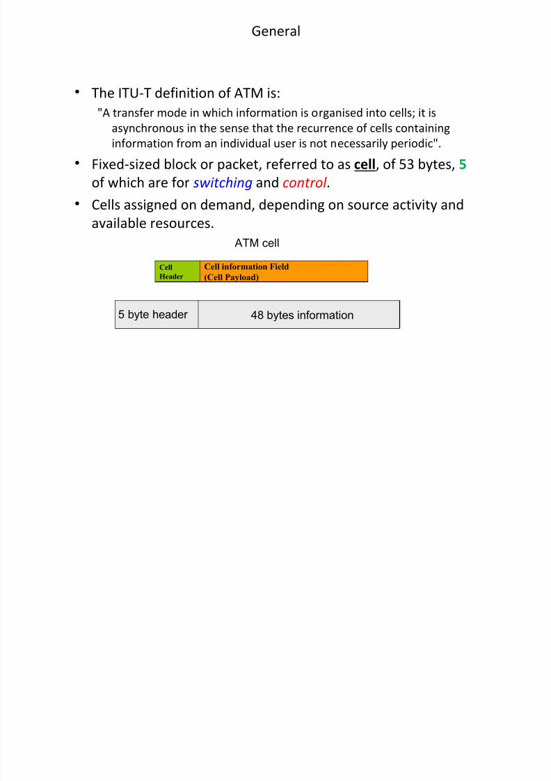
The ITU-T definition of ATM is:"A transfer mode in which information is organised into cells; it is asynchronous in the sense that the recurrence of cells containing information from an individual user is not necessarily periodic".
Transcript of ATM (Asynchronous Transfer Mode)

7/17/2019 ATM (Asynchronous Transfer Mode)
http://slidepdf.com/reader/full/atm-asynchronous-transfer-mode-568e0f0f446fe 1/26
ATM – Asynchronous Transfer Mode
Tuan
7/17/2019 ATM (Asynchronous Transfer Mode)
http://slidepdf.com/reader/full/atm-asynchronous-transfer-mode-568e0f0f446fe 2/26
General
• The ITU-T definition of ATM is:
"A transfer mode in which information is organised into cells; it is
asynchronous in the sense that the recurrence of cells containing
information from an individual user is not necessarily eriodic"!
• i#ed-si$ed %loc& or ac&et' referred to as cell' of () %ytes' 5 of which are for switching and control !
• *ells assigned on demand' deending on source activity and
availa%le resources!
Cell information Field
(Cell Payload)
Cell
Header
48 bytes information5 byte header
ATM cell

7/17/2019 ATM (Asynchronous Transfer Mode)
http://slidepdf.com/reader/full/atm-asynchronous-transfer-mode-568e0f0f446fe 3/26
ATM rocess: rom ac&etisation to cell server
• *onsider a single switch and focus on a single outut ort :
finite buffer fixed rate server
multiplexor ATMcell segmentation
variable bit rate
data bursts
high bandwidth
constant bit rate
constant bit rate
lowbandwidth
services
: ac!etiser
: ATMcell
: "eader

7/17/2019 ATM (Asynchronous Transfer Mode)
http://slidepdf.com/reader/full/atm-asynchronous-transfer-mode-568e0f0f446fe 4/26
ATM rocess: receiving station end
ATMcell de#ittering
variable bit rate
data bursts
high bandwidth
constant bit rate
constant bit ratelowbandwidthasynchronous arrival of cells
arriving ATMcells signal reconstruction
and reassebmly
7/17/2019 ATM (Asynchronous Transfer Mode)
http://slidepdf.com/reader/full/atm-asynchronous-transfer-mode-568e0f0f446fe 5/26
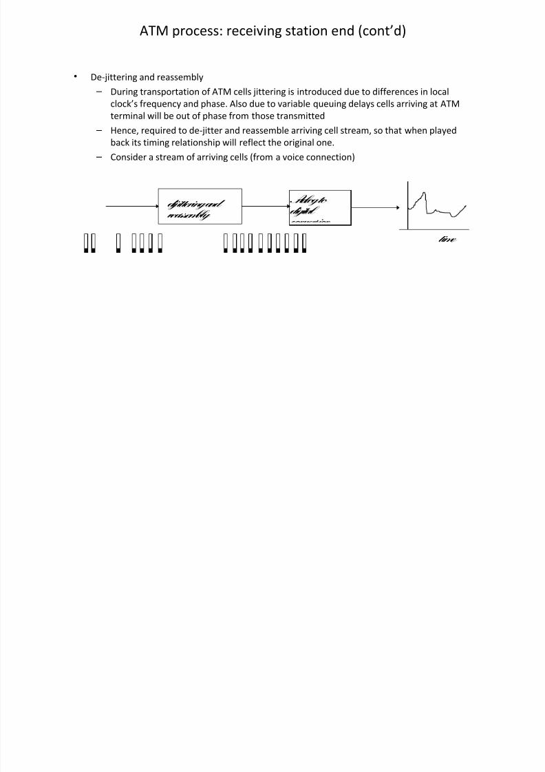
ATM rocess: receiving station end +cont,d
• .e-/ittering and reassem%ly $ .uring transortation of ATM cells /ittering is introduced due to differences in local
cloc&,s fre0uency and hase! Also due to varia%le 0ueuing delays cells arriving at ATM
terminal will %e out of hase from those transmitted
$ 1ence' re0uired to de-/itter and reassem%le arriving cell stream' so that when layed
%ac& its timing relationshi will reflect the original one!
$ *onsider a stream of arriving cells +from a voice connection
dijittering and eassembly
Analog to digital
time

7/17/2019 ATM (Asynchronous Transfer Mode)
http://slidepdf.com/reader/full/atm-asynchronous-transfer-mode-568e0f0f446fe 6/26
2ayers for ATM +cont,d
%%%
output by an
example application
output by
convergence
sublayer &'()
output by
(A* sublayer
message
'( '(
'( '( ( A *
( A *
( A *
( A *
( A *
( A *
( A *
( A *
unused
%%%'( '( ( A *
( A *
( A *
( A *
( A *
( A *
( A *
( A *
output by
ATM layer
A T M
A T M
A T M
A T M
48 bytes5+ bytes
header
header
trailer
trailer

7/17/2019 ATM (Asynchronous Transfer Mode)
http://slidepdf.com/reader/full/atm-asynchronous-transfer-mode-568e0f0f446fe 7/26
2ayers for ATM
ATM-3.U
ATM-4.U
ATM!.ATA!
Indication
ATM!.ATA!
5e0uest
Indicate
5e0uest
ATM Adatation 2ayer
+AA2
ATM 2ayer
3hysical layer +316
ATM-4.U: ATM 4ervice .ata
Unit +78 %ytes of user dataincluding A22 1eader
1igher layers
Alication
information
9ideo .ata 9oice
Alications
*onvert to correct
electrical or
otical format
orward +or receive
cell through networ&
*onversion to +from
ATM data tyes
ATM-3.U: ATM 3rocess .ata
Unit +() %yte cells
To +from ATM switch

7/17/2019 ATM (Asynchronous Transfer Mode)
http://slidepdf.com/reader/full/atm-asynchronous-transfer-mode-568e0f0f446fe 8/26
3hysical 2ayer: 3hysical Medium +3M su%-layer
• Tas& of hysical layer +316 is to transort ATM cells!
• 3hysical layer standards define fundamental schemes for %asic digital transmission to
suort ATM' including signal definitions' coding' %it timing' formats' scram%ling and
oeration and maintenance caa%ilities!
• ne asect of these standards is uni0ue to ATM: They all define a mechanism to delineate
+cell synchroni$ed ATM cells!
• At resent' wide range of hysical-layer transort otions:
$ ver 4<T=4.1 +agreed %y <T4I and ITU and T>4> - e!g! 4.1 4TM-> at >(( M%s u to
4TM->? at @!7 Gg%it=s! *ells transmitted as tri%utaries within 4.1 frame!
$ ver 3.1 +5ecs! G!B)' G!8B7 +.4> >!( M%s and <> @ M%s' .4) +7( M%s' <) +)7
M%s ' <7 +>)C M%s
$ <tc!

7/17/2019 ATM (Asynchronous Transfer Mode)
http://slidepdf.com/reader/full/atm-asynchronous-transfer-mode-568e0f0f446fe 9/26
ATM rocess for transmission

7/17/2019 ATM (Asynchronous Transfer Mode)
http://slidepdf.com/reader/full/atm-asynchronous-transfer-mode-568e0f0f446fe 10/26
ATM etwor& Interfaces
3u%lic
4witch
3u%lic
4witch
2ocal 4witch
*omuter
5outer.ata 4ervice
Unit +.4U
*omuter
I 3u%lic
4witch
I
UI
UI
UI
UI
UIUI
I - etwor& ode Interface
UI - User networ& Interface

7/17/2019 ATM (Asynchronous Transfer Mode)
http://slidepdf.com/reader/full/atm-asynchronous-transfer-mode-568e0f0f446fe 11/26
ATM *ell ormat

7/17/2019 ATM (Asynchronous Transfer Mode)
http://slidepdf.com/reader/full/atm-asynchronous-transfer-mode-568e0f0f446fe 12/26
ATM 4witching
• ATM networ&s' which are connection-oriented devices' need a virtual circuit +9* to %e set u
across the networ& rior to any data transfer!
• Two tyes of circuits include the virtual ath +93' which is identified %y a virtual ath
identifier +93I' and the channel ath' which is identified %y the virtual channel identifier
+9*I!
• Decause 9*I=93I values are locali$ed' each segment of the connection has a uni0ue 93I=9*I
com%ination! Ehen a cell travels through the networ& from the user networ& interface +UI
through the switch to the networ& node interface +I' the 93I=9*I value is changed to the
value the ne#t segment of connection uses through a rocess called a 93I=9*I translation'shown in igure %elow:

7/17/2019 ATM (Asynchronous Transfer Mode)
http://slidepdf.com/reader/full/atm-asynchronous-transfer-mode-568e0f0f446fe 13/26
ATM 4witching : Translation
• igure %elow shows the function of an ATM switch where 93I=9*I values are translated!
93I=9*I values are uni0ue er interface; however' the values can %e re-used along thenetwor&! or e#amle' in igure %elow' the 93I=9*I value of @C is used in two different
interfaces!

7/17/2019 ATM (Asynchronous Transfer Mode)
http://slidepdf.com/reader/full/atm-asynchronous-transfer-mode-568e0f0f446fe 14/26
ATM 4witching
• Virtual Channel=Virtual Path +VC=VP
$ Virtual Channel +VC connection
• connection %etween two communicating ATM end entities!
• may consist of several ATM 9* lin&s!
• reserves cell se0uence and rovides a certain 0uality of service!
• A Virtual Channel Identifier +VCI in the ATM cell header is assigned er networ&
entity-to-entity lin&' i!e! it may change across the networ& within the same 9*
connections!
$ Virtual Path +VP connection:
• Grous 9*s carried %etween two ATM entities!
• may involve many ATM 93 lin&s!
• allows for efficient and simle management of resources %y alying controls on a
small num%er of grous of connections +the 93s rather than a large num%er ofindividual connections +the 9*s!
• 9*s associated with 93s are glo%ally switched without un%undling or rocessing of
the individual 9*s!
• reduction of si$e of routing ta%les in ATM 93 switches
• allows carriers to offer Virtual Private Networks (VPNs) to cororate customers

7/17/2019 ATM (Asynchronous Transfer Mode)
http://slidepdf.com/reader/full/atm-asynchronous-transfer-mode-568e0f0f446fe 15/26
9irtual 3ath and 9irtual *ircuit *oncet
VCI =1 (text)
VCI =2 (voice)
VCI =3 (video)
TRA!"I!!I# PATH
Text
Voice
Video
AT" et$or%
Interface
Virt&al Pat'
VP
VC

7/17/2019 ATM (Asynchronous Transfer Mode)
http://slidepdf.com/reader/full/atm-asynchronous-transfer-mode-568e0f0f446fe 16/26
ATM switching +cont,d
• *ell multile#ing and switching
$ for more than one ATM connection' ATM layer is resonsi%le for the multile#ing
function $ 9* %asic routing entity for switched services! 1andled in 9* multile#ers=demultile#ers
and switches!
$ 9*s are aggregated in 93s which may %e routed through multile#ers=demultile#ers
and 93 switches=cross connects
, , , ,
,' ,' ,'
,
,'' ,''
,' ,'
, ATM
switch
,-,' ATM
switch
transmission pathvirtual path
virtual
channels

7/17/2019 ATM (Asynchronous Transfer Mode)
http://slidepdf.com/reader/full/atm-asynchronous-transfer-mode-568e0f0f446fe 17/26
4EIT*1IG 9*s and 93s
• 5outing functions for 93s are erformed at a 93 switch!
• This routing involves translation of the 93I values of the incoming 93 lin&s to the 93I values
of the outgoing 93 lin&s! 9*I values remain unchanged!
• 9* switches terminate %oth 9* lin&s and necessarily 93 lin&s!
• 93I and 9*I translation is erformed!
VP Switch/Cross Connect
VPI1
VPI2
VPI3
VPI4
VPI5
VPI6
VCI 21
VCI 22
VCI 23
VCI 24
VCI 25
VCI 24
VCI 23
VCI 24
VCI 25
VCI 24
VCI 21
VCI 22
VP Switching
7/17/2019 ATM (Asynchronous Transfer Mode)
http://slidepdf.com/reader/full/atm-asynchronous-transfer-mode-568e0f0f446fe 18/26
93 and 9* 4EIT*1IG
VCI 23
VCI 24
VPI 2
VCI 25
VCI 21
VPI 4
VPI 5
VCI 23
VCI 24
VCI 25
VCI 21
VC !$itc'Cro Connect

7/17/2019 ATM (Asynchronous Transfer Mode)
http://slidepdf.com/reader/full/atm-asynchronous-transfer-mode-568e0f0f446fe 19/26
1eader 3rocessing
• 1eader translation and interretation
$ Ehen cells enter the switch' their headers are analysed!
• for ATM cross-connect system' only 93I field of the header is analysed and used for
routing!
• for ATM VCI switch' %oth 93I and 9*I field are analysed and used for routing!
$ Idle cells are discarded from the cell stream and all other cells are send to the headerinterpreter !
$ In general' the header is interreted using a ta%le!
• or each valid 9* lin&' an entry e#ists in this ta%le! This ta%le contains at least @
entries er inde#:
$ >! The destination ort num%er
$ @! The new 9*I=93I value

7/17/2019 ATM (Asynchronous Transfer Mode)
http://slidepdf.com/reader/full/atm-asynchronous-transfer-mode-568e0f0f446fe 20/26
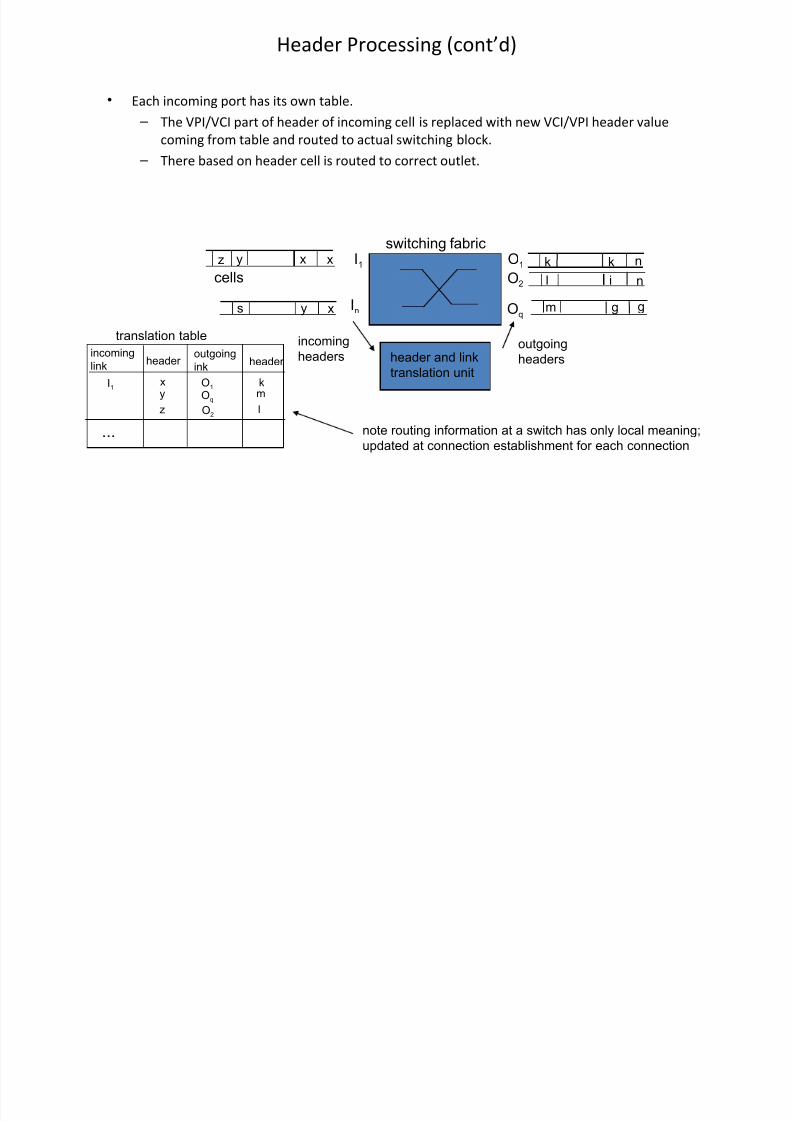
1eader 3rocessing +cont,d
• <ach incoming ort has its own ta%le!
$ The 93I=9*I art of header of incoming cell is relaced with new 9*I=93I header valuecoming from ta%le and routed to actual switching %loc&!
$ There %ased on header cell is routed to correct outlet!
xxy
xys
n!!
ggm
nil
.
cells
/0
/n
10
12
13
header and lin!
translation unit
incoming
headers outgoingheaders
translation table
incominglin!
outgoing
in!header header
/0x
.
y10
!m
l
13
12
%%% note routing information at a switch has only local meaning
updated at connection establishment for each connection
switching fabric

7/17/2019 ATM (Asynchronous Transfer Mode)
http://slidepdf.com/reader/full/atm-asynchronous-transfer-mode-568e0f0f446fe 21/26
ATM 4witching : *AM
• The time re0uired to comute 93I=9*I translations is critical in order to determine the
erformance of ATM networ&s!
• *AM can act as an address translator for loo&-u ta%les +2UTs in ATM switches and erform
93I=9*I translation 0uic&ly!
• 93I=9*I fields from the ATM controller are comared against a list of current connections
stored in the *AM array!
• *AM generates an address that is used to access an em%edded 5AM' where 93I=9*I maing
data and other connection information are stored!
• 93I=9*I data from 5AM is added on to the cell and sent to the switch' as shown in igure
%elow :

7/17/2019 ATM (Asynchronous Transfer Mode)
http://slidepdf.com/reader/full/atm-asynchronous-transfer-mode-568e0f0f446fe 22/26
.iagram of the >?#>? 4witching ode
Structure of the Control Chip

7/17/2019 ATM (Asynchronous Transfer Mode)
http://slidepdf.com/reader/full/atm-asynchronous-transfer-mode-568e0f0f446fe 23/26
An ATM ode

7/17/2019 ATM (Asynchronous Transfer Mode)
http://slidepdf.com/reader/full/atm-asynchronous-transfer-mode-568e0f0f446fe 24/26
Generating 93-AI4=5.I and 9*-AI4=5.I tye AM cells

7/17/2019 ATM (Asynchronous Transfer Mode)
http://slidepdf.com/reader/full/atm-asynchronous-transfer-mode-568e0f0f446fe 25/26
ormat of AM cells

7/17/2019 ATM (Asynchronous Transfer Mode)
http://slidepdf.com/reader/full/atm-asynchronous-transfer-mode-568e0f0f446fe 26/26
Than& 6ou F