Atlas Copco Oil-injected rotary screw compressors€¦ · Atlas Copco Oil-injected rotary screw...
74
Atlas Copco Oil-injected rotary screw compressors GX 2 EP, GX 3 EP, GX 4 EP, GX 5 EP, GX 7 EP Instruction book
-
Upload
nguyentruc -
Category
Documents
-
view
285 -
download
5
Transcript of Atlas Copco Oil-injected rotary screw compressors€¦ · Atlas Copco Oil-injected rotary screw...

Atlas CopcoOil-injected rotary screw compressors
GX 2 EP, GX 3 EP, GX 4 EP, GX 5 EP, GX 7 EP
Instruction book


Atlas CopcoOil-injected rotary screw compressors
GX 2 EP, GX 3 EP, GX 4 EP, GX 5 EP, GX 7 EPFrom following serial No. onwards: CAI 544 242
Instruction bookOriginal instructions
Copyright noticeAny unauthorized use or copying of the contents or any part thereof is prohibited.
This applies in particular to trademarks, model denominations, part numbers and drawings.
This instruction book is valid for CE as well as non-CE labelled machines. It meets therequirements for instructions specified by the applicable European directives as identifiedin the Declaration of Conformity.
2012 - 03
No. 2920 7105 30
www.atlascopco.com

Table of contents
1 Safety precautions..........................................................................................................4
1.1 SAFETY ICONS...................................................................................................................................4
1.2 SAFETY PRECAUTIONS, GENERAL...........................................................................................................4
1.3 SAFETY PRECAUTIONS DURING INSTALLATION...........................................................................................5
1.4 SAFETY PRECAUTIONS DURING OPERATION..............................................................................................6
1.5 SAFETY PRECAUTIONS DURING MAINTENANCE OR REPAIR...........................................................................7
2 General description........................................................................................................9
2.1 INTRODUCTION...................................................................................................................................9
2.2 AIR FLOW.......................................................................................................................................11
2.3 OIL SYSTEM....................................................................................................................................14
2.4 COOLING SYSTEM.............................................................................................................................16
2.5 REGULATING SYSTEM........................................................................................................................17
2.6 CONTROL PANEL .............................................................................................................................19
2.7 ELECTRICAL DIAGRAMS......................................................................................................................20
2.8 PROTECTION OF COMPRESSOR............................................................................................................27
2.9 AIR DRYER......................................................................................................................................29
3 Installation.....................................................................................................................30
3.1 INSTALLATION PROPOSAL...................................................................................................................30
3.2 DIMENSION DRAWINGS.......................................................................................................................33
3.3 ELECTRICAL CONNECTIONS ................................................................................................................37
3.4 PICTOGRAPHS.................................................................................................................................38
4 Operating instructions.................................................................................................40
4.1 INITIAL START-UP..............................................................................................................................40
4.2 STARTING.......................................................................................................................................42
4.3 STOPPING.......................................................................................................................................44
Instruction book
2 2920 7105 30

4.4 TAKING OUT OF OPERATION................................................................................................................46
5 Maintenance..................................................................................................................48
5.1 PREVENTIVE MAINTENANCE SCHEDULE..................................................................................................48
5.2 DRIVE MOTOR .................................................................................................................................49
5.3 OIL SPECIFICATIONS..........................................................................................................................49
5.4 OIL, FILTER AND SEPARATOR CHANGE .................................................................................................50
5.5 STORAGE AFTER INSTALLATION...........................................................................................................52
5.6 SERVICE KITS..................................................................................................................................52
6 Adjustments and servicing procedures.....................................................................53
6.1 AIR FILTER......................................................................................................................................53
6.2 COOLERS.......................................................................................................................................54
6.3 SAFETY VALVE ................................................................................................................................54
6.4 BELT SET EXCHANGE AND TENSIONING ................................................................................................55
7 Problem solving............................................................................................................57
8 Technical data...............................................................................................................60
8.1 READINGS ON CONTROL PANEL...........................................................................................................60
8.2 ELECTRIC CABLE SIZE.......................................................................................................................60
8.3 SETTINGS FOR OVERLOAD RELAY AND FUSES.........................................................................................61
8.4 REFERENCE CONDITIONS AND LIMITATIONS............................................................................................63
8.5 COMPRESSOR DATA..........................................................................................................................63
9 Instructions for use......................................................................................................67
10 Guidelines for inspection.............................................................................................68
11 Pressure equipment directives...................................................................................69
12 Declaration of conformity............................................................................................70
Instruction book
2920 7105 30 3

1 Safety precautions
1.1 Safety icons
Explanation
Danger for life
Warning
Important note
1.2 Safety precautions, general
General precautions
1. The operator must employ safe working practices and observe all related work safety requirements andregulations.
2. If any of the following statements does not comply with the applicable legislation, the stricter of the twoshall apply.
3. Installation, operation, maintenance and repair work must only be performed by authorized, trained,specialized personnel.
4. The compressor is not considered capable of producing air of breathing quality. For air of breathing quality,the compressed air must be adequately purified according to the applicable legislation and standards.
5. Before any maintenance, repair work, adjustment or any other non-routine checks, stop the compressor,press the emergency stop button, switch off the voltage and depressurize the compressor. In addition, thepower isolating switch must be opened and locked.On units powered by a frequency converter, wait six minutes before starting any electrical repair.
If the machine is equipped with an automatic restart after voltage failure function and if thisfunction is active, be aware that the machine will restart automatically when the power isrestored if it was running when the power was interrupted!
6. Never play with compressed air. Do not apply the air to your skin or direct an air stream at people. Neveruse the air to clean dirt from your clothes. When using the air to clean equipment, do so with extremecaution and wear eye protection.
7. The owner is responsible for maintaining the unit in safe operating condition. Parts and accessories shallbe replaced if unsuitable for safe operation.
8. It is not allowed to walk or stand on the unit or on its components.
Instruction book
4 2920 7105 30

1.3 Safety precautions during installationAll responsibility for any damage or injury resulting from neglecting these precautions, ornon observance of the normal caution and care required for installation, operation,maintenance and repair, even if not expressly stated, will be disclaimed by themanufacturer.
Precautions during installation
1. The machine must only be lifted using suitable equipment in accordance with the applicable safetyregulations. Loose or pivoting parts must be securely fastened before lifting. It is strictly forbidden todwell or stay in the risk zone under a lifted load. Lifting acceleration and deceleration must be kept withinsafe limits. Wear a safety helmet when working in the area of overhead or lifting equipment.
2. The unit is designed for indoor use. If the unit is installed outdoors, special precautions must be taken;consult your supplier.
3. Place the machine where the ambient air is as cool and clean as possible. If necessary, install a suctionduct. Never obstruct the air inlet. Care must be taken to minimize the entry of moisture at the inlet air.
4. Any blanking flanges, plugs, caps and desiccant bags must be removed before connecting the pipes.5. Air hoses must be of correct size and suitable for the working pressure. Never use frayed, damaged or
worn hoses. Distribution pipes and connections must be of the correct size and suitable for the workingpressure.
6. The aspirated air must be free of flammable fumes, vapours and particles, e.g. paint solvents, that can leadto internal fire or explosion.
7. Arrange the air intake so that loose clothing worn by people cannot be sucked in.8. Ensure that the discharge pipe from the compressor to the aftercooler or air net is free to expand under
heat and that it is not in contact with or close to flammable materials.9. No external force may be exerted on the air outlet valve; the connected pipe must be free of strain.10. If remote control is installed, the machine must bear a clear sign stating: DANGER: This machine is
remotely controlled and may start without warning.The operator has to make sure that the machine is stopped and that the isolating switch is open and lockedbefore any maintenance or repair. As a further safeguard, persons switching on remotely controlledmachines shall take adequate precautions to ensure that there is no one checking or working on themachine. To this end, a suitable notice shall be affixed to the start equipment.
11. Air-cooled machines must be installed in such a way that an adequate flow of cooling air is available andthat the exhausted air does not recirculate to the compressor air inlet or cooling air inlet.
12. The electrical connections must correspond to the applicable codes. The machines must be earthed andprotected against short circuits by fuses in all phases. A lockable power isolating switch must be installednear the compressor.
13. On machines with automatic start/stop system or if the automatic restart function after voltage failure isactivated, a sign stating "This machine may start without warning" must be affixed near the instrumentpanel.
14. In multiple compressor systems, manual valves must be installed to isolate each compressor. Non-returnvalves (check valves) must not be relied upon for isolating pressure systems.
15. Never remove or tamper with the safety devices, guards or insulation fitted on the machine. Every pressurevessel or auxiliary installed outside the machine to contain air above atmospheric pressure must beprotected by a pressure relieving device or devices as required.
16. Piping or other parts with a temperature in excess of 70˚C (158˚F) and which may be accidentally touchedby personnel in normal operation must be guarded or insulated. Other high temperature piping must beclearly marked.
17. For water-cooled machines, the cooling water system installed outside the machine has to be protected bya safety device with set pressure according to the maximum cooling water inlet pressure.
Instruction book
2920 7105 30 5

18. If the ground is not level or can be subject to variable inclination, consult the manufacturer.
Also consult following safety precautions: Safety precautions during operation and Safetyprecautions during maintenance.These precautions apply to machinery processing or consuming air or inert gas.Processing of any other gas requires additional safety precautions typical to the applicationwhich are not included herein.Some precautions are general and cover several machine types and equipment; hencesome statements may not apply to your machine.
1.4 Safety precautions during operationAll responsibility for any damage or injury resulting from neglecting these precautions, ornon observance of the normal caution and care required for installation, operation,maintenance and repair, even if not expressly stated, will be disclaimed by themanufacturer.
Precautions during operation
1. Never touch any piping or components of the compressor during operation.2. Use only the correct type and size of hose end fittings and connections. When blowing through a hose or
air line, ensure that the open end is held securely. A free end will whip and may cause injury. Make surethat a hose is fully depressurized before disconnecting it.
3. Persons switching on remotely controlled machines shall take adequate precautions to ensure that thereis no one checking or working on the machine. To this end, a suitable notice shall be affixed to the remotestart equipment.
4. Never operate the machine when there is a possibility of taking in flammable or toxic fumes, vapors orparticles.
5. Never operate the machine below or in excess of its limit ratings.6. Keep all bodywork doors shut during operation. The doors may be opened for short periods only, e.g. to
carry out routine checks. Wear ear protectors when opening a door.On compressors without bodywork, wear ear protection in the vicinity of the machine.
7. People staying in environments or rooms where the sound pressure level reaches or exceeds 80 dB(A)shall wear ear protectors.
8. Periodically check that:• All guards are in place and securely fastened• All hoses and/or pipes inside the machine are in good condition, secure and not rubbing• There are no leaks• All fasteners are tight• All electrical leads are secure and in good order• Safety valves and other pressure relief devices are not obstructed by dirt or paint• Air outlet valve and air net, i.e. pipes, couplings, manifolds, valves, hoses, etc. are in good repair, free
of wear or abuse9. If warm cooling air from compressors is used in air heating systems, e.g. to warm up a workroom, take
precautions against air pollution and possible contamination of the breathing air.10. On water-cooled compressors using open circuit cooling towers, protective measures must be taken to
avoid the growth of harmful bacteria such as Legionella or pneumophila bacteria.11. Do not remove any of, or tamper with, the sound-damping material.
Instruction book
6 2920 7105 30

12. Never remove or tamper with the safety devices, guards or insulations fitted on the machine. Every pressurevessel or auxiliary installed outside the machine to contain air above atmospheric pressure shall beprotected by a pressure relieving device or devices as required.
Also consult following safety precautions: Safety precautions during installation and Safetyprecautions during maintenance.These precautions apply to machinery processing or consuming air or inert gas.Processing of any other gas requires additional safety precautions typical to the applicationwhich are not included herein.Some precautions are general and cover several machine types and equipment; hencesome statements may not apply to your machine.
1.5 Safety precautions during maintenance or repairAll responsibility for any damage or injury resulting from neglecting these precautions, ornon observance of the normal caution and care required for installation, operation,maintenance and repair, even if not expressly stated, will be disclaimed by themanufacturer.
Precautions during maintenance or repair
1. Always use the correct safety equipment (such as safety glasses, gloves, safety shoes, etc.).2. Use only the correct tools for maintenance and repair work.3. Use only genuine spare parts.4. All maintenance work shall only be undertaken when the machine has cooled down.5. A warning sign bearing a legend such as "Work in progress; do not start" shall be attached to the starting
equipment.6. Persons switching on remotely controlled machines shall take adequate precautions to ensure that there
is no one checking or working on the machine. To this end, a suitable notice shall be affixed to the remotestart equipment.
7. Close the compressor air outlet valve before connecting or disconnecting a pipe.8. Before removing any pressurized component, effectively isolate the machine from all sources of pressure
and relieve the entire system of pressure.9. Never use flammable solvents or carbon tetrachloride for cleaning parts. Take safety precautions against
toxic vapours of cleaning liquids.10. Scrupulously observe cleanliness during maintenance and repair. Keep dirt away by covering the parts
and exposed openings with a clean cloth, paper or tape.11. Never weld or perform any operation involving heat near the oil system. Oil tanks must be completely
purged, e.g. by steam cleaning, before carrying out such operations. Never weld on, or in any way modify,pressure vessels.
12. Whenever there is an indication or any suspicion that an internal part of a machine is overheated, themachine shall be stopped but no inspection covers shall be opened before sufficient cooling time haselapsed; this to avoid the risk of spontaneous ignition of the oil vapour when air is admitted.
13. Never use a light source with open flame for inspecting the interior of a machine, pressure vessel, etc.14. Make sure that no tools, loose parts or rags are left in or on the machine.15. All regulating and safety devices shall be maintained with due care to ensure that they function properly.
They may not be put out of action.16. Before clearing the machine for use after maintenance or overhaul, check that operating pressures,
temperatures and time settings are correct. Check that all control and shut-down devices are fitted and that
Instruction book
2920 7105 30 7

they function correctly. If removed, check that the coupling guard of the compressor drive shaft has beenreinstalled.
17. Every time the separator element is renewed, examine the discharge pipe and the inside of the oil separatorvessel for carbon deposits; if excessive, the deposits should be removed.
18. Protect the motor, air filter, electrical and regulating components, etc. to prevent moisture from enteringthem, e.g. when steam cleaning.
19. Make sure that all sound-damping material and vibration dampers, e.g. damping material on the bodyworkand in the air inlet and outlet systems of the compressor, is in good condition. If damaged, replace it bygenuine material from the manufacturer to prevent the sound pressure level from increasing.
20. Never use caustic solvents which can damage materials of the air net, e.g. polycarbonate bowls.21. The following safety precautions are stressed when handling refrigerant:
• Never inhale refrigerant vapours. Check that the working area is adequately ventilated; if required, usebreathing protection.
• Always wear special gloves. In case of refrigerant contact with the skin, rinse the skin with water. Ifliquid refrigerant contacts the skin through clothing, never tear off or remove the latter; flushabundantly with fresh water over the clothing until all refrigerant is flushed away; then seek medicalfirst aid.
Also consult following safety precautions: Safety precautions during installation and Safetyprecautions during operation.These precautions apply to machinery processing or consuming air or inert gas.Processing of any other gas requires additional safety precautions typical to the applicationwhich are not included herein.Some precautions are general and cover several machine types and equipment; hencesome statements may not apply to your machine.
Instruction book
8 2920 7105 30

2 General description
2.1 Introduction
Introduction
GX 2 EP, GX 3 EP, GX 4 EP, GX 5 EP and GX 7 EP are air-cooled, single-stage, oil-injected screwcompressors, driven by an electric motor.
The compressors are belt driven.
The compressors are enclosed in sound-insulating bodywork.
An easy-to-operate control panel is provided, including the start/stop switch and the emergency stop button.A cabinet housing the regulator, pressure switch and motor starter is integrated into the bodywork.
Pack versions do not include an air dryer.
Full-Feature versions are fitted with an air dryer (DR). The dryer removes moisture from the compressed airby cooling the air to near the freezing point and automatically draining the condensate.
Floor-mounted model
The compressor is installed directly on the floor.
The floor-mounted model is available as Pack version only.
GX 5 Pack EP, floor-mounted
Ref. Description1 Control panel
Instruction book
2920 7105 30 9

Tank-mounted model
Tank-mounted units are supplied with an air receiver of 200 l (52.80 US gal / 44 Imp gal / 7 cu.ft) and areavailable in Pack and Full-Feature version.
GX 5 FF EP, tank-mounted
Ref. Description1 Control panelAO Air outletAR Air receiverDm2 Condensate drain valve, air receiverSV Safety valveDR Integrated dryer
Instruction book
10 2920 7105 30

2.2 Air flow
Pack
Air flow, floor-mounted Pack units
Instruction book
2920 7105 30 11

Air flow, tank-mounted Pack units
Air drawn in through air filter (AF) and open inlet valve (IV) is compressed in compressor element (E).Compressed air and oil flow into oil separator/tank (OT) where most of the oil is removed by centrifugalaction. The remaining oil is removed by oil separator (OS). The air flows to the outlet (AO) via minimumpressure valve (Vp).
Instruction book
12 2920 7105 30
Full-Feature
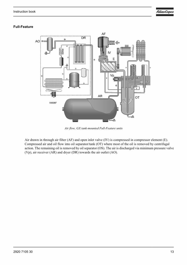
Air flow, GX tank-mounted Full-Feature units
Air drawn in through air filter (AF) and open inlet valve (IV) is compressed in compressor element (E).Compressed air and oil flow into oil separator/tank (OT) where most of the oil is removed by centrifugalaction. The remaining oil is removed by oil separator (OS). The air is discharged via minimum pressure valve(Vp), air receiver (AR) and dryer (DR) towards the air outlet (AO).
Instruction book
2920 7105 30 13
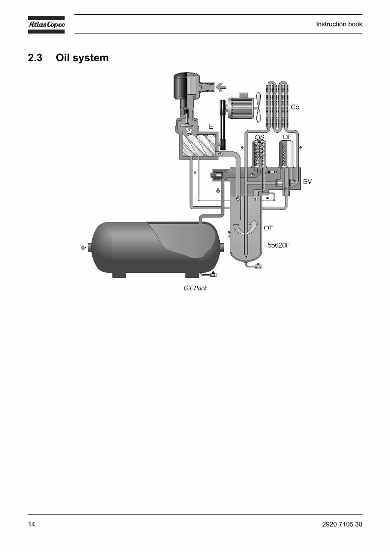
2.3 Oil system
GX Pack
Instruction book
14 2920 7105 30

GX Full-Feature
Air pressure in the oil separator tank (OT) forces the oil from the tank to compressor element (E) via oil cooler(Co) and oil filter (OF). Compressed air and oil flow into oil separator/tank (OT) where most of the oil isseparated from the air by centrifugal action. The remaining oil is removed by oil separator (OS) and returnsto the oil circuit via a separate line. The minimum pressure valve (Vp - see section Air flow) ensures a minimalpressure in the tank, required for oil circulation under all circumstances.
The oil circuit has a thermostatic bypass valve (BV). The oil cooler is bypassed until the oil is warm.
Instruction book
2920 7105 30 15

2.4 Cooling system
Pack units
Instruction book
16 2920 7105 30

Full-Feature units
A fan on the drive motor shaft provides air flow to cool the oil and the other components of the compressor.On tank-mounted compressors, the air receiver is used as air cooler. The condensate is drained manually.
The dryer (DR) of Full-Feature versions has a separate cooling fan and an automatic condensate drain (seealso section Air dryer).
2.5 Regulating system
GX 2 up to GX 5
The main components of the regulating system are:
Instruction book
2920 7105 30 17

• Pressure switch (PSR11)• Blow-off valve (Y1)
The contacts of pressure switch (PSR11) open and close at preset pressures. During loaded operation, thecontacts are closed: the motor is running.
When the working pressure reaches the upper limit, the contacts of the pressure switch open: the motor stops.Blow-off valve (Y1) opens and the pressure in the air/oil separator is released. When the working pressuredecreases to the pre-set minimum pressure, the contacts of the pressure switch close and the motor restarts.Blow-off valve Y1 closes and compressed air supply is resumed.
GX 7
Detail view of unloader assembly (UA)
The main components of the regulating system are:
• Pressure switch, which opens and closes at preset pressure limits. See also section Protection of thecompressor.
• Unloader (UA), including inlet valve (IV) and unloading valve (UV).• Loading solenoid valve (Y1).
As long as the working pressure is below the preset maximum, the solenoid valve is energised, allowingcontrol air to the unloader: the inlet valve opens completely and the unloading valve closes completely. Thecompressor will run fully loaded (100% output).
When the working pressure reaches the maximum limit, the solenoid valve is de-energised, venting the controlair: the inlet valve closes completely and the unloading valve opens completely. The compressor will rununloaded (0% output). If the compressor keeps running unloaded for an uninterrupted period of 240 seconds,it will be stopped. If the pressure reaches the minimum pressure level before the 240 seconds are reached, thecompressor will automatically start running loaded again.
The compressor will automatically restart when the net pressure drops to the minimum limit.
Instruction book
18 2920 7105 30

2.6 Control panel
Control panel GX 2 up to GX 5 EP
Control panel GX 7 EP
Reference Designation Designation1 Main switch -
emergency switchTo power the unit. Also used to stop the compressor in the eventof an emergency and to reset the thermal overload of the electricmotor by switching it to 0 and back to I.
3 Dryer ON/OFF switch (On Full-Feature units)Gpa Pressure gauge The pointer indicates the actual working pressure.Hm Hour meter Indicates the total running time.H1 Lamp Lights up when the machine is operating.S Switch Start/Stop switch (GX 2 EP up to GX 5 EP)
Load/unload switch (GX 7 EP)
Instruction book
2920 7105 30 19

2.7 Electrical diagrams
Service diagram GX 2 - IEC - 1 ph
Service diagram GX 2 up to GX 5 - IEC - 3 ph DOL
Instruction book
20 2920 7105 30

Service diagram GX 2 up to GX 5 - IEC - 3 ph Y-D
Single phase dryer - 230 V 50/60 Hz
Instruction book
2920 7105 30 21

Electrical diagram GX 2 - cULus - 1 ph
Electrical diagram GX 4 and GX 5 - cULus - 1 ph
Instruction book
22 2920 7105 30

Electrical diagram GX 2 up to GX 5 - cULus - 200-208-230-460 V 3 ph
Settings GX 2 up to GX 5 for 208-230-460 V 3 ph
Instruction book
2920 7105 30 23

Electrical diagram 575 V 60 Hz cULus
Single phase dryer - 115 V 60 Hz
Text on image
(1) Main switch and fuses to be installed by customer.
Instruction book
24 2920 7105 30

GX 7 EP
IEC units with Y-D start
Instruction book
2920 7105 30 25
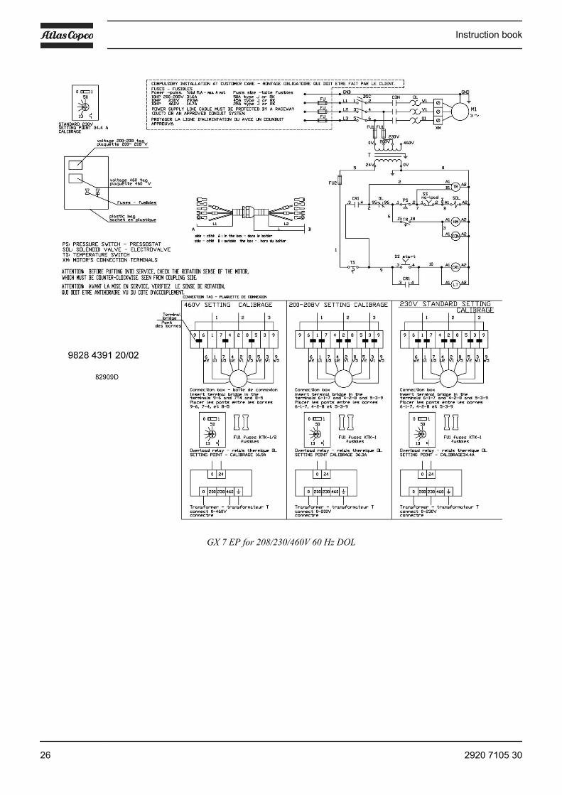
GX 7 EP for 208/230/460V 60 Hz DOL
Instruction book
26 2920 7105 30

Diagram for 575 V CSA-UL
Fuses and main switch to be installed by the customer. For full details, always consult the complete servicediagram, included in the cubicle of the compressor.
2.8 Protection of compressor
Safety valve on the compressor
Instruction book
2920 7105 30 27

Safety valve on the air receiver (tank-mounted units)
Reference Designation FunctionIG (IEC)OL (cULus)See also sectionElectrical diagrams
Motor overload relay To shut down the compressor in case the motor currentis too high.
TSH (IEC), TS(cULus)See also sectionElectrical diagrams
Temperature shut-downswitch
To shut down the compressor if the temperature at theoutlet of the compressor element is too high.
SV Safety valve To protect the air outlet system if the outlet pressureexceeds the opening pressure of the valve.
After tripping of the temperature protection: switch off the voltage and depressurise. Check and remedy. SeeProblem solving. Wait a few minutes to let the machine cool down. To reset and restart, switch on the voltageand press the red reset button after unscrewing its cover: the machine will restart.
Instruction book
28 2920 7105 30

2.9 Air dryer
Air dryer (Full-Feature compressors)
Wet compressed air (B) enters the dryer. The air then flows through a heat exchanger (2) where refrigerantevaporates, withdrawing heat from the air. The cold air then flows through a condensate trap (1) whichseparates condensate from the air. The condensate is automatically drained and this is regulated by a timer.The dried air is then discharged from the dryer.
Instruction book
2920 7105 30 29

3 Installation
3.1 Installation proposal
Outdoor/altitude operation
If the compressor is installed outdoors or if the ambient temperature can be below 0˚C (32˚F), precautionsmust be taken. In this case, and also if operating at high altitude, consult Atlas Copco.
Moving/lifting
Transport by a pallet truck
To prevent a tank-mounted model from falling over during transport by a pallet truck: pushthe forks underneath the air receiver and place a wooden beam (1) (cross-section approx.4 x 6 cm / 1.6 x 2.4 in) through the supports on both sides of the receiver. While holdingthe compressor, slowly lift the forks until the receiver is secured between the beams.
Instruction book
30 2920 7105 30

Installation proposal
Installation proposal, Floor-mounted GX
Ref. Description(6) Outlet valve
Installation proposal, tank-mounted GX
Ref. Description/recommendation1 Isolating switch, compressor
Instruction book
2920 7105 30 31

Ref. Description/recommendation2 Isolating switch, dryer3 Front panel, compressor4 Dryer(1) Minimum 1.5 m(2) Space for maintenance, minimum 2 m(3) Single-phase dryer supply(4) Three-phase screw compressor supply(5) The power cable should be protected so that it complies with local codes
Step Action1 Install the compressor on a solid, level floor suitable for taking the weight.
The recommended minimum distance between the top of the unit and the ceiling is 1.5 m (58.5 in).The minimum distance between the wall and the back of the compressor must be 200 mm (7.8 in).Floor-mounted versions must be installed with suitable air receiver.The pipes between a floor-mounted compressor and air receiver are hot.
2 Position of the compressed air outlet valve.Close the valve.Connect the air net to the valve.
3 The pressure drop over the air delivery pipe can be calculated as follows:Δp = (L x 450 x Qc
1.85) / (d5 x P), withd = Inner diameter of the pipe in mmΔp = Pressure drop in bar (recommended maximum: 0.1 bar (1.5 psi))L = Length of the pipe in mP = Absolute pressure at the compressor outlet in barQc = Free air delivery of the compressor in l/s
4 Ventilation: the inlet grids and ventilation fan should be installed in such a way that any recirculationof cooling air to the compressor or dryer is avoided.
5 Lay out the condensate drain flexible from timer drain (T) as well as the flexible from condensatedrain valve (4) towards a drain collector. The drain pipes to the drain collector must not dip into thewater of the drain collector. See the Starting section for the location of the components.
Instruction book
32 2920 7105 30
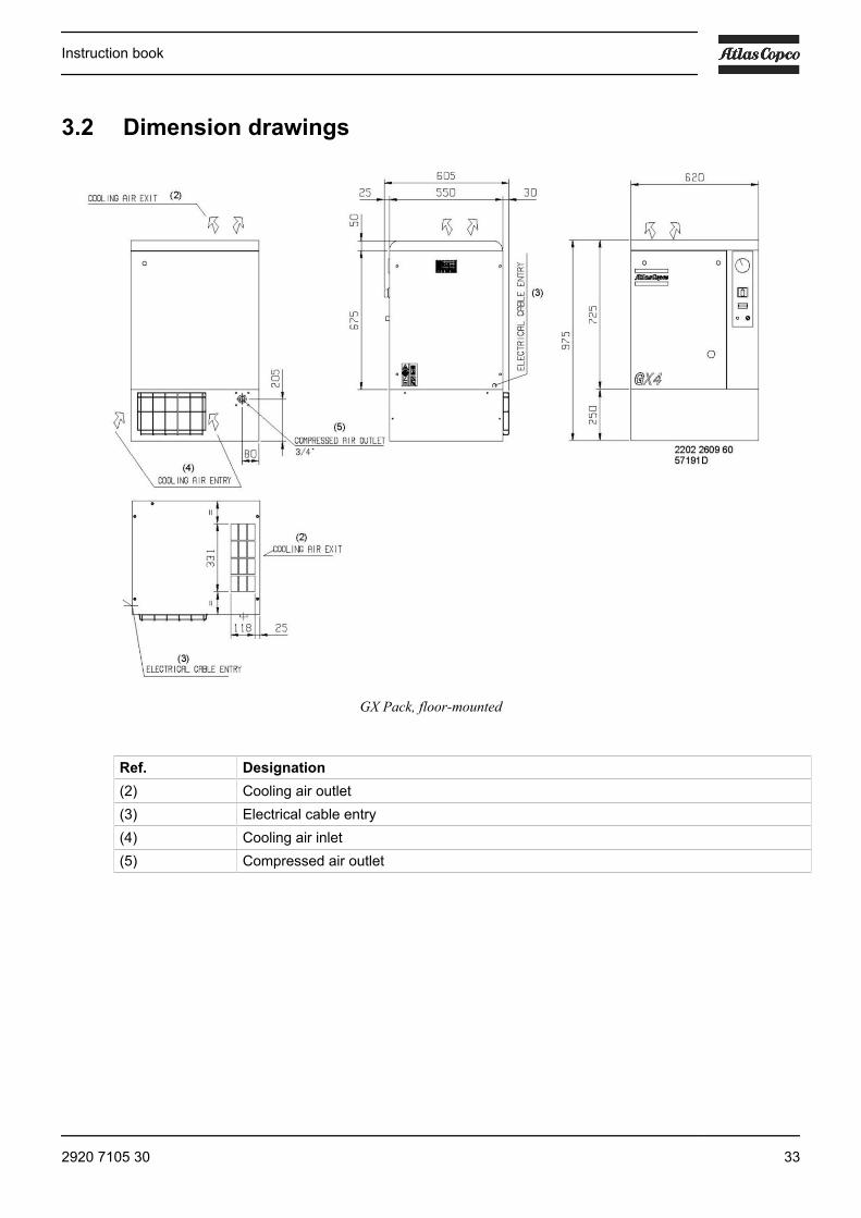
3.2 Dimension drawings
GX Pack, floor-mounted
Ref. Designation(2) Cooling air outlet(3) Electrical cable entry(4) Cooling air inlet(5) Compressed air outlet
Instruction book
2920 7105 30 33

GX 2 up to GX 5 Pack on 200 l receiver
(1) Cooling air outlet(2) Cooling air inlet(3) Compressed air outlet(4) Power supply cable(5) External box (only on GX 5 EP 230/1/60 and on all GX 7 EP)(6) Location of the centre of gravity (G)(7) Manual condensate drain
Instruction book
34 2920 7105 30

GX 7 EP Pack on 200l receiver
(2) Cooling air inlet
Instruction book
2920 7105 30 35
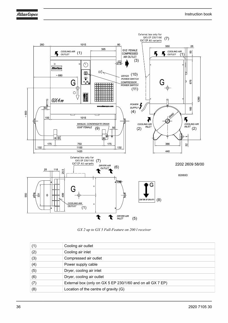
GX 2 up to GX 5 Full-Feature on 200 l receiver
(1) Cooling air outlet(2) Cooling air inlet(3) Compressed air outlet(4) Power supply cable(5) Dryer, cooling air inlet(6) Dryer, cooling air outlet(7) External box (only on GX 5 EP 230/1/60 and on all GX 7 EP)(8) Location of the centre of gravity (G)
Instruction book
36 2920 7105 30

(9) Manual condensate drain(10) Power switch, dryer(11) Power switch, compressor
GX 7 Full-Feature on 200 l receiver
(1) Power supply cable, dryer(2) Power supply cable, compressor(3) Cooling air inlet
3.3 Electrical connectionsAlways disconnect the power supply before working on the electrical circuit!
Instruction book
2920 7105 30 37
General instructions
Step Action1 Ensure that the supply voltage matches the voltage on the data plate.2 Install an isolating switch near the compressor.
For Full-Feature compressors: fit an isolating switch near the dryer.3 Fit fuses in the incoming wiring. Check the condition of all incoming wiring and make
connections. See Electrical diagrams.
3.4 Pictographs
Instruction book
38 2920 7105 30

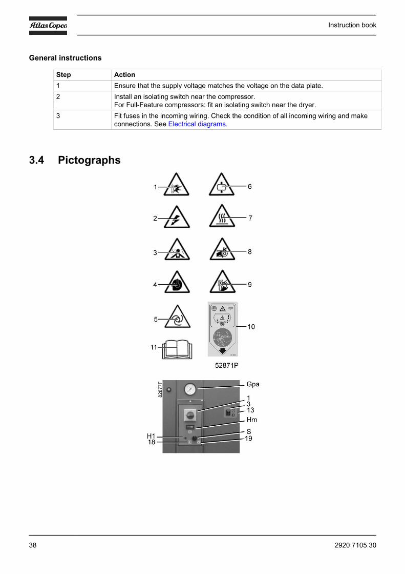
Ref. Description1 Warning: possible air/fluid discharge2 Warning: voltage3 Warning: air must not be inhaled4 Warning: wear ear protectors5 Warning: machine may start automatically6 Warning: pressure7 Warning: hot parts8 Warning: moving parts9 Warning: rotating fan10 Drain condensate daily11 Read the instruction manual13 Hour meter16 Read instruction manual before carrying out maintenance or repair work17 Lightly oil gasket of oil filter, screw filter on and tighten by hand18 Start19 • GX 2 EP up to GX 5 EP: Stop
• GX 7 EP: unload
Instruction book
2920 7105 30 39
4 Operating instructions
4.1 Initial start-up
Safety
The operator must apply all relevant Safety precautions.
General preparation
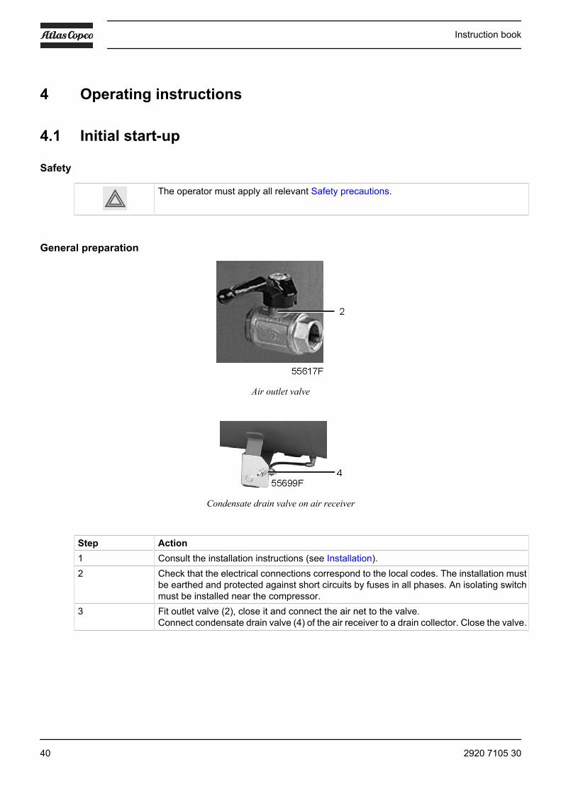
Air outlet valve
Condensate drain valve on air receiver
Step Action1 Consult the installation instructions (see Installation).2 Check that the electrical connections correspond to the local codes. The installation must
be earthed and protected against short circuits by fuses in all phases. An isolating switchmust be installed near the compressor.
3 Fit outlet valve (2), close it and connect the air net to the valve.Connect condensate drain valve (4) of the air receiver to a drain collector. Close the valve.
Instruction book
40 2920 7105 30

Oil system
Oil level sight-glass, GX
Step ActionIf more than 3 months have passed between assembly and installation, be sure tolubricate the compressor before starting up:• Remove the front panel.• Unscrew the fixing bolts in the top and remove the panel.• Unscrew the cover of the air filter (AF) and remove the filter element.• Open valve (7) and drain approx. 0.2 l (0.05 US gal / 0.04 Imp gal) of oil into a clean
receptacle. Carefully pour this oil through the filter housing into the compressorelement.
• Fit the air filter and screw on the filter cover.• Refit the top and front panels.
Check the oil level.The oil level sight-glass (SG) must be above the minimum level. If the oil level is below theminimum level, top up to the middle. Do not overfill. Always use the same type of oil.
Instruction book
2920 7105 30 41
Start-up
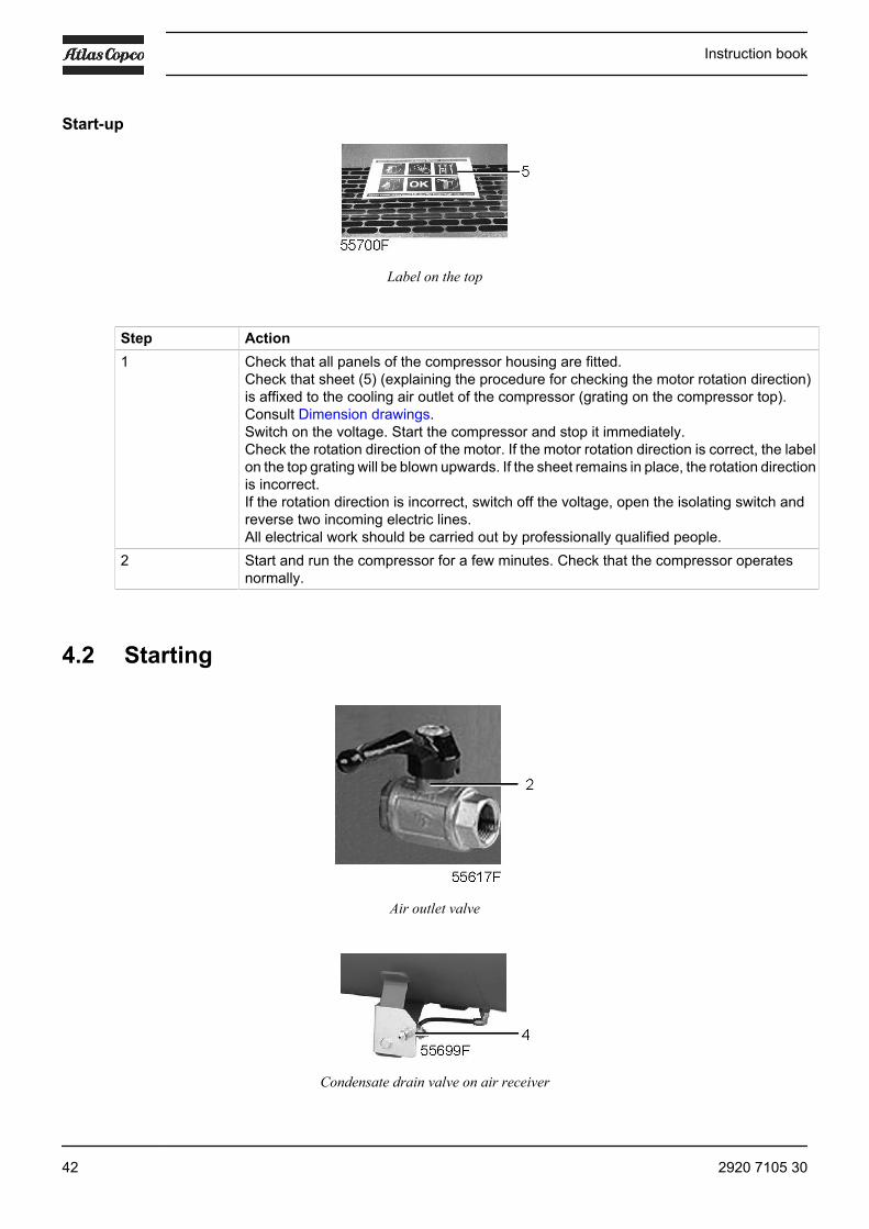
Label on the top
Step Action1 Check that all panels of the compressor housing are fitted.
Check that sheet (5) (explaining the procedure for checking the motor rotation direction)is affixed to the cooling air outlet of the compressor (grating on the compressor top).Consult Dimension drawings.Switch on the voltage. Start the compressor and stop it immediately.Check the rotation direction of the motor. If the motor rotation direction is correct, the labelon the top grating will be blown upwards. If the sheet remains in place, the rotation directionis incorrect.If the rotation direction is incorrect, switch off the voltage, open the isolating switch andreverse two incoming electric lines.All electrical work should be carried out by professionally qualified people.
2 Start and run the compressor for a few minutes. Check that the compressor operatesnormally.
4.2 Starting
Air outlet valve
Condensate drain valve on air receiver
Instruction book
42 2920 7105 30

Starting the air dyer
Dryer on/off switch
Switch on the voltage to the dryer and start it by moving switch (3) to position I.
• Switch on the dryer before starting the compressor.• The dryer must remain switched on when the compressor is operating to ensure that
the air piping remains condensate-free.• If the dryer is switched off, wait at least 5 minutes before restarting the dryer; this allows
for balancing of the internal pressure in the dryer.
Timer drain (rear side of the dryer)
Instruction book
2920 7105 30 43

Starting the compressor
Step Action1 Check the oil level sight glass (SG). The oil level should be in the middle. If it is below the
minimum level, top up to the middle. Do not overfill.2 Switch on the voltage by turning switch (1) to position I3 Open air outlet valve (2).4 Start the unit by moving selector switch (S) to position I5 Regularly check the working pressure (Gpa).6 On Full-Feature compressors, regularly check that condensate is drained during operation.
4.3 Stopping
Air outlet valve
Instruction book
44 2920 7105 30
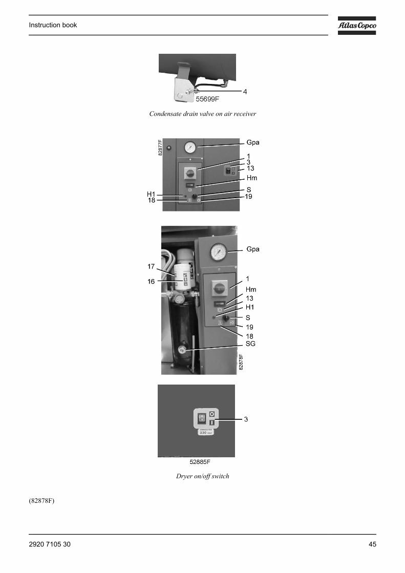
Condensate drain valve on air receiver
Dryer on/off switch
(82878F)
Instruction book
2920 7105 30 45

Step Action1 On Full-Feature units: move switch (3) of the dryer to position 0.
GX 2 EP to GX 5 EP:• Move start/stop switch (S) to position 0.• Turn off main switch (1)
GX 7 EP:• Move selector switch (S) to unload position.• Wait at least 30 seconds and turn off mains switch (1)
2 Close air outlet valve (2) and switch off the voltage to the compressor.On Full-Feature units: switch off the voltage to the dryer.
3 Open condensate drain valve (4) of the air receiver for a few seconds to drain anycondensate and then close the valve.The air dryer and the air receiver remain under pressure.The integrated filter (if installed) remains pressurised.If maintenance or repair work is necessary, consult the Problem solving section for allrelevant safety precautions.
4.4 Taking out of operation
Air outlet valve
Oil filler plug
This procedure should be carried out at the end of the compressor’s service life.
Step Action1 Stop the compressor and close the air outlet valve (2).
Instruction book
46 2920 7105 30

Step Action2 Switch off the voltage and disconnect the compressor from the mains.3 Depressurise the compressor by opening plug (3) one turn.
Open condensate drain valve (4) of the air receiver.4 Shut off and depressurise the part of the air net which is connected to the outlet valve.
Disconnect the compressor from the air net.5 Drain the oil and condensate circuits.6 Disconnect the compressor condensate outlet and valve from the condensate net.
Instruction book
2920 7105 30 47

5 Maintenance
5.1 Preventive maintenance schedule
Warning
Before carrying out any maintenance, repair work or adjustments, proceed asfollows:• Stop the compressor.• Switch off the voltage and open the isolating switch.• Close the air outlet valve and open the manual condensate drain valves.• Depressurise the compressor.
For detailed instructions, see the next sections.The operator must apply all relevant Safety precautions.
Warranty-Product Liability
Use only authorised parts. Any damage or malfunction caused by the use of unauthorised parts is not coveredby Warranty or Product Liability.
General
When servicing, replace all removed gaskets, O-rings and washers.
Intervals
Carry out maintenance at the interval which comes first. The local Atlas Copco Customer Centre may overrulethe maintenance schedule, especially the service intervals, depending on the environmental and workingconditions of the compressor.
The "longer interval" checks must also include the "shorter interval" checks.
Preventive maintenance schedule
Period (1) Running hours(1)
Action
Daily -- After stopping, drain the condensate from the air receiver .Check the oil level.
Monthly 50 For Full-Feature versions: check that condensate from the dryer isdraining automatically.
“ For Floor-mounted versions: inspect the prefilter at the rear side of thecompressor. Clean if necessary.
3-monthly 500 (2) Inspect the air filter. Clean if necessary.“ 500 Check the belt tension.“ “ For compressors with PDX filter: check the service indicator, replace
the filter if necessary.3-monthly 1000 (2) Inspect the oil cooler; clean if necessary.
Instruction book
48 2920 7105 30
Period (1) Running hours(1)
Action
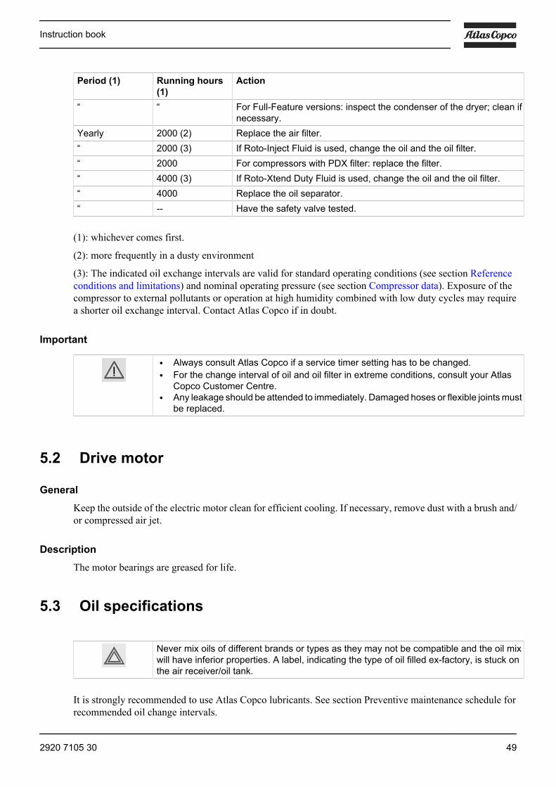
“ “ For Full-Feature versions: inspect the condenser of the dryer; clean ifnecessary.
Yearly 2000 (2) Replace the air filter.“ 2000 (3) If Roto-Inject Fluid is used, change the oil and the oil filter.“ 2000 For compressors with PDX filter: replace the filter.“ 4000 (3) If Roto-Xtend Duty Fluid is used, change the oil and the oil filter.“ 4000 Replace the oil separator.“ -- Have the safety valve tested.
(1): whichever comes first.
(2): more frequently in a dusty environment
(3): The indicated oil exchange intervals are valid for standard operating conditions (see section Referenceconditions and limitations) and nominal operating pressure (see section Compressor data). Exposure of thecompressor to external pollutants or operation at high humidity combined with low duty cycles may requirea shorter oil exchange interval. Contact Atlas Copco if in doubt.
Important
• Always consult Atlas Copco if a service timer setting has to be changed.• For the change interval of oil and oil filter in extreme conditions, consult your Atlas
Copco Customer Centre.• Any leakage should be attended to immediately. Damaged hoses or flexible joints must
be replaced.
5.2 Drive motor
General
Keep the outside of the electric motor clean for efficient cooling. If necessary, remove dust with a brush and/or compressed air jet.
Description
The motor bearings are greased for life.
5.3 Oil specifications
Never mix oils of different brands or types as they may not be compatible and the oil mixwill have inferior properties. A label, indicating the type of oil filled ex-factory, is stuck onthe air receiver/oil tank.
It is strongly recommended to use Atlas Copco lubricants. See section Preventive maintenance schedule forrecommended oil change intervals.
Instruction book
2920 7105 30 49

For part numbers, consult the Spare Parts List.
Roto-Inject Fluid
Atlas Copco's Roto-Inject Fluid is a specially developed lubricant for use in single stage oil-injected screwcompressors. Its specific composition keeps the compressor in excellent condition. Roto-Inject Fluid can beused for compressors operating at ambient temperatures between 0 ˚C (32 ˚F) and 40 ˚C (104 ˚F). If thecompressor is regularly operating in ambient temperatures between 40 °C and 46 °C (115 °F), oil lifetime isreduced significantly. In such case it is recommended to use Roto-Xtend Duty Fluid.
Roto-Xtend Duty Fluid
Atlas Copco's Roto-Xtend Duty Fluid is a high quality synthetic lubricant for oil-injected screw compressorswhich keeps the compressor in excellent condition. Because of its excellent oxidation stability, Roto-XtendDuty Fluid can be used for compressors operating at ambient temperatures between 0 ˚C (32 ˚F) and 46 ˚C(115 ˚F).
Roto-Foodgrade Fluid
Special oil, delivered as an option.
Atlas Copco's Roto-Foodgrade Fluid is a unique high quality synthetic lubricant, specially created for oil-injected screw compressors providing air for the food industry. This lubricant keeps the compressor inexcellent condition. Roto-Foodgrade Fluid can be used for compressors operating at ambient temperaturesbetween 0 ˚C (32 ˚F) and 40 ˚C (104 ˚F).
5.4 Oil, filter and separator change
Important
Never mix oils of different brands or types. A label, indicating the type of oil filled ex-factory,is stuck on the air receiver/oil tank.Always drain the compressor oil at all drain points. Used oil left in the compressor canshorten the lifetime of the new oil.If the compressor is exposed to external pollutants, is being used at high temperatures (oiltemperature above 90˚C / 194˚F) or is being used under severe conditions, it is advisableto change the oil more frequently. Consult Atlas Copco.
Instruction book
50 2920 7105 30
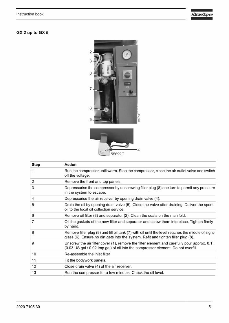
GX 2 up to GX 5
Step Action1 Run the compressor until warm. Stop the compressor, close the air outlet valve and switch
off the voltage.2 Remove the front and top panels.3 Depressurise the compressor by unscrewing filler plug (8) one turn to permit any pressure
in the system to escape.4 Depressurise the air receiver by opening drain valve (4).5 Drain the oil by opening drain valve (5). Close the valve after draining. Deliver the spent
oil to the local oil collection service.6 Remove oil filter (3) and separator (2). Clean the seats on the manifold.7 Oil the gaskets of the new filter and separator and screw them into place. Tighten firmly
by hand.8 Remove filler plug (8) and fill oil tank (7) with oil until the level reaches the middle of sight-
glass (6). Ensure no dirt gets into the system. Refit and tighten filler plug (8).9 Unscrew the air filter cover (1), remove the filter element and carefully pour approx. 0.1 l
(0.03 US gal / 0.02 Imp gal) of oil into the compressor element. Do not overfill.10 Re-assemble the inlet filter11 Fit the bodywork panels.12 Close drain valve (4) of the air receiver.13 Run the compressor for a few minutes. Check the oil level.
Instruction book
2920 7105 30 51

5.5 Storage after installation
If the compressor is stored without running from time to time, consult Atlas Copco as protective measuresmay be necessary.
5.6 Service kits
Service kits
For overhauling and for preventive maintenance, a wide range of service kits is available. Service kits compriseall parts required for servicing the component and offer the benefits of genuine Atlas Copco parts whilekeeping the maintenance budget low.
Also a full range of extensively tested lubricants, suitable for your specific needs is available to keep thecompressor in excellent condition.
Consult the Spare Parts List for part numbers.
Instruction book
52 2920 7105 30
6 Adjustments and servicing procedures
6.1 Air filter
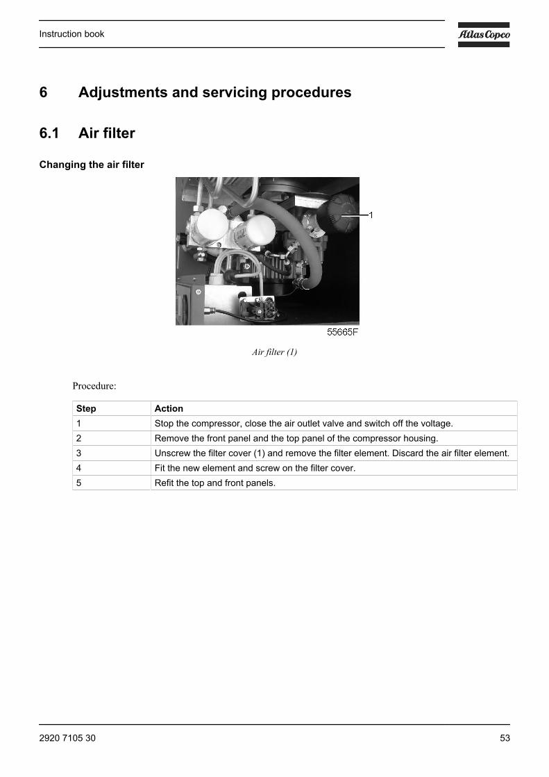
Changing the air filter
Air filter (1)
Procedure:
Step Action1 Stop the compressor, close the air outlet valve and switch off the voltage.2 Remove the front panel and the top panel of the compressor housing.3 Unscrew the filter cover (1) and remove the filter element. Discard the air filter element.4 Fit the new element and screw on the filter cover.5 Refit the top and front panels.
Instruction book
2920 7105 30 53
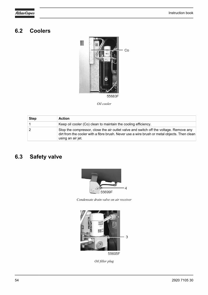
6.2 Coolers
Oil cooler
Step Action1 Keep oil cooler (Co) clean to maintain the cooling efficiency.2 Stop the compressor, close the air outlet valve and switch off the voltage. Remove any
dirt from the cooler with a fibre brush. Never use a wire brush or metal objects. Then cleanusing an air jet.
6.3 Safety valve
Condensate drain valve on air receiver
Oil filler plug
Instruction book
54 2920 7105 30

Testing
The valve can be tested on a separate compressed air line.
Before removing the valve, stop the compressor (see section Stopping).
On a Full-Feature unit also stop the dryer.
Close the air outlet valve, switch off the voltage, open drain valves (4) (if applicable) and unscrew filler plug(3) one turn to permit any pressure in the system to escape.
If the valve does not open at the set pressure stamped on the valve, replace the valve.No adjustments are allowed. Never run the compressor without a safety valve.
6.4 Belt set exchange and tensioning
Read the warning in the Preventive maintenance schedule section.
Belt tensioning procedure
Step Action1 Stop the compressor, close the air outlet valve and switch off the voltage.
For Full-Feature versions: also stop the dryer.2 Remove the front panel of the compressor housing.3 Remove the side, back and top panels of the compressor housing.4 Loosen the 4 bolts (2) by one turn.5 Adjust the belt tension by turning tensioning nut (1).
Instruction book
2920 7105 30 55

Step Action6 The tension is correct when a force of 50 N (11.25 lbf) applied at the midpoint of the belt
causes a deflection of 6 mm (0.23 in).7 Retighten bolts (2).8 Refit the bodywork panels.
Belt replacement procedure
Step Action1 Stop the compressor, close the air outlet valve and switch off the voltage.
For Full-Feature versions: also stop the dryer.2 Remove the front panel of the compressor housing.3 Remove the side, back and top panels of the compressor housing.4 Loosen the 4 bolts (2) by one turn.5 Release the belt tension by loosening tensioning nut (1).6 Remove the fan cowl.7 Remove the belt via the fan cowl opening. Install the new belt via the same opening.8 Tension belt (3) as described above.9 Re-assemble the fan cowl.10 Refit the bodywork panels.11 Check the belt tension after 50 running hours.
Instruction book
56 2920 7105 30

7 Problem solving
Air outlet valve
Dryer on/off switch
GX Full-Feature
Instruction book
2920 7105 30 57

Attention
Use only authorised parts. Any damage or malfunction caused by the use of unauthorisedparts is not covered by Warranty or Product Liability.Apply all relevant Safety precautions during maintenance or repair.GX 2 EP to GX 5 EP:• Move start/stop switch (S) to position 0.• Turn off main switch (1)
GX 7 EP:• Move selector switch (S) to unload position.• Wait at least 30 seconds and turn off mains switch (1)
Move dryer on/off switch (6) to position 0.Wait until the compressor has stopped and switch off the voltage. See the Stoppingsection.Open the isolating switch to prevent an accidental start.Close air outlet valve (2) and depressurise the compressor by opening the oil filler plug (3)one turn.Open manual condensate drain valves (4 and/or 5).The air outlet valve (2) can be locked during maintenance or repair as follows:• Close the valve.• Remove the screw fixing the handle• Lift the handle and turn it until the slot of the handle fits over the blocking edge on the
valve body.• Fit the screw.
Faults and remedies
For all references given hereafter, see Air flow diagram, Initial start-up or Regulating system.
Compressor
Condition Fault Remedy1 The machine does not start No power Check power supply
Fuse (F1) blown Replace fuseThe main motor thermalprotection has tripped
Check and let motor cool down; toreset/restart, move compressor start/stop switch to 0, then to I
2 The machine does not start,high oil temperature lamp is on(temperature switch tripped)
Oil cooler is dirty Clean coolerAmbient temperature too high Improve ventilation in compressor
roomOil level too low Top up oil tank
3 The compressor does notreach working pressure
Blow-off solenoid valve (Y1)remains open
Check; replace valve if necessary
4 Excess oil consumption Oil separator (OS) clogged Replace oil separatorOil level too high Drain to correct level
Air dryer
Condition Fault Remedy1 No compressed air passes
through the dryerPipes are frozen inside Hot-gas by-pass valve
malfunctioning; consult Atlas Copco
Instruction book
58 2920 7105 30

Condition Fault Remedy2 Condensate in the piping Insufficient condensate drain Check the operation of timer (T)
The dryer is working outside itsrating
Check room temperature - airtemperature at dryer. Clean thecondenser and check operation of fan
3 The compressor head is veryhot (above 55˚C / 131˚F) -motor overload
The dryer is working outside itsrating
Check room temperature - airtemperature at dryer. Clean thecondenser and check operation of fan
Insufficient refrigerant in dryer Have system checked for leaks orrefilled
4 The motor hums and does notstart
Line voltage too low Check power supplyThe machine was switched offand on again too rapidly (notenough time for the pressureequalization)
Wait a few minutes before starting themachine again
Instruction book
2920 7105 30 59

8 Technical data
8.1 Readings on control panel
Pressure gauge
Hourmeter
The readings mentioned below are valid under the reference conditions (see Referenceconditions and limitations).
Ref. NameGpa Air outlet pressure
Reading: Modulates between preset unloading/stopping pressure and loading pressureHm Hour meter
Reading: Total running time
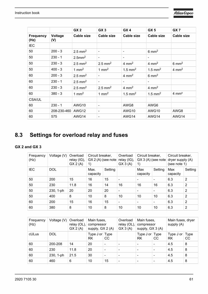
8.2 Electric cable size
Attention
Local regulations remain applicable if they are stricter than the values proposed below.The voltage drop must not exceed 5 % of the nominal voltage. It may be necessary to usecables of a larger size than those stated to comply with this requirement.
Instruction book
60 2920 7105 30
GX 2 GX 3 GX 4 GX 5 GX 7Frequency(Hz)
Voltage(V)
Cable size Cable size Cable size Cable size Cable size
IEC 50 200 - 3 2.5 mm2 - - 6 mm2
50 230 - 1 2.5mm2 - - -
50 230 - 3 2.5 mm2 2.5 mm2 4 mm2 4 mm2 6 mm2
50 400 - 3 1 mm2 1 mm2 1.5 mm2 1.5 mm2 4 mm2
60 200 - 3 2.5 mm2 - 4 mm2 6 mm2
60 230 - 1 2.5 mm2 - - -
60 230 - 3 2.5 mm2 2.5 mm2 4 mm2 4 mm2
60 380 - 3 1 mm2 1 mm2 1.5 mm2 1.5 mm2 4 mm²
CSA/UL 60 230 - 1 AWG10 - AWG8 AWG6 60 208-230-460 AWG12 - AWG10 AWG10 AWG860 575 AWG14 - AWG14 AWG14 AWG14
8.3 Settings for overload relay and fuses
GX 2 and GX 3
Frequency(Hz)
Voltage (V) Overloadrelay (IG),GX 2 (A)
Circuit breaker,GX 2 (A) (see note1)
Overloadrelay (IG),GX 3 (A)
Circuit breaker,GX 3 (A) (see note1)
Circuit breaker,dryer supply (A)(see note 1)
IEC DOL Max.capacity
Setting Maxcapacity
Setting Maxcapacity
Setting
50 200 15 16 15 - - - 6.3 250 230 11.8 16 14 16 16 16 6.3 250 230, 1-ph 20 20 20 - - - 6.3 250 400 8 10 8 10 10 10 6.3 260 200 15 16 15 - - - 6.3 260 380 8 10 8 10 10 10 6.3 2
Frequency(Hz)
Voltage (V) Overloadrelay (OL),GX 2 (A)
Main fuses,compressorsupply, GX 2 (A)
Overloadrelay (OL),GX 3 (A)
Main fuses,compressorsupply, GX 3 (A)
Main fuses, dryersupply (A)
cULus DOL Type J orRK
TypeCC
Type J orRK
TypeCC
Type J orRK
TypeCC
60 200-208 14 20 - - - - 4.5 860 230 11.8 20 - - - - 4.5 860 230, 1-ph 21.5 30 - - - - 4.5 860 460 6 10 15 - - - 4.5 8
Instruction book
2920 7105 30 61

60 575 5 8 12 - - - 4.5 8
(1): Motor circuit breaker with residual current device type D
GX 4 and GX 5
Frequency(Hz)
Voltage (V) Overloadrelay (IG),GX 4 (A)
Circuit breaker,GX 4 (A) (see note1)
Overloadrelay (IG),GX 5 (A)
Circuit breaker,GX 5 (A) (see note1)
Circuit breaker,dryer supply (A)(see note 1)
IEC DOL Max.capacity
Setting Maxcapacity
Setting Maxcapacity
Setting
50 230 19 20 20 - - - 6.3 250 400 11 16 11 - - - 6.3 260 200 19 20 19 - - - 6.3 260 380 11 16 11 13.5 16 13.5 6.3 2IEC Y-D 50 200 - - - 25 32 25 6.3 250 230 19 20 20 23.5 25 23.5 6.3 250 400 11 16 11 13.5 16 13.5 6.3 260 200 - - - 25 32 25 6.3 2
Frequency(Hz)
Voltage (V) Overloadrelay (OL),GX 4 (A)
Main fuses,compressorsupply, GX 4 (A)
Overloadrelay (OL),GX 5 (A)
Main fuses,compressorsupply, GX 5 (A)
Main fuses, dryersupply (A)
cULus DOL Type J orRK
TypeCC
Type J orRK
TypeCC
Type J orRK
TypeCC
60 200-208 21.2 30 - 24.7 40 - 4.5 860 230 18.2 30 - 22.5 40 - 4.5 860 230, 1-ph 30.8 60 - 41 60 - 4.5 860 460 9.1 12 25 11.4 15 25 4.5 860 575 7.5 10 15 9.5 12 20 4.5 8
(1): Motor circuit breaker with residual current device type D
GX 7
Frequency(Hz)
Voltage (V) Overloadrelay (IG),GX 7 (A)
Circuit breaker,GX 7 (A) (see note1)
Circuit breaker,dryer supply (A)(see note 1)
IEC Y-D Maxcapacity
Setting
50 230 19.1 32 31.5 6.3 250 400 11 20 18 6.3 260 380 11 20 19 6.3 2
Instruction book
62 2920 7105 30

Frequency(Hz)
Voltage (V) Overloadrelay (OL),GX 7 (A)
Main fuses,compressorsupply, GX 7 (A)
Main fuses, dryersupply (A)
cULus DOL Type J orRK
TypeCC
Type J orRK
TypeCC
60 200-208 36.3 50 - 4.5 860 230 34.4 45 - 4.5 860 460 16.9 25 25 4.5 860 575 13.8 20 15 4.5 8
(1): Motor circuit breaker with residual current device type D
8.4 Reference conditions and limitations
Reference conditions
Air inlet pressure (absolute) bar 1Air inlet pressure (absolute) psi 14.5Air inlet temperature ˚C 20Air inlet temperature ˚F 68Relative humidity % 0Working pressure bar(e) See Compressor dataWorking pressure psi See Compressor data
Limitations
Maximum working pressure bar(e) See Compressor dataMaximum working pressure psig See Compressor dataMinimum working pressure bar(e) 4Minimum working pressure psig 58Maximum air inlet temperature ˚C 46Maximum air inlet temperature ˚F 115Minimum ambient temperature ˚C 0Minimum ambient temperature ˚F 32
8.5 Compressor dataAll data specified below apply under reference conditions, see section Referenceconditions and limitations..
Instruction book
2920 7105 30 63

50 Hz 10 bar
Compressortype
GX 2 GX 3 GX 4 GX 5 GX 7
Frequency Hz 50 50 50 50 50Maximum(unloading)pressure, Pack
bar(e) 10 10 10 10 10
Maximum(unloading)pressure, Pack
psig 145 145 145 145 145
Maximum(unloading)pressure, Full-Feature
bar(e) 9.75 9.75 9.75 9.75 9.75
Maximum(unloading)pressure, Full-Feature
psig 141 141 141 141 141
Nominal workingpressure
bar(e) 9.5 9.5 9.5 9.5 9.5
Nominal workingpressure
psig 138 138 138 138 138
Pressure dropover dryer
bar(e) 0.15 0.15 0.15 0.15 0.25
Pressure dropover dryer
psig 2.18 2.18 2.18 2.18 3.62
Motor shaft speed rpm 2840 2840 2840 2840 2940Set-point,thermostatic valve
˚C 71 71 71 71 71
Set-point,thermostatic valve
˚F 160 160 160 160 160
Temperature of airleaving receiver(approx.), Pack
˚C 33 33 33 33 33
Temperature of airleaving receiver(approx.), Pack
˚F 91 91 91 91 91
Pressure dew-point, Full-Feature
˚C 3 3 3 3 3
Pressure dew-point, Full-Feature
˚F 37 37 37 37 37
Power input, Packat maximumworking pressure
kW 3.8 4.1 4.9 6.6 9.0
Power input, Packat maximumworking pressure
hp 5.1 5.5 6.57 8.85 12.27
Instruction book
64 2920 7105 30

Compressortype
GX 2 GX 3 GX 4 GX 5 GX 7
Power input, Full-Feature atmaximum workingpressure
kW 4.1 4.4 5.2 6.9 9.25
Power input, Full-Feature atmaximum workingpressure
hp 5.5 5.9 6.97 9.25 12.61
Powerconsumption,dryer at full load
kW 0.23 0.23 0.23 0.23 0.26
Powerconsumption,dryer at full load
hp 0.31 0.31 0.31 0.31 0.35
Powerconsumption,dryer at no load
kW 0.16 0.16 0.16 0.16 0.19
Powerconsumption,dryer at no load
hp 0.21 0.21 0.21 0.21 0.25
Refrigerant type R134a R134a R134a R134a R134aTotal amount,refrigerant
kg 0.17 0.17 0.17 0.17 0.29
Total amount,refrigerant
lb 0.37 0.37 0.37 0.37 0.64
Oil capacity l 2.5 2.5 2.5 2.5 2.5Oil capacity US gal 0.66 0.66 0.66 0.66 0.66Sound pressurelevel floor-mounted units(according to ISO2151 (2004))
dB(A) 61 61 62 64 66
60 Hz 10 bar
Compressor type GX 2 GX 4 GX 5 GX 7Frequency Hz 60 60 60 60Maximum (unloading) pressure,Pack
bar(e) 10 10 10 10
Maximum (unloading) pressure,Pack
psig 145 145 145 145
Maximum (unloading) pressure,Full-Feature
bar(e) 9.75 9.75 9.75 9.75
Maximum (unloading) pressure,Full-Feature
psig 141 141 141 141
Nominal working pressure bar(e) 9.5 9.5 9.5 9.5Nominal working pressure psig 138 138 138 138
Instruction book
2920 7105 30 65

Compressor type GX 2 GX 4 GX 5 GX 7Pressure drop over dryer bar(e) 0.15 0.15 0.15 0.25Pressure drop over dryer psig 2.18 2.18 2.18 3.62Motor shaft speed rpm 3495 3490 3495 3525Set-point, thermostatic valve ˚C 71 71 71 71Set-point, thermostatic valve ˚F 160 160 160 160Temperature of air leaving receiver(approx.), Pack
˚C 33 33 33 33
Temperature of air leaving receiver(approx.), Pack
˚F 91 91 91 91
Pressure dew-point, Full-Feature ˚C 3 3 3 3Pressure dew-point, Full-Feature ˚F 37 37 37 37Power input, Pack at maximumworking pressure
kW 3.7 4.7 6.3 9.0
Power input, Pack at maximumworking pressure
hp 4.96 6.3 8.45 12.27
Power input, Full-Feature atmaximum working pressure
kW 4 5 6.6 9.25
Power input, Full-Feature atmaximum working pressure
hp 5.36 6.71 8.85 12.61
Power consumption, dryer at fullload
kW 0.24 0.24 0.24 0.32
Power consumption, dryer at fullload
hp 0.33 0.33 0.33 0.44
Power consumption, dryer at noload
kW 0.17 0.17 0.17 0.22
Power consumption, dryer at noload
hp 0.23 0.23 0.23 0.30
Refrigerant type R134a R134a R134a R134aTotal amount, refrigerant kg 0.17 0.17 0.17 0.29Total amount, refrigerant lb 0.37 0.37 0.37 0.64Oil capacity l 2.5 2.5 2.5 2.5Oil capacity US gal 0.66 0.66 0.66 0.66Sound pressure level floor-mounted units (according to ISO2151 (2004))
dB(A) 61 62 64 66
Instruction book
66 2920 7105 30

9 Instructions for use
Oil separator vessel
1 The vessel can contain pressurised air. This can be potentially dangerous if the equipmentis misused.
2 This vessel must only be used as a compressed air/oil separator tank and must beoperated within the limits specified on the data plate.
3 No alterations must be made to this vessel by welding, drilling or other mechanical methodswithout the written permission of the manufacturer.
4 The pressure and temperature of this vessel must be clearly indicated.5 The safety valve must correspond with pressure surges of 1.1 times the maximum
allowable operating pressure. It should guarantee that the pressure will not permanentlyexceed the maximum allowable operating pressure of the vessel.
6 Use only oil as specified by the manufacturer.7 In case of misuse of the units (frequent operation with too low oil temperature or long
interval of shut down), a certain amount of condensate can gather in the oil separatorvessel which must be properly drained. To do so, disconnect the unit from the power line,wait till it is cooled down and depressurised and drain the water by the oil drain valve,positioned at the bottom side of the oil separator vessel.Local legislation may require an periodic inspection.
Air receiver (on tank-mounted units)
1 Corrosion must be prevented: depending on the conditions of use, condensate mayaccumulate inside the tank and must be drained every day. This may be donemanually by opening the drain valve, or by means of the automatic drain, if fitted to thetank. Nevertheless, a weekly check of correct functioning of the automatic valve is needed.This has to be done by opening the manual drain valve and check for condensate. Verifythat no rust obstructions affect the drain system.
2 Yearly service inspection of the air receiver is needed, as internal corrosion canreduce the steel wall thickness with the consequent risk of bursting. Local rules needto be respected, if applicable. The use of the air receiver is forbidden once the wallthickness reaches the minimum value as indicated in the service manual of the air receiver(part of the documentation delivered with the unit).
3 Lifetime of the air receiver mainly depends on the working environment. Installing thecompressor in a dirty and corrosive environment is not allowed, as this can reduce thevessel lifetime dramatically.
4 Do not anchor the vessel or attached components directly to the ground or fixed structures.Fit the pressure vessel with vibration dampers to avoid possible fatigue failure caused byvibration of the vessel during use.
5 Use the vessel within the pressure and temperature limits stated on the nameplate andthe testing report.
6 No alterations must be made to this vessel by welding, drilling or other mechanicalmethods.
Instruction book
2920 7105 30 67

10 Guidelines for inspection
Guidelines
On the Declaration of Conformity / Declaration by the Manufacturer, the harmonised and/or other standardsthat have been used for the design are shown and/or referred to.
The Declaration of Conformity / Declaration by the Manufacturer is part of the documentation that is suppliedwith this compressor.
Local legal requirements and/or use outside the limits and/or conditions as specified by the manufacturer mayrequire other inspection periods as mentioned below.
Instruction book
68 2920 7105 30

11 Pressure equipment directives
Components subject to 97/23/EC Pressure Equipment Directive
Components subject to 97/23/EC Pressure Equipment Directive greater than or equal to category II:
safety valves.
See the spare parts book for part numbers.
Overall rating
The compressors conform to PED smaller than category I.
Instruction book
2920 7105 30 69

12 Declaration of conformity
Typical example of a Declaration of Conformity document
(1): Contact address:
Atlas Copco Airpower n.v.
P.O. Box 100
B-2610 Wilrijk (Antwerp)
Belgium
Instruction book
70 2920 7105 30


No
292
0 71
05 3
0 / 2
012
- 03
- Prin
ted
in B
elgi
um
In order to be First in Mind—First in Choice® for all your qualitycompressed air needs, Atlas Copco delivers the products andservices that help to increase your business’ efficiency andprofitability.
Atlas Copco's pursuit of innovation never ceases, driven by ourneed for reliability and efficiency. Always working with you, we arecommitted to providing you the customized quality air solution thatis the driving force behind your business.
www.atlascopco.com