ATLAS COPCO COMPRESSED AIR MANUAL · ATLAS COPCO COMPRESSED AIR MANUAL 8th edition Compressed Air...
148
ATLAS COPCO COMPRESSED AIR MANUAL 8 th edition
Transcript of ATLAS COPCO COMPRESSED AIR MANUAL · ATLAS COPCO COMPRESSED AIR MANUAL 8th edition Compressed Air...

ATLAS COPCO COMPRESSED AIR MANUAL
8th editionCom
pressed Air M
anual 8th edition
www.atlascopco.comBelgium, 2015, 9780 0380 11
CAM_cover_English_2014.indd 1 13/04/15 14:54


COMPRESSED AIR MANUAL
8th edition
CAM_edition8_2014.indd 1 13/04/15 14:49

This Manual is published by:Atlas Copco Airpower NVBoomsesteenweg 957B-2610 WilrijkBelgium
Reproduction of the contents of this publication, fully or in part, is forbidden in accordance with copyright laws without prior written permission from Atlas Copco Airpower NV. This applies to any form of reproduction through printing, dupli-cation, photocopying, recording, etc.
During the production of this material we have gratefully received pictures and contributions from our customers and suppliers, of which we would especially like to name: ABB, Siemens, Vattenfall and AGA.
Atlas Copco Airpower NV
ISBN: 9789081535809© Atlas Copco Airpower NV, Belgium, 2015
CAM_edition8_2014.indd 2 13/04/15 14:49

WELCOME!
Welcome to the universe of compressed air! This manual offers a comprehensive guidance to anyone who is looking forward to further explore and get insights in compressed air technology. Whether you are a business person, manufacturing expert, scientist, university student or technical consultant, we believe that the knowledge collected in the manual will prove very useful to you. The compressed air manual is unique of its kind and has been widely used and hugely appreciated by many thousands of interested readers over the years. We are now proud to present the eight edition of the manual, several decades after the very first manual was introduced.
A lot of the information in the manual has been gathered around the world and over many years by a number of leading compressed air technology engineers from Atlas Copco. By sharing their knowledge with you, we want to ensure that efficiency gains can be realized faster and better throughout the many industries that depend on compressed air.
As we all know, there will always be room for new technical improvements and better ways of doing things. Our mission at Atlas Copco is to continuously deliver superior sustainable productivity through safer, cleaner, more energy-efficient cost effective compressed air solutions. To accomplish this, we depend on the voice of our customers. We are very grateful for any suggestions or comments that you might have which can help to make this this manual even more complete.
I wish you interesting readings and much success with your compressed air applications.
Nico DelvauxPresident of Compressor TechniqueAtlas Copco
We welcome your [email protected]
CAM_edition8_2014.indd 3 13/04/15 14:49

1 THEORY
1.1 PHYSICS 10 1.1.1 The structure of matter 10
1.1.2 The molecule and the differend states
of matter 10
1.2 PHYSICAL UNITS 11 1.2.1 Pressure 11
1.2.2 Temperature 11
1.2.3 Thermal capacity 11
1.2.4 Work 13
1.2.5 Power 13
1.2.6 Volume rate of flow 13
1.3 THERMODYNAMICS 13 1.3.1 Main principles 13
1.3.2 Gas laws 14
1.3.3 Heat transfer 14
1.3.4 Changes in state 16
1.3.4.1 Isochoric process 16 1.3.4.2 Isobaric process 16 1.3.4.3 Isothermal process 17 1.3.4.4 Isentropic process 17 1.3.4.5 Polytropic process 17
1.3.5 Gas flow through a nozzle 18
1.3.6 Flow through pipes 18
1.3.7 Throttling 18
1.4 AIR 19 1.4.1 Air in general 19
1.4.2 Moist air 19
1.5 TYPES OF COMPRESSORS 20 1.5.1 Two basic principles 20
1.5.2 Positive displacement compressors 20
1.5.3 The compressor diagram for
displacement compressors 20
1.5.4 Dynamic compressors 22
1.5.5 Compression in several stages 23
1.5.6 Comparison: turbocompressor and
positive displacement 23
1.6 ELECTRICITY 24 1.6.1 Basic terminology and definitions 24
1.6.2 Ohm’s law for alternating current 24
1.6.3 Three-phase system 25
1.6.4 Power 25
1.6.5 The electric motor 27
1.6.5.1 Rotation speed 27
1.6.5.2 Efficiency 27 1.6.5.3 Insulation class 27 1.6.5.4 Protection classes 27 1.6.5.5 Cooling methods 27 1.6.5.6 Installation method 28 1.6.5.7 Star (Y) and delta (∆) connections 28 1.6.5.8 Torque 29
2 COMPRESSORS AND AUXILIARY EQUIPMENT
2.1 DISPLACEMENT COMPRESSORS 32 2.1.1 Displacement compressors 32
2.1.2 Piston compressors 32
2.1.3 Oil-free piston compressors 32
2.1.4 Diaphragm compressor 34
2.1.5 Twin screw compressors 34
2.1.5.1 Oil-free screw compressors 34 2.1.5.2 Liquid-injected screw compressors 37
2.1.6 Tooth compressors 37
2.1.7 Scroll compressors 38
2.1.8 Vane compressors 40
2.1.9 Roots blowers 40
2.2 DYNAMIC COMPRESSORS 41 2.2.1 Dynamic compressors in general 41
2.2.2 Centrifugal compressors 41
2.2.3 Axial compressors 43
2.3 OTHER COMPRESSORS 43 2.3.1 Vacuum pumps 43
2.3.2 Booster compressors 43
2.3.3 Pressure intensifiers 44
2.4 TREATMENT OF COMPRESSED AIR 44 2.4.1 Drying compressed air 44
2.4.1.1 After-cooler 45 2.4.1.2 Refrigerant dryer 46 2.4.1.3 Over-compression 47
2.4.1.4 Absorption drying 47 2.4.1.5 Adsorption drying 47 2.4.1.6 Membrane dryers 50
2.4.2 Filters 50
2.5 CONTROL AND REGULATION SYSTEMS 52 2.5.1 Regulation in general 52
2.5.2 Regulation principles for displacement
compressors 53
2.5.2.1 Pressure relief 53
2.5.2.2 Bypass 54
CAM_edition8_2014.indd 4 13/04/15 14:49

2.5.2.3 Throttling the inlet 54
2.5.2.4 Pressure relief with throttled inlet 54
2.5.2.5 Start/stop 54
2.5.2.6 Speed regulation 54
2.5.2.7 Variable discharge port 55
2.5.2.8 Suction valve unloading 55
2.5.2.9 Load–unload–stop 55
2.5.3 Regulation principles for dynamic
compressors 56
2.5.3.1 Inlet regulation 56 2.5.3.2 Outlet regulation 56 2.5.3.3 Load–unload–stop 56 2.5.3.4 Speed regulation 56
2.5.4 Control and monitoring 57
2.5.4.1 General 57 2.5.4.2 Load–unload–stop 57 2.5.4.3 Speed control 58
2.5.5 Data monitoring 58
2.5.5.1 Temperature measurement 58 2.5.5.2 Pressure measurement 58 2.5.5.3 Monitoring 59
2.5.6 Comprehensive control system 60
2.5.6.1 Start sequence selector 60
2.5.7 Central control 61
2.5.8 Remote monitoring 61
2.6 MOBILE COMPRESSORS 63 2.6.1 General 63
2.6.2 Noise level and exhaust emissions 63
2.6.3 Operational flexibility 64
3 DIMENSIONING AND SERVICING COMPRESSOR INSTALLATIONS
3.1 DIMENSIONING COMPRESSOR
INSTALLATIONS 66 3.1.1 General 66
3.1.1.1 Calculating the working pressure 66 3.1.1.2 Calculating the air requirement 67 3.1.1.3 Measuring the air requirement 68
3.1.2 Centralization or decentralization 69
3.1.2.1 General 69 3.1.2.2 Centralized compressor installations 69 3.1.2.3 Decentralized compressor installations 69
3.1.3 Dimensioning at high altitude 69
3.1.3.1 General 69 3.1.3.2 The effect on a compressor 70
3.1.3.3 Power source 71 3.1.3.3.1 Dimensioning electric motors 71 3.1.3.3.2 Dimensioning IC engines 71
3.2 AIR TREATMENT 72 3.2.1 General 72
3.2.2 Water vapor in compressed air 72
3.2.3 Oil in compressed air 73
3.2.4 Micro-organisms in compressed air 74
3.2.5 Filters 74
3.2.6 After-cooler 75
3.2.7 Water separator 75
3.2.8 Oil / water separation 75
3.2.9 Medical air 76
3.3 COOLING SYSTEM 77 3.3.1 Water-cooled compressors 77
3.3.1.1 General 77 3.3.1.2 Open system without circulating water 77 3.3.1.3 Open system with circulating water 77 3.3.1.4 Closed system 78
3.3.2 Air cooled compressors 78
3.4 ENERGY RECOVERY 79 3.4.1 General 79
3.4.2 Calculation of the recovery potential 81
3.4.3 Recovery methods 82
3.4.3.1 General 82 3.4.3.2 Air-cooled system 82 3.4.3.3 Water-cooled system 82
3.5 THE COMPRESSOR ROOM 84 3.5.1 General 84
3.5.2 Placement and design 85
3.5.3 Foundation 85
3.5.4 Intake air 85
3.5.5 Compressor room ventilation 86
3.6 COMPRESSED AIR DISTRIBUTION 89 3.6.1 General 89
3.6.1.1 Air receiver 89
3.6.2 Design of the compressed air network 90
3.6.3 Dimensioning the compressed air network 90
3.6.4 Flow measurement 93
3.7 ELECTRICAL INSTALLATION 94 3.7.1 General 94
3.7.2 Motors 94
3.7.3 Starting methods 94
CAM_edition8_2014.indd 5 13/04/15 14:49

3.7.4 Control voltage 95
3.7.5 Short-circuit protection 95
3.7.6 Cables 95
3.7.7 Phase compensation 96
3.8 SOUND 96 3.8.1 General 96
3.8.2 Absorption 97
3.8.3 Room Constant 97
3.8.4 Reverberation 97
3.8.5 Relationship between sound power
level and sound pressure level 98
3.8.6 Sound measurements 98
3.8.7 Interaction of several sound sources 99
3.8.8 Sound reduction 99
3.8.9 Noise within compressor installations 100
4 ECONOMY
4.1 COST 102 4.1.1 Compressed air production cost 102
4.1.1.1 General 102 4.1.1.2 Cost allocation 103
4.2 OPPORTUNITIES FOR SAVING 103 4.2.1 Power requirement 103
4.2.2 Working pressure 103
4.2.3 Air consumption 104
4.2.4 Regulation method 105
4.2.5 Air quality 106
4.2.6 Energy recovery 107
4.2.7 Maintenance 108
4.2.7.1 Maintenance planning 108 4.2.7.2 Auxiliary equipment 109
4.3 LIFE CYCLE COST 109 4.3.1 General 109
4.3.2 LCC calculation 110
5 CALCULATION EXAMPLE
5.1 EXAMPLE OF DIMENSIONING
COMPRESSED AIR INSTALLATIONS 114
5.2 INPUT DATA 114 5.2.1 Compressed Air Requirement 114
5.2.2 Ambient conditions for dimensioning 114
5.2.3 Additional specifications 114
5.3 COMPONENT SELECTION 115 5.3.1 Dimensioning the compressor 115
5.3.2 Final compressor selection 116
5.3.3 Dimensioning the air receiver volume 116
5.3.4 Dimensioning the dryer 116
5.3.5 Summary for continued calculation 117
5.3.6 Checking calculations 117
5.4 ADDITIONAL DIMENSIONING WORK 118 5.4.1 Condensation quantity calculation 118
5.4.2 Ventilation requirement in the
compressor room 118
5.5 SPECIAL CASE: HIGH ALTITUDE 119
5.6 SPECIAL CASE: INTERMITTENT OUTPUT 120
5.7 SPECIAL CASE: WATERBORNE ENERGY
RECOVERY 121 5.7.1 Assumption 121
5.7.2 Calculation of the water flow in
the energy recovery circuit 122
5.7.3 Energy balance across the
recovery heat exchanger 122
5.7.4 Summary 122
5.8 SPECIAL CASE: PRESSURE DROP IN THE
PIPING 123
6 APPENDICES
6.1 THE SI SYSTEM 126
6.2 DRAWING SYMBOLS 128
6.3 DIAGRAMS AND TABLES 130
6.4 COMPILATION OF APPLICABLE
STANDARDS AND REGULATIONS 1356.4.1 General 135
6.4.2 Standards 135
6.4.3 Compilation 135
6.4.3.1 Machinery safety 135 6.4.3.2 Pressure equipment safety 135 6.4.3.3 Environment 136 6.4.3.4 Electrical safety 136 6.4.3.5 Medical devices – general 136 6.4.3.6 Standardization 136 6.4.3.7 Specifications and testing 136
CAM_edition8_2014.indd 6 13/04/15 14:49
CHAPTER 1THEORY
CHAPTER 2COMPRESSORS AND AUXILIARY EQUIPMENT
CHAPTER 3DIMENSIONING AND SERVICING COMPRESSOR INSTALLATIONS
CHAPTER 4ECONOMY
CHAPTER 5CALCULATION EXAMPLE
CHAPTER 6APPENDICES
CAM_edition8_2014.indd 7 13/04/15 14:49

CAM_edition8_2014.indd 8 13/04/15 14:50

1 THEORY
CAM_edition8_2014.indd 9 13/04/15 14:50
10
1.1 PHYSICS
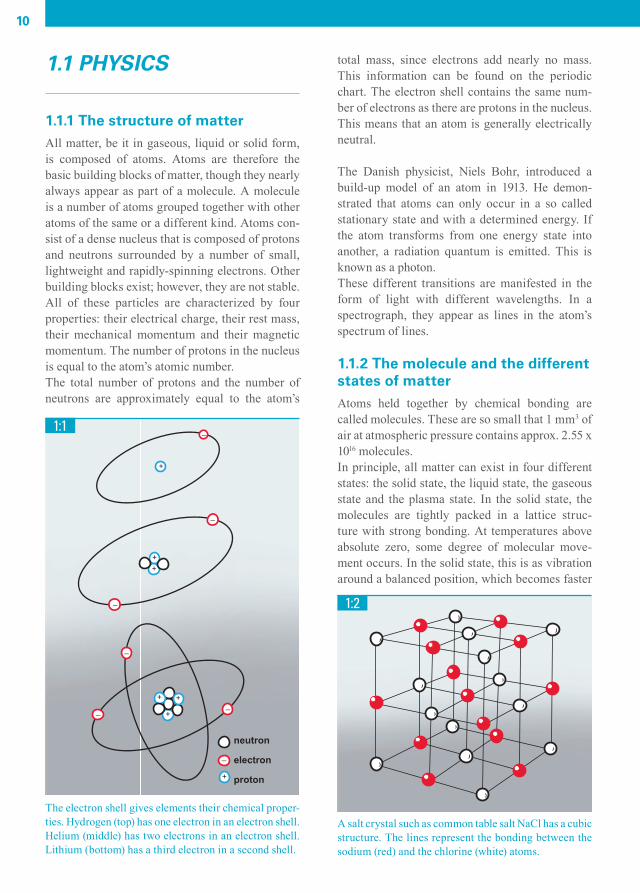
1.1.1 The structure of matterAll matter, be it in gaseous, liquid or solid form, is composed of atoms. Atoms are therefore the basic building blocks of matter, though they nearly always appear as part of a molecule. A molecule is a number of atoms grouped together with other atoms of the same or a different kind. Atoms con-sist of a dense nucleus that is composed of protons and neutrons surrounded by a number of small, lightweight and rapidly-spinning electrons. Other building blocks exist; however, they are not stable.All of these particles are characterized by four properties: their electrical charge, their rest mass, their mechanical momentum and their magnetic momentum. The number of protons in the nucleus is equal to the atom’s atomic number.The total number of protons and the number of neutrons are approximately equal to the atom’s
total mass, since electrons add nearly no mass. This information can be found on the periodic chart. The electron shell contains the same num-ber of electrons as there are protons in the nucleus. This means that an atom is generally electrically neutral.
The Danish physicist, Niels Bohr, introduced a build-up model of an atom in 1913. He demon-strated that atoms can only occur in a so called stationary state and with a determined energy. If the atom transforms from one energy state into another, a radiation quantum is emitted. This is known as a photon.These different transitions are manifested in the form of light with different wavelengths. In a spectrograph, they appear as lines in the atom’s spectrum of lines.
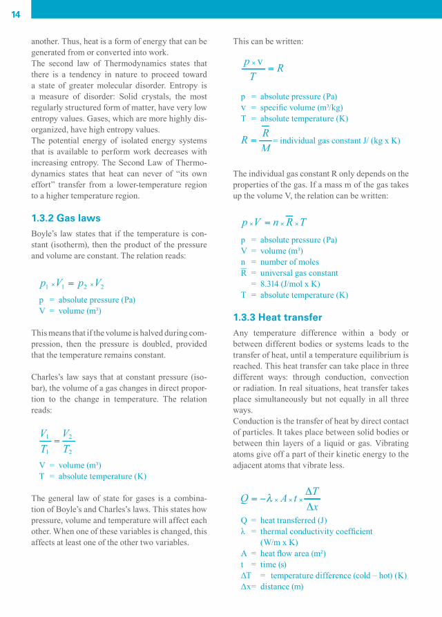
1.1.2 The molecule and the different states of matterAtoms held together by chemical bonding are called molecules. These are so small that 1 mm3 of air at atmospheric pressure contains approx. 2.55 x 10¹⁶ molecules.In principle, all matter can exist in four different states: the solid state, the liquid state, the gaseous state and the plasma state. In the solid state, the molecules are tightly packed in a lattice struc-ture with strong bonding. At temperatures above absolute zero, some degree of molecular move-ment occurs. In the solid state, this is as vibration around a balanced position, which becomes faster
1:1
The electron shell gives elements their chemical proper-ties. Hydrogen (top) has one electron in an electron shell. Helium (middle) has two electrons in an electron shell. Lithium (bottom) has a third electron in a second shell.
A salt crystal such as common table salt NaCl has a cubic structure. The lines represent the bonding between the sodium (red) and the chlorine (white) atoms.
+
_
+
+
__
_
_
_
+
+
_
+
+
neutron
electron
proton
1:2
CAM_edition8_2014.indd 10 13/04/15 14:50

11
as the temperature rises. When a substance in a solid state is heated so much that the movement of the molecules cannot be prevented by the rigid lat-tice pattern, they break loose, the substance melts and it is transformed into a liquid. If the liquid is heated further, the bonding of the molecules is entirely broken, and the liquid substance is trans-formed into a gaseous state, which expands in all directions and mixes with the other gases in the room. When gas molecules are cooled, they loose veloci-ty and bond to each other again to produce conden-sation. However, if the gas molecules are heatedfurther, they are broken down into individual sub-particles and form a plasma of electrons and atomic nuclei.
1.2 PHYSICAL UNITS
1.2.1 PressureThe force on a square centimeter area of an air col-umn, which runs from sea level to the edge of the atmosphere, is about 10.13 N. Therefore, the abso-lute atmospheric pressure at sea level is approx. 10.13 x 10⁴ N per square meter, which is equal to 10.13 x 10⁴ Pa (Pascal, the SI unit for pressure). Expressed in another frequently used unit:
1 bar = 1 x 10⁵ Pa. The higher you are above (or below) sea level, the lower (or higher) the atmo-spheric pressure.
1.2.2 TemperatureThe temperature of a gas is more diffi cult to defi ne clearly. Temperature is a measure of the kinetic energy in molecules. Molecules move more rapid-ly the higher the temperature, and movement com-pletely ceases at a temperature of absolute zero. The Kelvin (K) scale is based on this phenomenon, but otherwise is graduated in the same manner as the centigrade or Celsius (C) scale:
T = t + 273.2T = absolute temperature (K)t = centigrade temperature (C)
1.2.3 Thermal capacityHeat is a form of energy, represented by the kinetic energy of the disordered molecules of a substance. The thermal capacity (also called heat capacity) of an object refers to the quantity of heat required to produce a unit change of temperature (1K), and is expressed in J/K.The specifi c heat or specifi c thermal capacity of a substance is more commonly used, and refers to the quantity of heat required to produce a unit change of temperature (1K) in a unit mass of substance (1 kg).
By applying or removing thermal energy the physical state of a substance changes. This curve illustrates the effect for pure water.
1:3
super heating
evaporation at atmospheric pressure
(water + steam)
(water)
(ice)
ice melts
(steam)
0 1000 2000 3000 kJ/kgHeat added
Temperature°C
200
100
0-20
CAM_edition8_2014.indd 11 13/04/15 14:50

12
Specifi c heat is expressed in J/(kg x K). Similarly, the molar heat capacity is dimensioned J/(mol x K).
cp = specifi c heat at constant pressurecV = specifi c heat at constant volumeCp = molar specifi c heat at constant pressureCV = molar specifi c heat at constant volume
The specifi c heat at constant pressure is always greater than the specifi c heat at constant volume. The specifi c heat for a substance is not a constant, but rises, in general, as the temperature rises.For practical purposes, a mean value may be used. For liquids and solid substances cp ≈ cV ≈ c. To heat a mass fl ow ( ) from temperature t1 to t2 will then require:
P = heat power (W) = mass fl ow (kg/s)c = specifi c heat (J/kg x K)T = temperature (K)
Most pressure gauges register the difference between the pressure in a vessel and the local atmospheric pressure. There-fore to fi nd the absolute pressure the value of the local atmospheric pressure must be added.
1:4actual pressure
effective pressure(gauge pressure)bar (g) = bar (e)
vacuum bar (u)
absolutepressurebar (a)
localatmosphericpressure(barometicpressure)bar (a)
absolutepressurebar (a)
zero pressure (perfect vacuum)
variable level
normalatmosphericpressure (a)
This illustrates the relation between Celsius and Kelvin scales. For the Celsius scale 0° is set at the freezing point of water; for the Kelvin scale 0° is set at absolute zero.
1:5
water boils
water freezes
absolute zero
400373350
300273250
200
150
100
50
0-273-250
-200
-150
-100
-50
0
50
100
KCo
m
m
CAM_edition8_2014.indd 12 13/04/15 14:50

13
The explanation as to why cp is greater than cV is the expansion work that the gas at a constant pres-sure must perform. The ratio between cp and cV is called the isentropic exponent or adiabatic expo-nent, К, and is a function of the number of atoms in the molecules of the substance.
1.2.4 WorkMechanical work may be defined as the product of a force and the distance over which the force oper-ates on a body. Exactly as for heat, work is energy that is transferred from one body to another. The difference is that it is now a matter of force instead of temperature.An illustration of this is gas in a cylinder being compressed by a moving piston. Compression takes place as a result of a force moving the piston. Energy is thereby transferred from the piston to the enclosed gas. This energy transfer is work in the thermodynamic sense of the word. The result of work can have many forms, such as changes in the potential energy, the kinetic energy or the ther-mal energy.The mechanical work associated with changes in the volume of a gas mixture is one of the most important processes in engineering thermody-namics. The SI unit for work is the Joule: 1 J = 1 Nm = 1 Ws.
1.2.5 PowerPower is work performed per unit of time. It is a measure of how quickly work can be done. The SI unit for power is the Watt: 1 W = 1 J/s.For example, the power or energy flow to a drive shaft on a compressor is numerically similar to the heat emitted from the system plus the heat applied to the compressed gas.
1.2.6 Volume rate of flowThe volumetric flow rate of a system is a measure of the volume of fluid flowing per unit of time. It may be calculated as the product of the cross- sectional area of the flow and the average flow
velocity. The SI unit for volume rate of flow is m3/s.However, the unit liter/second (l/s) is also fre-quently used when referring to the volume rate of flow (also called the capacity) of a compressor. It is either stated as Normal liter/second (Nl/s) or as free air delivery (l/s). With Nl/s the air flow rate is recalculated to “the normal state”, i.e. conventionally chosen as 1.013 bar(a) and 0°C. The Normal unit Nl/s is primarily used when specifying a mass flow.For free air delivery (FAD) the compressor’s out-put flow rate is recalculated to a free air volume rate at the standard inlet condition (inlet pressure 1 bar(a) and inlet temperature 20°C). The relation between the two volume rates of flow is (note that the simplified formula below does not account for humidity):
qFAD = Free Air Delivery (l/s)qN = Normal volume rate of flow (Nl/s)TFAD = standard inlet temperature (20°C)TN = Normal reference temperature (0°C)pFAD = standard inlet pressure (1.00 bar(a))pN = Normal reference pressure (1.013 bar(a))
1.3 THERMODYNAMICS
1.3.1 Main principlesEnergy exists in various forms, such as thermal, physical, chemical, radiant (light etc.) and electri-cal energy. Thermodynamics is the study of ther-mal energy, i.e. of the ability to bring about change in a system or to do work.The first law of thermodynamics expresses the principle of conservation of energy. It says that energy can be neither created nor destroyed, and from this, it follows that the total energy in a closed system is always conserved, thereby remaining constant and merely changing from one form into
CAM_edition8_2014.indd 13 13/04/15 14:50
14
another. Thus, heat is a form of energy that can be generated from or converted into work. The second law of Thermodynamics states that there is a tendency in nature to proceed toward a state of greater molecular disorder. Entropy is a measure of disorder: Solid crystals, the most regularly structured form of matter, have very low entropy values. Gases, which are more highly dis-organized, have high entropy values. The potential energy of isolated energy systems that is available to perform work decreases with increasing entropy. The Second Law of Thermo-dynamics states that heat can never of “its own effort” transfer from a lower-temperature region to a higher temperature region.
1.3.2 Gas lawsBoyle’s law states that if the temperature is con-stant (isotherm), then the product of the pressure and volume are constant. The relation reads:
p = absolute pressure (Pa)V = volume (m³)
This means that if the volume is halved during com-pression, then the pressure is doubled, provided that the temperature remains constant.
Charles’s law says that at constant pressure (iso-bar), the volume of a gas changes in direct propor-tion to the change in temperature. The relation reads:
V = volume (m³)T = absolute temperature (K)
The general law of state for gases is a combina-tion of Boyle’s and Charles’s laws. This states how pressure, volume and temperature will affect each other. When one of these variables is changed, this affects at least one of the other two variables.
This can be written:
v
p = absolute pressure (Pa)v = specific volume (m³/kg)T = absolute temperature (K)
= individual gas constant J/ (kg x K)
The individual gas constant R only depends on the properties of the gas. If a mass m of the gas takes up the volume V, the relation can be written:
p = absolute pressure (Pa)V = volume (m³)n = number of moles R = universal gas constant = 8.314 (J/mol x K)T = absolute temperature (K)
1.3.3 Heat transferAny temperature difference within a body or between different bodies or systems leads to the transfer of heat, until a temperature equilibrium is reached. This heat transfer can take place in three different ways: through conduction, convection or radiation. In real situations, heat transfer takes place simultaneously but not equally in all three ways.Conduction is the transfer of heat by direct contact of particles. It takes place between solid bodies or between thin layers of a liquid or gas. Vibrating atoms give off a part of their kinetic energy to the adjacent atoms that vibrate less.
Q = heat transferred (J)λ = thermal conductivity coefficient (W/m x K)A = heat flow area (m²)t = time (s)ΔT = temperature difference (cold – hot) (K)Δx = distance (m)
CAM_edition8_2014.indd 14 13/04/15 14:50

15
Convection is the transfer of heat between a hot solid surface and the adjacent stationary or mov-ing fl uid (gas or liquid), enhanced by the mixing of one portion of the fl uid with the other. It can occur as free convection, by natural movement in a medium as a result of differences in density due to temperature differences. It can also occur as forced convection with fl uid movement caused by mechanical agents, for example a fan or a pump. Forced convection produces signifi cantly higher heat transfer as a result of higher mixing veloci-ties.
Q = heat transferred (J)h = heat transfer coeffi cient (W/m² x K)A = contact area (m²)t = time (s)ΔT = temperature difference (cold – hot) (K)
Radiation is the transfer of heat through empty space. All bodies with a temperature above 0°K emit heat by electro-magnetic radiation in all directions. When heat rays hit a body, some of the
energy is absorbed and transformed to heat up that body. The rays that are not absorbed pass through the body or are refl ected by it.
In real situations, heat transmission is the sum of the simultaneous heat transfer through conduction, convection and radiation.
Generally, the heat transmission relation below applies:
Q = total heat transmitted (J)k = total heat transfer coeffi cient (W/m² x K)A = area (m²)t = time (s)∆T = temperature difference (cold – hot) (K)
Heat transfer frequently occurs between two bodies that are separated by a wall. The total heat transfer coeffi cient “k” depends on the heat transfer coeffi -cient of both sides of the wall and on the coeffi cient of thermal conductivity for the wall itself.
This illustrates the temperature gradient in counter fl ow and in parallel fl ow heat exchangers.
1:6
CAM_edition8_2014.indd 15 13/04/15 14:50

16
For a clean, fl at wall the relation below applies:
α1 , α2 = heat transfer coeffi cient on each side of the wall (W/m² x K)d = thickness of the wall (m)λ = thermal conductivity for the wall (W/m x K)k = total heat transfer coeffi cient (W/m² x K)
The heat transmission in a heat exchanger is at each point a function of the prevailing temperature difference and of the total heat transfer coeffi cient. It requires the use of a logarithmic mean tempera-ture difference Өm instead of a linear arithmetic ΔT.
The logarithmic mean temperature difference is defi ned as the relationship between the tempera-ture differences at the heat exchanger’s two con-nection sides according to the expression:
Өm = logarithmic mean temperature difference (K)
1.3.4 Changes in stateChanges in state for a gas can be followed from one point to another in a p/V diagram. For real-life cases, three axes for the variables p, V and T are required. With a change in state, we are moved along a 3-dimensional curve on the surface in the p, V and T space. However, to simplify, we usually consider the pro-jection of the curve in one of the three planes. This is usually the p/V plane. Five different changes in state can be considered:- Isochoric process (constant volume), - Isobaric process (constant pressure), - Isothermal process (constant temperature),- Isentropic process (without heat exchange with
surroundings),- Polytropic process (complete heat exchange with
the surroundings). Isobaric change of state means that the volume changes, while the pressure is constant.
1:8
V
21
p
p
q12
V T1 1 V T2 2
= applied energy
1.3.4.1 Isochoric process
Heating a gas in an enclosed container is an exam-ple of the isochoric process at constant volume.
Q = quantity of heat (J)m = mass (kg)cV = specifi c heat at constant volume (J/kg x K)T = absolute temperature (K)
1.3.4.2 Isobaric process
Isochoric change of state means that the pressure chang-es, while the volume is constant.
1:7
1
2
q12
p
V
p T 2 2
p T1 1
V = V1 2
= applied energy
p
CAM_edition8_2014.indd 16 13/04/15 14:50

17
Heating a gas in a cylinder with a constant load on the piston is an example of the isobaric process at constant pressure.
Q = quantity of heat (J)m = mass (kg)cp = specifi c heat at constant pressure (J/kg x K)T = absolute temperature (K)
1.3.4.3 Isothermal process
1.3.4.4 Isentropic process
Isothermal change of state means that the pressure and volume are changed while the temperature remains con-stant.
When the entropy in a gas being compressed or expand-ed is constant, no heat exchange with the surroundings takes place. This change in state follows Poisson’s law.
1:9
1:10
p
p
V
12q = quality of heat led offp2
p1V1
2
1
V2
p
p
V
isentropic
1
p2
p1
VV
2
2 1
If a gas in a cylinder is compressed isothermally, a quantity of heat equal to the applied work must be gradually removed. This is unpractical, as such a slow process cannot occur.
Q = quantity of heat (J)m = mass (kg)R = individual gas constant (J/kg x K)T = absolute temperature (K)V = volume (m³)p = absolute pressure (Pa)
An isentropic process exists if a gas is compressed in a fully-insulated cylinder without any heat exchange with the surroundings. It may also exist if a gas is expanded through a nozzle so quickly that no heat exchange with the surroundings has time to occur.
p = absolute pressure (Pa)V = volume (m³)T = absolute temperature (K)κ = Cp / CV = isentropic exponent
1.3.4.5 Polytropic processThe isothermal process involves full heat exchange with the surroundings and the isotropic process involves no heat exchange whatsoever. In reality, all processes occur somewhere in between these extreme: the polytropic process. The relation for such a process is:
p = absolute pressure (Pa)V = volume (m³)n = 0 for isobaric processn = 1 for isothermal processn = κ for isentropic processn = ∞ for isochoric process
or
= constant
CAM_edition8_2014.indd 17 13/04/15 14:50

18
1.3.5 Gas fl ow through a nozzleThe gas fl ow through a nozzle depends on the pressure ratio on the respective sides of the nozzle. If the pressure after the nozzle is lowered, the fl ow increases. It only does so, however, until its pres-sure has reached half of the pressure before the nozzle. A further reduction of the pressure after the opening does not bring about an increase in fl ow.This is the critical pressure ratio and it is dependent on the isentropic exponent (κ) of the particular gas. The critical pressure ratio also occurs when the fl ow velocity is equal to the sonic velocity in the nozzle’s narrowest section.The fl ow becomes supercritical if the pressure after the nozzle is reduced further, below the criti-cal value. The relation for the fl ow through the nozzle is:
Q = mass fl ow (kg/s)α = nozzle coeffi cientψ = fl ow coeffi cientA = minimum area (m²)R = individual gas constant (J/kg x K)T1 = absolute temperature before nozzle (K)p1 = absolute pressure before nozzle (Pa)
1.3.6 Flow through pipesThe Reynolds number is a dimensionless ratio between inertia and friction in a fl owing medium. It is defi ned as:
D = characteristic dimension (e.g. the pipe diameter) (m)w = mean fl ow velocity (m/s)ρ = density of the fl owing medium (kg/m³)η = medium dynamic viscosity (Pa . s)
In principal, there are two types of fl ow in a pipe.With Re <2000 the viscous forces dominate in the medium and the fl ow becomes laminar. This means that different layers of the medium move
in relation to each other in the proper order. The velocity distribution across the laminar layers is usually parabolic shaped. With Re≥4000 the inertia forces dominate the behavior of the fl owing medium and the fl ow becomes turbulent, with particles moving random-ly across the fl ow. The velocity distribution across a layer with turbulent fl ow becomes diffuse.
In the critical area, between Re≤2000 and Re≥4000, the fl ow conditions are undetermined, either laminar, turbulent or a mixture of the both. The conditions are governed by factors such as the surface smoothness of the pipe or the presence of other disturbances. To start a fl ow in a pipe requires a specifi c pressure difference to overcome the friction in the pipe and the couplings. The amount of the pressure differ-ence depends on the diameter of the pipe, its length and form as well as the surface smoothness and Reynolds number.
1.3.7 ThrottlingWhen an ideal gas fl ows through a restrictor with a constant pressure before and after the restric-tor, the temperature remains constant. However, a pressure drop occurs across the restrictor, through the inner energy being transformed into kinetic energy. This is the reason for which the tempera-ture falls. For real gases, this temperature change becomes permanent, even though the energy con-tent of the gas remains constant. This is called the Joule-Thomson effect. The temperature change is equal to the pressure change across the throttling multiplied by the Joule-Thomson coeffi cient.
When an ideal gas fl ows through a small opening between two large containers, the energy becomes constant and no heat exchange takes place. However, a pressure drop occurs with the passage through the restrictor.
1:11
W2
CAM_edition8_2014.indd 18 13/04/15 14:50

19
If the fl owing medium has a suffi ciently low tem-perature (≤+329°C for air), a temperature drop occurs with the throttling across the restrictor, but if the fl ow medium is hotter, a temperature increase occurs instead. This condition is used in several technical applications, for example, in refrigera-tion technology and in separation of gases.
1.4 AIR
1.4.1 Air in generalAir is a colorless, odorless and tasteless gas mix-ture. It is a mixture of many gases, but is primar-ily composed of oxygen (21%) and nitrogen (78%). This composition is relatively constant, from sea level up to an altitude of 25 kilometers.Air is not a pure chemical substance, but a mechan-ically-mixed substance. This is why it can be sepa-rated into its constituent elements, for example, by cooling.
1.4.2 Moist airAir can be considered a mixture of dry air and water vapor. Air that contains water vapor is called moist air, but the air’s humidity can vary within broad limits. Extremes are completely dry air and air saturated with moisture. The maximum water vapor pressure that air can hold increases with ris-ing temperatures. A maximum water vapor pres-sure corresponds to each temperature.Air usually does not contain so much water vapor that maximum pressure is reached. Relative vapor pressure (also known as relative humidity) is a state between the actual partial vapor pressure and the saturated pressure at the same temperature.The dew point is the temperature when air is satu-rated with water vapor. Thereafter, if the tempera-ture falls, the water condenses. Atmospheric dew point is the temperature at which water vapor starts to condense at atmospheric pressure. Pressure dew point is the equivalent temperature with increased pressure. The following relation applies:
p = total absolute pressure (Pa)ps = saturation pressure at actual temp. (Pa)φ = relative vapor pressureV = total volume of the moist air (m3)Ra = gas constant for dry air = 287 J/kg x KRv = gas constant for water vapor = 462 J/kg x Kma = mass of the dry air (kg)mv = mass of the water vapor (kg)T = absolute temperature of the moist air (K)
Air is a gas mixture that primarily consists of oxygen and nitrogen. Only approx. 1% is made up of other gases.
1:12
Others 1%
Nitrogen78%
Oxygen 21%
Atmospheric air is always more or less contami-nated with solid particles, for example, dust, sand, soot and salt crystals. The degree of contamination is higher in populated areas, and lower in the coun-tryside and at higher altitudes.
CAM_edition8_2014.indd 19 13/04/15 14:50

20
1.5 TYPES OF COMPRESSORS
1.5.1 Two basic principlesThere are two generic principles for the compres-sion of air (or gas): positive displacement compres-sion and dynamic compression. Positive displacement compressors include, for example, reciprocating (piston) compressors, orbital (scroll) compressors and different types of rotary compressors (screw, tooth, vane). In positive displacement compression, the air is drawn into one or more compression chambers, which are then closed from the inlet. Gradually the volume of each chamber decreases and the air is compressed internally. When the pressure has reached the designed build-in pressure ratio, a port or valve is opened and the air is discharged into the outlet system due to continued reduction of the compression chamber’s volume.In dynamic compression, air is drawn between the blades on a rapidly rotating compression impeller and accelerates to a high velocity. The gas is then discharged through a diffuser, where the kinetic energy is transformed into static pressure. Most dynamic compressors are turbocompressors with an axial or radial fl ow pattern. All are designed for large volume fl ow rates.
1.5.2 Positive displacement compressorsA bicycle pump is the simplest form of a positive displacement compressor, where air is drawn into a cylinder and is compressed by a moving piston. The piston compressor has the same operating principle and uses a piston whose forward and backward movement is accomplished by a con-necting rod and a rotating crankshaft. If only one side of the piston is used for compression this is called a single-acting compressor. If both the pis-ton’s top and undersides are used, the compressor is double acting.
The pressure ratio is the relationship between abso-lute pressure on the inlet and outlet sides. Accord-
Single stage, single acting piston compressor.
1:13
ingly, a machine that draws in air at atmospheric pressure (1 bar(a) and compresses it to 7 bar over-pressure works at a pressure ratio of (7 + 1)/1 = 8.
1.5.3 The compressor diagram for displacement compressorsFigure 1:15 illustrates the pressure-volume rela-tionship for a theoretical compressor and fi gure 1:16 illustrates a more realistic compressor dia-gram for a piston compressor. The stroke volume is the cylinder volume that the piston travels dur-ing the suction stage. The clearance volume is the volume just underneath the inlet and outlet valves and above the piston, which must remain at the piston’s top turning point for mechanical reasons.The difference between the stroke volume and the suction volume is due to the expansion of the air remaining in the clearance volume before suction can start. The difference between the theoretical p/V diagram and the actual diagram is due to the practical design of a compressor, e.g. a piston com-pressor. The valves are never completely sealed and there is always a degree of leakage between the piston skirt and the cylinder wall. In addition,
CAM_edition8_2014.indd 20 13/04/15 14:50

21
Most common compressor types, divided according to their working principles.
1:14
Ejector Radial Axial
Rotary
Dynamic DisplacementCompressors
Piston compressors
Single acting Double acting Labyrinth sealed Diaphragm
Single rotor Double rotor
Screw Tooth BlowerVane Liquid ring Scroll
CAM_edition8_2014.indd 21 13/04/15 14:50

22
the valves can not fully open and close without a minimal delay, which results in a pressure drop when the gas fl ows through the channels. The gas is also heated when fl owing into the cylinder as a consequence of this design.
Compression work with isothermalcompression:
Compression work with isentropic compression:
W = compression work (J)p1 = initial pressure (Pa)V1 = initial volume (m3)p2 = fi nal pressure (Pa)К = isentropic exponent: К ≈ 1,3 – 1,4
These relations show that more work is required for isentropic compression than for isothermal compression.
1.5.4 Dynamic compressorsIn a dynamic compressor, the pressure increase takes place while the gas fl ows. The fl owing gas accelerates to a high velocity by means of the rotating blades on an impeller. The velocity of the gas is subsequently transformed into static pres-sure when it is forced to decelerate under expan-sion in a diffuser. Depending on the main direction
Radial turbocompressor.
1:17
Diusor
Intake
This illustrates how a piston compressor works in theorywith self-acting valves. The p/V diagram shows the pro-cess without losses, with complete fi lling and emptying of the cylinder.
This illustrates a realistic p/V diagram for a piston com-pressor. The pressure drop on the inlet side and the over-pressure on the discharge side are minimized by provid-ing suffi cient valve area.
1:15
1:16
Suction volumeStroke volume
VolumeClearance
volume
Pressure
3 2
14
Compression
Discharge
Pressurereduction
Suction
Pressure
Volume
CAM_edition8_2014.indd 22 13/04/15 14:50

23
of the gas fl ow used, these compressors are called radial or axial compressors.As compared to displacement compressors, dynamic compressors have a characteristic where-by a small change in the working pressure results in a large change in the fl ow rate. See fi gure 1:19. Each impeller speed has an upper and lower fl ow rate limit. The upper limit means that the gas fl ow velocity reaches sonic velocity. The lower limit means that the counterpressure becomes greater than the compressor’s pressure build-up, which means return fl ow inside the compressor. This in turn results in pulsation, noise and the risk for mechanical damage.
1.5.5 Compression in several stagesIn theory, air or gas may be compressed isentropi-cally (at constant entropy) or isothermally (at con-stant temperature). Either process may be part of a theoretically reversible cycle. If the compressed gas could be used immediately at its fi nal tempera-ture after compression, the isentropic compression process would have certain advantages. In reality, the air or gas is rarely used directly after compres-sion, and is usually cooled to ambient temperature before use. Consequently, the isothermal compres-sion process is preferred, as it requires less work.A common, practical approach to executing this isothermal compression process involves cooling
the gas during compression. At an effective work-ing pressure of 7 bar, isentropic compression theo-retically requires 37% higher energy than isother-mal compression.A practical method to reduce the heating of the gas is to divide the compression into several stages. The gas is cooled after each stage before being compressed further to the fi nal pressure. This also increases the energy effi ciency, with the best result being obtained when each compression stage has the same pressure ratio. By increasing the number of compression stages, the entire process approach-es isothermal compression. However, there is an economic limit for the number of stages the design of a real installation can use.
1.5.6 Comparison: turbocompressor and positive displacementAt constant rotational speed, the pressure/fl ow curve for a turbocompressor differs signifi cantly from an equivalent curve for a positive displace-ment compressor. The turbocompressor is a machine with a variable fl ow rate and variable pressure characteristic. On the other hand, a dis-placement compressor is a machine with a con-stant fl ow rate and a variable pressure.A displacement compressor provides a higher pressure ratio even at a low speed. Turbocompres-sors are designed for large air fl ow rates.
1:19
Centrifugalcompressor
Displacementcompressor
Flow
Pressure
This illustrates the load curves for centrifugal respec-tive displacement compressors when the load is changed at a constant speed.
The colored area represents the work saved by dividing compression into two stages.
1:18
Isentropic compression
Reduced work requirement through 2-stage compression
Stage 1
Stage2
p
v
Isothermal compression
CAM_edition8_2014.indd 23 13/04/15 14:50

24
1.6 ELECTRICITY
1.6.1 Basic terminology and defi nitionsElectricity is the result of electrons being sepa-rated temporarily from protons, thereby creat-ing a difference in electric potential (or voltage) between the area with excess electrons and the area with a shortage of electrons. When electrons fi nd an electrically-conductive path to move along, electric current fl ows. The fi rst electric applications made use of Direct Current (DC) power, whereby the electrical charge from the electron fl ow is uni-directional. DC is produced by batteries, photovoltaic (PV) solar cells and generators.The alternating current used, for example, to power offi ces and workshops and to make stan-dard, fi xed-speed motors rotate, is generated by an alternator. It periodically changes magnitude and direction in a smooth, sinusoidal pattern. Volt-age as well as current magnitude grows from zero to a maximum value, then falls to zero, changes direction, grows to a maximum value in the oppo-site direction and then becomes zero again. The current has then completed a period T, measured in seconds, in which it has gone through all of its values. The frequency is the inverse of the period, states the number of completed cycles per second, and is measured in Hertz.
f = frequency (Hz)T = time for one period (s)
Magnitudes of current or voltage are usually indi-cated by the root mean square (RMS) value over one period. With a sinusoidal pattern, the relation for the current and voltage root mean square value is:
Periodic but non-sinusoidal current and voltage waveforms are anything that is not a pure sinusoi-dal waveform. Simplifi ed examples are square, tri-angular or rectangular waveforms. Often they are derived from mathematical functions, and can be represented by a combination of pure sine waves of different frequencies, sometimes multiples of the lowest (called the fundamental) frequency.
current: i(t) = I0 + i1(t) + i2(t) + … + in(t) + …voltage: v(t) = V0 + v1(t) + v2(t) + … + vn(t) + …
1.6.2 Ohm’s law for alternating currentAn alternating current that passes through a coil gives rise to a magnetic fl ow. This fl ow changes magnitude and direction in the same way that an electric current does. When the fl ow changes, an emf (electromotive force) is generated in the coil, according to the laws of induction. This emf is counter-directed to the connected pole voltage. This phenomenon is called self-induction.Self-induction in an alternating current unit gives
1:20
This shows one period of a sinusoidal voltage (50 Hz).
Time = 1period = 1/50 sec
Voltage
Root Mean SquareValue
Root Mean SquareValue
Peak-value
325 V
230
0
230
325 V
Peak-value
1:21
Relation between Reactance (X) – Resistance (R) – Impedance (Z) – Phase displacement (φ).
peak valueroot mean square = √2
CAM_edition8_2014.indd 24 13/04/15 14:50

25
rise in part to phase displacement between the cur-rent and the voltage, and in part to an inductive voltage drop. The unit’s resistance to the alternat-ing current becomes apparently greater than that calculated or measured with direct current.Phase displacement between the current and volt-age is represented by the angle φ. Inductive resis-tance (called reactance) is represented by X. Resis-tance is represented by R. Apparent resistance in a unit or conductor is represented by Z.
Z = R + X
Z = impedance (Ω) (Ohm)R = resistance (Ω)X = reactance (Ω)
Ohm’s law for alternating current:
U = voltage (V)I = current (A)Z = impedance (Ω)
1.6.3 Three-phase systemThe power of a single alternating current phase fl uctuates. For domestic use, this does not truly present a problem. However, for the operation of electric motors it is advisable to use a current that produces more constant power. This is obtained by using three separate power lines with alternating
current, running in parallel but with each current phase shifted by 1/3 of a cycle in relation to the other phases.Three-phase alternating current is produced at the power station in a generator with three separate windings. A single phase application can be con-nected between the phase and zero. Three-phase applications can be connected using all three phas-es in two ways, in a star (Y) or delta (∆) confi gu-ration. With the star connection, a phase voltage lies between the outlets. With a delta connection, a main voltage lies between the outlets.Industrial compressors were among the fi rst indus-trial machines to be equipped with Variable Speed Drives (VSD), also called Variable Frequency Drives, to control the rotational speed and torque of AC induction motors by controlling the frequency of the electric power lines to the motor. The most common design converts the three phases of the AC input power to DC power using a rectifi er bridge. This DC power is converted into quasi-sinusoidal AC power by using an inverter switching circuit (now IGBT-type power semiconductor switches) and pulse width modulation (PWM) techniques.
1.6.4 PowerActive power P (in Watts) is the useful power that can be used for work. A Watt-meter only measures the current component that is in phase with the voltage. This is the current fl owing through the resistance in the circuit.
This illustrates the different connection options for a three-phase system. The voltage between the two phase conductors is called the main voltage (Uh). The voltage between one phase conductor and the neutral wire are called phase voltage (Uf). The Phase voltage = Main voltage/√3.
1:22
CAM_edition8_2014.indd 25 13/04/15 14:50

26
Reactive power Q (V.Ar) is the “useless” power or “out-of-phase” or “phantom” power and cannot be used for work. However, it is useful for providing the magnetizing fi eld necessary for the motor.
Apparent power S (V.A) is the power that must be consumed from the mains supply to gain access to active power. It includes the active and reactive power and any heat losses from the electric distri-bution system.
U = voltage (V)I = current (A)φ = phase angle
The active power for three-phase star and delta confi gurations is:
The relationship between active, reactive and apparent power is usually illustrated by a power triangle. The phase angle expresses the degree to which current and voltage are out of phase. A quantity known as the Power Factor (PF) is equal to cos φ. Many power utilities apply a penalty to their con-sumers for applications with a low, lagging Power Factor. This is because the electric distribution, transmission and generating equipment must be substantially oversized to accommodate the appar-ent power (sum of active and reactive power and of heat losses), while consumers are billed based on kWh (kilowatt hour) consumption registering active power only.Power Factor improvements often result in sub-stantial cost savings. The PF can be improved by reducing the reactive power by:- Using high PF equipment: lighting ballasts- Using synchronous motors operated at leading
PF and at constant load- Using PF improvement capacitors
The displacement between the generator’s windings gives a sinusoidal voltage curve on the system. The maximum value is displaced at the same interval as the generator’s windings.
1:24
1:23
This illustrates the relation between apparent power (S), reactive power (Q) and active power (P). The angle φ between S and P gives the power factor cos(φ).
S
P
Q
ϕ
CAM_edition8_2014.indd 26 13/04/15 14:50
27
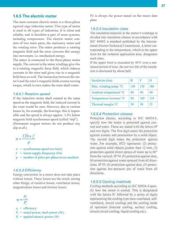
1.6.5 The electric motorThe most common electric motor is a three-phase squirrel cage induction motor. This type of motor is used in all types of industries. It is silent and reliable, and is therefore a part of most systems, including compressors. The electric motor con-sists of two main parts, the stationary stator and the rotating rotor. The stator produces a rotating magnetic field and the rotor converts this energy into movement, i.e. mechanical energy.The stator is connected to the three-phase mains supply. The current in the stator windings give rise to a rotating magnetic force field, which induces currents in the rotor and gives rise to a magnetic field there as well. The interaction between the sta-tor’s and the rotor’s magnetic fields creates turning torque, which in turn makes the rotor shaft rotate.
1.6.5.1 Rotation speedIf the induction motor shaft rotated at the same speed as the magnetic field, the induced current in the rotor would be zero. However, due to various losses in, for example, the bearings, this is impos-sible and the speed is always approx. 1-5% below magnetic field synchronous speed (called “slip”). (Permanent magnet motors do not produce any slip at all.)
n = synchronous speed (rev/min)f = motor supply frequency (Hz)p = number of poles per phase (even number)
1.6.5.2 EfficiencyEnergy conversion in a motor does not take place without losses. These losses are the result, among other things, of resistive losses, ventilation losses, magnetization losses and friction losses.
η = efficiencyP2 = stated power, shaft power (W)P1 = applied electric power (W)
P2 is always the power stated on the motor data plate.
1.6.5.3 Insulation classThe insulation material in the motor’s windings is divided into insulation classes in accordance with IEC 60085, a standard published by the Interna-tional Electro-Technical Commission. A letter cor-responding to the temperature, which is the upper limit for the isolation application area, designates each class. If the upper limit is exceeded by 10°C over a sus-tained period of time, the service life of the insula-tion is shortened by about half. Insulation class B F H
Max. winding temp. °C 130 155 180
Ambient temperature °C 40 40 40
Temperature increase °C 80 105 125
Thermal margin °C 10 10 15
1.6.5.4 Protection classesProtection classes, according to IEC 60034-5, specify how the motor is protected against con-tact and water. These are stated with the letters IP and two digits. The first digit states the protection against contact and penetration by a solid object. The second digit states the protection against water. For example, IP23 represents: (2) protec-tion against solid objects greater than 12 mm, (3) protection against direct sprays of water up to 60° from the vertical. IP 54: (5) protection against dust, (4) protection against water sprayed from all direc-tions. IP 55: (5) protection against dust, (5) protec-tion against low-pressure jets of water from all directions.
1.6.5.5 Cooling methodsCooling methods according to IEC 60034-6 spec-ify how the motor is cooled. This is designated with the letters IC followed by a series of digits representing the cooling type (non-ventilated, self-ventilated, forced cooling) and the cooling mode of operation (internal cooling, surface cooling, closed-circuit cooling, liquid cooling etc.).
CAM_edition8_2014.indd 27 13/04/15 14:50

28
1.6.5.6 Installation methodThe installation method states, according to IEC 60034-7, how the motor should be installed. This is designated by the letters IM and four digits. For example, IM 1001 represents: two bearings, a shaft with a free journal end, and a stator body with feet. IM 3001: two bearings, a shaft with a free journal end, a stator body without feet, and a large fl ange with plain securing holes.
1.6.5.7 Star (Y) and delta (∆) connectionsA three-phase electric motor can be connected in two ways: star (Y) or delta (∆). The winding phas-es in a three-phase motor are marked U, V and W (U1-U2; V1-V2; W1-W2). Standards in the United States make reference to T1, T2, T3, T4, T5, T6. With the star (Y) connection the “ends” of motor winding’s phases are joined together to form a zero point, which looks like a star (Y).
This illustrates the motor windings connected in a star confi guration, and how the connection strips are placed on the star-connected motor terminal. The example shows the connection to a 690V supply.
1:25
Uf
If
400V
400V
400V
Motor windings
L1
L2
L3
V2V1
W1
W2
U1
U2
690V
690V
690V
W2 U2 V2
U1 V1 W1
L1 L2 L3Star connection
Motor terminal
Uf
Uf
This illustrates the motor windings connected in a delta confi guration, and how the connection strips are placed on the delta-connected motor terminal. The example shows the connection to a 400V supply.
1:26
Uh
If
400V
Motor winding
V V
400V
400V
400V
400V
W U V
U V W
L L LDelta connection
Motor terminal
400V
If
1 2
Ih
Uh
Uh
2 2 2
21 3
L1
L3
1 1 1W
2
W1
U1
U2
L2
CAM_edition8_2014.indd 28 13/04/15 14:50

29
The mains supply is connected to a three-phase motor’s terminals marked U, V and W. The phase sequence is L1, L2 and L3. This means the motor will rotate clockwise seen from “D” the drive end. To make the motor rotate anticlockwise two of the three conductors connected to the starter or to the motor are switched. Check the oper-ation of the cooling fan when rotating anticlockwise.
The torque curve for a squirrel cage induction motor. When the motor starts the torque is high. Mst = start torque, Mmax = max torque (“cutting torque”), Mmin = min. torque (“saddle torque”), Mn = rated torque.
A star/delta started induction motor torque curve com-bined with a torque demand curve for a screw compres-sor. The compressor is unloaded (idling) during star operations. When the speed has reached approx. 90-95% of the rated speed the motor is switched to the delta mode, the torque increases, the compressor is loadedand fi nds its working point.
1:27
1:28
1:29
1:27
Torque
Mst Mmin Mmax
Mn
rpm
A phase voltage (phase voltage = main voltage/√3; for example 400V = 690/√3 ) will lie across the windings. The current Ih in towards the zero point becomes a phase current and accordingly a phase current will fl ow If = Ih through the windings.
With the delta (∆) connection the beginning and ends are joined between the different phases, which then form a delta (∆). As a result, there will be a main voltage across the windings. The current Ih into the motor is the main current and this will be divided between the windings to give a phase current through these, Ih/√3 = If. The same motor can be connected as a 690 V star connection or 400 V delta connection. In both cases the voltage across the windings will be 400 V. The current to the motor will be lower with a 690 V star connec-tion than with a 400 V delta connection. The rela-tion between the current levels is √3.
On the motor plate it can, for example, state 690/400 V. This means that the star connection is intended for the higher voltage and the delta con-nection for the lower. The current, which can also be stated on the plate, shows the lower value for the star-connected motor and the higher for the delta-connected motor.
1.6.5.8 TorqueAn electric motor’s turning torque is an expres-sion of the rotor turning capacity. Each motor has a maximum torque. A load above this torque means that the motor does not have the capabil-ity to rotate. With a normal load the motor works signifi cantly below its maximum torque, however, the start sequence will involve an extra load. The characteristics of the motor are usually presented in a torque curve.
CAM_edition8_2014.indd 29 13/04/15 14:50

CAM_edition8_2014.indd 30 13/04/15 14:50

2 COMPRESSORS AND AUXILIARY EQUIPMENT
CAM_edition8_2014.indd 31 13/04/15 14:50

32
2.1 DISPLACEMENT COMPRESSORS
2.1.1 Displacement compressorsA displacement compressor encloses a volume of gas or air and then increases the pressure by reduc-ing the enclosed volume through the displacement of one or more moving members.
2.1.2 Piston compressorsThe piston compressor is the oldest and most com-mon of all industrial compressors. It is available in single-acting or double-acting, oil-lubricated or oil-free variants, with various numbers of cylin-ders in different confi gurations. With the excep-tion of very small compressors having vertical cyl-inders, the V-confi guration is the most common for small compressors.
On double-acting, large compressors the L-confi g-uration with a vertical low pressure cylinder and horizontal high pressure cylinder offers immense benefi ts and has become the most common design.Oil-lubricated compressors normally work with splash lubrication or pressure lubrication. Most compressors have self-acting valves. A self-acting valve opens and closes through the effect of pres-sure differences on both sides of the valve disk.
2.1.3 Oil-free piston compressorsOil-free piston compressors have piston rings made of PTFE or carbon, and alternatively, the piston and cylinder wall can be profi led (toothed) as on labyrinth compressors. Larger machines are equipped with a crosshead and seals on the gud-geon pins, and a ventilated intermediate piece to prevent oil from being transferred from the crank-case and into the compression chamber. Smaller compressors often have a crankcase with bearings that are permanently sealed.
2.1.4 Diaphragm compressors2.1.4 Diaphragm compressors
Piston compressor.
2:1 2.1.4 Diaphragm compressors
Piston compressor.
CAM_edition8_2014.indd 32 13/04/15 14:50
33
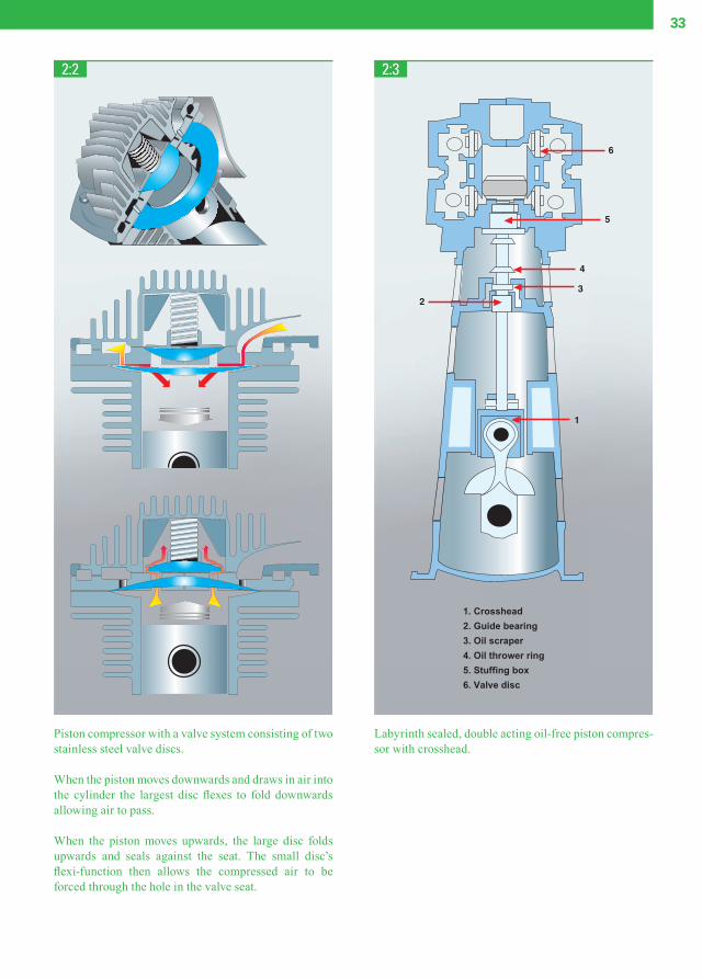
Piston compressor with a valve system consisting of two stainless steel valve discs.
When the piston moves downwards and draws in air into the cylinder the largest disc fl exes to fold downwards allowing air to pass.
When the piston moves upwards, the large disc folds upwards and seals against the seat. The small disc’s fl exi-function then allows the compressed air to be forced through the hole in the valve seat.
Labyrinth sealed, double acting oil-free piston compres-sor with crosshead.
2:2 2:3
1
23
4
5
6
1. Crosshead2. Guide bearing3. Oil scraper4. Oil thrower ring5. Stuffing box6. Valve disc
CAM_edition8_2014.indd 33 13/04/15 14:50

34
2.1.4 Diaphragm compressorDiaphragm compressors form another group. Their diaphragm is actuated mechanically or hydrauli-cally. The mechanical diaphragm compressors are used with a small fl ow and low pressure or as vac-uum pumps. Hydraulic diaphragm compressors are used for high pressure applications.
2.1.5 Twin screw compressorsThe principle for a rotating displacement compres-sor in twin screw form was developed during the 1930s, when a rotating compressor with high fl ow rate and stable fl ow under varying pressure condi-tions was required. The twin screw element’s main parts are the male and female rotors, which rotate in opposite directions while the volume between them and the housing decreases. Each screw element has a fi xed, build-in pressure ratio that is dependent on its length, the pitch of the screw and the form of the discharge port. To attain maximum effi ciency, the build-in pressure ratio must be adapted to the required working pressure.The screw compressor is generally not equipped with valves and has no mechanical forces that cause unbalance. This means it can work at a high shaft speed and can combine a large fl ow rate with
small exterior dimensions. An axial acting force, dependent on the pressure difference between the inlet and outlet, must be overcome by the bear-ings.
2.1.5.1 Oil-free screw compressorsThe fi rst twin screw compressors had a symmet-ric rotor profi le and did not use any cooling liq-uid inside the compression chamber. These were called oil-free or dry screw compressors. Mod-ern, high-speed, oil-free screw compressors have asymmetric screw profi les, resulting in signifi -cantly improved energy effi ciency, due to reduced internal leakage.External gears are most often used to synchronize the position of the counter-rotating rotors. As the rotors neither come into contact with each other nor with the compressor housing, no lubrication is required inside the compression chamber. Conse-quently, the compressed air is completely oil-free. The rotors and housing are manufactured with ultimate precision to minimize leakage from the pressure side to the inlet. The build-in pressure ratio is limited by the limiting temperature dif-ference between the inlet and the discharge. This is why oil-free screw compressors are frequently built with several stages and inter-stage cooling to reach higher pressures.
Mechanical diaphragm compressor, in which a conventional crankshaft transfers the reciprocating motion via a connect-ing rod to the diaphragm.
2:4
Diaphragm
Connecting rod
Flywheel
Shaft
Cam
Counterbalance weight
Clutch
CAM_edition8_2014.indd 34 13/04/15 14:50

35
This illustrates compression in a twin screw compressor. Figure 1: air fi lls the space between the rotors, Fig. 2-4: gradu-ally the enclosed space decreases and pressure increases.
Typical oil lubricated screw compressor element and drive.
2:5
2:6
CAM_edition8_2014.indd 35 13/04/15 14:51
36
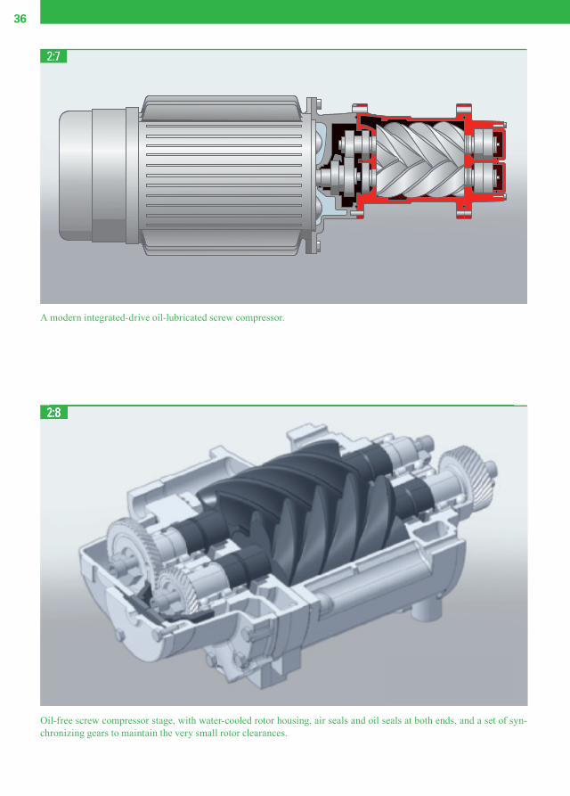
A modern integrated-drive oil-lubricated screw compressor.
2:7
An oil lubricated screw compressor element.
Oil-free screw compressor stage, with water-cooled rotor housing, air seals and oil seals at both ends, and a set of syn-chronizing gears to maintain the very small rotor clearances.
2:82:8
CAM_edition8_2014.indd 36 13/04/15 14:51

37
2.1.5.2 Liquid-injected screw compressorsIn liquid-injected screw compressors, a liquid is injected into the compression chamber and often into the compressor bearings. Its function is to cool and lubricate the compressor element’s mov-ing parts, to cool the air being compressed inter-nally, and to reduce the return leakage to the inlet.Today oil is the most commonly injected liquid due to its good lubricating and sealing properties, however, other liquids are also used, for example, water or polymers. Liquid-injected screw com-pressor elements can be manufactured for high pressure ratios, with one compression stage usu-ally being suffi cient for pressure up to 14 and even 17 bar, albeit at the expense of reduced energy effi -ciency.
2.1.6 Tooth compressorsThe compression element in a tooth compressor consists of two rotors that rotate in opposite direc-tions inside a compression chamber.The compression process consists of intake, com-pression and outlet. During the intake phase, air is drawn into the compression chamber until the rotors block the inlet. During the compression phase, the drawn in air is compressed in the com-pression chamber, which gets smaller as the rotors rotate.The outlet port is blocked during compression by one of the rotors, while the inlet is open to draw in new air into the opposite section of the compres-sion chamber.
Oil-injected screw compressor fl ow diagram.
Oil-free screw compressor fl ow diagram.
2:9
2:10
CAM_edition8_2014.indd 37 13/04/15 14:51

38
Discharge takes place when one of the rotors opens the outlet port and the compressed air is forced out of the compression chamber. Both rotors are synchronized via a set of gear wheels. The maximum pressure ratio obtainable with an oil-free tooth compressor is limited by the limiting temperature difference between the inlet and the discharge. Consequently, several stages with inter-stage cooling are required for higher pressures.
2.1.7 Scroll compressorsA scroll compressor is a type of (usually) oil-free orbiting displacement compressor, i.e. it com-presses a specifi c amount of air into a continu-ously decreasing volume. The compressor element consists of a stator spiral fi xed in a housing and a motor-driven eccentric, orbiting spiral. The spirals are mounted with 180° phase displacement to form air pockets with a gradually varying volume.This provides the scroll elements with radial sta-bility. Leakage is minimized because the pressure difference in the air pockets is lower than the pres-sure difference between the inlet and the outlet.The orbiting spiral is driven by a short-stroke crankshaft and runs eccentrically around the cen-tre of the fi xed spiral. The inlet is situated at the top of the element housing.When the orbiting spiral moves, air is drawn in and is captured in one of the air pockets, where it is compressed gradually while moving towards the centre where the outlet port and a non-return valve are situated. The compression cycle is in progress for 2.5 turns, which virtually gives constant and pulsation-free air fl ow. The process is relatively silent and vibration-free, as the element has hardly any torque variation as compared to a piston com-pressor, for example.
Compression principle of the double tooth compressor.
Rotor set of a double tooth compressor.
2:11
2:12
Inlet ports
End of intake phase Start intake phaseStart transportation
Start delivery
Intake phase Intake phaseTranportation
DeliveryCompressionEnd of delivery
End of compression
Male rotor
Outlet ports
Female rotor
CAM_edition8_2014.indd 38 13/04/15 14:51

39
A scroll compressor cross section.
Compression principle of a scroll compressor.
2:13
2:14
CAM_edition8_2014.indd 39 13/04/15 14:51

40
2.1.8 Vane compressorsThe operating principle for a vane compressor is the same as for many compressed air expansion motors. The vanes are usually manufactured of special cast alloys and most vane compressors are oil-lubricated.A rotor with radial, movable blade-shaped vanes is eccentrically mounted in a stator housing. When it rotates, the vanes are pressed against the stator walls by centrifugal force. Air is drawn in when the distance between the rotor and stator increas-es. The air is captured in the different compressor pockets, which decrease in volume with rotation. The air is discharged when the vanes pass the out-let port.
2:15
2:16
Outlet
IntakeCompression
2.1.9 Roots blowersA Roots blower is a valve-less displacement com-pressor without internal compression. When the compression chamber comes into contact with the outlet port, compressed air fl ows back into the housing from the pressure side. Subsequently, fur-ther compression takes place when the volume of the compression chamber further decreases with continued rotation. Accordingly, compression takes place against full counter-pressure, which results in low effi ciency and a high noise level.Two identical, usually symmetrical, counter-rotating rotors work in a housing, synchronized by means of a set of gear wheels. Blowers are usually air-cooled and oil-free. Their low effi ciency lim-its these blowers to very low pressure applications and compression in a single stage, even if two- and three-stage versions are available. Roots blow-ers are frequently used as vacuum pumps and for pneumatic conveyance.
Compression principle of a roots blower.
B
A
B
A
BA
A
B
CAM_edition8_2014.indd 40 13/04/15 14:51

41
2.2 DYNAMIC COMPRESSORS
2.2.1 Dynamic compressors in generalDynamic compressors are available in both axial and radial designs. They are frequently called turbocompressors. Those with radial design are called centrifugal compressors. A dynamic com-pressor works at a constant pressure, unlike, for example, a displacement compressor, which works with a constant fl ow. The performance of a dynamic compressor is affected by external conditions: for example, a change in the inlet temperature results in a change in the capacity.
2.2.2 Centrifugal compressorsA centrifugal compressor is characterized by its radial discharge fl ow. Air is drawn into the cen-tre of a rotating impeller with radial blades and is pushed out towards the perimeter of the impeller
by centrifugal forces. The radial movement of the air results simultaneously in a pressure rise and a generation of kinetic energy. Before the air is led to the centre of the impeller of the next compres-sor stage, it passes through a diffuser and a volute where the kinetic energy is converted into pres-sure.Each stage takes up a part of the overall pres-sure rise of the compressor unit. In industrialmachinery, the maximum pressure ratio of a cen-trifugal compressor stage is often not more than 3. Higher pressure ratios reduce the stage effi -ciency. Low pressure, single-stage applications are used, for instance, in wastewater treatment plants. Multi-stage applications allow the possibil-ity of inter-cooling to reduce the power require-ment. Multiple stages can be arranged in series on a single, low-speed shaft. This concept is often used in the oil and gas or process industry. The pressure ratio per stage is low, but a large number of stages and/or multiple compressor sets in series are used to achieve the desired outlet pressure. For air compression applications, a high speed gearbox is integrated with the compressor stages to rotate the impellers on high speed pinions.
Three-stage integral gear centrifugal compressor.
2:17
CAM_edition8_2014.indd 41 13/04/15 14:51

42
The impeller can have either an open or closed design. Open design is most commonly used for high speed air applications. The impeller is nor-mally made of special stainless steel alloy or alu-minum. The impeller shaft speed is very high com-pared to that of other types of compressor. Speeds of 15,000-100,000 rpm are common.This means that journaling on the high speed com-pressor shaft or pinion takes place using plain oil-
fi lm bearings instead of roller bearings. Alterna-tively, air fi lm bearings or active magnetic bearings can be used for a completely oil-free machine.Two impellers are mounted on each end of the same shaft to counteract the axial loads caused by the pressure differences. Typically 2 or 3 stages with intercoolers are used for standard compressed air applications. In a modern confi guration of the centrifugal air compressor, ultra-high speed electric motors are used to drive the impellers directly. This tech-nology creates a compact compressor without a gearbox and associated oil-lubrication system, thereby making it a completely oil-free compres-sor design. Each centrifugal compressor must be sealed in a suitable manner to reduce leakage along the shaft where it passes through the compressor housing. Many types of seals are used and the most advanced can be found on high-speed compressors intended for high pressures. The most common types are labyrinth seals, ring seals or controlled gap seals, (usually graphite seals) and mechanical seals.
Axial compressor.
Modern high-speed direct-drive centrifugal compressor.
2:19
2:18
CAM_edition8_2014.indd 42 13/04/15 14:51
43
2.2.3 Axial compressorsAn axial compressor has axial fl ow, whereby the air or gas passes along the compressor shaft through rows of rotating and stationary blades. In this way, the velocity of the air is gradually increased at the same time that the stationary blades convert the kinetic energy to pressure. A balancing drum is usually built into the compressor to counterbal-ance axial thrust.Axial compressors are generally smaller and light-er than their equivalent centrifugal compressors and normally operate at higher speeds. They are used for constant and high volume fl ow rates at a relatively moderate pressure, for instance, in ven-tilation systems. Given their high rotational speed, they are ideally coupled to gas turbines for elec-tricity generation and aircraft propulsion.
2.3 OTHER COMPRESSORS
2.3.1 Vacuum pumpsA vacuum signifi es a pressure lower than atmo-spheric pressure. A vacuum pump is a compres-sor that compresses a vacuum to higher pressures, generally to atmospheric pressure. A typical char-
acteristic of a vacuum pump is that it works with a very high pressure ratio. This explains why multi-stage machines are common. Multi-stage air com-pressors can also be used for vacuums within the pressure range 1 bar(a) and 0.1 bar(a).
2.3.2 Booster compressorsA booster compressor is a compressor that com-presses compressed air to a much higher pressure. It may be used to compensate the pressure drop in long pipelines or for applications in which a higher
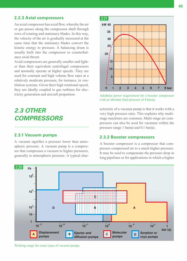
Working range for some types of vacuum pumps.
2:20
Adiabatic power requirement for a booster compressor with an absolute fi nal pressure of 8 bar(a).
2:21
CAM_edition8_2014.indd 43 13/04/15 14:51

44
pressure is required for a sub-process. Booster compressors may be single-stage or multi-stage and can be of a dynamic or displacement type, but piston compressors are the most common. The power requirement for a booster compressor increases as the pressure ratio rises, whereas the mass fl ow drops. The curve for power requirement as a function of the inlet pressure has the same general form as the curve for a vacuum pump.
2.3.3 Pressure intensifi ersPressure intensifi ers are a form of booster com-pressors, driven by the compressed air medium itself (called the propellant). They can increase the pressure in a medium for special applications: for laboratory tests of valves, pipes and hoses. A pres-sure of 7 bar can be amplifi ed in a single stage to 200 bar or up to 1700 bar in multi-staged equip-
ment. The pressure intensifi er is only available for very small fl ows.
When the propellant fl ows in, the low-pressure pis-ton is pressed downwards and forces the medium in the high-pressure compression chamber out under high pressure. The intensifi er can work in a cycling process, up to a preset pressure level. All inert gases can be compressed in this way. Air can also be compressed in a pressure intensifi er, but must be completely oil-free to avoid self-ignition.
2.4 TREATMENT OF COMPRESSED AIR
2.4.1 Drying compressed airAll atmospheric air contains water vapor: more at high temperatures and less at lower temperatures. When the air is compressed the water concentra-tion increases. For example, a compressor with a working pressure of 7 bar and a capacity of 200 l/s that compresses air at 20˚C with a relative humidi-ty of 80% will release 10 liters/hour of water in the compressed air line. To avoid problems and distur-bances due to water precipitation in the pipes and connected equipment, the compressed air must be dried. This takes place using an after-cooler and drying equipment.The term “pressure dew point” (PDP) is used to describe the water content in the compressed air. It is the temperature at which water vapor condenses into water at the current working pressure. Low PDP values indicate small amounts of water vapor in the compressed air.
It is important to remember that atmospheric dew point can not be compared with PDP when com-paring different dryers. For example, a PDP of +2˚C at 7 bar is equivalent to –23˚C at atmospheric pressure. To use a fi lter to remove moisture (low-er the dew point) does not work. This is because further cooling leads to continued precipitation of condensation water. You can select the main type of drying equipment based on the pressure dew point. When taking cost into account, the lower the dew point required, the higher the investment
2:22
A cross section of a single stage pressure intensifi er.
1. Propellant2. Low pressure piston3. High pressure piston4. Seal5. Compression chamber6. Intake7. Outlet
CAM_edition8_2014.indd 44 13/04/15 14:51

45
and operating costs for air drying. Five techniques exist for removing the moisture from compressed air: cooling plus separation, over-compression, membranes, absorption and adsorption drying.
2.4.1.1 After-coolerAn after-cooler is a heat exchanger that cools the hot compressed air to precipitate the water that otherwise would condensate in the pipe system. It is water-cooled or air-cooled, is generally equipped with a water separator with automatic drainage and
should be placed close to the compressor. Approximately 80–90% of the precipitated con-densation water is collected in the after-cooler’s water separator. A common value for the tempera-ture of the compressed air after passing through the after-cooler is approx. 10˚C above the coolant temperature, but can vary depending on the type of cooler. An after-cooler is used in virtually all stationary installations. In most cases, an after-cooler is built into modern compressors.
A compressor that delivers 200 liters/second of air also supplies approx. 10 liters/hour of water when compressing air at 20˚C. Problems due to water precipitation in the pipes and equipment are avoided by the use of after-cooler and drying equipment.
Relation between dew point and pressure dew point.
2:23
2:24
CAM_edition8_2014.indd 45 13/04/15 14:51

46
2.4.1.2 Refrigerant dryerRefrigerant drying means that the compressed air is cooled, which allows a large amount of the water to condense and be separated. After cool-ing and condensing, the compressed air is reheated to around room temperature so that condensation does not form on the outside of the pipe system. This heat exchange between ingoing and outgoing compressed air also reduces the temperature of the incoming compressed air, and as such reduces the required cooling capacity of the refrigerant circuit.Cooling the compressed air takes place via a closed refrigerant system. Smart steering of the refriger-ant compressor via intelligent control algorithms can signifi cantly reduce the power consumption of modern refrigerant dryers. Refrigerant dryers are used for dew points between +2˚C to +10˚C and have a lower limit, which is the freezing point of the condensed water. They are available as either a freestanding machine or an integrated drying module inside the compressor. The latter has the advantage of having a small footprint and ensures optimized performance for the particular air com-pressor capacity.
Modern refrigerant dryers use refrigerant gases with a low Global Warming Potential (GWP), which means refrigerant gases that -when acciden-tally released into the atmosphere- contribute less to global warming. Future refrigerants will have
an even lower GWP value, as dictated by environ-mental legislation.
Different after-coolers and water separators. Water separators can work with cyclone separating or separation through changes in direction and speed.
Typical parameter changes with compression, after-cooling and refrigerant drying.
2:25
2:26
CAM_edition8_2014.indd 46 13/04/15 14:51

47
2.4.1.3 Over-compressionOver-compression is perhaps the easiest method for drying compressed air.Air is fi rst compressed to a higher pressure than the intended working pressure, which means that the concentration of water vapor increases. There-after the air is cooled and the water is separated as a result. Finally, the air is allowed to expand to the working pressure, and a lower PDP is attained. However, this method is only suitable for very small air fl ow rates, due to its high energy con-sumption.
2.4.1.4 Absorption dryingAbsorption drying is a chemical process in which water vapor is bound to absorption material. The
absorption material can either be a solid or liquid. Sodium chloride and sulfuric acid are frequently used, which means that the possibility of corrosion must be taken into consideration. This method is unusual and involves high consumption of absor-bent materials. The dew point is only lowered to a limited extent.
2.4.1.5 Adsorption dryingThe general working principle of adsorption dryers is simple: moist air fl ows over hygroscopic mate-rial (typical materials used are silica gel, molecular sieves, activated alumina) and is thereby dried.The exchange of water vapor from the moist com-pressed air into the hygroscopic material or “desic-cant”, causes the desiccant to gradually be saturat-
Operational principle of refrigerant drying.
2:27
CAM_edition8_2014.indd 47 13/04/15 14:51

48
Oil-free screw compressor with a MD model adsorption dryer.
2:29
ed with adsorbed water. Therefore, the desiccant needs to be regenerated regularly to regain its dry-ing capacity, and adsorption dryers are typically built with two drying vessels for that purpose: the fi rst vessel will dry the incoming compressed air while the second one is being regenerated. Each vessel (“tower”) switches tasks when the other tower is completely regenerated. Typical PDP that can be achieved is -40°C, which makes these dry-ers suitable for providing very dry air for more critical applications.There are 4 different ways to regenerate the des-iccant, and the method used determines the type of adsorption dryer. More energy-effi cient types are usually more complex and, consequently, more expensive.
1) Purge regenerated adsorption dryers (also called “heatless-type dryers”).
These dryers are best suited for smaller air fl ow rates. The regeneration process takes place with the help of expanded compressed air (“purged”) and requires approx. 15–20% of the dryer’s nominal capacity at 7 bar(e) working pressure.
2) Heated purge regenerated dryers. These dryers heat up the expanded purge air by
means of an electric air heater and hence limit the required purge fl ow to around 8%. This type uses 25% less energy than heatless-type dryers.
3) Blower regenerated dryers. Ambient air is blown over an electric heater and
brought into contact with the wet desiccant in order to regenerate it. With this type of dryer, no compressed air is used to regenerate the des-iccant material, thus the energy consumption is 40% lower than for heatless-type dryers.
4) Heat of compression dryers (“HOC” dryers). In HOC dryers the desiccant is regenerated
by using the available heat of the compressor. Instead of evacuating the compressed air heat in an after-cooler, the hot air is used to regenerate the desiccant.
This type of dryer can provide a typical PDP of -20°C without any energy being added. A lower PDP can also be obtained by adding extra heat-ers.
Guaranteed separation and drainage of the con-densation water must always be arranged before adsorption drying. If the compressed air has been produced using oil-lubricated compressors, an oil separating fi lter must also be fi tted upstream of the drying equipment. In most cases a particle fi lter is required after adsorption drying.HOC dryers can only be used with oil-free com-pressors since they produce heat at suffi ciently high temperatures for dryer regeneration.
Purge regenerated adsorption dryer (also called “heat-less type dryer”).
2:28
CAM_edition8_2014.indd 48 13/04/15 14:51
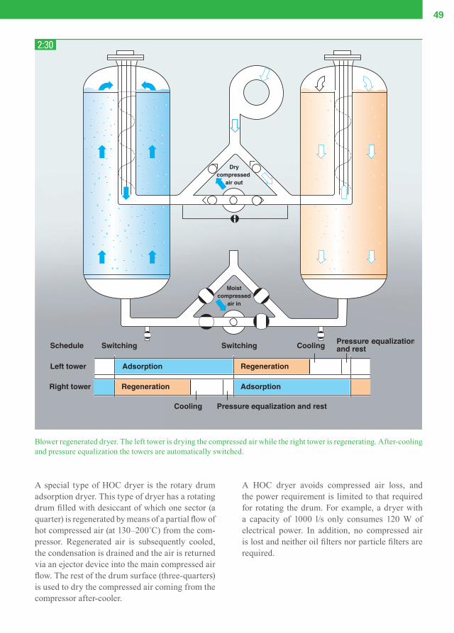
49
A special type of HOC dryer is the rotary drum adsorption dryer. This type of dryer has a rotating drum fi lled with desiccant of which one sector (a quarter) is regenerated by means of a partial fl ow of hot compressed air (at 130–200˚C) from the com-pressor. Regenerated air is subsequently cooled, the condensation is drained and the air is returned via an ejector device into the main compressed air fl ow. The rest of the drum surface (three-quarters) is used to dry the compressed air coming from the compressor after-cooler.
Blower regenerated dryer. The left tower is drying the compressed air while the right tower is regenerating. After-cooling and pressure equalization the towers are automatically switched.
2:30
A HOC dryer avoids compressed air loss, and the power requirement is limited to that required for rotating the drum. For example, a dryer with a capacity of 1000 l/s only consumes 120 W of electrical power. In addition, no compressed air is lost and neither oil fi lters nor particle fi lters are required.
CAM_edition8_2014.indd 49 13/04/15 14:51
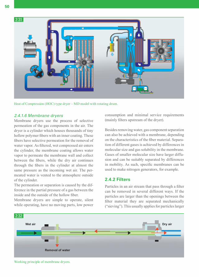
50
2.4.1.6 Membrane dryersMembrane dryers use the process of selective permeation of the gas components in the air. The dryer is a cylinder which houses thousands of tiny hollow polymer fi bers with an inner coating. These fi bers have selective permeation for the removal of water vapor. As fi ltered, wet compressed air enters the cylinder, the membrane coating allows water vapor to permeate the membrane wall and collect between the fi bers, while the dry air continuesthrough the fi bers in the cylinder at almost the same pressure as the incoming wet air. The per-meated water is vented to the atmosphere outside of the cylinder.The permeation or separation is caused by the dif-ference in the partial pressure of a gas between the inside and the outside of the hollow fi ber.Membrane dryers are simple to operate, silent while operating, have no moving parts, low power
Heat of Compression (HOC) type dryer – MD model with rotating drum.
2:31
Working principle of membrane dryers.
2:32
Wet air
Removal of water
Dry air
consumption and minimal service requirements (mainly fi lters upstream of the dryer).
Besides removing water, gas component separation can also be achieved with a membrane, depending on the characteristics of the fi ber material. Separa-tion of different gases is achieved by differences in molecular size and gas solubility in the membrane. Gases of smaller molecular size have larger diffu-sion and can be suitably separated by differences in mobility. As such, specifi c membranes can be used to make nitrogen generators, for example.
2.4.2 FiltersParticles in an air stream that pass through a fi lter can be removed in several different ways. If the particles are larger than the openings between the fi lter material they are separated mechanically (“sieving”). This usually applies for particles larger
CAM_edition8_2014.indd 50 13/04/15 14:51

51
than 1 mm. The fi lter effi ciency in this regard increases with a tighter fi lter material, consisting of fi ner fi bers. Particles smaller than 1 mm are collected on fi ber material by 3 physical mechanisms: inertial impac-tion, interception and diffusion.Impaction occurs for relatively large particles and/or for high gas velocities. Due to the large inertia of the heavy particle, it does not follow the stream-lines but instead travels straight ahead and collides with the fi ber. This mechanism mainly occurs for particles above 1µm and becomes increasingly important with the increasing size of the particles.Interception occurs when a particle does follow the streamline, but the radius of the particle is larger than the distance between the streamline and the fi ber perimeter.
Particle deposition due to diffusion occurs when a very small particle does not follow the streamlines but moves randomly across the fl ow due to Brown-ian motion. It becomes increasingly important with smaller particle size and lower air velocity.
The particle-separating capacity of a fi lter is a result of the combined sub-capacities (for the dif-ferent particle sizes) as set forth above. In reality, each fi lter is a compromise, as no fi lter is effi cient across the entire particle size range. Even the effect of the stream velocity on the separating capacity for different particle sizes is not a decisive factor. Generally, particles between 0.1µm and 0.2µm are the most diffi cult to separate (Most Penetrating Particle Size). As stated above, the total capturing effi ciency of a coalescence fi lter can be attributed to a combina-tion of all occurring mechanisms. Obviously, the importance of each mechanism, the particle sizes for which they occur and the value of the total effi -ciency heavily depend on the particle size distri-bution of the aerosol, the air speed and the fi ber diameter distribution of the fi lter media.
Oil and water in aerosol form behave similar to other particles and can also be separated using a coalescing fi lter. In the fi lter these liquid aerosols coalesce to larger droplets that sink to the bot-tom of the fi lter due to gravitational forces. The
Particle collision mechanisms in fi lters.
Filter effi ciency as a function of particle size.
2:33
2:34
ImpactionParticle
Particle
Particle
Interception
Diffusion
Fiber
Fiber
Fiber
1
0
0.1 1 10 µm
Filt
er e
ffic
ien
cy
Diffusion Interception
Impaction Total efficiency
E
CAM_edition8_2014.indd 51 13/04/15 14:51
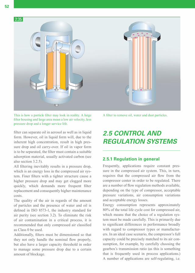
52
fi lter can separate oil in aerosol as well as in liquid form. However, oil in liquid form will, due to the inherent high concentration, result in high pres-sure drop and oil carry-over. If oil in vapor form is to be separated, the fi lter must contain a suitable adsorption material, usually activated carbon (see also section 3.2.5).All fi ltering inevitably results in a pressure drop, which is an energy loss in the compressed air sys-tem. Finer fi lters with a tighter structure cause a higher pressure drop and may get clogged more quickly, which demands more frequent fi lter replacement and consequently higher maintenance costs.The quality of the air in regards of the amount of particles and the presence of water and oil is defi ned in ISO 8573-1, the industry standard for air purity (see section 3.2). To eliminate the risk of air contamination in a critical process, it is recommended that only compressed air classifi ed as Class 0 be used.Additionally, fi lters must be dimensioned so that they not only handle the nominal fl ow properly, but also have a larger capacity threshold in order to manage some pressure drop due to a certain amount of blockage.
2.5 CONTROL AND REGULATION SYSTEMS
2.5.1 Regulation in generalFrequently, applications require constant pres-sure in the compressed air system. This, in turn, requires that the compressed air fl ow from the compressor center in order to be regulated. There are a number of fl ow regulation methods available, depending on the type of compressor, acceptable pressure variations, air consumption variations and acceptable energy losses.Energy consumption represents approximately 80% of the total life cycle cost for compressed air, which means that the choice of a regulation sys-tem must be made carefully. This is primarily due to signifi cant differences in performance broadly with regard to compressor types or manufactur-ers. In an ideal case scenario, the compressor’s full capacity could be precisely matched to its air con-sumption, for example, by carefully choosing the gearbox’s transmission ratio (as this is something that is frequently used in process applications.) A number of applications are self-regulating, i.e.
This is how a particle fi lter may look in reality. A large fi lter housing and large area mean a low air velocity, less pressure drop and a longer service life.
A fi lter to remove oil, water and dust particles.
2:35
CAM_edition8_2014.indd 52 13/04/15 14:52

53
increased pressure creates an increased fl ow rate, and as a result, stable systems. Examples include pneumatic conveying systems, ice prevention, chilling systems etc. However, in most applica-tions, the fl ow rate must be regulated. This is usually performed using regulation equipment that is integrated in the compressor. There are two main groups of regulation systems:
1. Continuous fl ow rate regulation involves the continuous control of the drive motor or inlet valve according to variations in pressure. The result is normally small pressure variations (0.1 to 0.5 bar), depending on the regulation system’s amplifi cation and its regulating speed.
2. Load/unload regulation is the most common regulation method and involves the accep-tance of somewhat larger variations in pressure between two limit values. This takes place by completely stopping the fl ow rate at the higher pressure (off-loading) and resuming the fl ow rate (loading) when the pressure has dropped to the lowest limit value. Pressure variations depend on the permitted number of load/unload cycles per time unit, but normally lie within the 0.3 to 1 bar range.
2.5.2 Regulation principles for displacement compressors
2.5.2.1 Pressure reliefThe original method for regulating compressors was to use a pressure relief valve to release excess air pressure into the atmosphere. The valve in its simplest design can be spring-loaded, whereby the spring tension determines the fi nal pressure.Frequently a servo-valve controlled by a regulator is used instead. The pressure can then be easily controlled and the valve can also act as an off-load-ing valve when starting a compressor under pres-sure. Pressure relief creates a signifi cant energy requirement, as the compressor must work con-tinuously against full counterpressure.A variant, which is used on smaller compressors, is to unload the compressor by fully opening the valve so that the compressor works against atmo-spheric pressure. Power consumption is signifi -cantly lower using this variant method.
2:36
2:37
CAM_edition8_2014.indd 53 13/04/15 14:52

54
2.5.2.5 Start/stopCompressors below 5–10 kW are often controlled by completely stopping the electric motor when the pressure reaches an upper limit value and by restarting it when the pressure drops below the lower limit value. This method demands a large system buffer volume or large pressure differ-ence between the upper and lower limits, in order to minimize the heat load on the electric motor. This is an energy-effi cient and effective regulation method, provided the number of starts is kept low.
2.5.2.6 Speed regulationA combustion engine, gas turbine or frequency-controlled electric motor controls the compres-sor’s speed and, consequently, the fl ow rate. It is an effi cient method for maintaining a steady outgoing pressure and lower energy consumption.The regulation range varies with the type of compressor,and is largest for liquid-injected com-
2.5.2.2 BypassBypass regulation serves the same function as pressure relief, in principle. The difference lies in the fact that the pressure relieved air is cooled and returned to the compressor’s inlet. This method is often used on process compressors where the gas is unsuitable or too valuable to be released into the atmosphere.
2.5.2.4 Pressure relief with throttled inletThis is the most common regulation method cur-rently in use. It combines a maximum regulation range (0-100%) with low energy consumption: only 15–30% of full load power with an off-loaded compressor (zero fl ow). The inlet valve is closed, but with a small opening used at the same time a blow-off valve opens and releases the discharge air from the compressor. The compressor element therefore works with a vacuum in the inlet and low counterpressure. It is important that pressure relief be carried out
2:38 2:40
2:39
2:41
P
2.5.2.3 Throttling the inletThrottling is a simple method to reduce fl ow by increasing the pressure ratio across the compres-sor, according to the induced under-pressure in the inlet. This method is, however, limited to a small regulation range. Liquid-injected compressors, which can overcome such a high pressure ratio, can be regulated down to 10% of maximum capac-ity. The throttling method creates a relatively high energy requirement, due to the high pressure ratio.
quickly and that the released air volume is limited, in order to avoid unnecessary losses during the transition from loaded to unloaded. The system demands a system buffer volume (air receiver), the size of which is determined by the desired dif-ference between loading and off-loading pressure limits and by the permitted number of unloading cycles per hour.
P
CAM_edition8_2014.indd 54 13/04/15 14:52

55
2:42
2:43
Off-loading device for a piston compressor.
pressors. Frequently, speed regulation is combined with start-stop at low degrees of loading and pres-sure relief at standstill.
2.5.2.8 Suction valve unloadingPiston compressors can be effectively regulated by mechanically forcing the inlet valves into the open position. As a result, air is pumped out and into the cylinder with minimal energy loss that is often lower than 10% of the full-load shaft power. Double-acting piston compressors generally pro-vide multi-stage off-loading, whereby one cylinder at a time is off-loaded to better match the fl ow rate to the demand. An odd method used for process compressors is to allow the inlet valve to be open during a smaller or greater part of the piston stroke to provide nearly continuous fl ow rate control.
2.5.2.9 Load–unload–stopThis is the most common regulation method used for compressors with greater than 5 kW capacity, and it combines a large regulation range with low losses. It is, in practice, a combination of the start/stop method and different off-loading systems. For additional information, please see 2.5.4.2.
2.5.2.7 Variable discharge portThe fl ow rate of screw compressors can be regu-lated by moving the position of the discharge port into the housing, in the rotors’ lengthways direc-tion, towards the inlet. However, this method generates high power consumption and is rather unusual.
CAM_edition8_2014.indd 55 13/04/15 14:52

56
2.5.3 Regulation principles for dynamic compressors
2.5.3.2 Outlet regulationVariable outlet guide vanes (diffuser):To further improve the regulation range, the fl ow in the compressor stage’s diffuser may also be controlled. Regulation down to 30% with main-tained pressure is common. Usage is limited to single-stage compressors, due to the complexity and increased costs.
Pressure relief:The original method for regulating dynamic com-pressors was to use a pressure relief valve or blow-off valve to release excess compressed air into the atmosphere. In principle, this method works iden-tically as with pressure relief on a displacement compressor.
2.5.3.3 Load–unload–stopPreviously mentioned regulation methods can be combined to control the compressor unit. Two modes are commonly used:
- Modulating: The excess fl ow is released into the atmo-
sphere (or the inlet), but energy consumption is unchanged.
- Auto dual: The fl ow turndown of the unit will be limited
to the turndown of the intake valve and/or the outlet guide vanes for fl ows below the turndown limit. The regulation system fully closes the inlet valve at the same time as the compressor’s out-let is opened to the atmosphere (compare with the displacement compressor). The off-loading power is still relatively high, representing 20% of the full load power, depending on the design of the impeller etc.
2.5.3.4 Speed regulationSpeed regulation has a similar effect as the use of inlet guide vanes. Flow can be varied with constant pressure within the compressor turndown range.At higher powers, speed variation is less advanta-geous, due to the high cost of the required drive installation.
2:44
2.5.3.1 Inlet regulationThrottling the inlet:The inlet can be throttled on a dynamic compres-sor to continuously reduce the capacity of the com-pressor. The minimum fl ow is determined when the pressure ratio reaches the pump limit and the machine becomes unstable (surge).The regulation range is determined by the design of the machine (e.g. the number of stages and the impeller design) but also to a large degree by external factors such as counterpressure, suction temperature, and coolant temperature. The mini-mum fl ow often varies between 60% and 85% of the maximum fl ow.
Inlet guide vanes:Vanes arranged as radial blades in the intake cause the drawn-in gas to rotate while the fl ow is throttled. The method has the same impact as throttling, but offers a greater regulation range and features improved energy utilization. Regulation down to 50–70% of the design fl ow is a typical value. There is also the possibility of increasing slightly the capacity and pressure of the compres-sor to a certain degree, by turning the vanes in the opposite direction. This, however, may impair per-formance to a certain degree.
CAM_edition8_2014.indd 56 13/04/15 14:52

57
2:45
2:47
2:46
2.5.4 Control and monitoring
2.5.4.1 GeneralRegulation principles for different compressors are addressed in sections 2.5.2 and 2.5.3. Control-ling compressors according to these principles requires a regulation system that can be used either for an individual compressor or an entire compres-sor installation.Regulation systems are becoming more advanced and fast-paced development offers a variety of new solutions. Relay systems have been replaced by programmable equipment (PLC), which, in turn, is currently being replaced by product-adapted systems based on microcomputers. These designs most often aim to optimize operations and costs.This section presents a few of the control and monitoring systems for the most common types of compressors.
2.5.4.2 Load–unload–stopThe most common regulation principles for dis-placement compressors are “produce air” / “don’t produce air” (load/unload). (see 2.5.2.4 and 2.5.2.5.)When air is required, a signal is sent to a solenoid valve that guides the compressor’s inlet valve to the fully open position. The valve is either fully opened (loaded) or fully closed (unloaded); there is no intermediate position.Traditional control, now common on smaller com-pressors, uses a pressure switch placed in the com-pressed air system that has two selectable values: one for the minimum pressure (= loaded) and one for maximum pressure (unloaded). The compres-sor will then work within the limits of the set val-ues, for example, within a range of 0.5 bar. If the air requirement is very small, the compressor runs
predominantly in off-loaded (idling) mode. The length of the idling period is limited by a timer (set, for example, to 20 minutes). When the set time period elapses, the compressor stops and does not start again until the pressure has dropped to the minimum value. The disadvantage of this method is that it offers slow regulation.
Pressure band, Min–Max, within which the compressor operates: "Min" = load, "Max" = off-load.
A system with a speed controlled compressor.
An advanced regulation system can send signals to the motor, starter and regulator at "the right time".
A further development for this traditional system is to replace the pressure switch with an analogue pressure transducer and a fast electronic regula-tion system. Together with the regulation system, the analogue transducer can sense how quickly the pressure in the system changes. The system then starts the motor and controls the opening and clos-ing of the damper at the right time. This methods offers quick and accurate regulation within ± 0.2 bar.
CAM_edition8_2014.indd 57 13/04/15 14:52

58
If no air is used, the pressure will remain constant and the compressor will run in off-loaded (idling) mode. The length of the idling period is controlled by the maximum number of starts that the elec-tric motor can withstand without running too hot, and by the overall operating cost strategy, as the system can analyze trends in air consumption and thereby decide whether to stop the motor or con-tinue to idle.
2.5.4.3 Speed controlCompressors with a power source whose speed is controlled electronically provide a great opportu-nity to keep the compressed air constant within a very tight pressure range.A frequency converter, which regulates the speed on a conventional induction motor, is an example of such a solution. The compressor’s capacity can be adapted to the precise air requirement by con-tinuously and accurately measuring the system pressure and then allowing the pressure signals to control the motor’s frequency converter and, con-sequently, the motor’s speed. The pressure within the system can be kept within ± 0.1 bar.
2.5.5 Data monitoringAll compressors are equipped with some form of monitoring equipment to protect the compressor and prevent production downtime. The transducer is used to sense the current condition of the instal-lation. Information from the transducers is pro-cessed by the monitoring system, which gives a signal to an actuator, for example. A transducer for measuring the pressure or tem-perature often consists of a sensor and a measure-ment converter. The sensor senses the quantity to be measured. The measurement converter converts the sensor’s output signal to an appropriate electrical signal that can be processed by the control system.
2.5.5.1 Temperature measurementA resistance thermometer is normally used to mea-sure the temperature. It features a metal resistor as a transducer whose resistance increases with as temperature increases. The change in resistance is measured and converted to a signal of 4–20 mA. Pt 100 is the most common resistance thermometer.
2:48
2:49
Example of a 3-wire connection using a resistance ther-mometer of 100Ω. The resistance thermometer and con-nectors are connected on a bridge.
Example of a capacitive system for pressure measure-ment.
Nominal resistance at 0°C is 100 Ω.A thermistor is a semiconductor whose resistance changes with the temperature. It can be used as a temperature controller, for example, on an electric motor. PTC, Positive Temperature Coeffi cient, is the most common type. The PTC has an insignifi -cant change in resistance with increased tempera-ture up to a reference point, where the resistance increases with a jump. The PTC is connected to a controller, which senses this “resistance jump” and gives a signal to stop the motor, for example.
2.5.5.2 Pressure measurementA pressure sensing body, for example, a dia-phragm, is used to measure pressure. The mechan-ical signal from the diaphragm is then converted to an electrical signal, 4–20 mA or 0–5 V.
CAM_edition8_2014.indd 58 13/04/15 14:52

59
The conversion from a mechanical to an electri-cal signal can take place in different measurement systems. In a capacitive system, pressure is trans-ferred to a diaphragm. The position of the mea-surement diaphragm is sensed by a capacitor plate and is converted in a measurement converter to a direct voltage or direct current that is proportional to the pressure.The resistive measurement system consists of a strain gauge connected in a bridge connection and attached to the diaphragm. When the diaphragm is exposed to pressure, a low voltage (mV) is received. This is then amplifi ed to a suitable lev-el. The piezo-electric system is based on specifi c crystals (e.g. quartz) that generate electric charges on their surfaces. The charges are proportional to the force (pressure) on the surface.
2.5.5.3 MonitoringMonitoring equipment is adapted to the type of compressor. This necessarily involves a large range of equipment to suit all types of compressors. A small piston compressor is only equipped with a conventional overload cut-out for the motor, while a large screw compressor can feature a number of cut-outs/transducers for overloading, temperature and pressure, etc.
2:50
Bridge connection with strain gauges.
A user-friendly monitoring panel displays all the necessary operating parameters.
2:51
CAM_edition8_2014.indd 59 13/04/15 14:52

60
On smaller, more basic machines, the control equipment switches off the compressor and the machine is unable to restart when a cut-out gives an alarm value. A warning lamp can, in some cases,indicate the cause of the alarm.Compressor operations can be followed on a control panel for more advanced compressors, for example, by directly reading the pressure, temperature and status. If a transducer value approaches an alarm limit, the monitoring equipment will issue a warn-ing. Measures can then be taken before the com-pressor is switched off. If the compressor is shut down by an alarm, compressor restart is blocked until the fault has been rectifi ed or the compres-sor is reset manually. Troubleshooting is signifi -cantly facilitated on compressors equipped with a memory where data on temperatures, pressure and operating status are logged. The capacity of the memory may cover the last 24 hours. This fea-ture allows trends over the last day to be analyzed and logical troubleshooting to be used to quickly identify the reason for the downtime.
2.5.6 Comprehensive control systemCompressors that are a part of a system composed of several machines should have coordinated com-
pressor operations. There are many factors that make a comprehensive control system advanta-geous. The division of operating times between machines reduces the risk of unexpected stop-pages. Compressor servicing is also easier to plan. Standby machines can be connected if something should occur during operations.
2.5.6.1 Start sequence selectorThe simplest and most common form of master control system is the commonly used and tested start sequence selector. This selector equally divides the operating times and starts among the connected compressors. The start sequence can be switched on manually or automatically, following a time schedule. This basic selector uses an on/off pressure transducer, with one transducer per com-pressor, as a simple and practical solution.The disadvantage is that there are relatively large steps between the different compressor’s loading and off-loading levels. This results in relatively broad pressure bands (the span between maximum and minimum levels) for the installation. This type of selector should therefore not be used to control more than 2–3 compressors. A more advanced type of start sequence selector
2:52
Illustration of the pressure band for fi ve compressors controlled by conventional pressure switches (left-hand fi eld) and the same machines controlled by a regulation system (right-hand fi eld).
CAM_edition8_2014.indd 60 13/04/15 14:52

61
has the same type of sequence control, but with only one, centrally-positioned, analogue pressure transducer. This manages to keep the installa-tion’s total pressure band within a few tenths of a bar and, as a result, can control 2–7 machines. A start sequence selector of this type, which selects the machines in fi xed sequences, does not take the capacity of the compressors into account. The connected compressors should thus all be approxi-mately the same size.
2.5.7 Central controlCentral control in association with compressors usually signifi es relatively intelligent control sys-tems. The basic demand is to be able to maintain a predetermined pressure within tight limits and to provide economic operation for the installation. To achieve this, the system must be capable of pre-dicting what will happen in the system, while at the same time sensing the load on the compressor.The system senses how quickly the pressure changes in either sense (i.e. the time-derived pres-sure). Using these values, the system can perform calculations that make it possible to predict the air demand and, for example, to off-load/ load or start/
stop the machines. In a correctly dimensioned installation, the pressure fl uctuation will be kept within ± 0.2 bar.
It is extremely important for the operational effi -ciency that the central control system selects the most economical compressor or compressor com-bination, if compressors of different capacities make up the system. The compressors shall run virtually continuously loaded, thereby minimizing idling periods and providing optimal economy.Another advantage of a comprehensive control system is that it is generally possible to connect older machines to these systems and therefore modernize the entire compressor installation in a relatively easy manner. Operations become more economic and availability is increased.
2.5.8 Remote monitoringIn various compressor installations, there may be a need to monitor and control compressor operations from a remote location. On smaller installations, it is fairly easy to connect an alarm, operating indi-cator etc. from the compressor. It is also usually possible to perform remote starting and stopping.
2:53
Centrally controlled compressor installation.
CAM_edition8_2014.indd 61 13/04/15 14:52

62
On larger installations, where signifi cant fi nancial investment is at stake, central monitoring is often desirable. It should consist of equipment that pro-vides a continuous overview of the system, and which also provides access to individual machines in order to control details such as the intercooler pressure, oil temperature etc.The monitoring system should also have a memoryin order to produce a log of what has happened
over the last 24 hours. The log is used to plot trend curves, which serve to easily identify values that tend to deviate from the default. The curves can form the basis for continuing operations or plan-ning a system stop. The system frequently presents compressor installation status reports at different levels, from a total overview to detailed status for individual machines.
2:54
2:55
An overview display with remote monitoring. The upper section shows the installation status. Three machines in opera-tion, one stopped. In the lower section details for compressor 4 are shown, among others, fl ow chart for the compressed air, cooling water and oil as well as prevailing compressor data.
Available pressure ranges and corresponding applications of mobile compressors.
CAM_edition8_2014.indd 62 13/04/15 14:52
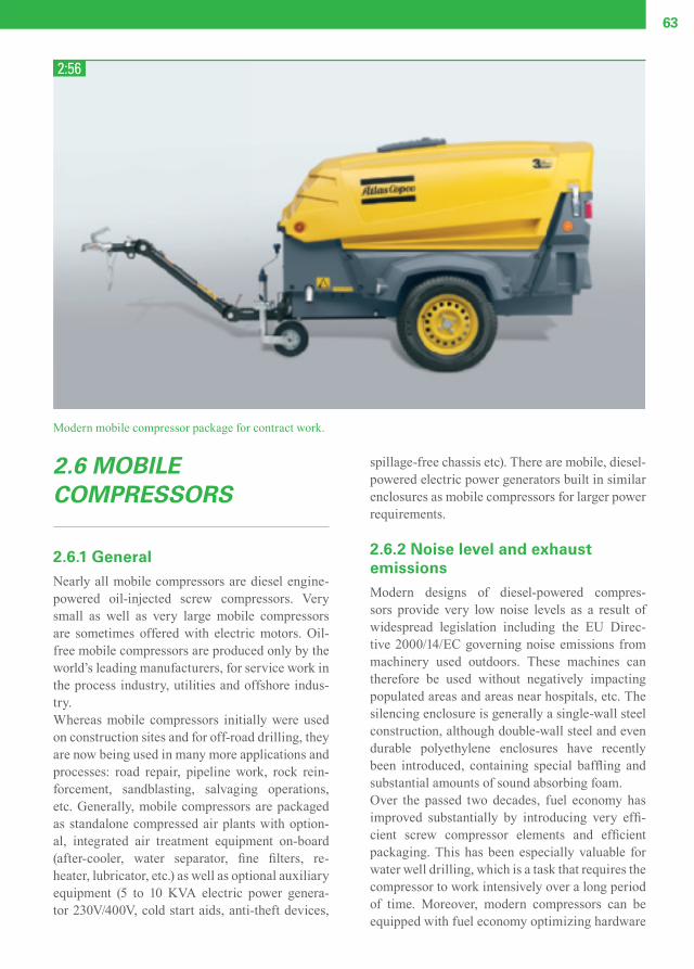
63
2:56
Modern mobile compressor package for contract work.
2.6 MOBILE COMPRESSORS
2.6.1 GeneralNearly all mobile compressors are diesel engine-powered oil-injected screw compressors. Very small as well as very large mobile compressors are sometimes offered with electric motors. Oil-free mobile compressors are produced only by the world’s leading manufacturers, for service work in the process industry, utilities and offshore indus-try.Whereas mobile compressors initially were used on construction sites and for off-road drilling, they are now being used in many more applications and processes: road repair, pipeline work, rock rein-forcement, sandblasting, salvaging operations, etc. Generally, mobile compressors are packaged as standalone compressed air plants with option-al, integrated air treatment equipment on-board (after-cooler, water separator, fi ne fi lters, re-heater, lubricator, etc.) as well as optional auxiliary equipment (5 to 10 KVA electric power genera-tor 230V/400V, cold start aids, anti-theft devices,
spillage-free chassis etc). There are mobile, diesel-powered electric power generators built in similar enclosures as mobile compressors for larger power requirements.
2.6.2 Noise level and exhaust emissionsModern designs of diesel-powered compres-sors provide very low noise levels as a result of widespread legislation including the EU Direc-tive 2000/14/EC governing noise emissions from machinery used outdoors. These machines can therefore be used without negatively impacting populated areas and areas near hospitals, etc. The silencing enclosure is generally a single-wall steel construction, although double-wall steel and even durable polyethylene enclosures have recently been introduced, containing special baffl ing and substantial amounts of sound absorbing foam. Over the passed two decades, fuel economy has improved substantially by introducing very effi -cient screw compressor elements and effi cient packaging. This has been especially valuable for water well drilling, which is a task that requires the compressor to work intensively over a long period of time. Moreover, modern compressors can be equipped with fuel economy optimizing hardware
CAM_edition8_2014.indd 63 13/04/15 14:52
64
and software that is far superior to the convention-al pneumatic engine/compressor control systems, for example FuelXpert and DrillAirXpert.Since the introduction of specifi c exhaust emission legislation in 1997 in the United States, Europe and elsewhere, diesel engines that comply with latest exhaust gas emission requirements are being chosen more often: EURO III will be introduced between 2006-2013, EURO IV from 2014 on, and US Tier 4 between 2008 and 2015.
2.6.3 Operational fl exibilityWhereas stationary industrial compressors are installed to serve only one or a few applications along a common compressed air distribution sys-tem, modern mobile compressors must demon-strate high overall operational fl exibility to serve a multitude of applications in different environ-ments based on ambient temperatures, humidity levels, working pressures, altitudes and load cycle profi les. Other requirements relative to mobile compressors include high operating reliability, good service characteristics, small environmental impact resulting from low noise levels and regu-lated exhaust emission levels, compact dimensions and a low total weight.Operation in climates with medium to high humidity, in particular when the load/unload pro-fi le contains load cycles at high pressure or long periods of unload operation, will cause some of the atmosphere water content to condense inside the compressor oil circuit. This has a negative impact on the lubricated compressor components as well as on the oil itself. Having just 1% of water in the oil will reduce the useful life of the bearings by 40%. The most modern mobile compressors can be equipped with an electronic oil temperature control system to protect the compressor’s operat-ing life.
CAM_edition8_2014.indd 64 13/04/15 14:52

3DIMENSIONING AND SERVICING COMPRESSOR INSTALLATIONS
CAM_edition8_2014.indd 65 13/04/15 14:52

66
3.1 DIMENSIONING COMPRESSOR INSTALLATIONS
3.1.1 GeneralA number of decisions must be made when dimen-sioning a compressed air installation for it to suit the user’s needs, provide maximum operating economy and be prepared for future expansion.The foundation is the applications or process that will use the compressed air. Therefore, these must be mapped out as a starting point for all other dimensioning activities.
The areas that must be examined include the calcu-lation or assessment of the air requirement and the reserve capacity and the space for future expan-sion. The working pressure is a critical factor, as this signifi cantly impacts energy consumption. Sometimes it can be economical to use different compressors for different pressure ranges.The quality of the compressed air is not only a question of water content, but has increasingly become an environmental issue as well. Odor and the microorganism content are important factors that can affect the product quality, rejections, the working environment and the outdoor environ-ment. The issue of whether the compressor instal-lation should be centralized or decentralized may affect the fl oor space requirement and perhaps future expansion plans. From both a fi nancial and ecological point of view it is becoming increas-
ingly important to investigate the possibilities of recovering energy at an early stage for quick return on investment. It is important to analyze these types of issues with regard to current as well as future requirements. Only after doing so will it be possible to design an installation that offers suffi cient fl exibility.
3.1.1.1 Calculating the working pressureThe compressed air equipment in an installation determines the requisite working pressure. The correct working pressure does not just depend on the compressor, but also on the design of the compressed air system and its piping, valves, com-pressed air dryers, fi lters, etc.Different types of equipment can demand different pressures within the same system. Normally, the highest pressure determines the requisite instal-lation pressure and other equipment will be fi tted with pressure reducing valves at the point of con-sumption. In more extreme cases, the method can be uneconomical and a separate compressor for special needs can be a solution.It should also be kept in mind that the pressure drop quickly increases as fl ow increases. If a change in consumption can be expected, it makes economic sense to adapt the installation to these conditions.Filters and special dust fi lters, have a low initial pressure drop, but become clogged over time and are replaced at the recommended pressure drop. This factor will enter into the calculation. The compressor’s fl ow regulation also causes pressure variations and therefore must also be included in the assessment. It may be appropriate to perform calculations using the following example:
3:1
The air requirement for connected equipment is obtained from tool catalogues and production equipment data. By assess-ing the individual utilization factors one can determine upper and lower limits for the overall air demand.
CAM_edition8_2014.indd 66 13/04/15 14:52

67
Description Pressure drop bar
End user 6Final fi lter 0.1–0.5Pipe system 0.2Dust fi lter 0.1–0.5Dryer 0.1Compressor regulation range 0.5
Compressor max.working pressure 7.0–7.8
It is the primarily the end consumer application along with the pressure drop between the compres-sor and the consumer that determines the pressure the compressor will need to produce. The working pressure can be determined by adding the pres-sure drop to the system, as shown in the example above.
3.1.1.2 Calculating the air requirementThe nominal compressed air requirement is deter-mined by the individual air consumers. This is cal-culated as a sum of air consumption for all tools, machines and processes that will be connected, and estimating their individual utilization factor by experience. Additions for leakage, wear and future changes in the air requirement must also be taken into consideration from the outset. A simple method to estimate the present and future air requirement is to compile the air requirement for connected equipment and the utilization factor.
This type of calculation requires a list of machines and their respective air consumption data and expected utilization factors. If data is not available for the air consumption or utilization factor, stan-dard values from lists may be used. The utilization factor for tools can be diffi cult to estimate, there-fore calculation values should be compared with measured consumption in similar applications.For example, large air-powered consumers such as grinders and sandblasting machines are used fre-quently for long periods (3–10 minutes) at continu-ous operation, despite their low overall utilization factor. This cannot truly be characterized as inter-mittent operation, and it is necessary to estimate how many machines will be used simultaneously in order to estimate total air consumption.Compressor capacity is essentially determined by the total nominal compressed air requirement. The compressors’ free output fl ow rate should cover this rate of air consumption. The calculated reserve capacity is primarily determined by the cost of lost production resulting from a potential compressed air failure.The number of compressors and their mutual size is determined principally by the required degree of fl exibility, control system and energy effi ciency. In an installation in which only one compressor sup-plies compressed air (due to cost restrictions), the system can be prepared for quick connection of a portable compressor as part of servicing. An older compressor used as a reserve source, can be used as inexpensive reserve power.
3:2
Method of operation analysis.
CAM_edition8_2014.indd 67 13/04/15 14:52

68
3.1.1.3 Measuring the air requirementAn operating analysis provides key factors about the compressed air requirement and forms the basis for assessing the optimal amount of com-pressed air to produce. Most industrial companies are constantly evolving, and this means that their compressed air requirements also change. It is therefore important that the compressed air supply be based on the current prevailing conditions, and an appropriate margin for expansion be built into the installation.
An operating analysis entails measuring operat-ing data, which is possibly supplemented with the inspection of an existing compressed air installa-tion over a suitable period of time. This analysis should cover at least one week of operations and the measurement period should be selected with care to allow it to represent a typical case and pro-vide relevant data. The stored data also provides an opportunity to simulate different measures and changes in compressor operations and to analyze
the impact on the installation’s overall economy.Factors such as loading times and off-loading times also enter into the total assessment of compressor operations. These provide the basis for assessing the loading factor and the compressed air require-ment, spread over a day or a work week. Accord-ingly, the loading factor cannot just be read off of the compressor’s running hour meter.An operating analysis also gives a basis for poten-tial energy recovery. Frequently, more than 90% of the energy supplied can be recovered. Further-more, the analysis can provide answers relating to dimensioning as well as the operating method for installation. For example, the working pressure can often be reduced at certain times and the control system can be modifi ed in order to improve com-pressor usage with changes in production. It is also fundamentally important to check for leakage.For the production of small quantities of air dur-ing the night and weekends, you must consider whether it is worth installing a smaller compressor to cover this requirement.
3:3
During an operation analysis the compressed air production is continuously measured for a full week.
CAM_edition8_2014.indd 68 13/04/15 14:52

69
3.1.2 Centralization or decentralization
3.1.2.1 GeneralThere are several factors that infl uence the choice between one large centralized or several smaller decentralized compressors to meet a given com-pressed air requirement. Factors that are taken into consideration include the cost of a production shut-down, guaranteed availability of electrical power, loading variations, costs for the compressed air system and the available fl oor space.
3.1.2.2 Centralized compressor installationsA centralized compressor installation is in many cases the solution of choice, as it is less expen-sive to run and maintain than several, locally dis-tributed compressors. Compressor plants can be effi ciently interconnected, thereby resulting in lower energy consumption. A central installation also involves lower monitoring and maintenance costs as well as better opportunities for recover-ing energy. The overall fl oor area required for the compressor installation is also minimized. Filters, coolers and other auxiliary equipment and the common air intake can be optimally dimensioned. Noise reduction measures will also be easier to fi t.A system comprising several, different sized com-pressors in a central installation can be sequence controlled to improve effi ciency. One large com-pressor may have more diffi culty meeting large variations in the compressed air requirement with-out losing effi ciency.
For example, systems with one large compressor are often supplemented with a smaller compressor for use during periods such as a night shift or on weekends. Another factor worth considering is the impact that starting a large electric motor has on the mains supply.
3.1.2.3 Decentralized compressor installationsA system with several decentralized compressors can also be the preferred choice for certain appli-cations. It involves a smaller, simpler compressed air distribution system. A disadvantage of decen-tralized compressors lies in the diffi culty of inter-regulating the compressed air supply and in main-taining a reserve capacity. Modern compressors with fully-integrated compressed air condition-ing equipment (dryers, fi lters etc.) and with high-performance silencing measures can be installed at the worksite, thus reducing compressed air distribution costs and eliminating the need for a separate building or an extension to the separate compressor room.Decentralized compressors can be utilized to main-tain the pressure in a system with a large pressure drop if the intermediate processes temporarily draw too much air. An alternative with extremely short peaks of air consumption is to solve the prob-lem by positioning buffers (air receiver) in strate-gic locations. A unit or building normally supplied from a com-pressed air plant and which is the sole consumer of compressed air during specifi c periods can be sec-tioned off and supplied with its own decentralized compressor. The advantage of this layout is that it avoids “feeding” any leakage in the remaining part of the system and that the localized compressor may be adapted to the smaller requirement.
3.1.3 Dimensioning at high altitude
3.1.3.1 GeneralBoth the ambient pressure and temperature decrease with altitude above sea level. This lower inlet pressure impacts the pressure ratio, for the compressors as well as for the connected equip-ment, which, in practice, signifi es an impact on both power consumption and air consumption. At the same time, the changes due to higher altitude
3:4
Even small leakages can result in large costs and down-time.
CAM_edition8_2014.indd 69 13/04/15 14:52

70
will also affect the available rated power from electric motors and from combustion engines.The way in which ambient conditions infl uence the end consumer application must also be taken into account. Is a specifi c mass fl ow rate (in a process) or a volume fl ow rate required? Was the pressure ratio, absolute pressure or gauge pressure used for dimensioning? Is the compressed air temperature signifi cant? All of these considerations create different condi-tions for dimensioning a compressed air installa-tion installed at a high altitude and can be fairly complex to calculate. If anything is unclear or for any questions, the installer should always contact the equipment manufacturer.
3.1.3.2 The effect on a compressorTo choose the correct compressor where the ambi-ent conditions differ from those stated on the data sheet, the following factors should be taken into consideration:
- Height above sea level or ambient pressure - Ambient temperature - Humidity - Coolant temperature - Type of compressor - Power source
These factors primarily affect the following:
- Max. working pressure - Capacity - Power consumption - Cooling requirement
3:5
3:6
The table shows the standardized pressure and tempera-ture at different altitudes. The pressure is also depen-dent on the weather and varies approx. ± 5%, while the local season dependent temperature variations can be considerable.
Altitude effect on the compressor at 7 bar(e) working pressure and constant ambient temperature. Bear in mind that each compressor type has a maximum pressure ratio that can not be exceeded.
(a)
Reduction per 1000m altitude increase
Free Air DeliveryFAD%
Mass air flow%Normal air flow%
CAM_edition8_2014.indd 70 13/04/15 14:52

71
The most important factor is the inlet pressure variations at altitude. A compressor with a pres-sure ratio of 8.0 at sea level will have a pressure ratio of 11.1 at an altitude of 3000 meters (pro-vided that the application’s operating pressure is unchanged). This affects the effi ciency and, con-sequently, the power requirement. The amount of change is dependent on the type of compressor and the design, as detailed in Figure 3:6. The ambient temperature, humidity and coolant temperature all interact and affect the compressor performance to different degrees on single-stage or multi-stage compressors, dynamic compressors or displacement compressors.
3.1.3.3 Power source3.1.3.3.1 Dimensioning electric motorsCooling is impaired on electric motors by the low-er density air at high altitudes. Standard motors should be able to work up to 1000 m and with an ambient temperature of 40°C without any impacts on rated data. At higher altitudes, Table 3:7 can be used as a guide for standard motor performance deration. Note that for some compressor types, the electric motor performance is impaired more
than the compressor requisite shaft power at high altitude. Therefore, operating a standard compres-sor at high altitude requires lowering the working pressure or else fi tting an oversized motor.
3.1.3.3.2 Dimensioning IC enginesA reduction in ambient pressure, temperature increase or reduction in humidity reduces the oxygen content in the air used for combustion and, consequently, the extractable power from the internal combustion (IC) engine. The degree of shaft power de-ration depends on the type of engine and its breathing method (naturally aspi-rated or turbocharged) as set out in Figure 3:8. The humidity plays a smaller role (de-ration <1% per 1000 m) when the temperature falls below 30°C.Note that the engine power falls more rapidly than the compressor requisite shaft power. This implies that for each compressor/engine combina-tion, there is a maximum working height that will use the entire power margin of the engine over the compressor for use at sea level. Generally, suppli-ers should be entrusted with calculating and stat-ing the specifi c data that applies to the compressor, engine and air consumption equipment in question.
3:8
3:7
Available combustion engine power in function of altitude and temperature.
Permitted load in % of the electric motor’s rated power.
Naturally aspirated engine
Turbocharged engine
CAM_edition8_2014.indd 71 13/04/15 14:52

72
3.2 AIR TREATMENT
3.2.1 GeneralIt is vitally important to the user that the com-pressed air be of the right quality. If air that con-tains contamination comes into contact with the fi nal product, rejection costs can quickly become unacceptably high and the cheapest solution can quickly become the most expensive. It is impor-tant that you select the compressed air quality in line with the company’s quality policy and even attempt to judge future requirements.Compressed air can contain unwanted substances, for example, water in drop or vapor form, oil in drop or aerosol form, as well as dust. Depending on the compressed air’s application area, these substances can impair production results and even increase costs. The purpose of air treatment is to produce the compressed air quality specifi ed by the consumer.When the role of compressed air in a process is
clearly defi ned, fi nding the system that will be the most profi table and effi cient in that specifi c situ-ation is simple. It is a question, among others, of establishing whether the compressed air will come into direct contact with the product or whether, for example, oil mist can be accepted in the working environment. A systematic method is required to select the right equipment.
3.2.2 Water vapor in compressed airAir in the atmosphere always contains moisture in the form of water vapor. Some water vapor is included in the compressed air and can potentially cause problems. Examples include: high mainte-nance costs, shortened service life and impaired tool performance, high rate of rejection with spray painting and plastic injection, increased leakage, disturbances in the control system and instru-ments, shorter service life for the pipe system due to corrosion and more expensive installation. The water can be separated using accessories: after-coolers, condensation separators, refrigerant dry-ers and adsorption dryers.
3:9
The main components in a typical compressed air system installation. The air treatment equipment determines the qual-ity of the compressed air, which may have an effect on the economy of the installation.
CAM_edition8_2014.indd 72 13/04/15 14:52
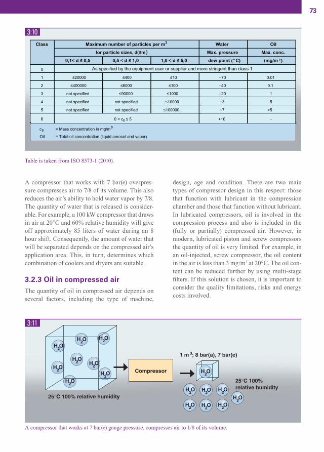
73
A compressor that works with 7 bar(e) overpres-sure compresses air to 7/8 of its volume. This also reduces the air’s ability to hold water vapor by 7/8. The quantity of water that is released is consider-able. For example, a 100 kW compressor that draws in air at 20°C and 60% relative humidity will give off approximately 85 liters of water during an 8 hour shift. Consequently, the amount of water that will be separated depends on the compressed air’s application area. This, in turn, determines which combination of coolers and dryers are suitable.
3.2.3 Oil in compressed airThe quantity of oil in compressed air depends on several factors, including the type of machine,
design, age and condition. There are two main types of compressor design in this respect: those that function with lubricant in the compression chamber and those that function without lubricant. In lubricated compressors, oil is involved in the compression process and also is included in the (fully or partially) compressed air. However, in modern, lubricated piston and screw compressors the quantity of oil is very limited. For example, in an oil-injected, screw compressor, the oil content in the air is less than 3 mg/m3 at 20°C. The oil con-tent can be reduced further by using multi-stage fi lters. If this solution is chosen, it is important to consider the quality limitations, risks and energy costs involved.
3:10
3:11
A compressor that works at 7 bar(e) gauge pressure, compresses air to 1/8 of its volume.
Table is taken from ISO 8573-1 (2010).
CAM_edition8_2014.indd 73 13/04/15 14:52
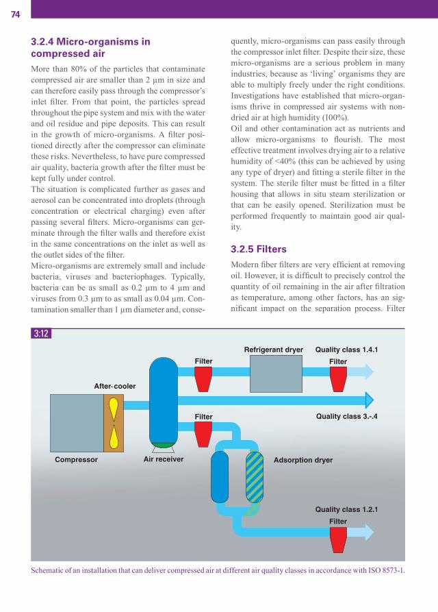
74
3.2.4 Micro-organisms in compressed airMore than 80% of the particles that contaminate compressed air are smaller than 2 µm in size and can therefore easily pass through the compressor’s inlet fi lter. From that point, the particles spread throughout the pipe system and mix with the water and oil residue and pipe deposits. This can result in the growth of micro-organisms. A fi lter posi-tioned directly after the compressor can eliminate these risks. Nevertheless, to have pure compressed air quality, bacteria growth after the fi lter must be kept fully under control.The situation is complicated further as gases and aerosol can be concentrated into droplets (through concentration or electrical charging) even after passing several fi lters. Micro-organisms can ger-minate through the fi lter walls and therefore exist in the same concentrations on the inlet as well as the outlet sides of the fi lter.Micro-organisms are extremely small and include bacteria, viruses and bacteriophages. Typically, bacteria can be as small as 0.2 µm to 4 µm and viruses from 0.3 µm to as small as 0.04 µm. Con-tamination smaller than 1 µm diameter and, conse-
quently, micro-organisms can pass easily through the compressor inlet fi lter. Despite their size, these micro-organisms are a serious problem in many industries, because as ‘living’ organisms they are able to multiply freely under the right conditions. Investigations have established that micro-organ-isms thrive in compressed air systems with non-dried air at high humidity (100%).Oil and other contamination act as nutrients and allow micro-organisms to fl ourish. The most effective treatment involves drying air to a relative humidity of <40% (this can be achieved by using any type of dryer) and fi tting a sterile fi lter in the system. The sterile fi lter must be fi tted in a fi lter housing that allows in situ steam sterilization or that can be easily opened. Sterilization must be performed frequently to maintain good air qual-ity.
3.2.5 FiltersModern fi ber fi lters are very effi cient at removing oil. However, it is diffi cult to precisely control the quantity of oil remaining in the air after fi ltration as temperature, among other factors, has an sig-nifi cant impact on the separation process. Filter
3:12
Schematic of an installation that can deliver compressed air at different air quality classes in accordance with ISO 8573-1.
CAM_edition8_2014.indd 74 13/04/15 14:52
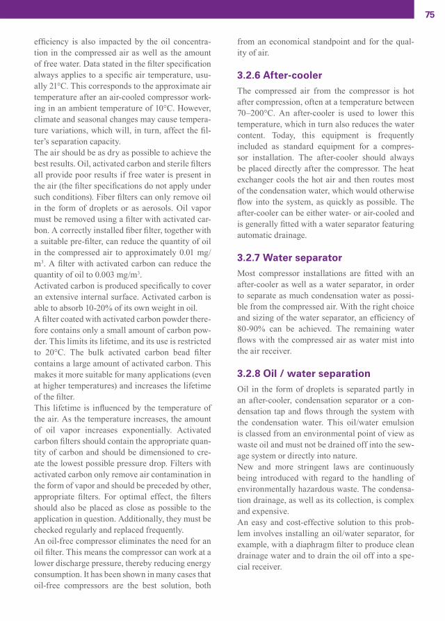
75
efficiency is also impacted by the oil concentra-tion in the compressed air as well as the amount of free water. Data stated in the filter specification always applies to a specific air temperature, usu-ally 21°C. This corresponds to the approximate air temperature after an air-cooled compressor work-ing in an ambient temperature of 10°C. However, climate and seasonal changes may cause tempera-ture variations, which will, in turn, affect the fil-ter’s separation capacity.The air should be as dry as possible to achieve the best results. Oil, activated carbon and sterile filters all provide poor results if free water is present in the air (the filter specifications do not apply under such conditions). Fiber filters can only remove oil in the form of droplets or as aerosols. Oil vapor must be removed using a filter with activated car-bon. A correctly installed fiber filter, together with a suitable pre-filter, can reduce the quantity of oil in the compressed air to approximately 0.01 mg/m3. A filter with activated carbon can reduce the quantity of oil to 0.003 mg/m3.Activated carbon is produced specifically to cover an extensive internal surface. Activated carbon is able to absorb 10-20% of its own weight in oil. A filter coated with activated carbon powder there-fore contains only a small amount of carbon pow-der. This limits its lifetime, and its use is restricted to 20°C. The bulk activated carbon bead filter contains a large amount of activated carbon. This makes it more suitable for many applications (even at higher temperatures) and increases the lifetime of the filter.This lifetime is influenced by the temperature of the air. As the temperature increases, the amount of oil vapor increases exponentially. Activated carbon filters should contain the appropriate quan-tity of carbon and should be dimensioned to cre-ate the lowest possible pressure drop. Filters with activated carbon only remove air contamination in the form of vapor and should be preceded by other, appropriate filters. For optimal effect, the filters should also be placed as close as possible to the application in question. Additionally, they must be checked regularly and replaced frequently.An oil-free compressor eliminates the need for an oil filter. This means the compressor can work at a lower discharge pressure, thereby reducing energy consumption. It has been shown in many cases that oil-free compressors are the best solution, both
from an economical standpoint and for the qual-ity of air.
3.2.6 After-coolerThe compressed air from the compressor is hot after compression, often at a temperature between 70–200°C. An after-cooler is used to lower this temperature, which in turn also reduces the water content. Today, this equipment is frequently included as standard equipment for a compres-sor installation. The after-cooler should always be placed directly after the compressor. The heat exchanger cools the hot air and then routes most of the condensation water, which would otherwise flow into the system, as quickly as possible. The after-cooler can be either water- or air-cooled and is generally fitted with a water separator featuring automatic drainage.
3.2.7 Water separatorMost compressor installations are fitted with an after-cooler as well as a water separator, in order to separate as much condensation water as possi-ble from the compressed air. With the right choice and sizing of the water separator, an efficiency of 80-90% can be achieved. The remaining water flows with the compressed air as water mist into the air receiver.
3.2.8 Oil / water separationOil in the form of droplets is separated partly in an after-cooler, condensation separator or a con-densation tap and flows through the system with the condensation water. This oil/water emulsion is classed from an environmental point of view as waste oil and must not be drained off into the sew-age system or directly into nature. New and more stringent laws are continuously being introduced with regard to the handling of environmentally hazardous waste. The condensa-tion drainage, as well as its collection, is complex and expensive. An easy and cost-effective solution to this prob-lem involves installing an oil/water separator, for example, with a diaphragm filter to produce clean drainage water and to drain the oil off into a spe-cial receiver.
CAM_edition8_2014.indd 75 13/04/15 14:52
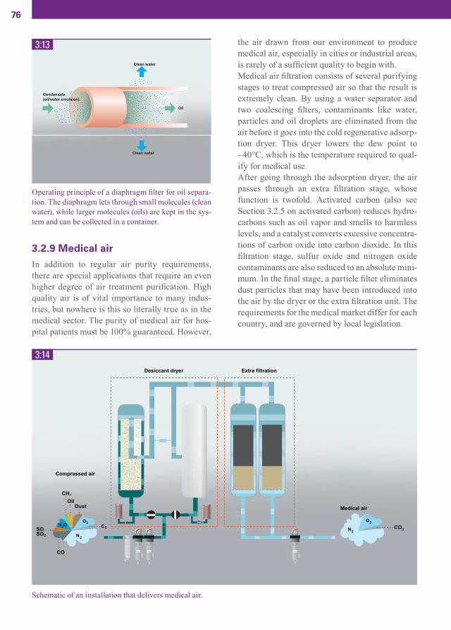
76
3.2.9 Medical airIn addition to regular air purity requirements, there are special applications that require an even higher degree of air treatment purifi cation. High quality air is of vital importance to many indus-tries, but nowhere is this so literally true as in the medical sector. The purity of medical air for hos-pital patients must be 100% guaranteed. However,
the air drawn from our environment to produce medical air, especially in cities or industrial areas, is rarely of a suffi cient quality to begin with.Medical air fi ltration consists of several purifying stages to treat compressed air so that the result is extremely clean. By using a water separator and two coalescing fi lters, contaminants like water, particles and oil droplets are eliminated from the air before it goes into the cold regenerative adsorp-tion dryer. This dryer lowers the dew point to –40°C, which is the temperature required to qual-ify for medical use. After going through the adsorption dryer, the air passes through an extra fi ltration stage, whose function is twofold. Activated carbon (also see Section 3.2.5 on activated carbon) reduces hydro-carbons such as oil vapor and smells to harmless levels, and a catalyst converts excessive concentra-tions of carbon oxide into carbon dioxide. In this fi ltration stage, sulfur oxide and nitrogen oxide contaminants are also reduced to an absolute mini-mum. In the fi nal stage, a particle fi lter eliminates dust particles that may have been introduced into the air by the dryer or the extra fi ltration unit. The requirements for the medical market differ for each country, and are governed by local legislation.
3:13
3:14
Operating principle of a diaphragm fi lter for oil separa-tion. The diaphragm lets through small molecules (clean water), while larger molecules (oils) are kept in the sys-tem and can be collected in a container.
Schematic of an installation that delivers medical air.
CAM_edition8_2014.indd 76 13/04/15 14:52

77
3.3 COOLING SYSTEM
3.3.1 Water-cooled compressors
3.3.1.1 GeneralThe more compressed air is cooled inside a com-pressor’s inter-cooler and after-cooler, the more energy-effi cient the compressor will be and the more the water vapor will be condensed. A water-cooled compressor installation puts little demand on the compressor room ventilation system, as the cooling water contains, in the form of heat, approximately 90% of the energy taken up by the electric motor.Compressor water cooling systems can be based on one of three main principles: open systems without circulating water (connected to an external water supply), open systems with circulating water (cooling tower), and closed systems with circulat-ing water (including an external heat exchanger/radiator).
3.3.1.2 Open system without circulating waterIn an open system without circulating water, water is supplied by an external source: municipal water mains, lake, stream, or well and after passing
through the compressor, this water is discharged as wastewater. The system should be controlled by a thermostat, to maintain the desired air tempera-ture as well as to govern water consumption. Generally, an open system is easy and inexpensive to install, but expensive to run, especially if the cooling water is taken from the municipal water mains. Water from a lake or stream is normally free of charge, but must be fi ltered and purifi ed to limit the risk of clogging the cooling system. Fur-thermore, water that is rich in lime can result in boiler scale forming inside the coolers, and caus-ing gradually impaired cooling. The same applies to salt water, which may however be used if the system is designed properly and dimensioned accordingly.
3.3.1.3 Open system with circulating waterIn an open system with circulating water, cooling water from the compressor is re-cooled in an open cooling tower. Water is cooled in the cooling tower by allowing it to sprinkle down into a chamber as surrounding air is blown through. As a result, part of the water evaporates and the remaining water is cooled to 2˚C below the ambient temperature (this may vary depending on the temperature and rela-tive humidity).
3:15
Open cooling system with circulating cooling water.
CAM_edition8_2014.indd 77 13/04/15 14:52

78
Open systems with circulating water are primar-ily used when the availability of an external water supply is limited. The disadvantage to this system is that the water gradually becomes contaminated by the surrounding air. The system must be con-tinuously diluted using external water due to evap-oration. Dissolvable salts are deposited on the hot metal surfaces, reducing the thermal heat transfer capacity of the cooling tower. The water must be regularly analyzed and treated with chemicals to avoid algae growth in the water. During winter, when the compressor is not operating, the cooling tower must either be drained or the water must be heated to prevent freezing.
3.3.1.4 Closed systemIn a closed cooling system, the same water con-tinuously circulates between the compressor and some form of external heat exchanger. This heat exchanger is in turn cooled either by means of an external water circuit or by the surrounding air. When the water is cooled using another water cir-cuit, a fl at plate heat exchanger is used.
required. The closed cooling water system is fi lled with pure, softened water. When glycol is added, the compressor system’s water fl ow must be recal-culated, as the type and concentration of glycol affects the water’s thermal capacity and viscosity. It is also important that the entire system be thor-oughly cleaned before being fi lled for the fi rst time. A correctly implemented closed water sys-tem requires very little supervision and has low maintenance costs. For installations in which the available cooling water is potentially corrosive, the cooler should be designed in a corrosion-resistant material such as Incoloy.
3.3.2 Air cooled compressorsMost modern compressor packages are also avail-able in an air-cooled version, whereby the forced
3:16
3:17
3:18Illustration of a fl at heat exchanger. Flat heat exchangers are easy to clean, which makes it possible to indirectly cool the compressor using lake water or stream water.
A basic air heater (air cooled heat exchanger) can be found in closed cooling systems for cooling liquids such as water/glycol, oil, etc. In aggressive environments or with aggressive liquids stainless steel or titanium cool-ers are used.
The water must be protected from freezing at low tem-peratures. Remember that the size of the cooler may need to be increased as, for example, a water/glycol mix-ture has a lower thermal capacity than pure water.
When the water is cooled using the surrounding air, a cooling matrix consisting of pipes and cool-ing fi ns is used. The surrounding air is forced to circulate through the pipes and fi ns by means of one or more fans. This method is suitable if the availability of cooling water is limited. The cool-ing capacity of open or closed circuits is about the same, i.e. the compressor water is cooled to 5°C above the coolant temperature.If the cooling water is cooled by the surrounding air, the addition of an anti-freeze (e.g. glycol) is
kJ/kg x K
Specific heat
CAM_edition8_2014.indd 78 13/04/15 14:52

79
ventilation inside the air compressor package con-tains close to 100% of the energy consumed by the electric motor.
3.4 ENERGY RECOVERY
3.4.1 GeneralWhen air is compressed heat is formed. Before the compressed air is distributed into the pipe system the heat energy is extracted, and becomes waste heat. For each compressed air installation, the issue of suffi cient and reliable cooling capacity for the installation must be addressed. Cooling can take place either by means of the outdoor air or a cooling water system that uses municipal water, stream water or process water in an open or closed system.Many installations that produce compressed air offer signifi cant and frequently unutilized energy saving possibilities in the form of waste energy recovery. In large industries, energy costs can
amount to 80% of the total cost of compressed air production. As much as 94% of the energy supplied to the compressor can be recovered, for example, as 90° hot water from oil-free screw compressors. This fact illustrates that saving measures quickly provide substantial return.A compressor central plant in a large industry that consumes 500 kW over 8,000 operating hours per year represents a yearly energy consumption of 4 million kWh. The possibilities for recovering sub-stantial amounts of waste heat via hot air or hot water are real.The return on investment for energy recovery is usually as short as 1–3 years. In addition, energy recovered by means of a closed cooling system enhances compressor operating conditions, reli-ability and service life due to an equalized tem-perature level and high cooling water quality, to name but a few advantages. Nordic countries are somewhat of a forerunner in this arena and energy recovery has been standard practice for quite some time now for compressor installations.Most medium to large compressors from the major suppliers are now adapted for fi tting with standard equipment for waste heat recovery.
3:19
Schematic of a closed cooling system. The heat exchanger can be water cooled or air cooled.
CAM_edition8_2014.indd 79 13/04/15 14:52

80
3:20
3:21
As heat is the unavoidable by-product of compression, energy can be recovered in the form of hot water from the com-pressor cooling system.
Diagram illustrating some of the typical application areas for energy recovery from the compressor cooling water. At the highest temperature levels the degree of recovery is the greatest.
CAM_edition8_2014.indd 80 13/04/15 14:53

81
3.4.2 Calculation of the recovery potential
The laws of physics dictate that nearly all energy supplied to a compressor installation is converted into heat. The more energy that can be recovered and utilized in other processes, the higher the sys-tem’s overall effi ciency. The quantity of heat that can be recovered can be calculated by the equa-tion:
Recovered energy in kWh/year:
Savings per year: (€) TR = Time of recovered energy demand (hrs/year)K1 = Part of TR with loaded compressor (hrs/year)K2 = Part of TR with off-loaded compressor (hrs/year
Q1 = Available coolant power with loaded compressor (kW)Q2 = Available coolant power with off-loaded compressor (kW)ep = Energy price level (€/kWh)η = Normal heat source effi ciency (%)
In many cases the degree of heat recovery can exceed 90% if the energy gained by cooling the compressor installation can be utilized effi ciently. The function of the cooling system, the distance to the point of consumption, and the degree and continuity of the heat requirement are all decisive factors.With large thermal fl ows, selling the recovered heat energy is a possibility that should not be ignored. The electrical energy supplier could be a potential customer, and investment, sub-order and delivery could readily be negotiated. An opportu-nity for savings also exists by coordinating energy recovery from several processes.
3:22
Each compressor installation has a large potential for energy recovery. Up to 95% of the supplied energy can be recovered from large, oil-free screw compressors.
CAM_edition8_2014.indd 81 13/04/15 14:53

82
3.4.3 Recovery methods
3.4.3.1 GeneralEnergy recovery from compressed air installations does not always result in heat when it is required and oftentimes, not in suffi cient quantities. The quantity of recovered energy will vary over time if the compressor has a variable load. In order for recovery to be feasible, a corresponding relatively stable heat energy demand is needed. Recovered waste heat energy is best utilized to supplement energy supplied to the system, so that the available energy is always utilized when the compressor is operating.
3.4.3.2 Air-cooled systemOptions for air-cooled compressors, which pro-duce a high hot air fl ow rate at a relatively low temperature, are direct building heating or heat
exchanging to a preheating battery. The heated cooling air is then distributed using a fan.
When buildings do not require additional heat, the hot air is evacuated into the atmosphere, either automatically by thermostat control or manually by controlling the air damper. A limiting factor is the distance between the compressors and the building that needs to be heated. This distance should be limited (preferably the distance between adjoining buildings). Furthermore, the possibility of recovery may be limited to the colder periods of the year. Air-borne energy recovery is more com-mon for small- and medium-sized compressors. Recovery of waste heat from compressor air cool-ing systems results in only small losses from the distribution and requires little investment.
3.4.3.3 Water-cooled systemThe cooling water from a water-cooled compres-sor with a temperature up to 90° can supplement a hot water heating system. If the hot water is used instead for washing, cleaning or showering, a nor-mal base load hot water boiler is still required. The energy recovered from the compressed air system forms a supplementary heat source that reduces the load on the boiler, saves heating fuel and could potentially result in the use of a smaller boiler.
3:23
3:24Example of recovery potential of compressors.
Energy recovery from an air-cooled compressor.
Prerequisites for energy recovery from compressed air compressors differ in part depending on the type of compressor. Standard oil-free compres-sors are easy to modify for energy recovery. This type of compressor is ideal for integration in a hot water heating system since it provides the water temperature (90°C) required for effi cient energy recovery. On oil-lubricated compressors, the oil,
CAM_edition8_2014.indd 82 13/04/15 14:53

83
3:25
3:26
Example of water-borne energy recovery of an oil-free screw compressor.
Example of water-borne energy recovery of an oil lubricated screw compressor. The residue cooler with regulation sys-tem is integrated in the compressor.
CAM_edition8_2014.indd 83 13/04/15 14:53

84
which takes part in the compression process, is a factor that limits the possibilities for high cooling water temperatures.In centrifugal compressors, the temperature levels are generally lower because of the lower pressure ratio per compression stage, thereby limiting the degree of recovery.
Waterborne waste energy recovery is best suited to compressors with electric motor power over 10 kW. Waterborne recovery of waste energy requires a more complex installation than airborne waste energy recovery. The basic equipment consists of fluid pumps, heat exchangers and regulation valves.Heat can also be distributed to remote buildings using relatively small pipe diameters (40-80 mm) without significant heat losses using waterborne energy recovery. The high initial water tem-perature means that waste energy can be used to increase the temperature of the return water from a hot water boiler. Therefore, the normal heating source can be periodically switched off and be replaced by the compressor’s waste heat recov-ery system. Waste heat from compressors in the process industry can also be used to increase the temperature of the process. It is also possible to use air-cooled oil-lubricated screw compressors to apply water-borne waste energy recovery. This requires a heat exchanger in the oil circuit, and the system will provide water at lower temperatures (50° - 60°) than with oil-free compressors.
3.5 THE COMPRESSOR ROOM
3.5.1 GeneralNot so long ago, acquiring a compressor required the customer to purchase the electric motor, starter equipment, after-cooler, intake filters, etc. The customer also had to thoroughly examine capacity and quality demands with all of the various com-ponent suppliers. This was in order to ensure that all equipment was compatible with the compressor. Today, a compressor and all of its accessories are
purchased as a turnkey solution, and quite often as a fully-integrated package. A compressor package consists of a box frame, on which the compressor and accessories are mounted. All internal connec-tions between the different parts are factory-made. The complete compressor package is enclosed in a sound reducing enclosure to reduce noise levels.This has resulted in significantly simplifying installation. An extreme example is the so-called ‘worksite compressor’, which incorporates fully-integrated compressed air conditioning systems (dryer, filter, condensate remover etc.) and highly effective noise and vibration reduction measures. These modern compressor packages are installed along the existing compressed air distribution sys-tem or along future expansions thereof. Regardless, it is important to remember that the installation method may still have a significant influence on compressor system performance and reliability.
The main rule for an installation is first and fore-most to arrange a separate compressor central plant. Experience dictates that centralization is preferable, regardless of industry. Among other things, it provides improved operating economy, a better-designed compressed air system, service and user friendliness, protection against unauthor-ized access, proper noise control and simpler pos-sibilities for controlled ventilation.Secondly, a separate area in a building that is used for other purposes can be used for the compres-sor installation. Certain risks and inconveniences should be accounted for with this type of installa-tion, for example: disturbance due to noise or the compressor’s ventilation requirements, physical risks and/or overheating risks, drainage for con-densation, hazardous surroundings e.g. dust or inflammable substances, aggressive substances in the air, space requirements for future expansion and accessibility for service. However, installa-tion in a workshop or warehouse can facilitate the installations for energy recovery. If there are no facilities available for installing the compressor indoors, it may also be installed outdoors, under a roof. In this case, certain issues must be taken into consideration: the risk of freezing for conden-sation pockets and discharges, rain and snow pro-tection for the air intake opening, suction inlet and ventilation, required solid, flat foundation (asphalt, concrete slab or a flattened bed of shingle), the risk
CAM_edition8_2014.indd 84 13/04/15 14:53

85
of dust, infl ammable or aggressive substances and protection against unauthorized access.
3.5.2 Placement and designThe compressed air plant should be installed to facilitate distribution system routing in large installations with long piping. Service and main-tenance can be facilitated by installing the com-pressed air plant near auxiliary equipment such as pumps and fans; even a location close to the boiler room may be benefi cial.The building should feature lifting equipment that is dimensioned to handle the heaviest components in the compressor installation, (usually the electric motor) and/or have access to a forklift truck. It should also have suffi cient fl oor space for installa-tion of an extra compressor for future expansion.In addition, clearance height must be suffi cient to allow an electric motor or similar to be hoisted, should the need arise. The compressed air plant should have a fl oor drain or other facilities to handle condensation from the compressor, after-cooler, air receiver, dryers etc. The fl oor drain must be implemented in compliance with munici-pal legislation.
3.5.3 FoundationNormally only a fl at fl oor of suffi cient weight capacity is required to set up the compressor plant. In most cases, anti-vibration features are integrat-ed in the plant. For new installations, a plinth is usually used for each compressor package in order to allow the fl oor to be cleaned.Large piston and centrifugal compressors can require a concrete slab foundation, which is anchored to the bedrock or on a solid soil base. The impact of externally-produced vibration has been reduced to a minimum for advanced, com-plete compressor plants. In systems with centrifu-gal compressors, it may be necessary to vibration dampen the compressor room’s foundation.
3.5.4 Intake airThe compressor’s intake air must be clean and free of solid and gaseous contamination. Particles of dirt that cause wear and corrosive gases can be particularly damaging.The compressor air inlet is usually located at an opening in the sound-reducing enclosure, but can also be placed remotely, in a place in which the air is as clean as possible. Gas contamination
3:27
Installation in a compressor room is straightforward. The compressor package is a turnkey solution ready to install and connect to requisite auxiliary equipment.
CAM_edition8_2014.indd 85 13/04/15 14:53

86
from vehicle exhaust fumes can be fatal if mixed with air that is meant to be inhaled. A pre-fi lter (cyclone, panel or rotary band fi lter) should be used on installations where the surrounding air has a high dust concentration. In such cases, the pressure drop caused by the pre-fi lter must be accounted for during design.
It is also benefi cial for the intake air to be cold. It may therefore be appropriate to route this air through a separate pipe from the outside of the building into the compressor. It is important that corrosion-resistant pipes, fi tted with mesh over the inlet and designed so that there is no risk of drawing snow or rain into the com-pressor, be used for this purpose. It is also impor-tant to use pipes of a suffi ciently large diameter to have as low a pressure drop as possible.The design of the inlet pipes on piston compres-sors is particularly critical. Pipe resonance from acoustic standing waves caused by the compres-sor’s cyclic pulsating frequency can damage the piping as well as the compressor, cause vibration and affect the surroundings through irritating low frequency noise.
3.5.5 Compressor room ventilationHeat in the compressor room is generated from all compressors. This heat is let off by ventilating the compressor room. The quantity of ventilation air is determined by the size of the compressor and whether it is air- or water-cooled.The ventilation air for air-cooled compressors con-tains close to 100% of the energy consumed by the
It is important that the compressor installation has a layout that is service friendly and fl exible to accommodate future expansion. The minimum area at service points in front of the machine electrical cabinets should be 1200 mm.
Basic ventilation solution. The disadvantage is that ven-tilation is constant irrespective of the outside tempera-ture. In addition diffi culties can occur if two compres-sors are installed. The fans will be over-dimentioned if only one of the compressors is used. The problem can be solved by fi tting the fans with speed controlled motors, which start via a multi-stage thermostat.
3:28
3:29
CAM_edition8_2014.indd 86 13/04/15 14:53

87
System with several thermostat-controlled fans, which together can handle the total ventilation requirement. The thermostats on the individual fans are set for differ-ent ranges, which means that the quantity of ventilation air can vary depending on the outside temperature and/or the number of compressors in use (as the thermostats will switch on the fans one after another depending on the temperature in the compressor room). Alternatively, the fans can be started via a multi-stage thermostat.
3:30
electric motor in the form of heat. The ventilation air for water-cooled compressors contains some 10% of the energy consumed by the electric motor. The heat must be removed to maintain the tem-perature in the compressor room at an acceptable level. The compressor manufacturer should pro-vide detailed information regarding the required ventilation fl ow, but this fi gure can also be calcu-lated according to the following:
qv = quantity of ventilation air (m3/s)Pv = heat fl ow (kW)∆T = permitted temperature rise (°C)
A better way to deal with the heat build-up prob-lem is to recover the waste heat energy and use it on the premises.Ventilation air should be taken from outdoors, preferably without using long ducting. Further-more, the intake should be placed as low as pos-sible, but without running the risk of being cov-ered with snow during the winter. Even risks that dust and explosive or corrosive substances might potentially enter the compressor room must be taken into consideration. The ventilation fan/fans should be placed high up on one of the compressor room’s end walls, and the air intake placed on the
3:31
Examples of different ventilation solutions.
CAM_edition8_2014.indd 87 13/04/15 14:53

88
3:32
3:33
A simple compressor installation in practice. An oil separator must be installed, if there is a risk that the waste condensa-tion water contains oil.
Example of a hospital installation with closed supply on the suction side and 100% redundant system.
CAM_edition8_2014.indd 88 13/04/15 14:53

89
opposite wall. The air velocity at the ventilation inlet opening should not exceed 4 m/s.Thermostat-controlled fans are the most appropri-ate in this case. These fans must be dimensioned to handle the pressure drop in the ducting, outer wall louver, etc. The quantity of ventilation air must be suffi cient to limit the temperature increase in the room to 7–10°C. The possibility of using water-cooled compressors should be considered if there is a problem procuring suffi cient ventilation in the room.
3.6 COMPRESSED AIR DISTRIBUTION
3.6.1 GeneralInadequate compressed air distribution systems will lead to high energy bills, low productivity and poor air tool performance. Three demands are placed on a compressed air distribution sys-tem: a low pressure drop between the compressor and point of consumption, a minimum of leakage from the distribution piping, and effi cient conden-sate separation if a compressed air dryer is not installed.
This primarily applies to the main pipes, and to the planned compressed air consumption for current needs as well as for the future. The cost of install-ing larger pipe dimensions as well as fi ttings than those initially required is low compared to the cost of rebuilding the distribution system at a later date. The air line network’s routing, design and dimen-sioning are important for the effi ciency, reliability and cost of compressed air production. Sometimes a large pressure drop in the pipeline is compensat-ed by increasing the working pressure of the com-pressor from 7 bar(e) to 8 bar(e), for example. This offers inferior compressed air economy. Moreover, when compressed air consumption is reduced, so is the pressure drop and the pressure at the point of consumption consequently rises above the allowed level.Fixed compressed air distribution networks should be dimensioned so that the pressure drop in the pipes does not exceed 0.1 bar between the com-
pressor and the most remote point of consumption. The pressure drop in connecting fl exible hoses, hose couplings and other fi ttings must be added to this. It is particularly important to properly dimen-sion these components, as the largest pressure drop frequently occurs at such connections.The longest permitted length in the pipe network for a specifi c pressure drop can be calculated using the following equation:
l = overall pipe length (m)∆p = permitted pressure drop in the network (bar)p = absolute inlet pressure (bar(a))qc = compressor Free Air Delivery, FAD (l/s)d = internal pipe diameter (mm)
The best solution involves designing a pipe system as a closed loop ring line around the area in which air consumption will take place. Branch pipes are then run from the loop to the various consumer points. This provides uniform compressed air sup-ply, despite heavy intermittent usage, as the air is led to the actual point of consumption from two directions.This system should be used for all installations, except if some points of large air consumption are located at a great distance from the compressor installation. A separate main pipe is then routed to these points.
3.6.1.1 Air receiverOne or more air receivers are included in each compressor installation. Their size is a function of the compressor capacity, regulation system and the consumer’s air requirement pattern. The air receiver forms a buffer storage area for the com-pressed air, balances pulsations from the com-pressor, cools the air and collects condensation. Consequently, the air receiver must be fi tted with a condensate drainage device.The following relation applies when dimensioning the receiver’s volume. Note that this relation only applies for compressors with offl oading/loading regulation.
CAM_edition8_2014.indd 89 13/04/15 14:53
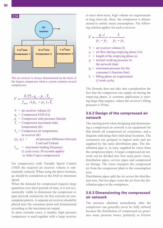
90
V = air receiver volume (l)qC = Compressor FAD (l/s)p1 = Compressor inlet pressure (bar(a)) T1 = Compressor maximum inlet temperature (K)T0 = Compressor air temperature in receiver (K)(pU -pL) = set pressure difference between Load and Unloadfmax = maximum loading frequency (1 cycle every 30 seconds applies to Atlas Copco compressors)
For compressors with Variable Speed Control (VSD) the required air receiver volume is sub-stantially reduced. When using the above formula, qc should be considered as the FAD at minimum speed.When the demand for compressed requires large quantities over short periods of time, it is not eco-nomically viable to dimension the compressor or pipe network exclusively for this extreme air con-sumption pattern. A separate air receiver should be placed near the consumer point and dimensioned according to the maximum air output.In more extreme cases, a smaller, high pressure compressor is used together with a large receiver
to meet short-term, high volume air requirements at long intervals. Here, the compressor is dimen-sioned to satisfy mean consumption. The follow-ing relation applies for such a receiver:
V = air receiver volume (l)q = air fl ow during emptying phase (l/s)t = length of the emptying phase (s)p1 = normal working pressure in the network (bar)p2 = minimum pressure for the consumer’s function (bar)L = fi lling phase air requirement (1/work cycle)
The formula does not take into consideration the fact that the compressor can supply air during the emptying phase. A common application is start-ing large ship engines, where the receiver’s fi lling pressure is 30 bar.
3.6.2 Design of the compressed air networkThe starting point when designing and dimension-ing a compressed air network is an equipment list that details all compressed air consumers, and a diagram indicating their individual locations. The consumers are grouped in logical units and are supplied by the same distribution pipe. The dis-tribution pipe is, in turn, supplied by risers from the compressor plant. A larger compressed air net-work can be divided into four main parts: risers, distribution pipes, service pipes and compressed air fi ttings. The risers transport the compressed air from the compressor plant to the consumption area.Distribution pipes split the air across the distribu-tion area. Service pipes route the air from the dis-tribution pipes to the workplaces.
3.6.3 Dimensioning the compressed air networkThe pressure obtained immediately after the compressor can generally never be fully utilized because the distribution of compressed air gener-ates some pressure losses, primarily as friction
3:34
The air receiver is always dimensioned on the basis of the largest compressor when a system contains several compressors.
CAM_edition8_2014.indd 90 13/04/15 14:53

91
losses in the pipes. In addition, throttling effects and changes in the direction of fl ow occur in valves and pipe bends. Losses, which are converted to heat, result in pressure drops that can be calculated using the following equation for a straight pipe:
∆p = pressure drop (bar)qc = air fl ow, FAD (l/s)d = internal pipe diameter (mm)l = length of the pipe (m)p = absolute initial pressure bar(a)
When calculating different parts of the com-pressed air network, the following values can be used for the allowed pressure drop:
Pressure drop across service pipes
0.03 bar
Pressure drop across distribution pipes
0.05 bar
Pressure drop across risers 0.02 bar
Total pressure drop acrossthe fi xed pipe installation
0.10 bar
3:35
CAM_edition8_2014.indd 91 13/04/15 14:53

92
The required pipe lengths for the different parts of the network (risers, distribution and service pipes) are determined. A scale drawing of the probable network plan is a suitable basis for this. The length of the pipe is corrected through the addition of equivalent pipe lengths for valves, pipe bends, unions etc. as illustrated in Figure 3:36. As an alternative to the above formula, when cal-culating the pipe diameter, a nomogram (shown in Figure 3:37) can be used to fi nd the most appropri-ate pipe diameter. The fl ow rate, pressure, allowed
pressure drop and the pipe length must be known in order to make this calculation. Standard pipe of the closest, largest diameter is then selected for the installation.The equivalent pipe lengths for all the parts of the installation are calculated using a list of fi ttings and pipe components, as well as the fl ow resis-tance expressed in equivalent pipe length. These “extra” pipe lengths are added to the initial straight pipe length. The network’s selected dimensions are then recalculated to ensure that the pressure drop
3:36
Some fi ttings and their infl uence on losses in pipes of various diameters. The losses are recalculated to a corresponding equivalent length of the pipe (m).
CAM_edition8_2014.indd 92 13/04/15 14:53

93
will not be too signifi cant. The individual sections (service pipe, distribution pipe and risers) should be calculated separately for large installations.
3.6.4 Flow measurementStrategically placed air fl owmeters facilitate internal debiting and economic allocation of com-pressed air utilization within the company. Com-pressed air is a production medium that should be a part of the production cost for individual depart-ments within the company. From this viewpoint, all parties concerned could benefi t from attempts at reducing consumption within the different
departments.Flowmeters available on the market today pro-vide everything from numerical values for man-ual reading, to measurement data fed directly to a computer or debiting module.These fl owmeters are generally mounted close to shut-off valves. Ring measurement requires par-ticular attention, as the meter needs to be able to measure both forward and backward fl ow.
3:37In
tern
al p
ipe
diam
eter
(mm
)
CAM_edition8_2014.indd 93 13/04/15 14:53

94
3.7 ELECTRICAL INSTALLATION
3.7.1 GeneralTo dimension and install a compressor requires knowledge of how component parts affect each other and which regulations and provisions apply.The following is an overview of the parameters that should be considered to obtain a compres-sor installation that functions satisfactorily with regard to the electrical system.
3.7.2 MotorsFor the most part, three-phase squirrel cage induc-tion motors are used for compressor operations. Low voltage motors are generally used up to 450 – 500 kW, whereas for higher power, high voltage motors are the best option.The motor protection class is regulated by stan-dards. The dust and water jet-resistant design (IP55) is preferred over open motors (IP23), which may require regular disassembly and cleaning. In other cases, dust deposits in the machine will eventually cause overheating, resulting in short-ened service life. Since the compressor package enclosure provides a fi rst line protection from dust and water, a protection class below IP55 may also be used.
The motor, usually fan-cooled, is selected to work at a maximum ambient temperature of 40˚C and an altitude of up to 1000 m. Some manufacturers offer standard motors with maximum ambient tempera-ture capability of 46°C. At higher temperatures or higher altitude, the output must be derated. The motor is usually fl ange-mounted and directly con-nected to the compressor. The speed is adapted to the type of compressor, but in practice, only 2-pole or 4-pole motors with respective speeds of 3,000 rpm and 1,500 rpm are used. The rated output of the motor is also determined by the compressor, and should be as close to the compressor’s requirement as possible.A motor that is overdimensioned is more expen-sive, requires an unnecessarily high starting cur-
rent, requires larger fuses, has a low power fac-tor and provides somewhat inferior effi ciency. A motor that is too small for the installation in which it is used is soon overloaded and is consequently at risk for breakdowns.The starting method should also be included as a parameter when selecting a motor. The motor is only started with a third of its normal starting torque for a star/delta–start. Therefore, a compari-son of the motor and compressor torque curves may be useful to guarantee proper compressor starts.
3.7.3 Starting methodsThe most common starting methods are direct start, star/delta–start and soft start. Direct start is simple and only requires a contactor and over-load protection. The disadvantage it presents is its the high starting current, which is 6–10 times the motor’s rated current, and its high starting torque, which may, for example, damage shafts and cou-plings.The star/delta–start is used to limit the starting cur-rent. The starter consists of three contactors, over-load protection and a timer. The motor is started with the star connection and after a set time (when the speed has reached 90% of the rated speed), the timer switches the contactors so that the motor is delta-connected, which is the operating mode. (For further details, see Section 1.6.5.7.)
The star/delta–start reduces the starting current to approximately 1/3 as compared to the direct start. However, at the same time, the starting torque also
3:38
Starting current with different starting methods.
CAM_edition8_2014.indd 94 13/04/15 14:53

95
drops to 1/3. The relatively low starting torque means that the motor’s load should be low dur-ing the starting phase, so that the motor virtually reaches its rated speed before switching to the delta connection. If the speed is too low, a current/torque peak as large as with a direct start will be generated when switching to the delta connection.Soft start (or gradual start), which can be an alter-native start method to the star/delta–start, is a starter composed of semiconductors (IGBT-type power switches) instead of mechanical contac-tors. The start is gradual and the starting current is limited to approximately three times the rated current.The starters for direct start and star/delta–start are, in most cases, integrated in the compressor. For a large compressor plant, the units may be placed separately in the switchgear, due to space require-ments, heat development and access for service. A starter for soft start is usually positioned sepa-rately, next to the compressor, due to heat radia-tion, but may be integrated inside the compressor package, provided the cooling system has been properly secured. High-voltage powered compres-sors always have their start equipment in a sepa-rate electrical cabinet.
3.7.4 Control voltageNo separate control voltage is usually connected to the compressor, as most compressors are fi tted with an integrated control transformer. The trans-former’s primary end is connected to the compres-sor’s power supply. This arrangement offers more reliable operation. In the event of disturbances in the power supply, the compressor will be stopped immediately and prevented from restarting.This function, with one internally-fed control volt-age, should be used in situations in which the start-er is located at a distance from the compressor.
3.7.5 Short-circuit protectionShort-circuit protection, which is placed on one of the cables’ starting points, can include fuses or a circuit breaker. Regardless of the solution you select, if it is correctly matched to the system, it will provide the proper level of protection.
Both methods present advantages and disadvan-tages. Fuses are well-known and work better than
a circuit-breaker for large short-circuit currents, but they do not create a fully-isolating break, and have long tripping times for small fault currents. A circuit-breaker creates a quick and fully-isolating break, even for small fault currents, but demands more work during the planning stage, as compared to fuses. Dimensioning short-circuit protection is based on the expected load, but also on the limita-tions of the starter unit.
For starter short-circuit protection, see the IEC (International Electrotechnical Commission) stan-dard 60947-4-1 Type 1 & Type 2. The selection of Type 1 or Type 2 is based on how a short-circuit will affect the starter.
Type 1: “… under short circuit conditions, the contactor or starter shall cause no danger to per-sons or installation and may not be suitable forfuther service without repair and replacementof parts."
Type 2: “… under short circuit conditions, the contactor or starter shall cause no danger to persons or installation and shall be suitable for further use. The risk of light welding of the contactors is recognized, in which case the manufacturer shall indicate the maintenancemeasures …”
3.7.6 CablesCables shall, according to the provisions of the standard, “be dimensioned so that during nor-mal operations they do not experience excessive temperatures and that they shall not be damaged thermally or mechanically by an electric short-circuit”. The dimensioning and selection of cables is based on the load, allowed voltage drop, routing method (on a rack, wall etc.) and ambient tempera-ture. Fuses can be used, for example, to protect the cables and can be used for both short-circuit pro-tection and overload protection. For motor opera-tions, short-circuit protection is used (e.g. fuses) as well as separate overload protection (usually the motor protection included in the starter).Overload protection protects the motor and motor cables by tripping and breaking the starter when the load current exceeds a preset value. The short-circuit protection protects the starter, overload protection and the cables. Cable dimensioning
CAM_edition8_2014.indd 95 13/04/15 14:53

96
accounting for load is set out in IEC 60364-5-52.An additional parameter must be kept in mind when dimensioning cables and short-circuit pro-tection: the “tripping condition”. This condition signifi es that the installation must be designed so that a short-circuit anywhere in the installation will result in quick and safe breaking. Whether the condition is met is determined by, among other things, the short-circuit protection and the cable length and cross-section.
3.7.7 Phase compensationThe electric motor does not only consume active power, which can be converted into mechanical work, but also reactive power, which is needed for the motor’s magnetization. The reactive power loads the cables and transformer. The relationship between the active and reactive power is deter-mined by the power factor, cos φ. This is usually between 0.7 and 0.9, where the lower value refers to small motors. The power factor can be raised to virtually 1 by generating the reactive power directly by the machine using a capacitor. This reduces the need for drawing reactive power from the mains. The reason behind phase compensation is that the pow-
er supplier may charge for drawing reactive power over a predetermined level, and that heavily loaded transformers and cables need to be off-loaded.
3.8 SOUND
3.8.1 GeneralAll machines generate sound and vibration. Sound is an energy form that propagates as longitudinal waves through the air, which is an elastic medium. The sound wave causes small changes in the ambi-ent air pressure, which can be registered by a pres-sure sensitive instrument (e.g. a microphone.)A sound source radiates sound power and this results in a sound pressure fl uctuation in the air. Sound power is the cause of this. Sound pressure is the effect. Consider the following analogy: an electric heater radiates heat into a room and a tem-perature change occurs. The temperature change in the room is obviously dependent on the room itself. But, for the same electrical power input, the heater radiates the same power, which is almost independent of the environment. The relation-ship between sound power and sound pressure is similar. What we hear is sound pressure, but this pressure is caused by the sound power of the sound source.Sound power is expressed in Watts. The sound power level is expressed in decibels (dB), i.e. a logarithmic scale (dB scale) with respect to a refer-ence value that is standardized:
LW = sound power level (dB)W = actual sound power (W)W0 = reference sound power (10–12 W)
3:39
Simplifi ed schematic for electric motor connection to mains power supply.
3:40
Reactive power Qc is supplied to increase the motor power factor cos(φ) to 1.
CAM_edition8_2014.indd 96 13/04/15 14:53

97
The sound pressure is expressed in Pa. The sound pressure level is equally expressed in decibels (dB), i.e. a logarithmic scale (dB scale) with respect to a reference value that is standardized:
Lp = sound pressure level (dB)p = actual sound pressure (Pa)p0 = reference sound pressure (20 x 10-6 Pa)
The sound pressure that we observe is dependent on the distance from the source and on the acous-tic environment in which the sound wave is propa-gated. For indoor noise propagation, it therefore depends on the size of the room and on the sound absorption of the surfaces. Consequently, the noise emitted by a machine cannot be fully quantifi ed by exclusively measuring sound pressure. Sound power is more or less independent of the environ-ment, whereas sound pressure is not.Information about the sound pressure level must thus always be supplemented with additional infor-mation: the distance of the measurement position from the sound source (e.g. specifi ed according to a certain standard) and the Room Constant for the room in which the measurement was made. Other-wise, the room is assumed to be limitless (i.e. an open fi eld.) In a limitless room, there are no walls to refl ect the sound waves, thereby impacting the measurement.
3.8.2 AbsorptionWhen sound waves come into contact with a surface, a portion of the waves are refl ected and another portion is absorbed into the surface mate-rial. The sound pressure at a given moment there-fore always partly consists of the sound that the sound source generates, and partly of the sound that is refl ected of surrounding surfaces (after one or more refl ections).How effectively a surface can absorb sound depends on the material of which it is composed. This is usually expressed as an absorption factor (between 0 and 1, with 0 being completely refl ect-ing and 1 being completely absorbing).
3.8.3 Room ConstantThe impact of a room on the propagation of sound waves is determined by the Room Constant. A Room Constant for a room having several surfac-es, walls and other inside surfaces can be calculat-ed by taking into account the sizes and absorption characteristics of the various surfaces. The equa-tion that applies is:
K = Room Constantα = average absorption factor of the roomA = total room surface area (m2)A1, A2 etc. are the individual room surfacesthat have absorption factors α1, α2 etc.
3.8.4 ReverberationA Room Constant can also be determined using the measured reverberation time. The reverberation time T is defi ned as the time it takes for the sound pressure to decrease by 60 dB once the sound source has been shut off. The average absorption factor for the room is then calculated as:
V = volume of the room (m3)T = reverberation time (s)
The Room Constant K is then obtained from the expression:
A = total room surface area (m2)
Absorption coeffi cients for different surface mate-rials are frequency-dependant and are therefore the derived reverberation time and the room constant.
CAM_edition8_2014.indd 97 13/04/15 14:53

98
3.8.5 Relationship between sound power level and sound pressure levelUnder some particular conditions, the relationship between sound power level and sound pressure level can be expressed in a simple manner.If sound is emitted from a point-like sound source inside a room without any refl ecting surfaces or outdoors where no walls are close to the sound source, the sound is distributed equally in all directions and the measured sound intensity will therefore be the same at any point with the same distance from the sound source. Accordingly, the intensity is constant at all points on a spherical sur-face surrounding the sound source.When the distance to the source is doubled, then the spherical surface at that distance will have quadrupled. From this, we can infer that the sound pressure level falls by 6 dB each time the distance to the sound source is doubled. However, this does not apply if the room has hard, refl ective walls. If this is the case, the sound refl ected by the walls must be taken into account.
Lp = sound pressure level (dB)Lw = sound power level (dB)Q = direction factorr = distance to the sound source
For Q, the empirical values may be used (for other positions of the sound source the value of Q must be estimated):
Q=1 If the sound source is suspended in the middle of a large room.
Q=2 If the sound source is placed close tothe center of a hard, refl ective wall.
Q=4 If the sound source is placed close tothe intersection of two walls.
Q=8 If the sound source is placed close toa corner (intersection of three walls).
If the sound source is placed in a room where the border surfaces do not absorb all the sound, the sound pressure level will increase due to the rever-
beration effect. This increase is inversely propor-tional to the Room Constant:
In the proximity of the power source, the sound pressure level drops by 6 dB each time the distance is doubled. However, at greater distances from the source, the sound pressure level is dominated by the refl ected sound, and therefore, the decrease is minimal with increasing distance.Machines which transmit sound through their bodies or frames do not behave as point sources if the listener is at a distance from the centre of the machine that is smaller than 2–3 times the machine’s greatest dimension.
3.8.6 Sound measurementsThe human ear distinguishes sound at different frequencies with different perception effi ciency. Low frequencies or very high frequencies are per-ceived less intensely than frequencies at around 1000–2000 Hz. Different standardized fi lters adjust the measured levels at low and high fre-quencies to emulate the human ear’s ability to hear sounds. When measuring occupational and indus-trial noise, the A-fi lter is commonly used and the sound level is expressed as dB(A).
3:41
Frequency dependency of the different fi lters used to weight sound levels when measuring sound. Most com-mon is the A-fi lter.
Frequency (Hz)
CAM_edition8_2014.indd 98 13/04/15 14:53

99
3.8.7 Interaction of several sound sourcesWhen more than one sound source emits sound toward a common receiver, the sound pressure increases. However, because sound levels are defi ned logarithmically, they cannot simply be added algebraically. When more than two sound sources are active, two are fi rst added together, and the next is then added to the sum of the fi rst, and so on. For memory, when two sound sources with the same levels must be added, the result is an increase of 3 dB. The formula for adding two sound levels (sound pressure levels as well as sound power lev-els) is as follows:
A similar formula applies to subtracting sound levels.
Background sound is a special case, which requires subtraction. Background sound is treated as a sep-arate sound source and the value is deducted from the measured sound level.
3.8.8 Sound reductionThere are fi ve different ways to reduce sound. Sound insulation, sound absorption, vibration insulation, vibration dampening and dampening of the sound source. Sound insulation involves an acoustic barrier being placed between the sound source and the receiver. This means that only a part of the sound can be insulated, depending on the area of the bar-rier and its insulation characteristics. A heavier and larger barrier is more effective than a lighter, smaller barrier.Sound absorption involves the sound source being surrounded by light, porous absorbents attached to a barrier. Thicker absorbents are more effec-tive than thinner absorbents and typical minimum
3:42
3:43
The nomogram defi nes how many dB shall be added to the highest sound level when adding two sound levels.
The nomogram defi nes how many dB shall be deducted from the total sound level at different background sound levels in order to estimate the net sound level.
CAM_edition8_2014.indd 99 13/04/15 14:53

100
densities are approx. 30 kg/m3 for open-cell poly-urethane foam and approx. 150 kg/m3 for mineral wool. Vibration insulation is used to prevent the transfer of vibrations from one part of a structure to anoth-er. A common problem is the transfer of vibra-tions from a built-in machine to the surrounding sound insulation barrier or down to the fl oor. Steel springs, air springs, cork, plastic, and rubber are examples of materials used for vibration insula-tion. The choice of materials and their dimension-ing is determined by the frequency of the vibration and by the demands of stability for the machine setup.Vibration dampening involves a structure being fi t-ted with an external dampening surface composed of elastic material with a high hysteresis. When the dampening surface applied is suffi ciently thick, the barrier wall will effectively be prevented from vibrating and, consequently, from emitting sound. Dampening of a sound source will often infl uence its operational behavior. It may give limited results, yet provide a viable solution in terms of cost.
3.8.9 Noise within compressor installationsCompressor noise level is measured in a standard-ized fashion on a machine (in an acoustic free fi eld e.g. outdoors, without walls or by means of a sound intensity scanning technique). When the compressor is installed in a room, the noise level is infl uenced by the properties of the room. The size of the room, the materials used for the walls and ceiling, and the presence of other equipment (and its potential noise levels) in the room all have signifi cant impacts.Furthermore, the positioning of the compressor in the room also affects the noise level due to the set-up and connection of pipes and other components. Sound radiating from compressed air pipes is fre-quently more problematic than the noise produced by the compressor itself and its power source. This can be due to vibration transferred mechanically to the pipes, often in combination with vibration transferred through the compressed air. It is there-fore important to fi t vibration insulators and even enclose sections of the pipe system using a combi-nation of sound-absorbing material covered with a sealed insulation barrier.
CAM_edition8_2014.indd 100 13/04/15 14:53

4ECONOMY
CAM_edition8_2014.indd 101 13/04/15 14:53

102
4.1 COST
4.1.1 Compressed air production cost
4.1.1.1 GeneralElectrical energy is the most prevalent energy source for industrial compressed air production. In many compressed air installations there are often signifi cant and unutilized energy-saving possibili-ties including energy recovery, pressure reduction, leakage reduction and optimization of operations through correct choice of a control and regulation system as well as the choice of compressor size.
When planning a new investment, it is best to look as far into the future as possible and attempt to assess the impacts of new situations and demands that might affect the compressed air installation. Typical examples include environmental demands, energy-saving demands, increased quality require-ments from production and future production expansion investments.Optimized compressor operations are becoming more important, especially for larger, compressed air-dependent industries. Production will change over time in a developing industry and, conse-quently, so will compressor operation conditions. It is therefore important that the compressed air supply be based both on current requirements as
well as on development plans for the future. Expe-rience shows that an extensive and unbiased anal-ysis of the operating situation will almost always result in improved overall economy.
Energy costs are clearly the dominating factor for the installation’s overall cost. It is therefore impor-tant to focus on fi nding solutions that comply with demands for performance and quality as well as the demand for effi cient energy utilization. The added cost associated with acquiring compres-sors and other equipment that complies with both of these demands will be perceived over time as a good investment.As energy consumption often represents approx. 80% of the overall cost, care should be taken in selecting the regulation system. The signifi cant difference in the available regulation systems exceeds the signifi cant differences in types of compressor. An ideal situation is when compressor full capacity is precisely matched to the applica-tion’s air consumption. This frequently occurs in process applications. Most types of compressors are supplied with their own on-board control and regulation system, but the addition of equipment for shared control with other compressors in the installation can further improve operating econo-my.Speed regulation has proven to be a popular regu-lation method because of its substantial energy-saving potential. Think carefully and allow your application requirements to govern your selection of regulation equipment in order to obtain good results. If only a small amount of compressed air is required during the night and weekends, it may be profi t-able to install a small compressor adapted to this off-peak requirement. If, for some reason, a par-ticular application needs a different working pres-sure, this requirement should be analyzed to fi nd out whether all compressed air production should be centralized in a compressor central plant, or whether the network should be split up according to the different pressure levels. Sectioning of the compressed air network can also be considered to shut down certain sections during the night and on the weekends, in order to reduce air consumption or to allocate costs internally based on air fl ow measurements.
4:1
When analyzing the cost contributors to the production of compressed air one will fi nd a breakdown similar to the one in the diagram. However, the relative weight of the different types of costs may change with the number of operating hours/year, with the auxiliary equipment included in the calculation, with the type of machine and the selected cooling system, etc.
CAM_edition8_2014.indd 102 13/04/15 14:53

103
4.1.1.2 Cost allocationInvestment costs are a fi xed cost that include the purchase price, building infrastructure costs, installation and insurance. The share of the investment cost as a part of the overall cost is determined partly by the selection of the compressed air quality level and partly by the depreciation period and the applicable interest rate.The share of energy costs is determined by annual operating time, the degree of load/unload utiliza-tion and the unit energy cost.Additional investments, for example, equipment for energy recovery, offer a direct payoff in the form of reduced operating and maintenance costs.
For comparisons between different investment alternatives, the use of comparable values is particularly important. Therefore, the values must be stated in accordance with internationally recognized standards and regulations, for example,as per ISO 1217 Ed.4 -2009.
4.2.2 Working pressureThe working pressure directly affects the power requirement. Higher pressure signifi es higher energy consumption: on average 8% more power for 1 bar higher pressure. Increasing the working pressure to compensate for a pressure drop always results in impaired operating economy.Despite this adverse economic effect, increasing compressor pressure is a commonly-used method for overcoming pressure drops caused by an under-dimensioned pipe system or clogged fi lters. In an installation fi tted with several fi lters, especially if they have been operational for a long period of time without being replaced, the pressure drop can be signifi cantly higher and therefore very costly if unattended for long periods of time.In many installations, it is not possible to imple-
4:2
4:3
This chart illustrates how costs may be divided between 3 compressors and their auxiliary equipment. The large differences may be due to how the machines are valued, to the individual capital value of the equipment, to the selected level of safety that can affect the maintenance costs, etc.
A simple but useful model that can be used to give a true picture of a compressor’s electrical energy requirement.
€
4.2 OPPORTUNITIES FOR SAVING
4.2.1 Power requirementWhen making calculations, it is important to apply the overall power requirement concept. All energy consumers that belong to a compressor installation should be accounted for: for example, inlet fi lters, fans and pumps, dryers and separators.
CAM_edition8_2014.indd 103 13/04/15 14:53

104
ment large pressure reductions, but the use of mod-ern regulation equipment allows the pressure to be realistically lowered by 0.5 bar. This represents a power savings of a few percent. This may seem to be insignifi cant, but considering that the total effi -ciency of the installation is increased by an equiva-lent degree, the value of this pressure reduction in terms of actual savings is more readily obvious.
4.2.3 Air consumptionBy analyzing routines and the use of compressed air, solutions to provide a more balanced load on
the compressed air system can be found. The need for increased air fl ow production can thereby be avoided to reduce operating costs.Unprofi table consumption, which usually is a consequence of leakage, worn equipment, pro-cesses that have not been properly confi gured or the incorrect use of compressed air, is best recti-fi ed by increasing general awareness. Dividing the compressed air system into sections that can be separated using shut-off valves can serve to reduce consumption during the night and over weekends. In most installations, there is some degree of leak-
4:4
4:5
Excess power requirement as a result of over-pressurizing to compensate for pressure drops. For a 300 l/s compressor, raising the working pressure by 1 bar means 6 kW higher power consumption. At 4000 operating hours/year this repre-sents 24,000 kWh/year or € 2,400/year.
The pressure drop across different components in the network affects the requisite working pressure.
CAM_edition8_2014.indd 104 13/04/15 14:53

105
age, which represents a pure loss and must there-fore be minimized. Frequently leakage can amount to 10-15% of the produced compressed air fl ow. Leakage is also proportional to the working pres-sure, which is why one method of reducing leakage is to repair leaking equipment, and thereby lower-ing the working pressure, for example, at night.Lowering the pressure by only 0.3 bar reduces leakage by 4%. If the leakage in an installation of 100 m3/min is 12% and the pressure is reduced by 0.3 bar, this represents a saving of approx. 3 kW.
4.2.4 Regulation methodUsing a modern master control system, the com-pressor central plant can be run optimally for dif-ferent operating situations while enhancing safety and availability. Selecting the right regulation method encourages energy savings through lower system pressure and a better degree of utilization, which is optimized for each machine in the installation. At the same time availability increases, thereby reducing the risk of unplanned downtime. Also, central control allows programming for automatic pressure reduc-tion in the entire system during operation at night and on weekends.
4:6
4:7
The diagram shows how air consumption can be varying during a week and 24 hours per day. Consumption is low during the night shift, is high during the day shift, and drops during breaks, but is constant during the weekends (leakage?).
The table illustrates the relation between leakage and power consumption for some small leakage holes at a system pressure of 7 bar(e).
CAM_edition8_2014.indd 105 13/04/15 14:53

106
As compressed air consumption is seldom con-stant, the compressor installation should have a fl exible design, using a combination of compres-sors with different capacities and speed-controlled motors. Compressors may run with speed-control and screw compressors are particularly suited for this, as their fl ow rate and their power consump-tion are virtually proportional to their speed.
4.2.5 Air qualityHigh quality compressed air reduces the need for maintenance, increases operating reliability of the pneumatic system, control system and instru-mentation while limiting wear of the air-powered machines.If the compressed air system is conceived for dry, oil-free compressed air from the start, the instal-
4:8
4:9
Cost comparison of different drying methods.
Oil-free compressors give constant compressed air quality at a fi xed energy cost.
CAM_edition8_2014.indd 106 13/04/15 14:53

107
lation will be less expensive and simpler, as the pipe system does not need to be fi tted with a water separator. When the air is dry, it is not necessary to discharge air into the atmosphere to remove condensation. Condensation drainage on the pipe system is also not required, which means lower costs for installation and maintenance. The most economic solution can be obtained by installing a central compressed air dryer. Decentralizing air treatment modules with several smaller units placed in the system is more expensive and makes the system harder to maintain.
Experience has shown that the reduced installation and maintenance costs for a system with dry com-pressed air will cover the investment cost of the drying equipment. Profi tability is very high, even when drying equipment must be added to existing installations.Oil-free compressors do not require an oil separa-tor or cleaning equipment for condensation. Filters are not needed either and the cost for fi lter replace-ment is therefore eliminated. Consequently, there is no need to compensate for the pressure drop in the fi lter and the compressor’s working pressure can be lowered. This contributes to improving the installation’s economy even further.
4.2.6 Energy recoveryWhen using electricity, gas or oil for any form of heating within the production facilities or in the process, the possibility of fully or partly replac-ing this energy with recovered waste energy from the compressor installation should be investigated.The decisive factors are the energy cost in €/kWh, the degree of utilization and the amount of additional investment necessary. A well-planned investment in waste energy recovery often gives a payback time of only 1–3 years. Over 90% of the power supplied to the compressor can be recovered in the form of highly valuable heat. The tempera-ture level of the recovered energy determines the possible application areas and, therefore, its value.The highest degree of effi ciency is generally obtained from water-cooled installations, when the compressor installation’s hot cooling water outlet can be connected directly to a continuous heating demand, for example the existing heating boiler’s return circuit. Recovered waste energy can then be effectively utilized year round. Different compres-sor designs give different prerequisites. In some situations requiring a large and peaking heat fl ow, long heat transport distances to the point of utiliza-tion, or a requirement that varies during the year, it may be interesting to look at the possibilities of selling the recovered energy in the form of heat or cooling or electricity, etc.
4:10
At the same time as the compressor produces compressed air, it also converts the supplied energy into heat, which is transferred to the coolant, air or water. Only a small part is contained in the compressed air and is emitted as heat radia-tion from the machine and piping.
CAM_edition8_2014.indd 107 13/04/15 14:53

108
4.2.7 MaintenanceAs with all equipment, a compressor installation requires some form of maintenance. However, maintenance costs are low in relation to other costs and can be reduced further through careful planning measures. The choice of the maintenance level is determined by the required reliability and performance of the compressed air installation.Maintenance makes up the smallest part of the installation’s total cost of ownership. It depends on how the installation has been planned in general and the particular choice of compressor and aux-iliary equipment.Costs can be reduced by combining condition mon-itoring with other functions when using equipment for fully automatic operations, and monitoring of the compressor central plant. The total budget for maintenance is affected by:
- Type of compressors- Auxiliary equipment (dryers, fi lters, control and regulation equipment)- Operating cycle load/unload- Installation conditions- Media quality- Maintenance planning- Choice of safety level- Energy recovery/cooling system- Degree of utilization
The annual maintenance cost is usually between 5–10% of the machine’s investment value.
4.2.7.1 Maintenance planningWell-planned compressor maintenance allows costs to be anticipated and the service life of the machine and auxiliary equipment to be extended as a result. Costs for repairing small faults is also decreased and downtime is shortened. By utilizing advanced electronics to a greater degree, machines are equipped with instruments for diagnostic examination. This means that component parts can be utilized optimally and replacement takes place only when truly needed. The need for reconditioning components can be discovered at an early stage before damage is sig-nifi cant, thereby avoiding subsequent damage and unnecessary downtime.By utilizing the compressor supplier’s after-market services, its staff and original spare parts, the machine can be expected to maintain a high technical operational standard, while offering the possibility of introducing modifi cations based on recent experiences during the machine’s service life. The assessment of the maintenance require-ment is made by specially-trained technicians, who also conduct training for in-house fi rst-line maintenance staff. In-house skilled staff should preferable be used to perform daily inspections, as local ears and eyes can hear and see things that remote monitoring equipment cannot.
4:11
The highest possible degree of utilization reduces the cost of service and maintenance, expressed in €/operating hour. It is realistic to plan for 100% utilization and at least 98% availability.
CAM_edition8_2014.indd 108 13/04/15 14:53

109
4.2.7.2 Auxiliary equipmentIt is easy to expand an installation by adding numerous pieces of auxiliary equipment, for example, to increase the air quality or to moni-tor the system. However, even auxiliary equip-ment needs service and incurs maintenance costs (e.g. fi lter replacement, drying agent replacement, adaptation to other equipment and staff training.)In addition, secondary maintenance costs exist, for example, for the distribution network and produc-tion machines, which are affected by the quality of the compressed air, and include deposit costs for oil and fi lter cartridges. All of these costs must be evaluated in the cost of ownership calculation that forms the basis for any new compressor invest-ment.
4.3 LIFE CYCLE COST
4.3.1 GeneralA common way to describe and analyze the invest-ment in a product, a material or a particular ser-vice in a systematic, yet simplifi ed fashion, is by using a life cycle cost (LCC) analysis. This analy-sis examines all of the stages in the life cycle of the operating product or the service. This includes everything from the selection of raw material to fi nal waste removal/recycling.The analysis is often used as a comparison tool between different investment options, for example,
4:12
CAM_edition8_2014.indd 109 13/04/15 14:53
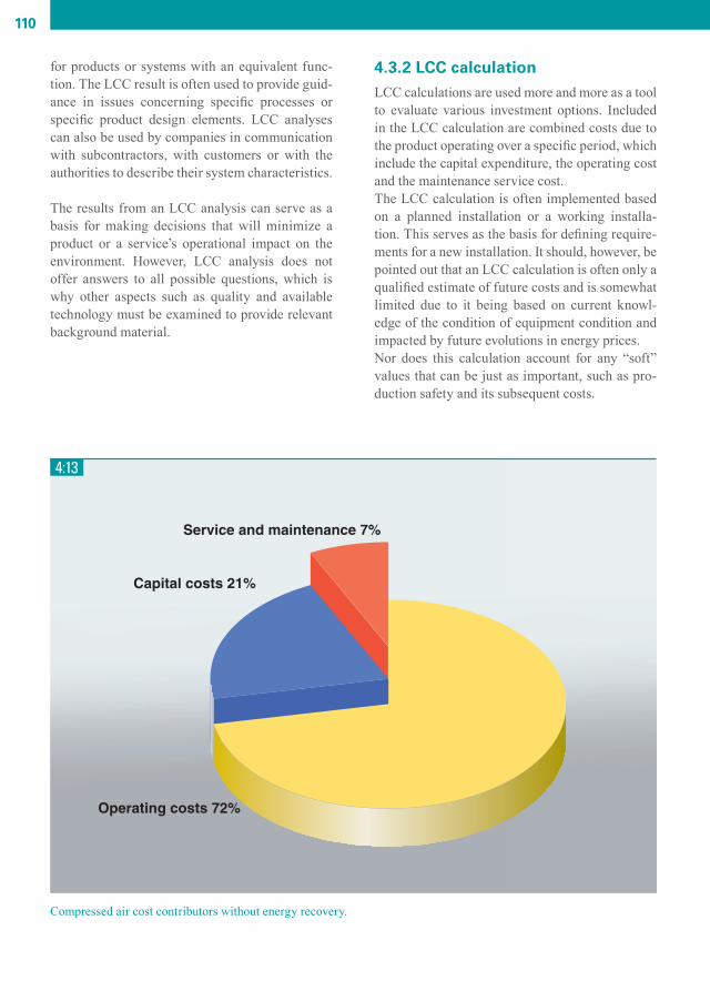
110
for products or systems with an equivalent func-tion. The LCC result is often used to provide guid-ance in issues concerning specifi c processes or specifi c product design elements. LCC analyses can also be used by companies in communication with subcontractors, with customers or with the authorities to describe their system characteristics.
The results from an LCC analysis can serve as a basis for making decisions that will minimize a product or a service’s operational impact on the environment. However, LCC analysis does not offer answers to all possible questions, which is why other aspects such as quality and available technology must be examined to provide relevant background material.
4.3.2 LCC calculationLCC calculations are used more and more as a tool to evaluate various investment options. Included in the LCC calculation are combined costs due to the product operating over a specifi c period, which include the capital expenditure, the operating cost and the maintenance service cost.The LCC calculation is often implemented based on a planned installation or a working installa-tion. This serves as the basis for defi ning require-ments for a new installation. It should, however, be pointed out that an LCC calculation is often only a qualifi ed estimate of future costs and is somewhat limited due to it being based on current knowl-edge of the condition of equipment condition and impacted by future evolutions in energy prices.Nor does this calculation account for any “soft” values that can be just as important, such as pro-duction safety and its subsequent costs.
4:13
Compressed air cost contributors without energy recovery.
CAM_edition8_2014.indd 110 13/04/15 14:53

111
Making an LCC calculation requires knowledge and preferably experience with other compressed air installations. Ideally, it should be made jointly by the purchaser and the salesman. Critical issues include how different investment options affect factors like production quality, production safety, subsequent investment requirements, produc-tion machine and the distribution network main-tenance, environmental impact, the quality of the fi nal product, and risks for downtime and for rejections. An expression that must not be forgot-ten in this context is LCP, Life Cycle Profi t. This represents the earnings that can be gained through energy recovery and reduced rejections, to name but a few possibilities.When assessing service and maintenance costs, the equipment’s expected condition at the end of the calculation period must also be taken into account (i.e. whether it should be seen as fully used or be restored to its original condition).Furthermore, the calculation model must be adapted to the type of compressor involved. The
4:14
Compressed air cost contributors with energy recovery.
example in chapter 5 can serve as a model for the economic assessment of a compressor installation, with or without energy recovery.
CAM_edition8_2014.indd 111 13/04/15 14:53

CAM_edition8_2014.indd 112 13/04/15 14:53
5CALCULATION EXAMPLE
CAM_edition8_2014.indd 113 13/04/15 14:53

114
5.1 EXAMPLE OF DIMENSIONING COMPRESSED AIR INSTALLATIONS
The following paragraphs contain calculations for dimensioning a typical compressed air installation. Their purpose is to show how some of the formulas and reference data from previous chapters are used. The example is based on a given compressed air requirement and the resulting dimensioned data are based on components that have been selected for this particular compressed air installation. Following the paragraph dealing with a typical case are a few additional paragraphs that illustrate how spe-cial cases can be handled: high altitude, intermittent output, energy recovery and calculating pressure drop in the piping.
5.2 INPUT DATA
The quantitative compressed air requirements and the local ambient conditions must be established before starting any dimensioning. In addition to this quantitative requirement, a qualitative selection involving whether the compressor should be oil-lubricated or oil-free and whether the equipment should be water-cooled or air-cooled must be made.
5.2.1 Compressed Air RequirementAssume that the installation contains three compressed air consumers with the following data:
Consumer Air Flow Pressure Dew Point
1 12 Nm3/min 6 bar(e) +6°C
2 67 l/s (FAD) 7 bar(a) +6°C
3 95 l/s (FAD) 4 bar(e) +6°C
5.2.2 Ambient conditions for dimensioningNormal ambient temperature: 20°CMaximum ambient temperature: 30°CAmbient pressure: 1 bar(a)Humidity: 60%
5.2.3 Additional specificationsAir-cooled equipment only.Compressed air quality from oil-lubricated compressors.
CAM_edition8_2014.indd 114 13/04/15 14:53

115
5.3 COMPONENT SELECTION
Recalculate all input data from the requirement table in 5.2.1, to ensure that it is normalized with regard to measurement units before dimensioning the different components.
Flow conversion: In general, the unit l/s is used to define compressor capacity, which is why consumer 1, given in Nm3/min, must be recalculated in l/s.
12 Nm3/min = 12 x 1000/60 = 200 Nl/s.Inserting the current input data in the formula gives:
qFAD = Free Air Delivery (l/s)qN = Normal volume rate of flow (Nl/s)TFAD = maximum inlet temperature (30°C)TN = Normal reference temperature (0°C)pFAD = standard inlet pressure (1.00 bar(a))pN = Normal reference pressure (1.013 bar(a))
Pressure conversion: The unit generally used to define pressure for compressed air components is effective pressure (also called gauge pressure), stated in bar(e).
Consumer 2 is stated in absolute pressure, 7 bar(a). The ambient pressure is subtracted from 7 bar to yield the effective pressure. As the ambient pressure in this case is 1 bar(a) the pressure for consumer 2 can be written as (7-1) bar(e) = 6 bar(e).
With the above recalculations, the table with uniform requirement data becomes:
Consumer Air Flow Pressure Dew Point
1 225 l/s (FAD) 6 bar(e) +5°C
2 67 l/s (FAD) 6 bar(e) +5°C
3 95 l/s (FAD) 4 bar(e) +5°C
5.3.1 Dimensioning the compressorThe total air consumption is the sum of the three consumers 225 + 67 + 95 = 387 l/s. Taking into account pos-sible changes in the planned air consumption data, and later incremental expansion of compressed air needs, a safety margin of approx. 10-20% should be added. This gives a dimensioned flow rate of 387 x 1.15 ≈ 450 l/s (including the 15% safety margin).
CAM_edition8_2014.indd 115 13/04/15 14:53

116
The maximum required pressure for all consumers is 6 bar(e). A reducing valve should be fitted to the con-sumer number 3 with the requirement of 4 bar(e). Assuming that the combined pressure drop in the dryer, filter and piping does not exceed 1.5 bar, a compres-sor with a maximum working pressure capability of no less than 6 + 1.5 = 7.5 bar(e) is suitable for this case.
5.3.2 Final compressor selectionA compressor with the following specifications is selected:
Oil-injected screw compressor typeMaximum compressor outlet pressure = 7.5 bar(e)FAD at 7 bar(e) = 450 l/s This requirement is met by a compressor with installed motor shaft power = 162 kW.The compressed air temperature out of the compressor aftercooler = ambient temperature +10°C.Furthermore, the selected compressor has loading/unloading regulation with a maximum cycle frequency of 30 seconds. Using loading/unloading regulation, the selected compressor has a pressure fluctuation between 7.0 and 7.5 bar(e).
5.3.3 Dimensioning the air receiver volumeqC = compressor capacity = 450 l/sp1 = compressor inlet pressure = 1 bar(a)T1 = maximum inlet temperature = 30°C = 273 + 30 = 303 Kfmax = maximum cycle frequency = 1 cycle/30 seconds(pU - pL) = pressure difference between Loaded and Unloaded compressor = 0.5 barT0 = compressed air temperature out of the selected compressor is 10°C higher than the ambienttemperature; therefore the maximum temperature in the air receiver will be = 273 + 40 = 313 K
Compressor with loading/unloading regulation gives the following formula for the air receiver volume:
This is the minimum recommended air receiver volume. The next larger standard size is usually selected.
5.3.4 Dimensioning the dryerThe required dew point in this example is +5°C, therefore a refrigerant dryer is the most suitable choice of dryer. When selecting the dryer size a number of factors must be taken into consideration and the refrigerant dryer capacity should be corrected using appropriate correction factors. These correction factors are unique to each refrigerant dryer model. In the case below, the correction factors applicable for Atlas Copco refriger-ant dryers are used, and they are stated on the Atlas Copco product data sheet. The correction factors are:
1. Refrigerant dryer inlet temperature and pressure dew point. Because the compressed air temperature out of the compressor is 10°C higher than the ambient tempera-
ture, the refrigerant dryer inlet temperature will be maximum 30 + 10 = 40°C. In addition, the desired pressure dew point is +5°C.
The appropriate correction factor 0.95 is obtained from the Atlas Copco data sheet.
CAM_edition8_2014.indd 116 13/04/15 14:53

117
2. Working pressureThe actual working pressure is approx. 7 bar, which represents a correction factor of 1.0.
3. Ambient temperature For a maximum ambient temperature of 30°C a correction value of 0.95 is obtained. Consequently, the refrigerant dryer should be able to handle the compressor’s full capacity multiplied by
the correction factors above. 450 x 0.95 x 1.0 x 0.95 = 406 l/s.
5.3.5 Summary for continued calculationAn air-cooled refrigerant dryer with the followed data is selected:Capacity at 7 bar(e) = 450 l/sTotal power consumption = 5.1 kWEmitted heat fl ow to surroundings = 14.1 kWPressure drop across the dryer = 0.09 bar
5.3.6 Checking calculationsWhen all components for the compressor installation have been selected, it must be ensured that the total pressure drop is not too great. This is done by adding up all of the pressure drops for the components and pipes. It may be appropriate to draw a schematic diagram of the compressed air installation as shown in Figure 5:1.
5:1
The pressure drop for the components is obtained from the component suppliers, while the pressure drop in the pipe system should not exceed 0.1 bar.The total pressure drop can now be calculated:
Component Pressure drop (bar)
Oil fi lter (pressure drop when fi lter is new) 0.08
Refrigerant dryer 0.09
Dust fi lter (pressure drop when fi lter is new) 0.08
Pipe system in compressor central plant 0.05
Pipes from compressor central plant to consumption points 0.1
Total pressure drop: 0.4
CAM_edition8_2014.indd 117 13/04/15 14:53

118
The maximum unloaded pressure of 7.5 bar(e) and load pressure of 7.0 bar(e) for the selected compressor gives a lowest pressure at the consumers of 7.0 - 0.4 = 6.6 bar(e). Add to this the additional pressure drop increase across the filter that occurs over time. This pressure drop increase is unique for each filter type and can be obtained from the Atlas Copco product data sheet.
5.4 ADDITIONAL DIMENSIONING WORK
5.4.1 Condensation quantity calculationBecause an oil-lubricated compressor has been chosen, the water condensation separated in the compressor and refrigerant dryer will contain small amounts of oil. The oil must be separated before the water is released into the sewer, which can be done using oil separator. Information on how much water is condensed is needed in order to properly dimension the oil separator.
The total amount of water in the air flow taken in by the compressor is obtained from the relation:f1 = relative humidity x the amount of water (g/liter) that the air can carry at the maximum ambient tempera-ture 30°C x air flow.
f2 = amount of air remaining in the compressed air after drying (saturated condition at +6°C).
f2 =1x0.007246x445
80.4g /s
The total condensation flow from the installation f3 then becomes:
f3 = f1 - f2 = 8.0 - 0.4 = 7.6 g/s ≈ 27.4 kg/hour
This figure assumes continuous load for one hour.With the help of the calculated condensation flow, the right oil separator can now be chosen. 5.4.2 Ventilation requirement in the compressor roomThe principle that the heat released into the room air will be removed with the ventilation air is used to deter-mine the ventilation requirement in the compressor room.For this calculation the following relationship is used:
P = m x cP x ∆TP = the total heat flow (kW)m = mass flow (kg/s)cp = specific heat (J/kg x K)∆T = temperature difference (K)
CAM_edition8_2014.indd 118 13/04/15 14:53

119
The formula for the ventilation mass flow can be written as:
where:
∆T = the maximum allowed ventilation air temperature increase (say, 10 K)cp = 1.006 kJ/kg x K (at 1 bar and 20°C)P = (roughly 94% of the supplied shaft power to the compressor + the difference between the supplied total power to the compressor package and the supplied shaft power to the compressor + the stated heat flow from the refrigerant dryer) = (0.94 x 162) + (175 - 162) + 14.1 ≈ 180 kW
Thus the ventilation air mass flow is:
At an air density of 1.2 kg/m3 this mass flow represents 17.9/1.2 ≈ 15m3/s.
5.5 SPECIAL CASE: HIGH ALTITUDE
Question: Imagine that the same compressed air requirement as described in the previous example is specified, but at an altitude of 2,500 meters above sea level and with a maximum ambient temperature of 35°C. What compressor capacity (expressed as free air delivery) is required in this case?
Answer: Air becomes thinner at higher altitudes. This is a fact that must be taken into consideration when dimensioning compressed air equipment to fulfill a compressed air requirement specified for Normal condi-tions, in Nm3/min. For cases in which the consumer flow requirement is stated in free air delivery (FAD), no recalculation is necessary.
As consumer 1 in the example above is specified in Nm3/min at 1.013 bar(a) and 0°C, the requisite FAD flow for this consumer must be recalculated for the condition 35°C at 2,500 m altitude. Using a look-up table, the ambient pressure at 2,500 meters above sea level is 0.74 bar. The flow for consumer 1, recalculated to Nl/s (12 Nm3/min = 200 Nl/s), is then entered in the formula below:
The total compressed air capacity demanded is then 309 + 67 + 95 = 471 l/s (FAD).
CAM_edition8_2014.indd 119 13/04/15 14:53

120
5.6 SPECIAL CASE: INTERMITTENT OUTPUT
Question: Imagine that in this sample calculation, there is an extra requirement from consumer 1 of a further 200 l/s for 40 seconds of every hour. During this intermittent phase, the pressure in the system is allowed to drop to 5.5 bar(e). How large should the volume of the receiver be to meet this extra requirement?
Answer: During a short period, more compressed air can be delivered than what the compressors jointly can manage by using the stored compressed air in an air receiver. However, in order to fill this air receiver between the intermittent periods in which extra air is needed, the compressor must feature a specific over-capacity. The following relation applies:
q = air flow during the emptying phase = 200 l/st = length of the emptying phase = 40 secondsp1 - p2 = permitted pressure drop during the emptying phase = normal system pressure - minimum accepted pressure at emptying phase = 6.42 - 5.5 = 0.92 bar
Inserted in the above formula for the required air receiver volume:
In addition, the compressor must have a specific over-capacity, so that it can fill the air receiver after the emp-tying phase. If the selected compressor has an over-capacity of 5 l/s = 18,000 liters/hour, the above calculated receiver volume would be filled within half an hour. As the air receiver will be emptied only once every hour, this compressor over-capacity is sufficient.
CAM_edition8_2014.indd 120 13/04/15 14:53
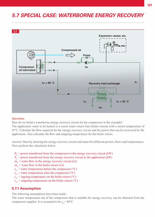
121
5.7 SPECIAL CASE: WATERBORNE ENERGY RECOVERY
5:1
Question: How do we build a waterborne energy recovery circuit for the compressor in the example? The application water to be heated is a warm water return line (boiler return) with a return temperature of 55°C. Calculate the fl ow required for the energy recovery circuit and the power that can be recovered by the application. Also calculate the fl ow and outgoing temperature for the boiler return.
Answer: Start by drawing the energy recovery circuit and name the different powers, fl ows and temperatures. Now perform the calculation below.
PE = power transferred from the compressor to the energy recovery circuit (kW)PA = power transferred from the energy recovery circuit to the application (kW)mE = water fl ow in the energy recovery circuit (l/s)mA = water fl ow in the boiler return (l/s)tE1 = water temperature before the compressor (°C)tE2 = water temperature after the compressor (°C)tA1 = ingoing temperature on the boiler return (°C)tA2 = outgoing temperature on the boiler return (°C)
5.7.1 AssumptionThe following assumptions have been made:The water temperature out of the compressor that is suitable for energy recovery can be obtained from the compressor supplier. It is assumed to be tE2= 80°C.
CAM_edition8_2014.indd 121 13/04/15 14:53

122
Assumption for the water circuit through the energy recovery heat exchanger:
tE1 = tA1 + 5°C = 55°C +5°C = 60°CtA2 = tE2 - 5°C = 80°C – 5°C = 75°C
In addition, it is assumed that the pipe system and heat exchanger have no heat exchange with the surround-ings.
5.7.2 Calculation of the water flow in the energy recovery circuitP = m x cp x ∆T
∆T = temperature increase across the compressor = tE2 - tE1 = 80°C - 60°C = 20°Ccp = specific heat capacity for water = 4.185 kJ/kg x Km = mass flow in the energy recovery circuit = mEP = 70% of the supplied shaft power = PE = 0.70 x 162 = 113 kW
This is the maximum possible power to recover from the selected compressor. The formula can be written as:
5.7.3 Energy balance across the recovery heat exchangerFor the recovery heat exchanger the following applies:
PE = mE x cp x (tE2-tE1)PA = mA x cp x (tA2-tA1)
However, as it has been presumed that no heat exchange takes place with the surroundings, the power trans-ferred to the energy recovery circuit from the compressor will be equal to the power transferred in the recov-ery heat exchanger, i.e. PA = PE = 113 kW.
The formula can be written as:
5.7.4 SummaryThe calculation illustrates that the power which can be recovered is 113 kW. This requires a water flow in the energy recovery circuit of 1.35 l/s. An appropriate flow for the boiler return is also 1.35 l/s with an increase of the boiler feed temperature by 20°C.
CAM_edition8_2014.indd 122 13/04/15 14:53

123
5.8 SPECIAL CASE: PRESSURE DROP IN THE PIPING
Question:A 23-meter pipe with an inner diameter of 80 mm shall lead a compressed air flow of qC = 140 l/s. The pipe is routed with 8 elbows that all have a bending radius equal to that of the pipe inner diameter. What will be the pressure drop across the pipe be if the initial pressure is 8 bar (a)?
Answer: First, determine the equivalent pipe length for the 8 elbows. The equivalent pipe length of 1.3 meter per elbow can be determined from Figure 3:36. The total pipe length is thus 8 x 1.3 + 23 = 33.4 meters. The following formula is used to calculate the pressure drop:
Accordingly, the total pressure drop across the pipe will be 0.0054 bar, which is very low.
CAM_edition8_2014.indd 123 13/04/15 14:53

CAM_edition8_2014.indd 124 13/04/15 14:53

6APPENDICES
CAM_edition8_2014.indd 125 13/04/15 14:53

126
6.1 THE SI SYSTEM
Any physical quantity is the product of a numeri-cal value and a unit. Since 1964, the International System of Units (SI system) has gradually been adopted worldwide, with the exception of Libe-ria, Myanmar and the United States. Basic infor-mation can be found in standard ISO 31, which is under revision and will be superseded by ISO/IEC 80000: Quantities and Units. Units are divided into four different classes:
Base unitsSupplementary unitsDerived unitsAdditional units
Base units, supplementary units and derived units are called SI units. The additional units are not SI units, although they are accepted for use with
SI units. Base units are any of the established, independent units in which all other units can be expressed.There are 7 base units in the SI system:
Length meter mMass kilogram kgTime second sElectrical current ampere ATemperature kelvin KLuminous intensity candela cdAmount of substance mole mol
Derived units are formed as a power or product of powers of one or more base units and/or supple-mentary units according to the physical laws for the relationship between these different units.
Additional units:A limited number of units outside the SI system cannot be eliminated for different reasons, and continue to be used along with the SI as additional units.
The 15 most important derived units below have been given generic names:
Quantity Unit Symbol Expressed in other SI units
frequency hertz Hz s-1
force newton N kg x m x s-2
pressure / mechanical stress pascal Pa N / m²energy / work joule J N x mpower watt W J / selectric quantity / charge coulomb C A x selectric voltage volt V W / Acapacitance farad F C / Vresistance ohm Ω V / Aconductivity siemens S A / Vmagnetic flux weber Wb V x smagnetic flux density tesla T Wb / m²inductance henry H Wb / Aluminous flux lumen lm Cd x srlight lux lx Lm / m²angle radian rad m / msolid angle steradian sr m² / m²
CAM_edition8_2014.indd 126 13/04/15 14:53

127
The following are common additional units for technical use:
Quantity Unit Symbol Remark
volume liter l 1 l = 1 dm³time minute min 1 min = 60 stime hour h 1 h = 60 minmass metric ton t 1 t = 1.000 kgpressure bar bar 1 bar = 105 Paplane angle degree .° 1° = π/180 radplane angle minute .’ 1’ = 1°/60
plane angle second .” 1” = 1’/60
Prefixes may be added to a unit to produce a mul-tiple of the original unit. All of these multiples are integer powers of ten, for example:- kilo-denotes a multiple of thousand (10³)- milli-denotes a multiple of one thousandth (10-3)
Fourteen such prefixes are listed in international recommendations (standards) as set out in the table below.
Power PrefixDesignation
PrefixSymbol Example Symbol
1012 tera T 1 terajoule 1 TJ109 giga G 1 gigahertz 1 GHz106 mega M 1 megawatt 1 MW103 kilo k 1 kilometer 1 km102 hecto h 1 hectoliter 1 hl101 deca da 1 decalumen 1 dalm10–1 deci d 1 decibel 1 dB10–2 centi c 1 centimeter 1 cm10–3 milli m 1 milligram 1 mg10–6 micro µ 1 micrometer 1 µm10–9 nano N 1 nanohenry 1 nH10–12 pico p 1 picofarad 1 pF10-15 femto f 1 femtometer 1 fm10-18 atto a 1 attosecond 1 as
For reference: www.bipm.org/en/si/
CAM_edition8_2014.indd 127 13/04/15 14:53

128
6.2 DRAWING SYMBOLS
Air fi lter
Silencer
Diffuser
Compensator
Throttle valve
Screw compressor
Non-return valve
Stop valve
Safety valve
Manual valve
Valve closing on failure of actuating energy
Valve opening on failure of actuating energy
Oil separator
Ejector
Water-cooled cooler
Water separator
Condensation receiver
Direction of fl ow
Air-cooled cooler
Fan
Expansion vessel
Minimum pressure valve
Thermostat valve
CAM_edition8_2014.indd 128 13/04/15 14:53

129
Thermostat valve
Fluid fi lter
Fluid pump
Oil tank with manual drainage
Restrictor
Bypass
Pressure regulator
Oil stop valve
Air
Oil
Water
Drainage
Ventilation ducting
Mechanical connection
Signal air
Electrical signal
Border line
Electrical energy
Electric motor
Electrical distribution box
Motor coupling
Blind fl ange
Sensor for pressure, temperature, etc.
Sensor for pressure, temperature, etc.
Sensor for pressure, temperature, etc.
M
CAM_edition8_2014.indd 129 13/04/15 14:53

130
6.3 DIAGRAMS AND TABLES
Specifi c heat capacity for some materials.
Flow coeffi cients as a function of the pressure relation-ship for different К-values.
Some physical properties of dry air at 15°C and 1,013 bar.
CAM_edition8_2014.indd 130 13/04/15 14:53

131
Diagram showing the temperature ratio T2/T1 for different gases having different К-values during isentropic compres-sion.
Water content in air at different relative vapor pressures (φ)
CAM_edition8_2014.indd 131 13/04/15 14:53

132
Saturation pressure (pS) and density (ρW) of saturated water vapor.
Composition of clean, dry air at sea level (remains rela-tively constant up to an altitude of 25 km).
CAM_edition8_2014.indd 132 13/04/15 14:53
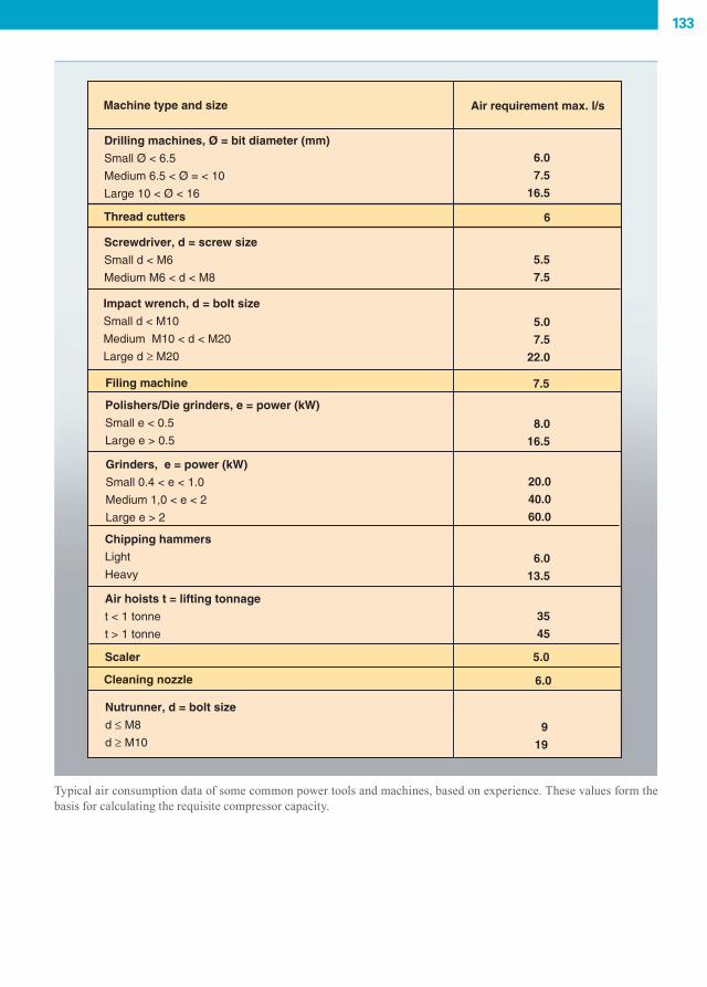
133
Typical air consumption data of some common power tools and machines, based on experience. These values form the basis for calculating the requisite compressor capacity.
CAM_edition8_2014.indd 133 13/04/15 14:53

134
Water content in the air at different dew points.
CAM_edition8_2014.indd 134 13/04/15 14:54

135
6.4 COMPILATION OF APPLICABLE STANDARDS AND REGULATIONS
6.4.1 GeneralIn the compressed air sector, as in many other industrial sectors, regulations apply. They may include requirements that are defined by legisla-tion as well as optional regulations or recommen-dations, as for national and international standards. Sometimes regulations in standards may become binding when they come into force through leg-islation. If a standard is quoted in a commercial agreement it can thereby also be made binding.Binding regulations can apply, for example, to safety for people and property while optional stan-dards are used to facilitate work with specifica-tions, selection of quality, performing and report-ing measurements, manufacturing drawings etc.
6.4.2 StandardsThe benefits of international standardization are obvious to both manufacturers, intermediate parties such as engineering companies and final customers. It increases the interchangeability of products and systems, and allows performance statements to be compared on equal terms. These performance statements may include operational, environmental and safety aspects.Standards are referred to frequently by legislators as a way of creating uniform market impacts. Stan-dards may be produced, issued and maintained by standardization organizations on national, supra-national (European) and international levels, but equally by specific trade associations focusing on specific industrial sectors (the petroleum industry, compressed air industry, electronics industry etc).
Standards produced by the International Organi-zation for Standardization (ISO) may be converted into national standards by the ISO member coun-tries at their discretion. Standards produced by the CEN (European Committee for Standardization), are developed for use by the 30 national members, and conversion into national standard may be mandatory in the case of harmonized standards.
All standards can be acquired through the various national standardization organizations.
In the compressed air industry, standards may also be produced by trade associations such as PNEUROP (European committee of manufactur-ers of compressed air equipment, vacuum pumps, pneumatic tools and allied equipment), or its coun-terpart CAGI (United States Compressed Air and Gas Institute). Examples of such documents are the performance measurement standards for compres-sor capacity, oil content in the compressed air, etc. which were issued while awaiting an international standard to be developed.
6.4.3 CompilationA non-exhaustive list of current (2010) standards within the compressed air industry follows below. The listed references are both European and US. Pneurop standard initiatives are usually issued in parallel with a CAGI issue for the American mar-ket.
It is recommended to check with the issuing body to ensure that the latest edition is being used, unless the particular market requirement/demand refers to a dated issue.
6.4.3.1 Machinery safetyEU Machinery directive 2006/42/EC, referring to the following standards:
EN 1012-1 Compressors and vacuum pumps – Safety requirements
EN ISO 12100-1:2003 AMD 1 2009, Safety of Machinery – Basic concepts, General principles for design – Part 1: Basic Terminology, Methodol-ogy
EN ISO 12100-2:2003 AMD 1 2009, Safety of Machinery – Basic concepts, General principles for design – Part 2: Technical Principles
6.4.3.2 Pressure equipment safetyEU Directive 87/404/EC, Simple pressure vessels
EU Directive 97/23/EC, Pressure Equipment, referring to the following standards:
CAM_edition8_2014.indd 135 13/04/15 14:54

136
EN 764-1 to 7, Pressure equipment
EN 286-1 to 4, Simple, unfired pressure vessels designed to contain air or nitrogen
6.4.3.3 EnvironmentEU Directive 2000/14/EC, Outdoor Noise Emis-sion, referring to the following standards:
EN ISO 3744:2009, Determination of sound power levels of noise sources using sound pressure – Engineering method EN ISO 2151:2004, Noise test code for compres-sors and vacuum pumps – Engineering method
EU Directive 2004/26/EC, Emission standard for non-road engines – Stage III levels implemented from 2006 to 2013, Stage IV as from 2014
US Federal Emission standard for non-road engines – Tier III levels implemented from 2006 to 2008, Tier IV levels as from 2008 to 2015
6.4.3.4 Electrical safetyEU Directive 2004/108/EC, Electromagnetic com-patibility, referring to the following standards:
EN 61000-6-2:2005, Electromagnetic compatibil-ity (EMC) - PART 6-2: Generic Standards - Immu-nity for Industrial Environments
EN 61000-6-4:2006, Electromagnetic compatibil-ity (EMC) - PART 6-4: Generic Standards – Emis-sion standards for Industrial Environments
EU Directive 2006/95/EC, Low Voltage Equip-ment, referring to following standards:
EN 60034- Part 1 to 30, Rotating Electrical Machines – Rating and Performance
EN 60204-1:2009, Safety of Machinery - Elec-trical Equipment of Machines – Part 1: General Requirements
EN 60439-1:2004, Low-voltage switchgear and control gear assemblies – Part 1: Type tested and partially type tested assemblies
6.4.3.5 Medical devices – generalEU Directive 93/42/EC, referring to the following standards:
EN ISO 13485:2000, Plastics Piping system – Test method for leak-tightness under internal pressure
EN ISO 14971:2007, Medical Devices – Applica-tion of risk management to Medical Devices
6.4.3.6 StandardizationISO 3857-1:1977, Compressors, pneumatic tools and machines - Vocabulary - Part 1: General
ISO 3857-2:1977, Compressors, pneumatic tools and machines - Vocabulary - Part 2: Compressors
ISO 5390:1977, Compressors - Classification
6.4.3.7 Specifications and testingISO 1217:2009, Displacement compressors – Acceptance tests
ISO 5389:2005, Turbo-compressors - Performance test code
ISO 7183:2007, Compressed air dryers - Specifica-tions and testing
ISO 12500:2007-Part 1 to 3, Filters for Compressed Air – Test Methods
ISO 8573-Part 1 to 9, Compressed Air - Contami-nants and purity classes – Test Methods
CAM_edition8_2014.indd 136 13/04/15 14:54

137
CAM_edition8_2014.indd 137 13/04/15 14:54

INDEX
Aabsolute pressure 1.2.1absolute zero 1.2.2absorption 2.4.1absorption dryers 2.4.1.4activated carbon 3.2.9active power 1.6.4adsorption 2.4.1adsorption dryers 2.4.1.5after cooler 2.4.1.1, 3.2.6air 1.4air-borne energy recovery 3.4.3.2air composition 1.4.1air consumption 1.1.2, 4.2.3air cooled compressor 3.3.2air receiver 3.6.1.1air requirement 3.1.1.2air treatment 3.2alternating current 1.6.1apparent power 1.6.4atmospheric pressure 1.2.1atomic number 1.1.1axial compressors 2.2.3
Bbooster compressors 2.3.2Boyle’s law 1.3.2bypass regulation 2.5.2.2 Ccables 3.7.6capacitive measurement system 2.5.5.2carbon filter 2.4.2, 3.2.5Celsius scale 1.2.2central control 2.5.7centralized installation 3.1.2.2centrifugal compressors 2.2.2changes in state 1.3.4Charles’ law 1.3.2circuit-breaker 3.7.5clearance volume 1.5.3closed cooling system 3.3.1.4 compressed air central 3.5.1, 3.5.2, 3.5.3compressed air distribution 3.6.1compressed air quality 3.2.2
compresson in several stages 1.5.5compressor calculation 4.3.2compressor central 3.1.2, 3.5compressor package 3.5.1conductivity 1.3.3contactor 3.7.3continuous capacity regulation 2.5.1control and monitoring 2.5.4convection 1.3.3cooling methods 1.6.5.5, 3.3cost allocation 4.1.1.1, 4.3.2critical pressure ratio 1.3.5.
Ddata monitoring 2.5.5decentralized installations 3.1.2.3decibel 3.8.1degree of recovery 3.4.2, 4.2.6delta connection 1.6.5.7.dew point 1.4.2diaphragm compressors 2.1.4diaphragm filter 3.2.8dimensioning 3.1.3, 3.1.5.1direct start 3.7.3displacement compressors 1.5.2, 2.1.1double acting compressors 1.5.2, 2.1.2drawing symbols 6.2drying 2.4.1dynamic compressors 1.5.4., 2.2.1
Eelectric motor 1.6.5electrical current 1.6.1electrical voltage 1.6.1electricity 1.6electromotive force (emf) 1.6.2electrons 1.1.1energy recovery 3.4equivalent pipe length 3.6.3exhaust emissions 2.6.2
FFAD 1.2.6filter 2.4.2, 3.2.5filter efficiency 2.4.2flow through pipes 1.3.6frequency 1.6.1frequency converter 2.5.4.3fuses 3.7.5
CAM_edition8_2014.indd 138 13/04/15 14:54

Ggas constant 1.3.2gas laws 1.3.2gradual start 3.7.3
Hheat exchanger 5.7.1, 5.7heat tranfer 1.3.3high pressure compressor 3.6.1.1high voltage 1.6.1
Iidling time 2.5.4.2impedance 1.6.2individual gas constant 1.3.2inlet regulation 2.5.3.1installation’s overall economy 4.1.1.1insulation class 1.6.5.3intake air 3.5.4intake pressure variation 3.1.3.2isentropic process 1.3.4.4ISO 6.4isobaric process 1.3.4.2isochoric process 1.3.4.1isothermal process 1.3.4.3
JJoule-Thomson effect 1.3.7
KKelvin scale 1.2.2
Llaminar flow 1.3.6leakage 3.1.1.3, 4.2.3life cycle cost, LCC 4.3liquid injected screw compressors 2.1.5.2loading 2.5.1logarithmic mean temperature difference 1.3.3low voltage 1.6.1
Mmain voltage 1.6.3maintenance costs 4.2.7maintenance planning 4.2.7.1MD dryer 2.4.1.5medical air 3.2.9membrane dryers 2.4.1.6
metal resistor 2.5..1micro-organisms 3.2.4mobile compressors 2.6modulation 2.5.3.4moist air 1.4.2molecular movement 1.1.2molecules 1.1.1monitoring 2.5.5.3, 2.5.8multi-stage off loading 2.5.2.8
Nneutrons 1.1.1new investment 4.1.1.1noise 3.8.9non-sinusoidal waveforms 1.6.1normal litre 1.2.6nozzle 1.3.5
Ooff loading/loading 2.5.1Ohm’s law 1.6.2oil filter 3.2.5oil-free compressors 2.1.3oil-free screw compressors 2.1.5.1oil temperature control 2.6.3oil/water separation 3.2.8open cooling system 3.3.1.2, 3.3.1.3operating analysis 3.1.1.3operating costs 4.1.1.1, 4.1.1.2optimised compressor operations 4.1.1.1outlet regulation 2.5.3.2over compression 2.4.1.3overall cost 4.3.2overload protection 3.7.5
Ppart flow measurement 3.6.4particle filter 2.4.2phase compensation 3.7.7phase displacement 1.6.2phase voltage 1.6.3pipe resonance 3.5.4pipes 1.3.3piston compressors 1.5.1, 1.5.2, 2.1.2plasma 1.1.2polytropic process 1.3.4.5power 1.2.5, 1.6.4.Power Factor 1.6.4prefilter 3.5.4
CAM_edition8_2014.indd 139 13/04/15 14:54

pressure 1.2.1pressure intensifier 2.3.3pressure band 2.5.4.2pressure dew point 2.4.1pressure drop 1.3.6, 4.2.2pressure measurement 1.2.1, 2.5.5.2pressure ratio 1.5.2pressure relief 2.5.2.1, 2.5.3.4pressure relief with throttled intake 2.5.2.4pressure switch 2.5.4.2protection classes 1.6.5.4protons 1.1.1
Qquality class in accordance with ISO 3.2.2quantity of ventilation air 3.5.5
Rradial compressors 2.1.1, 2.2.2radiation 1.1.1reactance 1.6.2reactive power 1.6.4recovery potential 3.4.2, 4.2.6refrigerant dryer 2.4.1.2regulation 2.5.1regulation system 2.5.1remote monitoring 2.5.8resistance 1.6.2resistance thermometer 2.5.5.1resistive measurement system 2.5.5.2reverbation 3.8.4Reynolds’ number 1.3.6ring piping 3.6.2room constant 3.8.3roots blowers 2.1.9
Ssaving possibilities 4.2screw compressors 2.15scroll compressors 2.1.7separation efficiency 2.4.2sequence control 2.5.6.1short-circuit protection 3.7.5single acting compressor 1.5.2, 2.1.2SI-system 6.1sound 3.8sound absorption 3.8.8sound dampening 3.8.8sound measurements 3.8.6
sound power level 3.8.1sound pressure level 3.8.1speed regulation 2.5.2.6, 2.5.4.3standards 6.4star connection 1.6.3, 1.6.5.7star/delta start 3.7.3start sequence selector 2.5.6.1start/stop regulation 2.5.2.5starter 3.7.3, 3.7.5sterile filters 3.2.5stroke volume 1.5.3suction valve unloading 2.5.2.8synchronous speed 1.6.5.1
Ttables 6.3temperature 1.2.2temperature measurement 2.5.5.1thermal capacity 1.2.3thermal conductivity number 1.3.3thermistor 2.5.5.1thermodynamics 1.3three phase system 1.6.3throttling 1.3.7throttling the inlet 2.5.2.3tooth compressor 2.1.6torque 1.6.5.8turbo compressor 2.2.1turbulent flow 1.3.6twin screw compressors 2.1.5types of compressors 1.5
Vvacuum pomps 2.3.1valve off-loading 2.5.2.8vane compressors 2.1.8vane regulation 2.5.3.2, 2.5.3.3variable discharge port 2.5.2.7ventilation fan 3.5.5volume rate of low 1.2.6
Wwater content in compressed air 2.4.1, 3.2.2water cooled compressor 3.3.1water separator 2.4.1.1water vapor 3.2.2 water-borne energy recovery 3.4.3.3work 1.2.4working pressure 3.1.1.1
CAM_edition8_2014.indd 140 13/04/15 14:54

NOTES
CAM_edition8_2014.indd 141 13/04/15 14:54

CAM_edition8_2014.indd 142 13/04/15 14:54

CAM_edition8_2014.indd 143 13/04/15 14:54

CAM_edition8_2014.indd 144 13/04/15 14:54


ATLAS COPCO COMPRESSED AIR MANUAL
8th editionCom
pressed Air M
anual 8th edition
www.atlascopco.comBelgium, 2015, 9780 0380 11
CAM_cover_English_2014.indd 1 13/04/15 14:54


![[Atlas Copco] Compressed Air Manual(Bookos.org)](https://static.fdocuments.in/doc/165x107/577cc7611a28aba711a0c4b5/atlas-copco-compressed-air-manualbookosorg.jpg)