ATEX - Intrinsically Safe
6
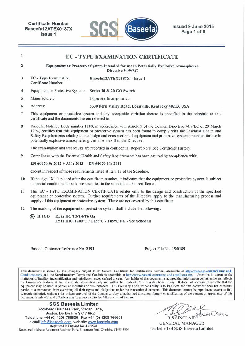
Certificate Number Baseefa12ATEX0187X Issue 1 Issued 9 June 2015 Page 1 of 6 1 EC - TYPE EXAMINATION CERTIFICATE 2 Equipment or Protective System Intended for use in Potentially Explosive Atmospheres Directive 94/9/EC 3 EC - Type Examination Baseefa12ATEX0187X - Issue 1 Certificate Number: 4 Equipment or Protective System: Series 10 & 20 GO Switch 5 Manufacturer: Topworx Incorporated 6 Address: 3300 Fern Valley Road, Louisville, Kentucky 40213, USA 7 This equipment or protective system and any acceptable variation thereto is specified in the schedule to this certificate and the documents therein referred to. 8 Baseefa, Notified Body number 1180, in accordance with Article 9 of the Council Directive 94/9/EC of 23 March 1994, certifies that this equipment or protective system has been found to comply with the Essential Health and Safety Requirements relating to the design and construction of equipment and protective systems intended for use in potentially explosive atmospheres given in Annex II to the Directive. The examination and test results are recorded in confidential Report No's. See Certificate History 9 Compliance with the Essential Health and Safety Requirements has been assured by compliance with: EN 60079-0: 2012 + All: 2013 EN 60079-11: 2012 except in respect of those requirements listed at item 18 of the Schedule. 10 If the sign "X" is placed after the certificate number, it indicates that the equipment or protective system is subject to special conditions for safe use specified in the schedule to this certificate. 11 This EC - TYPE EXAMINATION CERTIFICATE relates only to the design and construction of the specified equipment or protective system. Further requirements of the Directive apply to the manufacturing process and supply of this equipment or protective system. These are not covered by this certificate. 12 The marking of the equipment or protective system shall include the following: @ II1GD Ex ia IIC T3/T4/T6 Ga Ex ia IIIC T2000C 1 T135°C 1 T85°C Da - See Schedule Baseefa Customer Reference No. 2191 Project File No. 15/0189 This document is issued by the Company subject to its General Conditions for Certification Services accessible at http://www.sgs.com/en/Terms-and- Conditions.aspx and the Supplementary Terms and Conditions accessible at http://www.baseefa.com/terms-and-conditions.asp. Attention is drawn to the limitation of liability, indemnification and jurisdiction issues defined therein. Any holder of this document is advised that information contained herein reflects the Company's findings at the time of its intervention only and within the limits of Client's instructions, if any. It does not necessarily indicate that the equipment may be used in particular industries or circumstances. The Company's sole responsibility is to its Client and this document does not exonerate parties to a transaction from exercising all their rights and obligations under the transaction documents. This document cannot be reproduced except in full, schedule included, without prior written approval of the Company. Any unauthorized alteration, forgery or falsification of the content or appearance of this document is unlawful and offenders may be prosecuted to the fullest extent of the law. SGS Baseefa Limited Rockhead Business Park, Staden Lane, Buxton, Derbyshire SK17 9RZ Telephone +44 (0) 1298 766600 Fax +44 (0) 1298 766601 e-mail [email protected] web site www.baseefa.com Registered in England No. 4305578. Registered address: Rossmore Business Park, Ellesmere Port, Cheshire, CH65 3EN -- {f R S SINCLAIR GENERAL MANAGER On behalf of SGS Baseefa Limited
Transcript of ATEX - Intrinsically Safe
Certificate NumberBaseefa12ATEX0187X
Issue 1
Issued 9 June 2015Page 1 of 6
1 EC - TYPE EXAMINATION CERTIFICATE
2 Equipment or Protective System Intended for use in Potentially Explosive AtmospheresDirective 94/9/EC
3 EC - Type Examination Baseefa12ATEX0187X - Issue 1Certificate Number:
4 Equipment or Protective System: Series 10 & 20 GO Switch
5 Manufacturer: Topworx Incorporated
6 Address: 3300 Fern Valley Road, Louisville, Kentucky 40213, USA
7 This equipment or protective system and any acceptable variation thereto is specified in the schedule to thiscertificate and the documents therein referred to.
8 Baseefa, Notified Body number 1180, in accordance with Article 9 of the Council Directive 94/9/EC of 23 March1994, certifies that this equipment or protective system has been found to comply with the Essential Health andSafety Requirements relating to the design and construction of equipment and protective systems intended for use inpotentially explosive atmospheres given in Annex II to the Directive.
The examination and test results are recorded in confidential Report No's. See Certificate History
9 Compliance with the Essential Health and Safety Requirements has been assured by compliance with:
EN 60079-0: 2012 + All: 2013 EN 60079-11: 2012
except in respect of those requirements listed at item 18 of the Schedule.
10 If the sign "X" is placed after the certificate number, it indicates that the equipment or protective system is subjectto special conditions for safe use specified in the schedule to this certificate.
11 This EC - TYPE EXAMINATION CERTIFICATE relates only to the design and construction of the specifiedequipment or protective system. Further requirements of the Directive apply to the manufacturing process andsupply of this equipment or protective system. These are not covered by this certificate.
12 The marking of the equipment or protective system shall include the following:
@ II1GD Ex ia IIC T3/T4/T6 GaEx ia IIIC T2000C 1T135°C 1T85°C Da - See Schedule
Baseefa Customer Reference No. 2191 Project File No. 15/0189
This document is issued by the Company subject to its General Conditions for Certification Services accessible at http://www.sgs.com/en/Terms-andConditions.aspx and the Supplementary Terms and Conditions accessible at http://www.baseefa.com/terms-and-conditions.asp. Attention is drawn to thelimitation of liability, indemnification and jurisdiction issues defined therein. Any holder of this document is advised that information contained herein reflectsthe Company's findings at the time of its intervention only and within the limits of Client's instructions, if any. It does not necessarily indicate that theequipment may be used in particular industries or circumstances. The Company's sole responsibility is to its Client and this document does not exonerateparties to a transaction from exercising all their rights and obligations under the transaction documents. This document cannot be reproduced except in full,schedule included, without prior written approval of the Company. Any unauthorized alteration, forgery or falsification of the content or appearance of thisdocument is unlawful and offenders may be prosecuted to the fullest extent of the law.
SGS Baseefa LimitedRockhead Business Park, Staden Lane,
Buxton, Derbyshire SK17 9RZTelephone +44 (0) 1298 766600 Fax +44 (0) 1298 766601
e-mail [email protected] web site www.baseefa.comRegistered in England No. 4305578.
Registered address: Rossmore Business Park, Ellesmere Port, Cheshire, CH65 3EN
--
{fA-LUh\~t:NR S SINCLAIR
GENERAL MANAGEROn behalf of SGS Baseefa Limited
Certificate NumberBaseefa12ATEX0187X
Issue 1
13 Schedule
Issued 9 June 2015Page 2 of6
14 Certificate Number Baseefa12ATEX0187X - Issue 1
15 Description of Equipment or Protective System
The Series 10 & 20 GO Switch are a range of magnetically operated switches which are actuated by the presence of anexternal ferrous body. The range includes a number of different switch configurations with single pole, double throw ordouble pole, double throw switches within a switch body.
The switches comprise a rectangular stainless steel or lacquered brass enclosure housing the switch mechanism sealed inthe top of the enclosure with the sensing magnets located below. These, and the integral connections to the switchmechanism are potted in the enclosure with external connections to the switch made by a threaded entry on the side orbottom of the switch enclosure. The switch is mounted in place using two mounting points that pass through the enclosure.
The switches are rated up to 30V peak a.c. or d.c., 0.25A and may be used to switch a circuit from a certified Ex ia IICintrinsically safe source. Both sides of each double throw switch and each pole of a double pole switch, within oneproximity switch, must form part of the same intrinsically safe circuit. The switched circuit is capable of withstanding a500V test to earth.
The Series 10 & 20 GO Switch are available with a number of different switch configurations, sensing range and externalconnection outlet positions, all with either screw terminals, plug and socket or integral lead external connection options.When fitted with the integral leads, the external connections must be terminated within an enclosure provided withprotection suitable for the zone of installation. The only difference between the Series 10 and 20 variants is the dimensionsof the switch enclosure. In terms of intrinsic safety, all variants of the Series 10 & 20 switches are identical with exceptionof the potting used on the 'H' high temperature variants is suitable for the higher ambient temperature.
The Series 10 & 20 GO Switch model ranges covered by this certificate are defined on the next pages:-
Certificate NumberBaseefa12ATEX0187X
Issue 1
Issued 9 June 2015Page 3 of 6
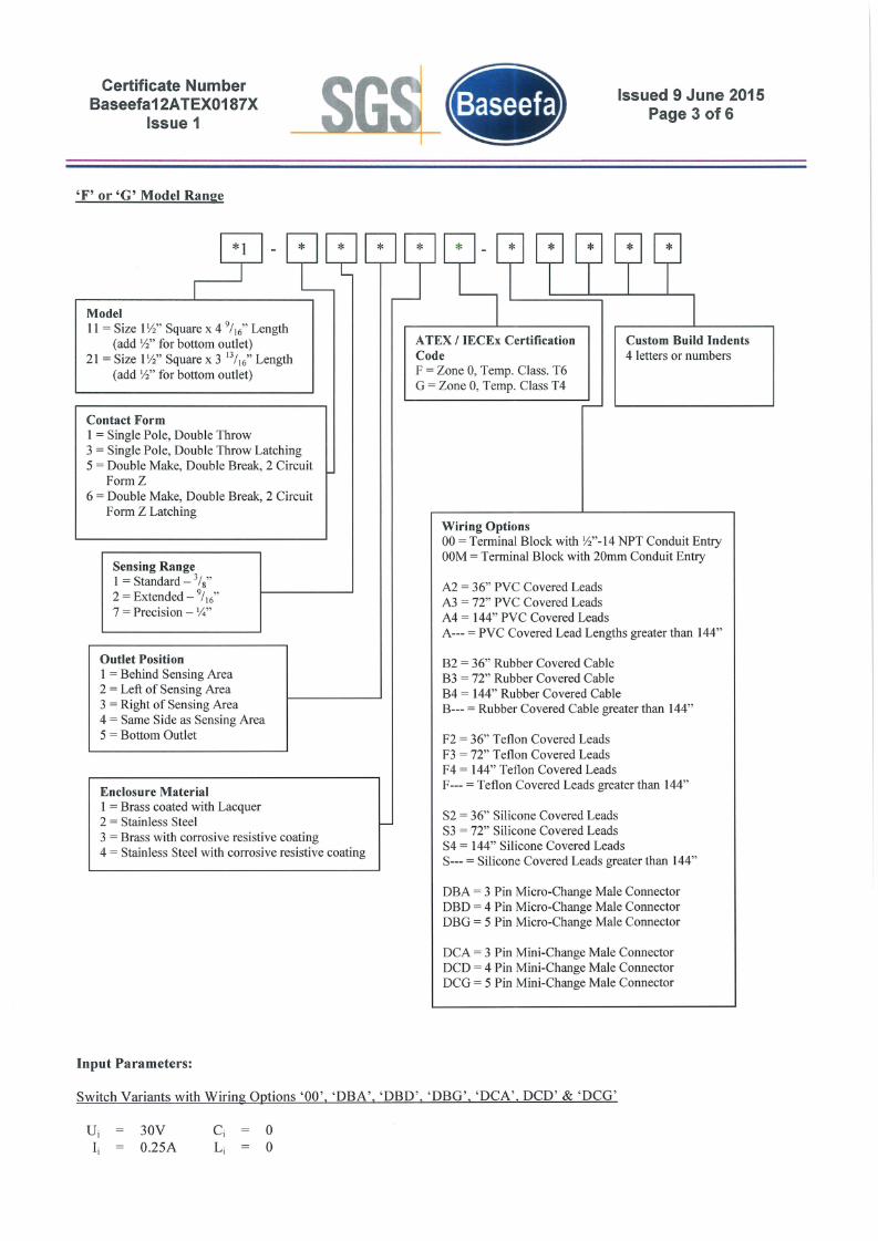
'F' or 'G' Model Range
Custom Build Indents4 letters or numbers
ATEX / IECEx CertificationCodeF = Zone 0, Temp. Class. T6G = Zone 0, Temp. Class T4
Model11 = Size 1~" Square x 4 9/16" Length
(add ~" for bottom outlet)21 = Size 1~" Square x 3 13/16" Length
(add ~"for bottom outlet)
Contact Form1 = Single Pole, Double Throw3 = Single Pole, Double Throw Latching5 = Double Make, Double Break, 2 Circuit
FormZ6 = Double Make, Double Break, 2 Circuit
Form Z Latching
Sensing Range1 = Standard - 3/8"
2 = Extended - 9/16"
7 = Precision - 14"
Wiring Options00 = Terminal Block with ~"-14 NPT Conduit EntryOOM = Terminal Block with 20mm Conduit Entry
A2 = 36" PVC Covered LeadsA3 = 72" PVC Covered LeadsA4 = 144" PVC Covered LeadsA--- = PVC Covered Lead Lengths greater than 144"
Outlet Position1 = Behind Sensing Area2 = Left of Sensing Area3 = Right of Sensing Area4 = Same Side as Sensing Area5 = Bottom Outlet
Enclosure Material1 = Brass coated with Lacquer2 = Stainless Steel3 = Brass with corrosive resistive coating4 = Stainless Steel with corrosive resistive coating
B2 = 36" Rubber Covered CableB3 = 72" Rubber Covered CableB4 = 144" Rubber Covered CableB--- = Rubber Covered Cable greater than 144"
F2 = 36" Teflon Covered LeadsF3 = 72" Teflon Covered LeadsF4 = 144" Teflon Covered LeadsF--- = Teflon Covered Leads greater than 144"
S2 = 36" Silicone Covered LeadsS3 = 72" Silicone Covered LeadsS4 = 144" Silicone Covered LeadsS--- = Silicone Covered Leads greater than 144"
DBA = 3 Pin Micro-Change Male ConnectorDBD = 4 Pin Micro-Change Male ConnectorDBG = 5 Pin Micro-Change Male Connector
DCA = 3 Pin Mini-Change Male ConnectorDCD = 4 Pin Mini-Change Male ConnectorDCG = 5 Pin Mini-Change Male Connector
Input Parameters:
Switch Variants with Wiring Options '00', 'DBA', 'DBD', 'DBG', 'DCA', DCD' & 'DCG'
30V0.25A
oo
Certificate NumberBaseefa12ATEX0187X
Issue 1
Issued 9 June 2015Page 4 of6
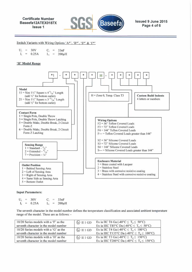
Switch Variants with Wiring Options 'A*', 'B*', 'S*' & 'F*'
30V0.25A
33nF200flH
'H' Model Range
Custom Build Indents4 letters or numbers
H = Zone 0, Temp. Class T3
Model11 = Size l1i" Square x 4 9/16" Length
(add 1i" for bottom outlet)21 = Size l1i" Square x 3 13/16" Length
(add 1i" for bottom outlet)
Contact Form1 = Single Pole, Double Throw3 = Single Pole, Double Throw Latching5 = Double Make, Double Break, 2 Circuit
FormZ6 = Double Make, Double Break, 2 Circuit
Form Z Latching
Wiring OptionsF2 = 36" Teflon Covered LeadsF3 = 72" Teflon Covered LeadsF4 = 144" Teflon Covered LeadsF--- = Teflon Covered Leads greater than 144"
Sensing Range1 = Standard - 3/8"
2 = Extended - 9/16"
7 = Precision - 1;4"
S2 = 36" Silicone Covered LeadsS3 = 72" Silicone Covered LeadsS4 = 144" Silicone Covered LeadsS--- = Silicone Covered Leads greater than 144"
Outlet Position1 = Behind Sensing Area2 = Left of Sensing Area3 = Right of Sensing Area4 = Same Side as Sensing Area5 = Bottom Outlet
Enclosure Material1 = Brass coated with Lacquer2 = Stainless Steel3 = Brass with corrosive resistive coating4 = Stainless Steel with corrosive resistive coating
Input Parameters:
30V0.25A
33nF200flH
The seventh character in the model number defines the temperature classification and associated ambient temperaturerange of the model. These are as follows: -
10/20 Series models with a 'F' as the 10 II 1 GD Ex ia IIC T6 Ga (-40°C:S Ta:S 50°C)seventh character in the model number Ex ia IIIC T85°C Da (-40°C:S Ta:S 50°C)10/20 Series models with a 'G' as the 10IIIGD Ex ia IIC T4 Ga (-40°C:S Ta:S 100°C)seventh character in the model number Ex ia IIIC T135°C Da (-40°C:S Ta:S 100°C)10/20 Series models with a 'H' as the 10 II 1 GD Ex ia IIC T3 Ga (-40°C:S Ta:S 150°C)seventh character in the model number Ex ia IIIC T200°C Da (-40°C:S Ta:S 150°C)


Certificate NumberBaseefa12ATEX0187X
Issue 1
Issued 9 June 2015Page 6 of 6
Number Sheet Issue Date Description
S-SI0-0070 1 of 1 11 12/15/04 10 Series Enclosure for Models: 10- xx 2 or 3 xx - xx
S-SI0-0080 1 of 1 10 5/7/07 Go Switch 10 Series Enclosure (Brass)
S-S 10-0190 1 of 1 11 5/14/2012 Number 5 in 4th Group S.S. Body Tube with Model
S-S 10-0191 1 of 1 15 5/14/2012 S.S. Body Tube with Conduit Hole in StandardPosition with Model Number 1 or 4 in 4 th Group
S-SI0-0192 1 of 1 15 5/14/2012 S.S. Body Tube with Conduit Hole with ModelNumbers 2 or 3 in 4th Group
S-S20-0221 1 of 1 14 5/14/12 S.S. Body Tube for 20 Series Switch
S-S20-0222 1 of 1 12 5/14/12 S.S. Body Tube for 20 Series Switch with 4th DigitNumber 2 or 3
S-S20-0223 1 of 1 13 5/14/12 S.S. Body Tube for 20 Series Switch with BottomConduit Outlet
S-S20-0257 1 of 1 10 12/16/04 20 Series Enclosure (Brass) for Models: 21 - xx - 1 or4 xx-xx
S-S20-0258 1 of 1 10 12/16/04 20 Series Enclosure (Brass) for Models: 21 - xxx 2 or3 x-xx
S-S20-0259 1 of 1 13 02/05/09 Go Switch 20 Series Enclosure (Brass)
The above drawings are associated and held with IECEx Certificate No. IECEx BAS 12.0106X
20 Certificate History
Certificate No.
Baseefa12ATEX0187X
Baseefa02ATEX023 5XIssue 1
Date
8 January 2013
9 June 2015
Comments
The release of the prime certificate. The associated test andassessment is documented in Certification Report No.GB/BAS/ExTRI2.0238/00.
i) To permit the equipment name to be changed from Series 10 and20 Leverless Limit Switches to Series 10 & 20 GO Switches. TheEquipment Title and Certificate Schedule were revised to list the newname. This change does not affect the original assessment.
ii) To permit the addition of variants of the Series 10 & 20 GOSwitches fitted with a silicone covered cable. The fitting of thesilicone cable does not affect input parameters and previous test andassessment of the equipment. The certificate schedule have beenupdated to list the new variants denoted by an'S' in the modelnumber.
iii) To permit the minimum ambient temperature of the 'F' models tobe changed from -20°C to -40°C. This change does not affect theoriginal assessment.
iv) To permit minor drawing changes not affecting the originalassessment.
v) To confirm the current design of all variants of the Series 10 & 20GO Switches were reviewed against the requirements ofEN 60079-0: 2012 + All: 2013 in respect of the differences fromEN 60079-0: 2012, and none of the differences affect the equipment.The standards listed on page 1 of the certificate were updated.
The above test and assessment is documented in IECEx ExTR No.GB/BAS/ExTRI5.0139/00.
For drawings applicable to each issue, see original of that issue.