ATEX instruction for OMS - whitedriveproducts.com
24
Technical Information ATEX instruction for OMS
Transcript of ATEX instruction for OMS - whitedriveproducts.com

Technical InformationATEX instruction for OMS


Contents
Chapter 1: General Information..............................................................................5ATEX introduction................................................................................................................................................6Explosive atmosphere............................................................................................................................................6
Explosion triangle......................................................................................................................................6General zone classification........................................................................................................................6Equipment category and zones..................................................................................................................7Marking of motors.....................................................................................................................................8
Chapter 2: Maximum surface temperature for OMS..........................................11
Chapter 3: Versions and code numbers................................................................ 13OMS motors........................................................................................................................................................ 14
Chapter 4: Technical specifications.......................................................................15Technical specification for OMS motors............................................................................................................ 16Ambient temperature...........................................................................................................................................16Oil types / Operating fluids................................................................................................................................. 16
Mineral oils for OMS motors.................................................................................................................. 16Oil temperature........................................................................................................................................16Viscosity..................................................................................................................................................17Filtering................................................................................................................................................... 17
Chapter 5: Cross list............................................................................................... 19OMS motor cross list...........................................................................................................................................20
Chapter 6: Declaration........................................................................................... 23
ATEX certified motors | Contents | iii


Chapter
1General Information
Topics:
• ATEX introduction• Explosive atmosphere

ATEX introductionHydraulic Orbital Motors are designed for mobile and stationary applications. Some motors are used in relatedapplications, where locations are classified as hazardous areas.
The ATEX Directive 2014/34/EU specifies the minimum safety requirements for equipment intended for use inpotentially explosive atmospheres in European Union member states. ATEX is derived from the French term“ATmosphères EXplosives”.
The equipment intended for use in hazardous areas are divided into two groups:
Group I: Equipment intended for use in underground parts of mines (mining equipment).
Group II: Equipment intended for use in other places than mines (non-mining equipment).
The hydraulic orbital motors are intended for use in Group II applications.
Explosive atmosphere
Explosion triangleA “hazardous area” is defined as an area in which the atmosphere contains, or may contain in sufficient quantities,flammable or explosive gases, dusts or vapours. In such an atmosphere a fire or explosion is possible when three basicconditions are met. This is often referred to as the “hazardous area” or “explosion” triangle.
Ignitablesubstance (Gas)
Oxygen Source of ignition(Spark or heat)
P301 800
An atmosphere with the potential to become an explosive atmosphere during operating conditions and/or under theinfluence of the surroundings is defined as a potentially explosive atmosphere. Products covered by directive2014/34/EU are defined as intended for use in potentially explosive atmospheres. Removing one of the elementseliminates all risk of explosion.
General zone classificationDirective 99/92/EC divides the Hazardous areas into zones and defines criteria by which products are categorizedwithin these zones; Zone 0 / 20 is the most restrictive and Zones 1 / 21 and 2 / 22 are less restrictive. The followingtable describes the zones in an installation where there is a potential for explosive atmospheres. The owner of theinstallation must analyze and assess the area in which the explosive gas/dust mixture may occur, and if necessarymust divide it into zones. This process of zoning then allows the correct plant and equipment to be selected for use inthe area.
ATEX certified motors | General Information | 6

Zone 0
Zone 0
Zone 2
Zone 1
F301 801
Zones Presence of potentially explosive atmosphere Type of risk
Gas (G) Dust (D)
0 20 Present continuously or for long periods Permant
1 21 Likely to occur in normal operation occasionally Potential
2 22 Not likely to occur in normal operation but. If it doesoccur, will persist for a short period of time
Minimal
Equipment category and zonesMechanical components with potential ignition sources e.g. components containing non-conductive materials orlayers or components with hot surface are covered by the ATEX-directive.
Non-mining equipment for potentially explosive atmosphere is classified as:
Equipment Group II – this group comprises three categories according to the level of safety provided:
• Category 1• Category 2• Category 3
Category 1 equipment has the highest degree of protection – see the following below.
Degree of protection Protection Category
Very high Two independent protection measures or safe if two errors occur independently Category 1
High Safe in normal operation and in anticipated case of commonly occurring errors
Category 2
Normal Safe in normal operation Category 3P301 802
These products have to fulfil all requirements in the ATEX directive, and have to be marked with the required “Ex”marking.
Equipment located in zone specified areas must fulfil the following requirements (see also the following figure):
• Category 3 – approved equipment can be installed in hazardous areas zone 2 / 22 and outside zone categorizedareas.
• Category 2 – approved equipment can be installed in hazardous areas zone 1 / 21, zone 2 / 22 and outside zonecategorized areas.
• Category 1 – approved equipment can be installed in hazardous areas zone 0 / 20, zone 1 / 21, zone 2 / 22 andoutside zone categorized areas.
ATEX certified motors | General Information | 7
Zone 0Zone 1Zone 2No requirementsts
Hazards area
Catagory3
Catagory2
Catagory1
ATEX Directive
Equipmentgroup II
P301 803
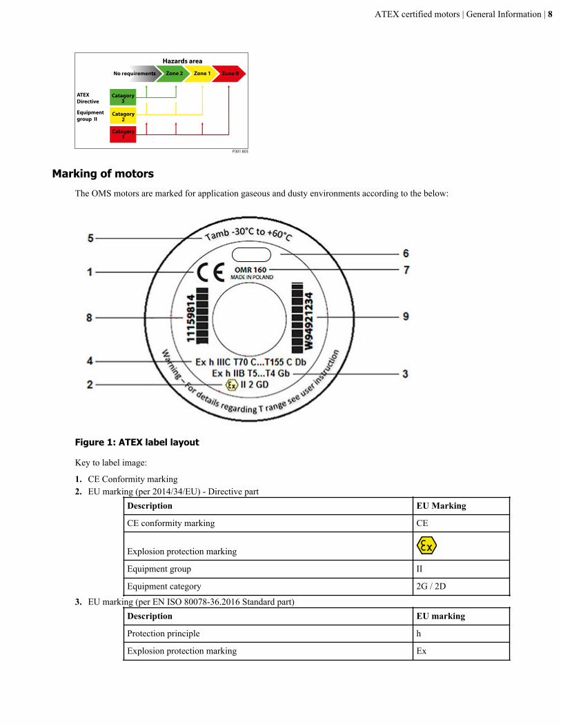
Marking of motorsThe OMS motors are marked for application gaseous and dusty environments according to the below:
Figure 1: ATEX label layout
Key to label image:
1. CE Conformity marking2. EU marking (per 2014/34/EU) - Directive part
Description EU Marking
CE conformity marking CE
Explosion protection marking
Equipment group II
Equipment category 2G / 2D
3. EU marking (per EN ISO 80078-36.2016 Standard part)Description EU marking
Protection principle h
Explosion protection marking Ex
ATEX certified motors | General Information | 8

Description EU marking
Equipment group II / III
Equipment protection level (EPL) Gb / Db
T-classGas T5...T4
Dust T70°C...T155°CTable 1: EPL/Equipment category
Definition Level ofprotection
Typicalzone ofapplication
EN ISO EU
EPL Group Category Group
Gasatmosphere
Very high 0 Ga II 1G II
High 1 Gb 2G
Enhanced 2 Gc 3G
Dustatmosphere
Very high 20 Da III 1D II
High 21 Db 2D
Enhanced 22 Dc 3D
4. See item 35. Min and max ambient temperature (see Maximum surface temperature for OMS on page 11)6. Manufacturer7. Motor type and displacement8. Code number9. Production number, date, and series number
Item 9 example: W94921234
W Manufacturing location (W = Wroclaw)
9 Year 2019
49 Week 49
2 Tuesday (1 = Monday)
1234 Consecutive number
ATEX certified motors | General Information | 9


Chapter
2Maximum surface temperature for OMS
Classification of maximum surface temperatures for Group IIequipmentTemperature class Maximum surface
temperature
°C [°F]
T3 200 [392]
T4 135 [275]
T5 100 [212]
Note:
For Group II with T4 classification it is acceptable that small surface areas(total areas ≥ 20 mm2 and ≤ 1000 mm2) can have surface temperature up to200 °C.
For T5 classification it is acceptable that small surface areas (total areas ≤1000 mm2) can have surface temperature up to 150 °C.
Maximum surface temperature – Dusty environment (GroupIII)Table 2: OMS motors - Maximum surface temperatures
Maximum oiltemperature
Maximum ambient temperature
≤ 20 °C [68 °F] ≤ 40 °C [104 °F] ≤ 60 °C [140 °F]
≤ 40 °C [104 °F] 115 [239] 135 [275] 155 [311]
≤ 60 °C [140 °F] 130 [266] 150 [302] 170 [338]
≤ 80 °C [176 °F] 145 [293] 165 [329] 185 [365]Table 3: OMSS motors (short motor) - Maximum surfacetemperature
Maximum oiltemperature
Maximum ambient temperature
≤ 20 °C [68 °F] ≤ 40 °C [104 °F] ≤ 60 °C [140 °F]
≤ 40 °C [104 °F] 85 [185] 95 [203] 105 [221]
≤ 60 °C [140 °F] 100 [212] 110 [230] 120 [248]
≤ 80 °C [176 °F] 115 [239] 125 [257] 135 [275]
Note: Above maximum surface temperatures are without any deposited duston the motors. The possible insulation effect of a dust layer on the surface has

to be taken into account by the safety margin to the minimum ignitiontemperature of the dust concerned. For up to 5 mm [1.97 in] layer thicknessthe safety margin is 75 °C [167 °F]. For further information please see IEC60079-14.
Warning: The above operating temperatures (ambient and oil) of themotor must be guaranteed by the end user.
Warning: It is compulsory to use oils whose inflammable degree is atleast 50K above the maximum surface temperature of the motor. Seealso Oil types / Operating fluids on page 16

Chapter
3Versions and code numbers
Topics:
• OMS motors
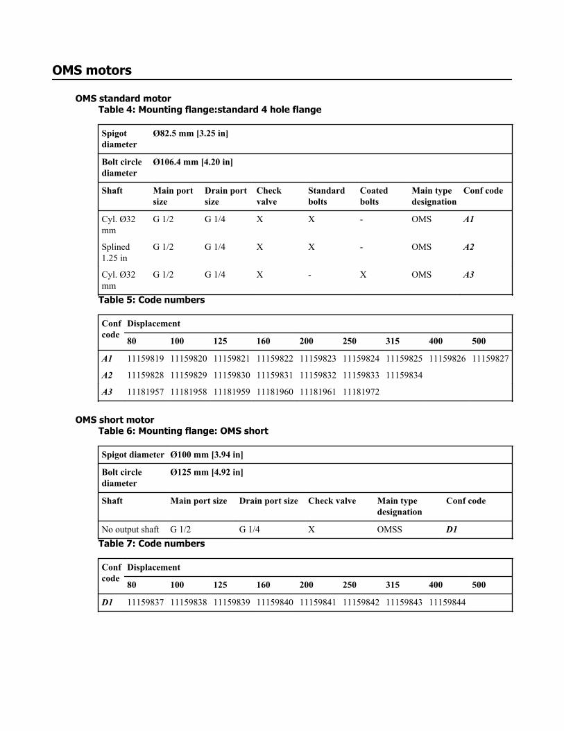
OMS motors
OMS standard motorTable 4: Mounting flange:standard 4 hole flange
Spigotdiameter
Ø82.5 mm [3.25 in]
Bolt circlediameter
Ø106.4 mm [4.20 in]
Shaft Main portsize
Drain portsize
Checkvalve
Standardbolts
Coatedbolts
Main typedesignation
Conf code
Cyl. Ø32mm
G 1/2 G 1/4 X X - OMS A1
Splined1.25 in
G 1/2 G 1/4 X X - OMS A2
Cyl. Ø32mm
G 1/2 G 1/4 X - X OMS A3
Table 5: Code numbers
Confcode
Displacement
80 100 125 160 200 250 315 400 500
A1 11159819 11159820 11159821 11159822 11159823 11159824 11159825 11159826 11159827
A2 11159828 11159829 11159830 11159831 11159832 11159833 11159834
A3 11181957 11181958 11181959 11181960 11181961 11181972
OMS short motorTable 6: Mounting flange: OMS short
Spigot diameter Ø100 mm [3.94 in]
Bolt circlediameter
Ø125 mm [4.92 in]
Shaft Main port size Drain port size Check valve Main typedesignation
Conf code
No output shaft G 1/2 G 1/4 X OMSS D1Table 7: Code numbers
Confcode
Displacement
80 100 125 160 200 250 315 400 500
D1 11159837 11159838 11159839 11159840 11159841 11159842 11159843 11159844
Chapter
4Technical specifications
Topics:
• Technical specification for OMSmotors
• Ambient temperature• Oil types / Operating fluids

Technical specification for OMS motorsAll necessary design information for instance maximum pressure rating, maximum flow, maximum radial load etc. isprovided in the Technical Information catalogues.
The rated data which we publish in our Technical Information is based on the use of premium mineral basedhydraulic oil with a viscosity of 35 mm2/s.
Ambient temperatureMaximum ambient temperature depends on the requested ATEX class needed – please see Maximum surfacetemperature for OMS on page 11.
In general, the ambient temperature should be between -30 °C [-22 °F] and +60 °C [+140 °F].
Oil types / Operating fluidsIn a hydraulic system the most important task of the oil is to transfer energy. At the same time the oil must lubricatemoving parts in hydraulic components, protect them from corrosion, and transport dirt particles and heat out of thesystem. To ensure that hydraulic components operate without problems and have long operating life it is thereforevital to select the correct oil type with the necessary additives.
Ratings and performance data are based on operating with hydraulic fluids containing oxidation, rust and foaminhibitors. These fluids must possess good thermal and hydrolytic stability to prevent wear, erosion and corrosion ofmotor components.
Mineral oils for OMS motorsFor systems containing mineral hydraulic oil with anti-wear additives, type HLP [DIN 51524] or HM (ISO 11158)must be used.
Mineral oils without anti-wear additives or engine oils can also be used, provided operating conditions are suitable.
Warning: It is compulsory to use oils whose inflammable degree is at least 50K above the maximum surfacetemperature of the motor. Maximum surface temperature can be found under:Maximum surface temperaturefor OMS on page 11.
Mixing oils of different brands or different oils of the same brand may lead to the formation of sediment and sludge.Consequently a rapid, irreversible deterioration of the system is induced.
Oil temperatureMaximum oil temperature depends on the requested ATEX class needed. See Maximum surface temperature for OMSon page 11.
Under normal operating conditions it is recommended to keep the temperature in the range of 30 °C [86 °F] to 60 °C[140 °F].
Fluid temperature affects the viscosity of the fluid and resulting lubricity and film thickness. High temperatures canalso limit seal life, at most nonmetallic materials are adversely affected by use at elevated temperatures.
Fluids may break down or oxidize at high temperature, reducing their lubricity and resulting in reduced life of theunit. Oil life is greatly reduced if its temperature exceeds +60 °C [+140 °F]. As a general rule, oil life is halved foreach 8 °C [46 °F] its temperature exceeds +60 °C [+140 °F].
ATEX certified motors | Technical specifications | 16
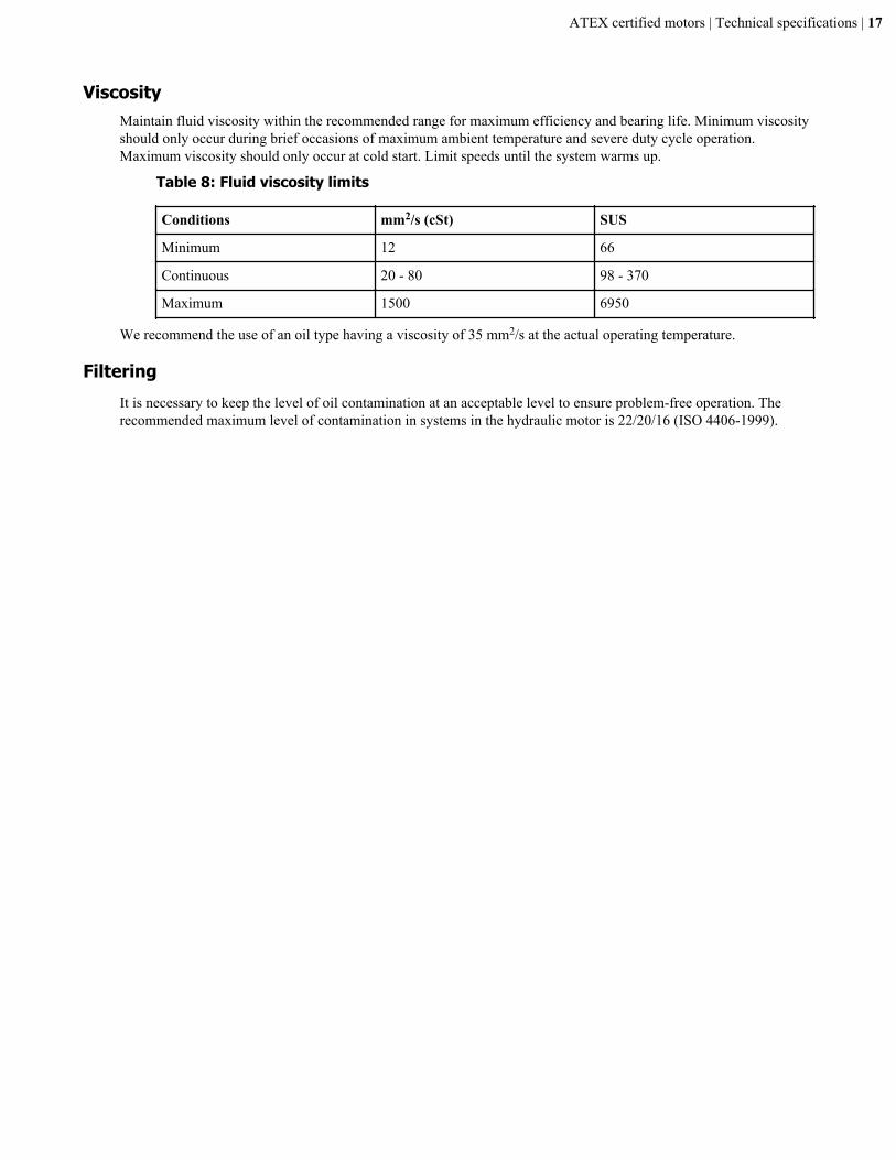
ViscosityMaintain fluid viscosity within the recommended range for maximum efficiency and bearing life. Minimum viscosityshould only occur during brief occasions of maximum ambient temperature and severe duty cycle operation.Maximum viscosity should only occur at cold start. Limit speeds until the system warms up.
Table 8: Fluid viscosity limits
Conditions mm2/s (cSt) SUS
Minimum 12 66
Continuous 20 - 80 98 - 370
Maximum 1500 6950
We recommend the use of an oil type having a viscosity of 35 mm2/s at the actual operating temperature.
FilteringIt is necessary to keep the level of oil contamination at an acceptable level to ensure problem-free operation. Therecommended maximum level of contamination in systems in the hydraulic motor is 22/20/16 (ISO 4406-1999).
ATEX certified motors | Technical specifications | 17


Chapter
5Cross list
Topics:
• OMS motor cross list
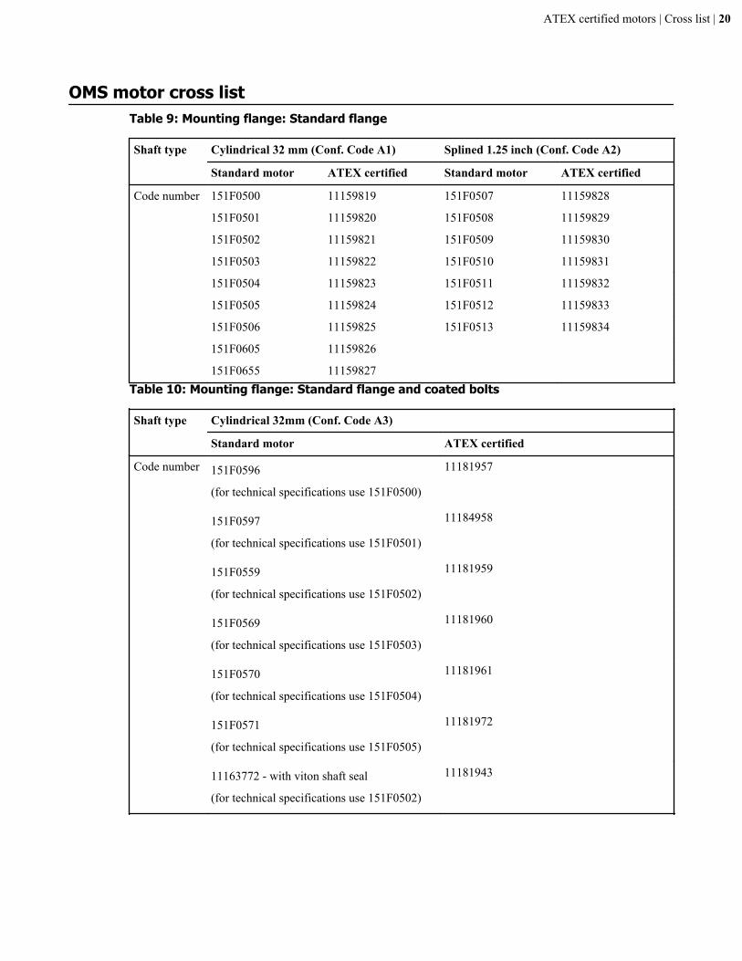
OMS motor cross listTable 9: Mounting flange: Standard flange
Shaft type Cylindrical 32 mm (Conf. Code A1) Splined 1.25 inch (Conf. Code A2)
Standard motor ATEX certified Standard motor ATEX certified
Code number 151F0500 11159819 151F0507 11159828
151F0501 11159820 151F0508 11159829
151F0502 11159821 151F0509 11159830
151F0503 11159822 151F0510 11159831
151F0504 11159823 151F0511 11159832
151F0505 11159824 151F0512 11159833
151F0506 11159825 151F0513 11159834
151F0605 11159826
151F0655 11159827Table 10: Mounting flange: Standard flange and coated bolts
Shaft type Cylindrical 32mm (Conf. Code A3)
Standard motor ATEX certified
Code number 151F0596
(for technical specifications use 151F0500)
11181957
151F0597
(for technical specifications use 151F0501)
11184958
151F0559
(for technical specifications use 151F0502)
11181959
151F0569
(for technical specifications use 151F0503)
11181960
151F0570
(for technical specifications use 151F0504)
11181961
151F0571
(for technical specifications use 151F0505)
11181972
11163772 - with viton shaft seal
(for technical specifications use 151F0502)
11181943
ATEX certified motors | Cross list | 20

Table 11: Mounting flange: Short
Shaft type No output shaft (Conf. Code D1)
Codenumber
Standard motor ATEX certified
151F0535 11159837
151F0536 11159838
151F0537 11159839
151F0538 11159840
151F0539 11159841
151F0540 11159842
151F0541 11159843
151F0608 11159844
ATEX certified motors | Cross list | 21


Chapter
6Declaration
EU Declaration of Conformity to be added by White.