ATENA Program Documentation Part 4-9 ATENA … · ATENA Program Documentation Part 4-9 ATENA...
51
Červenka Consulting s.r.o. Na Hrebenkach 55 150 00 Prague Czech Republic Phone: +420 220 610 018 E-mail: [email protected] Web: http://www.cervenka.cz ATENA Program Documentation Part 4-9 ATENA Science – GiD Strengthening of concrete structures Step by step guide for modelling strengthening with ATENA and GiD Written by Tereza Sajdlová Prague, September 8, 2016
Transcript of ATENA Program Documentation Part 4-9 ATENA … · ATENA Program Documentation Part 4-9 ATENA...

Červenka Consulting s.r.o. Na Hrebenkach 55 150 00 Prague Czech Republic Phone: +420 220 610 018 E-mail: [email protected] Web: http://www.cervenka.cz
ATENA Program Documentation Part 4-9 ATENA Science – GiD Strengthening of concrete structures Step by step guide for modelling strengthening
with ATENA and GiD
Written by
Tereza Sajdlová
Prague, September 8, 2016

Trademarks:
ATENA is registered trademark of Vladimir Cervenka.
GiD is registered trademark of CIMNE of Barcelona, Spain.
Microsoft and Microsoft Windows are registered trademarks of Microsoft Corporation.
Other names may be trademarks of their respective owners.
Copyright © 2015-2016 Červenka Consulting s.r.o.

ATENA Science – FRC Tutorial i
CONTENTS
1. INTRODUCTION ............................................................................................................ 1
2. BRIEF OVERVIEW.......................................................................................................... 2
3. MODEL DESCRIPTION ................................................................................................... 5
4. STRENGTHENING.......................................................................................................... 7 4.1 Material – Fiber Reinforced Polymer (FRP)................................................................................... 7
3.1.1. FRP Lamellas .............................................................................................................................................................7 3.1.2. FRP Fabric...................................................................................................................................................................8 3.1.3. Epoxy Impregnation Resin ...................................................................................................................................9
5. STRENGTHENING BY FRP LAMELLAS............................................................................. 10 5.1 Geometry of FRP Lamellas ........................................................................................................... 10 5.2 Material Model for FRP Lamellas................................................................................................. 13 5.3 Lamellas Activation ...................................................................................................................... 16 5.4 Calculation..................................................................................................................................... 17 5.5 Results............................................................................................................................................ 18
6. STRENGTHENING BY FRP FABRIC ................................................................................. 20 6.1 Geometry of FRP Fabric................................................................................................................ 20 6.2 Modeling of FRP Fabric ................................................................................................................ 23
6.2.1. 2D Membrane Elements with Plasticity Material....................................................................................... 24 6.2.2. 2D Membrane Elements with Composite Material................................................................................... 26 6.2.3. 2D Shell Elements................................................................................................................................................. 32 6.2.4. 3D Shell Elements................................................................................................................................................. 36 6.2.5. Material Model for Interface ............................................................................................................................. 37
6.3 Finite Element Mesh ..................................................................................................................... 39 6.4 Fabric Activation........................................................................................................................... 39 6.5 Calculations ................................................................................................................................... 41 6.6 Results............................................................................................................................................ 41
7. COMPARISON OF RESULTS........................................................................................... 43
8. CONCLUSION............................................................................................................. 44
9. PROGRAM DISTRIBUTORS AND DEVELOPERS.................................................................. 45
10. LITERATURE ............................................................................................................ 46


ATENA Science – Strengthening Tutorial 1
1. INTRODUCTION The use of fiber reinforced polymer (FRP) materials for structural repair and strengthening has continuously increased in recent years due to several advantages of these materials. In comparison with conventional materials like steel, FRP provides high corrosion resistance and low dead weight although the strength and stiffness is rather high.
ATENA software in combination with GiD provides possibility to model strengthening of different structures. ATENA-GiD is a finite element based software system specifically developed for the nonlinear analysis of reinforced concrete structures. This tutorial contains a step by step explanation on how to model shear strengthening of a reinforced concrete beam without shear reinforcement using the programs ATENA and GiD. The presented approach can be however used and applied for other types of strengthening. ATENA represents a very flexible and universal simulation system so there are several approaches for the modeling of strengthening. Four methods are presented and discussed in this manual. There are suitable for modeling strengthening using externally applied fiber-reinforced polymer fabric or lamellas.
Tutorial is targeted for intermediate ATENA-GiD users who have already finished the basic ATENA and GiD tutorial. The preparation of the model is not described in detail, as it can be done according to the basic ATENA-GiD tutorial. This document focuses only on the modeling aspects related to the modeling of the strengthening.
Figure 1: Application of FRP [7], [17]

2
2. BRIEF OVERVIEW This tutorial contains a step by step explanation on how to model shear strengthening of a reinforced concrete beam without shear reinforcement using the programs ATENA and GiD. The presented approach can be however used and applied for other types of strengthening. ATENA represents a very flexible and universal simulation system so there are several approaches for the modeling of strengthening. Four methods are presented and discussed in this manual. There are suitable for modeling strengthening using externally applied fiber-reinforced polymer fabric or lamellas.
The tutorial contains one method for FRP lamellas (see Chapter 5) and four methods for strengthening by FRP fabric (see Chapter 6). These methods differ in the type of utilized material model and modeling complexity. Each material model is defined by different material parameters. This overview summarizes material parameters necessary for each method, see Table 1 to Table 6.
Material model for 1D reinforcement is the most suitable for FRP lamellas in ATENA program. The best method for FRP fabric is utilizing 2D membrane elements with composite material for reinforced concrete, it capture orthotropy of the material by smeared reinforcement and the calculation is not so time consuming as other two models also considering orthotropy (2D shell and 3D shell elements). However, 2D modification of model for reinforced concrete is possible only in ATENA Science. Users working with ATENA Engineering must use the method with 3D shell elements that also works very well, only calculation takes longer time.
Table 1 Properties of materials for strengthening
FRP laminate (fabric/epoxy resin)
Parameter FRP lamella FRP fabric Epoxy resin Laminate
Young´s modulus [MPa] 165 000 238 000 4 500 28 000
Poisson´s ratio [-] - 0.2 0.35 0.3
Tensile strength [MPa] 3 100 4 300 30 350
Compressive strength [MPa] - - -70 -
Fracuture energy [N/m] - - 100 -
Density [kg/m3] 1 600 1 760 1 310 1 370
Thermal expansion coefficient [C-1]
0.000 045 0.000 045 0.000 045 0.000 045
Thickness [mm] - 0.131 1 1
Elongation at rupture [-] > 0.017 > 0.018 - -
Table 2 Parameters of model for FRP lamellas - material model for 1D reinforcement
Parameter FRP lamella – 1D reiforcement model
Young´s modulus [MPa] 165 000
Area [m2] 0.000 096
Tensile strength [MPa] 3 100
ATENA Science – Strengthening Tutorial 3
Elongation at rupture [-] > 0.017 (0.0188 according to Hooke´s law)
Density [kg/m3] 1 600
Thermal expansion coefficient [C-1] 0.000 045
Table 3 Parameters of model for FRP laminate (fabric/epoxy resin) - material model for 2D plasticity material
Parameter FRP laminate – 2D plasticity material
Young´s modulus [MPa] 28 000
Poisson´s ratio [-] 0.3
Yield strength [MPa] 350
Hardening modulus [MPa] -10 000
Density [kg/m3] 1 370
Thermal expansion coefficient [C-1] 0.000 045
Thickness [mm] 1
Table 4 Parameters of model for FRP laminate (fabric/epoxy resin) - material model for 2D composite material
FRP laminate – 2D composite material
Parameter FRP fabric Epoxy resin
Young´s modulus [MPa] 238 000 4 500
Poisson´s ratio [-] - 0.35
Tensile (yield) strength [MPa] 4 300 30
Compressive strength [MPa] - -70
Fracuture energy [N/m] - 100
Density [kg/m3] 1 760 1 310
Thermal expansion coefficient [C-1] 0.000 045 0.000 045
Thickness [mm] - 1
Reinforcing ratio [-] 0.131 -
Elongation at rupture [-] > 0.018 (0.0181 according to
Hooke´s law) -
Table 5 Parameters of model for FRP laminate (fabric/epoxy resin) - material model for 2D shell elements
FRP laminate – 2D shell elements
Parameter FRP fabric Epoxy resin
Young´s modulus [MPa] 238 000 4 500
Poisson´s ratio [-] - 0.35
Tensile (yield) strength [MPa] 4 300 30
Compressive strength [MPa] - -70
Fracuture energy [N/m] - 100

4
Density [kg/m3] 1 760 1 310
Thermal expansion coefficient [C-1] 0.000 045 0.000 045
Thickness [mm] - 1
Reinforcement area [mm2] 131 -
Elongation at rupture [-] > 0.018 (0.0181 according to
Hooke´s law) -
Table 6 Parameters of model for FRP laminate (fabric/epoxy resin) - material model for 3D shell elements
FRP laminate – 3D shell elements
Parameter FRP fabric Epoxy resin
Young´s modulus [MPa] 238 000 4 500
Poisson´s ratio [-] - 0.35
Tensile (yield) strength [MPa] 4 300 30
Compressive strength [MPa] - -70
Fracuture energy [N/m] - 100
Density [kg/m3] 1 760 1 310
Thermal expansion coefficient [C-1] 0.000 045 0.000 045
Thickness [mm] - 1
Reinforcement area [mm2] 131 -
Elongation at rupture [-] > 0.018 (0.0181 according to
Hooke´s law) -
ATENA Science – Strengthening Tutorial 5
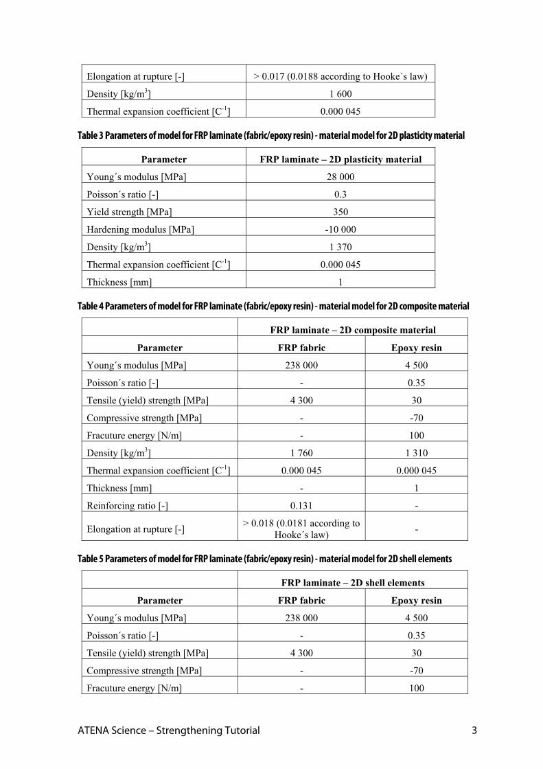
3. MODEL DESCRIPTION Strengthening of reinforced concrete beam without smeared reinforcement is analyzed in this tutorial. The geometrical and material properties of the beam correspond to the experimental setup by Leonhard in 1962, see Figure 2. More details about the problem or experiment can be also obtained from the original report [11] or from the program developer or distributor. The problem is symmetric around its vertical axis; therefore, only one symmetric half of the beam is utilized in the model.
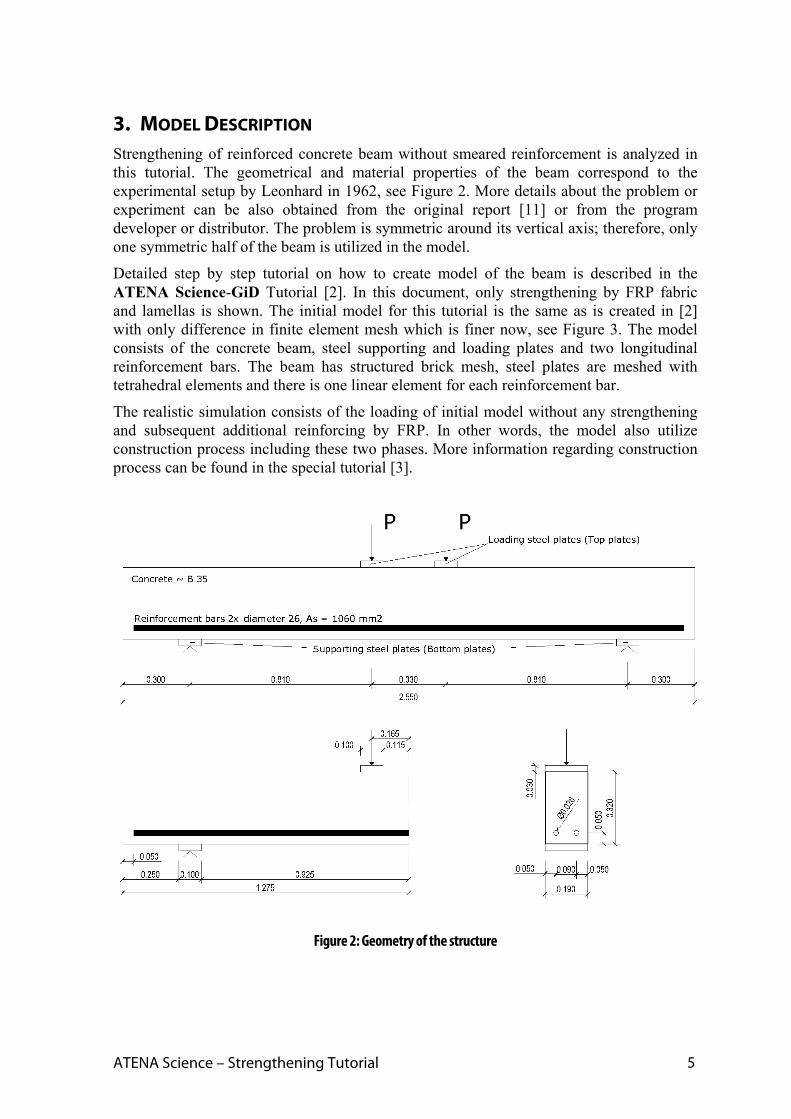
Detailed step by step tutorial on how to create model of the beam is described in the ATENA Science-GiD Tutorial [2]. In this document, only strengthening by FRP fabric and lamellas is shown. The initial model for this tutorial is the same as is created in [2] with only difference in finite element mesh which is finer now, see Figure 3. The model consists of the concrete beam, steel supporting and loading plates and two longitudinal reinforcement bars. The beam has structured brick mesh, steel plates are meshed with tetrahedral elements and there is one linear element for each reinforcement bar.
The realistic simulation consists of the loading of initial model without any strengthening and subsequent additional reinforcing by FRP. In other words, the model also utilize construction process including these two phases. More information regarding construction process can be found in the special tutorial [3].
Figure 2: Geometry of the structure
6
Figure 3: Model of symmetric half of the beam
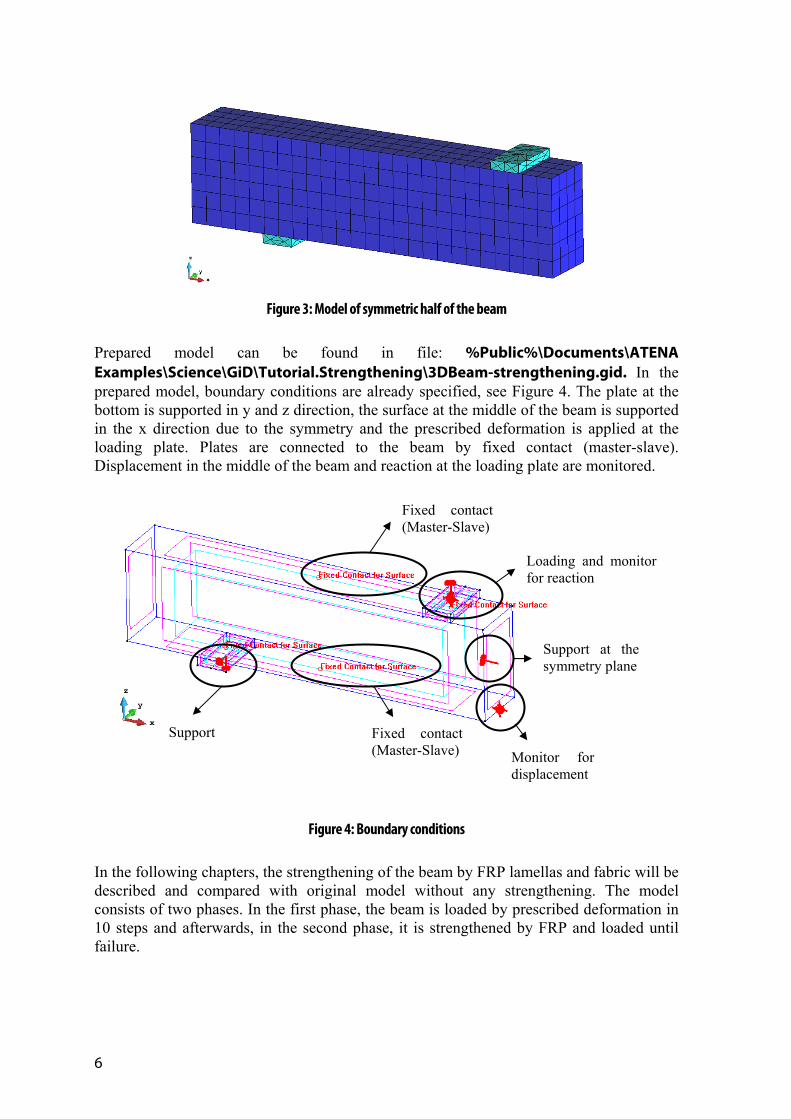
Prepared model can be found in file: %Public%\Documents\ATENA Examples\Science\GiD\Tutorial.Strengthening\3DBeam-strengthening.gid. In the prepared model, boundary conditions are already specified, see Figure 4. The plate at the bottom is supported in y and z direction, the surface at the middle of the beam is supported in the x direction due to the symmetry and the prescribed deformation is applied at the loading plate. Plates are connected to the beam by fixed contact (master-slave). Displacement in the middle of the beam and reaction at the loading plate are monitored.
Figure 4: Boundary conditions
In the following chapters, the strengthening of the beam by FRP lamellas and fabric will be described and compared with original model without any strengthening. The model consists of two phases. In the first phase, the beam is loaded by prescribed deformation in 10 steps and afterwards, in the second phase, it is strengthened by FRP and loaded until failure.
Monitor for displacement
Fixed contact (Master-Slave)
Loading and monitor for reaction
Support at the symmetry plane
Support
Fixed contact (Master-Slave)
ATENA Science – Strengthening Tutorial 7
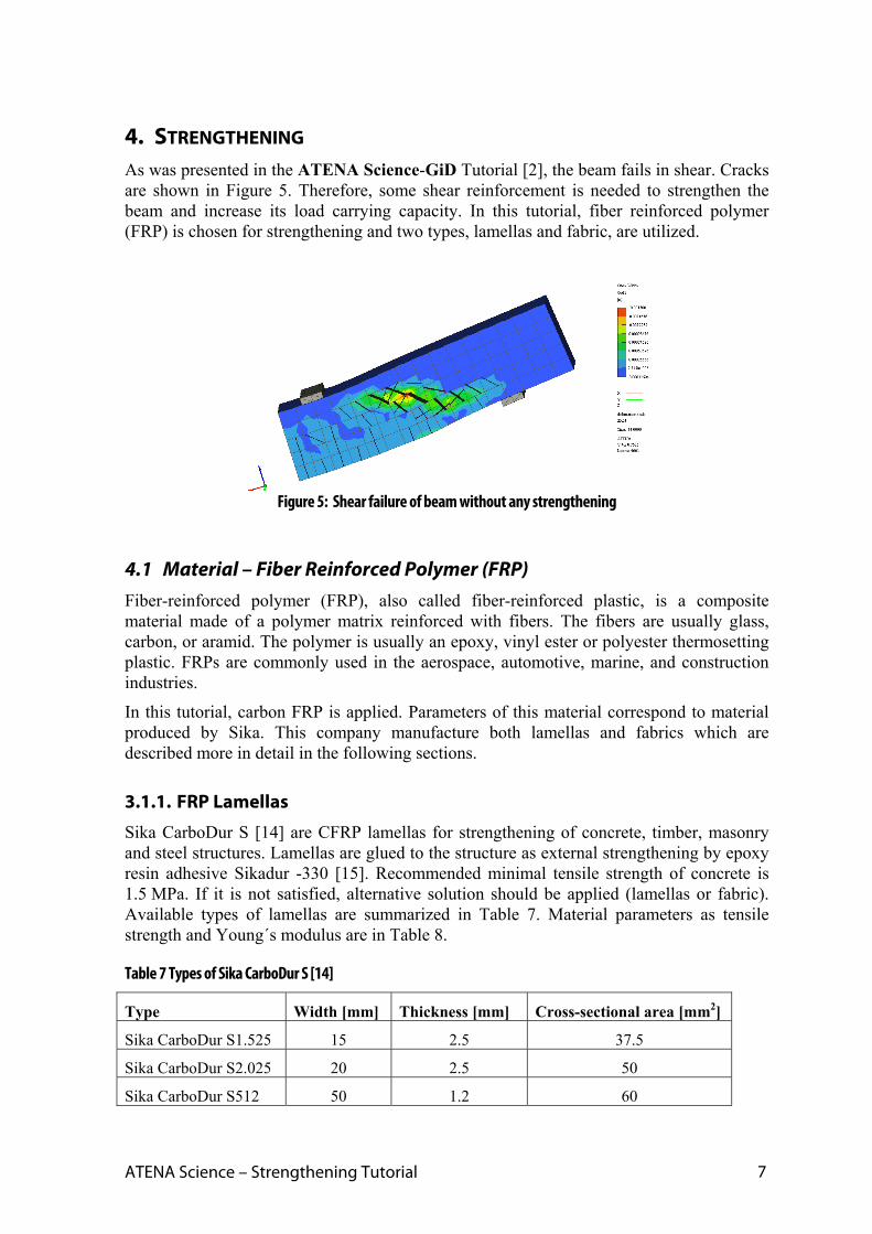
4. STRENGTHENING As was presented in the ATENA Science-GiD Tutorial [2], the beam fails in shear. Cracks are shown in Figure 5. Therefore, some shear reinforcement is needed to strengthen the beam and increase its load carrying capacity. In this tutorial, fiber reinforced polymer (FRP) is chosen for strengthening and two types, lamellas and fabric, are utilized.
Figure 5: Shear failure of beam without any strengthening
4.1 Material – Fiber Reinforced Polymer (FRP) Fiber-reinforced polymer (FRP), also called fiber-reinforced plastic, is a composite material made of a polymer matrix reinforced with fibers. The fibers are usually glass, carbon, or aramid. The polymer is usually an epoxy, vinyl ester or polyester thermosetting plastic. FRPs are commonly used in the aerospace, automotive, marine, and construction industries.
In this tutorial, carbon FRP is applied. Parameters of this material correspond to material produced by Sika. This company manufacture both lamellas and fabrics which are described more in detail in the following sections.
3.1.1. FRP Lamellas
Sika CarboDur S [14] are CFRP lamellas for strengthening of concrete, timber, masonry and steel structures. Lamellas are glued to the structure as external strengthening by epoxy resin adhesive Sikadur -330 [15]. Recommended minimal tensile strength of concrete is 1.5 MPa. If it is not satisfied, alternative solution should be applied (lamellas or fabric). Available types of lamellas are summarized in Table 7. Material parameters as tensile strength and Young´s modulus are in Table 8.
Table 7 Types of Sika CarboDur S [14]
Type Width [mm] Thickness [mm] Cross-sectional area [mm2]
Sika CarboDur S1.525 15 2.5 37.5
Sika CarboDur S2.025 20 2.5 50
Sika CarboDur S512 50 1.2 60

8
Sika CarboDur S613 60 1.3 78
Sika CarboDur S614 60 1.4 84
Sika CarboDur S812 80 1.2 96
Sika CarboDur S814 80 1.4 112
Sika CarboDur S912 90 1.2 108
Sika CarboDur S914 90 1.4 126
Sika CarboDur S1012 100 1.2 120
Sika CarboDur S1014 100 1.4 140
Sika CarboDur S1212 120 1.3 156
Sika CarboDur S1214 120 1.4 168
Sika CarboDur S1512 150 1.2 180
Table 8 Material parameters of Sika CarboDur S [14]
Material parameter Mean value
Young´s modulus [MPa] 165 000
Tensile strength [MPa] 3 100
Strain at fracture – min. value [-] 0.017
Density [kg/m3] 1 600
3.1.2. FRP Fabric
The second material used in this tutorial for strengthening of concrete beam is SikaWrap -230 C/45. It is fabric made of carbon fibers. Sikadur -330 is applied as an impregnation resin. At first, resin is applied to the prepared substrate using a trowel, roller or brush. Afterwards, SikaWrap fabric is placed in the required direction onto the Sikadur -330. The fabric should be carefully worked into the resin until the resin is squeezed out between and through the fiber strands and distributed evenly over the whole fabric surface. Material parameters of the dry fabric and laminate (fabric and resin together) are summarized in Table 9.
Table 9 Material parameters of SikaWrap -230 C/45 [16]
Material parameter Mean value
Young´s modulus of dry fabric [MPa] 238 000
Tensile strength of dry fabric [MPa] 4 300
Strain at fracture of dry fabric [-] 0.018
Thickness of dry fabric [mm] 0.131
Fabric density [g/cm3] 1.76
Young´s modulus of laminate [MPa] 28 000
Load for layer of laminate [kN/m] 350
Thickness of laminate [mm] 1.0

ATENA Science – Strengthening Tutorial 9
3.1.3. Epoxy Impregnation Resin
Epoxy impregnation resin Sikadur -330 is used for application of SikaWrap. For the model in ATENA, it is necessary to know also its parameters, they are summarized in Table 10.
Table 10 Material parameters of Sikadur -330 [15]
Material parameter Mean value
Young´s modulus [MPa] 3800
Tensile strength [MPa] 30
Strain at fracture [-] 0.009

10
5. STRENGTHENING BY FRP LAMELLAS This chapter contains a step by step explanation how to define strengthening by FRP lamellas in the model created in ATENA-GiD software.
Model is prepared in the file: %Public%\Documents\ATENA Examples\Science\GiD\Tutorial.Strengthening\3DBeam-strengthening.gid that can be opened by selecting Files | Open in GiD. User must have installed programs GiD and ATENA to start nonlinear analysis using the ATENA-GiD system. If you do not have installed the above mentioned programs yet, you can install them following the instructions from the ATENA-GiD manual [4].
At first, user has to decide location of FRP lamellas and then define their geometry in GiD. As lamellas are more line strengthening elements than planar, they are modelled as 1D reinforcement elements. Afterwards, material corresponding to FRP must be created, assigned to the lamellas and finally the time when lamellas are activated should be determined. Lamellas activation is defined in the material model.
5.1 Geometry of FRP Lamellas Due to the shear failure of beam, see Figure 5, strengthening should be applied in the vertical direction in the area between top loading plate and bottom supporting plate to supply missing stirrups. As the FRP lamellas are modelled as a reinforcement bars, it is sufficient to define just lines in the location where we want to use these lamellas. Three vertical FRP lamellas are used on the each side of the beam, see Figure 6.
Figure 6: Dimensions of FRP lamellas
At first, one point defining the reinforcement line must be entered to the model. It is possible to do it by coordinates of the point. Click on Geometry/Create/Point and put coordinated of the first point into the command line. We insert point marked at the Figure 6 and its coordinates are [0.505; 0.005; 0.0025]. In spite of fact that FRP lamellas are glued at the surface of the beam, they must be inside the beam in the model due to the connection between lamellas (modelled as a reinforcement bar) and concrete volume finite elements.
[0.505; 0.005; 0.0025]

ATENA Science – Strengthening Tutorial 11
Figure 7: Definition of the point
Afterwards, the rest of geometry can be defined just by copying the first point according to the dimensions in Figure 6 and there is no need to insert other points. When the definition of the first point is completed, it can be translated vertically by 0.315 m together with extrusion to the line, see Figure 8.
Figure 8: Creation of the first FRP lamella by extruding point to line
Created line is then copied in the y-direction by 0.18 m without any extrusion, see Figure 9. Finally, two created lines are copied in the x-direction by 0.2 m and multiple copy

12
should be set to 2, see Figure 10. Model after definition of the lamellas geometry is shown in Figure 11.
Figure 9: Copying of the line in y-direction by 0.18 m
Figure 10: Creating the rest of lines

ATENA Science – Strengthening Tutorial 13
Figure 11: Model with FRP lamellas
5.2 Material Model for FRP Lamellas Material model is created according to the parameters of FRP lamellas Sika CarboDur S
summarized in Table 8. User has to choose material for 1D reinforcement and define new one that can be called Sika CarboDur S812 because this type is chosen from Table 7.
Young´s modulus, area, yield strength, failure parameters and density are based on values from the chapter 3.1.1. Connection between beam and FRP lamellas is modelled by bond with none fixed end. Default values for bond strength and function for bond slip are used. Bar perimeter corresponds to CarboDur S812 [14].
Material parameters of FRP lamellas are summarized in the Figure 12 to Figure 16.
After definition of material model, this model should be assigned to six FRP lamellas created in the previous chapter by selecting Assign/Lines in the material model definition.

14
Figure 12: Material model of Sika CarboDur S812- basic parameters
Figure 13: Material model of Sika CarboDur S812- reinforcement function

ATENA Science – Strengthening Tutorial 15
Figure 14: Material model of Sika CarboDur S812- miscellaneous
Figure 15: Material model of Sika CarboDur S812- element geometry

16
Figure 16: Material model of Sika CarboDur S812- bond parameters
5.3 Lamellas Activation
In the prepared model, there are two intervals, user can find them by clicking on icon . The first interval is multiplied 10 times and contains 10 steps. The second interval is multiplied by 200 and contains 50 steps. Calculation is divided into two parts due to the strengthening. According to the real structures, where strengthening is applied to the surface after some service time when structure struggles with problems, there is just concrete beam with two longitudinal reinforcement bars in the first interval which is in the second interval strengthened by FRP lamellas.
Application of FRP lamellas in the interval no. 2 can be defined in the material model. On the tab Element geometry, there is parameter called ‘Application from Interval’ where user can choose from which interval the reinforcement will be applied. In this case, user has to insert interval no. 2, see Figure 17.

ATENA Science – Strengthening Tutorial 17
Figure 17: Definition of activation of FRP lamellas in the interval no. 2
5.4 Calculation After the definition of the FRP lamellas, user must regenerate finite element mesh to assign material described in the previous subsection to the mesh. It should be done by Mesh | Generate mesh. For the FRP lamellas, one finite element per one lamella is sufficient. It can be set by Mesh | Structured | Lines | Assign number of cells. The number of cells should be 1 and it must be assigned to FRP lamellas. After generation, the tab with mesh information appears and it is possible to control number of finite elements in this tab, see Figure 18. There are 8 linear elements that correspond to reinforcement bars. This number is right because we have two longitudinal bars and six FRP lamellas in the model.
Figure 18: Mesh information

18
Finally, the model is ready to start calculation by pressing button .
Final model can be found in the file: %Public%\Documents\ATENA Examples\Science\GiD\Tutorial.Strengthening\ 3DBeam-strengthening-A-6 lamellas.gid.
Figure 19: Running calculation
5.5 Results When the calculation is complete, load-displacement diagram can be compared with the model without any strengthening. Procedure how to obtain load-displacement diagram from calculation in ATENA Studio is described in the basic tutorial [2]. Comparison of diagrams is shown in Figure 20. Strengthening by 6 FRP bars increases load-bearing capacity by 5.8 %. Failure of the beam is not brittle as in previous calculation, ductility of the beam is higher now.
Failure of the unstrengthened model is due to the shear diagonal crack, see Figure 21 (left). Failure of the model with FRP bars is also caused by shear but two diagonal cracks are formed here in the areas between FRP lamellas, see Figure 21 (right). The width of the cracks in the strengthened model is half compared with the original model.
As increase of the load-bearing capacity is not so high in this case, the beam should be strengthened by more FRP lamellas or lamellas with higher cross-sectional area. As an example, results of the beam strengthened by 8 FRP bars (distance between each other is 150 mm) are added to the diagram in Figure 22. Capacity increases now by 13.7 %.
Presented results are in chapter 7 compared with other types of strengthening.

ATENA Science – Strengthening Tutorial 19
0
20
40
60
80
100
0 2 4 6 8 10
Reaction [kN
]
Deflection [mm]
Withoutstrengthening
Strengtheningby FRP bars
Figure 20: Load-displacement diagrams
Figure 21: (left) Failure of unstrengthened beam; (right) failure of beam strengthened by 6 FRP lamellas
0
20
40
60
80
100
0 2 4 6 8 10
Reaction [kN
]
Deflection [mm]
Withoutstrengthening
Strengtheningby 6 FRP bars
Strengtheningby 8 FRP bars
Figure 22: Comparison of results of beam with no FRP lamellas, 6 and 8 FRP lamellas

20
6. STRENGTHENING BY FRP FABRIC This chapter contains a step by step explanation how to define strengthening by FRP fabric in the model created in ATENA-GiD software.
Model is prepared in the file: %Public%\Documents\ATENA Examples\Science\GiD\Tutorial.Strengthening\3DBeam-strengthening.gid.
The basic process is the same as for FRP lamellas. At first, user has to decide location of FRP fabric and then define their geometry in GiD. Afterwards, material corresponding to FRP must be created, assigned to the fabric and finally the time when fabric is activated should be determined. The difference is between activation of FRP lamellas and fabric. Unlike the lamellas, fabric are activated in the interval definition, not in the material model.
One of the most important things that user should learn during these tutorial is how to create contact (interface) elements between two parts of the structure with non-compatible mesh. As we need to connect the FRP fabric with the beam somehow, issue with interface elements occurs here and it is described in the chapter 6.1.
6.1 Geometry of FRP Fabric FRP fabric can be cut with special scissors or razor knife to any dimension. For our model, the fabric is used in U-shape to wrap critical section of the beam. Position of the FRP fabric is shown in Figure 23. The fabric is modelled as 2D surface. As the first point, [0.405; 0; 0] can be entered. Afterwards, it is necessary to make a line as for the FRP lamellas in the previous chapter. Finally, surface is created by command Copy and choosing line with the extrusion to the surface. One surface is in the vertical direction and second in the horizontal direction. The third part of the U-cross section is created again by copying.
Figure 23: Position of FRP fabric
At this stage, geometry of the FRP fabric is already finished. Now, it is necessary to model epoxy resin, connection between fabric and beam. It is done by interface elements. Surfaces of the beam and FRP fabric do not have the same geometry, so finite element mesh is not compatible. In this case, user has to create one auxiliary surface that serves to create the interface and also to connect interface with the beam. In our model, we can copy the surface of the FRP fabric with zero distance, see Figure 25, to obtain two same
0.6 m0.105 m
0.105 m
[0.405; 0; 0]

ATENA Science – Strengthening Tutorial 21
surfaces. To distinguish these surfaces, it is useful to create special layer and call it e.g. “Wrap Interface”, see Figure 24. Before duplication of FRP fabric surface, this new layer is chosen and after the copying, new surfaces are automatically assign to the layer “Wrap Interface”. Afterwards, it is easy to distinguish between FRP surface and auxiliary surface for interface.
Figure 24: Layers in the model
Figure 25: Settings for copying of surfaces – layer “Wrap Interface” is activated, dimension for copying is 0 m
Before creation of special element for interface, principle of this method is explained. Interface element can be created at the area with the compatible mesh. It is the reason why we duplicate surface of FRP fabric. Afterwards, duplicated surface of FRP is connected by Master-Slave fixed contact to the beam to obtain surface with compatible mesh on the beam. Finally, the interface element is created between the surfaces of FRP fabric and duplicated one. The interface is in fact volume with zero thickness. Described principle is shown in the Figure 27.

22
Figure 26: Principle of interface in the area with incompatible mesh
If the mesh is compatible between two surfaces (surfaces has the same geometry), interface element can be created by selecting Geometry | Create | Contact | Volume. If layer “Wrap Interface” is active at this time, the interface volume is created in this layer after choosing two duplicated surfaces (surface of the FRP fabric and auxiliary surface in the layer “Wrap Interface”). User has to create interface gradually for each pair of surfaces, it does not work when all six surfaces are chosen together.
Finally, Master-Slave condition must be assigned between auxiliary surface and beam
surface. Is can be done by clicking icon for conditions and choosing Fixed Contact for Surface, see Figure 27. Master is the surface with coarser mesh (beam surface) and slave corresponds to finer mesh (auxiliary surface in the layer “Wrap Interface”), see Figure 28. Contact at the side of the beam can be called “Contact” but it is necessary to be careful with the contact at the bottom of the beam because there is already contact between beam and supporting plate, see Figure 28. Therefore, slave contact at the bottom auxiliary surface must be called also “Bottom” in accordance with the master contact.
FRP fabric Auxiliary surface Concrete beam
Interface volume is created between FRP fabric and
auxiliary surface
Fixed contact is created between concrete beam and auxiliary surface

ATENA Science – Strengthening Tutorial 23
Figure 27: Definition of Master-Slave contact
Figure 28: Fixed (Master-Slave) contacts in the model
6.2 Modeling of FRP Fabric Material model is created according to the parameters of FRP fabric SikaWrap -230 C/45 summarized in Table 9. To compare different approaches how to model strengthening by wraps, different types of material models are utilized. In this tutorial, four ways how to model strengthening by FRP fabric are presented:
2D membrane elements with plasticity material,
2D membrane elements with composite material,

24
2D shell elements,
3D shell elements.
All material models represent laminate, i.e. FRP fabric together with epoxy resin. Those material models are connected with the beam by interface elements.
The first material model for steel contains just one “layer” where are properties of FRP and epoxy resin mixed together. It is advantage of this model because user does not have to search for parameters of epoxy resin that are usually hard to find. Disadvantage of this model is that it cannot capture orthotropic behavior as it is introduced in other three models. Behavior of the material model is the same for all directions which is not true in the case of SikaWrap -230 C/45 that has fibers only in one direction. On the contrary, the definition of the other three models is little bit more difficult (due to the epoxy resin and overall larger number of parameters) but the orthotropic behavior is considered there by smeared reinforcement that can be defined just in one direction (e.g. FRP fibers in this case). Detailed description of each model can be found in the following chapters.
6.2.1. 2D Membrane Elements with Plasticity Material
In this approach the FRP laminate is modeled using the Von Mises plasticity model. Von Mises yield criterion says that the yielding of materials begins when the second invariant of stress deviator tensor J2 reaches a critical value [1]. This theory is applicable best to ductile materials, such as metals. Prior to yield, material response is assumed to be elastic.
In the model, the definition of Von Mises Steel consists of basic parameters such as Young´s modulus, Poisson´s ratio, yield strength, hardening modulus and miscellaneous parameters as density and thermal expansion coefficient, see Figure 29 and Figure 30. Values correspond to the laminate parameters summarized in Table 9. Hardening modulus is negative because we do expect softening after reaching yield strength. Poisson´s ratio is 0.3 which should be optimal for epoxy resin/FRP fiber laminate according to the [8].
In the tab with element geometry (Figure 31), it is necessary to specify plane stress idealization because we model fabric as 2D elements. Thickness should correspond to the thickness of laminate and it is 1 mm according to material list of SikaWrap -230 C/45.
Figure 29: Von Mises plasticity model of laminate – basic parameters

ATENA Science – Strengthening Tutorial 25
Figure 30: Von Mises plasticity model of laminate – miscellaneous parameters
Figure 31: Von Mises plasticity model of laminate – element geometry
Together with definition of the real SikaWrap material model, the soft version that is used in the calculation before gluing of fabric to the beam must be defined. It can be called SikaWrap Soft and all the parameters except Young´s modulus remain the same. Young´s modulus is divided by 10000 to not contribute to the beam stiffness, see Figure 32.

26
Figure 32: Von Mises plasticity model of soft laminate – basic parameters
Finally, material “SikaWrap Soft” is assigned to the surface belonging to FRP fabric. The definition of construction process where soft material is replaced by FRP is described in the chapter 6.4.
6.2.2. 2D Membrane Elements with Composite Material
The second option uses membrane elements with a composite material, which is normally used to simulate brittle materials such as concrete with internal smeared reinforcement. This material name is Reinforced Concrete material model and it allows to combine a brittle material with internal reinforcement. This is exactly the situation in the FRP laminate, which consists of a brittle epoxy raisin and a carbon fiber reinforcing net. Reinforcement is considered as smeared, it is not necessary to put its exact position to the model and only average effect of reinforcement is taken into account. For the purpose of strengthening, concrete part of the model serves as epoxy resin (matrix) and FRP is modeled as a smeared reinforcement. By smeared reinforcement specified only in one direction, orthotropy is included in the model and its behavior should better correspond to the real FRP then isotropic model for 2D plasticity material.
On the contrary to the previous model for 2D plasticity material, this model requires more parameters as an input, mainly for epoxy resin:
Parameters of epoxy resin (concrete matrix):
Young´s modulus, Poisson´s ratio, Tensile strength, Compressive strength, Fracture energy, Compressive plastic strain, Critical compressive displacement, etc.
Parameters of FRP (reinforcement):
Young´s modulus, Reinforcing ratio, Direction of reinforcement, Yield strength
Some properties of epoxy resin can be found in the product data sheet of Sikadur -330 [15] and some other in literature, e.g. compressive strength in [13] and fracture energy in [9]. Other parameters that are hard to find are used in their default values.
New material should be created by using menu item Data | Materials | Solid Concrete and selecting Reinforced Concrete. New material that is used for FRP fabric is created by
pressing the button . Name of the material is “SikaWrap -230 C/45” according to the
ATENA Science – Strengthening Tutorial 27
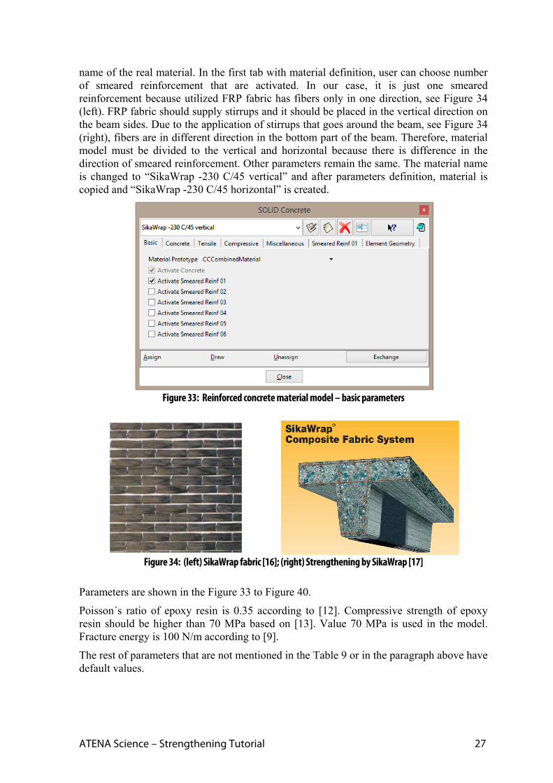
name of the real material. In the first tab with material definition, user can choose number of smeared reinforcement that are activated. In our case, it is just one smeared reinforcement because utilized FRP fabric has fibers only in one direction, see Figure 34 (left). FRP fabric should supply stirrups and it should be placed in the vertical direction on the beam sides. Due to the application of stirrups that goes around the beam, see Figure 34 (right), fibers are in different direction in the bottom part of the beam. Therefore, material model must be divided to the vertical and horizontal because there is difference in the direction of smeared reinforcement. Other parameters remain the same. The material name is changed to “SikaWrap -230 C/45 vertical” and after parameters definition, material is copied and “SikaWrap -230 C/45 horizontal” is created.
Figure 33: Reinforced concrete material model – basic parameters
Figure 34: (left) SikaWrap fabric [16]; (right) Strengthening by SikaWrap [17]
Parameters are shown in the Figure 33 to Figure 40.
Poisson´s ratio of epoxy resin is 0.35 according to [12]. Compressive strength of epoxy resin should be higher than 70 MPa based on [13]. Value 70 MPa is used in the model. Fracture energy is 100 N/m according to [9].
The rest of parameters that are not mentioned in the Table 9 or in the paragraph above have default values.
28
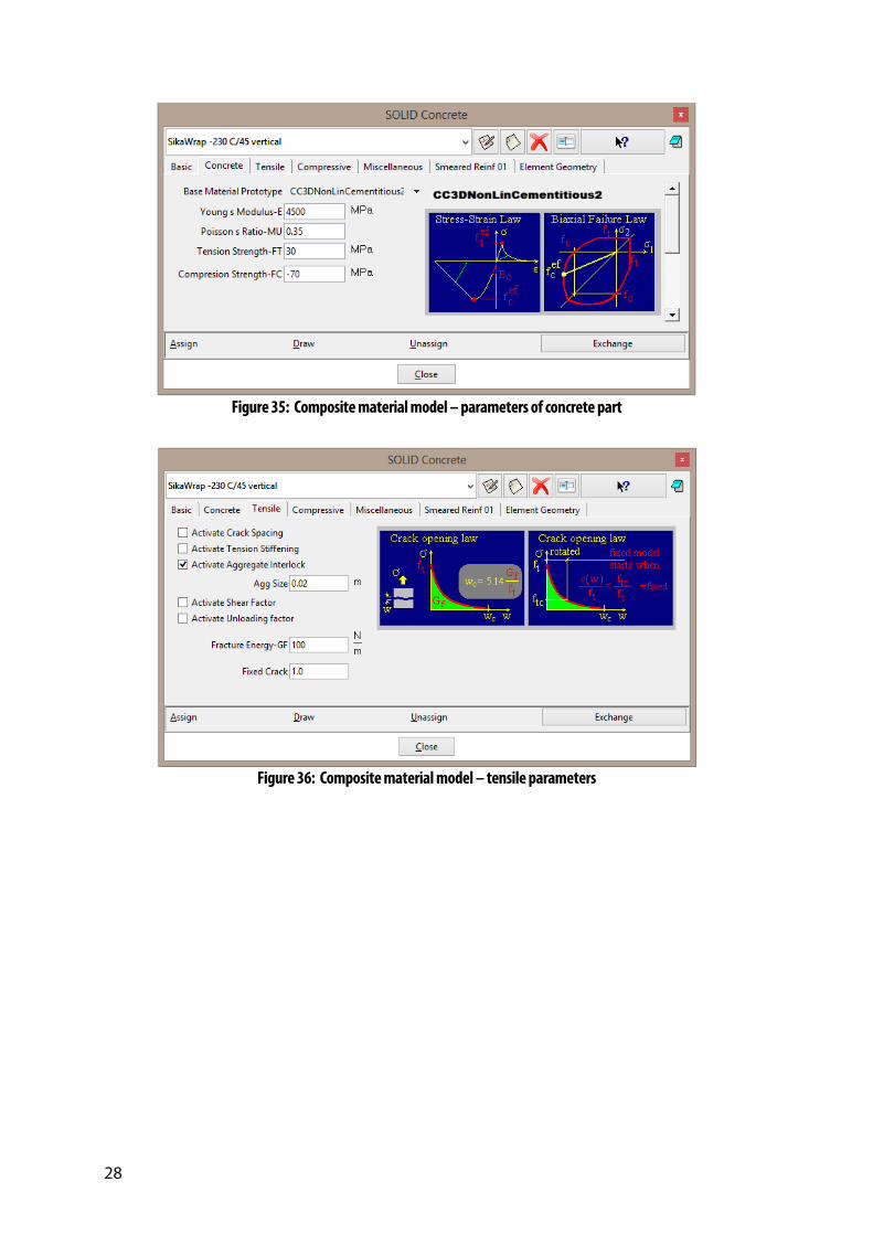
Figure 35: Composite material model – parameters of concrete part
Figure 36: Composite material model – tensile parameters

ATENA Science – Strengthening Tutorial 29
Figure 37: Composite material model – compressive parameters
Figure 38: Composite material model – miscellaneous parameters
Parameters of reinforcement, i.e. FRP fibers, are in Figure 39. For strengthening in the vertical direction at the side of the beam, fibers orientation should be in global z-axis. However, fabric is modelled only as 2D element that has x-y coordinate system. The orientation of system is defined in the tab Element Geometry, see Figure 40, and the x-axis of 2D material is identical with global x-axis. Therefore, the global z-axis corresponds to the y-axis of fabric and the unit vector defining direction of the fibers is then (0; 1; 0). The same vector is used for the definition of fibers at the bottom of the beam because fibers go in the y-axis direction again.
Reinforcing ratio means cross-sectional area ratio with respect to the base material. In our case, base material is epoxy resin with thickness 1 mm and FRP fibers are reinforcement with thickness 0.131 mm. Ratio is calculated by division of these two values and it is 0.131.

30
Figure 39: Composite material model – parameters of smeared reinforcement
For 2D element geometry that is specified in tab Element Geometry, see Figure 40, it is useful to define the local x-axis direction by vector to know exactly the local system. In our case, local x-axis is the same with the global x-axis, so the vector is (1; 0; 0).
Figure 40: Composite material model – element geometry
In the same way as for the previous material, soft material must be assigned to the surface before FRP application. To avoid any nonlinearities, elastic material is utilized. Two elastic models are defined, first one for vertical part of FRP and second for horizontal.
Direction of smeared reinforcement

ATENA Science – Strengthening Tutorial 31
Both models have the same parameters, they differ only in name. The name cannot be the same because we need to change one material for the “SikaWrap -230 C/45 vertical” and second for “SikaWrap -230 C/45 horizontal.” Young´s modulus is 10000 times lower than laminate modulus, i.e. 2.8 MPa.
Figure 41: Elastic material model for soft material – basic parameters
Finally, material “SikaWrap elastic vertical/horizontal” is assigned to the vertical/horizontal surface belonging to FRP fabric.
To conclude this chapter, parameters of carbon fibers, epoxy resin and laminate are compared in the Table 11. For parameters that are found in literature, reference number is given, parameters without reference are taken from product data sheet. Base material model for SikaWrap corresponds to epoxy resin and smeared reinforcement to carbon fibers. Parameters of laminate were utilized in the chapter 1 for model of 2D steel.
Table 11 Material parameters of SikaWrap
Parameter Carbon fibers Epoxy resin Laminate
Young´s modulus [MPa] 238000 4500 28000
Poisson´s ratio [-] 0.2 0.35 [12] 0.3 [8]
Tensile strength [MPa] 4300 30 350
Compressive strength [MPa] - -70 [13] -
Fracuture energy [N/m] - 100 [9] -
Density [kg/m3] 1760 1310 1370
Thermal expansion coefficient [C-1] 0.000045 0.000045 0.000045
Thickness [mm] 0.131 1 1
Elongation at rupture [-] 0.018 - -

32
6.2.3. 2D Shell Elements
This approach is very similar to the method described in Section 6.2.2, but the laminate is modeled by 2D shell elements, which enables the consideration of the laminate bending stiffness. The epoxy resin is modeled by the fracture-plastic material CC3DNonLinCementitious2 (concrete material) as the basic shell material and the carbon fibers are included as special reinforcement layers. The orthotropic nature of the laminate can be considered in this approach.
Basic geometry is the same as for 2D reinforced concrete, only material parameters differ as it will be shown in this chapter. Another difference is in finite element mesh that needs to be quadratic for shell elements. Therefore, the quadratic mesh is set for the whole model by Mesh | Quadratic type | Quadratic. Linear mesh is then assigned back to the non-quadratic parts (beam and plates) in the material model definition. In the tab Element Geometry, option for Non-quadratic Element must be selected, see Figure 42.
Figure 42: Definition of non-quadratic element
Preparation of shell material model starts by clicking icon and consists of base material model that is afterwards used in the layers together with smeared reinforcement. The material model has two modifications, for horizontal and vertical direction. New
material model is created by icon and the name can be “SikaWrap 2Dshell horizontal”. One smeared reinforcement is activated in the first tab, see Figure 43.
Figure 43: Material model for 2D shell elements - basic parameters

ATENA Science – Strengthening Tutorial 33
The second tab is dedicated to the definition of local coordinate system. For the shell element, the local axis z must correspond to the shell normal direction and other two axis lie in the shell plane. In the case of horizontal FRP fabric, the local axis z is identical with the global z-axis. The direction of local x-axis is defined in the accordance with the global x-axis. Definition is made by unit vectors shown in Figure 44.
Figure 44: Material model for 2D shell elements – local coordinate system
The third tab defines number of layers, reference thickness and base material for shell element, see Figure 45. Recommended number of layers is 4 and it is also utilized in this model. FRP laminate has uniform thickness 1 mm and “SikaWrap Base” is used as a base material. Base material corresponds to the model for concrete (3D NonlinearCementitious 2) and its parameters are given in Table 11 in column “Epoxy resin”.
Figure 45: Material model for 2D shell elements – parameters of base
Input of FRP (reinforcement) parameters is shown in Figure 46. As a contrary to the reinforcement definition in reinforced concrete model, it is necessary to specify location and distance from the surface while other parameters are the same. The location of the reinforcement is important for example for slabs where we need to differ between

34
reinforcement at the top and bottom surface. In this model, reinforcement is in the middle of the epoxy resin, so the location can be either top or bottom and the distance is 0.5 mm which is in the middle of 1 mm-thick epoxy resin.
The last tab contains element geometry, and element type is specified here. For 2D approximation of FRP fabric, element CCIsoShellQuad is utilized and the thickness is 1 mm, see Figure 47.
Figure 46: Material model for 2D shell elements – parameters of reinforcement
ATENA Science – Strengthening Tutorial 35
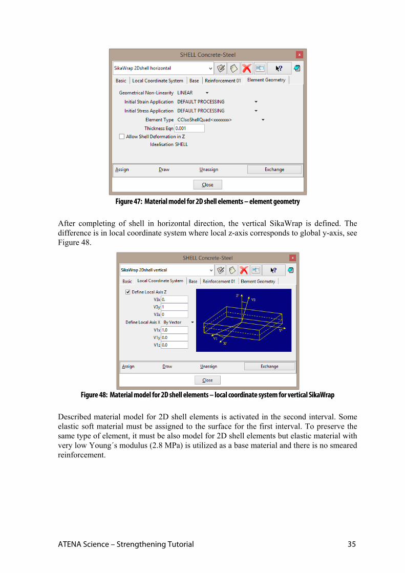
Figure 47: Material model for 2D shell elements – element geometry
After completing of shell in horizontal direction, the vertical SikaWrap is defined. The difference is in local coordinate system where local z-axis corresponds to global y-axis, see Figure 48.
Figure 48: Material model for 2D shell elements – local coordinate system for vertical SikaWrap
Described material model for 2D shell elements is activated in the second interval. Some elastic soft material must be assigned to the surface for the first interval. To preserve the same type of element, it must be also model for 2D shell elements but elastic material with very low Young´s modulus (2.8 MPa) is utilized as a base material and there is no smeared reinforcement.

36
Figure 49: Material model for soft 2D shell elements – parameters of base
6.2.4. 3D Shell Elements
The last option how to model strengthening by FRP fabric are 3D shell elements. Parameters of the material model are the same as for 2D shell, only geometry in the last tab is modified. Instead of 2D element type CCIsoShellQuad 3D elements CCIsoShellBrick are utilized, see Figure 50.
Figure 50: Material model for 3D shell elements – element geometry
Because FRP fabric is modeled in this case by 3D elements, geometry of the FRP must be modified. In all three cases, 2D elements were utilized and fabric was modeled only as surface. Now, it must be changed to volume. The easiest way, how to do it, is to copy surfaces by 1 mm in the normal direction to their planes and extrude them to volumes. But this procedure do not connect surfaces at the edges of FRP fabric, see Figure 51. For this reason, the points at the edges are shifted according to Figure 52 and surfaces at these edges are collapsed to create perfect connection between volumes.
Soft elastic material with modulus 2.8 MPa

ATENA Science – Strengthening Tutorial 37
Figure 51: 3D shell – detail of contact between vertical and horizontal part of FRP fabric
Figure 52: 3D shell – modification of area around contact between vertical and horizontal FRP fabric
Other settings of this model are the same as for 2D shell elements. Both variation – vertical and horizontal – material for 3D shell elements must be prepared. Before activation of FRP fabric in the second interval, material for 3D shell elements with soft base material (low Young´s modulus 2.8 MPa) must be assigned to the volumes.
6.2.5. Material Model for Interface
Last material model that must be specified is interface. In this case, interface represents contact between epoxy resin reinforced by FRP fibers and concrete beam. Setting of interface parameters is described in the ATENA Troubleshooting [5]. The interface material is based on Mohr-Coulomb criterion with tension cut off. Parameters as tensile strength, shear cohesion and friction describe real physical properties. Other parameters regarding stiffness serve for numerical purposes.
As parameters of interface are usually not known, estimated values are used as a first approach. Friction coefficient between 0.3 and 0.5 is not far from reality. Therefore, 0.3 is applied in this model. Tensile strength is set to be similar with beam tensile strength. i.e. 3 MPa. Cohesion is recommended to be set to 1-2 times higher than interface tensile strength, i.e. 6 MPa in this model.
Normal and tangential stiffness can be based on the stiffness of the adjacent finite elements. Stiffness can be estimated using following formula [1]

38
K = E / (element size)*10, (1)
where E is elastic modulus of surrounding material and element size is size of the surrounding finite elements. In our case, size of the elements in the beam is 0.05 m and Young´s modulus of concrete is 32000 MPa. Using formula (1), interface stiffness is 6400000 MN/m3. The residual stiffness values are recommended about 1/100 – 1/1000 of the initial values.
Interface properties are shown in Figure 53 and Figure 54.
Figure 53: Basic parameters of interface

ATENA Science – Strengthening Tutorial 39
Figure 54: Miscellaneous parameters of interface
6.3 Finite Element Mesh Before starting calculation, finite element mesh must be assigned to FRP fabric. Except model with 3D shell elements, all models will have quadrilateral 2D elements instead of triangle that are default option. Element type has to be changed by Mesh | Element type | Quadrilateral and choosing surfaces belonging to FRP fabric. In the model with 3D fabric, default tetrahedras are changed to hexahedras by menu item Mesh | Element type | Hexahedra and choosing appropriate volume.
Afterwards, size of finite element mesh must be set up. Structured mesh for each surface (volumes in case of 3D shell elements) is chosen and size is assigned as a number of elements at each line. Mesh should be finer than beam mesh due to the few reasons. One of them is connection between fabric and beam that is realized by master-slave contact. It is recommended to create finer mesh at the slave part (i.e. FRP fabric) to provide good connection between master and slave. The second reason is to capture eventual delamination and tearing FRP fabric away from concrete beam by finer mesh. The third reason is related to graphics, i.e. to better distinguish between beam and FRP fabric during calculation and post-processing by difference in mesh size.
Based on described requirements, mesh with size shown in Figure 55 is used in the models. Mesh of 3D shell elements is the same and it has one element per thickness of FRP fabric.
Finally, mesh is generated by Mesh | Generate mesh.
Figure 55: Number of elements at each line of FRP fabric
6.4 Fabric Activation In the same way as for the lamellas, fabric is applied to the structure in the second interval. The difference is in type of activation in the model. For the models presented in chapter 6, application is defined by exchange of materials during the interval specification. User has to prepare material model for FRP fabric and model for soft material that is used for the

40
elements before they are glued to the beam. Elements for FRP fabric are in the model throughout whole calculation. At the time they are glued, only the material properties change. Before application, these elements have very low Young´s modulus and they do not contribute to the structural stiffness. Displacements of the finite element nodes follow the deflection of the beam. After the application of FRP fabric, corresponding elements are removed and added again with the new material properties.
In the interval no. 2, initial soft material must be replaced by FRP. This is done by selecting checkbox ‘Show Material Activity’ at the tab with interval definition, see Figure 56. When the checkbox is selected, the table with material activity appears. In the first column, user has to type name of the material that should be replaced and, in the second column, name of the new material that will be used instead of initial material. The third column is labelled ‘ResetNew’ and it should contain value 0 or 1. Value 1 means that all internal forces in elements, where materials are replaced, will be reset.
Figure 56: Material exchange during the interval definition
In the Figure 56, exchange is shown for the model with 2D steel. In the same way, exchange of the materials should be defined in other models.

ATENA Science – Strengthening Tutorial 41
Soft materials, which are used before application of FRP, have the same parameters as FRP only Young´s modulus is 10000 times lower than laminate modulus.
6.5 Calculations
When the model is ready, calculation starts by pressing button .
Final models can be found in the following files:
2D steel - %Public%\Documents\ATENA Examples\Science\GiD\Tutorial.Strengthening\ 3DBeam-strengthening-B-fabric-2Dplasticity.gid,
2D reinforced concrete - %Public%\Documents\ATENA Examples\Science\GiD\Tutorial.Strengthening\ 3DBeam-strengthening-B-fabric-2Dcomposite.gid,
2D shell - %Public%\Documents\ATENA Examples\Science\GiD\Tutorial.Strengthening\ 3DBeam-strengthening-B-fabric-2Dshell.gid,
3D shell - %Public%\Documents\ATENA Examples\Science\GiD\Tutorial.Strengthening\ 3DBeam-strengthening-B-fabric-3Dshell.gid.
6.6 Results When the calculations are complete, load-displacement diagrams can be compared with the model without any strengthening. Procedure how to obtain load-displacement diagram from calculation in ATENA Studio is described in the basic tutorial [2]. Comparison of diagrams is shown in Figure 57. Calculation with 2D membrane elements with plasticity material has the highest load-bearing capacity. It is caused by isotropy of the plasticity material model. It assumes that laminate has the same properties in all directions while other three models consider fibers just in one direction (it is introduced to the model by smeared reinforcement) so they are in better accordance with real material. Strengthening by FRP fabric also increases the ductility of the structure and failure of beam is not brittle now.
Failure of the model with FRP fabric (modelled as a 2D membrane elements with composite material) is shown in Figure 58. The shear cracks move towards the center of the beam to the area where FRP fabric ends.
Presented results are in chapter 7 compared with other types of strengthening.

42
0
20
40
60
80
100
120
0 2 4 6 8 10
Reaction [kN
]
Deflection [mm]
Without strengthening
Strength. by wrap, 2D plasticity
Strength. by wrap, 2D composite
Strength. by wrap, 2D shell
Strength. by wrap, 3D shell
Figure 57: Comparison of models strengthened by FRP fabric and unstrengthened model
Figure 58: Failure of model strengthened by FRP fabric

ATENA Science – Strengthening Tutorial 43
7. COMPARISON OF RESULTS Results of all models described in this tutorial are compared in Figure 59. Strengthening by FRP lamellas and wraps increases load-bearing capacity and ductility of concrete beam. FRP wraps are more efficient than lamellas. Lamellas increases maximal load by 14 % while wrap by 23 %.
0
20
40
60
80
100
120
0 2 4 6 8 10 12
Reaction [kN
]
Deflection [mm]
Without strengthening
Strengthening by 6 FRP bars
Strengthening by 8 FRP bars
Strength. by wrap, 2D plasticity
Strength. by wrap, 2D composite
Strength. by wrap, 2D shell
Strength. by wrap, 3D shell
Figure 59: Comparison of all models
To conclude this tutorial, general advices on modeling of strengthening process by ATENA and GiD are given:
Strengthening by line elements, as FRP lamellas, should be modelled by 1D elements, i.e. reinforcement bars.
Activation of 1D strengthening is specified in material model definition.
Strengthening by planar elements (2D elements), as FRP wrap, can be modelled by multiple ways. The decision which way is the best depends on ATENA version which user wants to utilize. This tutorial was done in ATENA Studio together with GiD where all four ways are possible. According to the results and time required for preparation of model and calculation itself, model with 2D membrane elements with composite material as a FRP wrap is chosen as the most suitable.
For modelling of FRP fabric in ATENA Engineering, version with 3D shell elements is the only possible way because ATENA Engineering does not support 2D elements in the 3D version.
Activation of planar strengthening is specified in interval definition.

44
8. CONCLUSION This tutorial provides step by step instructions how to model strengthening by FRP lamellas and fabric in ATENA-GiD simulation system. Different methods are shown for lamellas and fabric. Lamellas are modeled by 1D reinforcement while fabric is considered as a 2D surface or 3D volume. Also construction process is utilized here because strengthening is applied not from the beginning but to the already loaded structure.
For more information about the program the user should consult the ATENA documentation (e.g. [1], [2][2], [4] and [6]) or contact the program distributor or developers. Our team is ready to answer your questions and help you to resolve your problems.

ATENA Science – Strengthening Tutorial 45
9. PROGRAM DISTRIBUTORS AND DEVELOPERS
Program developer: Červenka Consulting s.r.o.
Na Hrebenkach 55, 150 00 Prague 5, Czech Republic
phone: +420 220 610 018
fax: +420 220 612 227
website: www.cervenka.cz
email: [email protected]
The current list of our distributors can be found on our websites: http://www.cervenka.cz/company/distributors/

46
10. LITERATURE
[1] ATENA Program Documentation, Part 1, ATENA Theory Manual, CERVENKA CONSULTING, 2015.
[2] ATENA Program Documentation, Part 4-6, ATENA Science – GiD Tutorial, CERVENKA CONSULTING, 2016.
[3] ATENA Program Documentation, Part 4-8, ATENA Science – GiD Construction Process Tutorial, CERVENKA CONSULTING, 2016.
[4] ATENA Program Documentation, Part 8, User’s Manual for ATENA-GiD Interface, CERVENKA CONSULTING, 2015.
[5] ATENA Program Documentation, Part 11, ATENA Troubleshooting Manual, CERVENKA CONSULTING, 2016.
[6] ATENA Program Documentation, Part 12, User’s Manual for ATENA Studio, CERVENKA CONSULTING, 2016.
[7] BOW Consultants ltd., Germany, www.bow-ingenieure.de.
[8] Curell, A. B., Repair of Bridges Using Fiber Reinforcement Polymers (FRP), Master Thesis, UPC BarcelonaTech, June 2014.
[9] Griffiths, R., Holloway, D. G., The Fracture Energy of Some Epoxy Resin Materials, Journal of Materials Science, vol. 5 (4), April 1970, pp 302-307.
[10] Kiang H. T., Fibre‐Reinforced Polymer Reinforcement for Concrete Structures (In
2 Volumes), Proceedings of the Sixth International Symposium on FRP
Reinforcement for Concrete Structures (FRPRCS‐6),
Singapore, 8 – 10 July 2003.
[11] Leonhardt and Walther, Schubversuche an einfeldringen Stahlbetonbalken mit und Ohne Schubbewehrung, Deutscher Ausschuss fuer Stahlbeton, Heft 51, Berlin 1962, Ernst&Sohn.
[12] Liu, H. X., Gu, Y. Z., Li, M., Li, Y. X., Zhang, Z. G., Relationship of Interface Fracture Energy and Interlaminar Shear Strength of Carbon Fiber Reinforced Composite under Hydrothermal Treatment, 18th International Conference on Composite Materials, Korea, 21 – 26 August 2011.
[13] Product Data Sheet – Adesilex PG1 and Adesilex PG2, Mapei, www.mapei.com.
[14] Product Data Sheet - Sika CarboDur S, Sika AG, www.sika.com.
[15] Product Data Sheet - Sikadur -330, Sika AG, www.sika.com.

ATENA Science – Strengthening Tutorial 47
[16] Product Data Sheet - SikaWrap -230 C/45, Sika AG, www.sika.com.
[17] Shear Strengthening - Sika CarboDur Composite Systems, Sika AG, www.sika.com.
[18] SikaWrap – Composite Fabrics for Structural and Seismic Strangthening, Sika AG, www.sika.com.