
ATC5300 Automatic Transfer Controller - Siemens · PDF fileATC5300 Automatic Transfer...
30
ATC5300 Automatic Transfer Controller Modbus® Communication Protocol Edition 03/2011 A5E02469001-02 General Information 1 Data Library 2 s
Transcript of ATC5300 Automatic Transfer Controller - Siemens · PDF fileATC5300 Automatic Transfer...
ATC5300 Automatic Transfer Controller
Modbus® Communication Protocol
Edition 03/2011A5E02469001-02
General Information 1
Data Library 2
s
Legal information
Warning notice system
This manual contains notices you have to observe in order to ensure your personal safety, as well as to prevent damage to property. The notices referring to your personal safety are highlighted in the manual by a safety alert symbol, notices referring only to property damage have no safety alert symbol. These notices shown below are graded according to the degree of danger.
If more than one degree of danger is present, the warning notice representing the highest degree of danger will be used. A notice warning of injury to persons with a safety alert symbol may also include a warning relating to property damage.
Qualified Personnel
The product/system described in this documentation may be operated only by personnel qualified for the specific task in accordance with the relevant documentation for the specific task, in particular its warning notices and safety instructions. Qualified personnel are those who, based on their training and experience, are capable of identifying risks and avoiding potential hazards when working with these products/systems.
Proper use of Siemens products
Note the following:
Trademarks
All names identified by ® are registered trademarks of the Siemens AG. The remaining trademarks in this publication may be trademarks whose use by third parties for their own purposes could violate the rights of the owner.
Disclaimer of Liability
We have reviewed the contents of this publication to ensure consistency with the hardware and software described. Since variance cannot be precluded entirely, we cannot guarantee full consistency. However, the information in this publication is reviewed regularly and any necessary corrections are included in subsequent editions.
DANGER
indicates that death or severe personal injury will result if proper precautions are not taken.
WARNING
indicates that death or severe personal injury may result if proper precautions are not taken.
CAUTION
with a safety alert symbol, indicates that minor personal injury can result if proper precautions are not taken.
CAUTION
without a safety alert symbol, indicates that property damage can result if proper precautions are not taken.
NOTICE
indicates that an unintended result or situation can occur if the corresponding information is not taken into account.
WARNING
Siemens products may only be used for the applications described in the catalog and in the relevant technical documentation. If products and components from other manufacturers are used, these must be recommended or approved by Siemens. Proper transport, storage, installation, assembly, commissioning, operation and maintenance are required to ensure that the products operate safely and without any problems. The permissible ambient conditions must be adhered to. The information in the relevant documentation must be observed.
Siemens AGIndustry SectorPostfach 48 4890026 NÜRNBERGGERMANY
® 03.2011Copyright © Siemens AG 2009 .Technical data subject to change
ATC5300Modbus Communication Protocol, Edition 03/2011, A5E02469001-02 3
Table of Contents
1 General Information . . . . . . . . . . . . . . . . . . . . . . . . . . . . . . . . . . . . . . . . . . . . . . . . . . . . . . . . . . . . . . . . . 5
1.1 Modbus® Protocol . . . . . . . . . . . . . . . . . . . . . . . . . . . . . . . . . . . . . . . . . . . . . . . . . . . . . . . . . . . . 5
1.2 Parameter Setting . . . . . . . . . . . . . . . . . . . . . . . . . . . . . . . . . . . . . . . . . . . . . . . . . . . . . . . . . . . . 6
1.3 Menu P7 - Serial Communication . . . . . . . . . . . . . . . . . . . . . . . . . . . . . . . . . . . . . . . . . . . . . . . . 7
1.4 Modbus® RTU Protocol . . . . . . . . . . . . . . . . . . . . . . . . . . . . . . . . . . . . . . . . . . . . . . . . . . . . . . . . 8
1.5 Modbus® Functions . . . . . . . . . . . . . . . . . . . . . . . . . . . . . . . . . . . . . . . . . . . . . . . . . . . . . . . . . . . 8
1.6 Function 04: Read Input Register . . . . . . . . . . . . . . . . . . . . . . . . . . . . . . . . . . . . . . . . . . . . . . . . 9
1.7 Function 06: Preset Single Register . . . . . . . . . . . . . . . . . . . . . . . . . . . . . . . . . . . . . . . . . . . . . 10
1.8 Function 07: Read Exception Status . . . . . . . . . . . . . . . . . . . . . . . . . . . . . . . . . . . . . . . . . . . . . 10
1.9 Function 17: Report Slave ID . . . . . . . . . . . . . . . . . . . . . . . . . . . . . . . . . . . . . . . . . . . . . . . . . . 11
1.10 Errors . . . . . . . . . . . . . . . . . . . . . . . . . . . . . . . . . . . . . . . . . . . . . . . . . . . . . . . . . . . . . . . . . . . . . 11
1.11 Function 16: Preset Multiple Register . . . . . . . . . . . . . . . . . . . . . . . . . . . . . . . . . . . . . . . . . . . . 12
1.12 Modbus® ASCII Protocol . . . . . . . . . . . . . . . . . . . . . . . . . . . . . . . . . . . . . . . . . . . . . . . . . . . . . . 12
1.13 CRC Calculation (CHECKSUM for RTU) . . . . . . . . . . . . . . . . . . . . . . . . . . . . . . . . . . . . . . . . . 14
1.14 Technical Support . . . . . . . . . . . . . . . . . . . . . . . . . . . . . . . . . . . . . . . . . . . . . . . . . . . . . . . . . . . 16
2 Data Library . . . . . . . . . . . . . . . . . . . . . . . . . . . . . . . . . . . . . . . . . . . . . . . . . . . . . . . . . . . . . . . . . . . . . . 17
2.1 Data Provided . . . . . . . . . . . . . . . . . . . . . . . . . . . . . . . . . . . . . . . . . . . . . . . . . . . . . . . . . . . . . . 17
2.2 Status Bits . . . . . . . . . . . . . . . . . . . . . . . . . . . . . . . . . . . . . . . . . . . . . . . . . . . . . . . . . . . . . . . . . 18
2.3 Commands . . . . . . . . . . . . . . . . . . . . . . . . . . . . . . . . . . . . . . . . . . . . . . . . . . . . . . . . . . . . . . . . 21
2.4 Parameter Setting . . . . . . . . . . . . . . . . . . . . . . . . . . . . . . . . . . . . . . . . . . . . . . . . . . . . . . . . . . . 22
2.5 Setup Parameters . . . . . . . . . . . . . . . . . . . . . . . . . . . . . . . . . . . . . . . . . . . . . . . . . . . . . . . . . . . 22
2.6 Real Time Clock . . . . . . . . . . . . . . . . . . . . . . . . . . . . . . . . . . . . . . . . . . . . . . . . . . . . . . . . . . . . 25
2.7 Event Log Reading . . . . . . . . . . . . . . . . . . . . . . . . . . . . . . . . . . . . . . . . . . . . . . . . . . . . . . . . . . 25
2.8 Event Log Pointers . . . . . . . . . . . . . . . . . . . . . . . . . . . . . . . . . . . . . . . . . . . . . . . . . . . . . . . . . . 26
2.9 Event Log . . . . . . . . . . . . . . . . . . . . . . . . . . . . . . . . . . . . . . . . . . . . . . . . . . . . . . . . . . . . . . . . . 26
2.10 PC-ATC Connection via RS 232 Cable . . . . . . . . . . . . . . . . . . . . . . . . . . . . . . . . . . . . . . . . . . . 30
2.11 PC-ATC5300 Connection via RS 485 . . . . . . . . . . . . . . . . . . . . . . . . . . . . . . . . . . . . . . . . . . . . 30
Table of Contents

ATC53004 Modbus Communication Protocol, Edition 03/2011, A5E02469001-02
ATC5300Modbus Communication Protocol, Edition 03/2011, A5E02469001-02 5
General Information 1General Information
1.1 Modbus® Protocol
The ATC series of automatic transfer controllers support the communication protocols Modbus RTU® and Modbus ASCII® on the RS 232 and RS 485 serial ports. Using this function it is possible to read the device status and to control the units through the dedicated remote control software (SENTRON SOFTWARE ATC), third-party supervision software (SCADA) or through other intelligent devices supporting Modbus®, like PLCs.
General Information
1.2 Parameter Setting
ATC53006 Modbus Communication Protocol, Edition 03/2011, A5E02469001-02
1.2 Parameter Setting
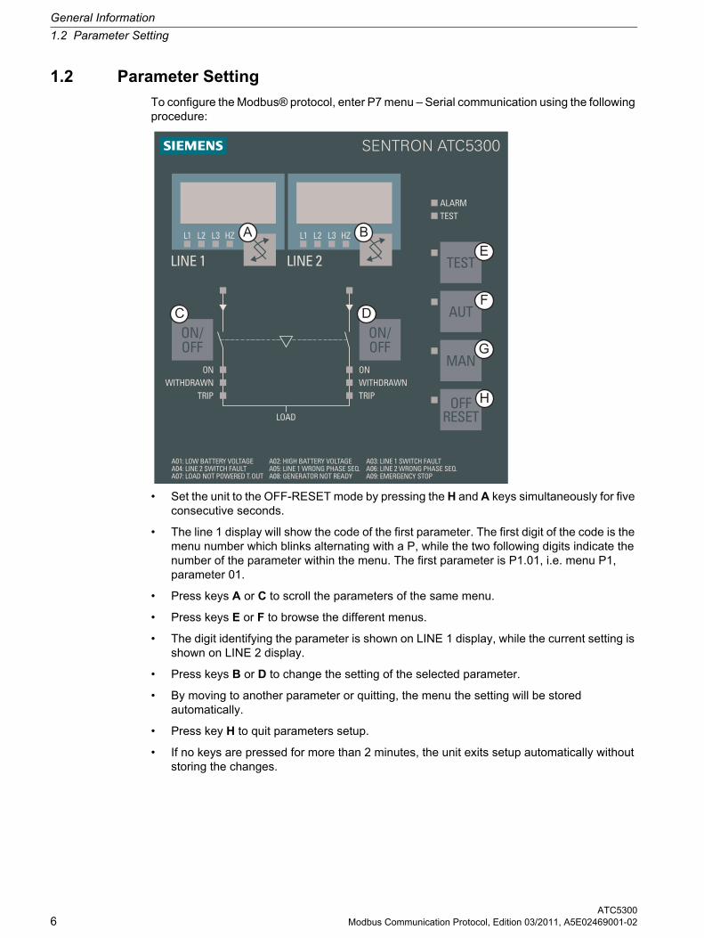
To configure the Modbus® protocol, enter P7 menu – Serial communication using the following procedure:
• Set the unit to the OFF-RESET mode by pressing the H and A keys simultaneously for five consecutive seconds.
• The line 1 display will show the code of the first parameter. The first digit of the code is the menu number which blinks alternating with a P, while the two following digits indicate the number of the parameter within the menu. The first parameter is P1.01, i.e. menu P1, parameter 01.
• Press keys A or C to scroll the parameters of the same menu.
• Press keys E or F to browse the different menus.
• The digit identifying the parameter is shown on LINE 1 display, while the current setting is shown on LINE 2 display.
• Press keys B or D to change the setting of the selected parameter.
• By moving to another parameter or quitting, the menu the setting will be stored automatically.
• Press key H to quit parameters setup.
• If no keys are pressed for more than 2 minutes, the unit exits setup automatically without storing the changes.
General Information
1.3 Menu P7 - Serial Communication
ATC5300Modbus Communication Protocol, Edition 03/2011, A5E02469001-02 7
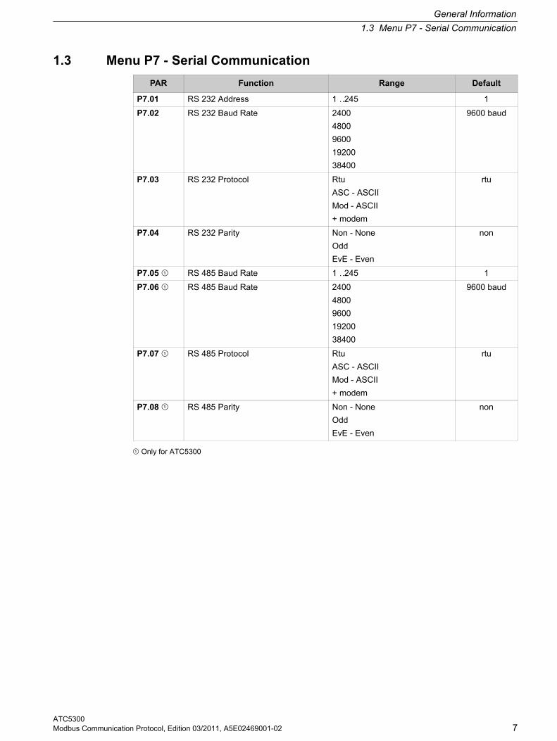
1.3 Menu P7 - Serial Communication
¿ Only for ATC5300
PAR Function Range Default
P7.01 RS 232 Address 1 …245 1
P7.02 RS 232 Baud Rate 2400
4800
9600
19200
38400
9600 baud
P7.03 RS 232 Protocol Rtu
ASC - ASCII
Mod - ASCII
+ modem
rtu
P7.04 RS 232 Parity Non - None
Odd
EvE - Even
non
P7.05 ¿ RS 485 Baud Rate 1 …245 1
P7.06 ¿ RS 485 Baud Rate 2400
4800
9600
19200
38400
9600 baud
P7.07 ¿ RS 485 Protocol Rtu
ASC - ASCII
Mod - ASCII
+ modem
rtu
P7.08 ¿ RS 485 Parity Non - None
Odd
EvE - Even
non
General Information
1.4 Modbus® RTU Protocol
ATC53008 Modbus Communication Protocol, Edition 03/2011, A5E02469001-02
1.4 Modbus® RTU Protocol
If one selects the Modbus® RTU protocol, the communication message has the following structure:
• The Address field holds the serial address of the slave destination device.
• The Function field holds the code of the function that must be executed by the slave.
• The Data field contains data sent to the slave or data received from the slave in response to a query.
• For the ATC, the maximum length for the data field is of 60 16-bit registers (120 bytes).
• The CRC field allows the master and slave devices to check the message integrity. If a message has been corrupted by electrical noise or interference, the CRC field allows the devices to recognize the error and thereby to ignore the message.
• The T1 T2 T3 sequence corresponds to a time, in which data must not be exchanged on the communication bus to allow the connected devices to recognize the end of one message and the beginning of another. This time must be at least 3.5 times the time required to send one character.
The ATC measures the time that elapse from the reception of one character and the following. If this time exceeds the time necessary to send 3.5 characters at the selected baudrate, then the next character will be considered as the first of a new message.
1.5 Modbus® Functions
The available functions are:
For instance, to read the value of the battery voltage, which resides at location 30 (1E Hex) from the ATC with serial address 01 the message to send is the following:
Whereas:
01= slave address
04 = Modbus® function "Read input register"
00 1D = Address of the required register (battery voltage) decreased by one
00 02 = Number of registers to be read beginning from address 30
E1 CD = CRC Checksum
T1T2T3
Address (8 bit)
Function (8 bit)
Data (N x 8 bit)
CRC (16 bit)T1T2T3
04 = Read input register Allows to read the ATC measures.
06 = Preset single register Allows writing parameters.
07 = Read exception Allows to read the device status.
10 = Preset multiple register Allows writing several parameters.
17 = Report slave ID Allows to read information about the ATC.
01 04 00 1D 00 02 E1 CD
General Information
1.6 Function 04: Read Input Register
ATC5300Modbus Communication Protocol, Edition 03/2011, A5E02469001-02 9
The ATC answer is the following:
Where:
01 = ATC address (Slave 01)
04 = Function requested by the master
04 = Number of bytes sent by the ATC
00 00 00 7C = Hex value of the battery voltage = 124 = 12.4 VDC
FA 65 = CRC checksum
1.6 Function 04: Read Input Register
The Modbus® function 04 allows to read one or more consecutive registers from the slave memory. The address of each measure is given in the chapter "Data Library" of this manual. As for Modbus® standard, the address in the query message must be decreased by one from the effective address reported in the table. If the measure address is not included in the table or the number of requested registers exceeds 60, the ATC will return an error code (see error table).
Master query:
In the above example slave 08 is requested for 8 consecutive registers beginning with address 10h. Thus, registers from 10h to 17h will be returned. As usual, the message ends with the CRC checksum.
Slave response:
The response is always composed of the slave address, the function code requested by the master and the contents of the requested registers. The answer ends with the CRC.
01 04 04 00 00 00 7C 65
Slave address 08h
Function 04h
MSB address 00h
LSB address 0Fh
MSB register number 00h
LSB register number 08h
MSB CRC 21h
LSB CRC 57h
Slave address 08h
Function 04h
Byte number 10h
MSB register 10h 00h
LSB register 10h 00h
— —
MSB register 17h 00h
LSB register 17h 00h
MSB CRC 5Eh
LSB CRC 83h
General Information
1.7 Function 06: Preset Single Register
ATC530010 Modbus Communication Protocol, Edition 03/2011, A5E02469001-02
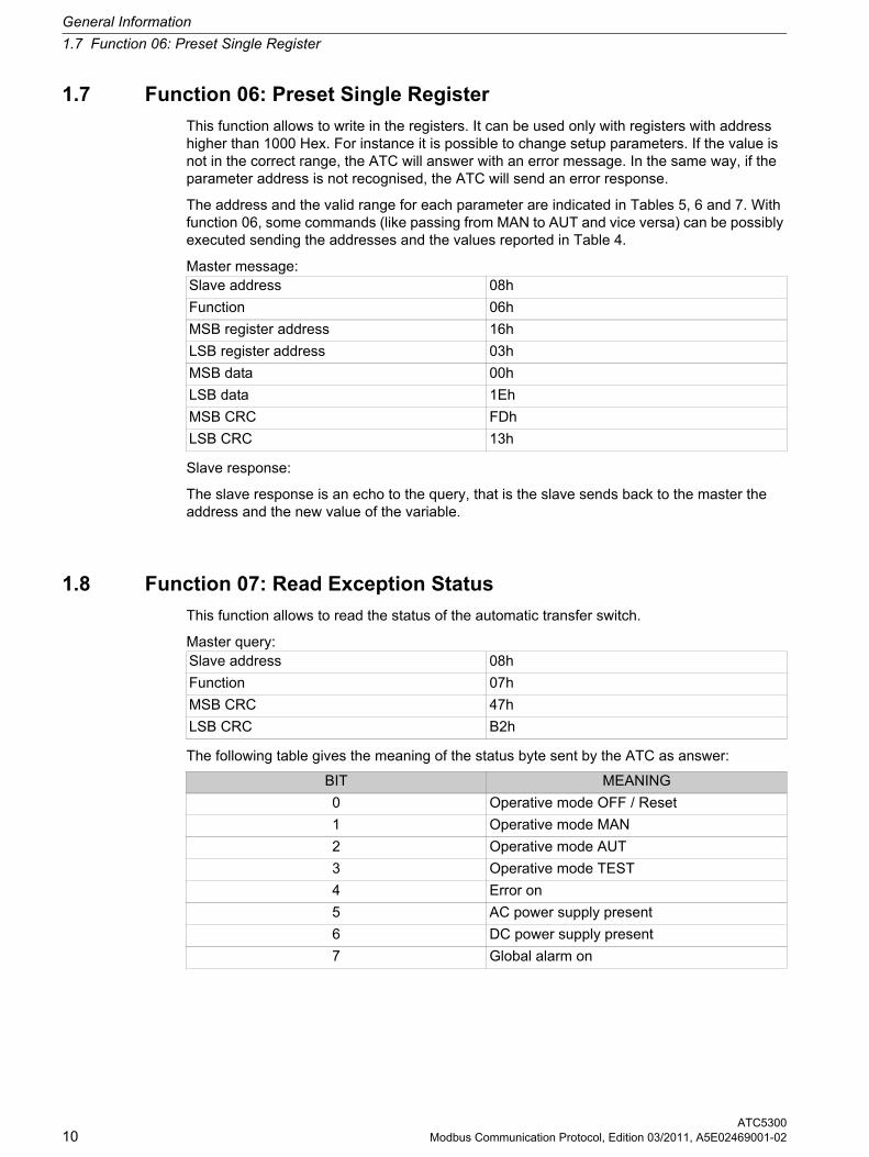
1.7 Function 06: Preset Single Register
This function allows to write in the registers. It can be used only with registers with address higher than 1000 Hex. For instance it is possible to change setup parameters. If the value is not in the correct range, the ATC will answer with an error message. In the same way, if the parameter address is not recognised, the ATC will send an error response.
The address and the valid range for each parameter are indicated in Tables 5, 6 and 7. With function 06, some commands (like passing from MAN to AUT and vice versa) can be possibly executed sending the addresses and the values reported in Table 4.
Master message:
Slave response:
The slave response is an echo to the query, that is the slave sends back to the master the address and the new value of the variable.
1.8 Function 07: Read Exception Status
This function allows to read the status of the automatic transfer switch.
Master query:
The following table gives the meaning of the status byte sent by the ATC as answer:
Slave address 08h
Function 06h
MSB register address 16h
LSB register address 03h
MSB data 00h
LSB data 1Eh
MSB CRC FDh
LSB CRC 13h
Slave address 08h
Function 07h
MSB CRC 47h
LSB CRC B2h
BIT MEANING
0 Operative mode OFF / Reset
1 Operative mode MAN
2 Operative mode AUT
3 Operative mode TEST
4 Error on
5 AC power supply present
6 DC power supply present
7 Global alarm on
General Information
1.9 Function 17: Report Slave ID
ATC5300Modbus Communication Protocol, Edition 03/2011, A5E02469001-02 11
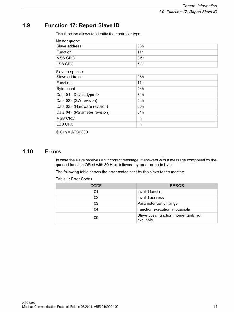
1.9 Function 17: Report Slave ID
This function allows to identify the controller type.
Master query:
Slave response:
¿ 61h = ATC5300
1.10 Errors
In case the slave receives an incorrect message, it answers with a message composed by the queried function ORed with 80 Hex, followed by an error code byte.
The following table shows the error codes sent by the slave to the master:
Table 1: Error Codes
Slave address 08h
Function 11h
MSB CRC C6h
LSB CRC 7Ch
Slave address 08h
Function 11h
Byte count 04h
Data 01 - Device type ¿ 61h
Data 02 - (SW revision) 04h
Data 03 - (Hardware revision) 00h
Data 04 - (Parameter revision) 01h
MSB CRC ..h
LSB CRC ..h
CODE ERROR
01 Invalid function
02 Invalid address
03 Parameter out of range
04 Function execution impossible
06Slave busy, function momentarily not available
General Information
1.11 Function 16: Preset Multiple Register
ATC530012 Modbus Communication Protocol, Edition 03/2011, A5E02469001-02
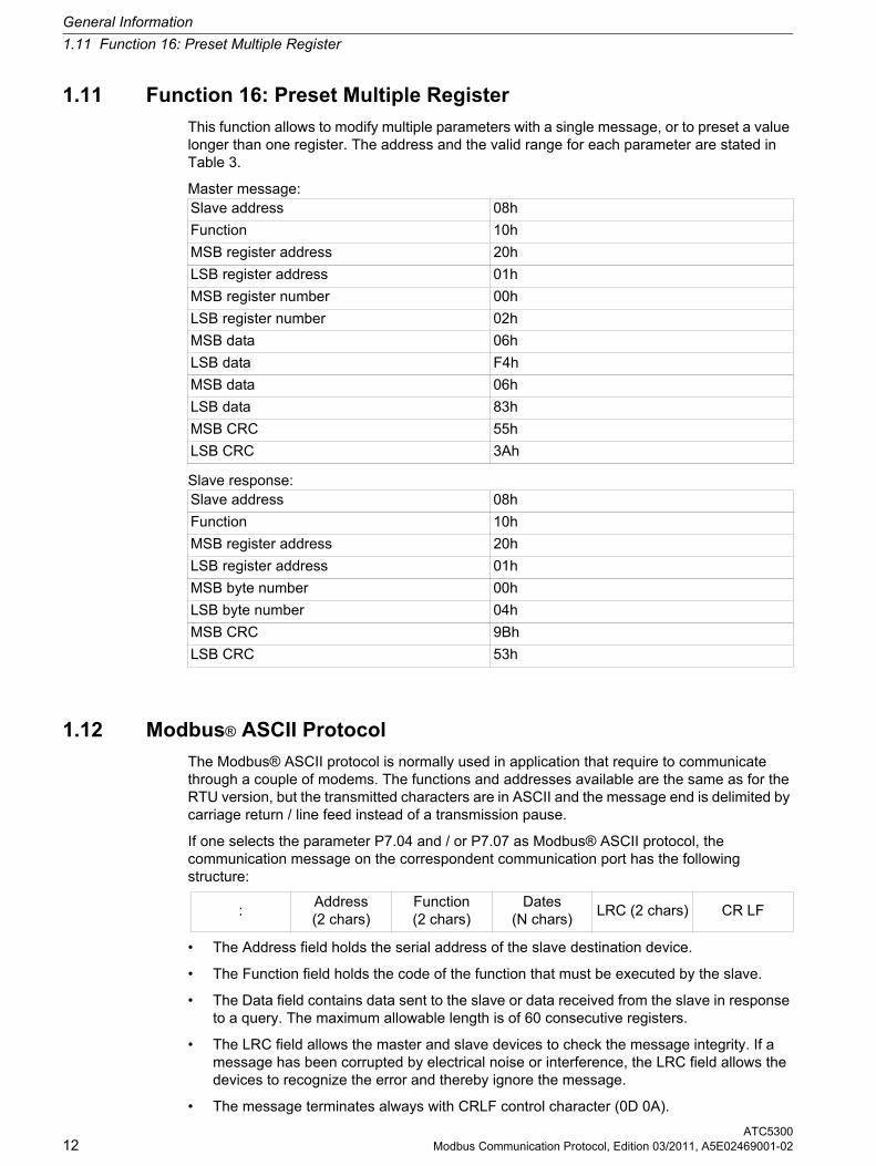
1.11 Function 16: Preset Multiple Register
This function allows to modify multiple parameters with a single message, or to preset a value longer than one register. The address and the valid range for each parameter are stated in Table 3.
Master message:
Slave response:
1.12 Modbus® ASCII Protocol
The Modbus® ASCII protocol is normally used in application that require to communicate through a couple of modems. The functions and addresses available are the same as for the RTU version, but the transmitted characters are in ASCII and the message end is delimited by carriage return / line feed instead of a transmission pause.
If one selects the parameter P7.04 and / or P7.07 as Modbus® ASCII protocol, the communication message on the correspondent communication port has the following structure:
• The Address field holds the serial address of the slave destination device.
• The Function field holds the code of the function that must be executed by the slave.
• The Data field contains data sent to the slave or data received from the slave in response to a query. The maximum allowable length is of 60 consecutive registers.
• The LRC field allows the master and slave devices to check the message integrity. If a message has been corrupted by electrical noise or interference, the LRC field allows the devices to recognize the error and thereby ignore the message.
• The message terminates always with CRLF control character (0D 0A).
Slave address 08h
Function 10h
MSB register address 20h
LSB register address 01h
MSB register number 00h
LSB register number 02h
MSB data 06h
LSB data F4h
MSB data 06h
LSB data 83h
MSB CRC 55h
LSB CRC 3Ah
Slave address 08h
Function 10h
MSB register address 20h
LSB register address 01h
MSB byte number 00h
LSB byte number 04h
MSB CRC 9Bh
LSB CRC 53h
:Address (2 chars)
Function (2 chars)
Dates (N chars)
LRC (2 chars) CR LF
General Information
1.12 Modbus® ASCII Protocol
ATC5300Modbus Communication Protocol, Edition 03/2011, A5E02469001-02 13
Example:
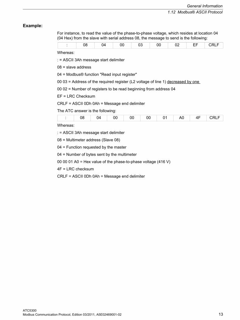
For instance, to read the value of the phase-to-phase voltage, which resides at location 04 (04 Hex) from the slave with serial address 08, the message to send is the following:
Whereas:
: = ASCII 3Ah message start delimiter
08 = slave address
04 = Modbus® function "Read input register"
00 03 = Address of the required register (L2 voltage of line 1) decreased by one
00 02 = Number of registers to be read beginning from address 04
EF = LRC Checksum
CRLF = ASCII 0Dh 0Ah = Message end delimiter
The ATC answer is the following:
Whereas:
: = ASCII 3Ah message start delimiter
08 = Multimeter address (Slave 08)
04 = Function requested by the master
04 = Number of bytes sent by the multimeter
00 00 01 A0 = Hex value of the phase-to-phase voltage (416 V)
4F = LRC checksum
CRLF = ASCII 0Dh 0Ah = Message end delimiter
: 08 04 00 03 00 02 EF CRLF
: 08 04 00 00 00 01 A0 4F CRLF
General Information
1.13 CRC Calculation (CHECKSUM for RTU)
ATC530014 Modbus Communication Protocol, Edition 03/2011, A5E02469001-02
1.13 CRC Calculation (CHECKSUM for RTU)
CRC Calculation Workflow
XOR = exclusive or
n = number of information bits
POLY = calculation polynomial of the CRC 16 = 1010 0000 0000 0001
(Generating polynomial = 1 + x 2 + x 15 + x 16)
In the CRC 16, the 1st byte transmitted is the least significant one.
CRC x or B Y TE = CRC
n = 0
CRC right s h ift
carry over
CRC x or PO LY = CRC
n = n + 1
nex t BYTE
end mes sage
End
n > 7
H ex FFFF = CRC
n o
no
ye s
yes
General Information
1.13 CRC Calculation (CHECKSUM for RTU)
ATC5300Modbus Communication Protocol, Edition 03/2011, A5E02469001-02 15
Example of CRC calculation:
Frame = 0207h
CRC initialization 1111 1111 1111 1111
Load the first byte 0000 0010
Execute xor with the first 1111 1111 1111 1101
Byte of the frame
Execute 1st right shift 0111 1111 1111 1110 1
Carry=1, load polynominal 1010 0000 0000 0001
Execute xor with the polynominal 1101 1111 1111 1111
Execute 2nd right shift 0110 1111 1111 1111 1
Carry=1, load polynominal 1010 0000 0000 0001
Execute xor with the polynominal 1100 1111 1111 1110
Execute 3rd right shift 0110 0111 1111 1111 0
Execute 4th right shift 0011 0011 1111 1111 1
Carry=1, load polynominal 1010 0000 0000 0001
Execute xor with the polynominal 1001 0011 1111 1110
Execute 5th right shift 0100 1001 1111 1111 0
Execute 6th right shift 0010 0100 1111 1111 1
Carry=1, load polynominal 1010 0000 0000 0001
Execute xor with the polynominal 1000 0100 1111 1110
Execute 7th right shift 0100 0010 0111 1111 0
Execute 8th right shift 0010 0001 0011 1111 1
Carry=1, load polynominal 1010 0000 0000 0001
Load the second byte of the frame 0000 0111
Execute xor with the polynominal 1000 0001 0011 1001
Second byte of the frame
Execute 1st right shift 0100 0000 1001 1100 1
Carry=1, load polynominal 1010 0000 0000 0001
Execute xor with the polynominal 1110 0000 1001 1101
Execute 2nd right shift 0111 0000 0100 1110 1
Carry=1, load polynominal 1010 0000 0000 0001
Execute xor with the polynominal 1101 0000 0100 1111
Execute 3rd right shift 0110 1000 0010 0111 1
Carry=1, load polynominal 1010 0000 0000 0001
Execute xor with the polynominal 1100 1000 0010 0110
Execute 4th right shift 0110 0100 0001 0011 0
Execute 5th right shift 0010 0100 0000 1001 1
Carry=1, load polynominal 1010 0000 0000 0001
Execute xor with the polynominal 1001 0010 0000 1000
Execute 6th right shift 0100 1001 0000 0100 0
Execute 7th right shift 0010 0100 1000 0010 0
General Information
1.14 Technical Support
ATC530016 Modbus Communication Protocol, Edition 03/2011, A5E02469001-02
1.14 Technical Support
For further assistance, refer to:
Technical Support on the Internet:
Internet address of Technical Support
http://www.siemens.com/lowvoltage/technical-support
Execute 8th right shift 0001 0010 0100 0001 0
CRC Result 0001 0010 0100 0001
|<------- 12h ------->| |<------- 41h ------->|
ATC5300Modbus Communication Protocol, Edition 03/2011, A5E02469001-02 17
Data Library 2Data Library
2.1 Data Provided
Data provided by Serial Communication Protocol (to be used with functions 03 and 04)
ADDRESS WORDS MEASURE UNIT FORMAT
02h 2 Voltage of line 1 L1-N V Unsigned long
04h 2 Voltage of line 1 L2-N V Unsigned long
06h 2 Voltage of line 1 L3-N V Unsigned long
08h 2 Voltage of line 1 L1-L2 V Unsigned long
0Ah 2 Voltage of line 1 L2-L3 V Unsigned long
0Ch 2 Voltage of line 1 L3-L1 V Unsigned long
0Eh 2 Voltage of line 2 L1-N V Unsigned long
10h 2 Voltage of line 2 L2-N V Unsigned long
12h 2 Voltage of line 2 L3-N V Unsigned long
14h 2 Voltage of line 2 L1-L2 V Unsigned long
16h 2 Voltage of line 2 L2-L3 V Unsigned long
18h 2 Voltage of line 2 L3-L1 V Unsigned long
1Ah 2 Frequency of line 1 Hz / 10 Unsigned long
1Ch 2 Frequency of line 2 Hz / 10 Unsigned long
1Eh 2 Battery voltage (DC power supply) VDC / 10 Unsigned long
20h 2 Total operation time s Unsigned long
22h 2 Line 1 ok total time s Unsigned long
24h 2 Line 2 ok total time s Unsigned long
26h 2 Line 1 not ok total time s Unsigned long
28h 2 Line 2 not ok total time s Unsigned long
2Ah 2 Line 1 breaker closed total time s Unsigned long
2Ch 2 Line 2 breaker closed total time s Unsigned long
2Eh 2 Breaker opened total time s Unsigned long
30h 2 (not used) — Unsigned long
32h 2Number of operations of line 1 breaker in AUT
nr Unsigned long
34h 2Number of operations of line 2 breaker in AUT
nr Unsigned long
36h 2Number of operations of line 1 breaker in MAN
nr Unsigned long
Data Library
2.2 Status Bits
ATC530018 Modbus Communication Protocol, Edition 03/2011, A5E02469001-02
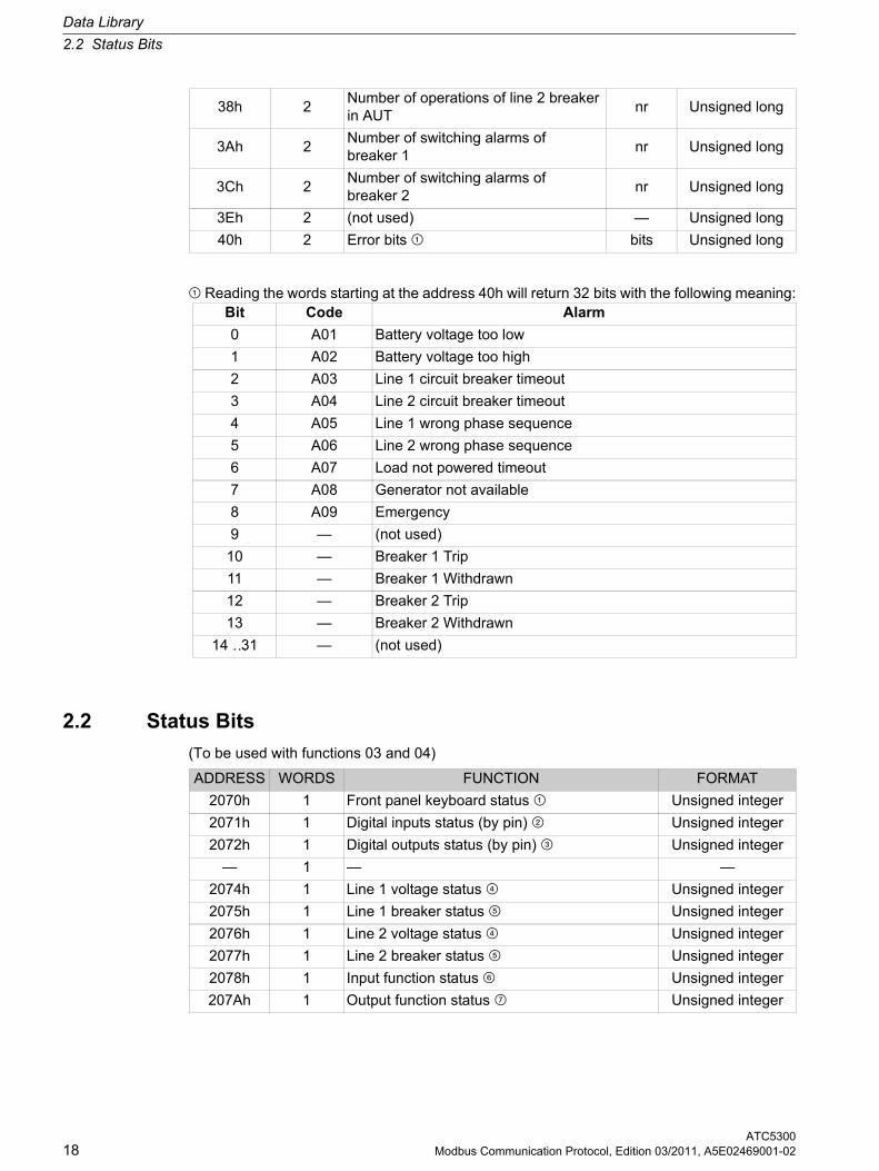
¿ Reading the words starting at the address 40h will return 32 bits with the following meaning:
2.2 Status Bits
(To be used with functions 03 and 04)
38h 2Number of operations of line 2 breaker in AUT
nr Unsigned long
3Ah 2Number of switching alarms of breaker 1
nr Unsigned long
3Ch 2Number of switching alarms of breaker 2
nr Unsigned long
3Eh 2 (not used) — Unsigned long
40h 2 Error bits ¿ bits Unsigned long
Bit Code Alarm
0 A01 Battery voltage too low
1 A02 Battery voltage too high
2 A03 Line 1 circuit breaker timeout
3 A04 Line 2 circuit breaker timeout
4 A05 Line 1 wrong phase sequence
5 A06 Line 2 wrong phase sequence
6 A07 Load not powered timeout
7 A08 Generator not available
8 A09 Emergency
9 — (not used)
10 — Breaker 1 Trip
11 — Breaker 1 Withdrawn
12 — Breaker 2 Trip
13 — Breaker 2 Withdrawn
14 …31 — (not used)
ADDRESS WORDS FUNCTION FORMAT
2070h 1 Front panel keyboard status ¿ Unsigned integer
2071h 1 Digital inputs status (by pin) À Unsigned integer
2072h 1 Digital outputs status (by pin) Á Unsigned integer
— 1 — —
2074h 1 Line 1 voltage status  Unsigned integer
2075h 1 Line 1 breaker status à Unsigned integer
2076h 1 Line 2 voltage status  Unsigned integer
2077h 1 Line 2 breaker status à Unsigned integer
2078h 1 Input function status Ä Unsigned integer
207Ah 1 Output function status Å Unsigned integer
Data Library
2.2 Status Bits
ATC5300Modbus Communication Protocol, Edition 03/2011, A5E02469001-02 19
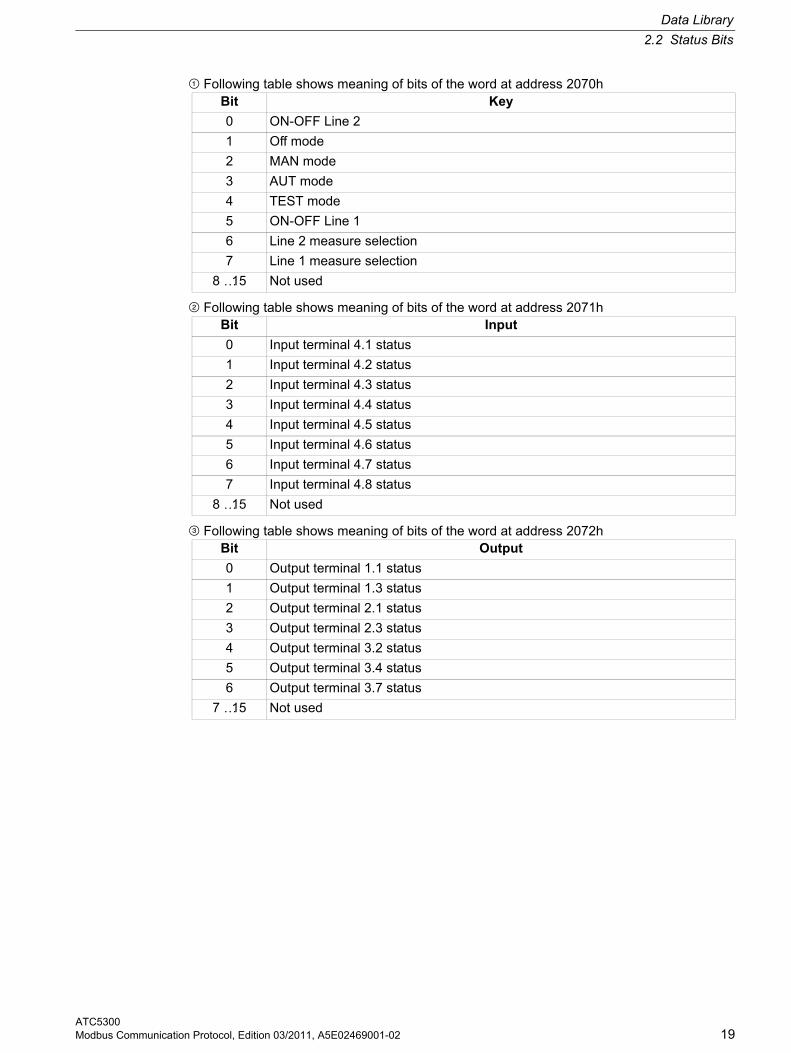
¿ Following table shows meaning of bits of the word at address 2070h
À Following table shows meaning of bits of the word at address 2071h
Á Following table shows meaning of bits of the word at address 2072h
Bit Key
0 ON-OFF Line 2
1 Off mode
2 MAN mode
3 AUT mode
4 TEST mode
5 ON-OFF Line 1
6 Line 2 measure selection
7 Line 1 measure selection
8 …15 Not used
Bit Input
0 Input terminal 4.1 status
1 Input terminal 4.2 status
2 Input terminal 4.3 status
3 Input terminal 4.4 status
4 Input terminal 4.5 status
5 Input terminal 4.6 status
6 Input terminal 4.7 status
7 Input terminal 4.8 status
8 …15 Not used
Bit Output
0 Output terminal 1.1 status
1 Output terminal 1.3 status
2 Output terminal 2.1 status
3 Output terminal 2.3 status
4 Output terminal 3.2 status
5 Output terminal 3.4 status
6 Output terminal 3.7 status
7 …15 Not used
Data Library
2.2 Status Bits
ATC530020 Modbus Communication Protocol, Edition 03/2011, A5E02469001-02
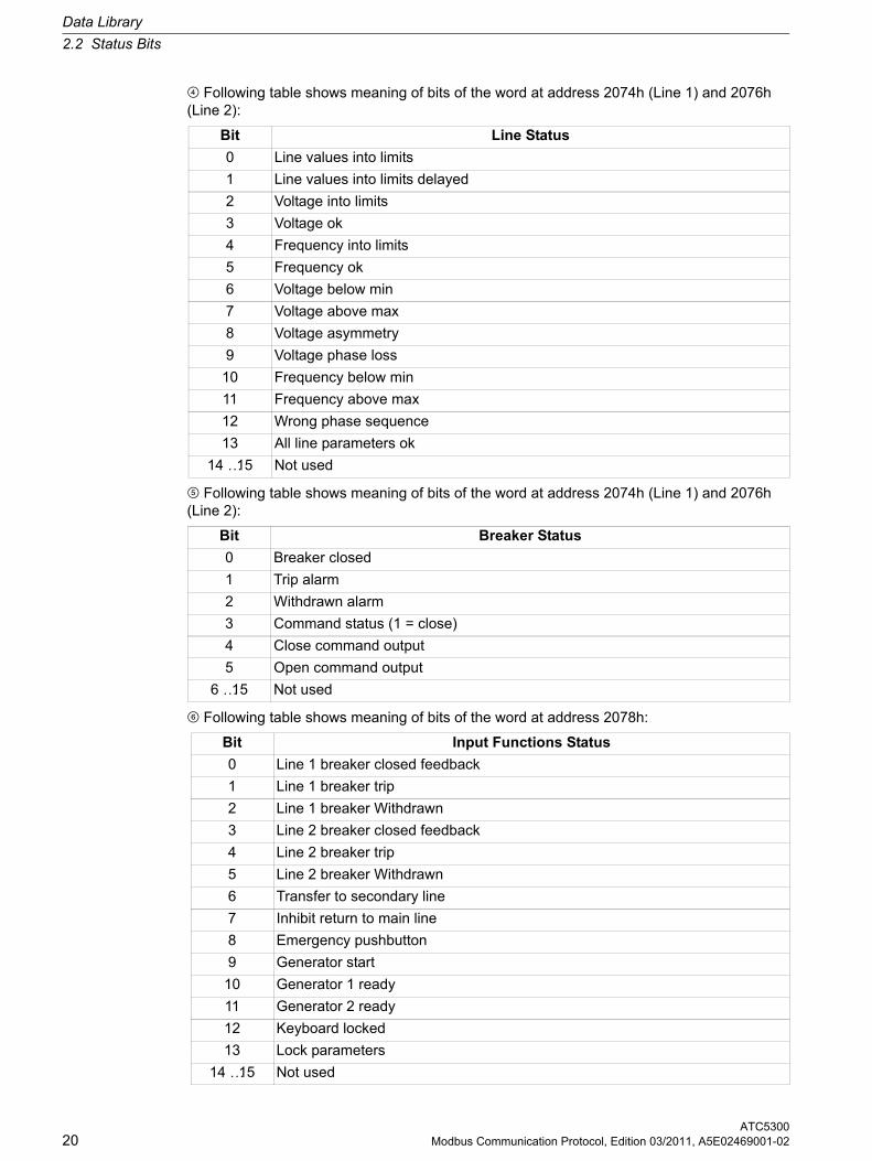
 Following table shows meaning of bits of the word at address 2074h (Line 1) and 2076h (Line 2):
à Following table shows meaning of bits of the word at address 2074h (Line 1) and 2076h (Line 2):
Ä Following table shows meaning of bits of the word at address 2078h:
Bit Line Status
0 Line values into limits
1 Line values into limits delayed
2 Voltage into limits
3 Voltage ok
4 Frequency into limits
5 Frequency ok
6 Voltage below min
7 Voltage above max
8 Voltage asymmetry
9 Voltage phase loss
10 Frequency below min
11 Frequency above max
12 Wrong phase sequence
13 All line parameters ok
14 …15 Not used
Bit Breaker Status
0 Breaker closed
1 Trip alarm
2 Withdrawn alarm
3 Command status (1 = close)
4 Close command output
5 Open command output
6 …15 Not used
Bit Input Functions Status
0 Line 1 breaker closed feedback
1 Line 1 breaker trip
2 Line 1 breaker Withdrawn
3 Line 2 breaker closed feedback
4 Line 2 breaker trip
5 Line 2 breaker Withdrawn
6 Transfer to secondary line
7 Inhibit return to main line
8 Emergency pushbutton
9 Generator start
10 Generator 1 ready
11 Generator 2 ready
12 Keyboard locked
13 Lock parameters
14 …15 Not used
Data Library
2.3 Commands
ATC5300Modbus Communication Protocol, Edition 03/2011, A5E02469001-02 21
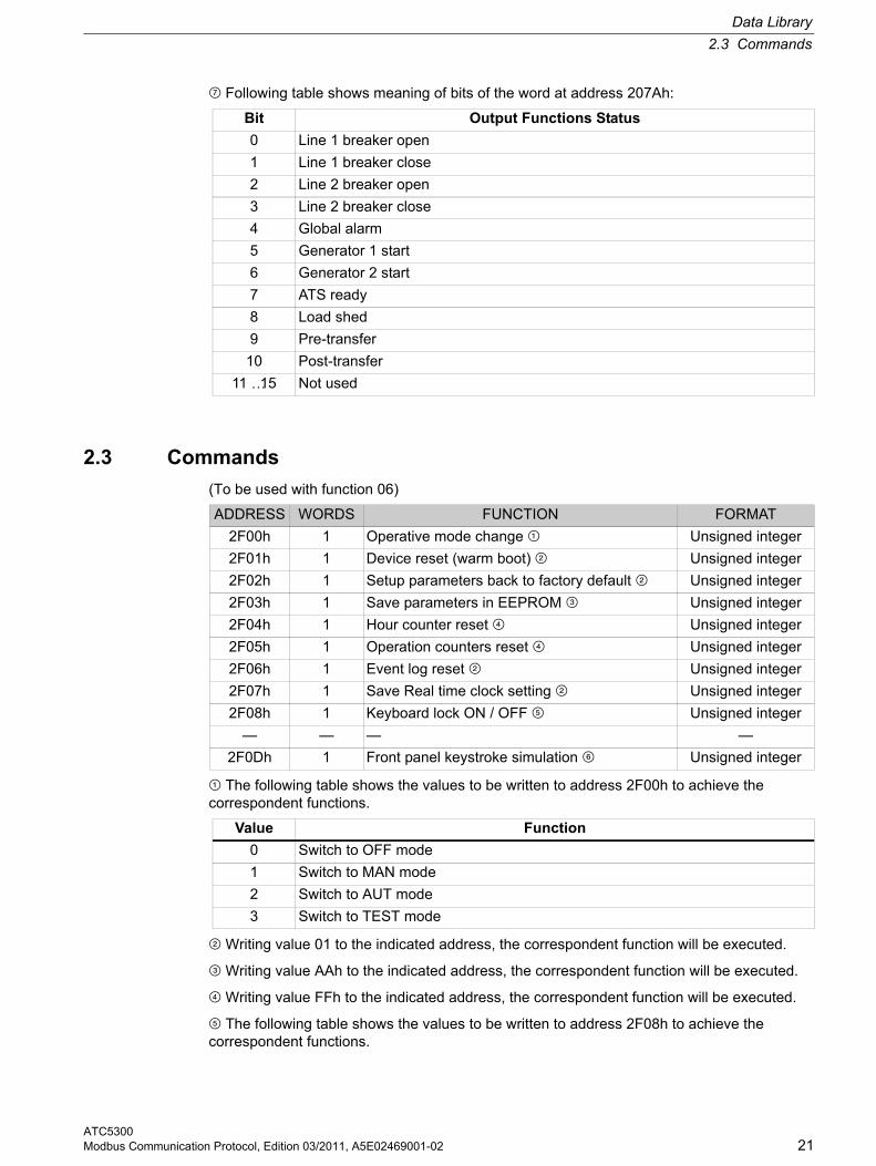
Å Following table shows meaning of bits of the word at address 207Ah:
2.3 Commands
(To be used with function 06)
¿ The following table shows the values to be written to address 2F00h to achieve the correspondent functions.
À Writing value 01 to the indicated address, the correspondent function will be executed.
Á Writing value AAh to the indicated address, the correspondent function will be executed.
 Writing value FFh to the indicated address, the correspondent function will be executed.
à The following table shows the values to be written to address 2F08h to achieve the correspondent functions.
Bit Output Functions Status
0 Line 1 breaker open
1 Line 1 breaker close
2 Line 2 breaker open
3 Line 2 breaker close
4 Global alarm
5 Generator 1 start
6 Generator 2 start
7 ATS ready
8 Load shed
9 Pre-transfer
10 Post-transfer
11 …15 Not used
ADDRESS WORDS FUNCTION FORMAT
2F00h 1 Operative mode change ¿ Unsigned integer
2F01h 1 Device reset (warm boot) À Unsigned integer
2F02h 1 Setup parameters back to factory default À Unsigned integer
2F03h 1 Save parameters in EEPROM Á Unsigned integer
2F04h 1 Hour counter reset  Unsigned integer
2F05h 1 Operation counters reset  Unsigned integer
2F06h 1 Event log reset À Unsigned integer
2F07h 1 Save Real time clock setting À Unsigned integer
2F08h 1 Keyboard lock ON / OFF Ã Unsigned integer
— — — —
2F0Dh 1 Front panel keystroke simulation Ä Unsigned integer
Value Function
0 Switch to OFF mode
1 Switch to MAN mode
2 Switch to AUT mode
3 Switch to TEST mode
Data Library
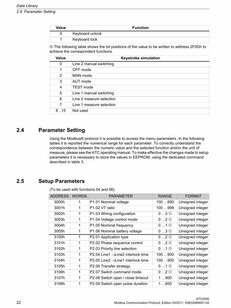
2.4 Parameter Setting
ATC530022 Modbus Communication Protocol, Edition 03/2011, A5E02469001-02
Ä The following table shows the bit positions of the value to be written to address 2F0Dh to achieve the correspondent functions.
2.4 Parameter Setting
Using the Modbus® protocol it is possible to access the menu parameters. In the following tables it is reported the numerical range for each parameter. To correctly understand the correspondence between the numeric value and the selected function and/or the unit of measure, please see the ATC operating manual. To make effective the changes made to setup parameters it is necessary to store the values in EEPROM, using the dedicated command described in table 3.
2.5 Setup Parameters
(To be used with functions 04 and 06)
Value Function
0 Keyboard unlock
1 Keyboard lock
Value Keystroke simulation
0 Line 2 manual switching
1 OFF mode
2 MAN mode
3 AUT mode
4 TEST mode
5 Line 1 manual switching
6 Line 2 measure selection
7 Line 1 measure selection
8 …15 Not used
ADDRESS WORDS PARAMETER RANGE FORMAT
3000h 1 P1.01 Nominal voltage 100 …690 Unsigned integer
3001h 1 P1.02 VT ratio 100 …999 Unsigned integer
3002h 1 P1.03 Wiring configuration 0 …3 ¿ Unsigned integer
3003h 1 P1.04 Voltage control mode 0 …2 ¿ Unsigned integer
3004h 1 P1.05 Nominal frequency 0 …1 ¿ Unsigned integer
3005h 1 P1.06 Nominal battery voltage 0 …3 ¿ Unsigned integer
3100h 1 P2.01 Application type 0 …2 ¿ Unsigned integer
3101h 1 P2.02 Phase sequence control 0 …2 ¿ Unsigned integer
3102h 1 P2.03 Priority line selection 0 …1 ¿ Unsigned integer
3103h 1 P2.04 Line1 → Line2 interlock time 100 …900 Unsigned integer
3104h 1 P2.05 Line2 → Line1 interlock time 100 …900 Unsigned integer
3105h 1 P2.06 Transfer strategy 0 …1 ¿ Unsigned integer
3106h 1 P2.07 Switch command mode 0 …2 ¿ Unsigned integer
3107h 1 P2.08 Switch open / close timeout 1 …900 Unsigned integer
3108h 1 P2.09 Switch open pulse duration 1 …600 Unsigned integer
Data Library
2.5 Setup Parameters
ATC5300Modbus Communication Protocol, Edition 03/2011, A5E02469001-02 23
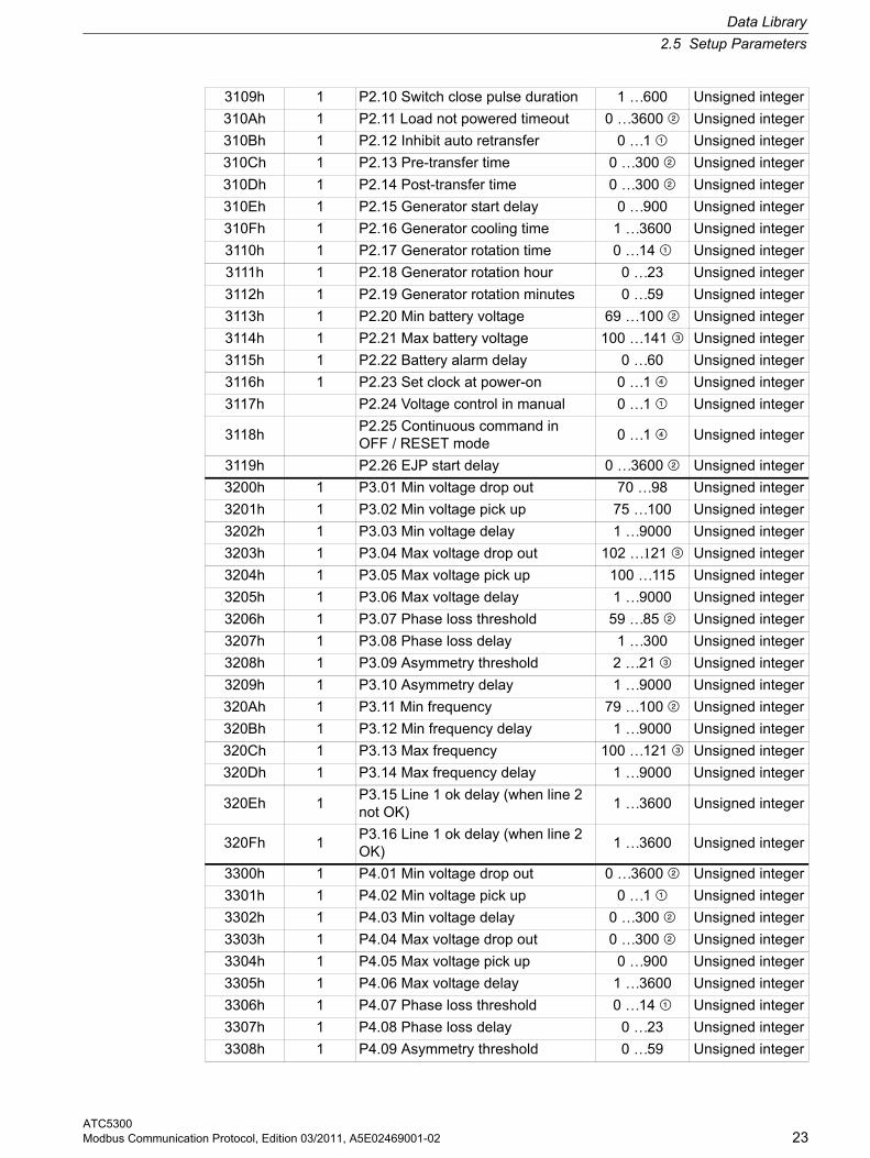
3109h 1 P2.10 Switch close pulse duration 1 …600 Unsigned integer
310Ah 1 P2.11 Load not powered timeout 0 …3600 À Unsigned integer
310Bh 1 P2.12 Inhibit auto retransfer 0 …1 ¿ Unsigned integer
310Ch 1 P2.13 Pre-transfer time 0 …300 À Unsigned integer
310Dh 1 P2.14 Post-transfer time 0 …300 À Unsigned integer
310Eh 1 P2.15 Generator start delay 0 …900 Unsigned integer
310Fh 1 P2.16 Generator cooling time 1 …3600 Unsigned integer
3110h 1 P2.17 Generator rotation time 0 …14 ¿ Unsigned integer
3111h 1 P2.18 Generator rotation hour 0 …23 Unsigned integer
3112h 1 P2.19 Generator rotation minutes 0 …59 Unsigned integer
3113h 1 P2.20 Min battery voltage 69 …100 À Unsigned integer
3114h 1 P2.21 Max battery voltage 100 …141 Á Unsigned integer
3115h 1 P2.22 Battery alarm delay 0 …60 Unsigned integer
3116h 1 P2.23 Set clock at power-on 0 …1 Â Unsigned integer
3117h P2.24 Voltage control in manual 0 …1 ¿ Unsigned integer
3118hP2.25 Continuous command in OFF / RESET mode
0 …1 Â Unsigned integer
3119h P2.26 EJP start delay 0 …3600 À Unsigned integer
3200h 1 P3.01 Min voltage drop out 70 …98 Unsigned integer
3201h 1 P3.02 Min voltage pick up 75 …100 Unsigned integer
3202h 1 P3.03 Min voltage delay 1 …9000 Unsigned integer
3203h 1 P3.04 Max voltage drop out 102 …121 Á Unsigned integer
3204h 1 P3.05 Max voltage pick up 100 …115 Unsigned integer
3205h 1 P3.06 Max voltage delay 1 …9000 Unsigned integer
3206h 1 P3.07 Phase loss threshold 59 …85 À Unsigned integer
3207h 1 P3.08 Phase loss delay 1 …300 Unsigned integer
3208h 1 P3.09 Asymmetry threshold 2 …21 Á Unsigned integer
3209h 1 P3.10 Asymmetry delay 1 …9000 Unsigned integer
320Ah 1 P3.11 Min frequency 79 …100 À Unsigned integer
320Bh 1 P3.12 Min frequency delay 1 …9000 Unsigned integer
320Ch 1 P3.13 Max frequency 100 …121 Á Unsigned integer
320Dh 1 P3.14 Max frequency delay 1 …9000 Unsigned integer
320Eh 1P3.15 Line 1 ok delay (when line 2 not OK)
1 …3600 Unsigned integer
320Fh 1P3.16 Line 1 ok delay (when line 2 OK)
1 …3600 Unsigned integer
3300h 1 P4.01 Min voltage drop out 0 …3600 À Unsigned integer
3301h 1 P4.02 Min voltage pick up 0 …1 ¿ Unsigned integer
3302h 1 P4.03 Min voltage delay 0 …300 À Unsigned integer
3303h 1 P4.04 Max voltage drop out 0 …300 À Unsigned integer
3304h 1 P4.05 Max voltage pick up 0 …900 Unsigned integer
3305h 1 P4.06 Max voltage delay 1 …3600 Unsigned integer
3306h 1 P4.07 Phase loss threshold 0 …14 ¿ Unsigned integer
3307h 1 P4.08 Phase loss delay 0 …23 Unsigned integer
3308h 1 P4.09 Asymmetry threshold 0 …59 Unsigned integer
Data Library
2.5 Setup Parameters
ATC530024 Modbus Communication Protocol, Edition 03/2011, A5E02469001-02
3309h 1 P4.10 Asymmetry delay 69 …100 À Unsigned integer
330Ah 1 P4.11 Min frequency 100 …141 Á Unsigned integer
330Bh 1 P4.12 Min frequency delay 0 …60 Unsigned integer
330Ch 1 P4.13 Max frequency 0 …1 Â Unsigned integer
330Dh 1 P4.14 Max frequency delay 0 …1 ¿ Unsigned integer
330Eh 1P4.15 Line 1 ok delay (when line 1 not OK)
1 …3600 Unsigned integer
330Fh 1P4.16 Line 1 ok delay (when line 1 OK)
1 …3600 Unsigned integer
3400h 1P5.01 Programmable Input 1 function
0 …19 ¿ Unsigned integer
3401h 1P5.02 Programmable Input 1 function
0 …19 ¿ Unsigned integer
3402h 1P5.03 Programmable Input 1 function
0 …19 ¿ Unsigned integer
3403h 1P5.04 Programmable Input 1 function
0 …19 ¿ Unsigned integer
3404h 1P5.05 Programmable Input 1 function
0 …19 ¿ Unsigned integer
3405h 1P5.06 Programmable Input 1 function
0 …19 ¿ Unsigned integer
3406h 1P5.07 Programmable Input 1 function
0 …19 ¿ Unsigned integer
3407h 1P5.08 Programmable Input 1 function
0 …19 ¿ Unsigned integer
3500h 1P6.01 Programmable output 1 function
0 …14 ¿ Unsigned integer
3501h 1P6.02 Programmable output 1 function
0 …14 ¿ Unsigned integer
3502h 1P6.03 Programmable output 1 function
0 …14 ¿ Unsigned integer
3503h 1P6.04 Programmable output 1 function
0 …14 ¿ Unsigned integer
3504h 1P6.05 Programmable output 1 function
0 …14 ¿ Unsigned integer
3505h 1P6.06 Programmable output 1 function
0 …14 ¿ Unsigned integer
3506h 1P6.07 Programmable output 1 function
0 …14 ¿ Unsigned integer
3600h 1 P7.01 RS 232 serial address 1 …245 Unsigned integer
3601h 1 P7.02 RS 232 serial speed 0 …4 ¿ Unsigned integer
3602h 1 P7.03 RS 232 protocol 0 …4 ¿ Unsigned integer
3603h 1 P7.04 RS 232 parity 0 …4 ¿ Unsigned integer
3604h 1 P7.05 RS 485 serial address 1 …245 Unsigned integer
3605h 1 P7.06 RS 485 serial speed 0 …4 ¿ Unsigned integer
3606h 1 P7.07 RS 485 protocol 0 …4 ¿ Unsigned integer
3607h 1 P7.08 RS 485 parity 0 …4 ¿ Unsigned integer
3700h 1 P8.01 Automatic test enable 0 …1 ¿ Unsigned integer
Data Library
2.6 Real Time Clock
ATC5300Modbus Communication Protocol, Edition 03/2011, A5E02469001-02 25
¿ The association between the numerical value and the function has to be done in a sequential way, considering the function listed on the operative manual. The first function is obtained by setting 0, while the last function by setting the maximum value allowed by the range.
À To select OFF, set the minimum numerical value allowed by range.
Á To select OFF, set the maximum numerical value allowed by range.
 The association between the numerical value and the function has to be done in a sequential way, considering the function listed on the operative manual. The first function is obtained by setting the maximum value allowed by the range, while the last function by setting value 0.
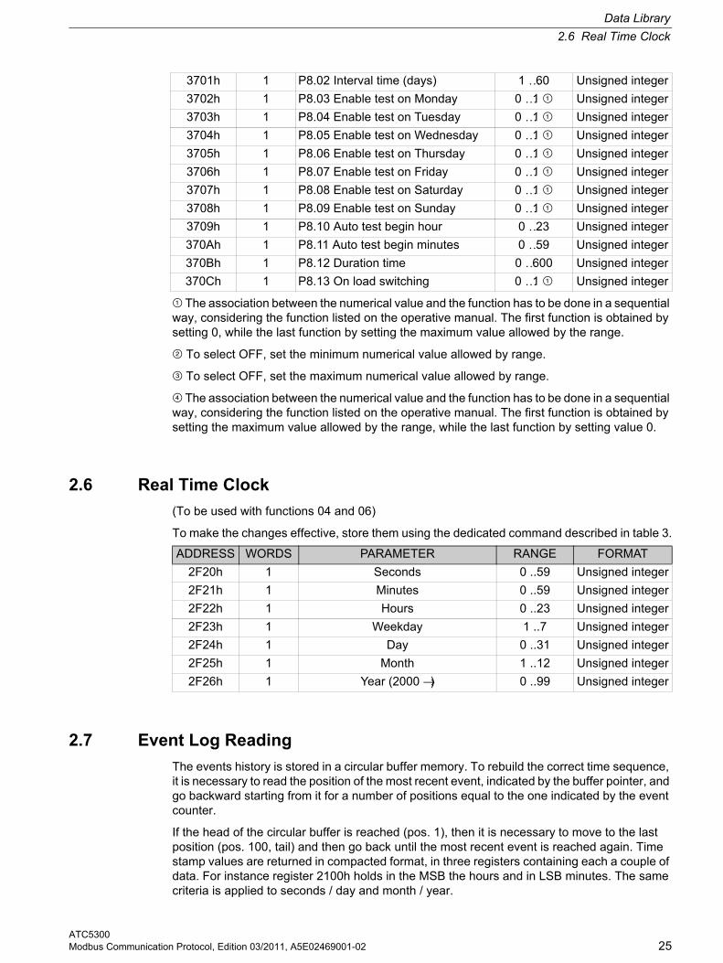
2.6 Real Time Clock
(To be used with functions 04 and 06)
To make the changes effective, store them using the dedicated command described in table 3.
2.7 Event Log Reading
The events history is stored in a circular buffer memory. To rebuild the correct time sequence, it is necessary to read the position of the most recent event, indicated by the buffer pointer, and go backward starting from it for a number of positions equal to the one indicated by the event counter.
If the head of the circular buffer is reached (pos. 1), then it is necessary to move to the last position (pos. 100, tail) and then go back until the most recent event is reached again. Time stamp values are returned in compacted format, in three registers containing each a couple of data. For instance register 2100h holds in the MSB the hours and in LSB minutes. The same criteria is applied to seconds / day and month / year.
3701h 1 P8.02 Interval time (days) 1 …60 Unsigned integer
3702h 1 P8.03 Enable test on Monday 0 …1 ¿ Unsigned integer
3703h 1 P8.04 Enable test on Tuesday 0 …1 ¿ Unsigned integer
3704h 1 P8.05 Enable test on Wednesday 0 …1 ¿ Unsigned integer
3705h 1 P8.06 Enable test on Thursday 0 …1 ¿ Unsigned integer
3706h 1 P8.07 Enable test on Friday 0 …1 ¿ Unsigned integer
3707h 1 P8.08 Enable test on Saturday 0 …1 ¿ Unsigned integer
3708h 1 P8.09 Enable test on Sunday 0 …1 ¿ Unsigned integer
3709h 1 P8.10 Auto test begin hour 0 …23 Unsigned integer
370Ah 1 P8.11 Auto test begin minutes 0 …59 Unsigned integer
370Bh 1 P8.12 Duration time 0 …600 Unsigned integer
370Ch 1 P8.13 On load switching 0 …1 ¿ Unsigned integer
ADDRESS WORDS PARAMETER RANGE FORMAT
2F20h 1 Seconds 0 ..59 Unsigned integer
2F21h 1 Minutes 0 ..59 Unsigned integer
2F22h 1 Hours 0 ..23 Unsigned integer
2F23h 1 Weekday 1 ..7 Unsigned integer
2F24h 1 Day 0 ..31 Unsigned integer
2F25h 1 Month 1 ..12 Unsigned integer
2F26h 1 Year (2000 →) 0 ..99 Unsigned integer
Data Library
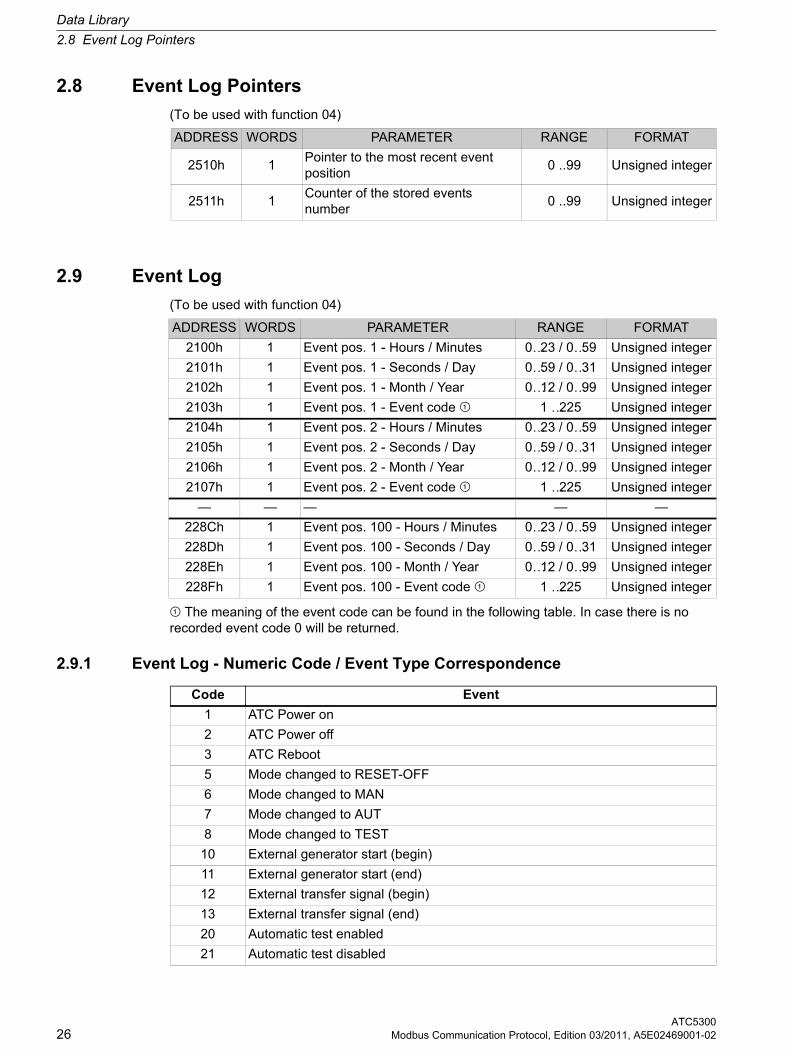
2.8 Event Log Pointers
ATC530026 Modbus Communication Protocol, Edition 03/2011, A5E02469001-02
2.8 Event Log Pointers
(To be used with function 04)
2.9 Event Log
(To be used with function 04)
¿ The meaning of the event code can be found in the following table. In case there is no recorded event code 0 will be returned.
2.9.1 Event Log - Numeric Code / Event Type Correspondence
ADDRESS WORDS PARAMETER RANGE FORMAT
2510h 1Pointer to the most recent event position
0 ..99 Unsigned integer
2511h 1Counter of the stored events number
0 ..99 Unsigned integer
ADDRESS WORDS PARAMETER RANGE FORMAT
2100h 1 Event pos. 1 - Hours / Minutes 0…23 / 0…59 Unsigned integer
2101h 1 Event pos. 1 - Seconds / Day 0…59 / 0…31 Unsigned integer
2102h 1 Event pos. 1 - Month / Year 0…12 / 0…99 Unsigned integer
2103h 1 Event pos. 1 - Event code ¿ 1 …225 Unsigned integer
2104h 1 Event pos. 2 - Hours / Minutes 0…23 / 0…59 Unsigned integer
2105h 1 Event pos. 2 - Seconds / Day 0…59 / 0…31 Unsigned integer
2106h 1 Event pos. 2 - Month / Year 0…12 / 0…99 Unsigned integer
2107h 1 Event pos. 2 - Event code ¿ 1 …225 Unsigned integer
— — — — —
228Ch 1 Event pos. 100 - Hours / Minutes 0…23 / 0…59 Unsigned integer
228Dh 1 Event pos. 100 - Seconds / Day 0…59 / 0…31 Unsigned integer
228Eh 1 Event pos. 100 - Month / Year 0…12 / 0…99 Unsigned integer
228Fh 1 Event pos. 100 - Event code ¿ 1 …225 Unsigned integer
Code Event
1 ATC Power on
2 ATC Power off
3 ATC Reboot
5 Mode changed to RESET-OFF
6 Mode changed to MAN
7 Mode changed to AUT
8 Mode changed to TEST
10 External generator start (begin)
11 External generator start (end)
12 External transfer signal (begin)
13 External transfer signal (end)
20 Automatic test enabled
21 Automatic test disabled
Data Library
2.9 Event Log
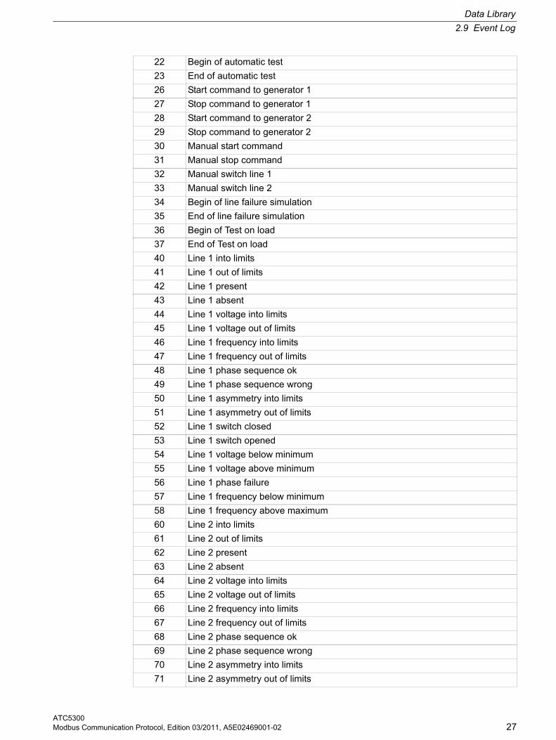
ATC5300Modbus Communication Protocol, Edition 03/2011, A5E02469001-02 27
22 Begin of automatic test
23 End of automatic test
26 Start command to generator 1
27 Stop command to generator 1
28 Start command to generator 2
29 Stop command to generator 2
30 Manual start command
31 Manual stop command
32 Manual switch line 1
33 Manual switch line 2
34 Begin of line failure simulation
35 End of line failure simulation
36 Begin of Test on load
37 End of Test on load
40 Line 1 into limits
41 Line 1 out of limits
42 Line 1 present
43 Line 1 absent
44 Line 1 voltage into limits
45 Line 1 voltage out of limits
46 Line 1 frequency into limits
47 Line 1 frequency out of limits
48 Line 1 phase sequence ok
49 Line 1 phase sequence wrong
50 Line 1 asymmetry into limits
51 Line 1 asymmetry out of limits
52 Line 1 switch closed
53 Line 1 switch opened
54 Line 1 voltage below minimum
55 Line 1 voltage above minimum
56 Line 1 phase failure
57 Line 1 frequency below minimum
58 Line 1 frequency above maximum
60 Line 2 into limits
61 Line 2 out of limits
62 Line 2 present
63 Line 2 absent
64 Line 2 voltage into limits
65 Line 2 voltage out of limits
66 Line 2 frequency into limits
67 Line 2 frequency out of limits
68 Line 2 phase sequence ok
69 Line 2 phase sequence wrong
70 Line 2 asymmetry into limits
71 Line 2 asymmetry out of limits
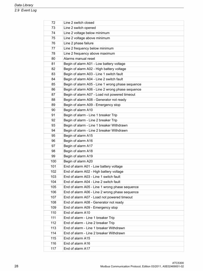
Data Library
2.9 Event Log
ATC530028 Modbus Communication Protocol, Edition 03/2011, A5E02469001-02
72 Line 2 switch closed
73 Line 2 switch opened
74 Line 2 voltage below minimum
75 Line 2 voltage above minimum
76 Line 2 phase failure
77 Line 2 frequency below minimum
78 Line 2 frequency above maximum
80 Alarms manual reset
81 Begin of alarm A01 - Low battery voltage
82 Begin of alarm A02 - High battery voltage
83 Begin of alarm A03 - Line 1 switch fault
84 Begin of alarm A04 - Line 2 switch fault
85 Begin of alarm A05 - Line 1 wrong phase sequence
86 Begin of alarm A06 - Line 2 wrong phase sequence
87 Begin of alarm A07 - Load not powered timeout
88 Begin of alarm A08 - Generator not ready
89 Begin of alarm A09 - Emergency stop
90 Begin of alarm A10
91 Begin of alarm - Line 1 breaker Trip
92 Begin of alarm - Line 2 breaker Trip
93 Begin of alarm - Line 1 breaker Withdrawn
94 Begin of alarm - Line 2 breaker Withdrawn
95 Begin of alarm A15
96 Begin of alarm A16
97 Begin of alarm A17
98 Begin of alarm A18
99 Begin of alarm A19
100 Begin of alarm A20
101 End of alarm A01 - Low battery voltage
102 End of alarm A02 - High battery voltage
103 End of alarm A03 - Line 1 switch fault
104 End of alarm A04 - Line 2 switch fault
105 End of alarm A05 - Line 1 wrong phase sequence
106 End of alarm A06 - Line 2 wrong phase sequence
107 End of alarm A07 - Load not powered timeout
108 End of alarm A08 - Generator not ready
109 End of alarm A09 - Emergency stop
110 End of alarm A10
111 End of alarm - Line 1 breaker Trip
112 End of alarm - Line 2 breaker Trip
113 End of alarm - Line 1 breaker Withdrawn
114 End of alarm - Line 2 breaker Withdrawn
115 End of alarm A15
116 End of alarm A16
117 End of alarm A17
Data Library
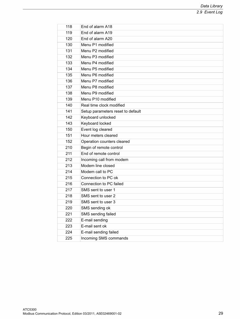
2.9 Event Log
ATC5300Modbus Communication Protocol, Edition 03/2011, A5E02469001-02 29
118 End of alarm A18
119 End of alarm A19
120 End of alarm A20
130 Menu P1 modified
131 Menu P2 modified
132 Menu P3 modified
133 Menu P4 modified
134 Menu P5 modified
135 Menu P6 modified
136 Menu P7 modified
137 Menu P8 modified
138 Menu P9 modified
139 Menu P10 modified
140 Real time clock modified
141 Setup parameters reset to default
142 Keyboard unlocked
143 Keyboard locked
150 Event log cleared
151 Hour meters cleared
152 Operation counters cleared
210 Begin of remote control
211 End of remote control
212 Incoming call from modem
213 Modem line closed
214 Modem call to PC
215 Connection to PC ok
216 Connection to PC failed
217 SMS sent to user 1
218 SMS sent to user 2
219 SMS sent to user 3
220 SMS sending ok
221 SMS sending failed
222 E-mail sending
223 E-mail sent ok
224 E-mail sending failed
225 Incoming SMS commands
Data Library
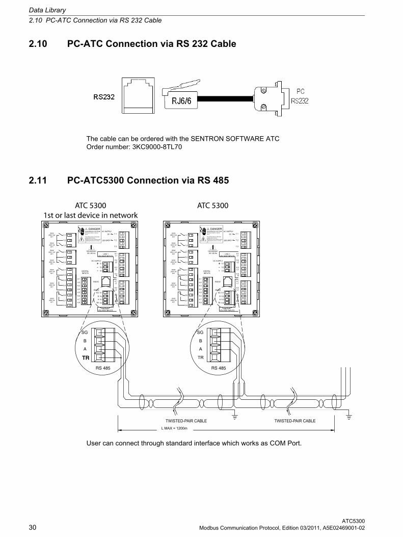
2.10 PC-ATC Connection via RS 232 Cable
ATC530030 Modbus Communication Protocol, Edition 03/2011, A5E02469001-02
2.10 PC-ATC Connection via RS 232 Cable
The cable can be ordered with the SENTRON SOFTWARE ATC Order number: 3KC9000-8TL70
2.11 PC-ATC5300 Connection via RS 485
User can connect through standard interface which works as COM Port.
VOLTAGE INPUTSLINE 2
VOLTAGE INPUTSLINE 2
LINE 1VOLTAGE INPUTS VOLTAGE INPUTS
LINE 1
AC SUPPLY AC SUPPLY
TR
RS 485
SG
B
A
TR
RS 485
SG
B
A
TWISTED-PAIR CABLE TWISTED-PAIR CABLE
ATC 53001st or last device in network
ATC 5300
INPUTSDIGITAL
3.3
250V 5A
250V 5AAC1
B300
AC1
B300
3.6
3.8
3.7
3.5
3.4
4.4
4.2
4.3
4.6
4.5
4.7
4.8
250V 5A
250V 12A
250V 12A
250V 5A
250V 5A
2.1
AC1
B300
B300
AC1
AC1
3.1
3.2
2.2
2.3
B300
AC1
B300
B300
AC1
1.3
1.2
1.1
4.19.1
RS485
TR 6.4
A 6.3
B 6.2
SG 6.1
RS232
9.3
9.4N
L3
9.2L2
L1
220-240V
0V
+DC SUPPLY
-- 5.3
5.2
5.1
8.4N
L38.3
8.2L2
L18.1
7.3
7.2
7.1
3.2
3.7250V 5AAC1
3.8
B300
3.6
3.5
B300
AC1250V 5A
3.3
3.4
2.3250V 5A
B300
AC1250V 5A
AC1
3.1
B300
B300
AC1250V 12A
2.2
2.1
1.1250V 12A
B300250V 5A
AC1
AC1
1.3
1.2
B300
N8.4
4.8 TR 6.4
4.6
4.7
4.5
4.4
4.2
4.3
4.1
RS485
B 6.2
A 6.3
SG 6.1
RS232
9.4N
9.2
9.3L3
L2
9.1L1
220-240V
DIGITALINPUTS
+DC SUPPLY
5.2-- 5.3
5.1L2
8.3L3
L1
8.2
8.1
7.3
7.2
0V 7.1
100-690VAC50 / 60 Hz 50 / 60 Hz
100-690VAC
L MAX = 1200m
HAZARDOUS VOLTAGEWill cause death or seriousinjury.
Turn off and lock out all powersupplying this device.Replace all covers before powersupplying this device is turnedon.
DANGERHAZARDOUS VOLTAGEWill cause death or seriousinjury.
Turn off and lock out all powersupplying this device.Replace all covers before powersupplying this device is turnedon.
DANGER