ATC 900 – CENTAUR – MONTY 8600 – VULCAN PRO · 1 CTC-CEN Service Manual 04-13 Rev.D ATC 900...
112
CTC-CEN Service Manual 04-13 Rev.D 1 ATC 900 – CENTAUR – MONTY 8600 – VULCAN PRO SERVICE MANUAL DO NOT COPY NOR DISTRIBUTE No part of this document may be photocopied, reproduced, or translated without prior written consent of Snap-on
Transcript of ATC 900 – CENTAUR – MONTY 8600 – VULCAN PRO · 1 CTC-CEN Service Manual 04-13 Rev.D ATC 900...

CTC-CEN Service Manual 04-13 Rev.D 1
ATC 900 – CENTAUR – MONTY 8600 – VULCAN PRO
SERVICE MANUAL
DO NOT COPY NOR DISTRIBUTE
No part of this document may be photocopied, reproduced, or translated without prior written consent of Snap-on

CTC-CEN Service Manual 04-13 Rev.D 2
B L A N K P A G E

CTC-CEN Service Manual 04-13 Rev.D 3
TABLE OF CONTENTS
CHAPTER 1 INTRODUCTION Pag. 5 1.1 General Pag. 5
CHAPTER 2 TOOLS AND SAFETY Pag. 5 2.1 Tools and special tools required Pag. 5 2.2 Important safety instructions Pag. 6 2.3 Electrical safety precautions Pag. 6
CHAPTER 3 ELECTRIC, PNEUMATIC AND HYDRAULIC DIAGRAMS Pag. 6 3.1 Electric diagram Pag. 7 3.2 Pneumatic diagram Pag. 8 CHAPTER 4 AC/DC POWER DISTRIBUTION Pag. 9 4.1 Lockout and/or tagout system procedure Pag. 9 4.2 Electrical requirements Pag. 9 4.3 AC Theoy of operation Pag. 9 4.4 DC Theory of operation Pag. 11 CHAPTER 5 ELECTRIC SECTION Pag. 13 5.1 Power supply cable and plug: check and replacement Pag. 13 5.2 Main rotary switch Q2 # 2-15359A: check and replacement Pag. 14 5.3 Centerpost motor M3 cable: check and replacement Pag. 15 5.4 Centerpost motor M3 # 2-49166A and belt # 8-06831A: check and replacement Pag. 16 5.5 Lower bead breaker arm actuator M1 # EAA0377G02A: check and replacement Pag. 17 5.6 Transformer T3 # 7-02702A: check and replacement Pag. 19 5.7 Centerpost switch S1 # 2-15259A: check and replacement Pag. 20 CHAPTER 6 ELECTRONIC SECTION Pag. 24 6.1 Inverter T1 # EAA0358G49A: check and replacement Pag. 24 6.2 Inverter T1 # EAA0358G49A: Firmware update Pag. 25 6.3 CPU board A1: check and replacement Pag. 28 6.4 Bead breaker arms potentiometer B1 and B2 # EAA0377G07A: check and replacement Pag. 28 6.5 Procedure to adjust bead breaker disks alignment Pag. 32 6.6 Bead breaker arms potentiometers calibration Rev.C Pag. 33 CHAPTER 7 PNEUMATIC SECTION Pag. 38 7.1 Pneumatic function Pag. 38 7.2 Air filter – lubricator assy # EAA0350G85A: check and replacement Pag. 39 7.3 Opening arm cylinder # EAA0350G44A: check and replacement Pag. 40 7.4 Valve control opening arm cylinder # EAA0356G96A:check and replacement Pag. 41 7.5 Vertical blocking cylinder # EAA0344G32A: check and replacement Pag. 42 7.6 Horizontal blocking cylinder # EAA0344G33A: check and replacement Pag. 44 7.7 Vertical rod lift cylinder # EAA0363G79A: check and replacement Pag. 45 7.8 Valve # EAA0338G09A: check and replacement Pag. 45 7.9 Automatic tool cylinder # EAA0363G81A: check and replacement Pag. 47 7.10 Automatic tool cylinder valve # EAA0328G73A: check and replacement Pag. 48 7.11 Bead breaker cylinders # EAA0363G62A / EAA0351G77A: check and replacement Pag. 49 7.12 Bead breaker cylinders and discs valves: # EAA0350G58A / EAA0377G25A: check and replacement Pag. 51 7.13 Bead breaker arms blocking cylinder # EAA0344G48A: check and replacement Pag. 52 7.14 Bead breaker arms valve blocking # EAA0377G26A: check and replacement Pag. 55 7.15 Wheel lift cylinder # EAA0344G93A: check and replacement Pag. 56 7.16 Wheel lift valve # EAA0349G00A: check and replacement Pag. 57 7.17 MH cylinder # EAA0345G61A: check and replacement Pag. 59 7.18 MH cylinder control valve # EAA0328G73A: check and replacement Pag. 60 7.19 Bead inflating valve # EAA0329G75A: check and replacement Pag. 61 7.20 Bead blaster valve # 1-29581A and air tank: check and replacement Pag. 62 7.21 Air control# EAA0350G54: check and replacement Pag. 62

CTC-CEN Service Manual 04-13 Rev.D 4
CHAPTER 8 MECHNICAL SECTION Pag. 64 8.0 Mechanical section Pag. 64 8.1 Opening arm bushings # 1-10065A check and replacement Pag. 64 8.1.1 Opening arm bushings # 1-10065A check and adjustment Pag. 68 8.2 Automatic tool # EAA0356G25A: check, replacement and adjustment Pag. 69 8.3 Horizontal arm rollers: check and adjustment Pag. 74 8.4 Gear box # EAA0347G76A: check and replacement Pag. 74 8.5 Bead breaker discs # EAM0065G63A: Check and replacement Pag. 75 8.6 Bead breaker discs # EAM0065G63A: Check and replacement Pag. 76 8.7 Bead breaker discs bearing # 1-06963A: Check and replacement Pag. 77 8.8 Bead breaker discs inclination adjustment. Pag. 78 8.9 Bead breaker discs clearance: Check and adjustment Pag. 79 8.10 Bead breaker carriage: Check and adjustment Pag. 81 8.11 Lead screw nut # EAM0076G10A: Check and adjustment Pag. 81 CHAPTER 9 TROUBLE SHOOTING Pag. 82 CHAPTER 10 SERVICE BULLETINS Pag. 86

CTC-CEN Service Manual 04-13 Rev.D 5
CHAPTER 1 INTRODUCTION
1.1 GENERAL This Service Manual describes maintenance, check and repair operations of the Dual bead breaker and Automatic tool tire changer platform under Hofmann, John Bean and Boxer brands and is for use of qualified and trained personnel only. Keep this manual constantly updated, by adding Service Bulletins related to the tire changers.
IMPORTANT! The identification data of each machine are printed on a adhesive label attached to the cabinet of the machines. The serial number is a sequence of figures standing for the manufacturing month and year the first four numbers, followed by the machine part number made of 7 numbers and finally the progressive serial number of the machine manufactured with this specific part number. In the sections dedicated to the check, replacement and adjustment of the components there will be reported some symbols as follows: : Total amount of working time required to check, replace and adjust the components: this time is
calculated considering the standard installation condition provided by the operator manual. : List of tools required to perform the work. : Information related to the possible failure/malfunction caused by the component
CHAPTER 2 TOOLS AND SAFETY
2.1 TOOLS AND SPECIAL TOOLS To repair and/or check these tire changer, the following standard tools are required:
Keys : 6mm to 30mm Tube type keys : 7mm to 17mm Allen keys : 2.5 mm to 12 mm Socket keys : 17mm to 24mm Allen socket keys : 8mm to 12mm Screw drivers : Flat bed and Phillips from 1 to 5 Multimeter : AC, DC, A, Ohm, pF Lotctite and mechanical extractor
Special tools that are required for specific tasks are:
Ring nut socket keys: There are 4 different keys: 10mm, 17mm, 20mm and 25mm. Use these keys to tight or loose the knees ring nuts.

CTC-CEN Service Manual 04-13 Rev.D 6
Electronic inclinometer:
Use the electronic level to adjust the bead breaker disc inclination
Kit Inverter firmware update # EAK0306G03A. Use this kit to update directly on site the firmware of the Snap On Inverters instead to replace it
2.2 MPORTANT SAFETY INSTRUCTIONS The units are CE or UL approved, but whenever using this equipment basic safety precautions should always be followed, including the following:
1. Read all instructions.
2. Do not operate equipment with a damaged power cord or if the equipment has been damaged until it has been examined by a qualified authorized service technician.
3. If an extension cord is used, a cord with a current rating equal to or more than that of the machine should be used. Cords rated for less current than the equipment may overheat. Care should be taken to arrange the cord so that it will not be tripped over or pulled.
4. Always unplug equipment from electrical outlet when not in use. Never use the cord to pull the plug from the outlet. Grasp plug and pull to disconnect.
5. To reduce the risk of fire, do not operate equipment in the vicinity of open containers of flammable liquids (gasoline).
6. Keep hair, loose fitting clothing, fingers and all parts of the body away from moving parts.
7. Adequate ventilation should be provided when working on operating internal combustion engines.
8. To reduce the risk of electric shock, do not use on wet surfaces or expose to rain.
9. Do not hammer on or hit any part of the control box and portable control.
10. Do not allow unauthorized personnel to operate the equipment.
11. Use only as described in this manual. Use only manufacturer’s recommended attachments.
12. Always securely lock the wheel before starting the operation.
13. ALWAYS WEAR SAFETY GLASSES. Everyday eyeglasses only have impact resistant lenses, they are NOT safety glasses.
14. Easy tire changer is for indoor use only.
2.3 ELECTRICAL SAFETY PRECAUTIONS Make sure the tire changer is unplugged before disconnecting any wires in preparation for replacing any electric mechanic components, cables or other items within the unit
CHAPTER 3 ELECTRIC, AND PNEUMATIC DIAGRAMS
CTC-CEN Service Manual 04-13 Rev.D 7
ELECTRIC DIAGRAM

CTC-CEN Service Manual 04-13 Rev.D 8
PNEUMATIC DIAGRAMS

CTC-CEN Service Manual 04-13 Rev.D 9
CHAPTER 4 AC/DC POWER DISTRIBUTION
4.1 LOCKOUT AND/OR TAGOUT SYSTEM PROCEDURE 1. Notify all affected employees that a lockout or tagout system is going to be utilized and why. The authorized employee should know the electrical power the machine uses and it’s hazards.
2. If the machine or equipment is running, shut it down by the normal stopping procedure (depress the stop button, open toggle switch, etc.).
3. Use appropriate devices to isolate the equipment from the power source(s). Stored energy (such as that in springs, elevated machine members, rotating flywheels, hydraulic systems, and air gas, steam or water pressure, etc.) must be dissipated or restrained by methods such as repositioning, blocking, bleeding down, etc.
4. Lockout and/or tagout the energy isolating devices with individual lock(s) or tag(s).
5. After ensuring that no personnel are exposed, and as a check on having disconnected the energy sources, operate the push button or other normal operating controls to make certain the equipment will not operate. CAUTION: RETURN OPERATING CONTROL(S) TO “NEUTRAL” OR “OFF” POSITION AFTER THE TEST [DE-ENERGIZED STATE].
6. The equipment is now locked out or tagged out.
4.2 ELECTRICAL REQUIREMENTS NOTE: ANY ELECTRICAL WIRING MUST BE PERFORMED BY LICENSED PERSONNEL. ALL SERVICE MUST BE PERFORMED BY AN AUTHORIZED SERVICE TECHNICIAN. Check on the plate of the machine that the electrical specifications of the power source are the same as that of the machine.
NOTE: ANY ELECTRICAL OUTLET INSTALLATION MUST BE VERIFIED BY A LICENSED ELECTRICIAN BEFORE CONNECTING THE TIRE CHANGER.
NOTE: ENSURE THAT THE OUTLET HAS AN AUTOMATIC GROUND FAULT CIRCUIT BREAKER WITH A DIFFERENTIAL CIRCUIT SET AT 30 MA.
4.3 AC THEORY OF OPERATIONS
Always use the “One Hand Rule” when working with AC voltages by keeping one hand in your pocket or behind your back. Before removing wires from the tire changer, always verify that the unit is “OFF”. Turn off the Main Power Switch on the back and unplug the AC power cord from the AC outlet.
AC DISTRIBUTION All Easy platform tire changers are equipped by one 230 VAC three phase turntable motor. The voltage at which the machine is wired is printed on the serial number plate and on a tag at the end of the power cord.
The power cord has 3 wires: N = Neutral L1 = Phases PE (yellow/green) = Ground
The machines can work at 50 or 60 Hertz. The 230 (+/-10%) AC voltage comes in through a “ON/OFF” Power Switch placed on the electronic box cover and immediately is sent via to an anti disturb filter to the Inverter and to the transformer.

CTC-CEN Service Manual 04-13 Rev.D 10
TRANSFORMER T3 It transforms the 230VAC in 18VAC to supply the CPU board A1 through the connector X2. INVERTER T1 It supplies 230/3 to the turntable motor M3 and change the motor rotational speed from 50 to 100Hz.
CENTERPOST SWITCH S1 The switch forward the rotational and speed input to the inverter T1 for the motor M3.

CTC-CEN Service Manual 04-13 Rev.D 11
CENTERPOST MOTOR M3 It is 1,5 Hp, 3 phase single speed motor and it is supplied by the inverter T1.
4.4 DC THEORY OF OPERATIONS PROCESSOR BOARD A1 The processor board A1 (CPU) is placed inside of the electronic box and it is directly supplied at 18 VAC by the transformer T3. A fuse avoid damaging in case of overcurrent from the transformer. The CPU board manages all input from / to the bead breaker arms potentiometers, the lower bead breaker arm actuator and the laser pointer. BEAD BREAKER ARMS POTENZIOMETERS B1 AND B2 The bead breaker arm potentiometers are 3 turns type – 5K first batch, 10K the present one, and they are supplied at 5 VDC by the CPU board. They control the position of the bead breaker arms in order to allow a constant alignment of the bead breaker discs. LOWER BEAD BREAKER ARM ACTUATOR M2 The lower bead breaker arm actuator M1 is controlled by the CPU board through the potentiometers. It supplied at 24VDC and allows the forward / backward lower bead breaker arm sliding as soon as the upper one is moved by the operator.

CTC-CEN Service Manual 04-13 Rev.D 12
LASER POINTER The laser pointer is directly supplied by the CPU board through the connectors X4 and X5. It is used to make an easier positioning of the tool on the rim edge.
WARNING! LASER RADIATION
CLASS 2 LASER PRODUCT 1mW 650 nm CW
DO NOT STARE INTO BEAM IEC 60825-1:2007

CTC-CEN Service Manual 04-13 Rev.D
13
CHAPTER 5 ELECTRIC SECTION
WARNING! BEFORE APPROACHING THE ELECTRIC PARTS OF THE MACHINE,
DISCONNECT THE MACHINE FROM ELECTRIC SUPPLY
Very often electric failures are only caused by loosened wires or connectors not well fitted. Therefore it is VERY IMPORTANT BEFORE STARTING WITH ANY CONTROL AND/OR REPLACEMENT VERIFY IF ALL WIRES AND CONNECTORS ARE WELL FITTED.
5.1 POWER SUPPLY CABLE AND PLUG: CHECK AND REPLACEMENT
: 1h : Allen keys of 3 and 5mm, small and medium screwdriver, medium cross screwdriver, faston pliers, scissors,
pliers, multimeter. : Defective power supply cable and plug may cause the following malfunction: 1. Turning the switch on, the electric functions of machine do not work.
TO CHECK THE CABLE:
Disconnect power supply. Remove the plug form the wall. Loosen the screw to remove switch knob. Remove the disc acting with a screwdriver on the side tabs Loose the screws and remove the frame switch. Take the switch out from the inverter box.

CTC-CEN Service Manual 04-13 Rev.D
14
Check wires continuity from power supply plug to main switch wires terminals.
IMPORTANT! TO CHECK GROUND (YELLOW/GREEN) WIRE, DISCONNECT THE WIRE END FROM THE TERMINAL BLOCK. TO REPLACE THE CABLE:
Disconnect the power supply wires from the plug and switch teminals. Disconnect the ground wire from terminal block. Release cable strain relief from the inverter box. Remove plug from cord and take the defective cable away. Insert the new cable through the strain relief.
IMPORTANT! USE ONLY APPROVED CABLES, PLUGS. GROUND WIRE MUST BE LONGER THAN THE OTHER ONES.
Fix new faston on inside cable ends and connect them to the switch terminals and to the plug. Fix the main switch to the electronic box. Install the disc. Mount again the switch knob and cover of the screw. Connect the ground wire to ground terminal block. Install plug. Tighten strain relief FIRMLY. Plug the machine to the wall. Check if the machine works fine. Fix the inverter box again to the cabinet.
5.2 MAIN ROTARY SWITCH Q1 # 2-15359A: CHECK AND REPLACEMENT : 0,5h : Allen keys of 3 and 5mm, small and medium screwdriver, medium cross screwdriver, faston pliers, scissors,
pliers, multimeter : Defective main switch may cause the following malfunction: 1. Turning the switch on the machine does not run at all. 2. Turning the machine on the building main switch shuts off.
TO CHECK THE SWITCH:
Disconnect power supply. Remove the switch from the electronic box 5.1 Disconnect all wires from the main switch and remove it with a
screwdriver. Turn switch to “Off”. Check that there is no continuity (=infinity)
between any terminals 1,2,3 and 4. Turn switch to “On”. Check that there is continuity between
terminals 1-2 and 3-4 (= 0 ~ 0,3) and discontinuity between terminals 1-3 and 1-4, as well as 2-3 and 2-4
If there is continuity the switch is in short circuit. It must be replaced.
CTC-CEN Service Manual 04-13 Rev.D
15
TO REPLACE THE SWITCH:
Check that the tabs for contacts on the new switch are correctly oriented. Connect wires ends FIRMLY to the new switch terminals as shown in the appropriate electric diagram (3.0). Mount the switch to the electronic box 5.1. Check if the machine works fine.
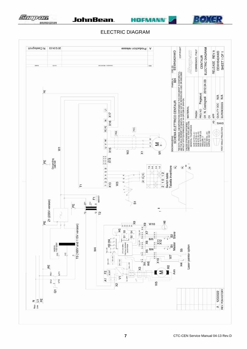
5.3 CENTERPOST MOTOR M3 CABLE: CHECK AND REPLACEMENT : 1h : Medium screwdrivers, medium cross screwdrivers, 7mm tube type wrench, 4mm allen key, pliers, multimeter : Defective chuck motor cable may cause the following malfunction: 1. Low rotational torque. 2. Noisy motor. 3. Motor damaging (burning). TO CHECK THE CABLE: Disconnect power supply from the wall. Open the electric box. Disconnect the wires white, brown and black from the Inverter. Remove the front motor protection to access to the centerpost motor Remove the motor terminals cover and disconnect all wires from
terminals. Select the multimeter in Ohm and check if there is continuity
between ends of each wire.
CTC-CEN Service Manual 04-13 Rev.D
16
TO REPLACE THE CABLE:
Release cable strain relief on the electric box and on the motor. Take the wrong cable away. Insert the new cable through the strain relief.
IMPORTANT! USE ONLY APPROVED CABLE. GROUND WIRE MUST BE LITTLE LONGER THAN THE OTHER ONES TO ALLOW THE GROUND IN CASE OF PHASE CABLE BREAKAGE. NOTE: Before connecting the wires ends, tighten all terminals nuts on the motor.
Fix new fastons to the cable ends. Connect the wires to the motor and inverter terminals. Mount the motor terminal cover and the electronic box cover.
IMPORTANT: WHEN REMOUNTING THE MOTOR TERMINALS COVER BE CAREFUL NOT TO CRUSH WIRES.
Plug the machine to wall. Turn the machine on and check if it works fine. Mount the front motor cover.
5.4 CENTERPOST MOTOR M3 # 2-49166A AND BELT # 8-06831A: CHECK AND REPLACEMENT : 1h : End keys 13,17mm, medium cross screwdriver, 7mm tube type wrenches, 3 and 4mm allen key, multimeter,
loctite, extractor. : Defective centerpost motor may cause the following malfunction: 1. Motor is noisy. 2. Motor is burnt. 3. Low turntable torque.
TO CECK THE CENTERPOST MOTOR WHEN IT SHOWS LOW TORQUE OR IT IS NOISY:
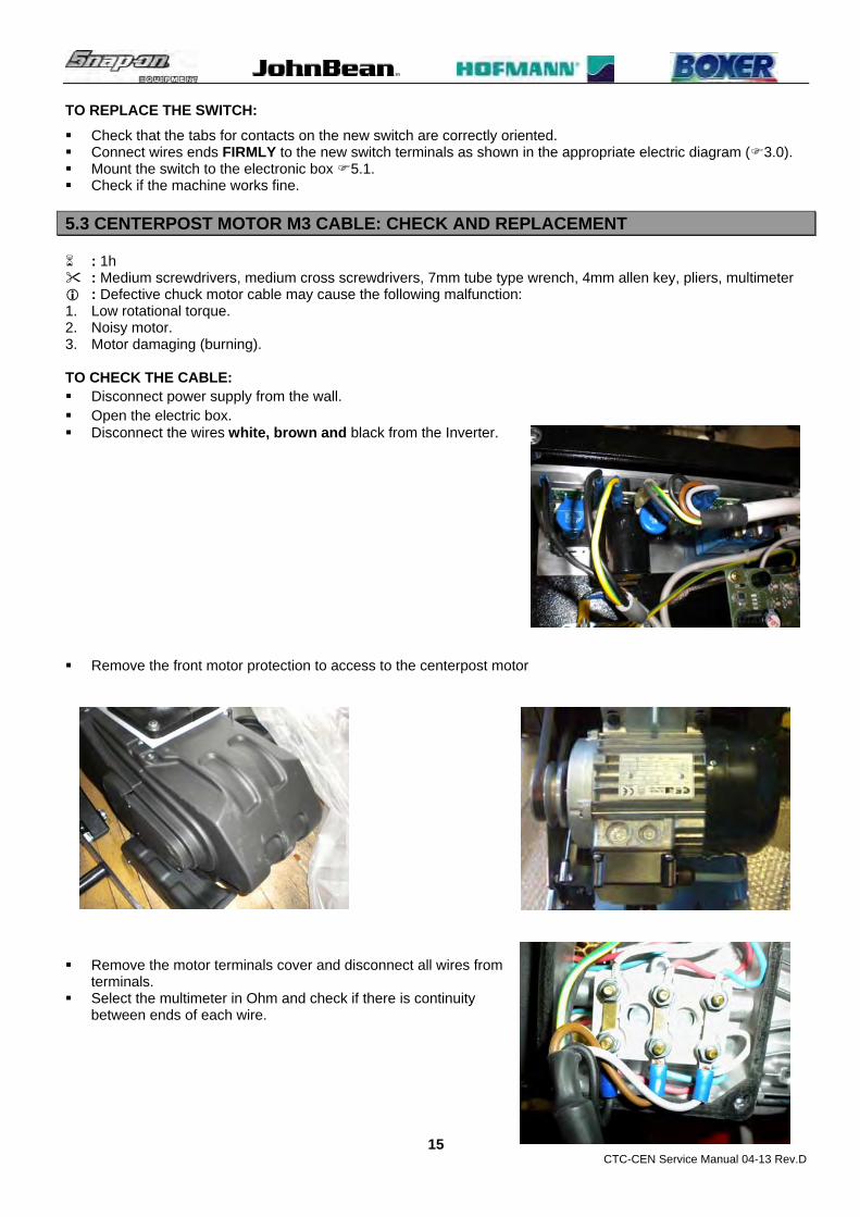
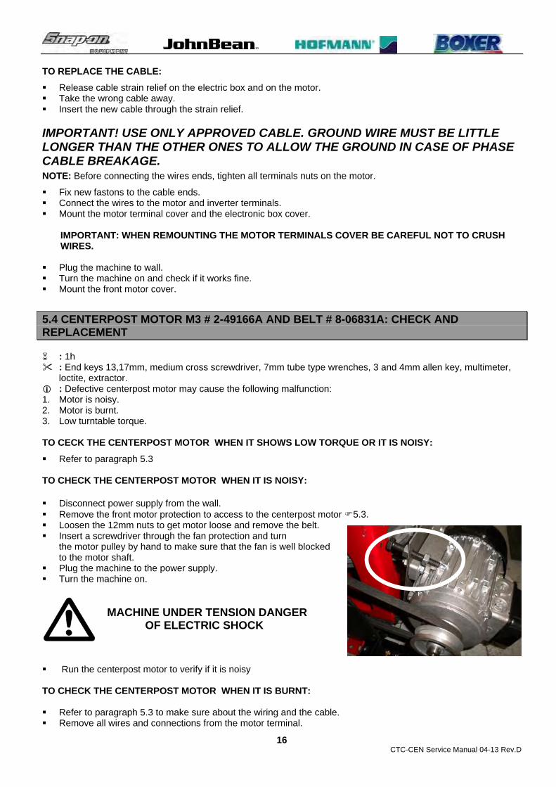
Refer to paragraph 5.3 TO CHECK THE CENTERPOST MOTOR WHEN IT IS NOISY: Disconnect power supply from the wall. Remove the front motor protection to access to the centerpost motor 5.3. Loosen the 12mm nuts to get motor loose and remove the belt. Insert a screwdriver through the fan protection and turn
the motor pulley by hand to make sure that the fan is well blocked to the motor shaft.
Plug the machine to the power supply. Turn the machine on. MACHINE UNDER TENSION DANGER OF ELECTRIC SHOCK
Run the centerpost motor to verify if it is noisy
TO CHECK THE CENTERPOST MOTOR WHEN IT IS BURNT: Refer to paragraph 5.3 to make sure about the wiring and the cable. Remove all wires and connections from the motor terminal.

CTC-CEN Service Manual 04-13 Rev.D
17
Select the multimeter in Ohm and check if there is continuity between all terminals of the motor. If there continuity the motor must be replaced.
TO REPLACE THE CENTERPOST MOTOR:
Remove the two bolts in the bottom to get the motor assembly free. Remove the pulley set screws. Remove the pulley by using an extractor tool. Remove the motor from its support. Take the new motor. Install the pulley by using rubber hammer. NOTE: The mounting of the new pulley must be done very carefully in order to avoid motor bearings damaging. Install the motor on its support. Install the motor assy on the machine and lock it firmly. Mount the belt. Adjust the belt tension Connect the wires FIRMLY to motor terminals following the
voltage at which the machine is supplied.
NOTE: Before connecting the wires ends, tighten all terminals nuts.
Plug the machine to the wall. Turn the machine on.
MACHINE UNDER TENSION DANGER OF ELECTRIC SHOCK Check the rotation way of the motor: If it is wrong reverse only two centerpost motor wires. Turn the machine off and unplug it from the wall. Mount the motor terminals cover.
IMPORTANT: WHEN REMOUNTING THE MOTOR TERMINALS COVER BE CAREFUL NOT TO CRUSH WIRES.
Mount all protections and covers. Turn the machine on again and check if it works fine again.
5.5 LOWER BEAD BREAKER ARM ACTUATOR M1 EAA0377G02A: CHECK AND REPLACEMENT : 1,5h : End keys 13, medium cross screwdriver, 4 and 5mm allen key, multimeter. : Defective actuator motor may cause the following malfunction: 1. The lower bead breaker arm does not move forward and backward. TO CHECK THE MOTOR: Before working on the actuator, make sure that the bead breaker arm is unlocked, cleaned and without any
scratching. Disconnect machine from power supply. Open the electric box. Disconnect the actuator plug from the connector X3 of the CPU board. Turn the machine on. MACHINE UNDER TENSION DANGER OF ELECTRIC SHOCK

CTC-CEN Service Manual 04-13 Rev.D
18
Take the Voltmeter and select it in VDC. Position the Voltmeter probes on the connector terminals X3
coming from the CPU board inside of electric box. Push the upper bead breaker arm by hand: whenever it will move
the multimeter display should show 24VDC. If the multimeter display will not show any change of value, the
CPU board must be replaced. TO REPLACE THE MOTOR: Turn the machine off. Remove the protection from the lower bead breaker arm. Make sure that the bead breaker arm is unlocked Disconnect the motor from the arm. Turn the worm screw handily to remove the actuator from the arm. Remove the cable from electric box. Remove the cable from the chain. Move the lower bead breaker arm all inward. Fix the actuator to arm. Insert the cable through the chain and connect it to the CPU
board. Turn the machine on.
CTC-CEN Service Manual 04-13 Rev.D
19
MACHINE UNDER TENSION DANGER OF ELECTRIC SHOCK
Push and pull the upper bead breaker arm by hand inward and
outward to make sure that actuator is running. At the same time use the 5mm allen key to adjust the alignment of the actuator to the bead breaker arm.
When the actuator will complete the arm stroke without any speed reduction, lock the counter nut.
Perform the bead breaker arms calibration. Turn off the machine. Install the actuator and the electric box protection. Turn the machine on and check if it works fine.
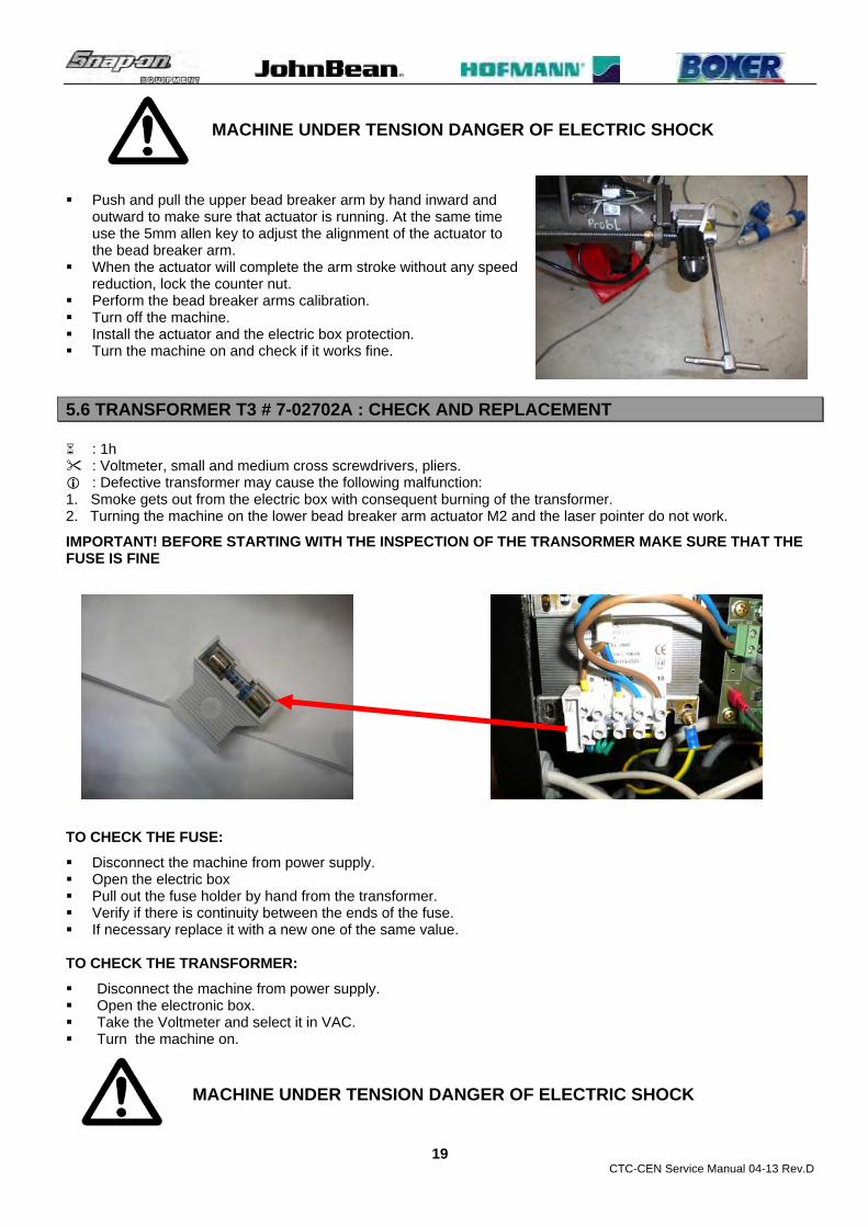
5.6 TRANSFORMER T3 # 7-02702A : CHECK AND REPLACEMENT : 1h : Voltmeter, small and medium cross screwdrivers, pliers. : Defective transformer may cause the following malfunction: 1. Smoke gets out from the electric box with consequent burning of the transformer. 2. Turning the machine on the lower bead breaker arm actuator M2 and the laser pointer do not work.
IMPORTANT! BEFORE STARTING WITH THE INSPECTION OF THE TRANSORMER MAKE SURE THAT THE FUSE IS FINE
TO CHECK THE FUSE:
Disconnect the machine from power supply. Open the electric box Pull out the fuse holder by hand from the transformer. Verify if there is continuity between the ends of the fuse. If necessary replace it with a new one of the same value. TO CHECK THE TRANSFORMER:
Disconnect the machine from power supply. Open the electronic box. Take the Voltmeter and select it in VAC. Turn the machine on. MACHINE UNDER TENSION DANGER OF ELECTRIC SHOCK
CTC-CEN Service Manual 04-13 Rev.D
20
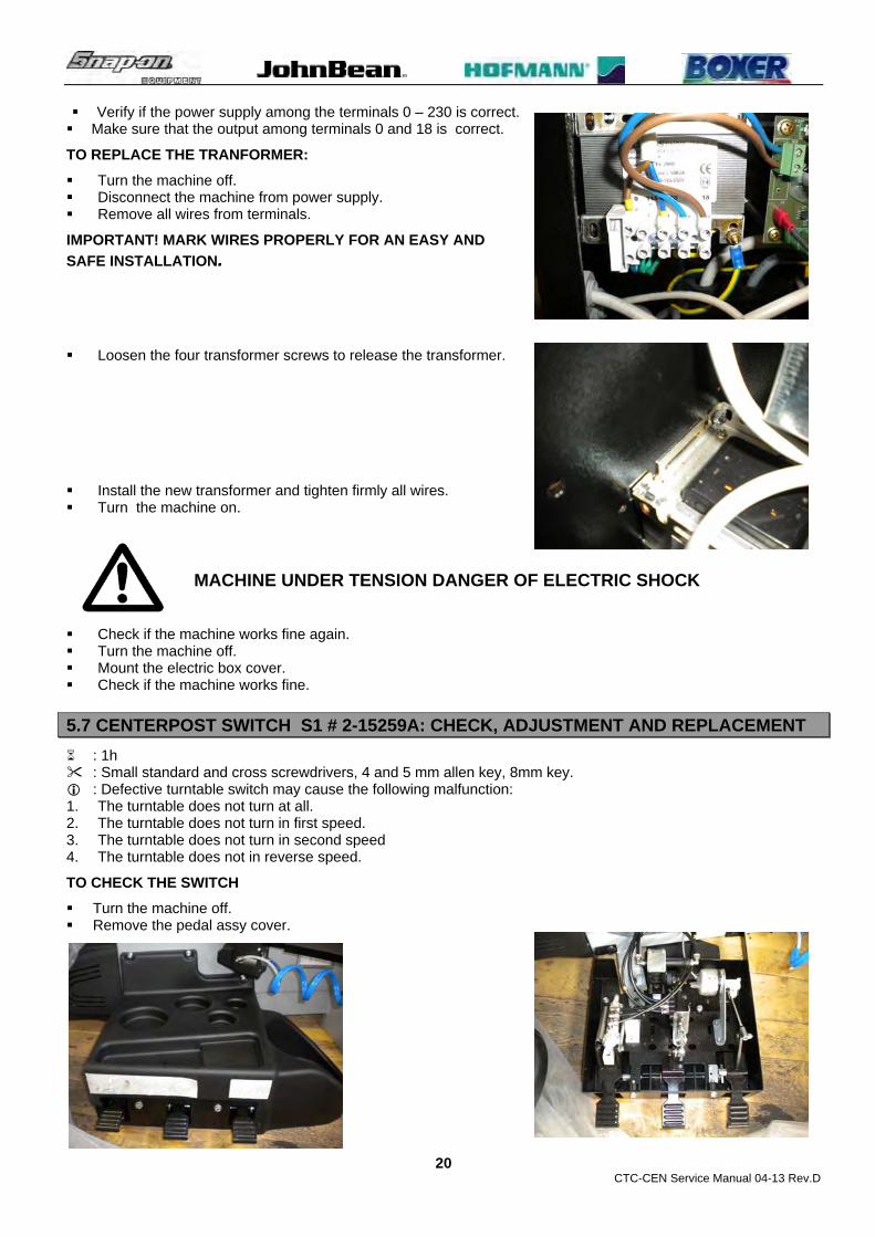
Verify if the power supply among the terminals 0 – 230 is correct. Make sure that the output among terminals 0 and 18 is correct.
TO REPLACE THE TRANFORMER:
Turn the machine off. Disconnect the machine from power supply. Remove all wires from terminals.
IMPORTANT! MARK WIRES PROPERLY FOR AN EASY AND
SAFE INSTALLATION.
Loosen the four transformer screws to release the transformer. Install the new transformer and tighten firmly all wires. Turn the machine on.
MACHINE UNDER TENSION DANGER OF ELECTRIC SHOCK Check if the machine works fine again. Turn the machine off. Mount the electric box cover. Check if the machine works fine.
5.7 CENTERPOST SWITCH S1 # 2-15259A: CHECK, ADJUSTMENT AND REPLACEMENT
: 1h : Small standard and cross screwdrivers, 4 and 5 mm allen key, 8mm key. : Defective turntable switch may cause the following malfunction: 1. The turntable does not turn at all. 2. The turntable does not turn in first speed. 3. The turntable does not turn in second speed 4. The turntable does not in reverse speed.
TO CHECK THE SWITCH
Turn the machine off. Remove the pedal assy cover.

CTC-CEN Service Manual 04-13 Rev.D
21
Make sure that the switch is mechanically in good condition. Press or push the pedal to make sure that the switch is properly adjusted: if not make a new adjustment Disconnect the wires from the switch terminals.
IMPORTANT! MARK WIRES PROPERLY FOR AN EASY AND SAFE INSTALLATION
Take a Voltmeter and select it in Ohm. In case the motor does not turn in first speed, position the Voltmeter probes on terminals 1 and 4 and press the
pedal to verify if there continuity. If not replace the switch.
In case the motor does not turn in second speed, position the Voltmeter probes on terminals 1 - 4 and 1-8 and press the pedal to verify if there continuity. If not replace the switch.
In case the motor does not turn in reversed speed, position the Voltmeter probes on terminals 1-8 and push up the pedal to verify if there continuity. If not replace the switch
TO ADJUST THE SWITCH:
Make sure that the bar is more or less in the middle of the switch lever button-hole when the switch is in rest position.
If it is not in the middle loosen the nut #1 and remove the bolts #2.

CTC-CEN Service Manual 04-13 Rev.D
22
Turn half of a turn the spacer #3 and check if it is in the correct position.
Press the pedal all way down and make sure that switch has already switched to the second step before the pedal has reached the end of stroke.
Push the pedal all way up and make sure that switch that the switch engages before the back side of the pedal touches the pedals support
TO REPLACE THE SWITCH:
Loosen the screw that hold the switch lever.
CTC-CEN Service Manual 04-13 Rev.D
23
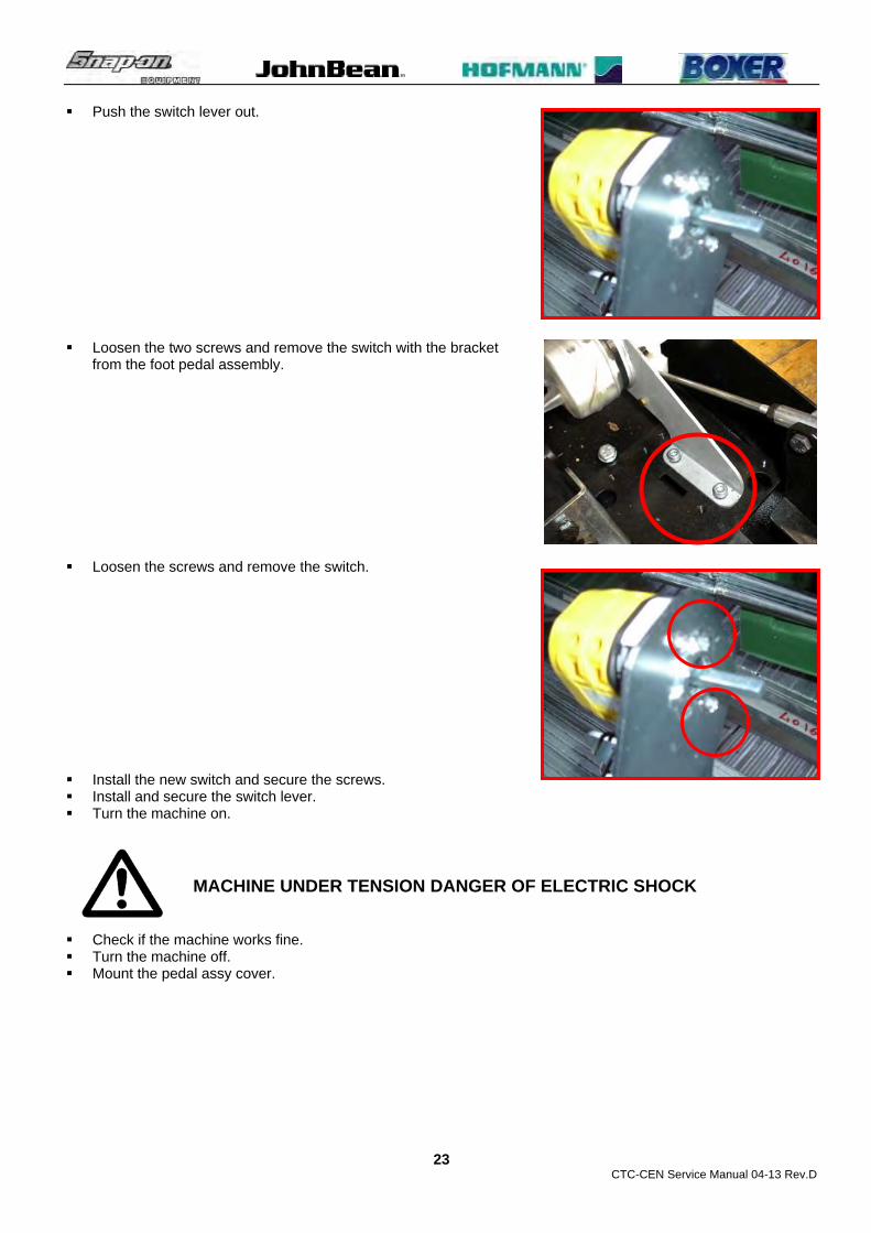
Push the switch lever out. Loosen the two screws and remove the switch with the bracket
from the foot pedal assembly. Loosen the screws and remove the switch.
Install the new switch and secure the screws. Install and secure the switch lever. Turn the machine on.
MACHINE UNDER TENSION DANGER OF ELECTRIC SHOCK Check if the machine works fine. Turn the machine off. Mount the pedal assy cover.

CTC-CEN Service Manual 04-13 Rev.D
24
CHAPTER 6
ELECTRONIC SECTION
WARNING! BEFORE APPROACHING THE ELECTRONIC PARTS OF THE MACHINE,
DISCONNECT THE MACHINE FROM POWER SUPPLY.
6.1 INVERTER T1 # EAA0358G49A: CHECK AND REPLACEMENT : 1h : Voltmeter, small and medium cross screwdrivers, 8mm tube type key, pliers. : Defective inverter may cause the following malfunction: 1. Centerpost motor does not turn at all. 2. Centerpost motor turns in slow speed only 3. Centerpost motor turns in high speed only. 4. Centerpost motor turns in reverse direction only. 5. Centerpost does not turn in second speed. 6. The shut off switch of the tire shop shuts off. TO CHECK THE INVERTER:
Turn the machine on. Press the rotational pedal: if the motor does not run or if the tire shop shut off switch shuts off, the inverter must
be replaced. IMPORTANT! BEFORE REPLACING THE EMC INVERTER MAKE SURE THAT THE TURNTABLE MOTOR AND WIRE ARE FINE. TO REPLACE THE INVERTER:
Turn the machine off. Open the electric box. Disconnect the wires and the connectors from the inverter terminals
marking the position. Remove the two screws and take the inverter out. Mount the new inverter. Connect all wires to the terminals following the correct order. Close the electric box. Check if the machine works fine.

CTC-CEN Service Manual 04-13 Rev.D
25
6.2 INVERTER T1# EAA0358G49A: FIRMWARE UPDATE
: 2h : Medium cross screwdriver, Note book PC.
Inverter firmware update kit WARNING: The PC used to program the inverter and the inverter can’t be connected both to the mains, follow the admitted connection below.

CTC-CEN Service Manual 04-13 Rev.D
26
Software installation. a) Use the CD named PIClit Starter Kit b) Open the directory D:\Install\PICkit 2 and start Setup program. At the end of the install program, a icon will be on the desktop. The last revision of firmware (hex file) will be sent by e-mail.

CTC-CEN Service Manual 04-13 Rev.D
27
Programmer connection a) Connect the programmer to the USB port, and the programming cable as shown below. WARNING: the blue connection must be inserted in the porogrammer connection marked with A small triangle.
b) Connect the programming cable to the inverter programming port.

CTC-CEN Service Manual 04-13 Rev.D
28
Update firmware Start programming software with icon.
b) With File -> Import menu, load hex file as shown below.
b) Push the Write button to start the update procedure. At the end a success message is shown.

CTC-CEN Service Manual 04-13 Rev.D
29
6.3 CPU BOARD A1 # EAP0275G50A: CHECK AND REPLACEMENT
: 1h : Medium cross screwdriver, 5mm allen key, 7mm key, multimeter. : Defective processor board may cause the following malfunction: 1. Turning the machine on, the lower bead breaker will not move, the laser pointer will not work. IMPORTANT! BEFORE STARTING WITH ANY REPLACEMET CHECK CAREFULLY IF ALL WIRES AND CONNECTORS ARE WELL FITTED AND IF THE FUSE IS FINE. TO CHECK THE PROCESSOR BOARD A1: Turn the machine off. Open the electric box. Check the fuse, wirings and connectors. Turn the machine on MACHINE UNDER TENSION DANGER OF ELECTRIC SHOCK Take a multimeter and make sure that the board is properly
supplied by the transformer trough connector X2 (red). Make sure that there is power output from connector X3 (blue). TO REPLACE THE PROCESSOR BOARD A1: Turn off the machine. Disconnect all connectors and wires. IMPORTANT! DO NOT REMOVE THE CONNECTORS PULLING FROM THE WIRES. PULL FROM THE CONNECTOR ONLY. Remove the 4 screws with the screwdriver. IMPORTANT! MARK CONNECTORS PROPERLY FOR AN EASY AND SAFE INSTALLATION
Install the new board. Install all connectors and wires. Mount the electric box cover. Turn the machine on. Perform the bead breaker arms calibration.
6.4 BEAD BREAKER ARMS POTENTIOMETERS B1 AND B2 # EAA0377G07A: CHECK AND REPLACEMENT
: 1h each one. : 4 and 5mm Allen Key, 10 and 13mm end key, medium standard screwdriver, Multimeter. : Defective potentiometer may cause the following malfunction: 1. The bead breaker arms are not synchronized. 2. The lower bead breaker arm will not move.
TO CHECK THE 3 TURNS SLAVE POTENTIOMETER:
Turn the machine off. Remove the electric cover. Remove the lower potentiometer protection.

CTC-CEN Service Manual 04-13 Rev.D
30
Disconnect the actuator M2 following par.5.5 Proceed following the next steps. At the end adjust the actuator following par. 5.5. Perform the bead breaker arm calibration.
TO CHECK THE 3 TURNS MASTER POTENTIOMETER:
Turn the machine off. Remove the electric cover. Position the upper bead breaker arm to the inward end of stroke. Turn the machine on. MACHINE UNDER TENSION DANGER OF ELECTRIC SHOCK Take the multimeter and select it in VDC. Position its terminals on the potentiometer wires green and white. Move the arm until end of stroke: the multimeter must display a value from -4.6 to -0.121 on 5K potentiometer
and -9.6 to -0.2 on 10K one.
CTC-CEN Service Manual 04-13 Rev.D
31
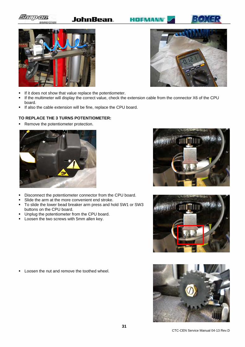
If it does not show that value replace the potentiometer. If the multimeter will display the correct value, check the extension cable from the connector X6 of the CPU
board. If also the cable extension will be fine, replace the CPU board.
TO REPLACE THE 3 TURNS POTENTIOMETER:
Remove the potentiometer protection.
Disconnect the potentiometer connector from the CPU board. Slide the arm at the more convenient end stroke. To slide the lower bead breaker arm press and hold SW1 or SW3
buttons on the CPU board. Unplug the potentiometer from the CPU board. Loosen the two screws with 5mm allen key. Loosen the nut and remove the toothed wheel.

CTC-CEN Service Manual 04-13 Rev.D
32
Remove the threaded toothed wheel bushing.
Remove the potentiometer from its holder. Install the new potentiometer on its holder. Mount the threaded toothed wheel bushing. Mount the toothed wheel and lock it with the nut. Turn the potentiometer manually at the end of its stroke and then make sure to turn the wheel back of a quarter
of a turn.
IMPORTANT! MAKE SURE ABOUT THE POTENTIOMETER ROTATION DIRECTION BECAUSE A WRONG END STROKE DIRECTION WILL CAUSE THE BREAKAGE OF THE POTETIOMETER WHEN WILL ROTATE.
Mount the potentiometer assy to the armr. Mark the toothed wheel. Slide the bead breaker arm all way in or out checking that the number of revolution made by wheel are 2 and
making sure that the potentiometer will not be at the end of the stroke
6.5 PROCEDURE TO ADJUST BEAD BREAKER DISKS ALIGNMENT In case of complaints related to bead breaker disks misalignment out of the maximum tolerance allowed, 1mm/0,04”, we would like to inform you that it is now available the following procedure to correct the output analog value of the potentiometer/s improving the bead breaker disks alignment accuracy.
PROCEDURE:
1. Fix to the multimeter terminals two small crocodiles style ones. 2. Remove the cover from the bead breaker arm potentiometer. 3. Select the multimeter in Vdc.

CTC-CEN Service Manual 04-13 Rev.D
33
4. Position the red crocodile to the green wire and the black one on the white wire of the potentiometer.
5. Turn the machine on. 6. Move the bead breaker arms to maximum error point.
7. Read the value displayed on the multimeter. 8. Unlock the potentiometer counter nut. 9. Turn the potentiometer with a flat screwdriver
subtracting 0,020 Vdc from the value displayed.
10. Lock the counter nut again. 11. Calibrate the machine. 12. Check if the arms are better aligned. 13. Turn the machine off. 14. Install the potentiometer cover again.
6.6 BEAD BREAKER ARMS CALIBRATION SW 1.0.3 / 1.0.4 : 30’. : 5mm Allen. The bead breaker arm potentiometers calibration can be performed by pressing the following button placed on the CPU board inside of the electric box. SW1 Inward lower bead breaker arm motion (enable during calibration phase only). SW3 Outward lower bead breaker arm motion (enable during calibration phase only). SW2 Calibration button (see below). SW4 On/Off laser pointer button. During the calibration is used to exit from calibration.

CTC-CEN Service Manual 04-13 Rev.D
34
Procedure: 1 Remove the cover from the electric box. 2 Turn on the machine:
WARNING! MAHINE UNDER TENSION. RISK OF ELECTRIC SHOCK 3. Make sure that the bead breaker arm are unlocked 4. Press the button SW2 ‘till the green LED 4 will start blinking. The blinking LEDs show that the machine is in calibration status. 5. Press and hold the button SW1 to move the lower bead breaker arm (slave) all inward.
CTC-CEN Service Manual 04-13 Rev.D
35
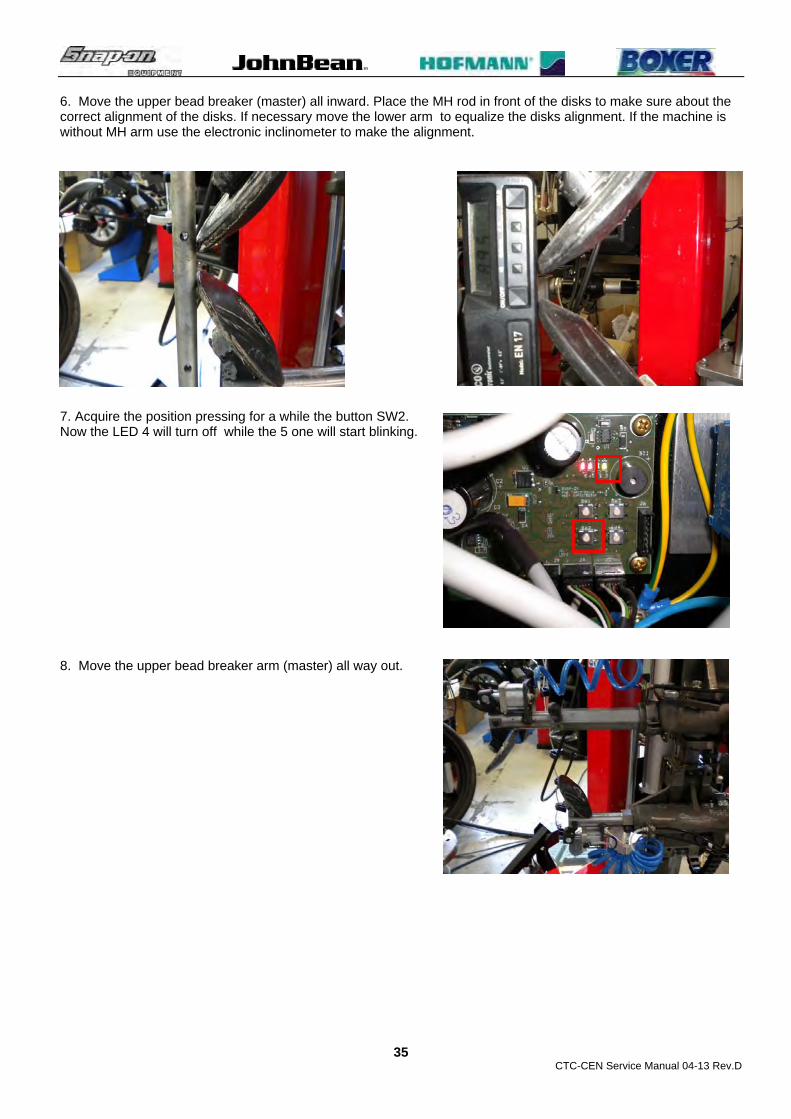
6. Move the upper bead breaker (master) all inward. Place the MH rod in front of the disks to make sure about the correct alignment of the disks. If necessary move the lower arm to equalize the disks alignment. If the machine is without MH arm use the electronic inclinometer to make the alignment.
7. Acquire the position pressing for a while the button SW2. Now the LED 4 will turn off while the 5 one will start blinking. 8. Move the upper bead breaker arm (master) all way out.

CTC-CEN Service Manual 04-13 Rev.D
36
9. Place the MH rod in contact with the upper bead breaker disk. 10. Press and hold the button SW3 to move the lower bead breaker arm outward and place the disk as closest to
the MH rod. Complete the alignment by moving manually the upper bead breaker arm.
If the machine is without MH arm use the electronic inclinometer to make the alignment.

CTC-CEN Service Manual 04-13 Rev.D
37
11. Acquire the position by pressing shortly the button SW2. Now the LEDs 4 and 5 will remain turned on to show that the acquiring of calibration points is done.
12 Press and hold SW2 to confirm and store the calibration. LEDs 4 and 5 will turn off and 2 further beeps will be
emitted to indicate the calibration is completed. Now the machine is ready to operate. 13 Turn off the machine. 14 Mount the cover to the electric box. 15 It is allowed to escape the calibration at any time by pressing the button SW4.

CTC-CEN Service Manual 04-13 Rev.D
38
CHAPTER 7 PNEUMATIC SECTION
7.1 PNEUMATIC FUNCTION
The pneumatic section is related to all those functions and devices controlled by air pressure. The working pressure required by machine to work properly must be from 8 to 12 bar and it is reported on the sticker label.
7.0.1 AIR PRESSURE CIRCUIT: The inlet air pressure is in the air filter - lubricator assy. This assembly is bolted to back of the bead breaker cabinet and it is equipped by a not adjustable air pressure regulator that reduces the over pressure to 10 Bar to avoid overstress to pneumatic components.
On the this tire changer all cylinders are supplied at the same pressure. In some cases there air flow reducers to reduce the speed of the device only.
7.0.2 FUNCTIONS DESCRIPTION: The description of the pneumatic functions can be grouped into 5 phases as following:
Air filter - lubricator assy. Inflation/bead seating function Tools cylinders function. Lift cylinder function. MH device function.
7.0.3 AIR FILTER LUBRICATOR ASSY The air pressure is controlled by the air pressure reducer and forwarded to water separator. Two output forward the dry air to the inflator valve and to the bead seating tank. One more outlet connect the water separator to the lubricator where an adjustable screw controls the oil drops to be added to the dry air to be supplied to all pneumatic cylinders.
7.0.4 INFLATION / BEAD BLASTER FUNCTION INFLATION: The dry air pressure reach the inflation spool valve. Pressing the valve pedal for half of its stroke,
1st stage, the dry air will go to the tire through to the air control valve that controls the tire inflating pressure during the inflating process. Releasing the pedal, the air contained in the tire will act the manometer showing the tire pressure. Pressing the air releasing button the tire pressure will be reduced.
BEAD BLASTER: The dry air pressure reach the air tank, equipped with a pressure relief valve set up at 12 bar. The bead blaster valve is basically a diaphragm valve and it is directly bolted to the tank. When inflator / blaster pedal is in rest position, air pressure is maintained equal on both sides of the diaphragm. Fully depressing the inflation pedal and the micro valve button simultaneously, air is allowed to exhaust through the controlled valve lowering the pressure inside of the diaphragm. Reduction of air pressure moves the diaphragm down allowing air from tank to flow to bead blaster jet.
7.0.5 DOUBLE ACTING CYLINDERS OPENING: The air flow arrives to the opened valve and reaches the side “A” of the cylinder.
Air contained in opposite side ”B” will escape through the coil valve. CLOSING:The air flow arrives to the opened valve and reaches the side “B” of the cylinder.
Air contained in opposite side ”A” will escape through the coil valve
7.0.6 SINGLE ACTING CYLINDERS
OPENING: The air flow arrives to the opened valve and reaches the side “A” of the cylinder. CLOSING: The air flow from the valve to side “A” is interrupted. Air contained in side ”A” will escape through the
valve due to external springs loading.
7.0.7 LIFT CYLINDER FUNCTION RAISING: The air flow is forced to the side “A” of the cylinder through the valve to raise the lift. Air contained in
side “B” will escape through the valves.
LOWERING: The air flow is forced to the side “B” of the cylinder 6.5 through the valve 6.2 to lower the lift.
7.0.8 MH DEVICE CYLINDER PRESSING: The air flow is forced to the side “A” of the cylinder 6.5 through the valve 6.2 to open the cylinder
and press the tire bead. Air contained in side “B” will escape through the valves.

CTC-CEN Service Manual 04-13 Rev.D
39
REALISING: The air flow is forced to the side “B” of the cylinder 6.5 through the valve 6.2 to close the cylinder and release the tire bead. Air contained in side “A” will escape through the valves.
7.2 AIR FILTER – LUBRICATOR ASSY # EAA0350G85A: CHECK AND REPLACEMENT : 30’ : Allen key 3mm, medium standard screwdriver. : Defective air filter lubricator assembly may cause the following malfunction: 1. Air leaking. 2. Oil leaking. 3. Incorrect air lubrication. 4. Slow pneumatic motion
TO CHECK THE AIR FILTER LUBRICATOR ASSY:
Air leaking and oil leaking can be solved only if they are caused by the glasses with the replacement of the glasses. In all other cases the replacement of the whole assembly is required.
TO REPLACE THE AIR FILTER LUBRICATOR ASSY: Disconnect the air pressure from the machine. Unplug the hoses. Loosen the bracket screws and remove the assy. Install the new air filter assy. Plug in the air hoses. Make the oil level. Connect the air pressure. Make the oil lubrication adjustment. Check if the machine works fine again.
TO REPLACE THE GLASSES: Disconnect the air pressure from the machine. Turn counter clockwise the glass to remove it from the assy. Take the new glass and tighten it. IMPORTANT!
BEFORE TIGHTENING THE LUBRICATOR GLASS, FILL IT WITH THE RECCOMENDED OIL ONLY AS REPORTED ON THE USER MANUAL AND ON TAG.
TO CHECK THE AIR LUBRICATION: Select the Service code C62 Ch2 to move the vertical lift alone. Move up and down the lift ‘til end of stoke and make sure, looking from the top transparent cap, that lubricator supplies one drop of oil every complete cycle of the lift.
TO ADJUST THE AIR LUBRICATION: Take a screwdriver and turn the regulator on top of the
transparent cap. Turning clockwise the oil drops will decrease. Turning counter clockwise the oil drops will increase.

CTC-CEN Service Manual 04-13 Rev.D
40
7.3 OPENING ARM CYLINDER # EAA0350G44A: CHECK AND REPLACEMENT
: 30’ : Allen key 6mm, 17 and 24mm end keys : Defective opening arm cylinder may cause the following malfunction: 1. External air leaking from the flange or from the piston rod 2. Air leaking from fittings. 3. The operating arm will not open or close and air leaking is reported from the valve TO CHECK THE EXTERNAL AIR LEAKING Position the cylinder where it leaks air. Check if the leaking is in between cylinder flange-cylinder liner or if it is coming from the piston rod. In case of need, place some soap with water on the interested part to better see where the leaking is coming
from.
TO CHECK THE FITTING AIR LEAKING Position the cylinder where it leaks air. Check if the leaking is in between the fitting and the cylinder flange. In case of need, place some soap with water on the interested part to better see where the leaking is coming
from.
TO CHECK THE CYLINDER WHEN OPERATING ARM WILL NOT OPEN OR CLOSE
Position the cylinder where it leaks air. Disconnect the air pipe where there is not any air pressure. If the air is getting out from the fitting, the swing cylinder is leaking air. If the air is getting out from the fitting, the control valve is leaking air.
TO REPLACE THE CYLINDER Unplug the machine from the air pressure. Disconnect the air pipes from the cylinder. Unlock the nut with 24mm end key and disconnect the cylinder
rod from the operating arm bushing.

CTC-CEN Service Manual 04-13 Rev.D
41
Remove the upper and lower securing screws and remove the cylinder.
Mount the new cylinder tightening the screws firmly. Mount the cylinder rod to the operating arm bushing: tighten the rod until it will touch the pin inside of the
bushing, then turn backward of 1 turn. Install the air pipes. Connect the air pressure and check if the machine works fine.
7.4 VALVE CONTROL OPENING ARM CYLINDER # EAA0356G96A:
CHECK AND REPLACEMENT
: 30’ : 4mm allen key,8 and 12mm end key, 10mm tube type key. : Defective valve may cause the following malfunction: 1. Air leaking from the valve. 2. The operating will not open or close and air leaking is reported from the valve TO CHECK THE VALVE: Remove the foot pedal assembly cover.
Check if there is any leaking in between valve rod and body. Position the cylinder where it leaks air. Disconnect the air pipe where there is not any air pressure. If the air is getting out from the fitting, the control valve is leaking
air.

CTC-CEN Service Manual 04-13 Rev.D
42
If there will not be any leaking from the fitting and pipe, but the air is getting out from the silencer of the other fitting, the valve has an internal leaking and must be replaced.
TO REPLACE THE VALVE: Disconnect the air pipes. Remove the four screws to have the get the valve dismounted.
Mount the new valve. Connect the air pipes. Plug the machine to the air pressure and to the power supply. Check if the machine works fine. Mount the foot pedal assembly cover.
7.5 VERTICAL LOCKING CYLINDER # EAA0344G32A: CHECK AND REPLACEMENT
: 1h : Allen key 4,5 and 6mm, 17mm end key, 13mm tube type key : Defective vertical locking cylinders may cause the following malfunction: 1. Air leaking from the cylinder. 2. The vertical rod does not remain blocked.. TO CHECK THE CYLINDER: Remove the cylinder cover. Press the yellow button of the valve to block the vertical rod of the operating arm. Check if the cylinder is leaking air in between cylinder liner and seal.

CTC-CEN Service Manual 04-13 Rev.D
43
TO REPLACE THE CYLINDER: Disconnect the air pressure and the power supply. Disconnect the air pipes from the cylinder.
Unlock the adjustment screw over the cylinder head and turn it
until it will out of the blocking plate range. Remove the washer from the cylinder.
Unlock and remove the two front adjustment screws and the two screws with springs.
Lift the blocking plate and extract the cylinder with robust screwdriver.
Install the new cylinder. Install the washer.
CTC-CEN Service Manual 04-13 Rev.D
44
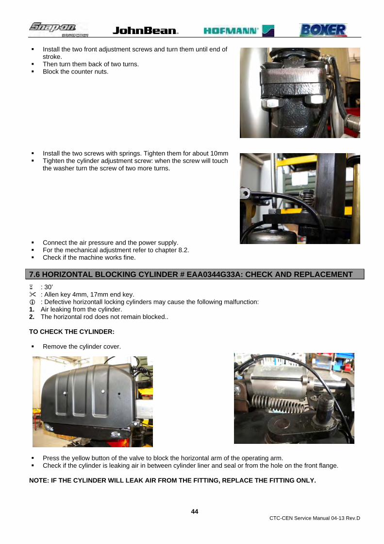
Install the two front adjustment screws and turn them until end of stroke.
Then turn them back of two turns. Block the counter nuts.
Install the two screws with springs. Tighten them for about 10mm Tighten the cylinder adjustment screw: when the screw will touch
the washer turn the screw of two more turns. Connect the air pressure and the power supply. For the mechanical adjustment refer to chapter 8.2. Check if the machine works fine.
7.6 HORIZONTAL BLOCKING CYLINDER # EAA0344G33A: CHECK AND REPLACEMENT
: 30’ : Allen key 4mm, 17mm end key. : Defective horizontall locking cylinders may cause the following malfunction: 1. Air leaking from the cylinder. 2. The horizontal rod does not remain blocked.. TO CHECK THE CYLINDER: Remove the cylinder cover.
Press the yellow button of the valve to block the horizontal arm of the operating arm. Check if the cylinder is leaking air in between cylinder liner and seal or from the hole on the front flange.
NOTE: IF THE CYLINDER WILL LEAK AIR FROM THE FITTING, REPLACE THE FITTING ONLY.
CTC-CEN Service Manual 04-13 Rev.D
45
TO REPLACE THE CYLINDER: Disconnect the air pressure and the power supply. Disconnect the air pipe from the cylinder. Remove the rear bolt and take out the cylinder. Mount the new cylinder.
NOTE: DO NOT OVERTIGHT THE BLOT. WHEN THE SCREW HEAD AND THE NUT WILL BE IN CONTACT WITH THE CYLINDER SUPPORT, STOP THE TIGHTENING.
Connect the air pipe from the cylinder. Connect the air pressure and the power supply. Check if the machine works fine. Install the cylinder cover.
7.7 VERTICAL ROD LIFT CYLINDER # EAA0363G79A: CHECK AND REPLACEMENT
: 30’ : 3 and 4mm allen keys, 10mm 30mm end key, rubber hammer. : Defective vertical rod cylinder may cause the following malfunction: 1. Air leaking from the cylinder. 2. The cylinder would not lift the vertical rod. TO CHECK THE CYLINDER: Pull the yellow button of the valve to allow the lifting the vertical rod. Check if the cylinder is leaking air.
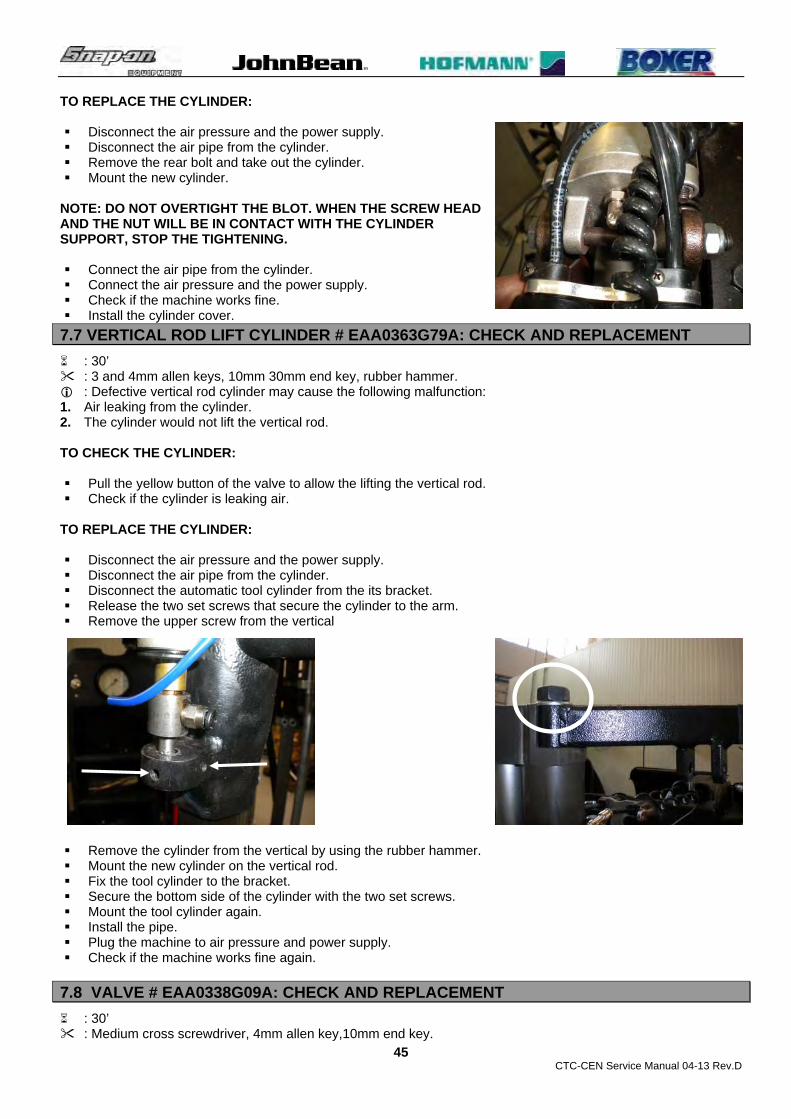
TO REPLACE THE CYLINDER: Disconnect the air pressure and the power supply. Disconnect the air pipe from the cylinder. Disconnect the automatic tool cylinder from the its bracket. Release the two set screws that secure the cylinder to the arm. Remove the upper screw from the vertical
Remove the cylinder from the vertical by using the rubber hammer. Mount the new cylinder on the vertical rod. Fix the tool cylinder to the bracket. Secure the bottom side of the cylinder with the two set screws. Mount the tool cylinder again. Install the pipe. Plug the machine to air pressure and power supply. Check if the machine works fine again.
7.8 VALVE # EAA0338G09A: CHECK AND REPLACEMENT
: 30’ : Medium cross screwdriver, 4mm allen key,10mm end key.

CTC-CEN Service Manual 04-13 Rev.D
46
: Defective valve may cause the following malfunction: 1. Air leaking from the valve rod or from the fittings. TO CHECK THE VALVE: Remove the cylinder cover.
Check if there is air leaking from the valve fittings or the valve rod.
TO REPLACE THE VALVE: Disconnect the air pressure and the power supply. Remove the handles
Disconnect the air pipes from the valve. Remove the two bolts to dismount the valve from the arm.

CTC-CEN Service Manual 04-13 Rev.D
47
Mount the new valve to the arm. Connect the air pipes to the valve. Mount the handles. Connect the air pressure and the power supply. Check the machine works fine. Mount the cylinder cover.
7.9 AUTOMATIC TOOL CYLINDER # EAA0363G81A: CHECK AND REPLACEMENT
: 30’ : 8 allen key, 19mm end key. : Defective automatic tool cylinder may cause the following malfunction: 1. Air leaking from the cylinder. 2. The cylinder would not lift the tire bead. TO CHECK THE EXTERNAL AIR LEAKING Position the cylinder where it leaks air. Check if the leaking is in between cylinder flange-cylinder liner or if it is coming from the piston rod. In case of need, place some soap with water on the interested part to better see where the leaking is coming
from.
TO CHECK THE FITTING AIR LEAKING Position the cylinder where it leaks air. Check if the leaking is in between the fitting and the cylinder flange. In case of need, place some soap with water on the interested part to better see where the leaking is coming
from.

CTC-CEN Service Manual 04-13 Rev.D
48
TO CHECK THE CYLINDER WHEN THE AUTOMATIC TOOL WILL NOT LIFT THE TIRE BEAD
Position the cylinder where it leaks air. Disconnect the air pipe where there is not any air pressure. If the air is getting out from the fitting, the tool cylinder is leaking air. If the air is getting out from the fitting, the control valve is leaking
air. TO REPLACE THE CYLINDER: Disconnect the air pressure and the power supply. Disconnect the air pipes from the cylinder. Disconnect the automatic tool cylinder from the its bracket and from the tool.
Mount the new cylinder to upper bracket. Connect the air pipes to the cylinder. Plug the machine to the air pressure and power supply. Connect the automatic tool cylinder to the tool. Perform the adjustment of the connection automatic tool – cylinder following par. 8.2. Check if the machine works fine.
7.10 AUTOMATIC TOOL CYLINDER VALVE # EAA0328G73A: CHECK AND REPLACEMENT
: 30’ : 3mm allen key,5,5 and 22mm end key. : Defective valve may cause the following malfunction: 1. Air leaking from the valve. 2. The cylinder would not lift the tire bead.
TO CHECK THE VALVE: Check the valve following Paragraph 7.8.
TO REPLACE THE VALVE: Disconnect the air pressure and the power supply.

CTC-CEN Service Manual 04-13 Rev.D
49
Disconnect the air pipe from the valve. Remove the round knob and the fixing nut.
Remove the 3 screws that secure the valve and the bracket together. Then disconnect the other 2 air pipes.
Mount the new valve. Connect the pipes. Secure the valve with the nut and mount its knob. Plug in the air pressure and power supply. Check if the machine works fine again.
7.11 BEAD BREAKER CYLINDERS # EAA0363G62A / EAA0351G77A:
CHECK AND REPLACEMENT
: 30’ each one : 24 and 13mm end key. : Defective bead breaker cylinder may cause the following malfunction: 1. Air leaking from the cylinder. 2. Air leaking from the control valve. 3. The bead breaker arm will not detach the tire bead. 4. The bead breaker arm goes down itself when machine remain not operated for some time. TO CHECK THE EXTERNAL AIR LEAKING Position the cylinder where it leaks air.

CTC-CEN Service Manual 04-13 Rev.D
50
Check if the leaking is in between cylinder flange-cylinder liner or if it is coming from the piston rod. In case of need, place some soap with water on the interested part to better see where the leaking is coming
from.
TO CHECK THE FITTING AIR LEAKING Position the cylinder where it leaks air. Check if the leaking is in between the fitting and the cylinder flange. In case of need, place some soap with water on the interested part to better see where the leaking is coming
from.
TO CHECK THE CYLINDER WHEN OPERATING ARM WILL NOT LIFT THE TIRE BEAD
Position the cylinder where it leaks air. Disconnect the air pipe where there is not any air pressure. If the air is getting out from the fitting, the swing cylinder is leaking air. If the air is getting out from the fitting, the control valve is leaking
air. TO REPLACE THE CYLINDER: Open completely the cylinder Secure the bead breaker carriage to the cabinet with a strong cord.

CTC-CEN Service Manual 04-13 Rev.D
51
Disconnect the cylinder from the carriage. Disconnect the air pressure and the power supply. Disconnect the air pipes from the cylinder.
Remove the bolt to disconnect the cylinder from the cabinet.
Secure the cylinder to the cabinet with the bolt. Connect the air pipes. Plug the machine to the air pressure and to power supply. Connect the cylinder to the bead breaker carriage. Remove the cord. Check if the machine works fine.
7.12 BEAD BREAKER CYLINDERS AND DISCS VALVES # EAA0350G58A / EAA0377G25A / EAA0350G57A: CHECK AND REPLACEMENT
: 30’ each one : 4mm allen key, 27mm end key, medium Philip screwdriver. : Defective valve may cause the following malfunction: 1. Air leaking from the control valve. 2. The bead breaker arm will not detach the tire bead. 3. The bead breaker arm goes down itself when machine remain not operated for some time.
TO CHECK THE VALVE: Remove the valves assembly cover. Check the valve following Paragraph 7.10. If there will not be any air leaking from air pipe and fitting, but
there is air leaking through trough one of the silencer, the valve must be replaced.

CTC-CEN Service Manual 04-13 Rev.D
52
TO REPLACE THE VALVE: Disconnect the air pressure and the power supply. Remove the knob and the nut. Remove the valve from the bracket.
Disconnect the pipes from the valve.
Mount the new joystick. Install the air pipes to the new valve. Snap in the new valve to the joystick. Plug the machine to the air pressure and power supply. Check if the machine works fine. Mount the valves assembly cover.
7.13 BEAD BREAKER ARMS BLOCKING CYLINDER # EAA0344G48A: CHECK AND REPLACEMENT
: 30’ : 4,5 and 6mm Allen key, 12 and 17mm end key, 13mm tube type key : Defective locking cylinders may cause the following malfunction: 1. Air leaking from the cylinder. 2. The bead breaker arm moves during the tire bead breaking. TO CHECK THE CYLINDER: Remove the cylinder cover.
CTC-CEN Service Manual 04-13 Rev.D
53
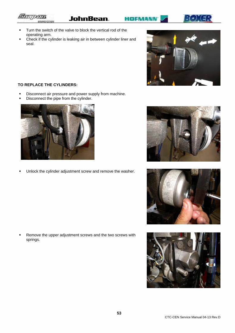
Turn the switch of the valve to block the vertical rod of the operating arm.
Check if the cylinder is leaking air in between cylinder liner and seal.
TO REPLACE THE CYLINDERS: Disconnect air pressure and power supply from machine. Disconnect the pipe from the cylinder.
Unlock the cylinder adjustment screw and remove the washer.
Remove the upper adjustment screws and the two screws with
springs.

CTC-CEN Service Manual 04-13 Rev.D
54
Move the blocking plate and push off the cylinder. Mount the new cylinder. Install the two front adjustment screws and turn them until end of stroke. Then turn them back of one turn. Block the counter nuts.
Install the two screws with springs. Tighten them for about 10mm.
Install the washer and tighten the cylinder adjustment screw: when
the screw will touch the washer turn the screw of two more turns. Connect the air pressure and the power supply. For the mechanical adjustment refer to par.8,7. Check if the machine works fine.

CTC-CEN Service Manual 04-13 Rev.D
55
7.14 BEAD BREAKER ARMS VALVE BLOCKING # EAA0377G26A: CHECK AND REPLACEMENT
: 30’ : 4mm allen key, 27mm end key, medium Philip screwdriver. : Defective valve may cause the following malfunction: 1. Air leaking from the control valve. 2. The bead breaker arm will not detach the tire bead. 3. The bead breaker arm goes down itself when machine remain not operated for some time.
TO CHECK THE VALVE: Remove the valves assembly cover. Check the valve following Paragraph 7.10. If there will not be any air leaking from air pipe and fitting, but there
is air leaking through one of the silencers, the valve must be replaced.
TO REPLACE THE VALVE: Disconnect the air pressure and the power supply. Lift with screwdriver the valve tang and pull the valve out. Remove the nut from the back to dismount the valve joystick.
Disconnect the pipes from the valve.
Mount the new joystick. Install the air pipes to the new valve. Snap in the new valve to the joystick.
CTC-CEN Service Manual 04-13 Rev.D
56
Plug the machine to the air pressure and power supply. Check if the machine works fine. Mount the valves assembly cover.
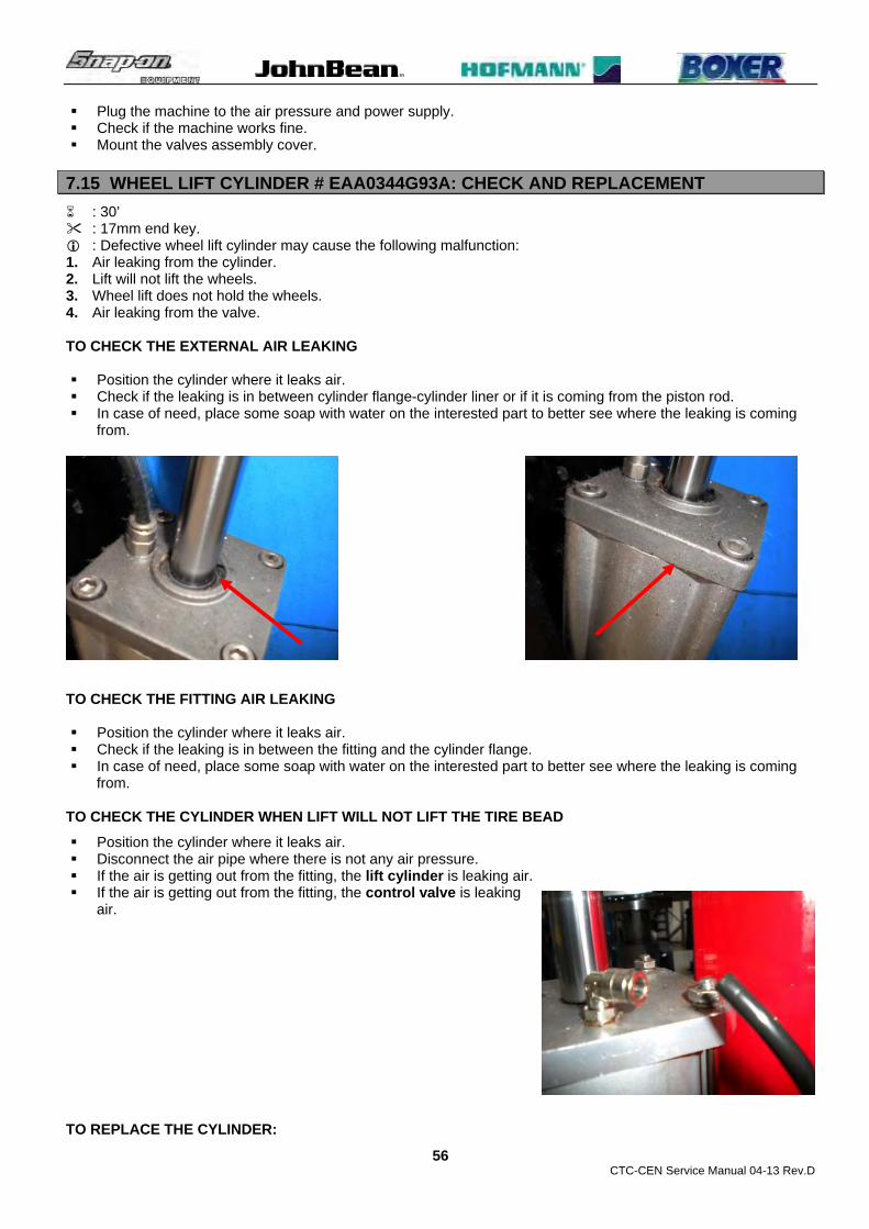
7.15 WHEEL LIFT CYLINDER # EAA0344G93A: CHECK AND REPLACEMENT
: 30’ : 17mm end key. : Defective wheel lift cylinder may cause the following malfunction: 1. Air leaking from the cylinder. 2. Lift will not lift the wheels. 3. Wheel lift does not hold the wheels. 4. Air leaking from the valve. TO CHECK THE EXTERNAL AIR LEAKING Position the cylinder where it leaks air. Check if the leaking is in between cylinder flange-cylinder liner or if it is coming from the piston rod. In case of need, place some soap with water on the interested part to better see where the leaking is coming
from.
TO CHECK THE FITTING AIR LEAKING Position the cylinder where it leaks air. Check if the leaking is in between the fitting and the cylinder flange. In case of need, place some soap with water on the interested part to better see where the leaking is coming
from.
TO CHECK THE CYLINDER WHEN LIFT WILL NOT LIFT THE TIRE BEAD
Position the cylinder where it leaks air. Disconnect the air pipe where there is not any air pressure. If the air is getting out from the fitting, the lift cylinder is leaking air. If the air is getting out from the fitting, the control valve is leaking
air. TO REPLACE THE CYLINDER:

CTC-CEN Service Manual 04-13 Rev.D
57
Open completely the cylinder Disconnect the air pressure and the power supply.
Remove the self locking nut of the stabilizer bar.
Remove the ring nut from the wheel holder. Remove the wheel holder.
Remove the screw from lift arm to disconnect the cylinder. Disconnect the air pipes from the cylinder. Remove the bolt from the to disconnect the cylinder from its
cabinet. Secure the cylinder to the cabinet with the bolt. Connect the air pipes. Fix the piston rod to the lift arm. Mount the wheel holder: the ring nut and the nut must be tightened until end of stroke and turned 1/8 of a turn
backward. Plug the machine to the air pressure and to power supply. Check if the machine works fine.

CTC-CEN Service Manual 04-13 Rev.D
58
7.16 WHEEL LIFT VALVE # EAA0349G00A: CHECK AND REPLACEMENT
: 30’ : 8 and 10mm end key, 3mm allen key, pliers. : Defective control valve may cause the following malfunction: 1. Air leaking from the valve. 2. Lift will not lift the wheels. 3. Wheel lift does not hold the wheels. 4. Wheel lift lower itself after releasing the pedal.
TO CHECK THE CONTROL VALVE:
Remove the valve cover. Check the valve according to paragraph 7.13. If there is not any air leaking from fitting and pipe but it is leaking from the air silencer, the valve must be
replaced.
TO REPLACE THE CONTROL VALVE:
Unplug the machine from air pressure and power supply. Remove the nut and the pin split.
Remove the connecting rod and the unscrew the bolts to release
the valve from the support. Unplug the air pipes from the valve.

CTC-CEN Service Manual 04-13 Rev.D
59
Plug the air pipes to the valve. Bolt the valve to the support. Mount the connecting rod and install the split pin and the self locking nut. Plug the machine to the air pressure and to power supply. Make sure that the rod adjustment is correct. If it not correct make the adjustment following the paragraph. Adjust the raising and lowering speed of the cylinder by adjusting
the two adjustable exhaust valve. Check if the machine works fine again. Mount the cover.
7.17 MH CYLINDER # EAA0345G61A: CHECK AND REPLACEMENT
: 30’ : End key 13mm. : Defective cylinder may cause the following malfunction: 1. Air leaking. 2. Low bead pushing pressure
TO CHECK THE MH CYLINDER:
Turn the machine on Lower the cylinder and check if it is leaking from the top flange. Raise the cylinder and check if it leaks air from the lower flange.
Lower the cylinder and remove the hose from the lower fitting. Keep pressing the control valve If the air comes out from the fitting the piston seal is defective. If the air comes out from the hose, the leaking is caused by the control valve. Make the same operation with the rear side.
TO REPLACE THE CYLINDER:
Disconnect ait pressure from the machine Unplug the air hoses from the cylinder. Remove the bead depressor. Loosen the four screws and remove the cylinder.

CTC-CEN Service Manual 04-13 Rev.D
60
Take the cylinder lock it to the MH arm. Plug the hoses Install the bead depressor. Connect the air pressure and check if it works fine again.
7.18 MH CYLINDER CONTROL VALVE #EAA0328G73A: CHECK AND REPLACEMENT
: 30’ : End key 5 and 22mm, Allen key 3mm. : Defective control valve may cause the following malfunction: 1. Air leaking 2. Low bead pushing pressure 3. Slow MH motion
TO CHECK THE MH CONTROL VALVE:
Follow paragraph 7.14
TO REPLACE THE MH CONTROL VALVE:
Disconnect the air pressure form the machine Remove the joystick knob and the nut Remove the control valve cover. Unscrew the screws that secure the valve to its cover.
Unplug the air hoses from the valve.

CTC-CEN Service Manual 04-13 Rev.D
61
Loosen the screws to take out the defective valve. Install the new valve and plug the air hoses. Connect the air pressure again. Adjust the lowering and raising cylinder speed by turning the two adjustable
exaust valve.
Mount the control valve cover. Check if the machine works fine again.
7.19 BEAD INFLATING VALVE # EAA0329G75A: CHECK AND REPLACEMENT
: 1h : Allen key 4 and 5mm, 8,10 and 13mm key. : Defective inflation spool valve may cause the following malfunction: 1. Air leaking. 2. No inflating action. 3. Air leaking from the blaster jet.
TO CHECK THE SPOOL VALVE:
Open the foot pedal assembly. Check if the mechanical components (springs, screws and linkage) are fine. Verify if the valve is leaking air from the rear springs when the pedal is in rest position. Verify if the valve is leaking air from front locking nuts when the pedal is in rest position.
TO REPLACE THE SPOOL VALVE:
Disconnect the air pressure from the machine. Turn the machine off. Unplug the hoses. Remove the collar. Loosen the three bracket screws.
Take the defective valve assy out and bolt the new one. Plug the hoses Press the pedal until it become hard to be pushed. Turn the nuts to set the clearance at about 4mm between the nut and the bracket.

CTC-CEN Service Manual 04-13 Rev.D
62
Lock the counter nut. Release the pedal. Now turn the linkage and the nut to set the clearance at about 8mm between the two nuts. Lock the nut to the linkage. Lock the valve to the pedal with the collar. Plug in the air pressure. Pressing half of spool valve pedal the air has to come out from the inflator only. Pressing the spool valve pedal all way down the air has to come out from the inflation hose and from the bead
seating jet at the same time. Install the foot pedal assembly cover.
7.20 BEAD BLASTER VALVE # 1-29581A AND AIR TANK : CHECK AND REPLACEMENT
: 1h : End key 12mm, big pliers. : Defective bead blaster valve may cause the following malfunction: 1. No air from air jet. 2. Air leaking from diaphragm.
TO CHECK THE BEAD BLASTER VALVE:
Verify if it is leaking air from the diaphragm. Verify it the bead seating jet is leaking air.
TO REPLACE THE BEAD BLASTER VALVE:
Disconnect the air pressure. Remove the hoses. Remove the valve from the tank niplex. Mount the new valve to the niplex. Install the hoses. Plug the air pressure and check if it works fine again.
7.21 AIR CONTROL # EAA0350G54A: CHECK AND REPLACEMENT
: 30’ : End key 8, 7 and 14mm, 4mm allen key. : Defective bead blaster valve may cause the following malfunction: 1. The valve does not stop the tire inflation. 2. The valve does not inflate the tire at all. 3. The valve leaks air.
TO CHECK THE VALVE:
Take a deflated wheel and inflate it. If the valve will show one of the above issue, it must be replaced.

CTC-CEN Service Manual 04-13 Rev.D
63
TO REPLACE THE VALVE: Disconnect the machine from the air pressure and power supply. Remove the foot pedal assembly protection. Disconnect the air pipes from the valve.
Loosen the screws that secure the foot pedal assembly to cabinet. Turn upside – down the foot pedal assembly and loosen the nuts that secure the valve to the pedal assembly. Mount the new valve. Secure the pedal assembly to the cabinet. Mount the air pipes. Connect the air pressure and the power supply. Check if the machine works fine. Mount the pedal assembly protection.
CTC-CEN Service Manual 04-13 Rev.D
64
CHAPTER 8 MECHANICAL SECTION
8.0 MECHANICAL SECTION
The mechanical section is connected to the centerpost, the tool and to the bead breakers adjustments. Usually this parts do not require the replacement and in any case their replacement is required after years of intensive working.
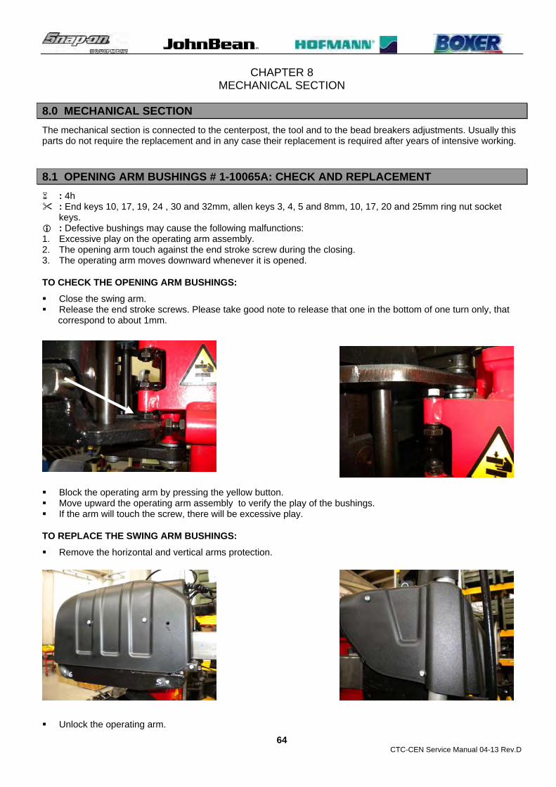
8.1 OPENING ARM BUSHINGS # 1-10065A: CHECK AND REPLACEMENT
: 4h : End keys 10, 17, 19, 24 , 30 and 32mm, allen keys 3, 4, 5 and 8mm, 10, 17, 20 and 25mm ring nut socket
keys. : Defective bushings may cause the following malfunctions: 1. Excessive play on the operating arm assembly. 2. The opening arm touch against the end stroke screw during the closing. 3. The operating arm moves downward whenever it is opened.
TO CHECK THE OPENING ARM BUSHINGS:
Close the swing arm. Release the end stroke screws. Please take good note to release that one in the bottom of one turn only, that
correspond to about 1mm.
Block the operating arm by pressing the yellow button. Move upward the operating arm assembly to verify the play of the bushings. If the arm will touch the screw, there will be excessive play.
TO REPLACE THE SWING ARM BUSHINGS:
Remove the horizontal and vertical arms protection. Unlock the operating arm.

CTC-CEN Service Manual 04-13 Rev.D
65
Disconnect the air pressure and the power supply. Disconnect the air pipes and the laser connector from the horizontal arm. Disconnect air pipes holder and the horizontal arm end stroke stopper. DANGER! THE HORIZONTAL ARM IS NOW FREE AND IT COULD GET OUT FROM ITS BASEMENT.
BE CAREFUL! VERY HEAVY AND UMBALNCED ASSEMBLY!TWO PEOPLE ARE REQUIRED FOR THE NEXT OPERATION DUE TO WEIGHT OF THE ASSEMBLY. IF TWO PEOPLE WILL NOT BE AVAILABLE IT IS MANDATORY TO DISMOUNT ALL COMPONENTS OF THE HORIZONTAL ARM TO MAKE IT LIGHTER. Slide out the horizontal arm carefully. Disconnect the opening cylinder following par.7.2.

CTC-CEN Service Manual 04-13 Rev.D
66
Remove the lower and the upper linkages. Remove the eccentric anti-rotational plate. Remove the ring nut and take out the screw and the eccentric.
BE CAREFUL! VERY HEAVY AND UMBALANCED ASSEMBLY!TWO PEOPLE ARE REQUIRED FOR THE NEXT OPERATION DUE TO WEIGHT OF THE ASSEMBLY. IF TWO PEOPLE WILL NOT BE AVAILABLE IT IS MANDATORY TO USE A LIFT Remove the operating arm basement . Replace the worn bushings. Mount the operating arm basement with the eccentric.

CTC-CEN Service Manual 04-13 Rev.D
67
BE CAREFUL! VERY HEAVY AND UMBALNCED ASSEMBLY!TWO PEOPLE ARE REQUIRED FOR THE NEXT OPERATION DUE TO WEIGHT OF THE ASSEMBLY. IF TWO PEOPLE WILL NOT BE AVAILABLE IT IS MANDATORY TO USE A LIFT Tighten the ring nut firmly until to lock the operating arm basement. Release the ring nut until the basement will start to swing by hand. Place the electronic inclinometer over the basement. Turn the eccentric until the inclinometer will show 0° in order to level the operating arm with the cabinet of the
machine. Install the anti-rotational plate. Make sure that the basement is still moving free. Mount the lower and the upper linkages. Tighten their ring nuts firmly and then turn back until the basement will
move freely again. Connect the opening cylinder following par.7.2. Mount the horizontal arm carefully. BE CAREFUL! VERY HEAVY AND UMBALNCED ASSEMBLY!TWO PEOPLE ARE REQUIRED FOR THE NEXT OPERATION DUE TO WEIGHT OF THE ASSEMBLY. IF TWO PEOPLE WILL NOT BE AVAILABLE IT IS MANDATORY TO MOUNT ALL COMPONENTS OF THE HORIZONTAL ARM ONE BY ONE DANGER! THE HORIZONTAL ARM IS NOT SECURED AND IT COULD GET OUT FROM ITS BASEMENT. Connect the horizontal arm end stroke stopper and the air pipes. Connect the air pipes and the laser connector to the horizontal arm. Connect the air pressure and the power supply. Check if the linkages are blocking properly following par.8.1.1. Move by hand the vertical screws adjustment until the hex heads will touch the basement. Then lock firmly the
nuts. Move by hand the sidewise adjustment screw until its head will touch the basement. Then lock firmly the nuts. Check if the machine works fine. Mount the protections.
CTC-CEN Service Manual 04-13 Rev.D
68
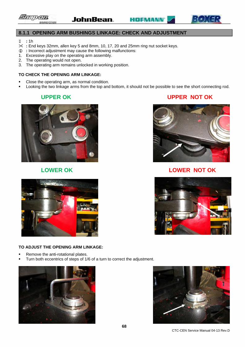
8.1.1 OPENING ARM BUSHINGS LINKAGE: CHECK AND ADJUSTMENT
: 1h : End keys 32mm, allen key 5 and 8mm, 10, 17, 20 and 25mm ring nut socket keys. : Incorrect adjustment may cause the following malfunctions: 1. Excessive play on the operating arm assembly. 2. The operating would not open. 3. The operating arm remains unlocked in working position.
TO CHECK THE OPENING ARM LINKAGE:
Close the operating arm, as normal condition. Looking the two linkage arms from the top and bottom, it should not be possible to see the short connecting rod.
UPPER OK UPPER NOT OK
LOWER OK LOWER NOT OK
TO ADJUST THE OPENING ARM LINKAGE:
Remove the anti-rotational plates. Turn both eccentrics of steps of 1/6 of a turn to correct the adjustment.

CTC-CEN Service Manual 04-13 Rev.D
69
Mount the anti-rotational plates. Check if the machine works fine.
8.2 AUTOMATIC TOOL # EAA0356G25A: CHECK – REPLACEMENT AND ADJUSTMENTS
: 1h : End key10,17 and 19mm, allen keys 3,5,6 and 8mm, rubber hammer, 13mm tube type key, rim of 17”. : Defective tool may cause the following malfunctions: 1. Tool is broken.
TO CHECK THE TOOL:
Check if the tool is broken or mechanically damaged.
TO REPLACE THE TOOL:
Disconnect the machine from air pressure and power supply Block the vertical rod with yellow button on the valve. Disconnect the tool from the cylinder. Loosen the screw underneath the tool and the two lateral set screws. Unlock the tool with the rubber hammer Remove completely the screws to complete the tool dismounting. Take the new tool and mount it to the vertical rod. Tighten all screws so that the tool is not rigidly locked in place but can turn through a small sector relative to the support hub.

CTC-CEN Service Manual 04-13 Rev.D
70
TO ADJUST THE TOOL ORIENTATION ON THE RIM:
Connect the machine to air pressure and power supply. Block a 17” rim diameter rim in good condition to the centerpost. Place the tool on the rim, as normal operation, and then lock it. Tighten one of the two adjuster screws until the tail of the tool is aligned to the rim edge. Tighten both screws, keeping the tool in this position. Move the tool away from the edge of the rim, then tighten the screw under the tool fully home.
TO ADJUST THE TOOL FINGER STROKE ON THE CONTROL CYLINDER:
Connect the ball joint to the cylinder rod. Move the control cylinder all way up.

CTC-CEN Service Manual 04-13 Rev.D
71
Connect the tool finger arm to the ball joint. If the holes are not matching, turn the ball joint until they will match.
Tighten the bolt firmly. Lower the finger completely: make sure that when the cylinder and tool finger will reach their end of stroke at
the same time. In case it need a fine adjustment turns the piston rod shaft only. Lock the upper ball joint nut. Check if the machine work fine.
TO ADJUST THE VERTICAL TOOL CLEARANCE:
Block a 17” rim diameter rim in good condition to the centre post. Unlock the front screws and tighten all way down and then turn
them backward of two turns each one. Lock the counter nuts. Place the tool on the rim, as normal operation, and then lock it. Make sure that the clearance between plastic protection and rim is
2mm. If the clearance is higher, release the arm, unlock the screws and
tighten them accordingly. Then lock the screws again. If the clearance is lower, release the arm, unlock the screws and
loosen them accordingly. Then lock the screws again. Check if the machine works fine

CTC-CEN Service Manual 04-13 Rev.D
72
TO ADJUST THE VERTICAL ROD BLOCKING PLATE:
Press the yellow button valve to lower completely the vertical tool rod. Tighten as much as possible the vertical blocking cylinder
adjustment screw in order to block the rod. Pull the yellow button valve all towards the operator in order to lift
the vertical tool rod. Turn counter clockwise the vertical blocking cylinder adjustment
screw until the vertical rod will move upward. Then perform some rod lowering and raising operations to make
sure that the rod is moving smoothly. Block the counter nut.
TO ADJUST THE VERTICAL ROD BLOCKING PLATE SPRINGS:
Block the vertical rod. Check if the spring are completely compressed.

CTC-CEN Service Manual 04-13 Rev.D
73
If they are completely compressed, turn the screws back until to see some light in between of the every wire of the spring.
Check if the machine works fine. Install the protection.
TO ADJUST THE HORIZONTAL TOOL CLEARANCE:
Block a 17” rim diameter rim in good condition to the centerpost. Unlock the horizontal arm. Unlock the rear screws and tighten them all way in. Then turn them
backward of two turns each one. Lock the counter nuts. Place the tool on the rim, as normal operation, and then lock it. Make sure that the clearance between plastic protection and rim is
2mm. If the clearance is higher, release the arm, unlock the screws and
tighten them accordingly. Then lock the screws again. If the clearance is lower, release the arm, unlock the screws and
loosen them accordingly. Then lock the screws again. Check if the machine works fine
TO ADJUST THE HORIZONTAL ARM BLOCKING PLATE:
Unlock the horizontal arm. Unlock the 6mm counter nuts Tighten as much as possible the horizontal blocking cylinder
adjustment set screws in order to block the arm. Turn counter clockwise both set screws at ½ turn every step until
the horizontal arm will move smoothly again. Block the counter nuts again. Mount the protection. Check if the machine works fine.

CTC-CEN Service Manual 04-13 Rev.D
74
8.3 HORIZONTAL ARM ROLLERS # EAA0347G76A: CHECK AND ADJUSTMENT
: 30’ : End keys 13mm, allen keys 4mm. : Incorrect rollers adjustment may cause the following malfunctions: 1. Excessive play on the horizontal arm. 2. Horizontal arm does not move smoothly. TO CHECK THE ROLLERS: Remove the horizontal arm protection. Unlock the horizontal arm cylinder. Unlock the counter nuts and then loosen the set screws to release the rollers. Unlock completely the front and the rear rollers Rotate the rollers and check if they are worn out or damaged TO ADJUST THE ROLLERS: Tighten all 4 setscrews until to block the horizontal arm. Then turn back every one of ½ of a turn to get the
horizontal arm free again. Now make a fine adjustment tightening or loosening of 1/8 of a turn every setscrew. When the arm will move smoothly again and there will not be excessive play on the arm, lock the counter nuts. Mount the cover again.
8.4 GEAR BOX: CHECK AND REPLACEMENT
: 2h : End keys 17mm, allen keys 4mm, Seeger pliers. : Incorrect gearbox may cause the following malfunctions: 1. Noisy rotation. 2. Low rotation torque. 3. Oil leaking.
TO CHECK GEARBOX:
Turn the machine off. Remove the belt from the motor following par.5.4 Turn the machine on. Run the motor: if it is run normally it means that the gearbox is noisy and must be replaced.
TO REPLACE THE GEARBOX:
Turn the machine off. Loosen the 2 nuts and the screws of the center-post to release it. Remove the turntable center-post assembly.
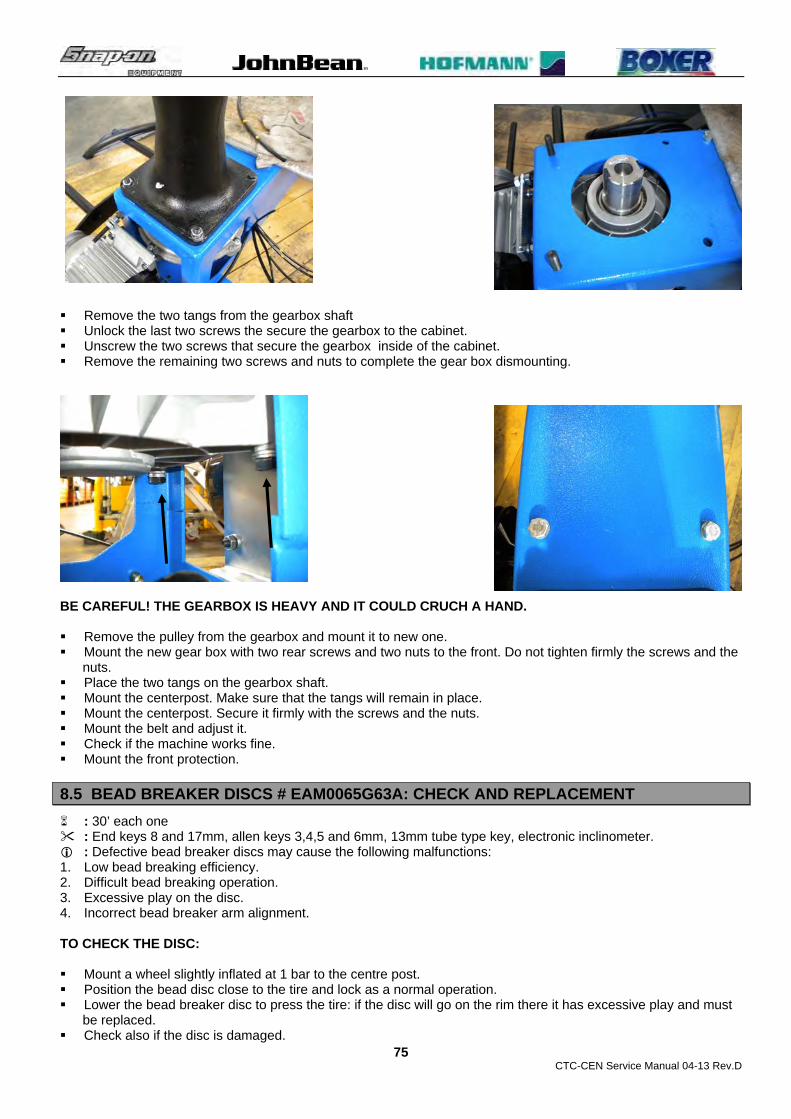
CTC-CEN Service Manual 04-13 Rev.D
75
Remove the two tangs from the gearbox shaft Unlock the last two screws the secure the gearbox to the cabinet. Unscrew the two screws that secure the gearbox inside of the cabinet. Remove the remaining two screws and nuts to complete the gear box dismounting.
BE CAREFUL! THE GEARBOX IS HEAVY AND IT COULD CRUCH A HAND. Remove the pulley from the gearbox and mount it to new one. Mount the new gear box with two rear screws and two nuts to the front. Do not tighten firmly the screws and the
nuts. Place the two tangs on the gearbox shaft. Mount the centerpost. Make sure that the tangs will remain in place. Mount the centerpost. Secure it firmly with the screws and the nuts. Mount the belt and adjust it. Check if the machine works fine. Mount the front protection.
8.5 BEAD BREAKER DISCS # EAM0065G63A: CHECK AND REPLACEMENT
: 30’ each one : End keys 8 and 17mm, allen keys 3,4,5 and 6mm, 13mm tube type key, electronic inclinometer. : Defective bead breaker discs may cause the following malfunctions: 1. Low bead breaking efficiency. 2. Difficult bead breaking operation. 3. Excessive play on the disc. 4. Incorrect bead breaker arm alignment. TO CHECK THE DISC: Mount a wheel slightly inflated at 1 bar to the centre post. Position the bead disc close to the tire and lock as a normal operation. Lower the bead breaker disc to press the tire: if the disc will go on the rim there it has excessive play and must
be replaced. Check also if the disc is damaged.

CTC-CEN Service Manual 04-13 Rev.D
76
TO REPLACE THE DISC: Remove the plastic protection. Remove the rollpin. Then remove the bushing. Remove the washers and then loosen the four screws to complete the dismounting of the disc. Mount the pin to the disc and secure the screws with Loctite. Then replace the old washers with the new ones. Mount the disc assembly to the bead breaker arm holder. Install the roll pin again. Install the protection. Check if the machine works fine again.
8.6 BEAD BREAKER DISCS # EAM0065G63A: CHECK AND REPLACEMENT
: 30’ Each one : Allen key 4mm. : Bad bead breaker disc may cause the following malfunction: 1. Disc touches the rim during bead breaking operation. 2. The disc is broken
TO CHECK THE DISC:
Turn the machine off. Check if the bead breaker discs are damaged or worn out.
TO REPLACE THE BEAD BREAKER DISC

CTC-CEN Service Manual 04-13 Rev.D
77
Loose the four screws that secure the disc to its support. Remove the defective disc. Install the new disc and secure it with the screws and Loctite. Perform the bead breaker discs alignment calibration (6.5).
8.7 BEAD BREAKER DISC BEARING# 1-06963A: CHECK AND REPLACEMENT : 30’ Each one : Allen key 2,5, 3 and 4. Key of 19mm : Defective bad bead breaker disc bearing may cause the
following malfunctions: 1. Disc touches the rim during bead breaking operation. 2. The bead breaker disc goes on the tire sidewall during bead
breaking. 3. The disc is broken.
TO CHECK THE BEAD BREAKER DISC BEARING:
Turn the machine off. Check if the bead breaker disc show a lot of play.
TO REPLACE THE BEAD BREAKER DISC BEARING
Remove the red plastic cover. Remove the bead breaker disc (8.6). Loose the lateral set screw with the 3mm allen key. Loose the 12mm screw with the 19mm end key and remove the
defective bearing from the arm. Remove the defective bearing from the spacer. Take the new bearing and install it on the spacer.
Install the new bearing with loctite to the support. Tighten the 12mm screw firmly. Tighten again the lateral set screw. Mount again the bead breaker disc. Turn the machine and perform the bead breaker discs alignment
calibration (6.5). Turn the machine on and check if it works fine

CTC-CEN Service Manual 04-13 Rev.D
78
8.8 BEAD BREAKER DISCS INCLINATION ADJUSTMENT
: 30’ each one : Allen keys 4 and 5, electronic inclinometer. : Incorrect bead breaker discs inclination may cause the following malfunctions: 1. Low bead breaking efficiency. TO CHECK THE DISC INCLINATION: Remove the protection. Leave the bead breaker disc in rest position. Position the electronic inclinometer on the disc. Make sure that the inclination from 50° to 51°.
Then press the joystick to change the disc inclination: it must be from 35 to 36°. TO ADJUST THE DISC INCLINATION: Remove the counter setscrews from the bead breaker holder. To adjust the inclination of the disc in rest position, turn the upper
set screw. To adjust the inclination of the disc in second stage turn the lower
setscrew. Secure the setscrews with the counter setscrews and Loctite. Mount the protection. Check if the machine works fine.
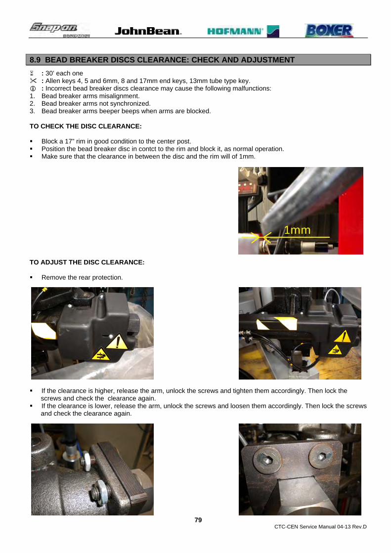
CTC-CEN Service Manual 04-13 Rev.D
79
8.9 BEAD BREAKER DISCS CLEARANCE: CHECK AND ADJUSTMENT
: 30’ each one : Allen keys 4, 5 and 6mm, 8 and 17mm end keys, 13mm tube type key. : Incorrect bead breaker discs clearance may cause the following malfunctions: 1. Bead breaker arms misalignment. 2. Bead breaker arms not synchronized. 3. Bead breaker arms beeper beeps when arms are blocked. TO CHECK THE DISC CLEARANCE: Block a 17” rim in good condition to the center post. Position the bead breaker disc in contct to the rim and block it, as normal operation. Make sure that the clearance in between the disc and the rim will of 1mm. TO ADJUST THE DISC CLEARANCE: Remove the rear protection. If the clearance is higher, release the arm, unlock the screws and tighten them accordingly. Then lock the
screws and check the clearance again. If the clearance is lower, release the arm, unlock the screws and loosen them accordingly. Then lock the screws
and check the clearance again.

CTC-CEN Service Manual 04-13 Rev.D
80
Perform the bead breaker arm calibration. Check if the machine works fine. Mount the protection again. TO CHECK AND ADJUST THE UPPER BEAD BREAKER AMR BLOCKING CYLINDER: Please refer to par.8.2 for the adjustment. Check if the arm moves smoothly pushing and pulling it by hand. Perform the bead breaker arm calibration. Check if the machine works fine Mount the protection. TO CHECK AND ADJUST THE LOWER BEAD BREAKER AMR BLOCKING CYLINDER: Please refer to par.5.5 to disconnect and connect the actuator. Please refer to par.8.2 for the adjustment. Check if the arm moves smoothly pushing and pulling it by hand. Perform the bead breaker arm calibration. Check if the machine works fine Mount the protection. TO CHECK AND ADJUST BEAD BREAKER AMR BLOCKING PLATE SPRINGS: Please refer to par.8.2. Check if the machine works fine Mount the protection.
8.10 BEAD BREAKER CARRIAGE: CHECK AND ADJUSTMENT
: 30’ each one : Allen keys 4, 5 and 6mm, 8 and 17mm end keys, 13mm tube type key. : Incorrect bead breaker carriage adjustment may cause the
following malfunctions: 1. Excessive play. 2. Bead breaker arms not synchronized. 3. Difficult Bead breaking operation. TO CHECK THE BEAD BREAKER CARRIAGE: Check if the rollers and the bronze pads are damaged or worn
out. If necessary loosen the setscrews and replace the damaged units.

CTC-CEN Service Manual 04-13 Rev.D
81
TO ADJUST THE BEAD BREAKER CARRIAGE: Tighten all setscrews unless lock rigidly the carriage on the
squared bar. Move the carriage up and down and make sure that will move unless jerking.
In case the carriage will jerk, stop the movement and adjust the screws. Then continue the control.
When the carriage will move smoothly without any significant play, block all counter nuts.
Perform the bead breaker arm calibration. Check if the machine works fine.
8.11 LEAD SCREW NUT # EAM0076G10A : CHECK AND REPLACEMENT
: 1h : Allen keys 4, and 5, 8 and 13mm end keys, Loctite. : Worn lead nut screw may cause the following malfunctions: 1. Bead breaker arms not synchronized. 2. Bead breaker arms beeper beeps when arms are locked. 3. Lower Bead breaker arm moves forward and backward unless find the correct position. TO CHECK THE LEAD NUT: Disconnect the air pressure and power supply. Disconnect the actuator following the par.5.5 Move forward and backward by hand the actuator worm screw to check if there is play. If yes the
nut is worn out and must be replaced. TO REPLACE THE LEAD NUT: Remove the actuator worm screw from the lead nut following the par.5.5. Unscrew the lead nut from the holder. Mount the new nut and secure it with Loctite. Mount the actuator following par.5.5. Perform the bead breaker arms calibration.

CTC-CEN Service Manual 04-13 Rev.D
82
CHAPTER 9
TROUBLE SHOOTING SECTION COMPLAINT 1: Turning the machine on the centerpost does not turn, the lower bead breaker arm does not move at all and the laser pointer does not turn on. 1. Check the power supply at the wall. 2. Check the power supply plug and fuses on the wall: 5.1 3. Check the power supply cable: 5.1 4. Check the transformer fuses:5.6 5. Check the CPU board fuses:6.2 6. Check the rotary switch: 5.2 7. Call Snap On Hot Line Center COMPLAINT 2: Turning the machine on the centerpost does not turn. The lower bead breaker arm and the laser pointer are working fine. 1. Check the centerpost switc: 5.7 2. Check the Inverter: 6.1 3. Check the inverter wiring: 6.1 4. Check the centerpost motor cable: 5.3 5. Check the centerpost motor: 5.4 6. Call Snap On Hot Line Center COMPLAINT 3: Turning the machine on the lower bead breaker arm does not move. Centerpost rotation and the laser pointer are working fine. 1. Check the transformer fuse:5.6 2. Check the CPU board fuses:6.2 3. Check the transformer: 5.6 4. Check the bead breaker potentiometers:6.3 5. Check the lower bead breaker arm actuator:5.5 6. Check the CPU board: 5.5 7. Call Snap On Hot Line Center COMPLAINT 4: Turning the machine on the centerpost turns 1st speed clockwise only, or in 2nd speed only, or counter clockwise only. 1. Check the centerpost switch: 5.7 2. Check the centerpost switch mechanical adjustment: 5.7 3. Check the inverter wiring: 6.1 4. Check the Inverter: 6.1 5. Check the centerpost motor: 5.4 6. Call Snap On Hot Line Center COMPLAINT 5: The centerpost shows low rotational torque during mounting/dismounting operations. 1. Check the power supply at the wall. 2. Check the power supply plug : 5.1 3. Check the power supply cable: 5.1 4. Check the rotary switch: 5.2 7. Check the Inverter: 6.1 8. Check the inverter wiring: 6.1 9. Check the centerpost motor cable: 5.3 10. Check the centerpost motor: 5.4 11. Check the gearbox: 8.4 12. Call Snap On Hot Line Center. COMPLAINT 6: The wheel lift does not lift the wheels. 1. Check the air pressure inlet:7.2 2. Check the air filter: 7.1 3. Check the wheel lift cylinder: 7.15 4. Check the wheel lift valve: 7.16 5. Call Snap On Hot Line Center.

CTC-CEN Service Manual 04-13 Rev.D
83
COMPLAINT 7: Pressing the pedal the operating arm does not close or open. 1. Check the air pressure inlet: 7.2 2. Check the opening arm cylinder: 7.3 3. Check the opening arm cylinder valve: 7.4 4. Check the opening arm end stroke screws: 8.1 5. Check the opening arm bushing linkage: 8.1.1 6. Call Snap On Hot line Center. COMPLAINT 8: When the operating arm opens it moves downward and when it closes it catches against the end stroke screws.. 1. Check the opening arm end stroke screws: 8.1 2. Check the play of the arm: 8.1 3. Check the opening arm bushings: 8.1 4. Call snap On Hot Line Center COMPLAINT 9: The tool damages the rims. 1. Check if the wheel is firmly blocked to the centerpost. 2. Check the plastic protection. 3. Check if the vertical clearance is correct:8.2 4. Check the horizontal clearance: 8.2 5. Check the tool adjustment: 8.2 6. Call Snap On Hot Line Center COMPLAINT 10: The bead breakers do not detach the tire bead. 1. Check the air pressure inlet: 7.1 2. Check the bead breaker cylinder: 7.11 3. Check the bead breaker cylinder and discs valves:7.12 4. Check the bead breaker discs clearance:8.7 5. Check the bead breaker disc inclination 8.6 6. Check the bead breaker carriage:8.8 7. Call Snap On Hot Line Center. COMPLAINT 11: The air control does not inflate the tire. 1. Check the air control: 7.21 COMPLAINT 12: All pneumatic cylinders are too slow. 1. Check airline pressure inlet: 7.2 2. Check the air pressure outlet: 7.2 3. Check the air filter –lubricator assembly:7.2 4. Call Snap On Hot Line Center COMPLAINT 13: The MH arm does not have force. 1. Check airline pressure inlet: 7.2 2. Check the air pressure outlet: 7.2 3. Check the air filter –lubricator assembly:7.2 4. Check the MH cylinder: 7.17 5. Check the MH valve: 7.18 6. Call Snap On Hot Line Center COMPLAINT 14: The automatic tool does not lift the tire bead. 1. Check airline pressure inlet: 7.2 2. Check the air pressure outlet: 7.2 3. Check the air filter –lubricator assembly:7.2 4. Check the automatic tool cylinder:7.9 5. Check the automatic tool cylinder valve: 7.10 6. Call Snap On Hot Line Center COMPLAINTS 15: The bead breaker arms are locked but the beeper beeps. 1. Check the bead breaker potentiometers:6.3 2. Check the lower bead breaker arm actuator:5.5 3. Check the CPU board: 5.5 4. Check the bead breaker discs clearance:8.7

CTC-CEN Service Manual 04-13 Rev.D
84
5. Call Snap On Hot Line Center COMPLAINT 16: The bead breaker discs are not aligned 1. Check the bead breaker potentiometers:6.3 2. Check the lower bead breaker arm actuator:5.5 3. Check the CPU board: 5.5 4. Check the bead breaker discs clearance:8.7 5. Call Snap On Hot Line Center

CTC-CEN Service Manual 04-13 Rev.D
85
CHAPTER 10
SERVICE BULLETINS
Service-Bulletin No. SB 852 TC 10-May-12
Models affected: All passenger tire changer with tire inflator Alle Pkw-Reifenmontiermaschinen mit Füllvorrichtung
Starting from s/n:
Subject: Homologated Wika manometer 0023484 accuracy Genauigkeit des geprüften Wika-Manometers 0023484
ENGLISH Following up some cases of Wika manometer # 0023484 replaced under warranty due to inaccurate tire pressure reading, we would like to inform you that that the homologated accuracy of the manometer is the following:
UP TO 4 BAR: ± 0.08 bar
FROM 4 TO 10 BAR: ± 0.16 bar
OVER 10 BAR: ± 0.25 bar
Please take good note that if the manometer shows the tire pressure within these tolerances and if its arrow returns to zero after disconnecting the inflating hose from the wheel, it does not have to be replaced.
In case the manometer will not return to zero, before replacing it we recommend to remove the rear sintered air filter absorber # 0019181, shown in the picture, and make sure that the manometer will return to zero. If the manometer will return to zero replace the sintered air filter absorber # 0019181.
The replaced manometers under warranty due to low accuracy will be inspected and if they will show pressure within the homologated tolerances, we will be forced to invoice them.
DEUTSCH Nachdem einige Wika-Manometer # 0023484 aufgrund ungenauer Reifendruckanzeige unter Gewährleistung ausgetauscht wurden, möchten wir hier nochmals auf die geprüfte Genauigkeit des Manometers aufmerksam machen:
bis 4 bar: ± 0.08 bar
von 4 bis 10 bar: ± 0.16 bar
über 10 bar: ± 0.25 bar
Bitte beachten, wenn die Druckanzeige des Manometers innerhalb dieser Toleranzen liegt und der Zeiger nach dem Abnehmen des Füllschlauches vom Rad wieder in Nulllage zurückkehrt, muss das Manometer nicht ausgetauscht werden.
Falls der Zeiger nicht in Nulllage zurückkehrt, empfehlen wir – wie im Bild gezeigt – vor Austausch des Manometers noch den hinteren Luftfilter # 0019181 abzunehmen und zu prüfen, ob der Zeiger dann in Nulllage zurückkehrt. Falls dies geschieht, den Luftfilter # 0019181 auswechseln.
Manometer, die aufgrund ungenügender Genauigkeit unter Gewährleistung ausgetauscht werden, werden im Werk überprüft. Falls es sich zeigt, dass die Druckanzeige innerhalb der geprüften Toleranzen liegt, müssen wir das Teil leider in Rechnung stellen.
ITALIANO A seguito di alcuni casi di manometri Wika # 0023484 sostituiti in garanzia a seguito della lettura imprecisa della pressione degli pneumatici, gradiamo informarvi che la precisione omologata del manometro è la seguente:

CTC-CEN Service Manual 04-13 Rev.D
86
FINO A 4 BAR: ± 0.08 bar
DA 4 A 10 BAR: ± 0.16 bar
OLTRE 10 BAR: ± 0.25 bar
Prego prendere ben nota che se il manometro mostra la pressione degli pneumatici entro queste tolleranze e se la sua lancetta ritorna a zero dopo aver staccato il tubo di gonfiaggio dalla ruota, non deve essere sostituito.
Nel caso in cui il manometro non ritorni a zero, prima di sostituirlo raccomandiamo di scollegare il filtro sinterizzato smorzatore posteriore # 0019181, mostrato in figura, e assicuratevi che il manometro ritorni a zero. Se il manometro non ritorna a zero sostituite il filtro sinterizzato smorzatore # 0019181.
I manometri sostituiti in garanzia per mancata accuratezza verranno controllati al rientro e, se trovati nelle tolleranze omologate, saremo costretti a fatturarli.
ESPAÑOL Después de algunos casos de manómetros Wika # 0023484 sustituidos en garantía por causa de una lectura imprecisa de la presión del neumático, nos complace informarles que la precisión homologada del manómetro es la siguiente:
HASTA 4 BAR: ± 0.08 bar
DE 4 A 10 BAR: ± 0.16 bar
MÁS DE 10 BAR: ± 0.25 bar
Pido tomar buena nota de que si el manómetro muestra la presión del neumático entre estas tolerancias y la aguja retorna a cero después de quitar el tubo de inflado de la rueda, no debe ser sustituido.
En el caso en que el manómetro no vuelve a cero, antes de sustituirlo recomendamos desconectar el filtro absorvente posterior # 0019181, mostrado en la figura, y asegurarse que el manómetro vuelve a cero. Si el manómetro vuelve a cero sustituir el filtro absorvente posterior # 0019181.
El manómetro sustituido en garantía por falta de precisión se comprobarán al retorno, y si se comprueba la tolerancia homologada, nos veremos obligados a cobrarlo.
FRANÇAIS Après avoir dû remplacé des manomètres Wika # 0023484 sous garantie qui avaient comme défaut une mesure imprécise de la pression des pneus, nous souhaitons vous informer que la précision homologuée du manomètre est la suivante :
JUSQU’A 4 BARS : ± 0.08 bar
DE 4 A 10 BARS : ± 0.16 bar
PLUS DE 10 BARS : ± 0.25 bar
Prière de prendre bien note que si le manomètre indique une pression des pneus dans les limites de ces tolérances et si l’aiguille retourne à zéro après avoir débranché le tube de gonflage de la roue, il ne doit pas être remplacé.
Dans le cas où le manomètre ne retournerait pas à zéro, avant de le remplacer, nous recommandons de débrancher le filtre synthérisé arrière # 0019181, illustré dans la figure, et s’assurer que le manomètre retourne à zéro. Si le manomètre ne retourne pas à zéro, remplacez le filtre synthérisé # 0019181.
Les manomètres remplacés sous garantie parce qu’ils ont un défaut de précision seront contrôlés à leur retour en usine et s’ils rentrent dans les tolérances homologuées, nous serons dans l’obligation de les facturer.

CTC-CEN Service Manual 04-13 Rev.D
87
Service-Bulletin No. SB 867 TC 13-Jul-12
Models affected: Mounting Help arms
Starting from s/n:
Subject: Control of the MH arm control valve
ENGLISH
Feedback from the field reported cases of air leaking from the aluminum made control valve or slow self - lowering of the Mounting Hel arm due to the loosened end cap screws.
The issue was solved by tighten firmly the end cap screws with Loctite.
In case you will receive same complaints from the field, it is recommended to tighten the end cap screws with Loctite before replacing the control valve.
In case of valve replacement we kindly ask to take good note to do order the kit control valve # EAA0377G99A instead of the valve # EAA0328G73A.
The kit contains the necessary screws and nuts to allow the installation of the present Stampotecnica’s control valve on the Mounting Help arm.
ITALIANO Riscontri dal campo riportano casi di perdita di aria dalla valvola di comando prodotta in alluminio o lento auto - abbassamento del braccio premitallone MH dovute allo svitamento delle viti del coperchio della valvola.
La lamentela è stata risolta avvitando le viti coperchio valvola con Loctite.
In caso riceviate lamentele identiche dal campo, è raccomandato di controllare il serraggio delle viti del coperchio valvola con Loctite prima di sostituire la valvola.
In caso di sostituzione valvola, vi preghiamo di prendere ben nota di ordinare il Kit valvola di comando MH # EAA0377G99A anziché solo la valvola # EAA0328G73A.
Il kit contiene le viti ed i dadi necessari all’installazione dell’attuale valvola della Stampotecnica sul braccio premitallone.
DEUTSCH Aus der Praxis erreichen uns Berichte über Luftverluste aus dem Steuerventil aus Aluminium oder über langsames, selbstständiges Sinken des MH-Montagearms durch Lockerung der Schrauben am Ventildeckel.
Die Probleme wurden gelöst, indem die Schrauben am Ventildeckel mit Loctite festgeschraubt wurden.
Falls Sie ähnliche Beschwerden aus der Praxis hören, lassen Sie bitte die Schrauben des Ventildeckels mit Loctite festziehen, bevor Sie das Ventil auswechseln.
Falls das Ventil doch ausgewechselt wird, bitten wir Sie, darauf zu achten, das Set für das Steuerventil (# EAA0377G99A) anstatt nur das Ventil alleine (# EAA0328G73A) zu bestellen.
Das Set enthält die nötigen Schrauben und Muttern, um das jetzige Ventil von Stampotecnica am Montagearm zu installieren
FRANÇAIS Il a été observé sur site des cas de fuites d’air de la soupape de commande fabriquée en aluminium ou encore un lent abaissement du bras presse-talon MH, dus au fait que les vis du couvercle de la soupape étaient desserrées. Le problème a été résolu en resserrant les vis du couvercle de la soupape avec du Loctite.

CTC-CEN Service Manual 04-13 Rev.D
88
Dans le cas où vous recevriez une réclamation identique d’un client, il est recommandé de contrôler d’abord le serrage des vis du couvercle soupape avec du Loctite avant de remplacer la soupape.
Dans le cas d’un remplacement de la soupape, nous vous prions de mentionner dans l’ordre de commande le Kit soupape de commande MH # EAA0377G99A et non pas la soupape # EAA0328G73A.
Le Kit contient les vis et les écrous nécessaires à l’installation de la soupape courante Stampotecnica sur le bras presse-talon.
ESPAÑOL Se han recibido desde la calle casos de perdida de aire de la válvula de mando producida en aluminio o una auto bajada lenta del brazo presiona talones MH, debido a que los tornillos de la tapa de la vávula se aflojan.
La queja se ha resuelto fijando los tornillo de la tapa de la válvula con Loctite.
En el caso de recivir identica queja de la calle, se recomienda fijar los tornillos de la tapa de la válvula con Loctite antes de sustituirla.
En caso de sustituir la válvula, pedimos de tomar buena nota de pedir el kit válvula de mando MH # EAA0377G99A en lugar de la válvula sola # EAA0328G73A.
El Kit contiene los tornillos y las tuercas necesarias para la instalación de la válvula actual Stampotecnica en el brazo presiona talón.

CTC-CEN Service Manual 04-13 Rev.D
89
Service-Bulletin No. SB 879 TC 23-Jul-12
Models affected: ATC 900, Monty 8600, Centaur, Vulcan Pro
Starting from s/n: 0612.EEWH42AE1.8
Subject: Wired multiturn potentiometer
ENGLISH
We would like to inform you that starting from the above serial number all the reported machine models are equipped by the bead breaker potentiometers with a unique cable to be directly connected to the CPU board.
Previously, the potentiometers were equipped with short cables and connected to the CPU board through an extension wires.
In case of need please order the following parts:
1 x # EAA0377G07A POTENTIOMETER WITH CABLE MASTER
1 x # EAA0377G08A POTENTIOMETER WITH CABLE SLAVE
ITALIANO Gradiamo informarvi che a partire dal numero di matricola sopra riportato, tutti i modelli di macchine sopra indicati sono equipaggiati con i potenziometri dei bracci stallonatori con un cavo unico che si collega direttamente alla scheda CPU.
In precedenza i potenziometeri erano dotati di cavi corti collegati alla scheda CPU attraverso delle prolunghe.
In caso di necessità ordinate gentilemente le seguenti parti:
1 x # EAA0377G07A POTENZIOMETRO CON CAVO, CONDUTTORE
1 x # EAA0377G08A POTENZIOMETRO CON CAVO, CONDOTTO
DEUTSCH Wir möchten Ihnen mitteilen, dass ab der oben genannten Seriennummer alle oben angegebenen Maschinenmodelle mit Potentiometern für die Abdrückarme mit einem einzigen Kabel ausgestattet sind, das direkt an die CPU-Karte angeschlossen wird.
Davor waren die Potentiometer mit kurzen Kabeln ausgestattet, die über Verlängerungen mit der CPU-Karte verbunden wurden.
Falls Sie neue benötigen, bestellen Sie bitte folgende Teile:
1 x # EAA0377G07A POTENTIOMETER MIT MASTER-KABEL
1 x # EAA0377G08A POTENTIOMETER MIT SLAVE-KABEL
FRANÇAIS Nous souhaitons vous informer qu’à partir du numéro de série reporté ci-dessus, tous les modèles de machine indiqués sont équipés des potentiomètres des bras détalonneurs avec un câble unique relié directement à la carte UCT.
Précédemment, les potentiomètres étaient munis de cables courts reliés à la carte UCT au moyen de rallonges.
En cas de nécessité, prière de commander les pièces suivantes :
1 x # EAA0377G07A POTENTIOMETRE AVEC CABLE, CABLE MAITRE
1 x # EAA0377G08A POTENTIOMETRE AVEC CABLE, CABLE ESCLAVE
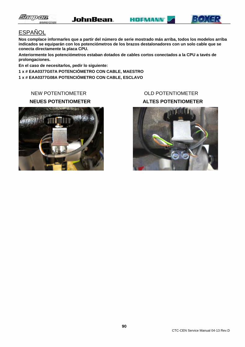
CTC-CEN Service Manual 04-13 Rev.D
90
ESPAÑOL Nos complace informarles que a partir del número de serie mostrado más arriba, todos los modelos arriba indicados se equiparán con los potenciómetros de los brazos destalonadores con un solo cable que se conecta directamente la placa CPU.
Anteriormente los potenciómetros estaban dotados de cables cortos conectados a la CPU a tavés de prolongaciones.
En el caso de necesitarlos, pedir lo siguiente:
1 x # EAA0377G07A POTENCIÓMETRO CON CABLE, MAESTRO
1 x # EAA0377G08A POTENCIÓMETRO CON CABLE, ESCLAVO
NEW POTENTIOMETER OLD POTENTIOMETER
NEUES POTENTIOMETER ALTES POTENTIOMETER

CTC-CEN Service Manual 04-13 Rev.D
91
Service-Bulletin No. SB 896 TC 18-Oct-12
Models affected: ATC 900, Centaur, monty 8600, Vulcan Pro
Starting from s/n: EEWH742AE.13
Subject: New bead breaker discs – Neue Abdrückscheiben
ENGLISH
Starting from the serial number reported above, all the listed tire changers are equipped by the new bead breaker discs.
The new bead breaker discs shape improves the stability of the discs themselves on very soft tires, avoiding possible slippage of the discs over the tire sidewall during the operation.
The former bead breaker discs will be no longer available. Since new and old discs are not interchangeable each other and cannot work together, in case of replacement of the former disc with the new one you have to order the following assemblies:
1 x # EAA0371G67A ASSY LOWER FULL DISK
1 x # EAA0371G66A ASSY UPPER FULL DISK
To replace the discs follow the next steps:
1. Remove the cylinder protection.
2. Remove the front screw.
3. Disconnect the air pressure from the machine.

CTC-CEN Service Manual 04-13 Rev.D
92
4. Push off the pin.
5. Remove the snap ring from the pin.
6. Push off the pin to remove the bead breaker disc assembly from the arm.
7. Mount the new bead breaker disc assembly on the arm and secure it with the snap ring.
8. Fix the bead breaker disc to the cylinder and secure the pin with the screw.
9. Connect the air pressure to the machine.
10. Adjust the disc inclination following paragraph 8.6 of the dedicated Service Manual.
11. Check if the machine works fine.

CTC-CEN Service Manual 04-13 Rev.D
93
DEUTSCH
Ab der oben angegebenen Seriennummer werden alle aufgeführten Reifenmontiermaschinen mit den neuen Abdrückscheiben ausgestattet.
Die Form der neuen Abdrückscheiben verbessert die Stabilität der Scheiben bei sehr weichen Reifen und vermeidet ein mögliches Abrutschen der Scheiben auf der Reifenseitenwand.
Die alten Abdrückscheiben sind nicht mehr lieferbar. Da alte und neue Scheiben nicht gegeneinander austauschbar sind und nicht zusammen benutzt werden können, sind bei einem Austauschen der alten gegen neue Abdrückscheiben folgende Baugruppen zu bestellen.
1 x # EAA0371G67A untere Abdrückscheibe kpl.
1 x # EAA0371G66A obere Abdrückscheibe kpl.
Die Abdrückscheiben sind wie folgt auszutauschen:
1. Die Zylinderabdeckung abnehmen
2. Die vordere Schraube herausdrehen.
3. Die Maschine von der Druckluftversorgung trennen.
4. Den Stift heraustreiben

CTC-CEN Service Manual 04-13 Rev.D
94
5. Den Sicherungsring vom Stift abnehmen
6. Den Stift ganz herausdrücken, um die komplette Abdrückscheibe vom Arm abnehmen zu können.
7. Die neue Abdrückscheibe am Arm montieren und mit dem Sicherungsring sichern.
8. Die Abdrückscheibe am Zylinder befestigen und den Stift mit der Schraube sichern.
9. Die Maschine wieder an die Druckluftversorgung anschließen.
10. Den Neigungswinkel der Abdrückscheibe gemäß Kapitel 8.6 des Servicehandbuches einstellen.
11. Prüfen, dass die Maschine ordnungsgemäß funktioniert.

CTC-CEN Service Manual 04-13 Rev.D
95
ITALIANO A partire dal numero di serie sopra riportato, tutti I modelli di smonatgomme elencati sono equipaggiati con nuovi dischi stallonatori.
La forma dei nuovi dischi stallonatore migliora la stabilità dei dischi stessi sugli pneumatici molto soffici, evitando possibili scivolamenti dei dischi sui fianchi degli pneumatici durante le operazioni.
I precedenti dischi stallonatori non saranno più disponibili. Siccome vecchi e nuovi dischi non sono intercambiabili fra loro e non possono lavorare insieme, in caso di sostituzione di un disco vecchio con uno nuovo dovrete ordinare i seguenti gruppi:
1 x # EAA0371G67A GRUPPO DISCO COMPLETO INFERIORE
1 x # EAA0371G66A GRUPPO DISCO COMPLETO SUPERIORE
Per sostituire i dischi seguire i seguenti passi:
1. Rimuovere la protezione cilindro.
2. Rimuovere la vite anteriore.
3. Scollegare l’aria compressa dalla macchina.
4. Spingere fuori il perno.
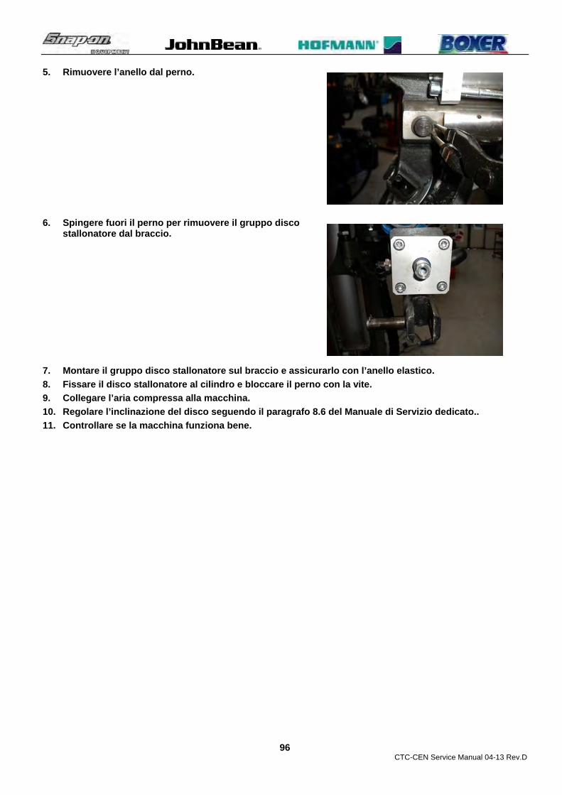
CTC-CEN Service Manual 04-13 Rev.D
96
5. Rimuovere l’anello dal perno.
6. Spingere fuori il perno per rimuovere il gruppo disco stallonatore dal braccio.
7. Montare il gruppo disco stallonatore sul braccio e assicurarlo con l’anello elastico.
8. Fissare il disco stallonatore al cilindro e bloccare il perno con la vite.
9. Collegare l’aria compressa alla macchina.
10. Regolare l’inclinazione del disco seguendo il paragrafo 8.6 del Manuale di Servizio dedicato..
11. Controllare se la macchina funziona bene.

CTC-CEN Service Manual 04-13 Rev.D
97
ESPAÑOL A partir del número de serie arriba mostrado, todos los modelos de desmontadoras de ruedas indicados, estarán equipados con un nuevo disco destalonador.
La forma del nuevo disco destalonador mejora la estabilidad del disco en neumáticos con talones muy blandos, evitando de esta forma posibles deslizamientos de este sobre el talón del neumático durante la operación de destalonamiento.
El anterior disco destalonador no continuará estando disponible. A partir que tanto el viejo como el nuevo disco destalonador no pueden ser intercambiables entre ellos y no pueden trabajar juntos, en caso de sustitución de un disco viejo por uno nuevo se debe pedir el siguiente grupo:
1 x # EAA0371G67A GRUPO DISCO COMPLETO INFERIOR
1 x # EAA0371G66A GRUPO DISCO COMPLETO SUPERIOR
Para sustituir el disco seguir los siguientes pasos:
1. Quitar la protección del cilindro.
2. Quitar el tornillo frontal.
3. Desconectar el aire comprimido de la máquina.
4. Retirar el perno.

CTC-CEN Service Manual 04-13 Rev.D
98
5. Quitar el segger del perno.
6. Retirar el perno para retirar el grupo del disco destalonador del brazo.
7. Montar el grupo disco destalonador en el brazo y fijarlo con el segger.
8. Fijar el disco destalonador al cilindro y apretar el tornillo.
9. Conectar la máquina al aire comprimido.
10. Regular la inclinación del disco siguiendo el capítulo 8.6 del Manual de Servicio.
11. Comprobar el funcionamiento correcto de la máquina.

CTC-CEN Service Manual 04-13 Rev.D
99
FRANÇAIS A partir du numéro de série reporté ci-dessus, tous les modèles de démonte-pneus cités sont équipés de nouveaux disques détalonneurs.
Les nouveaux disques détalonneurs ont une forme qui améliore leur stabilité en particulier sur les pneus très souples, de manière à éviter qu’ils ne glissent sur les flancs des pneus au cours des opérations.
Les disques détalonneurs précédents ne seront plus disponibles. Etant donné que les anciens et les nouveaux disques ne sont pas interchangeables et ne peuvent pas travailler ensemble, en cas de remplacement d’un disque ancien par un neuf, vous devrez commander les groupes suivants :
1 x # EAA0371G67A GROUPE DISQUE COMPLET INFERIEUR
1 x # EAA0371G66A GROUPE DISQUE COMPLET SUPERIEUR
Pour remplacer les disques, suivre les pas suivants :
1. Déposer la protection du vérin.
2. Retirer la vis avant.
3. Débrancher l’air comprimé de la machine.
4. Extraire la broche.

CTC-CEN Service Manual 04-13 Rev.D
100
5. Retirer la bague de la broche.
6. Extraire la broche pour retirer le groupe disque détalonneur du bras.
7. Monter le groupe disque détalonneur sur le bras et l’assurer avec une bague élastique.
8. Fixer le disque détalonneur au vérin et bloquer la broche avec la vis.
9. Raccorder l’air comprimé à la machine.
10. Régler l’inclinaison du disque en suivant les instructions rubr. 8.6 du Manuel de Service dédié.
11. Contrôler si la machine fonctionne correctement.

CTC-CEN Service Manual 04-13 Rev.D
101
Service-Bulletin No. SB 921 TC 24-Jan-13
Models affected: monty 8600 – John Bean Centaur – Boxer Vulcan Pro – ATC900
Starting from s/n:
Subject: Procedure to adjust bead breaker disks alignment – Ausrichtung der Abdrückscheiben
ENGLISH
In case of complaints related to bead breaker disks misalignment out of the maximum tolerance allowed, 1mm/0,04”, we would like to inform you that it is now available the following procedure to correct the output analog value of the potentiometer/s improving the bead breaker disks alignment accuracy.
PROCEDURE:
15. Fix to the multimeter terminals two small crocodiles style ones. 16. Remove the cover from the bead breaker arm potentiometer. 17. Select the multimeter in Vdc.
18. Position the red crocodile to the green wire and the black one on the white wire of the potentiometer.
19. Turn the machine on. 20. Move the bead breaker arms to maximum error
point.
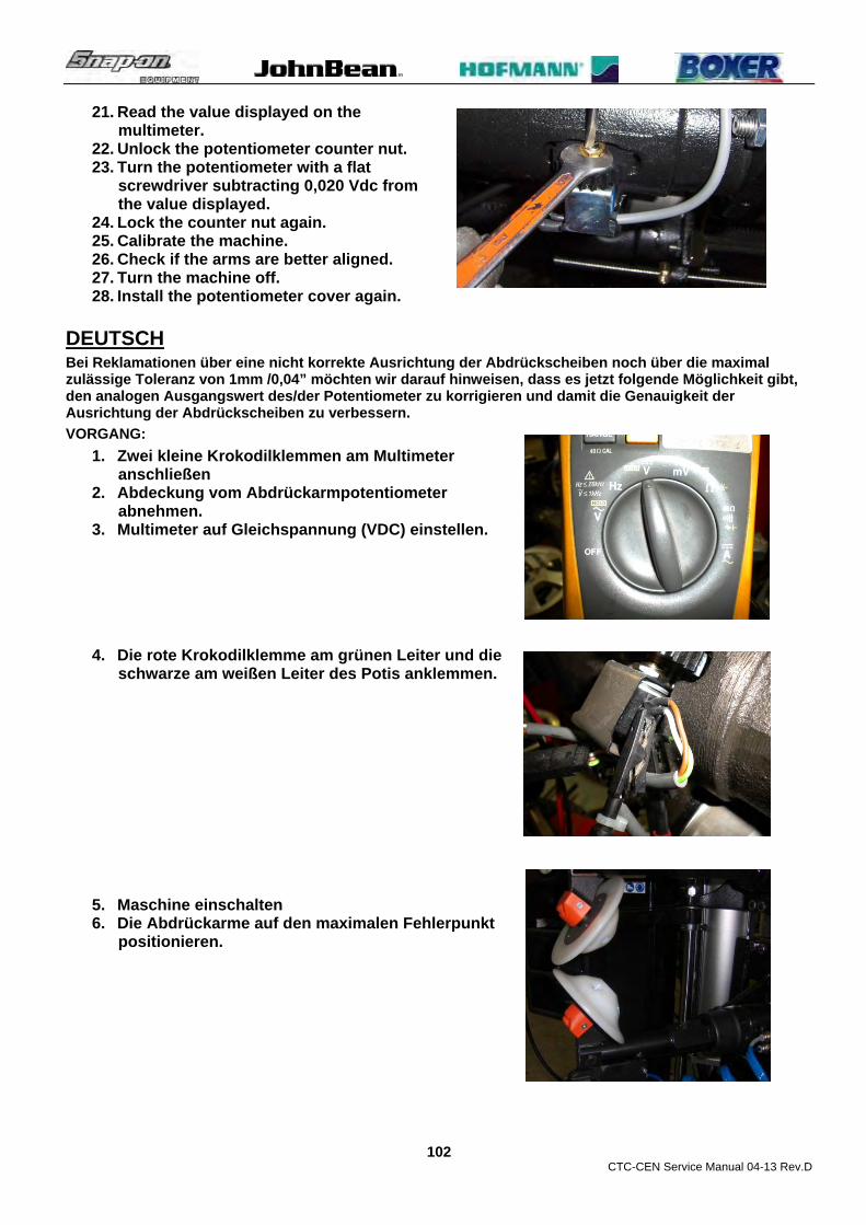
CTC-CEN Service Manual 04-13 Rev.D
102
21. Read the value displayed on the multimeter.
22. Unlock the potentiometer counter nut. 23. Turn the potentiometer with a flat
screwdriver subtracting 0,020 Vdc from the value displayed.
24. Lock the counter nut again. 25. Calibrate the machine. 26. Check if the arms are better aligned. 27. Turn the machine off. 28. Install the potentiometer cover again.
DEUTSCH
Bei Reklamationen über eine nicht korrekte Ausrichtung der Abdrückscheiben noch über die maximal zulässige Toleranz von 1mm /0,04” möchten wir darauf hinweisen, dass es jetzt folgende Möglichkeit gibt, den analogen Ausgangswert des/der Potentiometer zu korrigieren und damit die Genauigkeit der Ausrichtung der Abdrückscheiben zu verbessern.
VORGANG:
1. Zwei kleine Krokodilklemmen am Multimeter anschließen
2. Abdeckung vom Abdrückarmpotentiometer abnehmen.
3. Multimeter auf Gleichspannung (VDC) einstellen.
4. Die rote Krokodilklemme am grünen Leiter und die schwarze am weißen Leiter des Potis anklemmen.
5. Maschine einschalten 6. Die Abdrückarme auf den maximalen Fehlerpunkt
positionieren.

CTC-CEN Service Manual 04-13 Rev.D
103
7. Wert am Multimeter ablesen 8. Die Kontermutter am Poti lösen 9. Poti mit einem flachen Schraubendreher
auf den Anzeigewert minus 0,020 VDC einstellen
10. Kontermutter wieder kontern. 11. Maschine justieren 12. Prüfen, ob die Arme besser ausgerichtet
sind 13. Maschine ausschalten. 14. Potentiometer-Abdeckung wieder
anbringen.
ITALIANO In caso di lamentele relative al disallineamento dei dischi stallonatori fuori dalla tolleranza massima, 1mm/0,04”, gradiamo informarvi che è ora disponibile un una procedura per correggere il valore analogico in uscita del potenziometro/i migliorando la precisione dell’allineamento dei dischi stallonatori.
PROCEDURA:
1. Fissare ai terminale del multimetro due piccoli terminali a coccodrillo. 2. Remuovere la protezione del potenziometro stallonatore. 3. Selezionare Vdc sul multimetro.
4. Posizionare il coccodrillo rosso sul cavo verde e quello nero sul cavo bianco del potenziometro.
5. Accender la macchina. 6. Posizionarsi con i due stallonatori nel punto di
massimo errore.

CTC-CEN Service Manual 04-13 Rev.D
104
7. Allentare il dado di bloccaggio ruota dentata/albero del potenziometro superiore.
8. Con un cacciavite ruotare l’albero potenziometro togliendo 0,020 Volt al valore di riferimento.
9. Bloccare il controdado ancora. 10. Calibrare la macchina. 11. Verificare se i bracci stallonatori sono
allineati meglio. 12. Spegnere la macchina. 13. Installare la protezione potenziometro.
ESPAÑOL
En caso de queja relativa a la desalineación de los discos destalonadores fuera de la tolerancia máxima, 1mm/0.04”, nos complace informarles que hay disponible un nuevo procedimiento para corregir el valor analógico de salida del potenciómetro para mejorar la precisión de la alineación de los discos destalonadores.
PROCEDIMIENTO:
1. Instalar a los terminales del tester dos terminales pequeños del tipo cocodrilo. 2. Quitar la protección del potenciómetro del destalonador. 3. Seleccionar en el tester Vdc.
4. Colocar el cocodrilo rojo en el cable verde, y el negro en el cable blanco del potenciómetro.
5. Encender la máquina. 6. Posicionar los dos destalonadores en el punto de
máximo error.

CTC-CEN Service Manual 04-13 Rev.D
105
7. Aflojar la tuerca dentada del potenciómetro superior.
8. Con un destornillador girar el tornillo del potenciómetro quitando 0.020 voltios al valor de referencia.
9. Fijarlo y controlarlo ahora.. 10. Calibrar la máquina. 11. Verificar si los brazos destalonadores están
ahora mejor nivelados. 12. Apagar la máquina. 13. Instalar la protección del potenciómetro.
FRANÇAIS
Dans le cas de réclamations portant sur le désalignement des disques de déjantage hors de la tolérance maximale, 1mm/0,04”, nous souhaitons vous informer qu’il existe maintenant une procédure pour corriger la valeur analogique à la sortie du ou des potentiomètre/s ce qui améliore la précision de l'alignement des disques de déjantage.
PROCEDURE :
1. Raccorder les deux pinces crocodiles au multimètre.
2. Déposer le protecteur du potentiomètre du détalonneur.
3. Sélectionner Vdc sur le multimètre.
4. Placer la pince crocodile sur le câble vert et la noire sur le câble blanc du potentiomètre.
5. Mettre la machine en marche. 6. Se placer avec les deux détalonneurs au point
d’erreur maximale.

CTC-CEN Service Manual 04-13 Rev.D
106
7. Desserrer l’écrou de blocage roue dentée/arbre du potentiomètre supérieur.
8. Avec un tournevis, tourner l’arbre potentiomètre en soustrayant 0,020 Volt à la valeur de référence.
9. Bloquer le contre-écrou du serrage. 10. Calibrer la machine. 11. Vérifier si les détalonneurs sont mieux
alignés. 12. Eteindre la machine. 13. Remettre en place le protecteur du
potentiomètre.
RUSSIAN
В отношении жалоб на несоосность дисков разбортовочного устройства сверх допуска (1 мм) мы сообщаем, что теперь есть возможность проведения следующей процедуры по исправлению аналогового значения потенциометра на выходе, что повышает точность центрирования дисков разбортовочного устройства.
ПРОЦЕДУРА:
1. Установить на клеммах универсального измерительного прибора два небольших зажима типа «крокодил».
2. Снять крышку с потенциометра на рычаге разбортовочного устройства.
3. Установить напряжение постоянного тока на универсальном измерительном приборе.
4. Разместить красный «крокодил» на зеленом проводе, а черный - на белом проводе потенциометра.
5. Включить установку. 6. Переместить два рычага в точку максимальной
погрешности.

CTC-CEN Service Manual 04-13 Rev.D
107
7. Снять показание на дисплее универсального измерительного прибора.
8. Ослабить контргайку зубчатого колеса/вала верхнего потенциометра.
9. Используя отвертку, повернуть вал потенциометра, уменьшив значение на 0,020 В относительно отображаемого на дисплее.
10. Снова застопорить контргайку. 11. Выполнить калибровку установки. 12. Проверить, изменилось ли центрирование рычагов. 13. Выключить установку. 14. Вернуть на место крышку потенциометра.

CTC-CEN Service Manual 04-13 Rev.D
108
Service-Bulletin No. SB 929 TC 25-Feb-13
Models affected: Passenger tire changer with tire inflator and KPa manometer
Starting from s/n:
Subject: KPa Wika manometer 0031373 accuracy
ENGLISH Following up some cases of Wika manometer # 0031373 replaced under warranty due to inaccurate tire pressure reading, we would like to inform you that the manometer is 2.5 class and its homologated tolerance is +/- 25KPa on all pressures measured.
Example:
200KPa -> +/-25KPa
300KPa -> +/-25KPa
400KPa -> +/-25KPa
Please take good note that if the manometer shows the tire pressure within these tolerances and if its arrow returns to zero after disconnecting the inflating hose from the wheel, it does not have to be replaced.
In case the manometer will not return to zero, before replacing it we recommend to remove the rear sintered air filter absorber # 0019181, shown in the picture, and make sure that the manometer will return to zero. If the manometer will return to zero replace the sintered air filter absorber # 0019181.
The replaced manometers under warranty due to low accuracy will be inspected and if they will show pressure within the homologated tolerances, we will be forced to invoice them.
DEUTSCH Nachdem einige Wika-Manometer # 0023484 aufgrund ungenauer Reifendruckanzeige unter Gewährleistung ausgetauscht wurden, möchten wir hier nochmals auf die geprüfte Genauigkeit des Manometers aufmerksam machen:
Bitte beachten, wenn die Druckanzeige des Manometers innerhalb dieser Toleranzen liegt und der Zeiger nach dem Abnehmen des Füllschlauches vom Rad wieder in Nulllage zurückkehrt, muss das Manometer nicht ausgetauscht werden.
Falls der Zeiger nicht in Nulllage zurückkehrt, empfehlen wir – wie im Bild gezeigt – vor Austausch des Manometers noch den hinteren Luftfilter # 0019181 abzunehmen und zu prüfen, ob der Zeiger dann in Nulllage zurückkehrt. Falls dies geschieht, den Luftfilter # 0019181 auswechseln.
Manometer, die aufgrund ungenügender Genauigkeit unter Gewährleistung ausgetauscht werden, werden im Werk überprüft. Falls es sich zeigt, dass die Druckanzeige innerhalb der geprüften Toleranzen liegt, müssen wir das Teil leider in Rechnung stellen.
Example:
200KPa -> +/-25KPa
300KPa -> +/-25KPa
400KPa -> +/-25KPa

CTC-CEN Service Manual 04-13 Rev.D
109
ITALIANO A seguito di alcuni casi di manometri Wika # 0031373 sostituiti in garanzia a seguito della lettura imprecisa della pressione degli pneumatici, gradiamo informarvi che questo manometro è in classe 2.5 ed la sua tolleranza omologata è di +/- 25 KPa su tutte le pressioni misurate.
Prego prendere ben nota che se il manometro mostra la pressione degli pneumatici entro queste tolleranze e se la sua lancetta ritorna a zero dopo aver staccato il tubo di gonfiaggio dalla ruota, non deve essere sostituito.
Nel caso in cui il manometro non ritorni a zero, prima di sostituirlo raccomandiamo di scollegare il filtro sinterizzato smorzatore posteriore # 0019181, mostrato in figura, e assicuratevi che il manometro ritorni a zero. Se il manometro non ritorna a zero sostituite il filtro sinterizzato smorzatore # 0019181.
I manometri sostituiti in garanzia per mancata accuratezza verranno controllati al rientro e, se trovati nelle tolleranze omologate, saremo costretti a fatturarli.
Esempi:
200KPa -> +/-25KPa
300KPa -> +/-25KPa
400KPa -> +/-25KPa
ESPAÑOL Después de algunos casos de manómetros Wika # 0023484 sustituidos en garantía por causa de una lectura imprecisa de la presión del neumático, nos complace informarles que la precisión homologada del manómetro es la siguiente:
Pido tomar buena nota de que si el manómetro muestra la presión del neumático entre estas tolerancias y la aguja retorna a cero después de quitar el tubo de inflado de la rueda, no debe ser sustituido.
En el caso en que el manómetro no vuelve a cero, antes de sustituirlo recomendamos desconectar el filtro absorvente posterior # 0019181, mostrado en la figura, y asegurarse que el manómetro vuelve a cero. Si el manómetro vuelve a cero sustituir el filtro absorvente posterior # 0019181.
El manómetro sustituido en garantía por falta de precisión se comprobarán al retorno, y si se comprueba la tolerancia homologada, nos veremos obligados a cobrarlo.
Example:
200KPa -> +/-25KPa
300KPa -> +/-25KPa
400KPa -> +/-25KPa
FRANÇAIS Après avoir dû remplacé des manomètres Wika # 0023484 sous garantie qui avaient comme défaut une mesure imprécise de la pression des pneus, nous souhaitons vous informer que la précision homologuée du manomètre est la suivante :
Prière de prendre bien note que si le manomètre indique une pression des pneus dans les limites de ces tolérances et si l’aiguille retourne à zéro après avoir débranché le tube de gonflage de la roue, il ne doit pas être remplacé.
Dans le cas où le manomètre ne retournerait pas à zéro, avant de le remplacer, nous recommandons de débrancher le filtre synthérisé arrière # 0019181, illustré dans la figure, et s’assurer que le manomètre retourne à zéro. Si le manomètre ne retourne pas à zéro, remplacez le filtre synthérisé # 0019181.
Les manomètres remplacés sous garantie parce qu’ils ont un défaut de précision seront contrôlés à leur retour en usine et s’ils rentrent dans les tolérances homologuées, nous serons dans l’obligation de les facturer.
Example:
200KPa -> +/-25KPa

CTC-CEN Service Manual 04-13 Rev.D
110
300KPa -> +/-25KPa
400KPa -> +/-25KPa

CTC-CEN Service Manual 04-13 Rev.D
111
UPDATING GUIDE: REVISION A – July 2012 ________________________________________________________________________________________ REVISION B – July 2012 Updated parts of chapters : 7.12 Bead breaker cylinders and discs valves: # EAA0350G58A / EAA0377G25A: check and replacement (Text) Pag. 45 7.14 Bead breaker arms valve blocking # EAA0377G26A: check and replacement (Text) Pag. 49 8.2 Automatic tool # EAA0356G25A: check, replacement and adjustment (Pictures) Pag. 63 8.6 Bead breaker discs inclination alignment: check and adjustment (Pictures) Pag. 70 9 TROUBLE SHOOTING (text) Page. 75
REVISION C – January 2013 Updated parts of chapters : 5.2 Main rotary switch Q1 # 2-15359A: Check and replacement (Text) Pag. 14 6.3 Bead breaker arms potentiometers B1 and B2 # EAA0377G07A:
Check and replacement (Text). Pag. 23 6.4 Procedure to adjust the bead breaker disks alignment (New) Pag. 28 6.5 Bead breaker arms calibration SW 1.0.3 / 1.0.4 (Text) Pag. 29 7.9 Automatic tool cylinder # EAA0363G81A: Check and replacement (Text) Pag. 41 7.15 Wheel lift cylinder # EAA0344G93A: Check and replacement (Text) Pag. 50 8.1 Opening arm bushings # 1-10065a: Check and replacement (Text) Pag. 58 8.3 Horizontal arm rollers # EAA0347G76A: Check and adjustment (Text) Pag. 68 8.4 Gear box: Check and replacement (Text) Pag. 68 8.5 Bead breaker discs # EAM0065G63A: Check and replacement (Text) Pag. 70 8.6 Bead breaker discs # EAM0065G63A: Check and replacement (New) Pag. 71 8.7 Bead breaker discs bearing # 1-06963A: Check and replacement (New) Pag. 72 8.8 Bead breaker discs inclination adjustment. (Text) Pag. 73 8.9 Bead breaker discs clearance: Check and adjustment (Text) Pag. 74 8.10 Bead breaker carriage: Check and adjustment (Text) Pag. 76 8.11 Lead screw nut # EAM0076G10A: Check and adjustment (Text) Pag. 76 10 Service Bulletins (New) Pag. 81 REVISION D – April 2013 2.1 Tools and Special tools (Update) Pag. 5 6.2 Inverter T1 # EAA0358G49A: Firmware update (New) Pag. 25

AUTHOR: Stefano Muzzioli
Copyright statement This manual and the materials contained within are copyright protected. The manual, or any section, page, drawing, or diagram, may not be reproduced by any means without the written consent. The information and specifications in this manual are based on the latest information available at the time of publication. We reserve the right to change the specifications at any time without notice.
Snap-on Equipment Srl unipersonale
Via Provinciale per Carpi, 33 42015 CORREGGIO (RE) ITALY Tel. +39-(0)522-733489 Fax +39-(0)522-733610 E-mail: [email protected] Internet: http://www. snapon-equipment.eu
Copyright © 2013 Snap-on Equipment - All Rights Reserved -
Rev.D April 2013 gft... P/N: TEEWh542A1
SO
E D
igita
l Co
de:
SM
_CT
C-C
EN
_04
-13_
TE
EW
H54
2A1_
RD