asynchronous transmission
84
Topic 4.5.5 – Asynchronous Transmission Learning Objectives: At the end of this topic you will be able to; describe asynchronous character framing in terms of the start and stop bits, data bits and parity bit; appreciate that the ability to detect and correct errors that occur during digital transmissions is not possible with analogue systems; describe how using extra parity bits can provide error detection and correction; describe and use two-bit parity-bit systems to speed up data transfer by only having to retransmit half of the data when an error is detected describe and use a five parity-bit system to identify and correct a single error if it has occurred; realise that even with multiple parity-bit systems it is not always possible to detect and correct errors when more than one bit is affected; appreciate that there is a trade off between the ability to check and correct data and the extra transmission costs; realise that in very noisy or sensitive applications it is often essential to have a high level of data checking despite the extra cost involved. 1
description
data transmission
Transcript of asynchronous transmission

Topic 4.5.5 – Asynchronous Transmission
Learning Objectives:
At the end of this topic you will be able to;
describe asynchronous character framing in terms of the start and stop bits, data bits and parity bit;
appreciate that the ability to detect and correct errors that occur during digital transmissions is not possible with analogue systems;
describe how using extra parity bits can provide error detection and correction;
describe and use two-bit parity-bit systems to speed up data transfer by only having to retransmit half of the data when an error is detected
describe and use a five parity-bit system to identify and correct a single error if it has occurred;
realise that even with multiple parity-bit systems it is not always possible to detect and correct errors when more than one bit is affected;
appreciate that there is a trade off between the ability to check and correct data and the extra transmission costs;
realise that in very noisy or sensitive applications it is often essential to have a high level of data checking despite the extra cost involved.
1
Module ET4 – Communication Systems
Computer Communications.
For humans to communicate with each other so that all of the message is understood they must use the same language. For electronic systems to communicate effectively with one another is should be obvious that they must also use the same language and systems to communicate with each other.
There are currently two main methods used for data communication as shown below:
a. Serial – i.e. one bit at a time.b. Parallel – i.e. the whole 8 bits at the same time.
Within each of these two categories we could send the data using one of two systems
i. Synchronouslyii. Asynchronously
In the time available for this course it would be impossible to look at all of these various systems in detail, as this is a major subject in its own right. For this course we will concentrate on Asynchronous Serial Communication. The purpose of this topic is to give a flavour of the issues that exist in the transfer of data from one system to another. Students are empowered to carryout further research into other methods if they are so inclined, however these will not be examined.
Synchronous and Asynchronous Serial Communications.
In this module we will concentrate on Asynchronous Serial Transmission but we will take a very brief look at synchronous communication first.
For electronic systems to communicate they must exchange data at the same rate using the same voltage levels. Unless the two systems remain synchronised, data can become corrupted and may have serious consequences.
Synchronous Serial Communication.
Two synchronous serial communications systems are dealt with in this module. One system involves PCM / TDM which uses a channel(s) to
2

Topic 4.5.5 – Asynchronous Transmission
maintain synchronisation which is dealt with in another part of this unit (Topic 4.5.4).
Here we will consider a simple non-multiplexed system that can be used for direct communication between two units. In this example of synchronous transfer the two units that are communicating with each other are physically linked by a data and clock line. This is shown below.
The common clock line keeps the two units synchronised and controls the rate at which data is being sent and also tells the receiver when to read the data. A single clock signal controls both units.
During a period where no data is being transferred, usually referred to as the ‘idle’ period, the clock line is kept at logic 0. When data is ready to be transmitted the clock line goes high (logic 1) to signal the start of data transfer.
The falling edge of the clock pulse is used by the receiver to read the data present on the data lines. This small delay allows the data line to stabilise at its true logic value and ensures that the correct data is read.
The main advantage of using synchronous serial communication is that the transmitter has control over the speed of data transfer and is able to vary the rate if problems occur. The disadvantage is the need to have an extra link between transmitter and receiver, i.e. the clock line.
Asynchronous Serial Transmission.
3

Module ET4 – Communication Systems
In asynchronous serial transmission there is no link between the clock signals of transmitter and receiver. There has to be agreement between the transmitter and receiver about clock frequencies and there are a number of agreed international frequencies that can be used.
Communication is established by adding extra signals to the data before it is transmitted. These extra signals appear as two additional ‘bits’ of data, a start bit, and a stop bit.
Note : In practical systems it is common practice to reverse data bits before transmission so that D7 is the first data bit to appear on the transmission line after the start bit, D0 is the last.
The data line is held at logic 1 when it is ‘idle’ or has no data to transmit. When it is ready to send data the data line drops from logic 1 to logic 0. This is the start bit. The following eight bits correspond to the data to be transmitted. This is then followed by a logic 1 bit – called the stop bit which signals the end of the transmission.
The clock of the receiver is started half a cycle after the data line drops to logic 0. The receiver reads the next eight bits of data. When the data bits have been transmitted the transmitter sends the logic 1 stop bit, which returns the data line to its idle state. The receiver then stops its clock and returns to a waiting state, ready for the next time the data line receives a start signal by moving to logic 0.
As the data is read during the middle of a bit, slight variations in clock frequency are unlikely to result in data corruption over this short period of time – just 10 clock cycles. Typically a variation between transmitter and receiver clock periods of up to 5% is acceptable.
Using this system, the addition of the two extra control bits, means that for every byte of information to be sent between the transmitter and receiver requires ten clock cycles to complete the transfer. Asynchronous communication links are therefore slower than
4
Data 'idle'
D0 D DD D D D D1 2 3 4 5 6 7
at logic 1
Start Bit Stop Bit'idle'
at logic 1
D7 D6 D5 D4 D3 D2 D1 D0

Topic 4.5.5 – Asynchronous Transmission
synchronous systems. However it is the preferred communication system between PC’s, because of the saving on having to have fewer cable connection costs between systems.
This system does still have a major drawback, from the point of data integrity as there is no feedback between the data sent and the data received. It is possible that during transmission external electrical interference on the signal may cause the data bits to become corrupted. The receiver may be completely unaware that the data has changed during transmission and accept the incoming, ‘corrupted’ data as being valid.
If this error is the code for a single letter in a big newspaper article then any corruption may be considered trivial as the only likely outcome will be the appearance of an incorrect letter in a word. This might be simply ignored and put down to a typing error at the source.
However if the error occurs in the code being sent to the launch control of a nuclear missile, clearly the consequences of misinterpretation of this code are much more significant, as it could be the difference between whether to launch or not, or change the target if it is part of the navigation control of the missile.
5
Module ET4 – Communication Systems
It is for this reason that extra ‘bits’ are added to data transmissions, to allow some form of error checking to take place. This extra bit is called a ‘Parity Bit’ and it is included between the eight data bits and the stop bit as shown below.
The Parity bit can either be a logic 1 or 0 and depends upon the data within the byte, and the parity convention that is being used.
Parity can be defined as either ‘even’ or ‘odd’. In an even parity system the logic state of the parity bit is set so that the number of logic 1’s in the byte and the parity bit are an ‘even’ number.
We will now consider a number of examples to see how this parity bit can be used.
6
Data 'idle'
D0 D DD D D D D1 2 3 4 5 6 7
at logic 1
Start BitStop
'idle'at logic 1
ParityBit
Bit
D7 D6 D5 D4 D3 D2 D1 D0

Topic 4.5.5 – Asynchronous Transmission
Examples of even parity:
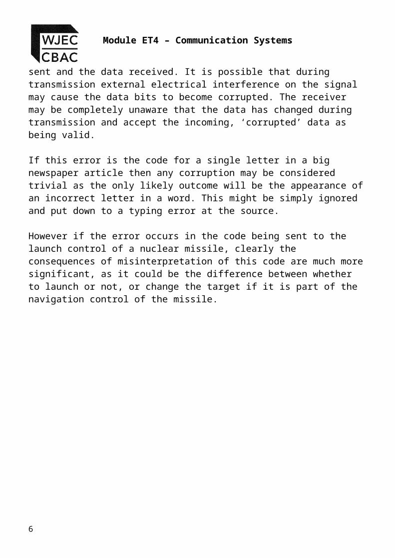
1. The data 1 0 1 1 0 0 1 0 is to be transmitted using even parity. In this case there are ‘four’ logic 1’s in the data which is an even number, and therefore the parity bit would be set to logic 0. The complete data to be transmitted would therefore be as follows:
2. The data 1 0 0 0 1 0 1 0 is to be transmitted using even parity. In
this case there are only ‘three’ logic 1’s in the data which is an odd number, and therefore the parity bit would be set to logic 1. The complete data to be transmitted would therefore be as follows:
Systems using even parity are the most commonly found, but it is possible to have systems that employ ‘odd’ parity. These work in a similar way to ‘even’ parity systems except that the parity bit set to a logic level that makes the total number of logic 1’s in the data byte and parity bit to be an ‘odd’ number.
7

Module ET4 – Communication Systems
Examples of odd parity:
1. The data 1 0 1 1 0 0 1 0 is to be transmitted using odd parity. In this case there are ‘four’ logic 1’s in the data which is an even number, and therefore the parity bit would be set to logic 1. The complete data to be transmitted would therefore be as follows:
2. The data 1 0 0 0 1 0 1 0 is to be transmitted using odd parity. In
this case there are ‘three’ logic 1’s in the data which is an odd number, and therefore the parity bit would be set to logic 0. The complete data to be transmitted would therefore be as follows:
The receiving equipment checks each byte as it arrives with the status of the parity bit. If the number of 1’s in the data byte and parity bit correspond with the state of the parity bit the data is accepted as being valid. If they do not agree the data is rejected and a request is sent to the transmitter to resend the last piece of information. A simple form of error checking has been introduced.
8

Topic 4.5.5 – Asynchronous Transmission
Example :
The data 1 1 0 1 1 0 1 0 is to be transmitted using even parity. In this case there are ‘five’ logic 1’s in the data which is an odd number, and therefore the parity bit would be set to logic 1. The complete data to be transmitted would therefore be as follows:
Now let us assume that the following data has been received:
The data contains four logic 1’s and the parity bit is a Logic 1, making a total of five. This is an odd number and as the system is meant to be using even parity – the parity check fails and a control signal would be sent back to the transmitting device to resend this particular byte of data.
The single pit parity system appears to provide some confidence then that an error in the transmission can be detected.
9

Module ET4 – Communication Systems
Unfortunately closer examination of this error detection system reveals a subtle problem as illustrated in the following example:
The data 1 0 1 1 0 0 1 0 is to be transmitted using odd parity. In this case there are ‘four’ logic 1’s in the data which is an even number, and therefore the parity bit would be set to logic 1. The complete data to be transmitted would therefore be as follows:
Now let us imagine that the data received after transmission is as follows:
Now check the parity condition – 4 logic 1’s in the data bits + Logic 1 parity bit making a total of five – therefore a parity check passes! A careful examination of the data however will show that the data bits are not the same, so how did the parity test pass ?
Put simply the parity check is just a check on the number of Logic 1’s in the data – it cannot determine where the logic 1’s are. In this case two bits have become inverted, the total number of Logic 1’s is the same but they are in the wrong location.
10
Topic 4.5.5 – Asynchronous Transmission
ASCII Code
The American Standard Code for Information Interchange (ASCII) is the most commonly used alphanumeric (alphabetical and numerical) digital communication code used in micro-computer systems. Basic ASCII uses 7-bits and extended ASCII uses 8-bits. For this course we will only use the basic ASCII character set which uses 7-bits.
In order to provide a unique code for the 26 letters of the alphabet, in both upper and lower case, together with the numbers 0 – 9, and various punctuation marks and characters such as ‘, : ; . “ ( ) ^ * £ $, it is surprising to find that just 7 bits are required. Using 7 bits give a total number of possible different codes of 27 = 128 different possibilities. This is more than sufficient for the characters described above and even allows some spare for special codes for printers like ‘line feed’, ‘carriage return’ etc.
With only 7 bits required D7, is usually configured to be the parity bit where parity is used, and is just set to 0 when parity is not being used.
The following table shows a small portion of the ASCII code for some of the traditional keyboard characters. The full table can be viewed at http://www.neurophys.wisc.edu/comp/docs/ascii/
Character ASCII Code (Binary)
Character ASCII Code(Binary)
0 011 0000 A 100 0001
1 011 0001 B 100 0010
2 011 0010 a 110 0001
3 011 0011 b 110 0010
8 011 1000 X 101 1000
9 011 1001 z 111 1010
Note : You will not be required to remember any of these ASCII codes for the examination. If the use of an ASCII code will be required to answer a question then a subset of the table will be printed with the question concerned. We will now look at some past exam paper questions on this topic, so that you will understand what will be expected of you in the examination.
11
Module ET4 – Communication Systems
Example:The graph shows the waveform of a signal received at the serial port of a computer using even parity.
The signal carries the ASCII code for an alphanumeric character.
Logic 1
Logic 0time
Voltage
The signal includes
start and stop bits, a parity bit, and 7 data bits corresponding to the ASCII character.
i) Label the start bit and the parity bit.[2]
ii) Write down the 7 bit character code.[2]
.......................................................................................................................................
Solution :
i)
ii) The 7 data bits seem to be 1101100 (this would gain 1 mark), but remember these are reversed for transmission so the actual data transmitted is 0011011 (this would gain two marks).
12
Logic 1
Logic 0time
VoltageStart Bit (1 mark)
Parity Bit (1 mark)

Topic 4.5.5 – Asynchronous Transmission
Student Exercise 1:
Now try these yourself for practice:
1. The graph shows the waveform of a signal transmitted from a computer.
The signal carries the ASCII code for an alphanumeric character.
The signal includes a start bit and two stop bits, a parity bit, and 7 data bits corresponding to the ASCII character.
i) Label the start bit and the parity bit.[2]
ii) Write down the 7 bit character code.
..................................................................................................
........................[2]
iii) The system uses even parity. Use the graph to work out if the signal contains a single error.
..................................................................................................
........................[1]
iv) Explain how you obtained your answer to part (iii).
..................................................................................................
...........................
..................................................................................................
...........................
..................................................................................................
...........................
13

Module ET4 – Communication Systems
[1]
14
Topic 4.5.5 – Asynchronous Transmission
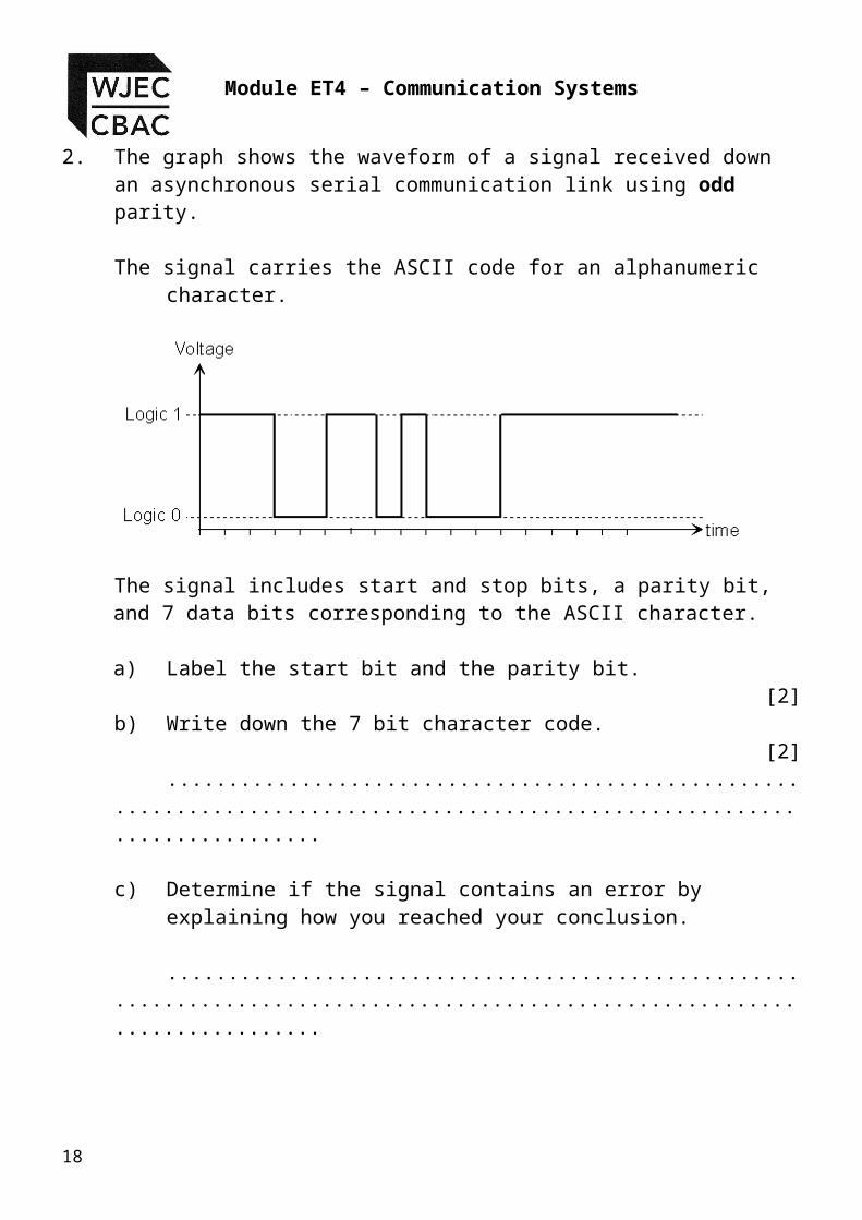
2. The graph shows the waveform of a signal received down an asynchronous serial communication link using odd parity.
The signal carries the ASCII code for an alphanumeric character.
The signal includes start and stop bits, a parity bit, and 7 data bits corresponding to the ASCII character.
a) Label the start bit and the parity bit.[2]
b) Write down the 7 bit character code.[2]
.............................................................................................................................
c) Determine if the signal contains an error by explaining how you reached your conclusion.
.............................................................................................................................
.............................................................................................................................
.............................................................................................................................
.............................................................................................................................
[1]
15

Module ET4 – Communication Systems
3. The ASCII code is an internationally agreed method of coding alphanumeric characters in computer systems.
The following table gives the ASCII code for a number of different characters.
Character ASCII Code
h 1101000k 1101011p 1110000y 1111001
a) Before transmission of data takes place, a parity bit is added to the 7 bit ASCII code. Explain the purpose of the parity bit.
[1]..........................................................................................................
............................. ..................................................................................
..................................................... ..........................................................
............................................................................. b) Complete the
following to show the logic state of the parity bit if:
i) Character “k” is transmitted using odd parity.
Parity Bit = ............
ii) Character “p” is transmitted using even parity.
Parity Bit = ............[2]
16
Topic 4.5.5 – Asynchronous Transmission
c) A transmission system uses odd parity. Start and stop bits are added before the signal is transmitted. Complete the following graph to show the waveform of the transmitted signal when the character “y” is transmitted.
Logic 1
Logic 0time
Voltage
[4]
Summary of the Single Bit Parity System
The single bit parity check can be used for the detection of single
errors only.
If the parity bit check fails then all of the transmitted data would
need to be sent again.
If two errors occur it is possible the parity check will pass.
Having to retransmit all eight bits can be seen as a disadvantage in this system and may add to the time taken to transmit a signal between two locations.
17
Module ET4 – Communication Systems
Multiple Bit Parity System
For these systems we will consider the data to be transmitted as an 8-bit word, rather than as characters from the ASCII character set to represent any form of data communication.
Two bit parity
A small improvement can be obtained by treating the 8 bit word (byte) as two separate 4 bit words (nibbles). In this system two parity bits are used, one for each nibble.
e.g
D7 D6 D5 D4 D3 D2 D1 D0 P1 P0
1 1 0 1 1 1 0 0 1 0
This example given here is using even parity but odd parity could also be used just as easily.
Advantages of the two bit parity system.
can detect two errors provided that there is one error in each nibble.
if only one error occurs then only half of the data needs to be resent, therefore speeding up the process of receiving the correct data.
Disadvantages of the two bit parity system.
Two errors in same nibble may still pass. An extra parity bit has to be transmitted for every byte in the message, this will take extra time to transmit the message even if no errors are detected.
No data correction is possible.Using the two-bit parity system we have gained a small advantage in the fact that when an error is detected only half of the data needs to be resent, however every byte that will be transmitted has an extra bit to send which will increase the transfer time anyway. What is really needed is the ability to detect an error and then correct the data at the receiver instead of having to request that this is resent from the transmitting machine.18
Topic 4.5.5 – Asynchronous Transmission
By using additional parity bits it is not only possible to detect an error, but also to identify which bit is actually incorrect so that it can be corrected at the receiver, without the need for retransmission. These are multiple parity bit systems
19

Module ET4 – Communication Systems
4-bit Parity Systems
By increasing the number of parity bits to four it is possible to not only detect a single error but also to correct it. The following diagram shows how the four parity bits are constructed from the original 8-bit word.
In this example the relevant bits have been taken out of the original to show how each parity bit is determined. An even parity system is being used here.
D7 D6 D5 D4 D3 D2 D1 D0 P3 P2 P1 P0
1 1 0 1 1 1 0 0 0 1 1 0
1 1 0 0 0
1 1 0 1 1
0 1 0 0 1
1 0 1 0 0
In this system the parity bits are assigned as follows:
Parity bit P0, checks the number of Logic 1’s in the data bits D0, D1, D2, and D3.
Parity bit P1, checks the number of Logic 1’s in the data bits D4, D5, D6, and D7.
Parity bit P2, checks the number of Logic 1’s in the data bits D0, D1, D4, and D5.
Parity bit P3, checks the number of Logic 1’s in the data bits D1, D2, D5, and D6.
20

Topic 4.5.5 – Asynchronous Transmission
In future and in examination questions the Data bits which are linked to each Parity Bit will be shown by a table like this.
D7 D6 D5 D4 D3 D2 D1 D0 P3 P2 P1 P0
1 1 0 1 1 1 0 0 0 1 1 0
x x x x x
x x x x x
x x x x x
x x x x x
Examples :
Complete the parity bits for the following examples:
1.
D7 D6 D5 D4 D3 D2 D1 D0 P3 P2 P1 P0
0 1 1 0 1 0 1 0
x x x x x
x x x x x
x x x x x
x x x x x
2.
D7 D6 D5 D4 D3 D2 D1 D0 P3 P2 P1 P0
1 0 1 0 0 1 0 1
x x x x x
x x x x x
x x x x x
x x x x x
Now that we understand how each parity bit is used we will consider what happens when errors occur to each bit in the data section during transmission. We will use the data as shown below as our example. Even parity is used for the transmission.
21

Module ET4 – Communication Systems
Original Data:
D7 D6 D5 D4 D3 D2 D1 D0 P3 P2 P1 P0
1 1 0 1 1 1 0 0 0 1 1 0
x x x x x
x x x x x
x x x x x
x x x x x
i) the effect of an error in D0.
D7 D6 D5 D4 D3 D2 D1 D0 P3 P2 P1 P0
1 1 0 1 1 1 0 1 0 1 1 0
x x x x x
x x x x x
x x x x x
x x x x x
D0 is inverted. P0 and P2 fail.The only data bit common to both P0 and P2 is D0, therefore it must be D0 which is incorrect.
22

Topic 4.5.5 – Asynchronous Transmission
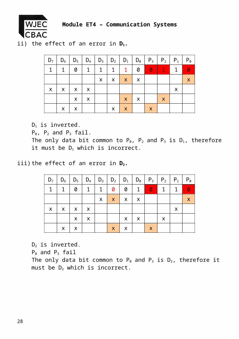
ii) the effect of an error in D1.
D7 D6 D5 D4 D3 D2 D1 D0 P3 P2 P1 P0
1 1 0 1 1 1 1 0 0 1 1 0
x x x x x
x x x x x
x x x x x
x x x x x
D1 is inverted.P0, P2 and P3 fail.The only data bit common to P0, P2 and P3 is D1, therefore it must be D1 which is incorrect.
iii) the effect of an error in D2.
D7 D6 D5 D4 D3 D2 D1 D0 P3 P2 P1 P0
1 1 0 1 1 0 0 1 0 1 1 0
x x x x x
x x x x x
x x x x x
x x x x x
D2 is inverted.P0 and P3 failThe only data bit common to P0 and P3 is D2, therefore it must be D2 which is incorrect.
23
Module ET4 – Communication Systems
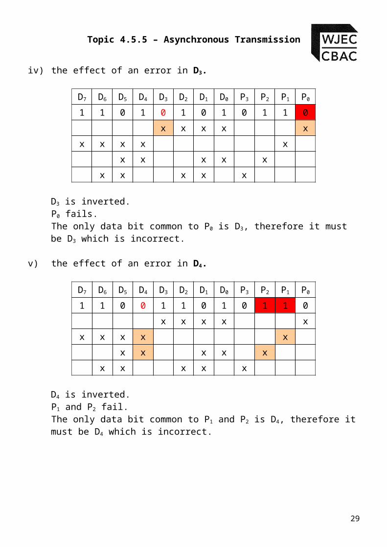
iv) the effect of an error in D3.
D7 D6 D5 D4 D3 D2 D1 D0 P3 P2 P1 P0
1 1 0 1 0 1 0 1 0 1 1 0
x x x x x
x x x x x
x x x x x
x x x x x
D3 is inverted.P0 fails.The only data bit common to P0 is D3, therefore it must be D3 which is incorrect.
v) the effect of an error in D4.
D7 D6 D5 D4 D3 D2 D1 D0 P3 P2 P1 P0
1 1 0 0 1 1 0 1 0 1 1 0
x x x x x
x x x x x
x x x x x
x x x x x
D4 is inverted.P1 and P2 fail. The only data bit common to P1 and P2 is D4, therefore it must be D4 which is incorrect.
24

Topic 4.5.5 – Asynchronous Transmission
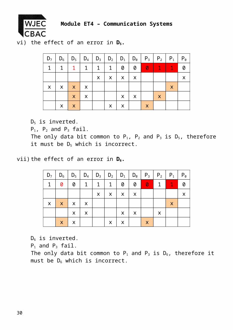
vi) the effect of an error in D5.
D7 D6 D5 D4 D3 D2 D1 D0 P3 P2 P1 P0
1 1 1 1 1 1 0 0 0 1 1 0
x x x x x
x x x x x
x x x x x
x x x x x
D5 is inverted.P1, P2 and P3 fail.The only data bit common to P1, P2 and P3 is D5, therefore it must be D5 which is incorrect.
vii) the effect of an error in D6.
D7 D6 D5 D4 D3 D2 D1 D0 P3 P2 P1 P0
1 0 0 1 1 1 0 0 0 1 1 0
x x x x x
x x x x x
x x x x x
x x x x x
D6 is inverted.P1 and P3 fail.The only data bit common to P1 and P3 is D6, therefore it must be D6 which is incorrect.
25

Module ET4 – Communication Systems
viii) the effect of an error in D7.
D7 D6 D5 D4 D3 D2 D1 D0 P3 P2 P1 P0
0 1 0 1 1 1 0 0 0 1 1 0
x x x x x
x x x x x
x x x x x
x x x x x
D7 is inverted.P1 fails.The only data bit common to P1 is D7, therefore it must be D7 which is incorrect.
The four bit parity system will therefore allow the correction of data bit errors as we have seen from the examples above. It might appear that we have solved a major problem of the single parity bit system, where data can be corrected at the receiver, and this is indeed true if the error is contained in the data, but what happens if the error is in one of the parity bits ?
26

Topic 4.5.5 – Asynchronous Transmission
Let us consider the same example we have just used, but this time put the error in the parity bit area of the transmitted information.
i) the effect of an error in P3.
D7 D6 D5 D4 D3 D2 D1 D0 P3 P2 P1 P0
1 1 0 1 1 1 0 0 1 1 1 0
x x x x x
x x x x x
x x x x x
x x x x x
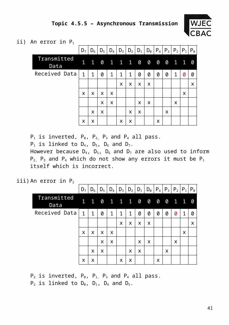
P3 is inverted, P0, P1 and P2 all pass.P3 is linked to D1, D2, D5 and D6
However because D1, D2, D5 and D6 are also used to inform P0, P1 and P2 which do not show any errors it must be P3 itself which is incorrect.
ii) the effect of an error in P2.
D7 D6 D5 D4 D3 D2 D1 D0 P3 P2 P1 P0
1 1 0 1 1 1 0 0 0 0 1 0
x x x x x
x x x x x
x x x x x
x x x x x
P2 is inverted, P0, P1 and P3 all pass.P2 is linked to D0, D1, D4 and D5
However because D0, D1, D4 and D5 are also used to inform P0, P1 and P3 which do not show any errors it must be P2 itself which is incorrect.
iii) the effect of an error in P1.
D7 D6 D5 D4 D3 D2 D1 D0 P3 P2 P1 P0
27
Module ET4 – Communication Systems
1 1 0 1 1 1 0 0 0 1 0 0
x x x x x
x x x x x
x x x x x
x x x x x
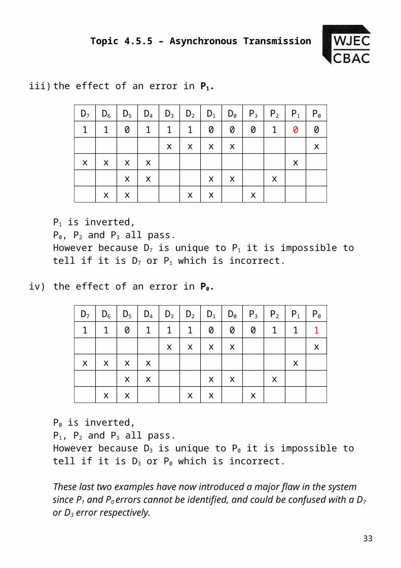
P1 is inverted,P0, P2 and P3 all pass.However because D7 is unique to P1 it is impossible to tell if it is D7 or P1 which is incorrect.
iv) the effect of an error in P0.
D7 D6 D5 D4 D3 D2 D1 D0 P3 P2 P1 P0
1 1 0 1 1 1 0 0 0 1 1 1
x x x x x
x x x x x
x x x x x
x x x x x
P0 is inverted,P1, P2 and P3 all pass.However because D3 is unique to P0 it is impossible to tell if it is D3 or P0 which is incorrect.
These last two examples have now introduced a major flaw in the system since P1 and P0 errors cannot be identified, and could be confused with a D7 or D3 error respectively.
Advantages of the 4 bit parity system.
A single error in any of the data locations can be detected and
corrected at the receiver.
Disadvantages of the 4 bit parity system.
28
Topic 4.5.5 – Asynchronous Transmission
Double errors in the data would not be corrected but depending on
which bits were affected they may be detected.
If an error occurs in the parity bits then they may or may not be
detected.
Four extra bits need to be transmitted for every byte of data to be
transmitted increasing the transmission time.
What started out as a very promising system for detecting and correcting errors in data transmission fell apart when an error occurred in the parity bits.
Careful consideration of the way in which the parity bits are assigned in the four bit system should reveal why the system has this weakness. The problem arises because P0 and P1 are linked to either data bit D3 or D7 respectively.
Data bits D3 and D7 do not affect any other parity bit, making it impossible to determine where an error has occurred – in the data bit or parity bit. All of the other data bits affect two or more parity bits, and therefore it is possible to determine where the error lies in the data section or in the parity section.
29
Module ET4 – Communication Systems
5-bit Parity Systems
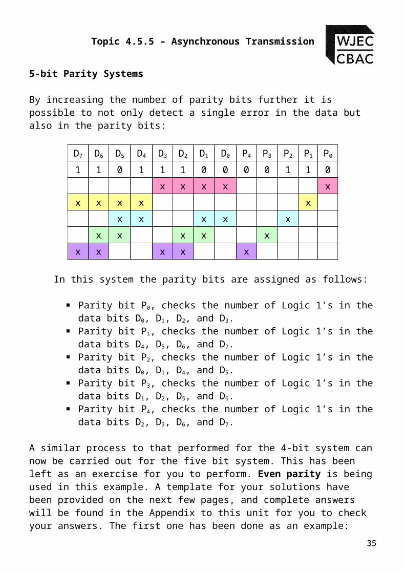
By increasing the number of parity bits further it is possible to not only detect a single error in the data but also in the parity bits:
D7 D6 D5 D4 D3 D2 D1 D0 P4 P3 P2 P1 P0
1 1 0 1 1 1 0 0 0 0 1 1 0
x x x x x
x x x x x
x x x x x
x x x x x
x x x x x
In this system the parity bits are assigned as follows:
Parity bit P0, checks the number of Logic 1’s in the data bits D0, D1, D2, and D3.
Parity bit P1, checks the number of Logic 1’s in the data bits D4, D5, D6, and D7.
Parity bit P2, checks the number of Logic 1’s in the data bits D0, D1, D4, and D5.
Parity bit P3, checks the number of Logic 1’s in the data bits D1, D2, D5, and D6.
Parity bit P4, checks the number of Logic 1’s in the data bits D2, D3, D6, and D7.
A similar process to that performed for the 4-bit system can now be carried out for the five bit system. This has been left as an exercise for you to perform. Even parity is being used in this example. A template for your solutions have been provided on the next few pages, and complete answers will be found in the Appendix to this unit for you to check your answers. The first one has been done as an example:
30

Topic 4.5.5 – Asynchronous Transmission
Student Exercise 2
i) An error in D0
D7 D6 D5 D4 D3 D2 D1 D0 P4 P3 P2 P1 P0
Transmitted Data
1 1 0 1 1 1 0 0 0 0 1 1 0
Received Data 1 1 0 1 1 1 0 1 0 0 1 1 0
x x x x x
x x x x x
x x x x x
x x x x x
x x x x x
Which parity bits have failed ? ………P0 and P2 ………………………………………
Which data bit is common to the failed parity bits ? ……D0…………………
ii) An error in D1
D7 D6 D5 D4 D3 D2 D1 D0 P4 P3 P2 P1 P0
Transmitted Data
1 1 0 1 1 1 0 0 0 0 1 1 0
Received Data 1 1 0 1 1 1 1 0 0 0 1 1 0
x x x x x
x x x x x
x x x x x
x x x x x
x x x x x
Which parity bits have failed ? ……………………………………………………………………
31

Module ET4 – Communication Systems
Which data bit is common to the failed parity bits ? ……………………………
iii) An error in D2
D7 D6 D5 D4 D3 D2 D1 D0 P4 P3 P2 P1 P0
Transmitted Data
1 1 0 1 1 1 0 0 0 0 1 1 0
Received Data 1 1 0 1 1 0 0 0 0 0 1 1 0
x x x x x
x x x x x
x x x x x
x x x x x
x x x x x
Which parity bits have failed ? ……………………………………………………………………
Which data bit is common to the failed parity bits ? ……………………………
iv) An error in D3
D7 D6 D5 D4 D3 D2 D1 D0 P4 P3 P2 P1 P0
Transmitted Data
1 1 0 1 1 1 0 0 0 0 1 1 0
Received Data 1 1 0 1 0 1 0 0 0 0 1 1 0
x x x x x
x x x x x
x x x x x
x x x x x
x x x x x
Which parity bits have failed ? ……………………………………………………………………
32
Topic 4.5.5 – Asynchronous Transmission
Which data bit is common to the failed parity bits ? ……………………………
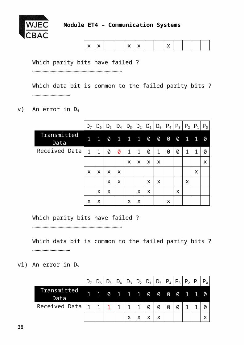
v) An error in D4
D7 D6 D5 D4 D3 D2 D1 D0 P4 P3 P2 P1 P0
Transmitted Data
1 1 0 1 1 1 0 0 0 0 1 1 0
Received Data 1 1 0 0 1 1 0 1 0 0 1 1 0
x x x x x
x x x x x
x x x x x
x x x x x
x x x x x
Which parity bits have failed ? ……………………………………………………………………
Which data bit is common to the failed parity bits ? ……………………………
vi) An error in D5
D7 D6 D5 D4 D3 D2 D1 D0 P4 P3 P2 P1 P0
Transmitted Data
1 1 0 1 1 1 0 0 0 0 1 1 0
Received Data 1 1 1 1 1 1 0 0 0 0 1 1 0
x x x x x
x x x x x
x x x x x
x x x x x
x x x x x
Which parity bits have failed ? ……………………………………………………………………
33

Module ET4 – Communication Systems
Which data bit is common to the failed parity bits ? ……………………………
vii) An error in D6
D7 D6 D5 D4 D3 D2 D1 D0 P4 P3 P2 P1 P0
Transmitted Data
1 1 0 1 1 1 0 0 0 0 1 1 0
Received Data 1 0 0 1 1 1 0 0 0 0 1 1 0
x x x x x
x x x x x
x x x x x
x x x x x
x x x x x
Which parity bits have failed ? ……………………………………………………………………
Which data bit is common to the failed parity bits ? ……………………………
viii) An error in D7
D7 D6 D5 D4 D3 D2 D1 D0 P4 P3 P2 P1 P0
Transmitted Data
1 1 0 1 1 1 0 0 0 0 1 1 0
Received Data 0 1 0 1 1 1 0 0 0 0 1 1 0
x x x x x
x x x x x
x x x x x
x x x x x
x x x x x
34
Topic 4.5.5 – Asynchronous Transmission
Which parity bits have failed ? ……………………………………………………………………
Which data bit is common to the failed parity bits ? ……………………………
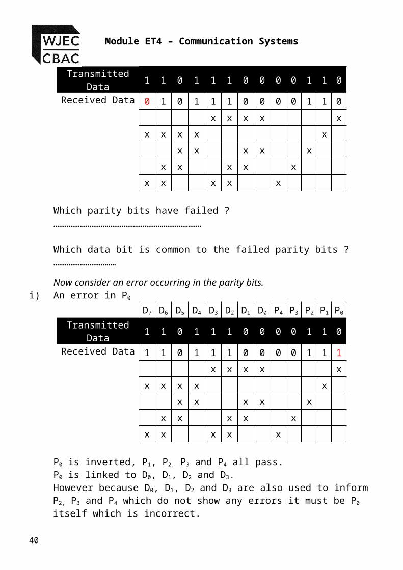
Now consider an error occurring in the parity bits.i) An error in P0
D7 D6 D5 D4 D3 D2 D1 D0 P4 P3 P2 P1 P0
Transmitted Data
1 1 0 1 1 1 0 0 0 0 1 1 0
Received Data 1 1 0 1 1 1 0 0 0 0 1 1 1
x x x x x
x x x x x
x x x x x
x x x x x
x x x x x
P0 is inverted, P1, P2, P3 and P4 all pass.P0 is linked to D0, D1, D2 and D3.However because D0, D1, D2 and D3 are also used to inform P2, P3 and P4 which do not show any errors it must be P0 itself which is incorrect.
ii) An error in P1
D7 D6 D5 D4 D3 D2 D1 D0 P4 P3 P2 P1 P0
Transmitted Data
1 1 0 1 1 1 0 0 0 0 1 1 0
Received Data 1 1 0 1 1 1 0 0 0 0 1 0 0
x x x x x
x x x x x
x x x x x
x x x x x
x x x x x
P1 is inverted, P0, P2, P3 and P4 all pass.35

Module ET4 – Communication Systems
P1 is linked to D4, D5, D6 and D7.However because D4, D5, D6 and D7 are also used to inform P2, P3 and P4 which do not show any errors it must be P1 itself which is incorrect.
iii) An error in P2
D7 D6 D5 D4 D3 D2 D1 D0 P4 P3 P2 P1 P0
Transmitted Data
1 1 0 1 1 1 0 0 0 0 1 1 0
Received Data 1 1 0 1 1 1 0 0 0 0 0 1 0
x x x x x
x x x x x
x x x x x
x x x x x
x x x x x
P2 is inverted, P0, P1, P3 and P4 all pass.P2 is linked to D0, D1, D4 and D5.However because D0, D1, D4 and D5 are also used to inform P0, P1 and P5 which do not show any errors it must be P2 itself which is incorrect.
iv) An error in P3
D7 D6 D5 D4 D3 D2 D1 D0 P4 P3 P2 P1 P0
Transmitted Data
1 1 0 1 1 1 0 0 0 0 1 1 0
Received Data 1 1 0 1 1 1 0 0 0 1 1 1 0
x x x x x
x x x x x
x x x x x
x x x x x
x x x x x
P3 is inverted, P0, P1, P2 and P4 all pass.P3 is linked to D1, D2, D5 and D6.
36

Topic 4.5.5 – Asynchronous Transmission
However because D1, D2, D5 and D6 are also used to inform P0, P2 and P4 which do not show any errors it must be P3 itself which is incorrect.
v) An error in P4
D7 D6 D5 D4 D3 D2 D1 D0 P4 P3 P2 P1 P0
Transmitted Data
1 1 0 1 1 1 0 0 0 0 1 1 0
Received Data 1 1 0 1 1 1 0 0 1 0 1 1 0
x x x x x
x x x x x
x x x x x
x x x x x
x x x x x
P4 is inverted, P0, P1, P2 and P3 all pass.P4 is linked to D2, D3, D6 and D7.However because D2, D3, D6 and D7 are also used to inform P0, P1 and P3 which do not show any errors it must be P4 itself which is incorrect.
Advantages of the 5 bit parity system
If any data bit is incorrect, then at least two parity bits will fail, this
identifies the error in the data bit itself.
If only a single parity bit fails then the error is in the parity bit
itself.
The possibility of a misunderstanding present in the 4-bit system
has been removed.
Disadvantages of the 5 bit parity system
Two errors still cause a problem to the system.
More data has to be transmitted, making the transmission time
longer.37
Module ET4 – Communication Systems
38

Topic 4.5.5 – Asynchronous Transmission
Where next ?
There is no end to the number of parity bits that can be added which will continue to improve the ability to detect and correct errors within the data, however every time we add parity bits we have to send extra information down the transmission line, and the more data we send the higher the risk that some of that data will become corrupted.
The other factor we have to take into account is the cost of adding all this additional encoding to data before it is transmitted and also at the receiving station, as well as the extra time spent sending the extra bits along the transmission line. Depending on the application the importance of the data and the ability to deal with an occasional error will determine how important error detection and correction is.
Examples :
1. If the data represents the characters of a newspaper article being sent from a reporter to head office, it is unlikely to cause a problem if the data becomes corrupted and has to be resent.
2. If the data forms the control codes for the cooling pumps in a Nuclear Reactor, a missing ‘1’ or ‘0’ may mean switch the pumps ‘off’ instead of ‘on’ and this may lead to a major disaster at the nuclear plant.
Clearly some form of compromise has to be reached depending on the criticality of the application, and how much companies decide that they want to spend on the process of detecting errors. For some applications where there is a lot of electrical ‘noise’ present, error checking and correction is essential and cost is secondary. Whilst in other situations there may be plenty of time to transmit a message and therefore a simple parity system is fine, and when an error occurs the whole of the data will be resent.
The following exercise will give you some practice questions on multiple parity bit systems.
Student Exercise 3
1. A computer network uses the RS232 protocol to transmit information down a serial link. Keyboard characters are
39
Module ET4 – Communication Systems
transmitted as an 11-bit binary number, made up of the 7-bit ASCII code, one parity bit, one start bit and two stop bits
The graph shows the waveform of a signal transmitted from a computer.
The signal carries the ASCII code for a single alphanumeric character.
(a) The signal includes a start bit and two stop bits, a parity bit, and 7 data bits corresponding to the ASCII character.
(i) Label the start bit, parity bit and the two stop bits. [2]
(ii) Write down the 7 bit character code. [1]
……………………………………………………………………………….
40
Topic 4.5.5 – Asynchronous Transmission
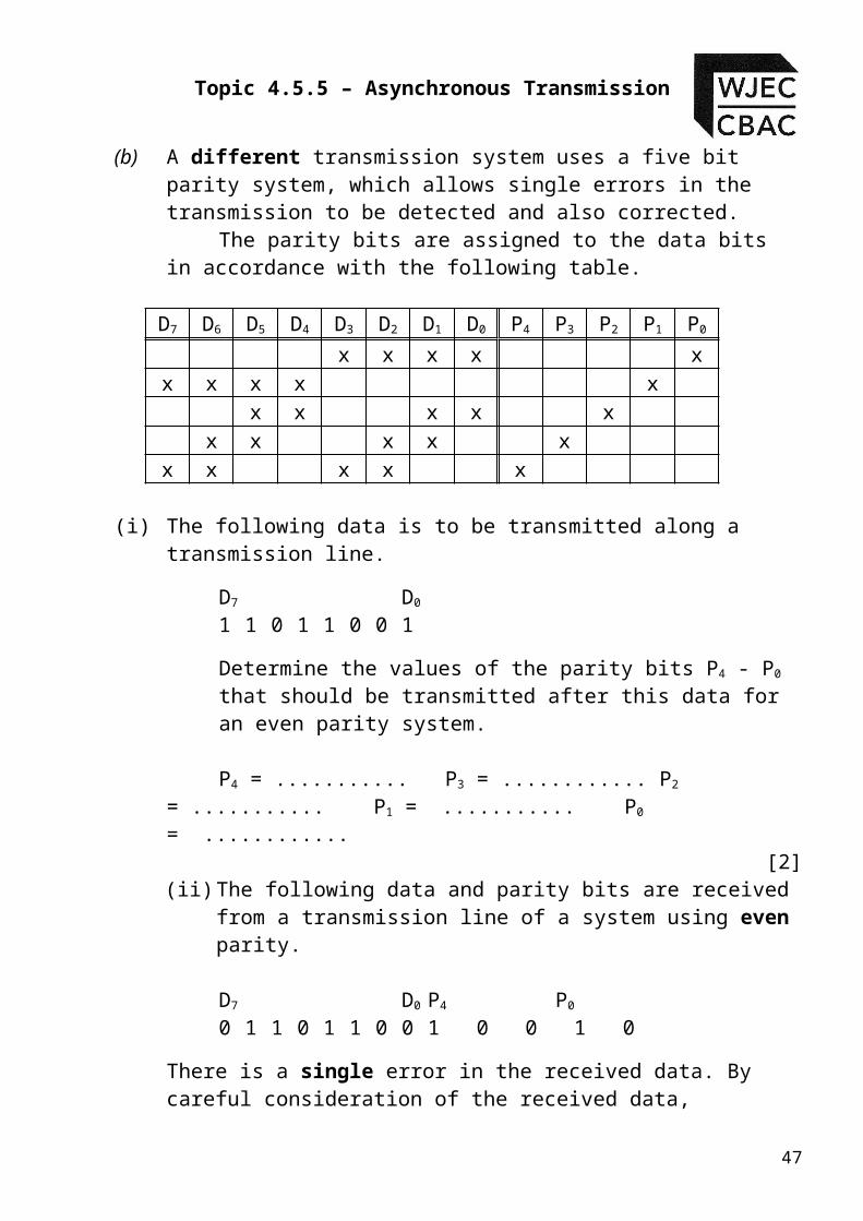
(b) A different transmission system uses a five bit parity system, which allows single errors in the transmission to be detected and also corrected. The parity bits are assigned to the data bits in accordance with the following table.
D7 D6 D5 D4 D3 D2 D1 D0 P4 P3 P2 P1 P0
x x x x xx x x x x
x x x x xx x x x x
x x x x x
(i) The following data is to be transmitted along a transmission line.
D7 D0
1 1 0 1 1 0 0 1
Determine the values of the parity bits P4 - P0 that should be transmitted after this data for an even parity system.
P4 = ........... P3 = ............ P2 = ........... P1 = ........... P0 = ............
[2](ii) The following data and parity bits are received from a
transmission line of a system using even parity.
D7 D0 P4 P0
0 1 1 0 1 1 0 0 1 0 0 1 0
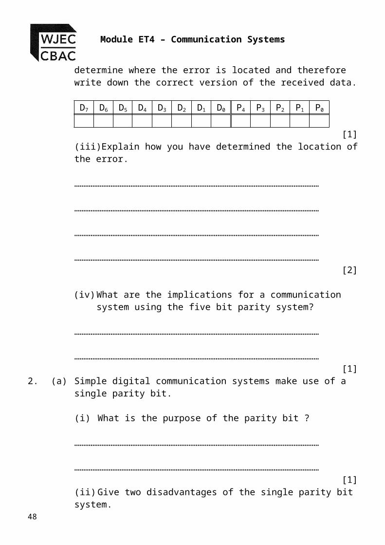
There is a single error in the received data. By careful consideration of the received data, determine where the error is located and therefore write down the correct version of the received data.
D7 D6 D5 D4 D3 D2 D1 D0 P4 P3 P2 P1 P0
[1](iii) Explain how you have determined the location of the error.
41

Module ET4 – Communication Systems
………………………………………………………………………………………………………………………
………………………………………………………………………………………………………………………
………………………………………………………………………………………………………………………
………………………………………………………………………………………………………………………
[2]
(iv) What are the implications for a communication system using the five bit parity system?
………………………………………………………………………………………………………………………
………………………………………………………………………………………………………………………
[1]2. (a) Simple digital communication systems make use of a single
parity bit.
(i) What is the purpose of the parity bit ?
………………………………………………………………………………………………………………………
42

Topic 4.5.5 – Asynchronous Transmission
………………………………………………………………………………………………………………………
[1] (ii) Give two disadvantages of the single parity bit system.
1.
……………………………………………………………………………………………………
2.
……………………………………………………………………………………………………
[2]
43

Module ET4 – Communication Systems
(b) Better error checking can be achieved using a 2 – bit parity system.
(i) Using the data 0 1 1 0 1 1 0 1, describe how a 2 – bit parity system would work. Assume that even parity is being used.
………………………………………………………………………………………………………………………
………………………………………………………………………………………………………………………
………………………………………………………………………………………………………………………
………………………………………………………………………………………………………………………
………………………………………………………………………………………………………………………
………………………………………………………………………………………………………………………
[3](ii) The following data is received from a transmission line, using
odd parity.
D7 D6 D5 D4 D3 D2 D1 D0 P1 P0
0 1 0 1 1 1 0 0 0 1
44

Topic 4.5.5 – Asynchronous Transmission
Determine if there is an error in the received data, and if so where is the error located ?
[1]
………………………………………………………………………………………………………………………
45

Module ET4 – Communication Systems
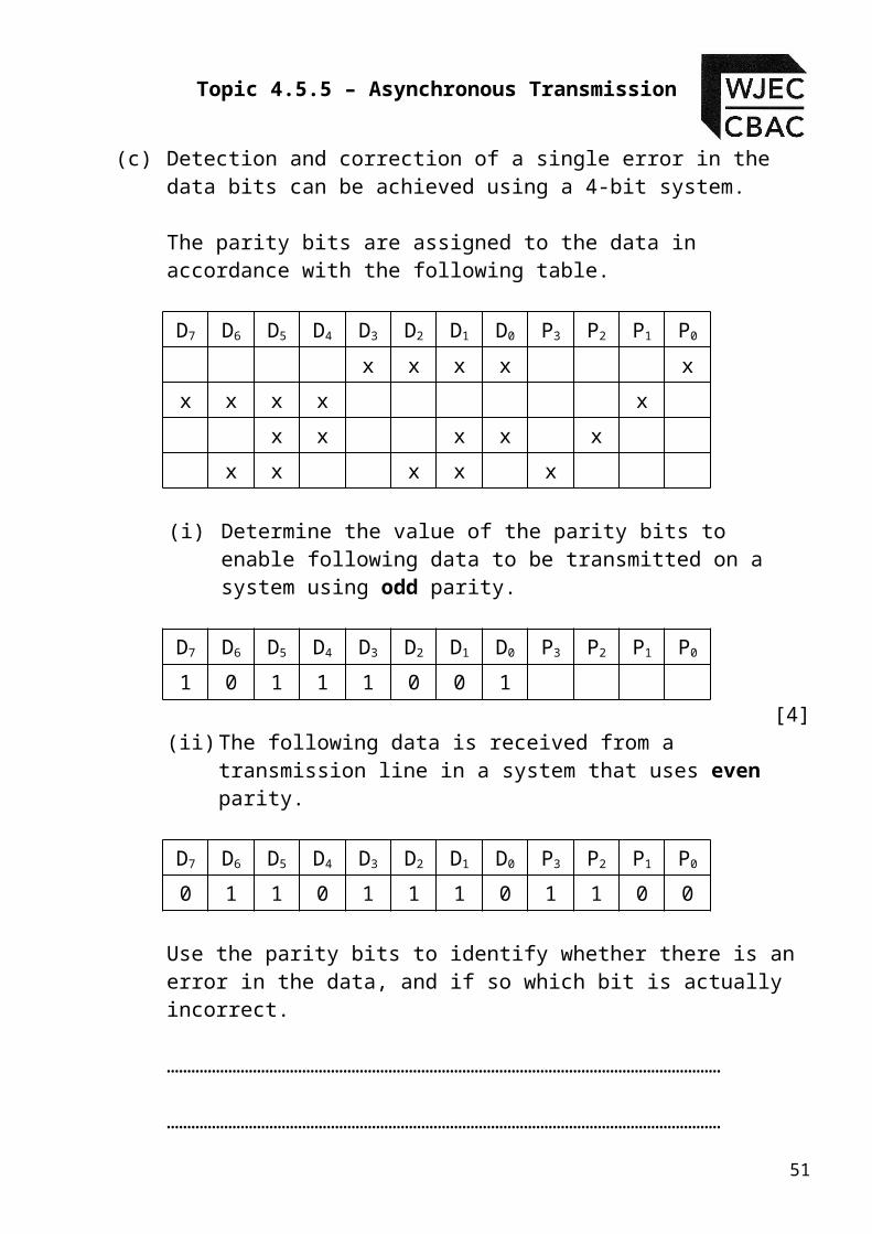
(c) Detection and correction of a single error in the data bits can be achieved using a 4-bit system.
The parity bits are assigned to the data in accordance with the following table.
D7 D6 D5 D4 D3 D2 D1 D0 P3 P2 P1 P0
x x x x x
x x x x x
x x x x x
x x x x x
(i) Determine the value of the parity bits to enable following data to be transmitted on a system using odd parity.
D7 D6 D5 D4 D3 D2 D1 D0 P3 P2 P1 P0
1 0 1 1 1 0 0 1
[4](ii) The following data is received from a transmission line in
a system that uses even parity.
D7 D6 D5 D4 D3 D2 D1 D0 P3 P2 P1 P0
0 1 1 0 1 1 1 0 1 1 0 0
Use the parity bits to identify whether there is an error in the data, and if so which bit is actually incorrect.
………………………………………………………………………………………………………………………
………………………………………………………………………………………………………………………
[2]
46
Topic 4.5.5 – Asynchronous Transmission
(iii) What is the major disadvantage of the four bit-parity system ?
[1]
………………………………………………………………………………………………………………………
………………………………………………………………………………………………………………………
………………………………………………………………………………………………………………………
47
Module ET4 – Communication Systems
Solutions to Student Exercises
Student Exercise 1:
1. i)
[2]ii) 0110110
[2]iii) The data contains 4 logic 1’s, the parity bit is set to 1 making
a total of 5 logic 1’s which is odd therefore the signal contains a single error.
[1]iv) The number of logic 1’s in the signal and parity bit is odd.
[1]2. a)
[2]b)
0010110[2]
c) There are 3 Logic 1’s in the data, and the parity bit is 0. This makes the total numbers of 1’s odd and therefore the parity check passes.
[1]
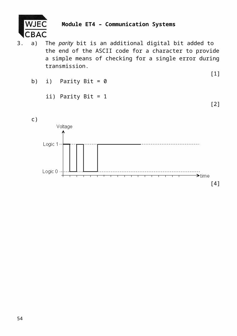
3. a) The parity bit is an additional digital bit added to the end of the ASCII code for a character to provide a simple means of checking for a single error during transmission.
[1]b) i) Parity Bit = 0
48
Sta
rt B
it
Par
ity
Bit
Par
ity
Bit
Sta
rt B
it

Topic 4.5.5 – Asynchronous Transmission
ii) Parity Bit = 1[2]
c)
[4]
49
Module ET4 – Communication Systems
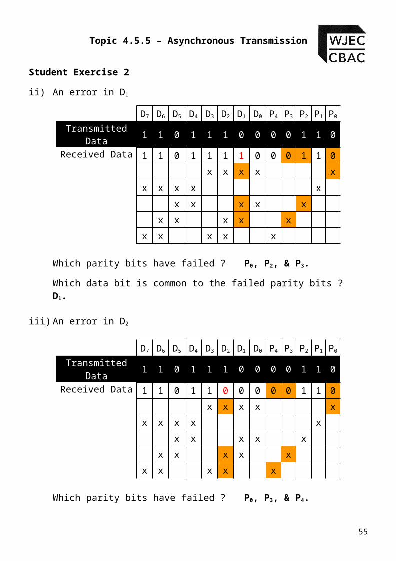
Student Exercise 2
ii) An error in D1
D7 D6 D5 D4 D3 D2 D1 D0 P4 P3 P2 P1 P0
Transmitted Data
1 1 0 1 1 1 0 0 0 0 1 1 0
Received Data 1 1 0 1 1 1 1 0 0 0 1 1 0
x x x x x
x x x x x
x x x x x
x x x x x
x x x x x
Which parity bits have failed ? P0, P2, & P3.
Which data bit is common to the failed parity bits ? D1.
iii) An error in D2
D7 D6 D5 D4 D3 D2 D1 D0 P4 P3 P2 P1 P0
Transmitted Data
1 1 0 1 1 1 0 0 0 0 1 1 0
Received Data 1 1 0 1 1 0 0 0 0 0 1 1 0
x x x x x
x x x x x
x x x x x
x x x x x
x x x x x
Which parity bits have failed ? P0, P3, & P4.
Which data bit is common to the failed parity bits ? D2.
iv) An error in D3
50
Topic 4.5.5 – Asynchronous Transmission
D7 D6 D5 D4 D3 D2 D1 D0 P4 P3 P2 P1 P0
Transmitted Data
1 1 0 1 1 1 0 0 0 0 1 1 0
Received Data 1 1 0 1 0 1 0 0 0 0 1 1 0
x x x x x
x x x x x
x x x x x
x x x x x
x x x x x
Which parity bits have failed ? P0 & P4.
Which data bit is common to the failed parity bits ? D3.
v) An error in D4
D7 D6 D5 D4 D3 D2 D1 D0 P4 P3 P2 P1 P0
Transmitted Data
1 1 0 1 1 1 0 0 0 0 1 1 0
Received Data 1 1 0 0 1 1 0 1 0 0 1 1 0
x x x x x
x x x x x
x x x x x
x x x x x
x x x x x
Which parity bits have failed ? P1 & P2.
Which data bit is common to the failed parity bits ? D4.
vi) An error in D5
D7 D6 D5 D4 D3 D2 D1 D0 P4 P3 P2 P1 P0
Transmitted 1 1 0 1 1 1 0 0 0 0 1 1 051
Module ET4 – Communication Systems
DataReceived Data 1 1 1 1 1 1 0 0 0 0 1 1 0
x x x x x
x x x x x
x x x x x
x x x x x
x x x x x
Which parity bits have failed ? P1, P2, & P3.
Which data bit is common to the failed parity bits ? D5.
vii) An error in D6
D7 D6 D5 D4 D3 D2 D1 D0 P4 P3 P2 P1 P0
Transmitted Data
1 1 0 1 1 1 0 0 0 0 1 1 0
Received Data 1 0 0 1 1 1 0 0 0 0 1 1 0
x x x x x
x x x x x
x x x x x
x x x x x
x x x x x
Which parity bits have failed ? P1, P3, & P4.
Which data bit is common to the failed parity bits ? D6.viii) An error in D7
D7 D6 D5 D4 D3 D2 D1 D0 P4 P3 P2 P1 P0
Transmitted Data
1 1 0 1 1 1 0 0 0 0 1 1 0
Received Data 0 1 0 1 1 1 0 0 0 0 1 1 0
x x x x x
52

Topic 4.5.5 – Asynchronous Transmission
x x x x x
x x x x x
x x x x x
x x x x x
Which parity bits have failed ? P1 & P4.
Which data bit is common to the failed parity bits ? D7.
53
Module ET4 – Communication Systems
Student Exercise 3
1. (a) (i)
[2]
(ii) 0111100
[1]
(b) (i) P4 = 1 P3 = 1 P2 = 0 P1 = 1 P0 = 0[2]
(ii)
D7 D6 D5 D4 D3 D2 D1 D0 P4 P3 P2 P1 P0
0 1 0 0 1 1 0 0 1 0 0 1 0[1]
(iii) Parity bits P1, P2 and P3 are incorrect. These bits correspond to data bit 5, which must be incorrect.
[2]
(iv) More data will have to be transmitted to ensure the accuracy of the data transmitted.
[1]
54
Sto
p B
it
Sto
p B
it
Sta
rt B
it
Par
ity
Bit
Topic 4.5.5 – Asynchronous Transmission
2. (a)(i) the parity bit is a simple form of error checking.
[1] (ii)
1. The single parity bit can only indicate that an error exists, it cannot locate the error.
2. The single parity may fail if two bits in the data become corrupted. The parity test may pass but the data could be corrupt.
[2](b)
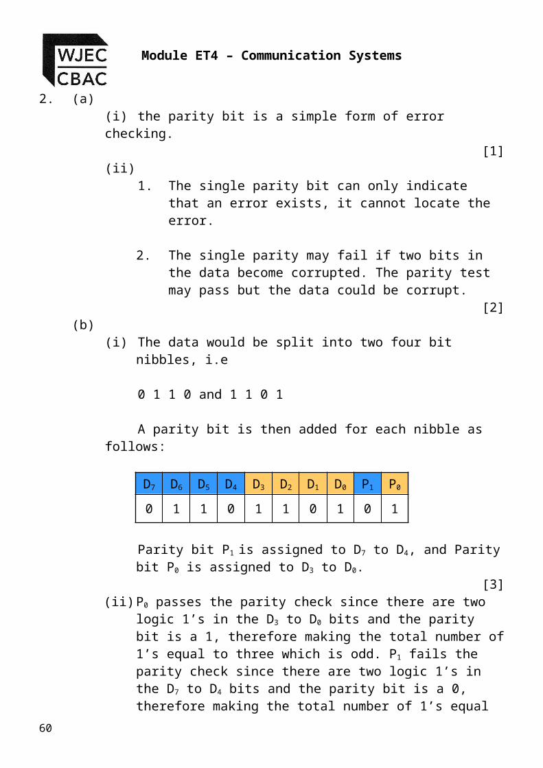
(i) The data would be split into two four bit nibbles, i.e
0 1 1 0 and 1 1 0 1
A parity bit is then added for each nibble as follows:
D7 D6 D5 D4 D3 D2 D1 D0 P1 P0
0 1 1 0 1 1 0 1 0 1
Parity bit P1 is assigned to D7 to D4, and Parity bit P0 is assigned to D3 to D0.
[3](ii) P0 passes the parity check since there are two logic 1’s
in the D3 to D0 bits and the parity bit is a 1, therefore making the total number of 1’s equal to three which is odd. P1 fails the parity check since there are two logic 1’s in the D7 to D4 bits and the parity bit is a 0, therefore making the total number of 1’s equal to two which is even and therefore parity fails. There is one error in the data bits D7 to D4.
[1]
55

Module ET4 – Communication Systems
(c) (i)
D7 D6 D5 D4 D3 D2 D1 D0 P3 P2 P1 P0
1 0 1 1 1 0 0 1 0 0 0 1
[4](ii)
D7 D6 D5 D4 D3 D2 D1 D0 P3 P2 P1 P0
0 1 1 0 1 1 1 0 1 1 0 0
Parity bits P0, P2, & P3 fail which corresponds to an error in D1
[2](iii) The four bit parity system cannot determine the location
of an error if the error occurs in the parity bits. [1]
Now it’s time to have a go at some examination questions.
56

Topic 4.5.5 – Asynchronous Transmission
Examination Style Questions
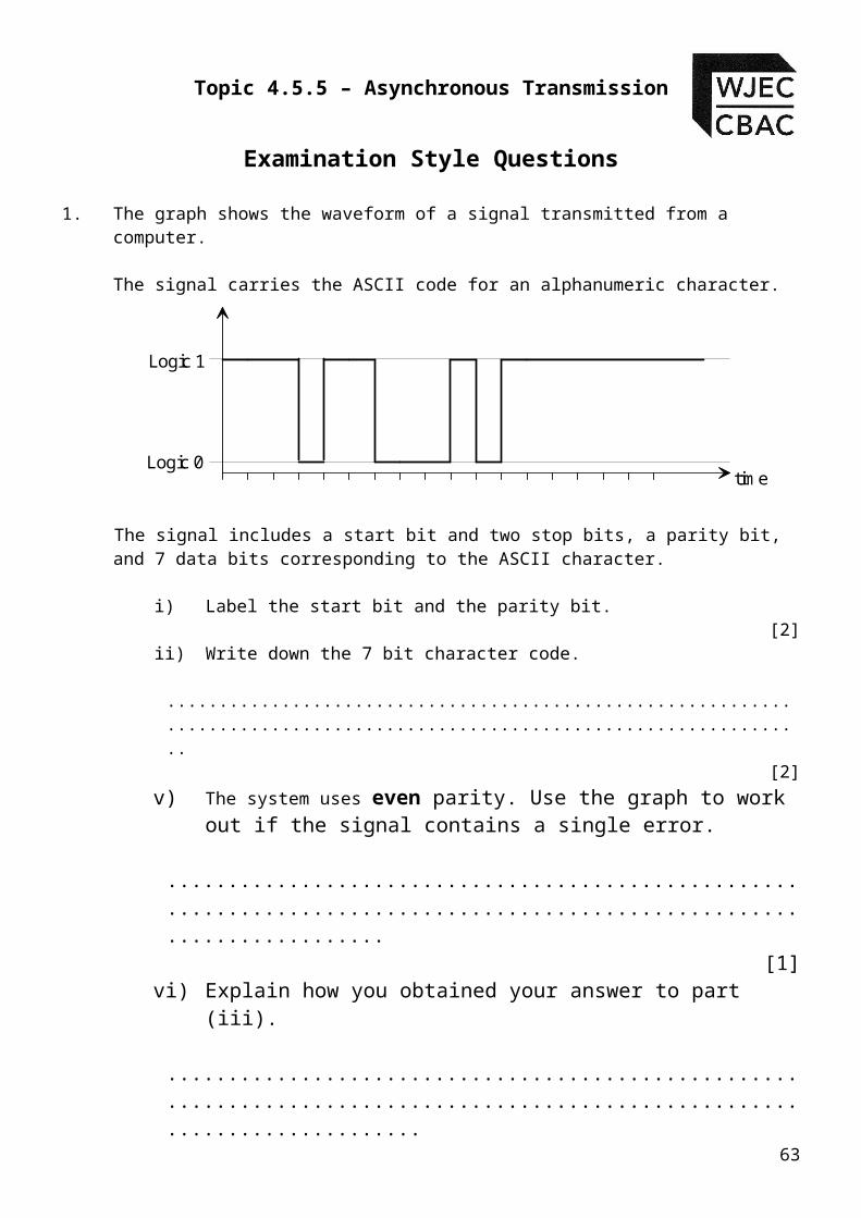
1. The graph shows the waveform of a signal transmitted from a computer.
The signal carries the ASCII code for an alphanumeric character.
Logic 1
Logic 0time
The signal includes a start bit and two stop bits, a parity bit, and 7 data bits corresponding to the ASCII character.
i) Label the start bit and the parity bit.[2]
ii) Write down the 7 bit character code.
..........................................................................................................................[2]
v) The system uses even parity. Use the graph to work out if the signal contains a single error.
..........................................................................................................................[1]
vi) Explain how you obtained your answer to part (iii).
.............................................................................................................................
.............................................................................................................................
.............................................................................................................................[1]
57

Module ET4 – Communication Systems
2. The graph shows the waveform of a signal received down an asynchronous serial communication link using odd parity.
The signal carries the ASCII code for an alphanumeric character.
Logic 1
Logic 0time
Voltage
The signal includes start and stop bits, a parity bit, and 7 data bits corresponding to the ASCII character.
a) Label the start bit and the parity bit.[2]
b) Write down the 7 bit character code.[2]
.............................................................................................................................
c) Determine if the signal contains an error by explaining how you reached your conclusion.
.............................................................................................................................
.............................................................................................................................
.............................................................................................................................
.............................................................................................................................[1]
58

Topic 4.5.5 – Asynchronous Transmission
3. The ASCII code is an internationally agreed method of coding alphanumeric characters in computer systems.
The following table gives the ASCII code for a number of different characters.
Character ASCII Code
A 1000001B 1000010E 1000101G 1000111
a) Before transmission of data takes place, a parity bit is added to the 7 bit ASCII code. Explain the purpose of the parity bit.
[1].......................................................................................................................................
.......................................................................................................................................
.......................................................................................................................................
b) Complete the following to show the logic state of the parity bit if:
i) Character “A” is transmitted using odd parity. Parity Bit = ............
ii) Character “G” is transmitted using even parity. Parity Bit = ............[2]
c) A transmission system uses odd parity. Start and stop bits are added before the signal is transmitted. Complete the following graph to show the waveform of the transmitted signal when the character “E” is transmitted.
Logic 1
Logic 0time
Voltage
[4]
59
Module ET4 – Communication Systems
4. A computer network uses the RS232 protocol to transmit information down a serial link. Keyboard characters are transmitted as an 11-bit binary number, made up of the 7-bit ASCII code, one parity bit, one start bit and two stop bits
The graph shows the waveform of a signal transmitted from a computer.
Logic 1
Logic 0time
The signal carries
the ASCII code for a single alphanumeric character.
(a) The signal includes a start bit and two stop bits, a parity bit, and 7 data bits corresponding to the ASCII character.
(i) Label the start bit, parity bit and the two stop bits. [2]
(ii) Write down the 7 bit character code. [1]
……………………………………………………………………………….
(b) A different transmission system uses a five bit parity system, which allows single errors in the transmission to be detected and also corrected.
The parity bits are assigned to the data bits in accordance with the following table.
D7 D6 D5 D4 D3 D2 D1 D0 P4 P3 P2 P1 P0
x x x x xx x x x x
x x x x xx x x x x
x x x x x
60

Topic 4.5.5 – Asynchronous Transmission
(i) The following data is to be transmitted along a transmission line.
D7 D0
0 1 0 1 0 0 1 1
Determine the values of the parity bits P4 - P0 that should be transmitted after this data for an even parity system.
P4 = ........... P3 = ............ P2 = ........... P1 = ........... P0 = ............[2]
(ii) The following data and parity bits are received from a transmission line of a system using even parity.
D7 D0 P4 P0
0 1 1 1 0 0 0 1 1 1 0 1 0
There is a single error in the received data. By careful consideration of the received data, determine where the error is located and therefore write down the correct version of the received data.
D7 D6 D5 D4 D3 D2 D1 D0 P4 P3 P2 P1 P0
[1](iii) Explain how you have determined the location of the error.
………………………………………………………………………………….
………………………………………………………………………………….
………………………………………………………………………………….
………………………………………………………………………………….[2]
(iv) What are the implications for a communication system using the five bit parity system?
………………………………………………………………………………….
………………………………………………………………………………….[1]
61

Module ET4 – Communication Systems
5. (a) Simple digital communication systems make use of a single parity bit.
(i) What is the purpose of the parity bit ?
…………………………………………………………………………………
…………………………………………………………………………………[1]
(ii) Give two disadvantages of the single parity bit system.
1. ……………………………………………………………………
2. ……………………………………………………………………[2]
(b) An improvement can be made by using a 2 – bit parity system.
(i) Using the data 0 1 1 0 1 1 0 1, describe how a 2 – bit parity system would work. Assume that even parity is being used.
…………………………………………………………………………………
…………………………………………………………………………………
…………………………………………………………………………………
…………………………………………………………………………………
…………………………………………………………………………………
…………………………………………………………………………………[3]
(ii) The following data is received from a transmission line, using odd parity.
D7 D6 D5 D4 D3 D2 D1 D0 P1 P0
0 1 0 1 1 1 0 0 0 1
Determine if there is an error in the received data, and if so where is the error located ?
[1]………………………………………………………………………………….
62
Topic 4.5.5 – Asynchronous Transmission
(c) More improvement can be obtained by using a four-bit parity system. This can permit the detection and correction of the data bits.
The parity bits are assigned to the data in accordance with the following table.
D7 D6 D5 D4 D3 D2 D1 D0 P3 P2 P1 P0
x x x x x
x x x x x
x x x x x
x x x x x
(ii) Determine the value of the parity bits to enable following data to be transmitted on a system using odd parity.
D7 D6 D5 D4 D3 D2 D1 D0 P3 P2 P1 P0
1 0 1 1 1 0 0 1
[4](ii) The following data is received from a transmission line in a system that
uses even parity.
D7 D6 D5 D4 D3 D2 D1 D0 P3 P2 P1 P0
0 1 1 0 1 1 1 0 1 1 0 0
Use the parity bits to identify whether there is an error in the data, and if so which bit is actually incorrect.
………………………………………………………………………………….
………………………………………………………………………………….[2]
(iii) What is the major disadvantage of the four bit-parity system ?[1]
…………………………………………………………………………………
…………………………………………………………………………………
………………………………………………………………………………...
63

Module ET4 – Communication Systems
6. A high grade digital communication system uses a five bit parity system.
(a) What is the advantage of using a 5 bit parity system ?
………………………………………………………………………………..
………………………………………………………………………………..
………………………………………………………………………………..
(b) The parity bits are assigned to the data bits in accordance with the following table.
D7 D6 D5 D4 D3 D2 D1 D0 P4 P3 P2 P1 P0
x x x x xx x x x x
x x x x xx x x x x
x x x x x
(i) The following data is to be transmitted along a transmission line.
D7 D0
1 1 1 0 1 0 0 1
Determine the values of the parity bits P4 - P0 that should be transmitted after this data for an odd parity system.
P4 = ........... P3 = ............ P2 = ........... P1 = ........... P0 = ............[2]
64

Topic 4.5.5 – Asynchronous Transmission
(ii) The following data and parity bits are received from a transmission line of a system using even parity.
D7 D0 P4 P0
0 0 1 1 1 0 1 0 1 0 0 1 0
There is a single error in the received data. By careful consideration of the received data, determine where the error is located and therefore write down the correct version of the received data.
D7 D6 D5 D4 D3 D2 D1 D0 P4 P3 P2 P1 P0
[1](iii) Explain how you have determined the location of the error.
………………………………………………………………………………….
………………………………………………………………………………….
………………………………………………………………………………….
………………………………………………………………………………….[2]
65

Module ET4 – Communication Systems
7. The graph shows the waveform of a signal transmitted from a computer.
The signal carries the ASCII code for an alphanumeric character.
Logic 1
Logic 0time
The signal includes a start bit and two stop bits, a parity bit, and 7 data bits corresponding to the ASCII character.
i) Label the start bit and the parity bit.[2]
ii) Write down the 7 bit character code.
..................................................................................................................[2]
iii) There is no error in the transmitted signal. Use the graph to work out if the system used odd or even parity.
The system uses ................... parity.[1]
66

Topic 4.5.5 – Asynchronous Transmission
8. The ASCII code is an internationally agreed method of coding alphanumeric characters in computer systems. The following table gives the ASCII code for a number of different characters.
Character ASCII Code
A 1000001B 1000010E 1000101G 1000111
a) Complete the following to show the logic state of the parity bit if:
i) Character “E” is transmitted using odd parity. Parity Bit = ............
ii) Character “A” is transmitted using even parity. Parity Bit = ............[2]
b) A computer system uses even parity. Start and stop bits have to be added before the signal can be transmitted. Complete the graph to show the signal for the character “G”. Label the start, stop and parity bits.
Logic 1
Logic 0time
Voltage
[4]
c) A different computer system uses odd parity. Start and stop bits have to be added before the signal can be transmitted. Complete the graph to show the signal for the character “B”. Label the start, stop and parity bits. [4]
67
Logic 1
Logic 0time
Voltage

Module ET4 – Communication Systems
9. a. A computer network uses the RS232 protocol to transmit information through a serial link. The ASCII code is an international code for transmitting keyboard characters. Each character is transmitted as a 10-bit binary numbers, made up of the 7-bit ASCII code, one parity bit, one start bit and one stop bit.
The table below shows the ASCII code for five letters and the corresponding parity bit.
Character ASCII Code Parity bit
A 1000001 1K 1001011 0P 1010000 1d 1100100 0o 1101111 1
i) Which letter has a parity bit that is incorrect for a system that uses odd parity?
.......................................[1]
ii) Complete the timing diagram to show the waveform of the 10-bit signal corresponding to the letter ‘d’. The communication link is in standby initially.
Logic 1
Logic 0time
Voltage
[4]iii) Label the start, stop and parity bits.
[2]
68

Topic 4.5.5 – Asynchronous Transmission
Self Evaluation Review
Learning ObjectivesMy personal review of these objectives:
describe asynchronous character framing in terms of the start and stop bits, data bits and parity bit;appreciate that the ability to detect and correct errors that occur during digital transmissions is not possible with analogue systems; describe how using extra parity bits can provide error detection and correction;describe and use two-bit parity-bit systems to speed up data transfer by only having to retransmit half of the data when an error is detecteddescribe and use a five parity-bit system to identify and correct a single error if it has occurred;realise that even with multiple parity-bit systems it is not always possible to detect and correct errors when more than one bit is affected;appreciate that there is a trade off between the ability to check and correct data and the extra transmission costs; realise that in very noisy or sensitive applications it is often essential to have a high level of data checking despite the extra cost involved.
Targets: 1.
………………………………………………………………………………………………………………
………………………………………………………………………………………………………………
2. ………………………………………………………………………………………………………………
69

Module ET4 – Communication Systems
………………………………………………………………………………………………………………
70


![Exploiting Asynchronous V2V Transmission for Sensing ... · waveform [e.g., frequency modulated continuous waveform (FMCW)] and analyzing its reflection by the object [19]. Particularly,](https://static.fdocuments.in/doc/165x107/5b926aab09d3f206218b494f/exploiting-asynchronous-v2v-transmission-for-sensing-waveform-eg-frequency.jpg)


![Asynchronous Transfer Mode (ATM) FundamentalsX.25, frame relay, transmission control protocol [TCP]/Internet protocol [IP], ATM integrates the multiplexing and switching functions,](https://static.fdocuments.in/doc/165x107/5f0cea497e708231d437c2ad/asynchronous-transfer-mode-atm-fundamentals-x25-frame-relay-transmission-control.jpg)