ASTM D445: Standard Test Method for Kinematic...
6
Designation: 0445 - 65 Reapproved (1970) American National Standard Zll.107-1965 America n Natio nal Sta ndards Institute Designation: 71/66 Standard Method of Test for Method 305.6-Federal Test Method Standard No. 791 b VISCOSITY OF TRANSPARENT AND OPAQUE LIQUIDS (KINEMATIC AND DYNAMIC VISCOSITI ES)l This Standard is issued under the fixed designation D 445; the number immediately following the designation indicates the year of original adoption or, in the case of revision, the year of last revision. A number in parentheses indicates the year of last reapproval. This is also a standard of the Institute of Petroleum issued under the fixed designation IP 71. The final number indicates the year of last revision. This method was adopted as ajoint ASTM-IP standard ill 1964. 1. Scope 1.1 This method covers the determination of the kinematic viscosity of liquid petroleum products (Notes 1 and 2), both transparent and opaque, by measuring the time of flow of a fixed volume of liquid at a given tempera- ture through calibrated glass capillary instru- ments, using "gravity-flow." A procedure is given for a calculation of dynamic viscosities from measured kinematic viscosities. NOTE I-Bitumens are excepted; for the similar measurement of their viscosity, see ASTM Method D 2170, Test for Kinematic Viscosity of Asphalts,2 and ASTM Method D 2171, Test for Absolute Vis- cosity of AsphaJts. 2 NOTE 2-The method is intended for use with liquids, in which the rate of shear is proportional to the shearing stress (Newtonian flow). The propor- tionality constant is the coefficient of viscosity. With certain products which exhibit "gel-like" be- havior, care must be taken that measurements are made at sufficiently high temperatures for such materials to flow freely so that similar results will be obtained in viscometers of different capillary diameters. 2. Definitions 2.1 kinematic viscosity-a measure of the time for a fixed volume of liquid to flow by gravity through a capillary. The cgs unit of kinematic viscosity is the stoke which has the dimensions centimeters-squared per second. In the petroleum industry kinematic viscosity is usually expressed in centistokes, cSt, so that 1 St = 100 cSt. 2.2 dynamic viscosity (sometimes called absolute viscosity) is numerically the product of kinematic viscosity and the density of the liquid, both at the same temperature. The cgs unit of dynamic viscosity is the poise, P, which has the dimensions grams per centime- ter per second. 3. Summary of Method 3.1 The time is measured for a fixed vol- ume of the liquid to flow through the capillary viscometer under an accurately reproducible head and at a closely controlled temperature. The kinematic viscosity is then calculated from the measured flow time and the calibra- tion constant of the viscometer. 4. Apparatus 4.1 Viscometers, calibrated glass capillary type, capable of measuring viscosity within the limits of repeatability and reproducibility given in Section 10 are acceptable. Those vis- cometers listed in Table 1 meet these require- ments. NOTE 3-The calibration constant, C, is depend- ent upon the gravitational acceleration at the place of calibration and this must, therefore, be supplied by the standardization laboratory together with the instrument constant. Where the acceleration of gravity, g, in the two locations differs by more than I This method is under the jurisdiction of ASTM Com- mittee D-2 on Petroleum Products and Lubricants. A list of members may be found in the ASTM Yearbook. Current edition effective Aug. 31, 1965. Originally is- sued 1937. Replaces D 445 - 65. In the IP, this method is under the jurisdiction of the Standardization Committee. In 1965, the appended material describing viscometers was deleted. Other editorial changes were made to take care of comments from the Institute of Petroleum. 2 Anllua! Book of ASTM Standards, Part 11. 184
Transcript of ASTM D445: Standard Test Method for Kinematic...

~~l~ Designation: 0445 - 65 Reapproved (1970) American National Standard Zll.107-1965 America n Natio nal Sta ndards Institute
Designation: 71/66
Standard Method of Test for
Method 305.6-Federal Test Method Standard No. 791 b
VISCOSITY OF TRANSPARENT AND OPAQUE LIQUIDS (KINEMATIC AND DYNAMIC VISCOSITI ES)l
This Standard is issued under the fixed designation D 445; the number immediately following the designation indicates the year of original adoption or, in the case of revision, the year of last revision. A number in parentheses indicates the year of last reapproval. This is also a standard of the Institute of Petroleum issued under the fixed designation IP 71. The final number indicates the year of last revision.
This method was adopted as ajoint ASTM-IP standard ill 1964.
1. Scope
1.1 This method covers the determination of the kinematic viscosity of liquid petroleum products (Notes 1 and 2), both transparent and opaque, by measuring the time of flow of a fixed volume of liquid at a given temperature through calibrated glass capillary instruments, using "gravity-flow." A procedure is given for a calculation of dynamic viscosities from measured kinematic viscosities.
NOTE I-Bitumens are excepted; for the similar measurement of their viscosity, see ASTM Method D 2170, Test for Kinematic Viscosity of Asphalts,2 and ASTM Method D 2171, Test for Absolute Viscosity of AsphaJts.2
NOTE 2-The method is intended for use with liquids, in which the rate of shear is proportional to the shearing stress (Newtonian flow). The proportionality constant is the coefficient of viscosity. With certain products which exhibit "gel-like" behavior, care must be taken that measurements are made at sufficiently high temperatures for such materials to flow freely so that similar results will be obtained in viscometers of different capillary diameters.
2. Definitions
2.1 kinematic viscosity-a measure of the time for a fixed volume of liquid to flow by gravity through a capillary. The cgs unit of kinematic viscosity is the stoke which has the dimensions centimeters-squared per second. In the petroleum industry kinematic viscosity is usually expressed in centistokes, cSt, so that 1 St = 100 cSt.
2.2 dynamic viscosity (sometimes called absolute viscosity) is numerically the product of kinematic viscosity and the density of the
liquid, both at the same temperature. The cgs unit of dynamic viscosity is the poise, P, which has the dimensions grams per centimeter per second.
3. Summary of Method
3.1 The time is measured for a fixed volume of the liquid to flow through the capillary viscometer under an accurately reproducible head and at a closely controlled temperature. The kinematic viscosity is then calculated from the measured flow time and the calibration constant of the viscometer.
4. Apparatus
4.1 Viscometers, calibrated glass capillary type, capable of measuring viscosity within the limits of repeatability and reproducibility given in Section 10 are acceptable. Those viscometers listed in Table 1 meet these requirements.
NOTE 3-The calibration constant, C, is dependent upon the gravitational acceleration at the place of calibration and this must, therefore, be supplied by the standardization laboratory together with the instrument constant. Where the acceleration of gravity, g, in the two locations differs by more than
I This method is under the jurisdiction of ASTM Committee D-2 on Petroleum Products and Lubricants. A list of members may be found in the ASTM Yearbook.
Current edition effective Aug. 31, 1965. Originally issued 1937. Replaces D 445 - 65.
In the IP, this method is under the jurisdiction of the Standardization Committee.
In 1965, the appended material describing viscometers was deleted. Other editorial changes were made to take care of comments from the Institute of Petroleum.
2 Anllua! Book of ASTM Standards, Part 11.
184

O. I percent, correct the calibration constant as follows:
C2 = (g2/g,) X Ct where the subscripts I and 2 indicate respectively the standardization laboratory and the testing laboratory.
NOTE 4-Specifications for these viscometers are described in ASTM Specification D 2515, for Kinematic Glass Viscometers.3
4.2 Viscometer Holders or Frames to enable the viscometer to be suspended securely in the bath in the same vertical position as when calibrated, using a plum bline or accurate level.
4.3 Viscometer Thermostat-Any transparent liquid or vapor bath of sufficient depth such that at no time during the measurement will any portion of the sample in the viscometer be less than 20 mm below the surface of the bath liquid or less than 20 mm above the bottom of the bath may be used. The temperature control must be such that for the range of 60 to 212 F (15 to 100 C) the temperature of the bath medium does not vary by more than 0.02 F (0.01 C) over the length of the viscometers, or between the position of each vis.:. co meter, or at the location of the thermometer. For temperatures outside this range, the variation must not exceed 0.05 F (0.03 C).
4.4 Temperature-Measuring Device-Suitable 1iquid-in-glass Kinematic Viscosity Test Thermometers, covering the range of test temperatures indicated in Table 2, as specified in ASTM Specification E 1, for ASTM Thermometers,4 and in the IP requirements for IP Standard Thermometers; make certain that they have been standardized before use (see Section 5). Any other thermometric device is permissible provided that the same accuracy can be obtained.
4.5 Timing Device-Any device may be used provided it is graduated in divisions representing not more than 0.2 s and has an accuracy of at least ±0.05 percent when tested over intervals of 15 min. A stop watch or other spring-actuated timer is permissible. Also, electrical timing devices may be used when the current frequency is controlled to an
. accuracy of 0.0 1 percent or better.
NOTE 5-AIternating currents as provided by some public power systems are intermittently, not continuously, controlled; when used to actuate electrical timing devices, such intermittent control can cause large errors in viscosity flow time measurement.
185
D 445
5. Standa .. dization
5.1 Viscometers-Only calibrated viscometers shall be used.
5.2 Thermometers-Routine liquid-in-glass thermometers should be checked to the nearest 0.02 F (0.01 C) by direct comparison with a suitable standardized thermometer. Kinematic Viscosity Test Thermometers shall be standardized at "total immersion" which means immersion to the top of the mercury column, with the remainder of the stem and the expansion chamber at the top of the thermometer exposed to room temperature; do not submerge the expansion bulb at the top of the thermometer. It is essential that the ice point of standardized thermometers be determined before use and the official corrections be adjusted to conform to the change in ice point.
5.3 Timers-In the United States of America, time signals as broadcast by the National Bureau of Standards, Station WWV, Washington, D. C., at 2.5, 5, 10, 15,20, 25, 30, and 35 MHz are a convenient and primary standard reference for calibrating timing devices; the signals are broadcast 24 h daily. Station CHU from Ottawa, Canada, at 3.330, 7.335 and 14.670 MHz or Station MSF at Rugby, United Kingdom, at 2.5, 5 and 10 MHz may be received better in some locations.
6. Procedure for Kinematic Viscosity
6.1 The specific' details of operation vary for the different types of viscometers listed in Table 1, In all cases, however, proceed in accordance with 6.1.1 through 6.1.9.
6.1.1 Ascertain that the thermometer has been standa~dized recently; new thermometers may require checking every week.
6.1.2 Maintain the bath at the test temperature within the limits given in 4.3. Apply the necessary corrections, if any, to all thermometer readings.
6.1.3 Select a clean, dry, calibrated viscometer which will give a flow time not less than the minimum specified for the viscometer, or 200 s, whichever is the greater .
6.1.4 Charge the viscometer (Note 6) in the manner dictated by the design of the instrument, this operation being in conformity with
3 Annual Book of ASTM Standards, Part 17. 4 Annual Book of ASTM Standards, Parts 18 and 30.
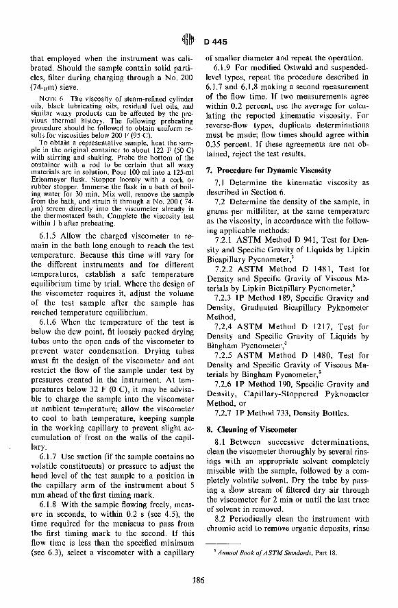
that employed when the instrument was calibrated. Should the sample contain solid particles, filter during charging through a No. 200 (74-j.tm) sieve.
NOTE 6-The viscosity of steam-refined cylinder oils, black lubricating oils, residual fuel oils, and similar waxy products can be affec~ed by the ~revious thermal history. The followmg preheatIng procedure should be followed to obtain uniform results for viscosities below 200 F (95 C).
To obtain a representative sample, heat the sample in the original con~ainer to about 122 F (50 C) with stirring and shakIng. Probe t~e bottom of the container with a rod to be certam that all waxy materials are in solution. Pour 100 ml into a 125-ml Erlenmeyer flask. Stopper loosely with a cork or rubber stopper. Immerse the flask in a bath of boiling water for 30 min. Mix well, remove the sample from the bath, and strain it through a No. 200 ( 7~Ilm) screen directly into the viscomete~ alr~ady In the thermostated bath. Complete the VISCOSIty test within I h after preheating.
6.1.5 Allow the charged viscometer to remain in the bath long enough to reach the test temperature. Because this time will vary for the different instruments and for different temperatures, establish a safe temperature equilibrium time by trial. Where the design of the viscometer requires it, adjust the volume of the test sample after the sample has reached temperature equilibrium.
6.1.6 When the temperature of the test is below the dew point, fit loosely packed drying tubes onto the open ends of the viscometer to prevent water condensation. Drying tubes must fit the design of the viscometer and not restrict the flow of the sample under test by pressures created in the instrument. At temperatures below 32 F (0 C), it may be advisable to charge the sample into the viscometer at ambient temperature; allow the viscometer to cool to bath temperature, keeping sample in the working capillary to prevent slight accumulation of frost on the walls of the capillary.
6.1.7 Use suction (if the sample contains no volatile constituents) or pressure to adjust the head level of the test sample to a position in the capillary arm of the instrument about 5 mm ahead of the first timing mark.
6.1.8 With the sample flowing freely, measure in seconds, to within 0.2 s (see 4.5), the time required for the meniscus to pass from the first timing mark to the second. If this flow time is less than the specified minimum (see 6.3), select a viscometer with a capillary
186
0445
of smaller diameter and repeat the operation. 6.1.9 For modified Ostwald and suspended
level types, repeat the procedure described in 6.1.7 and 6.1.8 making a second measurement of the flow time. If two measurements agree within 0.2 percent, use the average for calculating the reported kinematic viscosity. For reverse-flow types, duplicate determinations must be made; flow times should agree within 0.35 percent. If these agreements are not obtained, reject the test results.
7. Procedure for Dynamic Viscosity
7.1 Determine the kinematic viscosity as described in Section 6.
7.2 Determine the density of the sample, in grams per milliliter, at the same temperature as the viscosity, in accordance with the following applicable methods:
7.2.1 ASTM Method D 941, Test for Density and Specific Gravity of Liquids by Lipkin Bicapillary Pycnometer, 3
7.2.2 ASTM Method D 1481, Test for Density and Specific Gravity of Viscous Materials by Lipkin Bicapillary Pycnometer,5
7.2.3 IP Method 189, Specific Gravity and Density, Graduated Bicapillary Pyknometer Method,
7.2.4 ASTM Method D 1217, Test for Density and Specific Gravity of Liquids by Bingham Pycnometer, 3
7.2.5 ASTM Method D 1480, Test for Density and Specific Gravity of Viscous Materials by Bingham Pycnometer,5
7.2.6 IP Method 190, Specific Gravity and Density, Capillary-Stoppered Pyknometer Method, or
7.2.7 IP Method 733, Density Bottles.
8. Cleaning of Viscometer
8.1 Between successive determinations, clean the viscometer thoroughly by several rinsings with an appropriate solvent completely miscible with the sample, followed by a completely volatile solvent. Dry the tube by passing a s~ow stream of filtered dry air through the viscometer for 2 min or until the last trace of solvent in removed.
8.2 Periodically clean the instrument with chromic acid to remove organic deposits, rinse
5 Annual Book of ASTM Standards, Part 18.

thoroughly with distilled water and acetone, and dry with clean dry air. Inorganic deposits may be removed by hydrochloric acid treat~ mentbefore use of cleaning acid, particularly if barium salts are suspected.
8.3 Viscometers used for silicone fluids, fluorocarbons, and other liquids which are difficult to remove by the use of a cleaning agent, should be reserved for the exclusive use of those fluids except when standardizing. Such viscometers should be subjected to standardization checks at frequent intervals.
9. Calculations and Report
9.1 Calculate the kinematic viscosity ,as follows:
Kinematic viscosity, cSt = Ct
where: c= calibration constant of the viscometer,
cSt/s, and t = flow time, s.
9.2 Calculate the ?ynamic viscosity as follows:
Dynamic viscosity, cP = p v
where:
0445
p = density, g/cm3 (Note 6) at~ame temperature as kinemati.c viscosity, and
v = kinematic viscosity, cSt. NOTE 6-It is permissible to use density in g/ml
instead of g/cm3• The 12th General Conferenc~ on
Weights and Measures in November 1964 redefined the liter so that 1 ml is exactly I cm3
• The latter unit is preferred for expressing precise volume measurements.
9.3 Report both the viscosity and the temperature of test.
. 10. Precision
10.1 The following preCISlOn applies to Clean, transparent oils tested between 60 and 212 F (15 to 100 C):
10.1.1 Repeatability-Duplicate results by the same operator, using the same or different viscometers, should not be considered suspect unless their difference is greater than 0.35 percent of their mean. ,
10.1.2 Reproducibility-The results submitted by each of two laboratories should not be considered suspect unless their difference is . greater than 0.7 percent of their mean.
TABLE 1 Viscometer Types
Test Viscometers
A. Suspended Level Types for Transparent Liquids: I. BS/IP Suspended Level , 2. BS/IP Suspended Level, Shortened Form 3. BS/IP Minature Su~pended Level 4. Vbbelohde 5. FitzSimons 6. Atlantic 7. Cannon-Ubbelohde 8. Cannon-Ubbelohde Semi-Micro
B, Modified Ostwald Types for Transparent· Liquids: 1. Cannon-Fenske Routine 2. Zeitfuchs 3. BS/IP V-Tube 4. BS/JP V-Tube Miniature 5. SIL 6. Cannon-Manning Semi-Micro 7. Pinkevitch
C. Reverse-Flow Types for Transparent and Opaque Liquids: t. Cannon-Fenske Opaque 2. Zeitfuchs Cross-Arm 3. BS/IP V-Tube Reverse Flow 4. Lantz-Zeitfuchs
a Each range quoted requires a series of v isco meters.
187
Range, cSt"
2 to too 000 0.6 to 10 000 0.6 to 600 0.4 to 100 000 0.8 to 1 200 0.4 to 100 000 0.5 to 100 000 0.4 to 100 000
0.2 to 0.8 to 0.9 to 0.2 to 0.8 to 0.4 to 0.6 to
20000 3000
10000 100
10000 20000 15000
0.4 to 20 000 0.6 to 100 000 0.7 to 300 000 60 to 100000

~m~ D 445
TABLE 2 Kinematic Viscosity Thermometers
Temperature Range For Tests at Subdivisions Thermometer Number
degF degC degF degC degF degC ASTM IP
- 67 .5 to - 62. 5 -55.3 to -52.5 -65 -53.9 0.1 0.05 74 F 69 For C -61 to -29 -51.6 to -34 -60 to -30 -51 to -35 0.2 0.1 43 F 65 For C -42.5 to -37.5 -41.4 to -38.6 -40 -40 0.1 0.05 73 F 68 For C -2.5 to +2.5 -19.2 to -16.4 0 -17.8 0.1 0.05 72F 67 F or C 29 to 35 -2 to +2 32 0 0.1 0.05 33 F or C 66.5 to 71. 5 18.6 to 21.4 68 and 70 20 and 21. I 0.1 0.05 44F 29 For C 74.5 to 79.5 23.6 to 26.4 77 25 0.1 0.05 45 F 30 For C 97. 5 to 102. 5 36.6 to 39.4 100 37.8 0.1 0.05 28 F 31 F or C 119.5 to 124.5 48.6 to 51.4 122 50 0.1 0.05 46 F 66 For C 127.5 to 132.5 52.5 to 56.5 130 54.4 0.1 0.05 29 F 34 F or C 137.5 to 142.5 58 to 62 140 60 0.1 0.05 47 F 35 F or C 177.5 to 182.5 180 0.1 48 F 197 to 203 91 to 95 200 93.3 0.1 0.05 36 For C 207.5 to 212.5 98.6 to 101.4 210 and 212 98.9 and 100 0.1 0.05 30 F 32 F or C 272.5 to 277.5 275 0.1 110 F
APPENDIX
AI. CALIBRATION OF VISCOMETERS
At.t Reference Materials
A 1.1.1 Viscosity Oil Standards,6 conforming to ASTM viscosity oil standards having the approximate kinematic viscosity shown in Table AI. Certified kinematic viscosity values are established by cooperative tests and are supplied with each sample.
A1.2 Calibration
A 1.2.1 Using Liquid Standards-Select from Table A 1 a liquid standard having a minimum flow time of 200 s at the calibration temperature (preferably 100 F) and a viscosity in excess of the minimum shown in Table 1. Determine the flow time to the nearest 0.2 s in accordance with Section 6, and calculate the viscometer constant, C, as follows:
C = viI where: v = viscosity, cSt, for the standard liquid, and t = flow time, s.
A1.2.2 Using Standard Viscometers: A1.2.2.1 Select any petroleum oil that will have
a flow time of at least 200 s in both the standard and to-be-standardized visco meters; some viscometers, as listed in Table 1, require that the oil have a viscosity in excess of the minimum shown in order that the kinetic correction 7 will be less than 0.2 percent.
AI.2.2.2 Select a standard viscometer of known constant C. This viscometer may be a master viscometer that has been calibrated by the "step-up" procedure using visco meters of successively larger diameters starting with distilled water as the basic
188
viscosity standard8 or a routine viscometer of the same type that has been calibrated by comparison with a master viscometer. Mount the standard viscometer together with the viscometer to be calibrated in the same bath and determine the flow times of the oil in accordance with Section 6.
A 1.2.2.3 Calculate the constant C as follows:
C1 = (/2 X C2)lll
where: C1 C constant of the viscometer being calibrat
ed, II flow time to the nearest 0.2 s in the viscome
ter being calibrated, C2 = C constant of the standard viscometer, and 12 = flow time to the nearest 0.2 s in the standard
viscometer.
6 The viscosity standards are available in I-pt containers. See Table AI. Purchase orders should be addressed to the Cannon Instrument Co., P.O. Box 16, State College, Pa. 16801. Shipment will be made as specified or by best means.
7 Cannon, M. R., "Derivation of Viscosity Equation and Sources of Error in Viscometry;" Private Report No. I to ASTM Subcommittee on Viscosity, February 1950. Cannon, M. R., and Manning, R. E., "VIscosity Measurement, The Kinetic Energy Correction," Private Report No.2 to ASTM Subcommittee on Viscosity, April 1959. Copies available free of charge from The Cannon Instrument Co., P.O. Box 16, State College, Pa. 16801.
8 For a procedure for calibrating master viscometers, see ASTM Method D 2162, Test for Basic Calibration of Master Viscometers and Viscosity Oil I Standards, Annual Book of ASTM Standards, Part 17.

~~l~ D 445
TABLE At Viscosity Standards
Viscosity Approximate Kinematic Viscosity, cSt
Standard Con- At -53.89 At -40 At 98.89 forming to ASTM At20C At 25 C At 30 C At 37.78 C At50C Standards C C (68 F) (77 F) (86 F) (100 F) (122 F) C
(-65 F) (-40 F) (210 F)
S-3 300 80 4.6 4.0 3.0 1.2 S-6 10 9.0 6.0 1.8 S-20 44 35 20 3.9 S-60 160 120 60 7.7 S-200 700 480 200 16 S-600 2500 1600 600 280 32 S-2000 9000 5700 2000 76 S-8000 38 000 22000 8000 S-30 000 50000 27 000 11000
189