ASTER Shell: a simple concept to significantly increase ...
27
ASTER Shell: a simple concept to significantly increase the plastic buckling strength of short cylinders subjected to combined external pressure and axial compression Alain Combescure 1* and Jean‑Francois Jullien 2 Background e buckling of thin cylinders under axial compression or external pressure has been studied for many years [1–20] and is now well-understood. Geometric imperfections play a major role in a shell’s resistance to axial compression and, generally, a lesser role in its resistance to external pressure [21–37]. Fewer works can be found in the literature regarding the effect of plasticity on buckling [38–45]: plasticity plays an important role Abstract This paper proposes a new type of shell, similar to a cylindrical shell, which has sig‑ nificantly higher buckling strength when subjected to an arbitrary combination of uniform external pressure and axial compression. The underlying principle consists in a slight modification of the perfect cylinder in order to counteract the natural deforma‑ tions which get larger and larger and lead to the collapse of the structure. Such shells are called ASTER shells. The concept has been validated through experiments, then analyzed numerically in order to explain what was observed and to propose avenues for improvements. The shells were made of electrodeposited nickel. The material was characterized. The chosen specimens were carefully measured to characterize their thickness and initial imperfections, then tested under the various types of loading. Then they were analyzed using finite elements. Thus, we were able to compare the finite element predictions with the experimental results. This comparison shows that plasticity has a decisive influence on the critical load and that linear elastic dimension‑ ing leads to a serious overestimation of the experimental critical load. Contrary to perfect cylindrical shells, this type of shell is not significantly affected by geometric imperfections: this is another advantage of this type of design. Finally, we propose a numerical analysis in order to optimize the choice of the shape and propose shapes which resist buckling much better than a smooth cylinder when subjected to uniform external pressure, axial compression or a combination of both. Keywords: Plasticity, External pressure, Axial compression , Imperfections, Self‑ stiffening, Buckling, Finite elements, Tests, Plasticity, External pressure, Axial compression Open Access © 2015 Combescure and Jullien. This article is distributed under the terms of the Creative Commons Attribution 4.0 International License (http://creativecommons.org/licenses/by/4.0/), which permits unrestricted use, distribution, and reproduction in any medium, provided you give appropriate credit to the original author(s) and the source, provide a link to the Creative Commons license, and indicate if changes were made. RESEARCH ARTICLE Combescure and Jullien Adv. Model. and Simul. in Eng. Sci. (2015) 2:26 DOI 10.1186/s40323-015-0047-3 *Correspondence: alain.combescure@insa‑lyon. fr 1 SAFRAN‑AREVA‑Chair, LaMCoS UMR CNRS 5259, INSA‑LYON, Universite de Lyon, 61 AV President Wilson, 69621 Villeurbanne, France Full list of author information is available at the end of the article
Transcript of ASTER Shell: a simple concept to significantly increase ...

ASTER Shell: a simple concept to significantly increase the plastic buckling strength of short cylinders subjected to combined external pressure and axial compressionAlain Combescure1* and Jean‑Francois Jullien2
BackgroundThe buckling of thin cylinders under axial compression or external pressure has been studied for many years [1–20] and is now well-understood. Geometric imperfections play a major role in a shell’s resistance to axial compression and, generally, a lesser role in its resistance to external pressure [21–37]. Fewer works can be found in the literature regarding the effect of plasticity on buckling [38–45]: plasticity plays an important role
Abstract
This paper proposes a new type of shell, similar to a cylindrical shell, which has sig‑nificantly higher buckling strength when subjected to an arbitrary combination of uniform external pressure and axial compression. The underlying principle consists in a slight modification of the perfect cylinder in order to counteract the natural deforma‑tions which get larger and larger and lead to the collapse of the structure. Such shells are called ASTER shells. The concept has been validated through experiments, then analyzed numerically in order to explain what was observed and to propose avenues for improvements. The shells were made of electrodeposited nickel. The material was characterized. The chosen specimens were carefully measured to characterize their thickness and initial imperfections, then tested under the various types of loading. Then they were analyzed using finite elements. Thus, we were able to compare the finite element predictions with the experimental results. This comparison shows that plasticity has a decisive influence on the critical load and that linear elastic dimension‑ing leads to a serious overestimation of the experimental critical load. Contrary to perfect cylindrical shells, this type of shell is not significantly affected by geometric imperfections: this is another advantage of this type of design. Finally, we propose a numerical analysis in order to optimize the choice of the shape and propose shapes which resist buckling much better than a smooth cylinder when subjected to uniform external pressure, axial compression or a combination of both.
Keywords: Plasticity, External pressure, Axial compression , Imperfections, Self‑stiffening, Buckling, Finite elements, Tests, Plasticity, External pressure, Axial compression
Open Access
© 2015 Combescure and Jullien. This article is distributed under the terms of the Creative Commons Attribution 4.0 International License (http://creativecommons.org/licenses/by/4.0/), which permits unrestricted use, distribution, and reproduction in any medium, provided you give appropriate credit to the original author(s) and the source, provide a link to the Creative Commons license, and indicate if changes were made.
RESEARCH ARTICLE
Combescure and Jullien Adv. Model. and Simul.in Eng. Sci. (2015) 2:26 DOI 10.1186/s40323-015-0047-3
*Correspondence: alain.combescure@insa‑lyon.fr 1 SAFRAN‑AREVA‑Chair, LaMCoS UMR CNRS 5259, INSA‑LYON, Universite de Lyon, 61 AV President Wilson, 69621 Villeurbanne, FranceFull list of author information is available at the end of the article

Page 2 of 27Combescure and Jullien Adv. Model. and Simul. in Eng. Sci. (2015) 2:26
in the case of thicker cylinders and, coupled with initial imperfections, is often respon-sible for the significant decrease in the critical loads observed experimentally. This type of structure is also sensitive to the care with which the boundary conditions are applied [19, 46]. The effect of the model used for the boundary condition on the criti-cal load is also well-known, but it is more difficult to determine, in each practical case, the exact boundary condition which should be chosen. The literature on the buckling strength under combined axial compression and external pressure is less extensive [47]. The objective of this work is to propose a metallic shell which can be manufactured eas-ily and which, on the one hand, avoids the high sensitivity to imperfections of ordinary shells under axial compression while, on the other hand, having a much better resistance to external pressure. This leads to an alternative to the shell defined in [48, 49] by opti-mizing a NURBS surface. NURBS shells have better resistance to axial compression, but their resistance to external pressure has not been assessed. There is no theoretical study or experiment available for such shells when the material has the characteristic elastic-plastic behavior of metals.
The paper is organized as follows: the first section describes the ASTER shell concept, the experiments and the results. The second section describes the numerical prediction of these experiments and compares the results with the experimental results. The third section explains how these shells can be optimized to achieve a high resistance to exter-nal pressure and a good resistance to axial compression.
ASTER shells: concept and experiments This section presents the experimental buckling obtained with three types of shells sub-jected to uniform external pressure, axial compression or a combination of the two. The shells were either smooth cylinders (the reference shells) or ASTER shells.
The ASTER shell concept
The ASTER shell concept derives from the observation of the evolution of the surface of cylindrical shells under external pressure loading and axial compression during lab tests. It has been known for many years that geometric imperfections have a decisive effect on the buckling load. However, it is imperative to know the type of imperfection, how it originates and then evolves during the loading, and its effect on the critical load in order to determine a “shape”, based on the cylindrical geometry of the shell, which would be less sensitive or more effective. The quality of the experiments on the buckling of cylindrical shells carried out at INSA Lyon [50–58] has led to the ability to obtain highly-reproducible experimental critical loads of over 85 % of the theoretical criti-cal load under axial compression and 95 % of the theoretical critical load under exter-nal pressure. It is possible to greatly reduce the presence of geometric manufacturing imperfections in the shell, for example by using the technique of metal electrodeposi-tion on a machined support which, afterwards, can be discarded without affecting the shell. However, the development of geometric imperfections due to the application of boundary conditions is unavoidable. These systematic imperfections have a typical shape and are identical to those which result from the application of a circumferential mem-brane stress. They lead to the development of a modal circumferential geometry which is distributed more or less homogeneously over the surface of the shell. In the best-case

Page 3 of 27Combescure and Jullien Adv. Model. and Simul. in Eng. Sci. (2015) 2:26
scenario, the maximum amplitude of the imperfections thus generated is 10–20 % of the shell’s thickness. Subsequently, these initial imperfections cause the whole shell to buckle according to a perfect shell buckling circumferential mode (n) which corresponds to the mode under external pressure. The amplitude of these imperfections increases with the solicitation of this mode (n). The underlying idea of the ASTER shell, which has the same characteristic dimension (mean radius R, thickness h, height L) as the cylindri-cal reference shell, consists, based on this cylindrical geometry, in developing a deliber-ately “undulated” shape by means of p small vaults. One chooses p = 2n. These 2n small vaults all have a concavity which points inward in order to prevent the inception and then the amplification of the modal geometry. The choice of these outward vaults was an a priori choice driven by the observation that the curvature of an “incoming” imperfec-tion (pointing toward the center of the shell) tends to be more active than the curvature of an “outgoing” imperfection. Figure 1 illustrates the ASTER shell concept.
The ASTER shell thus defined is designated as VM 2n because it consists of 2n vaults. Thus, if the perfect cylindrical shell buckles along mode 10, the corresponding ASTER shell is denoted ASTER VM20 because it has 20 vaults. A vault consists in a circular arc of radius r defined in relation to the height d of the vault with respect to the perfect cylinder. Figure 2 defines the parameters of the vault. This choice of a shape was made in order to facilitate the manufacturing of such a shell.
Manufacturing of the specimens
The cylinders to be tested were produced by electrodeposition of electrolytic nickel onto a machined aluminum die (for the cylindrical shells) or an epoxy resin die in the desired shape (for the ASTER shell).
Fig. 1 The ASTER shell concept
Fig. 2 ASTER shell: definition of r and d

Page 4 of 27Combescure and Jullien Adv. Model. and Simul. in Eng. Sci. (2015) 2:26
The die was cast into a mold which consisted of two machined duralumin half shells, then unmolded (Fig. 3).
Thus, it is possible to manufacture many dies of complex shapes from a single mold. Then, the external surface of the die is made conductive by spraying a thin layer of graphite. The die thus coated is immersed into a nickel sulfamate bath and subjected to a current. The immersion time and current intensity are the parameters which condition the thickness of the deposit. To ensure uniform thickness, the die is rotated in the bath. In addition, masks whose geometry is adjusted by trial-and-error are applied to com-plete the process. In order to extract the shell to be tested from the die without contact or mechanical actions which could create mechanical imperfections, the aluminum die is dissolved in caustic soda and the resin die is carved out from the inside and separated from the specimen. Finally, the ends are cut to shape by electroerosion to guarantee the quality of the supports and the perpendicularity with the axis of the shell. The thickness of the shell is quasi-constant, except that it is reduced by one-tenth along the vertical creases. It was assumed to be constant and equal to the average value for the purpose of the simulations. By design, these shells are very stiff with respect to circumferential modes 8–13: consequently, the roundness imperfections were negligible (less than one-hundredth of the thickness). This procedure led to the manufacturing of “laboratory quality” shells.
The test rig
The shells were subjected to external pressure, axial compression or a combination of both. The experimental behavior was monitored throughout the experiment by a com-puter which recorded and processed the desired readings. The axial compressive load and the external pressure were displacement-controlled. At times, the load was sus-tained in order to allow the radial and axial deformations to be measured.
The global or partial geometry of the shell was measured in its initial state, at sev-eral loading levels and, finally, in its post-critical state. In order to do that, a contactless sensor moving circumferentially and axially was used to measure the evolution of the radius of a point of the internal surface. In addition, the normal displacement of a point
Fig. 3 The die manufacturing process

Page 5 of 27Combescure and Jullien Adv. Model. and Simul. in Eng. Sci. (2015) 2:26
of the shell was monitored continuously throughout the loading. The chosen point was that which experienced the largest “incoming” displacement during a preloading step at about 15 % of the expected critical pressure. This measurement was used to analyze the loading—radial displacement function and to anticipate the imminent occurrence of buckling.
The geometry of the cylindrical shells
The smooth shells studied were cylinders of average radius R = 75 mm and nominal length L = 120 mm. Their average nominal thickness was about 150 µm. The ASTER shells were all generated from the same reference smooth shell (same base radius R, same length L and same theoretical thickness h). Each specimen was measured. The thickness was measured by ultrasound at 30 regularly-spaced points on the surface. The thicknesses were quasi-uniform and so, from now on, we will refer only to the average thickness. The initial and post-critical geometries were obtained through the acquisition of 5000 points on the surface, taken along 34 regularly-spaced parallels. The variations in radius were measured along three parallels at one-degree intervals along the circum-ference, for each specimen and several loading levels (which remained constant during the measurement). Then, the variations of the average radius were decomposed using Fourier series expansion. The maximum amplitude of the initial shape imperfection of all the smooth shells (measured on Fourier modes 9, 10, 11, 12, 13, which were close to buckling mode 11) did not exceed 20 % of the thickness. A typical post-critical geometry of a smooth shell under external pressure is shown in Fig. 4.
Material properties
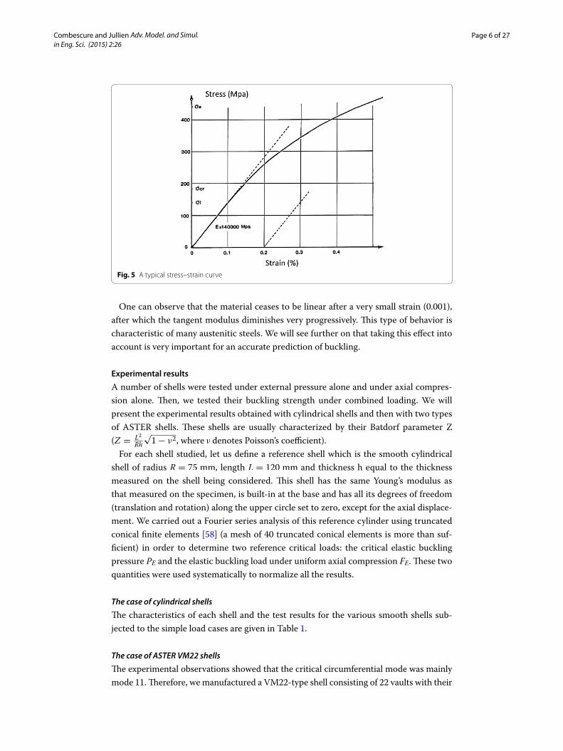
The material properties were measured for each specimen. In order to do that, a ten-sile test piece was cut out of scrap material from a specimen and used to determine the Young’s modulus and nonlinear properties (see Fig. 5).
Fig. 4 A typical post‑buckling geometry
Page 6 of 27Combescure and Jullien Adv. Model. and Simul. in Eng. Sci. (2015) 2:26
One can observe that the material ceases to be linear after a very small strain (0.001), after which the tangent modulus diminishes very progressively. This type of behavior is characteristic of many austenitic steels. We will see further on that taking this effect into account is very important for an accurate prediction of buckling.
Experimental results
A number of shells were tested under external pressure alone and under axial compres-sion alone. Then, we tested their buckling strength under combined loading. We will present the experimental results obtained with cylindrical shells and then with two types of ASTER shells. These shells are usually characterized by their Batdorf parameter Z (Z =
L2
Rh
√1− ν2, where ν denotes Poisson’s coefficient).
For each shell studied, let us define a reference shell which is the smooth cylindrical shell of radius R = 75 mm, length L = 120 mm and thickness h equal to the thickness measured on the shell being considered. This shell has the same Young’s modulus as that measured on the specimen, is built-in at the base and has all its degrees of freedom (translation and rotation) along the upper circle set to zero, except for the axial displace-ment. We carried out a Fourier series analysis of this reference cylinder using truncated conical finite elements [58] (a mesh of 40 truncated conical elements is more than suf-ficient) in order to determine two reference critical loads: the critical elastic buckling pressure PE and the elastic buckling load under uniform axial compression FE. These two quantities were used systematically to normalize all the results.
The case of cylindrical shells
The characteristics of each shell and the test results for the various smooth shells sub-jected to the simple load cases are given in Table 1.
The case of ASTER VM22 shells
The experimental observations showed that the critical circumferential mode was mainly mode 11. Therefore, we manufactured a VM22-type shell consisting of 22 vaults with their
Fig. 5 A typical stress–strain curve

Page 7 of 27Combescure and Jullien Adv. Model. and Simul. in Eng. Sci. (2015) 2:26
concavity pointed inward. The depth d of the vaults was equal to 2.32 mm, which corre-sponds to a radius of curvature r equal to 20 mm. Such an amplitude leads to a “hump” amplitude between 4 and 5 times the shell’s nominal thickness. Table 2 below summarizes the various tests and gives the buckling loads of the elementary loading cases. The loading cases are normalized to the linear elastic buckling load of the smooth cylinder with the same radius, height, thickness and material. We found that the ASTER VM22 shells were four times more resistant to external pressure than the corresponding smooth shells and that the theoretical critical load of the reference cylinder associated with the shell being studied could be reached thanks to the vaults. Thus, these vaults have a beneficial effect for all the loading cases and are very effective against external pressure.
Table 1 Characteristics of the cylinders and experimental buckling loads
External pressure A1 A2 A3 A4
h (µm) 150 150 154 158
R/h 500 500 487 475
Z 1220 1220 1190 1160
E (GPa) 162 155 158 152
Pexp Buckling pressure (MPa) 0.021 0.019 0.020 0.0223
PE (MPa) 0.0213 0.0204 0.0222 0.0227PexpPE
0.986 0.931 0.900 0.982
Fourier mode n 11 10 11 11
Axial compression A5 A6
h (µm) 150 148
R/h 500 500
Z 1220 1933
E (GPa) 163 155
Fexp Buckling load (N) 11,000 9275
FE (N) 14,193 13,125FexpFE
0.775 0.707
Fourier mode n 11 12
Table 2 ASTER VM22 shells: characteristics and experimental buckling loads
External pressure B1 B2 B3* B4*
h (µm) 152 155 150 150
R/h 493 484 500 500
E (GPa) 147 161 164 167.5
Pexp Buckling pressure (MPa) 0.091 0.092 0.070 0.072
PE (MPa) 0.0190 0.0230 0.0216 0.0220PexpPE
4.57 4.00 3.24 3.27
Axial compression B5 B6
h (µm) 153 150
R/h 490 500
E (GPa) 162 163
Fexp Buckling Load (N) 14,400 13,200
FE (N) 14,200 14,067FexpFE
1.01 0.94

Page 8 of 27Combescure and Jullien Adv. Model. and Simul. in Eng. Sci. (2015) 2:26
Remark the critical loads of shells B3 and B4 under external loading are marked with an * because these two shells were subjected to about ten external pressure cycles at two-thirds of the expected critical load prior to continuing all the way through failure by buckling. This pre-cycling reduces the critical load without cycling by about 25 %. We will return to this point in the discussion of the numerical simulation and explain this observation.
Figure 6 shows a post-critical geometry in the case of external pressure loading alone.
The case of ASTER VM14 shells
In order to study the effect of the choice of the ASTER geometry on the increase in the criti-cal load, we also manufactured ASTER VM14 shells with p = 14 vaults along the circumfer-ence. The depth d of these vaults was 2.35 mm, which corresponds to a radius of curvature r equal to 35 mm. These shells were tested only under simple loading. Table 3 summarizes
Fig. 6 A typical VM22 post‑buckled state
Table 3 ASTER VM14 shells: characteristics and experimental buckling loads
External pressure C1 C2
h (µm) 149 147
R/h 503 510
E (GPa) 154 143
Pexp Buckling pressure (MPa) 0.054 0.045
PE (MPa) 0.020 0.018PexpPE
2.7 2.6
Axial compression C3 C4
h (µm) 150 148
R/h 500 507
E (GPa) 151 156.5
Fexp Buckling Load (N) 6200 5100
FE (N) 12937 13,012FexpFE
0.48 0.39

Page 9 of 27Combescure and Jullien Adv. Model. and Simul. in Eng. Sci. (2015) 2:26
the experimental results. One can immediately see that this type of vault is less effective under external pressure and cuts the critical load under axial compression in half.
A post-critical geometry under external pressure is shown in Fig. 7.
The effects of loading combinations on buckling
This section presents the effects of an interaction between loading cases on buckling for the first two shell types. In the case of combined loads, we increased the applied pressure and the axial compression load simultaneously. These two loading cases were apportioned to the reference linear buckling loads for the cylinder being considered. The results for smooth cylinders are given in Table 4.
The results for VM22 shells are given in Table 5.These results will be interpreted later with the presentation of the calculation results.
Discussion of the experimental results
The sum of these experimental results shows the interest of ASTER type shells in increasing buckling strength. One can see that the choice of the number of vaults plays an important role in the quality of the buckling strength. This type of shell, which can
Fig. 7 A typical VM14 post‑buckled state
Table 4 Buckling under combined loading: characteristics of the cylinders and experimen‑tal buckling loads
Specimen h (μm) E (GPa) Pexp (MPa) Pexp (N) PE (MPa) FE (N) Load ratio FPEFEP
A1 150 163 0.021 0.000 0.0213 14,111 0
A7 142 150 0.015 2000 0.0173 11,718 4
A8 145 163 0.016 4500 0.0197 13,276 8
A9 138 159 0.0131 3900 0.0171 11,737 8
A10 148 155 0.012 6700 0.0197 13,150 16
A11 139 156 0.0075 6800 0.0171 11,681 26
A12 148 155 0.0078 7200 0.0197 13,150 26
A13 137 160 0.0045 7800 0.0169 11,643 50
A5 150 163 0.000 11,000 0.0214 14,193 ∞

Page 10 of 27Combescure and Jullien Adv. Model. and Simul. in Eng. Sci. (2015) 2:26
be manufactured easily, enables the resistance to buckling under external pressure to be quadrupled and makes the shell quasi-insensitive to imperfections under axial compres-sion. This result is verified experimentally provided one chooses a number of vaults p equal to twice the critical number of circumferential waves in buckling (n). We will now attempt to understand why by means of a numerical simulation of these tests. Then, we will try to find a way to improve this design even further: in order to do that, we will attempt to predict the critical loads for a range of values of p through calculations. Thus, we will seek the existence of an optimum p for this type of shell subjected to combined load cases.
The finite element modelIn this section, we undertake to model these tests using finite elements and compare the experimental results with these numerical simulations.
Perfect cylindrical shells and ASTER shells
First, we carried out two-node axisymmetric or quasi-axisymmetric finite element calcu-lations of the smooth shells (using COMU axisymmetric elements with non-axisymmet-ric modal imperfections), then 3D calculations of the ASTER shells using DKT elements. In the latter case, a half-shell was meshed for each calculation. The base was built-in and the top of the cylinder was left free to dilate vertically. The remaining degrees of freedom of the circle were fixed. All the calculations were performed using the nonlinear finite element code Stanlax [58].
The types of analyses performed
For each cylinder, we first performed an elastic buckling analysis. Then we carried out different analyses depending on the case. For the smooth cylinders, we performed incremental, geometrically nonlinear axisymmetric analyses with elastic or elastic-plastic behavior. We tested the possible loss of stability of the equilibrium thus obtained through a plastic bifurcation analysis on the Fourier modes [58]. For the 3D shells, we simply carried out a linear stability analysis followed by incremental, geometrically non-linear, elastic and elastic-plastic analyses. We also tested the stability after each step of the nonlinear calculations. For all these calculations, we performed a convergence analysis. We found that 40 axisymmetric elements are more than sufficient for the criti-cal loads to converge, and that 40 elements along the axis and 20 elements along the
Table 5 Buckling under combined loading: experimental buckling loads for VM22 ASTER shells
Specimen h (μm) E (GPa) Pexp (MPa) Fexp (N) PE (MPa) FE (N) Load ratio FFE
PEP
B2 150 161 0.0920 0 0.023 14,004 0
B7 142 160 0.0543 2500 0.0184 12,314 0.7
B8 140 148 0.0380 4500 0.0164 11,053 1.4
B9 140 160 0.0326 7900 0.0177 11,951 1.8
B10 152 163 0.0205 14,840 0.0221 14,337 3.5
B5 153 162 0.000 14,200 0.0224 14,200 ∞

Page 11 of 27Combescure and Jullien Adv. Model. and Simul. in Eng. Sci. (2015) 2:26
circumference are needed for the 3D calculation of each ASTER vault (which comes to 1600 DKT elements for each vault). The choice of the model for the nonlinear traction curve was important. We chose the same yield stress σy = 150MPa for all the calcula-tions. The elastic-plastic behavior was given by the reference curve of Fig. 5. The initial plastic strain was calculated by dividing the yield stress by the Young’s modulus. The base of the cylinder was built-in for all the calculations. All the degrees of freedom of the upper circle were fixed, except for the axial displacement. This choice is consistent with the control of the experiments which nullified the end load associated with the pressure.
Results of the calculations and comparison with the experimental resultsThis section presents the results of the simulations and compares them to the experi-mental results.
Cylindrical shells
Let Pexp and Fexp be respectively the experimental buckling pressure in MPa and the experimental axial buckling load in N. PE and FE denote respectively the calculated lin-ear elastic buckling pressure (taking into account the following forces and the axial com-pression load leading to Euler buckling). PNL and PNLP denote respectively the nonlinear elastic and nonlinear plastic buckling pressure. F is the axial compression load. The plas-tic buckling loads were calculated using the tangent modulus theory.
The case of perfect shells
This section concerns simple external pressure or axial compression loading. The results of the calculations for perfect structures are compared to the experimental results for smooth cylinders A1–A6 in Table 6.
First, let us analyze the buckling pressure predictions. The linear buckling calculations predicted the experimental critical loads with less than 10 % error in all cases. In two
Table 6 Perfect cylinders: experimental and calculated buckling loads
External pressure A1 A2 A3 A4
Pexp 0.021 0.019 0.020 0.0223
Fourier mode nexp 11 10 11 11PexpPE
0.986 0.931 0.900 0.982
Fourier mode nE 11 11 11 11PexpPNL
0.991 0.920 0.900 0.982
PexpPNLP
0.991 0.920 0.900 0.982
Axial compression A5 A6
Fexp 11,000 9275
Fourier mode nexp 11 12FexpFE
0.775 0.707
Fourier mode nE 2–15 2–15FexpFNL
0.648 0.708
FexpPNLP
1.01 0.919

Page 12 of 27Combescure and Jullien Adv. Model. and Simul. in Eng. Sci. (2015) 2:26
cases, the experimental load was predicted within less than 3 %. Buckling occurred in the elastic domain. There was no nonlinear pre-buckling effect.
The buckling calculations under axial compression clearly establish that plasticity is responsible for the experimental load being 30 % less than the Euler load. In the case of pure axial compression, we found the same results as in the literature: a large num-ber of Fourier modes correspond to the same critical load. The buckling modes for Fou-rier modes 0 and 11 are given in Fig. 8. Under uniform axial compression, the cylinder always buckles on mode 11. The corresponding shape is shown in Fig. 9.
Influence of initial imperfections
One can also consider the influence of initial imperfections on the critical load. In order to do that, we added an initial imperfection to the perfect geometry in the shape of the elastic buckling mode with amplitude δ. Three cases were calculated (δh = 0.2, 0.1 and 0.01). The largest amplitude corresponds to the maximum imperfection measured on the specimens tested. The calculations were performed with COMU elements, which are specifically adapted to this approach [59]: the imperfection was monomodal on Fourier mode 11, and the response was decomposed according to Fourier modes 0, 11, 22 and 33. Plasticity was evaluated at 21 points along the circumference. Table 7 sum-marizes the results of the geometric and material nonlinear calculations for the three
Fig. 8 Buckling modes under axial compression

Page 13 of 27Combescure and Jullien Adv. Model. and Simul. in Eng. Sci. (2015) 2:26
imperfection amplitudes. Plasticity was not activated in the case of pressure loading, but only for axial compression.
These results show that with an amplitude of initial modal imperfections less than 20 % of the thickness (which is consistent with our experiments) the calculations match the experimental results.
Load interaction diagrams
Let us now address the interactions between loading cases. In order to do that, we con-sider a reference shell with Young’s modulus 160,000 Mpa and thickness 150 μm. With this cylinder, elastic buckling occurs at an external pressure PE equal to 0.02103 MPa, and at an axial compression load equal to 13,961 N. We calculated the linear, elastic non-linear and elastic-plastic nonlinear critical loads for six loading combinations. We also calculated the elastic-plastic nonlinear response with a modal imperfection parallel to the buckling mode shape under external pressure and an amplitude equal to 10 or 1 % of the thickness for each case. Very similar results were obtained with a imperfection of the same amplitude, but parallel to the buckling mode under axial compression. Table 8 summarizes all the calculations. In this Table, �E is the multiplying coefficient of the
Fig. 9 Buckling modes of a cylinder under external pressure
Table 7 Imperfect cylinders: experimental and calculated buckling loads
External pressure A1 A2 A3 A4
PexpPNLP
0.991 0.920 0.900 0.982
PexpPNLPCOMU
;δ
h= 0.01 0.986 0.879 0.920 1.00
PexpPNLPCOMU
;δ
h= 0.1 1.06 0.937 0.985 1.069
PexpPNLPCOMU
;δ
h= 0.2 1.15 0.994 1.04 1.129
Axial compression A5 A6
FexpPNLP
1.01 0.919
FexpFNLPCOMU
;δ
h= 0.01 1.076 0.922
FexpFNLPCOMU
;δ
h= 0.1 1.080 0.988
FexpFNLPCOMU
;δ
h= 0.2 1.087 0.996

Page 14 of 27Combescure and Jullien Adv. Model. and Simul. in Eng. Sci. (2015) 2:26
applied loading combination which leads to Euler buckling. Similarly, �NL and �NLP are the multiplying coefficients which lead to elastic and plastic nonlinear buckling, respec-tively. Coefficients �defa=0.01 and �defa=0.1 are the multiplying coefficients leading to the elastic-plastic buckling load for an initial imperfection of amplitude 0.01 and 0.1 % of the thickness, respectively. These are compared with the experimental results obtained for shells A1, A5 and A7–A13. All these results are normalized to the Euler pressure in abscissa and the Euler axial compression load in ordinate. Table 9 gives the normalized experimental results. Figure 10 shows a comparison between the interaction diagram obtained from the calculations and the experimental data.
This figure shows good agreement between calculations and experimental results con-cerning the interaction diagram. In the case of significant axial compression loads, as noted previously, plasticity plays an important role. Conversely, it does not affect exter-nal pressure loading. All the interaction curves are convex. Therefore, a linear interac-tion is conservative, provided the critical load reduction effects on axial compression (plasticity) and on external pressure (geometric imperfections) are taken into account. For these tests, the calculations with an amplitude of initial modal imperfection equal to 10 % of the thickness lead to a good estimate of the experimental critical load in all the cases.
The case of ASTER VM22 shells
In this section, we focus on the prediction of the critical load for ASTER VM22 shells (22 outward vaults). The results of the calculations for the “perfect” structure under simple
Table 8 Buckling under combined loading: calculated ratios under various modeling assumptions
Pressure load ratio Axial load ratio �E �NL �NLP �δ = 0.01 �δ = 0.1
0.0 1.0 1.00 0.994 0.756 0.724 0.71
0.2 0.8 1.17 1.171 0.944 0.960 0.895
0.4 0.6 1.18 1.186 1.186 1.161 1.06
0.6 0.4 1.14 1.146 1.146 1.107 1.102
0.8 0.2 1.07 1.078 1.078 1.042 0.97
1.0 0.0 1.00 1.01 1.01 0.99 0.92
Table 9 Buckling under combined loading: Euler loads and experimental ratios
Specimen PE (MPa) FE (N) PexpPE
FexpFE
A1 0.0210 14,111 0.99 0.021
A7 0.01725 11,718 0.87 0.17
A8 0.01972 13,276 0.81 0.34
A9 0.01707 11,737 0.76 0.33
A10 0.01971 13,150 0.61 0.51
A11 0.01704 11,680 0.44 0.58
A12 0.01971 13,150 0.40 0.55
A13 0.0169 11,643 0.27 0.67
A5 0.0214 14,193 0.00 0.77

Page 15 of 27Combescure and Jullien Adv. Model. and Simul. in Eng. Sci. (2015) 2:26
pressure loading for shells B1 and B2 and under uniform axial compression for shell B5 are compared to the experimental results in Table 10.
The calculated predictions match the experimental results very well when plasticity is taken into account. The nonlinear elastic calculations systematically overestimate the critical loads. Two calculated buckling deformed shapes (under axial compression and under external pressure) are presented in Fig. 11. Now let us address combined loading. These cases concern the experiments on shells B1, B2, B7, B8, B9, B10 and B5. The theo-retical loads are normalized to the Euler loads of the corresponding perfect cylindrical shells. The theoretical critical loads under combined loading were calculated with the same properties as the reference shell (Young’s modulus 160,000 Mpa and thickness 150 μm, as in the case of smooth cylinders) and divided by the elastic buckling loads of the same shell (Table 11).
The calculation results are given in Table 12.The results of the various calculations are compared with the experimental results in
Fig. 12.
Fig. 10 Cylinders under combined loading (experiments and calculations): interaction diagram
Table 10 ASTER VM22 shells: comparison of the calculated and experimental buckling loads
Specimen Loading type Experimental buckling load �exp
�E
�exp
�NL
�exp
�NLP
B1 Pressure 0.091 MPa 4.57 0.58 1.01
B2 Pressure 0.092 MPa 4.00 0.512 0.98
B5 Axial load 14,200 N 0.99 0.84 1.03

Page 16 of 27Combescure and Jullien Adv. Model. and Simul. in Eng. Sci. (2015) 2:26
One can observe that in most cases a calculation based on linear elastic analysis is not predictive. The comparison with geometrically nonlinear calculations is even worse: in this case, the geometric nonlinearities have a stiffening effect. The only predictive cal-culation is the one which takes plasticity into account. This effect is drastic in almost all the cases: plasticity reduces the critical load by about one-third. In this type of stiffening effect, plasticity always plays an important role.
Fig. 11 ASTER VM22 buckling modes
Table 11 ASTER VM22 shells: experimental buckling loads under combined loading
Specimen PE (MPa) FE (N) PcrexpPE
FcrexpFE
B1 0.0199 13,171 4.57 0.00
B2 0.023 14,972 4.00 0.00
B7 0.0184 12,315 2.95 0.20
B8 0.0164 11,053 2.32 0.41
B9 0.0177 11,951 1.84 0.66
B10 0.0221 14,337 0.93 1.04
B5 0.021 14,400 0 1.01
B6 0.021 14,119 0 0.99

Page 17 of 27Combescure and Jullien Adv. Model. and Simul. in Eng. Sci. (2015) 2:26
The case of ASTER VM14 shells
In this section, we focus on the numerical prediction of the tests for 14-vaulted shells. The results of the 3D calculations are compared to the experimental results in Table 13. Figure 13 shows the two elastic buckling modes. In this case in which the vaults lead to a less significant gain in critical load, the geometrically nonlinear predictions are good for the first three shells. The addition of plasticity slightly improves the results. For shell C4,
Table 12 ASTER VM22 shell buckling under combined loading: calculated ratios under various modeling assumptions
Pressure load ratio Axial load ratio �E �NL �NLP
0.0 1.0 1.60 0.95 0.84
0.1 0.9 1.79 1.65 1.29
0.2 0.8 2.03 1.80 1.36
0.3 0.7 2.33 1.98 1.45
0.4 0.6 2.75 2.27 1.57
0.5 0.5 2.95 2.48 1.74
0.6 0.4 3.06 2.83 1.95
0.7 0.3 3.12 3.31 2.23
0.8 0.2 3.16 3.92 2.60
0.9 0.1 3.29 5.00 3.08
1.0 0.0 3.31 5.95 4.01
Fig. 12 ASTER VM22 shell under combined loading (experiments and predictions): interaction diagram

Page 18 of 27Combescure and Jullien Adv. Model. and Simul. in Eng. Sci. (2015) 2:26
which is subjected to axial compression, the predictions exceed the experimental critical load by 20 %.
Influence of imperfections
The previous results concerned multi-vaulted shells without imperfections. The next question is that of the influence of possible shape imperfections on the critical load. We performed a series of calculations to evaluate the influence of initial imperfections on buckling. In order to do that, we created an imperfect shell by adding to the initial perfect (multi-vaulted) geometry an imperfection, parallel to the elastic buckling mode under external pressure, with an amplitude of 10 % of the thickness. Then we calculated the elastic-plastic nonlinear critical loads under uniform axial compression and under
Fig. 13 ASTER VM14 buckling modes
Table 13 ASTER VM14 shells: comparison of the calculated and experimental buckling loads
Specimen Loading type Experimental buckling load �exp
�E
�exp
�NL
�exp
�NLP
C1 Pressure 0.054 MPa 2.7 0.99 0.93
C2 Pressure 0.046 MPa 2.6 0.85 0.87
C3 Axial load 6200 N 0.48 0.97 1.0
C4 Axial load 5100 N 0.39 0.78 0.83

Page 19 of 27Combescure and Jullien Adv. Model. and Simul. in Eng. Sci. (2015) 2:26
uniform external pressure for shells VM14 and VM22. The reductions observed in the critical loads did not exceed 3 %. We obtained similar results with an imperfection paral-lel to the buckling mode under axial compression. This led to the conclusion that these shells are relatively insensitive to initial imperfections, both in the case of axial compres-sion and in the case of external pressure.
Discussion
We found that vaults lead to a significant increase in the buckling strength under uni-form external pressure and also improve the resistance to axial compression. This type of shell is relatively insensitive to initial imperfections. The choice of the number of vaults also plays a role. The effect becomes significant once the number of vaults equals twice the Fourier buckling mode of the smooth cylinder under external pressure. The question then arises of the optimal choice of the number and depth of the vaults with regard to buckling strength under combined loading. This is the subject of the next section.
The optimization procedureWe carried out a systematic study of the effect of the number and depth of the vaults on the buckling strength under external pressure alone, under axial compression alone and, finally, under combined loading with 50 % of the critical axial compression and 50 % of the critical external pressure. In order to do that, we first assumed a constant vault depth d. We used the reference shell (Young’s modulus 160,000 MPa and thickness 150 μm).
Influence of the number of vaults p
Under external pressure alone
The results of the linear elastic, nonlinear elastic and elastic-plastic calculations are given in Fig. 14. One can observe that the critical loads increase very rapidly beyond mode 10 (which corresponds to 20 vaults) and reach a factor 4. Then, they continue to increase progressively with the number of vaults to reach a factor greater than 10 for 60 vaults. Let us note that, in this case, the nonlinear elastic estimates are very optimistic. Plasticity plays a significant role once the number of vaults exceeds 20. Beyond 50 vaults, the critical load reaches a maximum of 10 times the Euler load.
Under axial compression alone
The results of the calculations are given in Fig. 15.ASTER shells are less effective in terms of resisting axial compression. Nevertheless,
beyond 20 vaults, the critical load is multiplied by two. Then it increases progressively with the number of vaults and reaches the Euler load for 80 vaults. In this case, taking nonlinearities into account leads to a significant decrease in the predicted critical load. Plasticity reduces it by about another 10 %.
Under combined loading (50 % axial compression, 50 % external pressure)
The results of the calculations are given in Fig. 16.For this loading combination, the linear and nonlinear elastic predictions are
quite similar, but very optimistic. Taking plasticity into account plays a decisive role.

Page 20 of 27Combescure and Jullien Adv. Model. and Simul. in Eng. Sci. (2015) 2:26
Fig. 14 ASTER VM shells: influence of the number of vaults on the buckling pressure
Fig. 15 ASTER VM shells: influence of the number of vaults on the axial compression buckling load

Page 21 of 27Combescure and Jullien Adv. Model. and Simul. in Eng. Sci. (2015) 2:26
However, one can observe that beyond 20 vaults the critical load is multiplied by two, then decreases by a maximum of 20 %.
Influence of the vault depth d
In this section, we study how the vault depth affects the improvement brought about by outward vaults. This presentation is limited to ASTER VM22 shells. We considered sev-eral ratios of the vault depth to the thickness of the shell. The evolution of the radius of curvature of the vault as a function of this ratio is shown in Fig. 17.
The calculation results for external pressure loading alone are given in Fig. 18. One can observe an improvement factor between 5 and 6 when the ratio d/h becomes greater than 7.5. First, the nonlinear critical loads are greater than the linear critical loads. Plas-ticity limits the effectiveness of the shell when the ratio exceeds 10.
Figures 19 and 20 show similar tendencies for axial loading and combined 50 % exter-nal pressure and 50 % axial compression loading. The nonlinear elastic and elastic-plas-tic critical loads become less than the Euler load when the vault depth exceeds 10 times the thickness.
Based on these results, we can conclude that the recommended vault depth is about 10 times the thickness.
Fig. 16 ASTER VM shells: influence of the number of vaults on buckling under combined loading

Page 22 of 27Combescure and Jullien Adv. Model. and Simul. in Eng. Sci. (2015) 2:26
Fig. 17 ASTER VM22 shells: the relative vault depth as a function of the vault radius r
Fig. 18 ASTER VM22 shells: influence of the relative vault depth on the buckling load under external pressure

Page 23 of 27Combescure and Jullien Adv. Model. and Simul. in Eng. Sci. (2015) 2:26
Fig. 19 ASTER VM22 shells: influence of the relative vault depth on the buckling load under axial compres‑sion
Fig. 20 ASTER VM22 shells: influence of the relative vault depth on the buckling load under combined load‑ing
Page 24 of 27Combescure and Jullien Adv. Model. and Simul. in Eng. Sci. (2015) 2:26
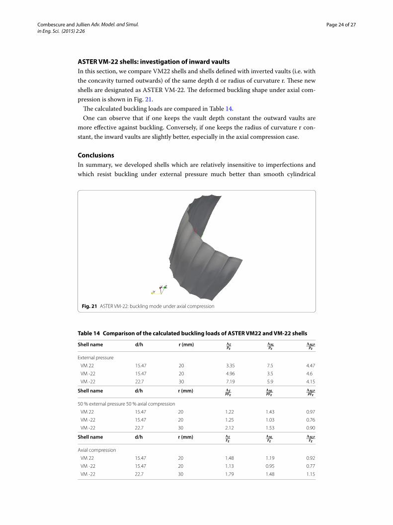
ASTER VM‑22 shells: investigation of inward vaultsIn this section, we compare VM22 shells and shells defined with inverted vaults (i.e. with the concavity turned outwards) of the same depth d or radius of curvature r. These new shells are designated as ASTER VM-22. The deformed buckling shape under axial com-pression is shown in Fig. 21.
The calculated buckling loads are compared in Table 14.One can observe that if one keeps the vault depth constant the outward vaults are
more effective against buckling. Conversely, if one keeps the radius of curvature r con-stant, the inward vaults are slightly better, especially in the axial compression case.
ConclusionsIn summary, we developed shells which are relatively insensitive to imperfections and which resist buckling under external pressure much better than smooth cylindrical
Fig. 21 ASTER VM‑22: buckling mode under axial compression
Table 14 Comparison of the calculated buckling loads of ASTER VM22 and VM‑22 shells
Shell name d/h r (mm) �E
PE
�NL
PE
�NLP
PE
External pressure
VM 22 15.47 20 3.35 7.5 4.47
VM ‑22 15.47 20 4.96 3.5 4.6
VM ‑22 22.7 30 7.19 5.9 4.15
Shell name d/h r (mm) �E
PFE
�NL
PFE
�NLP
PFE
50 % external pressure 50 % axial compression
VM 22 15.47 20 1.22 1.43 0.97
VM ‑22 15.47 20 1.25 1.03 0.76
VM ‑22 22.7 30 2.12 1.53 0.90
Shell name d/h r (mm) �E
FE
�NL
FE
�NLP
FE
Axial compression
VM 22 15.47 20 1.48 1.19 0.92
VM ‑22 15.47 20 1.13 0.95 0.77
VM ‑22 22.7 30 1.79 1.48 1.15

Page 25 of 27Combescure and Jullien Adv. Model. and Simul. in Eng. Sci. (2015) 2:26
shells. Their axial compression strength is also better. These results require the use of a number of vaults at least equal to twice the Fourier mode number of the critical buckling mode of the smooth cylinder under external pressure. The recommended vault depth d is at least ten times the thickness. In addition, these shells are relatively insensitive to initial imperfections, which is an important advantage over the reference smooth cylin-ders. This type of shell can be manufactured relatively easily. The choice of vaults with their concavity turned inward seems to be slightly better when external pressures are predominant. The conclusions given in the paper take into account the load reduction effects due to plasticity, which play a significant role (all the more so when the stiffening effect is high). Therefore, one could improve the buckling strength of this type of shell much further by choosing materials with a high yield strength.Authors’ contributionsJFJ as provided the experimental results. AC has developped the FEM softwareand done all the computations. Both authors have read and approved the final manuscript.
Author details1 SAFRAN‑AREVA‑Chair, LaMCoS UMR CNRS 5259, INSA‑LYON, Universite de Lyon, 61 AV President Wilson, 69621 Villeur‑banne, France. 2 LaMCoS UMR CNRS 5259, INSA‑LYON, Universite de Lyon, 61 AV President Wilson, 69621 Villeurbanne, France.
Competing interestsThe authors declare that they have no competing interests.
Received: 11 June 2015 Accepted: 1 October 2015
References 1. Donnell LH. A new theory for the buckling of thin cylinders under axial compression and bending. Trans ASME.
1934;56(11):795–806. 2. Windenburg DF, Trilling C. Collapse by instability of thin cylindrical shells under external pressure. Trans ASME.
1934;56(11):819. 3. Yoshimura Y. On the mechanism of buckling of a circular cylindrical shell under axial compression. Technical report.
1951. 4. Tennyson R. A note on the classical buckling load of circular cylindrical shells under axial compression. AIAA J.
1963;1(2):475. 5. Almroth B. Postbuckling behavior of axially compressed circular cylinders. AIAA J. 1963;1(3):630–3. 6. Almroth B, Holmes A, Brush D. An experimental study of the bucking of cylinders under axial compression. Exp
Mech. 1964;4(9):263–70. 7. Hoff NJ, Madsen WA, Mayers J. Postbuckling equilibrium of axially compressed circular cylindrical shells. AIAA J.
1966;4(1):126–33. 8. Tennyson R. Buckling modes of circular cylindrical shells under axial compression. AIAA J. 1969;7(8):1481–7. 9. Yamaki N. Influence of prebuckling deformations on the buckling of circular cylindrical shells under external pres‑
sure. AIAA J. 1969;7(4):753–5. 10. Yamaki N, Otomo K. Experiments on the postbuckling behavior of circular cylindrical shells under hydrostatic pres‑
sure. Exp Mech. 1973;13(7):299–304. 11. Miller CD. Buckling of axially compressed cylinders. J Struct Div. 1977;103(3):695–721. 12. Andrews K, England G, Ghani E. Classification of the axial collapse of cylindrical tubes under quasi‑static loading. Int
J Mech Sci. 1983;25(9):687–96. 13. Yamaki N. Elastic stability of circular cylindrical shells. In: Beckers A, Budianski B, Lauwerier HA, Koiter T, editors. North
Holland Series in applied Mathematics and Mechanics. North Holland: Elsevier; 1984. 14. Bushnell D. Computerized buckling analysis of shells. Mechanics of elastic stability, vol 9. Netherlands: Springer;
1985. 15. Teng J‑G, Rotter JM. Buckling of pressurized axisymmetrically imperfect cylinders under axial loads. J Eng Mech.
1992;118(2):229–47. 16. Mandal P, Calladine C. Buckling of thin cylindrical shells under axial compression. Int J Solids Struct.
2000;37(33):4509–25. 17. Stein M. Some recent advances in the investigation of shell buckling. J Spacecr Rockets. 2003;40(6):908–14. 18. Rotter J. Cylindrical shells under axial compression. In: Teng JG, RotterM, editors. Buckling of thin metal shells. Lon‑
don: Spon; 2004. p. 42–87 19. Von Karman T. The buckling of thin cylindrical shells under axial compression. J Aeronaut Sci (Institute of the Aero‑
nautical Sciences). 1941;8(8):303–13.

Page 26 of 27Combescure and Jullien Adv. Model. and Simul. in Eng. Sci. (2015) 2:26
20. Kempner J. Postbuckling behavior of axially compressed circular cylindrical shells. J Aeronaut Sci (Institute of the Aeronautical Sciences). 1954;21(5):354–63.
21. Donnell L, Wan C. Effect of imperfections on buckling of thin cylinders and columns under axial compression. J Appl Mech Trans ASME. 1950;17(1):73–83.
22. Donnell L. Effect of imperfections on buckling of thin cylinders under external pressure. J Appl Mech. 1956;23(4):569–75.
23. Gerard G. On the role of initial imperfections in plastic buckling of cylinders under axial compression. Aerospace Sci. 1962;29(6):744–5.
24. Sobel L. Effects of boundary conditions on the stability of cylinders subject to lateral and axial pressures. AIAA J. 1964;2(8):1437–40.
25. Hutchinson JW. Imperfection sensitivity of externally pressurized spherical shells. J Appl Mech. 1967;34(1):49–55. 26. Arbocz J, Babcock CD. The effect of general imperfections on the buckling of cylindrical shells. J Appl Mech.
1969;36(1):28–38. 27. Muggeridge D, Tennyson R. Buckling of axisymmetric imperfect circular cylindrical shells under axial compression.
AIAA J. 1969;7(11):2127–31. 28. Hutchinson J, Koiter W. Postbuckling theory. Appl Mech Rev. 1970;23(12):1353–66. 29. Hutchinson J, Muggeridge D, Tennyson R. Effect of a local axisymmetric imperfection on the buckling behaviorof a
circular cylindrical shell under axial compression. AIAA J. 1971;9(1):48–52. 30. Amazigo JC, Budiansky B. Asymptotic formulas for the buckling stresses of axially compressed cylinders with local‑
ized or random axisymmetric imperfections. J Appl Mech. 1972;39(1):179–84. 31. Sheinman I, Simitses GJ. Buckling analysis of geometrically imperfect stiffened cylinders under axial compression.
AIAA J. 1977;15(3):374–82. 32. Sheinman I, Simitses G. Buckling and postbuckling of imperfect cylindrical shells under axial compression. Comput
Struct. 1983;17(2):277–85. 33. Simitses GJ. Buckling and postbuckling of imperfect cylindrical shells: a review. Appl Mech Rev. 1986;39(10):1517–24. 34. Rotter JM, Teng J‑G. Elastic stability of cylindrical shells with weld depressions. J Struct Eng. 1989;115(5):1244–63. 35. Calladine C. Understanding imperfection‑sensitivity in the buckling of thin‑walled shells. Thin Wall Struct.
1995;23(1):215–35. 36. Guggenberger W. Buckling and postbuckling of imperfect cylindrical shells under external pressure. Thin Wall Struct.
1995;23(1):351–66. 37. Gusic G, Combescure A, Jullien J. The influence of circumferential thickness variations on the buckling of cylindrical
shells under external pressure. Comput Struct. 2000;74(4):461–77. 38. Batterman SC. Plastic buckling of axially compressed cylindrical shells. AIAA J. 1965;3(2):316–25. 39. Gellin S. Effect of an axisymmetric imperfection on the plastic buckling of an axially compressed cylindrical shell. J
Appl Mech. 1979;46(1):125–31. 40. Sobel L, Newman S. Plastic buckling of cylindrical shells under axial compression. J Press Vessel Technol.
1980;102(1):40–4. 41. Andronicou A, Walker A. A plastic collapse mechanism for cylinders under uniaxial end compression. J Constr Steel
Res. 1981;1(4):23–34. 42. Hunt GW, Williams K, Cowell R. Hidden symmetry concepts in the elastic buckling of axially‑loaded cylinders. Int J
Solids Struct. 1986;22(12):1501–15. 43. Park T‑D, Kyriakides S. On the collapse of dented cylinders under external pressure. Int J Mech Sci. 1996;38(5):557–78. 44. Bardi F, Kyriakides S. Plastic buckling of circular tubes under axial compression? Part I: experiments. Int J Mech Sci.
2006;48(8):830–41. 45. Bardi F, Kyriakides S, Yun H. Plastic buckling of circular tubes under axial compression? Part II: analysis. Int J Mech Sci.
2006;48(8):842–54. 46. Almroth BO. Influence of edge conditions on the stability of axially compressed cylindrical shells. AIAA J.
1966;4(1):134–40. 47. Shen H‑S, Chen T‑Y. Buckling and postbuckling behaviour of cylindrical shells under combined external pressure
and axial compression. Thin Wall Struct. 1991;12(4):321–34. 48. Ning X, Pellegrino S. Imperfection‑insensitive axially loaded thin cylindrical shells. Int J Solids Struct.
2015;62(1):39–51. 49. Ning X, Pellegrino S. Imperfection‑insensitive axially loaded cylindrical shells. 2013. 54th AIAA/ASME/ASCE/AHS/ASC
structures, structural dynamics and materialsconference, 8–11 April 2013, Boston, MA. Also see joint conference of Society of Engineering Science and ASME‑AMD summer meeting.
50. Waeckel N. Imperfections geometriques initiales et instabilitTs de structures minces. PhD thesis, Universite Claude Bernard Lyon 1. 1984.
51. Waeckel N, Jullien PLJ‑F. Experimental studies on the instability of initial geometrical imperfections. Special Publica‑tion (PVP), San Antonio, TX, USA. 1984;89:69–77.
52. Waeckel N, Cousin M, Combescure A, Carnoy E. Buckling of imperfect cylinders : a synthesis. Special Publication (PVP), San Antonio, TX, USA. 1984;89:78–85.
53. Waeckel, Kabore A, Cousin M, Jullien J‑F. In: Buckling of cylindrical shells, Paper presented in 8th SMIRT Conference (August 1985), SMIRT, vol BL 1/2. Brussels; 1985.
54. Waeckel AK, Jullien J‑F. Buckling of axially compressed imperfect cylinders and ring stiffened cylinders under exter‑nal pressure. In: Wieringa H, editor. Experimental stress analysis, Proceedings of the VIIth international conference. Netherlands: Springer; 1986. p. 123–40.
55. Debbaneh, Jullien J‑F, Reynouard J‑M, Waeckel N. Corrugated cylindrical shells. In: Dubas P, Vandepitte D, editor. Pro‑ceedings of ECCS Colloquium on Stability of Plate and Shell Structurt’s, Ghent University, 6–8 April 1987. p. 477–84.
56. Jullien J‑F, Araar M. Towards an optimal shape of cylindrical shell structure under external pressure. In: Jullien J‑F, editor. Buckling of shell structures, on land, in the sea Air. London: Elsevier applied science. 1991. p. 22–8.

Page 27 of 27Combescure and Jullien Adv. Model. and Simul. in Eng. Sci. (2015) 2:26
57. Limam A, Jullien J‑F, Greco E, Lestrat D. Buckling of thin‑walled cylinders under axial compression and internal pres‑sure. In: Jullien J‑F, editor. Buckling of shell structures, on land, in the sea Air. London: Elsevier applied science. 1991. p. 359–69.
58. Combescure A. Modeling elastic‑plastic buckling of sandwich axisymmetric shells: on the limits of “shell” models and analytical solutions. Adv Model Simul Eng Sci. 2014;1:2.
59. Combescure A. Static and dynamic buckling of large thin shells. Nucl Eng Design. 1986;92:339–54.