ASTAT - ABB Ltd...Resistors E-room losses Air-condition A 2000 A motion control system. ASTAT is by...
14
Crane Motion Controller ASTAT ® Crane Motion Control ASTAT ® Leading edge control for demanding applications
Transcript of ASTAT - ABB Ltd...Resistors E-room losses Air-condition A 2000 A motion control system. ASTAT is by...

Cra
ne M
otio
n C
ontr
olle
r A
STA
T®
Crane Motion Control
ASTAT®
Leading edge control for demanding applications

3
ASTAT®
– Leading edge control for demanding applications
ASTAT® is a highly developed, wellproven system for speed controlledheavy duty motors in industrial cranes. Designed for even the toughest environ-ments ASTAT brings reliable, cost effec-tive crane control into the computer age. Using leading edge computer technology,ASTAT now combines advanced controlfeatures with comprehensive informationand data distribution to enhance performance at all levels.ASTAT is made specially for high utilisation, designed with higher gradecomponents and larger margins than normal industrial drives.
• Robust, well proven thyristor control• Compact, low loss, integrated design• Comprehensive operator information
simply displayed• Fully digital system means no drift in
parameter settings• PC spread-sheet applications for
engineering and equipment management
• Data communications link for monitoring, maintenance and high level automation
• Rapid installation and commissioning• Option packages for advanced functions
Compact, robustand reliable
ASTAT is designed tomeet the demands ofspace conscious crane designers - a control panel for a 1.5 MW hoist is only 1.6 m high and 1.5 m wide.Component designmakes it possible forcranes to operate effectively at high temperatures and in aggressive environments.High quality compo-nents, safety featuresand diagnostic programsmake for a long, reliableoperating life.ASTAT ratings;
Ranges from 25 to 2200 A.Supply voltages from 380 to 600V AC.Temperature to +70° C/+160° F.

4
0
1
2
3
4
5
6
40%
Resistors E-room losses Air-condition
A 2000 A motion control system.
ASTAT is by far the most economical way to control EOTcranes or other installations due to its high quality design, excellent controllability and optimisation for low total installation costs. ASTAT is:
More efficient and reliable
ASTAT operates reliably even at 70 % of nominal line voltage so it is suitable forlocations with a weak power supply.
It is made for many years service in tough environments even at +70° C/160° F.ASTAT is unique as a totally digital motion control system without drift in settingsover this extended temperature range - starting with a Scandinavian winter!
Effective to install
ASTAT uses less space for electrical installation and is lighter than other controlequipment. It needs less ancillary equipment with basic integrated functionslike PTC-relays.
ASTAT imposes less than 0.5 % reduction in voltage for internal power lossesand needs less air conditioning. In most cases it needs no air conditioning at all.
It is not sensitive to type or length of motor cables. The control cables canbe laid together with power and lighting cables without risk of interference.
Easier and cheaper to run
ASTAT has first class torque response and there is no reduction in torque com-pared with a motor connected direct on line. The driver gets a very obedientmotion controller!
As a closed loop speed controlled drive, ASTAT gives speed control inde-pendent of load from zero speed and minimises wear of brakes and contactors.
For hoists and similar applications the lowering energy is recovered and fedto the mains.
Made for automation in tough environments
ASTAT has communication links for integration in overall automation systems.Transducers such as pulse encoders and laser transmitters can be connected toASTAT as is, without additional interfaces.
In this way your crane is already prepared for total automation when you install a stand-alone ASTAT.
Easier to maintain
The simple system is rapidly and easily understood.The built-in fault diagnosis is simple and direct and will speed up emer-
gency repairs. It can also be linked to higher level monitoring system with moreextended functions to permit maintenance scheduling.
ASTAT® – the economical and effective approach to crane control
Energy balance – the key to sustained low running costs. Overall powerloss in an ASTAT system is low and compares favorably with regenerativefrequency converter methods with, in many cases, the added advantage of not needing complicated and expensive climate control.
Losses in different drive systems in a crane hoist
ASTAT
1,600 m
1,500 m
Regenerative with thyristor supplyFrequency Converter
Chopper+Resistor Frequency Converter
5
Cost effective control for industrial crane motors
ASTAT is a well established system of crane motorcontrol using phase control thyristors. It includes allthe usual functions for crane control such as joystickhandling, limit switch logic with slow down andstop, automatic brake application approaching zerospeed and closed loop speed control.
Using a newly developed torque and current regulator, supporting the inherently stable voltagecontrol, ASTAT optimises motor control giving improved crane response and longer component lifeby controlled smooth handling.
Lower energy wastage, longer component life,lower stress on drives and operators mean that ASTATgives you higher availability and better control.
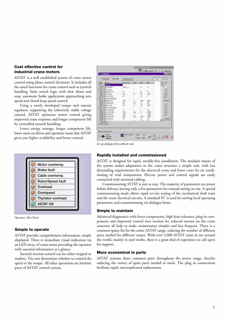
Simple to operate
ASTAT provides comprehensive information, simplydisplayed. There is immediate visual indication viaan LED array, of crane status providing the operatorwith essential information at a glance.
Joystick motion control can be either stepped orstepless. The user determines whether to control thespeed or the torque. All other operations are intrinsicparts of ASTAT control system.
Rapidly installed and commissioned
ASTAT is designed for rapid, trouble-free installation. The modular nature ofthe system makes adaptation to the crane structure a simple task, with less demanding requirements for the electrical room and lower costs for air condi-tioning of vital components. Electric power and control signals are easily connected with minimal cabling.
Commissioning ASTAT is just as easy. The majority of parameters are presetbefore delivery, leaving only a few parameters for manual setting on site. A specialcommissioning mode allows rapid on-site testing of the mechanical shaft trainand the main electrical circuits. A standard PC is used for setting local operatingparameters and commissioning via dialogue boxes.
Simple to maintain
Advanced diagnostics with fewer components, high heat tolerance, plug in com-ponents and improved control over motion for reduced stresses on the cranestructure all help to make maintenance simpler and less frequent. There is acommon spares list for the entire ASTAT range, reducing the number of differentparts needed for different cranes. With over 5,000 ASTAT units in use aroundthe world, mainly in steel works, there is a great deal of experience to call uponfor support.
More economical in parts
ASTAT systems share common parts throughout the power range, thereby reducing the variety of spare parts needed in stock. The plug in connections facilitate rapid, uncomplicated replacement.
Operator’s Alert Panel.
Set up dialogue from software tool.
Motor overtemp.
Brake fault
Cable overtemp.
Rotor/Speed fault
Overload
Overspeed
Thyristor overload
ASTAT OK

6
Inherently stable control...
Td
92%Up
57%Up
38% Down
107% Down
Standstill
Load line
Td
R1
R2
R3
Stand still
Speed
78%
63%
Load line
Torque
100% Voltage
80% Voltage
It all works as a car, ASTAT uses two variables for control:Stator control, corresponding to the accelerator of the car, and the Rotor control, corresponding to the gearbox. To continue this analogy, a good driver will use the brake only in emergency situations and as a parking brake.
As in a modern car, the control system includes extra functions like cruise control (speed regulator) and automaticgearbox (optimisation of rotor characteristic).
Stator control by electronic voltage control regulates the torque from the motor...
The aim is to maintain a desired speed. This is achieved by controlling the motortorque. The peak torque is approximately proportional to the square of the voltage.In the example shown here a voltage reduction from 100 % to 80 % reduces thespeed from 78 % of synchronous speed to 63 %.
By means of a pair thyristors in each phase, the voltage can be reduced step-lessly from full line voltage to zero.
The microprocessor controls the voltage applied to the stator by adjustingthe position of the trigger pulses of the phase control thyristors.
... and changes the direction of the torque
No contactors are needed for reversing.Forward torque direction is achieved by the thyristor-pairs 1, 2 and 3, while
the other direction follows by 1, 4 and 5.Change of direction of torque takes no more than 10 ms.
Rotor control by optimising the resistance gives the motor the right characteristics
Slip-ring motor torque is controllable at any speed by varying the external rotorresistance. In this example speeds 92 % and 57 % up as well as 38 % down areobtained by variation of the resistance only.
When lowering at a speed slightly higher than the motor’s synchronousspeed, in this example 107 % of the synchronous speed, the motor will generateenergy back to the line. When the lowering speed is approaching the synchro-nous speed, the rotor resistor is minimised to R1 and the direction of torque ischanged electronically to act as a motor acting downwards. In the diagram, thisis shown by drawing the lowering load line, Td, for both plug braking and forregenerative lowering.
On earlier generations of ASTAT controllers it was necessary to manuallybalance the motors torque at lowest expected line voltage and the current at normal voltage. The new ASTAT Crane Motion Controller needs no manualadjustment, and reconsiders the best motor characteristic at the momentaryvoltage. The objective is to minimise the motor current.
The number of rotor characteristics is selected depending on the duty. ASTAT supports 1 – 5 characteristics.
L1
L2
L3
1
2
3
~3
Thyristors1, 4 and 5.
Thyristors1, 2 and 3.
L1
L2
L3
1
2
3
~34
5

7
...supported by the latest technology in electronics and control theory
A) The frequency of the rotor voltage is deter-mined by advanced digital filtering. By using theline frequency as a reference, the fundamental compo-nent of the rotor frequency gives the slip of the motor,which gives the speed in digital form. ASTAT usesthe slip-ring motor as a virtual integrated pulsetransmitter. A digital signal processor (DSP) is usedfor the evaluation.B) Knowing the slip of the motor, the shaft powercomponent of the total motor power is known. Thetotal power of the motor is calculated based on ad-vanced measurements of current, ASTAT outputvoltage, active losses in the stator circuit of the mo-tor and vector arithmetic. The slip has already beenconverted to motor speed, so the shaft power of themotor can be transformed to shaft torque. AnotherDSP is used for the torque evaluation.C) The switching of the rotor contactor, if any rotor contactor is used, is very fast. ASTAT uses analgorithm which minimises the stator current of themotor, taking into consideration the momentaryline voltage and required torque.
Using this algorithm, the start up adjustment isreduced, the motor can be used with a less stableline supply and it is easier to use existing resistorswhen revamping.D) The current and torque regulator has a responsetime of 3.3 ms similar to a good DC-drive. Thetorque reversal time is limited to 10 ms which isquite sufficient for cranes and similar motions but onthe ”safe” side to prevent hazardous control situations.E) ASTAT is designed to be an intelligent componentin automation and information systems. ContactABB for more information.F) Remote I/O module for installation in the driver’s cabin. A potentiometer or stepped masterswitch can be used. The Operator’s Alert Panel is apart of the Cabin I/O Module. Today, low cost plasticfibre can be used for distances of at least 150 m.
For low budget installations the master switchcan be connected directly to the Process I/O of theControl System Module, and no Cabin I/O Moduleis required.
Costly switching between the radio-controller relayunit and on-board control is minimised as twoCabin I/O Modules can be used and, simply, a DIof the Control System Module is activated tochange to on board control.
Shared motion control is possible.G) A PC is the natural choice for both setting application parameters in the office and startup/trouble shooting on site.

8
Key data
Control System I/O:
Control System Module DARA 100116 Digital in, 110 V DC8 Digital out4 Motor PTC4 Analogue in, 2 Analogue out2 RS 232 for intelligent transducers1 Pulse transmitter4 Rotor connections for speed feedback/
rotor monitoring1 Opto Master-Follower1 Opto Master-Follower cascade1 RS 232 PC Tool1 RS 485 Computer communication
Cabin I/O Module DAPM 1008 Digital in, 24 V DC8 Digital out for LEDs of Alert Panel2 Analogue in 2 Analogue out
Requirements on PC for setting parameters and start up:
• Min. 1.44 MB 3 1/2” floppy disk drive. CD recommended.
• Windows 95/98 or NT or 2000• CPU: the performance of the logger function
depends on the CPU. Pentium 266 MHz or better recommended.
• Memory: the performance of the logger function depends on the size of memory. 64 MB or more recommended.
• COM1 port of computer, 9 pin D-sub.
Requirements for Motors
Stresses are similar to motors connected direct online. Filters are not necessary for existing motors.New motors can be manufactured with traditionalinsulation.
Electrical data
Control System Modules and Thyristor Modules• Operational voltage (Ue):
380 – 600 V AC 50/60 Hz. 3 phase. Functional range: 70 % .. 110 % Ue
• Operational current (Ie):25 – 1100 (2200) A – 100 % or 60 % cdf, 60 h-1, 2.5 Ie, 6 s.
• Control Supply (Us):115/230 V AC 50/60 Hz. 1 phase. Functional range: 70 % .. 110 % Us
• Control circuit (Uc): 110 V DC supplied internally
Cabin I/O Modules• Control Supply (Us): 24 V DC Functional
range: 70 % .. 110 % Us• Control circuit (Uc): 24 V DC Functional
range: 70 % .. 110 % Uc; Uc can be same as Us
Temperature range
Continuous operation rated ambient temperature:• Control System Modules and Cabin I/O
Modules: +70O C/160O F• Thyristor Modules: +85O C/185O F
Reference Temperature for rated current values• Thyristor Modules: +40O C/105O F or
+50O C/120O F; see the order table
Contamination prevention design
The creep distances required are valid for the microenvironment. For practical reasons it has beenfound less effective to fulfil the requirements by onlymatching distances with the tracking properties ofthe isolators; instead the micro environment hasbeen improved by means of moulding or coating.
DASD Thyristor modules: Acc. to EN 60664• Pollution degree 2: 2 500 V AC• Pollution degree 3: 1 000 V AC• Pollution degree 4: 630 V AC
DARA Control System modules: In accordance with EN 60664• Pollution degree 2: 1 000 V AC• Pollution degree 3: 400 V AC• Pollution degree 4: 250 V AC

9
System design
Technical Manual
Technical Manual 3BSE 017 422 R0002 gives mostof the information required for system design. TheManual consists of about 200 pages and includesfollowing sections:1) ASTAT system basics2) ASTAT system design3) Software for design, commissioning
and fault tracing4) Functions5) EMC considerations6) Installation7) Commissioning8) Maintenance of ASTAT9) Fault tracing10) Spare parts list11) Installation diagram blanks12) Reference section
Functions – groups of parameters
Group 1: identityGroup 2: run typeGroup 3: basic informationGroup 4: motor informationGroup 5: ASTAT configurationGroup 6: brake informationGroup 7: speed feed-backGroup 8: speed referenceGroup 9: speed regulatorGroup 10: speed supervisionGroup 11: current/torque regulatorGroup 12: rotor resistorGroup 13: cable reel functionsGroup 14: mechanical overloadGroup 15: slack rope functionsGroup 16: soft limit switch functionsGroup 17: rotor monitor systemGroup 19: positioning system
Panel layouts
Various suggestions foropen panel or closedcubicle design are givenin the manual. Rulesfor selection of auxil-iary and ancillary com-ponents are also given.
Cable entry from top
Cable entryfrom bottom
Width: 800Height: 1200
ASTAT
Cable ducts
Empty mounting plane
Connection terminals
1 MCB for brake
2 Contactor for brake
3 Speed feedback Module DADT 100
PC Tool
To set up a new instal-lation and to keep anexisting installation up todate, a special softwareand a connection cablefrom your PC to theASTAT is needed.
To set up an instal-lation, only parametershave to be set - there isno programming to do.
Guide drawings
The circuit diagramblanks are developed toserve as a tool for theelectrical engineer. Theblanks are available inprinted form in the ma-nual and as dxf-files onthe ASTAT Tools CD.
10
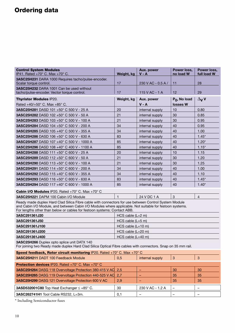
Ordering data
Control System Modules Aux. power Power loss, Power loss, IP41. Rated +70° C. Max +70° C. Weight, kg V - A no load W full load W
3ASC25H231 DARA 1000 Requires tacho/pulse-encoder.Scalar torque control. 17 230 V AC - 0.5 A / 11 28
3ASC25H232 DARA 1001 Can be used without tacho/pulse-encoder. Vector torque control. 17 115 V AC - 1 A 12 29
Thyristor Modules IP20. Weight, kg Aux. power P0, No load ∆V V
Rated +40/+50° C. Max +85° C. V - A losses W
3ASC25H281 DASD 101 +50° C 500 V - 25 A 20 internal supply 10 0.80
3ASC25H282 DASD 102 +50° C 500 V - 50 A 21 internal supply 30 0.85
3ASC25H283 DASD 103 +50° C 500 V - 100 A 21 internal supply 30 0.95
3ASC25H284 DASD 104 +50° C 500 V - 200 A 34 internal supply 40 0.95
3ASC25H285 DASD 105 +40° C 500 V - 355 A 34 internal supply 40 1.00
3ASC25H286 DASD 106 +50° C 500 V - 630 A 83 internal supply 40 1.45*
3ASC25H287 DASD 107 +40° C 500 V - 1000 A 85 internal supply 40 1.20*
3ASC25H296 DASD 108 +40° C 400 V - 1100 A 85 internal supply 40 1.15*
3ASC25H288 DASD 111 +50° C 600 V - 25 A 20 internal supply 10 1.15
3ASC25H289 DASD 112 +50° C 600 V - 50 A 21 internal supply 30 1.20
3ASC25H290 DASD 113 +50° C 600 V - 100 A 21 internal supply 30 1.25
3ASC25H291 DASD 114 +50° C 600 V - 200 A 34 internal supply 40 1.00
3ASC25H292 DASD 115 +40° C 600 V - 355 A 34 internal supply 40 1.10
3ASC25H293 DASD 116 +50° C 600 V - 630 A 83 internal supply 40 1.45*
3ASC25H294 DASD 117 +40° C 600 V - 1000 A 85 internal supply 40 1.40*
Cabin I/O Modules IP20. Rated +70° C. Max +70° C
3ASC25H221 DAPM 100 Cabin I/O Module 1 24 V DC 1 A 3 4
Ready made duplex Hard Clad Silica Fibre cable with connectors for use between Control System Module and Cabin I/O Module, and between Cabin I/O Modules where applicable. Not suitable for festoon systems. For lengths other than below or cables for festoon systems: Contact ABB.
3ASC291361J20 HCS cable (L=2 m)
3ASC291361J50 HCS cable (L=5 m)
3ASC291361J100 HCS cable (L=10 m)
3ASC291361J200 HCS cable (L=20 m)
3ASC291361J400 HCS cable (L=40 m)
3ASC25H266 Duplex opto splice unit DATX 140For joining two Ready made duplex Hard Clad Silica Optical Fibre cables with connectors. Snap on 35 mm rail.
Speed feedback, Rotor circuit monitoring IP20. Rated +70° C. Max +70° C
3ASC25H211 DADT 100 Feedback Module 0,5 internal supply 3 3
Protection devices IP20. Rated +70° C. Max +70° C
3ASC25H264 DASG 118 Overvoltage Protection 380-415 V AC 2,5 – 30 30
3ASC25H265 DASG 119 Overvoltage Protection 440-525 V AC 2,7 – 35 35
3ASC25H299 DASG 121 Overvoltage Protection 600 V AC 2,9 – 35 35
3ASD532001C80 Top Heat Exchanger ≤ +85° C. 30 230 V AC - 1.2 A – –
3ASC262741H1 Tool Cable RS232, L=3m. 0,1 – – –
* Including Semiconductor fuses
315
110
150
55
30
Internal panel wiring outlet(right side)
Free space bottom: Given by cables
Free space top: Not needed
3707,5 8,
5
422
405
8,5
473d=7
M6d=7
Keyholes for M6 (1/4") (2x)
-X1 -X2 -X3 -X4 -X5 -X6 -X7 -X8
11
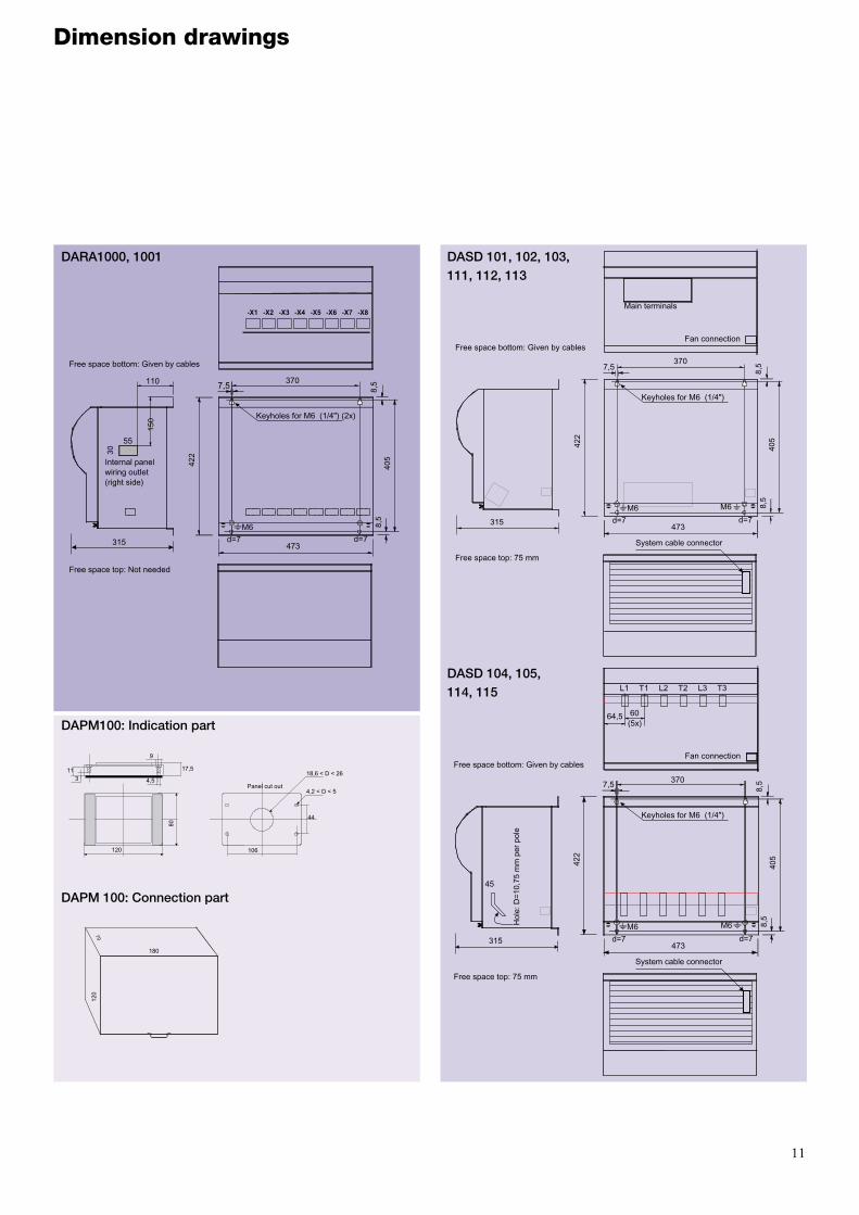
Dimension drawings
DARA1000, 1001 DASD 101, 102, 103, 111, 112, 113
DAPM100: Indication part
DASD 104, 105, 114, 115
DAPM 100: Connection part
120
80
4,5
113
17,5
9
Panel cut out
106
44
18,6 < D < 26
4,2 < D < 5
180
70
120
315
Free space bottom: Given by cables
Free space top: 75 mm
3707,5
8,5
422
405
8,5
473d=7
M6d=7
Keyholes for M6 (1/4")
M6
System cable connector
Fan connection
L1 T1 L2 T2 L3 T3
64,5 60(5x)
45
Hol
e: D
=10,
75 m
m p
er p
ole
315
Free space bottom: Given by cables
Free space top: 75 mm
7,5
8,5
422
405
8,5
473d=7
M6d=7
Keyholes for M6 (1/4")
M6
System cable connector
Fan connection
Main terminals
370

12
DASD 106, 107, 108, 116, 117 DADT 100, Feedback Module.
DASG 118, 119, 121Overvoltage protection Module.
d=7

Cabin I/O Module DAPM 100• Protection: IP 20• Calculated loss contribution: 3 W• Temperature range: Max +70° C.• Select one per operation station for every motion. Maximum two units; one for
the onboard operation station of the crane and the second for the relay unit of a radio remote controller.
Overvoltage Protection Modules DASG
• Protection: IP 20• Calculated loss contribution: 50 W• Temperature range: Max +70° C.• Prevents spikes and checks supply voltage level and phase sequence.• Select one DASG per crane or other machine.
Heat exchanger
• Protection: IP 55• Temperature range: Max +70 ambient /85° C inside the cubicle.• Selection guide for Thyristor Module:
- The ambient temperature is Tamb °C. - The required (mechanical) current is I1 A. - Required ASTAT controller current
Ie ≥ A, where TDR =
- 50 for Thyristor Modules rated ≤ 200 A and 630 A, - 40 for Thyristor Modules rated 355 A, 1000 A and 1100 A.
• Ie should never be less than I1.• Select the right number of heat exchangers 3ASD532001C80 as
a function of I1 and the c d f stated in the table:
13
Component selection
Control System Modules DARA 1000 and DARA 1001• Protection: IP 41• Calculated loss contribution: 20 W• Temperature range: Max +70° C.• Select 1 per motion.• DARA 1001 is selected for rotor frequency based
speed feedback or when precise torque control is required.
• DARA 1000 should be selected for tachometer feedback without rotor monitoring. Torque control is still better than traditional solutions.
Thyristor Modules DASD• Protection: IP 20• The nominal current capacity is valid for any duty
factor, ED [%], for the motor (15, 25, 40, 60 or 100 %).
• Calculated loss contribution: Ploss= P0+ 1.25 * ED[%] * 3 * I1 * ∆V [W], where 1.25 is a start current factor, I1 is the normal mechanical load current, P0 and ∆V are from the table.
• Temperature range: Nominal values are given at +40 or +50° C. Max +85° C. Reduce the allowed current by 1.2 %/K above +40 or +50° C. Highest altitude without derating is 1000 m.a.s.l.
• Normally select 1 per motion, but 2 units can be used in parallel without any current reduction.
Rotor Adoption Module DADT 100• Protection: IP 41• Calculated loss contribution: 3 W• Temperature range: Max +70° C.• Connect the rotor voltage to the DADT 100 module.
It is mounted in the vicinity of the Control System Module. DADT 100 has a 1.0 m long cable attached to connect to the DARA 1001.
• Select 1 DADT 100 per motion for tachometer freefeedback.
• Optionally, select 1 DADT 100 per motion for independent monitoring of tachometer speed feed-back and rotor condition.
• 2 or 4 DADT 100s are also chosen for rescue service with 1 of 2 or 2 of 4 motors in a motion, and the speed feedback can be selected from differentmotors in the configurations.
• Cubicle height with heat exchanger: best selection 1800 mm + 400 mm for the heat exchanger.
• Cubicle height without heat exchanger: best selection 1800 mm.• Cubicle width with or without one heat exchanger: best selection 800,
1000 or 1200 mm.• Cubicle width with two heat exchanger: best selection 1200 mm.• Cubicle width with three heat exchanger: best selection 1800 mm.• Instructions for mounting: Each cubicle separately enclosed with 200 mm
clear between cubicles, or all cubicles mounted together with free air circulation between the cubicles.
* 1100 A and 2200 A when DASD 108 is used.
100 * I1100 - (Tamb + 10 -TDR) * 1,2
Load current Duty factorI1 [A] c d f ( 40 %) c d f ( 60 %)0 - 100 0 0101 -200 0 1201 - 350 1 1351 - 500 1 2501 - 750 2 2751 - 1000* 2 31001 - 1200 3 31201 - 2000* 3 3Incomer cubicle Select one Heat exchanger less than is selectedfor the crane. for the Main hoist of the same crane.

ABB Automation Systems ABCrane Systems SE-721 67 Västerås, SwedenTelephone +46 21 34 00 00Fax +46 21 34 02 90Internet: www.abb.com/automation
ABB supplies a wide range of products for cranecontrol, having a wide experience of all types of craneoperation. ABB provides competitive and effectivesolutions to crane drive and control requirements.
ABB, with 200,000 employees serving cus-tomers in more than 100 countries, is a pioneer inthe development of technology and solutions formetals producers and processors.
From high-quality power transmission and dis-tribution systems to integrated drives and controlsystems; from process automation packages with instrumentation equipment to materials handlingwith cranes; from environmental products and systems,to installation, commissioning and training services.In Metals, you don’t have to look far. You’ll find theright electrical partner in ABB.
3AS
T000
473R
0001
CA
RE
OF.
Prin
ted
in S
wed
en b
y W
este
rås
Med
ia T
ryck
, Väs
terå
s 20
00.