ASSESSMENT OF VELUX DAYLIGHT VISUALIZER 2 AGAINST CIE …/media/com/daylightvisualizercie... · 5...
72
1 Ecole Nationale Des Travaux Publics de l’Etat Direction de la Recherche Département Génie Civil et Bâtiment URA 1652 Laboratoire des Sciences de l’Habitat Courriel : [email protected] Rue Maurice Audin 69518 Vaulx-en-Velin Cedex Téléphone : +33 (0)4 70 04 77 20 Télécopie : + 33 (0)4 70 04 70 41 HTTP://WWW.ENTPE.FR ASSESSMENT OF VELUX DAYLIGHT VISUALIZER 2 AGAINST CIE 171:2006 TEST CASES TEST CASES TO ASSESS THE ACCURACY OF LIGHTING COMPUTER PROGRAMS Test Cases 5.4 – 5.5 – 5.6 – 5.7 – 5.9 5.10 – 5.11 – 5.12 – 5.13 – 5.14
Transcript of ASSESSMENT OF VELUX DAYLIGHT VISUALIZER 2 AGAINST CIE …/media/com/daylightvisualizercie... · 5...

1
Ecole Nationale
Des Travaux Publics de l’Etat
Direction de la Recherche
Département Génie Civil et Bâtiment
URA 1652
Laboratoire des Sciences de l’Habitat
Courriel : [email protected]
Rue Maurice Audin
69518 Vaulx-en-Velin Cedex
Téléphone : +33 (0)4 70 04 77 20
Télécopie : + 33 (0)4 70 04 70 41
HTTP://WWW.ENTPE.FR
ASSESSMENT OF
VELUX DAYLIGHT VISUALIZER 2
AGAINST CIE 171:2006 TEST CASES
TEST CASES TO ASSESS THE
ACCURACY OF LIGHTING COMPUTER PROGRAMS
Test Cases
5.4 – 5.5 – 5.6 – 5.7 – 5.9
5.10 – 5.11 – 5.12 – 5.13 – 5.14

Assessment of VELUX Daylight Visualizer 2 Against CIE 171:2006 Test Cases Test Cases 5.4 – 5.5 – 5.6 – 5.7 – 5.9 – 5.10 – 5.11 – 5.12 – 5.13 – 5.14. February 6, 2009.
2
The following members of the ENTPE – DGCB / CNRS laboratory took part in the preparation and/or the examination of this report.
R. Labayrade Ph. D. Chief of project - Researcher
M. Fontoynont Ph. D. Research Director
C. Mouret Research Engineer
P. Avouac Research Engineer
MC. Jean Secretary

3
Contents
Abstract.....................................................................................................................4
Definitions.................................................................................................................5
Detailed results of the assessment of VELUX Daylight Visualizer 2 against CIE 171:2006 5.4 – 5.5 – 5.6 – 5.7 – 5.9 – 5.10 – 5.11 – 5.12 – 5.13 – 5.14 test cases .6
5.4 Luminous flux conservation...........................................................................................................6 5.5 Directional transmittance of clear glass τ ..................................................................................11 5.6 Light reflection over diffuse surfaces ..........................................................................................13 5.7 Diffuse reflection with internal obstructions...............................................................................20 5.9 Sky component for a roof unglazed opening and the CIE general sky types...............................23 5.10 Sky component under a roof glazed opening.............................................................................33 5.11 Sky component and external reflected component for a facade unglazed opening...................40 5.12 SC+ERC for a facade glazed opening ......................................................................................50 5.13 SC+ERC for an unglazed facade opening with a continuous external horizontal mask...........57 5.14 SC+ERC for an unglazed facade opening with a continuous external vertical mask...............60
Proposition of alternative analytical investigation and analytical reference for Test Cases 5.13 and 5.14 .......................................................................................63
Analytical Investigation of CIE Test Case 5.14.................................................................................63 Analytical Investigation of CIE Test Case 5.13.................................................................................65
Assessment overview of VELUX Daylight Visualizer 2 against CIE 171:2006 5.4 – 5.5 – 5.6 – 5.7 – 5.9 – 5.10 – 5.11 – 5.12 – 5.13 – 5.14 test cases .....................66
Assessment overview of VELUX Daylight Visualizer 2 for custom settings......................................67 Mapping between VELUX Daylight Visualizer 2 internal settings and VELUX Daylight Visualizer 2 global rendering quality slider.......................................................................................................68 Assessment overview of VELUX Daylight Visualizer 2 for all settings.............................................70
Conclusion about the assessment of VELUX Daylight Visualizer 2 against CIE 171:2006 test cases.........................................................................................71
Bibliographical references ....................................................................................72

Assessment of VELUX Daylight Visualizer 2 Against CIE 171:2006 Test Cases Test Cases 5.4 – 5.5 – 5.6 – 5.7 – 5.9 – 5.10 – 5.11 – 5.12 – 5.13 – 5.14. February 6, 2009.
4
ASSESSMENT OF VELUX DAYLIGHT VISUALIZER 2 AGAINST CIE 171:2006 TEST CASES
Abstract
VELUX Daylight Visualizer 2 is a software tool dedicated to daylighting design and analysis. It simulates daylight transport in buildings to aid professionals by predicting and documenting daylight levels and appearance of a space prior to realization of the building design. The software permit generation of 3D models in which roof and facade windows are freely inserted. Other settings include the location and orientation of the models, the date and time of the simulation, as well as the sky type (from clear to overcast). In addition to photorealistic rendering, the simulation output includes luminance, illuminance and daylight factor maps.
Like any light transport software, the critical question is whether VELUX Daylight Visualizer 2 produces trustable simulations the user can be confident in. A key point to answer this question is to assess the software capability to simulate the light transport in a physically correct way.
VELUX Daylight Visualizer 2 uses Dali - Luxion light transport algorithms.
The objective of this report is to present the results of the assessment of VELUX Daylight Visualizer 2 against test cases 5.4 – 5.5 – 5.6 – 5.7 – 5.9 – 5.10 – 5.11 – 5.12 – 5.13 – 5.14 (Test Cases to Assess the Accuracy of Lightning Computer Program). The test methodology is based on the comparison of simulation results to analytical reference, for different aspects of the light propagation. The selected test cases correspond to all the situations of CIE 171:2006 validation process where natural lighting is involved. The original CIE document the current study is based on is [CIE, 2006].
Internally, various light transport algorithms are involved in VELUX Daylight Visualizer 2. The settings of each algorithm impact on the simulation accuracy and rendering time. This report presents the results obtained for a particular set of settings (denoted by custom) that is detailed. Test cases are presented first, and then test results are given. Tables are given for analytical reference, simulation results and differences (in %) between the simulation results and the analytical reference. The average difference is also indicated. It is also indicated whether the test is passed, based on the ENTPE – DGCB / CNRS expertise in lighting design.
The sections in this report are numbered according to the test case numbers in the original CIE 171:2006 document.
An overview table is also presented at the end of this report, for all the test cases, all the test cases variants, and all the rendering qualities tested.

5
Definitions
Test case: A given building design scenario associated with reference data, to be used for assessing a given aspect of a lighting simulation.
Reference data: A set of values (calculated or measured) to be used as a reference when assessing the results of a simulation.
Analytical test case: A theoretical building design scenario wherein the reference data can be analytically calculated based on given assumptions (e.g. light source and surface photometry) and physical laws.

Assessment of VELUX Daylight Visualizer 2 Against CIE 171:2006 Test Cases Test Cases 5.4 – 5.5 – 5.6 – 5.7 – 5.9 – 5.10 – 5.11 – 5.12 – 5.13 – 5.14. February 6, 2009.
6
Detailed results of the assessment of VELUX Daylight Visualizer 2 against CIE 171:2006 5.4 – 5.5 – 5.6 – 5.7 – 5.9 – 5.10 – 5.11 – 5.12 – 5.13 – 5.14 test cases
Each section is dedicated to a test case. In each section, the test case is described, and the results of the assessment of VELUX Daylight Visualizer 2 against this test case are given, for a particular set of settings (denoted by custom) that is detailed.
Tables are given for analytical reference, simulation results and differences (in %) between the simulation results and the analytical reference. The average difference is also indicated. It is also indicated whether the test is passed, based on the ENTPE – DGCB / CNRS expertise in lighting design. The test cases have been simulated using a bi-Xeon 2.4 GHz computer running Windows XP-64 bits.
5.4 Luminous flux conservation
The objective of this test is to assess the luminous flux conservation between the light source and the internal surfaces of a space. An error in this conservation is equivalent to source of error in the calculated illuminance in a given scenario.
For daylighting simulations, the flux conservation should be verified between the incident luminous flux (in lumens) at an opening surface and the total direct flux reaching the different internal surfaces.
For artificial lighting scenarios, this flux conservation should be assessed between the output flux of a luminaire and the total direct flux reaching the different internal surfaces.
5.4.1 Analytical reference
5.4.1.1 Daylighting scenarios
In theory, in the case of a room with one opening (unglazed) and with black internal surfaces of 0% reflectance, the total direct luminous flux reaching the interior different surfaces φi, should be equal to the flux arriving at the opening surface φo:
φi = φo (1)
where:
φo = incident flux = Eo.So (lm)
Eo = average illuminance at the opening surface (lx)
So = area of the opening surface
φI = total direct flux transmitted by the aperture = Fn = En × Sn,
φn = luminous flux reaching the internal surface n (lm)
En = average illuminance of the surface n (lx)
Sn = area of the surface n (m²)
5.4.1.1 Artificial lighting scenarios
For an artificial lighting scenario, Fi is equal to the output flux associated with the luminaire.

7
5.4.2 Test case description
5.4.2.1 Daylighting scenarios
The luminous flux arriving at an opening surface depends on the sky model used by the program to be tested and can vary from one program to another. However, the flux conservation remains valid.
We have defined a sequence of geometries that can be used to verify whether this conservation is achieved for roof openings and for wall openings, and if it is affected by the size of the openings.
The geometry is a square room of dimensions 4m x 4m x 3m, with either a roof or a side opening at the centre of the roof or the wall. The roof opening sizes are 1m x 1m, 2m x 2m, 3m x 3m or 4m x 4m (full opening) with a thickness of 200 mm. The wall opening sizes are 2m x 1m, 3m x 2m or 4m x 3m (full opening) with a thickness of 200 mm.
The lighting simulation should be carried out with black interior surfaces (0% reflectance) to avoid the inter-reflection errors, and with no exterior ground reflections in the case of wall openings (0% external ground reflectance).
If the program being tested does not allow the direct lighting to be considered separately, knowing that some lighting programs attribute finite positive or negative additional values (called epsilon, or ε) to extreme reflectance values (close to 0% or to 100%), a possible source of error due to ε attributed to the 0% reflectance of black surfaces should be taken into consideration. The average error due to ε is equal to the related average indirect illuminance, is given by the following relation:
TSEr 0
1φ
εε
ε ×−
= (2)
where:
ST = room total internal surface area
Whatever sky condition is used, the resulting horizontal or vertical illuminance (on the roof surface or on an exterior wall surface) should be calculated and verified to be uniform in order to multiply this illuminance by the opening surface area to get the total flux φo incident at the opening surface (where φo = Eo × So)
The average illuminance for the different interior surfaces, including the opening thickness, should then be measured to calculate the total flux φi that entered the room (where φi = En × Sn) .
5.4.2.2 Artificial lighting scenarios
The test case described for the flux conservation in daylighting scenarios can be applied to artificial lighting scenarios by using a closed room (no opening) and any type of luminaire.
5.4.3 Analytical solution
In theory, φi / φo should be equal to 1. If RS = φi / φo for the simulation results, the relation 100 × ( RS –1) can be used to calculate the error in percentage due to the reduction or increase in the transmitted flux.

Assessment of VELUX Daylight Visualizer 2 Against CIE 171:2006 Test Cases Test Cases 5.4 – 5.5 – 5.6 – 5.7 – 5.9 – 5.10 – 5.11 – 5.12 – 5.13 – 5.14. February 6, 2009.
8
5.4.4 Assessment results
5.4.4.1 Test case 5.4 assessment results for a roof opening of 1 m x 1 m
Test case 5.4 Rendering quality Visualizer 2 slider not used
(custom) ambient on
trace level 8
ambient trace level 8
ambient precision 1
ambient complexity 10
ambient feature size 1
Φi / Φo for a roof opening of 1 m x 1 m
Opening type / Luminaire type
Φi / Φo Analytical Rs = Φi / Φo Simulation error (%)
100(Rs - 1)
Roof 1 m x 1 m 1 0.993 -0.747
Average difference (%) 0.747
Test status Passed
5.4.4.2 Test case 5.4 assessment results for a roof opening of 2 m x 2 m
Test case 5.4 Rendering quality Visualizer 2 slider not used
(custom) ambient on
trace level 8
ambient trace level 8
ambient precision 1
ambient complexity 10
ambient feature size 1
Φi / Φo for a roof opening of 2 m x 2 m
Opening type / Luminaire type
Φi / Φo Analytical Rs = Φi / Φo Simulation error (%)
100(Rs - 1)
Roof 2 m x 2 m 1 1.000 -0.041
Average difference (%) 0.041
Test status Passed

9
5.4.4.3 Test case 5.4 assessment results for a roof opening of 4 m x 4 m
Test case 5.4 Rendering quality Visualizer 2 slider not used
(custom) ambient on
trace level 8
ambient trace level 8
ambient precision 1
ambient complexity 10
ambient feature size 1
Φi / Φo for a roof opening of 4 m x 4 m
Opening type / Luminaire type
Φi / Φo Analytical Rs = Φi / Φo Simulation error (%)
100(Rs - 1)
Roof 4 m x 4 m 1 1.002 0.178
Average difference (%) 0.178
Test status Passed
5.4.4.4 Test case 5.4 assessment results for a wall opening of 2 m x 1 m
Test case 5.4 Rendering quality Visualizer 2 slider not used
(custom) ambient on
trace level 8
ambient trace level 8
ambient precision 1
ambient complexity 10
ambient feature size 1
Φi / Φo for a wall opening of 2 m x 1 m
Opening type / Luminaire type
Φi / Φo Analytical Rs = Φi / Φo Simulation error (%)
100(Rs - 1)
Wall 2 m x 1 m 1 1.004 0.410
Average difference (%) 0.410
Test status Passed

Assessment of VELUX Daylight Visualizer 2 Against CIE 171:2006 Test Cases Test Cases 5.4 – 5.5 – 5.6 – 5.7 – 5.9 – 5.10 – 5.11 – 5.12 – 5.13 – 5.14. February 6, 2009.
10
5.4.4.5 Test case 5.4 assessment results for a wall opening of 3 m x 2 m
Test case 5.4 Rendering quality Visualizer 2 slider not used
ambient on
trace level 8
ambient trace level 8
ambient precision 1
ambient complexity 10
ambient feature size 1
Φi / Φo for a wall opening of 3 m x 2 m
Opening type / Luminaire type
Φi / Φo Analytical Rs = Φi / Φo Simulation
error (%) 100(Rs - 1)
Wall 3 m x 2 m 1 0.995 -0.485
Average difference (%) 0.485
Test status Passed
5.4.4.6 Test case 5.4 assessment results for a wall opening of 4 m x 3 m
Test case 5.4 Rendering quality Visualizer 2 slider not used
(custom) ambient on
trace level 8
ambient trace level 8
ambient precision 1
ambient complexity 10
ambient feature size 1
Φi / Φo for a wall opening of 4 m x 3 m
Opening type / Luminaire type
Φi / Φo Analytical Rs = Φi / Φo Simulation
error (%) 100(Rs - 1)
Wall 4 m x 3 m 1 1.004 0.364
Average difference (%) 0.364
Test status Passed

11
5.5 Directional transmittance of clear glass τ
The objective of this test case is to assess the capability of a lighting program to take this directional transmittance into consideration. The importance of this test is related to the influence that a glazing material can have on the luminous flux transfer in a daylighting scenario.
The light transmission through glass materials varies with the angle of incidence at which light arrives at the glass surface. This directional transmittance affects the resulting illuminance distribution inside a building. For instance, it significantly reduces illuminance next to a window, or far to the side of a horizontal roof aperture.
5.5.1 Analytical reference
The directional transmittance of a glass at a given incidence angle can be calculated based on the Fresnel's equations.
Nevertheless, there exist in the literature a number of empirical and analytical references that have been proposed to simplify the description of the directional transmittance of different glass types.
Although these references do not differ considerably from each other, it is more convenient to assess a lighting program by comparing its results to the equation it is supposed to use for each type of glass.
For this test case, and as an example, we use an analytical equation proposed by Shlick for a clear glass [Shlick, 1993]. This equation does not take the absorption (due to the composition and the thickness of the glass) into consideration.
))cos-)(1R-(1(R-1 500 θτθ +≈ (3)
where:
θ = incidence angle
τθ = directional transmittance for the incidence angle θ
R0 = reflectance at normal incidence (0.04 for clear glass)
5.5.2 Test case description
The geometry used for this test is a square room of dimensions 4m x 4m x 3m, with a roof opening of 1m x 1m at the center of the roof and with a thickness of 200 mm. At the top of the opening is positioned a perfectly smooth glass material. The interior surfaces have a reflectance of 0%.
A sequence of simulations are to be carried out with an incoming directional parallel light beam aimed at the opening surface center with an incidence angle (θ) varying from 0 to 90° in 10° steps. For each position of the source, the total direct flux inside the room (φi = En × Sn) will be calculated with and without the glass surface.
The directional transmission τθ is equal to the total direct luminous flux obtained with the glass material at the opening surface divided by the total direct flux obtained without glass for the incidence angle θ, and it should follow the analytical solutions presented in Table 1.

Assessment of VELUX Daylight Visualizer 2 Against CIE 171:2006 Test Cases Test Cases 5.4 – 5.5 – 5.6 – 5.7 – 5.9 – 5.10 – 5.11 – 5.12 – 5.13 – 5.14. February 6, 2009.
12
5.5.3 Analytical solution
For the above mentioned analytical equation, the relation between the directional transmittance τθ of a clear glass at a given incidence angle θ and the normal transmittance τ0
is given by the following table. (N.B. τθ does not take the glass absorption into consideration, and τθ/τ0 represents the relative directional transmission.)
θ° 0 10 20 30 40 50 60 70 80 90
τθ 0.96 0.96 0.96 0.96 0.96 0.95 0.93 0.84 0.59 0.00
τθ/τ0 1.00 1.00 1.00 1.00 1.00 0.99 0.96 0.87 0.61 0.00
Table 1: Clear glass transmittance variation as a function of the incidence angle
5.5.4 Assessment results
Test case 5.5 Rendering quality Visualizer 2 slider not used
(custom) ambient on
trace level 8
ambient trace level 8
ambient precision 1
ambient complexity 10
ambient feature size 1
Directional transmittance of clear glass
Reference values
θ 0 10 20 30 40 50 60 70 80 90
τθ 0.96 0.96 0.96 0.96 0.96 0.95 0.93 0.84 0.59 0.00
τθ/τ0 1.00 1.00 1.00 1.00 1.00 0.99 0.96 0.87 0.61 0.00
Measured values
θ 0 10 20 30 40 50 60 70 80 90
τθ 0.96 0.96 0.96 0.96 0.95 0.94 0.91 0.83 0.61 0.00
τθ/τ0 1.00 1.00 1.00 0.99 0.99 0.98 0.95 0.86 0.64 0.00
Differences values (%)
θ 0 10 20 30 40 50 60 70 80 90
τθ 0.04 0.02 -0.06 -0.15 -0.63 -0.80 -2.05 -1.31 3.77 0.00
τθ/τ0 -0.34 -0.36 -0.44 -0.53 -1.02 -1.22 -1.54 -1.12 4.15 0.00
Average difference τθ (%) 0.88 Average difference τθ/τ0 (%) 1.07
Test status Passed

13
5.6 Light reflection over diffuse surfaces
The objective of this test case is to assess the accuracy of a lighting program in computing the light reflection over diffuse surfaces. The importance of this test is related to the inter reflections of the light inside a room and also to the reflection of daylight on the external ground and masks.
The surfaces of a geometry are usually considered as ideal diffuse. Inter-reflections are therefore calculated by using radiosity methods that are based on configuration and form factor equations. The direct illuminance being calculated first, each illuminated surface is then considered as a diffuse light source redistributing reflected flux towards the other surfaces of the space.
5.6.1 Analytical reference
Analytically, the indirect illuminance received at an elementary surface dS1 from a perfectly diffuse reflecting surface S2 is given by the following relation:
E1 = M2 × F12 (4)
where:
E1 = indirect illuminance received at point 1 from the surface S2 (lx).
M2 = Luminous exitance of the diffuse surface (lm/m²).
F12 = form factor between the receiving elementary surface dS1 and the diffuse surface S2.
Because S2 is perfectly diffuse, we also have:
M2 = π × L2 (5)
For a first reflection, M2 depends on the uniform direct illuminance at the surface S2, so we also have:
M2 = E2 × ρS2 (6)
where:
E2 = direct illuminance received on S2 (lx).
ρS2 = surface reflectance of S2.
5.6.2 Test case description
The scenario used for this test case is composed of the following elements (see Figures 1, 2 and 3):
− A diffuse and spectrally neutral horizontal surface S2 representing the ground, that receives uniform direct illuminance due to sun light or a distant light source.
− A vertical receiving surface S1-v with 0% reflectance representing a wall. − A horizontal receiving surface S1-hz with 0% reflectance oriented towards the ground that
represents a ceiling adjacent to the wall. The receiving surfaces S1-v and S1-hz do not receive direct illuminance and do not reflect luminous flux, but they receive a portion of the luminous flux diffusely reflected from surface S2.
To be able to take into consideration the influence of the size of the diffuse surface S2, three different scenarios are proposed:

Assessment of VELUX Daylight Visualizer 2 Against CIE 171:2006 Test Cases Test Cases 5.4 – 5.5 – 5.6 – 5.7 – 5.9 – 5.10 – 5.11 – 5.12 – 5.13 – 5.14. February 6, 2009.
14
5.6.2.1 Surface S2 of 50cm × 50cm
The geometry of this scenario is shown in Figure 1 and has the following description:
− The surface S2 is centered under the ceiling with a dimension of 50cm × 50cm. It has a reflectance of 80%.
− The vertical receiving surface S1-v is positioned at 2m from the center of S2 and has a dimension of 4m wide and 3m high.
− The horizontal receiving surface S1-hz is positioned 3m above the ground, is oriented toward S2, is adjacent to S1-v, and has a dimension of 4m × 4m.
− The surfaces S1-v and S1-hz are protected from direct illumination and from possible light leakage artefacts (common to most existing radiosity and ray-tracing methods) by an external envelope.
− The primary light source is oriented with an incidence angle of 45° to avoid direct illuminance of S1-v, and to provide uniform horizontal illuminance Ehz over S2.
1.75m
4m
1.75m
S1-V4mx3m
S250cmx50cm
S1-Hz
3m
incident flux (45°)
Figure 1: Test case description for S2 of 50cm×50cm
5.6.2.2 Surface S2 of 4m × 4m
The geometry of this scenario is shown in Figure 2. It is described as follows:
4m
S1-V4mx2.5m
S24mx4m
S1-Hz
3m
0,5
incident flux (35°)
Figure 2: Test case description for S2 of 4mx4m
− The surface S2 has a dimension of 4m × 4m. It has a reflectance of 30%.

15
− The vertical receiving surface S1-v is positioned 50 cm above the ground (to avoid direct illuminance) and 2m from the centre of S2, and has a dimension of 4m wide and 2.5m high.
− The horizontal receiving surface S1-hz is positioned 3m above the ground, is oriented toward S2, is adjacent to S1-v, and has a dimension of 4m × 4m.
− The surfaces S1-v and S1-hz are protected from direct illumination and from possible light leakage by an external envelope.
− The primary light source is oriented with an incidence angle of 35° to avoid direct illuminance on S1-v, and to provide uniform horizontal illuminance Ehz over S2 (see Figure 2).
5.6.2.3 Surface S2 of 500m × 500m (external ground)
The geometry of this scenario is shown in Figure 3. It is described as follows:
4m
S1-V4mx3m
S2500mx500m
S1-Hz
4m
incident flux (45°)
Figure 3: Test case description for S2 of 500m×500m
− The surface S2 is 500m × 500m and has a reflectance of 30%. − The vertical receiving surface S1-v is positioned 4m above S2 with the median axis of both
surfaces in the same plane. It is 4m wide and 3m high. − The horizontal receiving surface S1-hz is positioned 3m above the ground, oriented toward
S2, adjacent to S1-v and is 4m × 4m. − The surfaces S1-v and S1-hz are protected from direct illumination and from possible light
leakage by an external envelope. − The primary light source is oriented with an incidence angle of 45° to provide uniform
horizontal illuminance Ehz over S2.
5.6.2.4 Parametric studies
This test case can be associated with a parametric sensitivity analysis to observe the influence of the source orientation, the horizontal illuminance E1 and the surface reflectance of S2 on the accuracy of the results.
5.6.3 Analytical solution
To enable comparison between the simulation results and the analytical reference independently from the illuminance value over S2 or from its surface reflectance, the reference values are presented in the form of E / (Ehz × ρ), which is equal to the configuration factor between the measurement point and S2.
The measurement points at S1-v and S1-hz are positioned as shown in Figure 4. The analitycal references are given in tables 2, 3 and 4.

Assessment of VELUX Daylight Visualizer 2 Against CIE 171:2006 Test Cases Test Cases 5.4 – 5.5 – 5.6 – 5.7 – 5.9 – 5.10 – 5.11 – 5.12 – 5.13 – 5.14. February 6, 2009.
16
K L M NG H I J
3m
4m
0.5 0.5 0.5 0.5
0.5
0.5
0.5
0.5
0.5
0.5 0.5 0.5
2m
0.2
5
0.25
0.25
2m
S1-V
S1-Hz
F
E
D
C
B
A
Figure 4: measurement point positions
5.6.3.1 Scenario 1 (S2: 50 × 50cm)
Points of measurement for S1-v
A B C D E F
E/(Ehz×ρ) (%) 0.246 0.580 0.644 0.556 0.433 0.325
Points of measurement for S1-hz
G H I J K L M N
E/(Ehz×ρ) (%) 0.491 0.639 0.778 0.864 0.864 0.778 0.639 0.491
Table 2: variation of E/(Ehz×ρ) for S2 of 50cm×50cm
5.6.3.2 Scenario 2 (S2: 4 × 4m)
Points of measurement for S1-v
A B C D E F
E/(Ehz×ρ) (%) - 35.901 27.992 21.639 16.716 12.967
Points of measurement for S1-hz
G H I J K L M N
E/(Ehz×ρ) (%) 26.80 30.94 33.98 35.57 35.57 33.98 30.94 26.80
Table 3: variation of E/(Ehz×ρ) for S2 of 4m×4m
5.6.3.3 Scenario 3 (S2: 500 × 500m)
Points of measurement for S1-v
A B C D E F
E/(Ehz×ρ) (%) 3.080 9.097 14.718 19.767 24.161 27.896
Points of measurement for S1-hz
G H I J K L M N
E/(Ehz×ρ) (%) 10.95 13.26 16.21 20.00 24.80 30.77 37.87 45.84
Table 4: variation of E/(Ehz×ρ) for S2 of 500m×500m

17
5.6.4 Assessment results
5.6.4.1 Test Case 5.6 assessment results for S2 of 50 cm x 50 cm
Test case 5.6 Rendering quality Visualizer slider not used
(custom) ambient on
trace level 8
ambient trace level 8
ambient precision 1
ambient complexity 10
ambient feature size 1
Variation of E/(Ehz·ρ) for S2 of 50 cm x 50 cm
Reference values
Reference for S1-hz
A B C D E F
E/(Ehz·ρ) (%) 0.246 0.58 0.644 0.556 0.433 0.325
Reference for S1-hz
G H I J K L M N
E/(Ehz·ρ) (%) 0.491 0.639 0.778 0.864 0.864 0.778 0.639 0.491
Measured values
Points of measurement for S1-hz
A B C D E F
E/(Ehz·ρ) (%) 0.172 0.575 0.644 0.560 0.435 0.33
Points of measurement for S1-hz
G H I J K L M N
E/(Ehz·ρ) (%) 0.492 0.640 0.821 0.821 0.852 0.781 0.637 0.492
Differences values (%)
Differences for S1-hz
A B C D E F
E/(Ehz·ρ) (%) -30.04 -0.88 0.00 0.80 0.45 0.42
Differences for S1-hz
G H I J K L M N
E/(Ehz·ρ) (%) 0.30 0.20 5.49 -5.01 -1.43 0.36 -0.32 0.16
Average difference (%) 3.28
Test status Passed

Assessment of VELUX Daylight Visualizer 2 Against CIE 171:2006 Test Cases Test Cases 5.4 – 5.5 – 5.6 – 5.7 – 5.9 – 5.10 – 5.11 – 5.12 – 5.13 – 5.14. February 6, 2009.
18
5.6.4.2 Test Case 5.6 assessment results for S2 of 4 m x 4 m
Test case 5.6 Rendering quality Visualizer slider not used
(custom) ambient on
trace level 8
ambient trace level 8
ambient precision 1
ambient complexity 10
ambient feature size 1
Variation of E/(Ehz·ρ) for S2 of 4 m x 4 m
Reference values
Reference for S1-hz
A B C D E F
E/(Ehz·ρ) (%) - 35.901 27.992 21.639 16.716 12.967
Reference for S1-hz
G H I J K L M N
E/(Ehz·ρ) (%) 26.8 30.94 33.98 35.57 35.57 33.987 30.94 26.8
Measured values
Points of measurement for S1-hz
A B C D E F
E/(Ehz·ρ) (%) 45.193 35.916 27.980 21.639 16.725 12.98
Points of measurement for S1-hz
G H I J K L M N
E/(Ehz·ρ) (%) 26.787 30.922 35.553 35.553 35.559 33.962 30.938 26.736
Differences values (%)
Difference for S1-hz
A B C D E F
E/(Ehz·ρ) (%) - 0.04 -0.04 0.00 0.05 0.10
Difference for S1-hz
G H I J K L M N
E/(Ehz·ρ) (%) -0.05 -0.06 4.63 -0.05 -0.03 -0.07 -0.01 -0.24
Average difference (%) 0.38
Test status Passed

19
5.6.4.3 Test Case 5.6 assessment results for S2 of 500 m x 500 m
Test case 5.6 Rendering Quality Visualizer slider not used
(custom) ambient on
trace level 8
ambient trace level 8
ambient precision 1
ambient complexity 10
ambient feature size 1
Variation of E/(Ehz·ρ) for S2 of 500 m x 500 m
Reference values
Reference for S1-hz
A B C D E F
E/(Ehz·ρ) (%) 3.08 9.097 14.718 19.767 24.161 27.896
Reference for S1-hz
G H I J K L M N
E/(Ehz·ρ) (%) 10.95 13.26 16.21 20 24.8 30.77 37.87 45.84
Measured values
Points of measurement for S1-hz
A B C D E F
E/(Ehz·ρ) (%) 3.047 9.124 14.778 19.846 24.215 27.99
Points of measurement for S1-hz
G H I J K L M N
E/(Ehz·ρ) (%) 10.981 13.287 20.035 20.035 24.851 30.850 37.949 45.980
Differences values (%)
Difference for S1-hz
A B C D E F
E/(Ehz·ρ) (%) -1.07 0.30 0.41 0.40 0.22 0.35
Difference for S1-hz
G H I J K L M N
E/(Ehz·ρ) (%) 0.28 0.20 23.59 0.17 0.21 0.26 0.21 0.30
Average difference (%) 2.00
Test status Passed

Assessment of VELUX Daylight Visualizer 2 Against CIE 171:2006 Test Cases Test Cases 5.4 – 5.5 – 5.6 – 5.7 – 5.9 – 5.10 – 5.11 – 5.12 – 5.13 – 5.14. February 6, 2009.
20
5.7 Diffuse reflection with internal obstructions
The objective of this test case is to verify the capability of a program to simulate the influence of an obstruction to diffuse reflection. The importance of this test is related to the shading influence of internal furniture or to the externally reflected component received from external objects through apertures.
The presence of obstructions presents a higher level of complexity compared to the simulation in “empty room” geometries. Additional errors are introduced that make the simulation results more sensitive to the calculation parameters (radiosity meshing, shadow calculation, et cetera).
5.7.1 Analytical reference
The analytical reference for indirect lighting calculation is the same as the one used for 5.6. However, for this test case, the dimension of the portion of S2 contributing to the indirect illuminance of a given point has to be calculated according to the position of this point.
5.7.2 Test case description
The scenario used for this test case is composed of the following elements (see Figure 5)
− A vertical diffuse and spectrally neutral surface S2 representing a wall receiving uniform direct illuminance Ev from sun light or distant light source.
− A vertical receiving surface S1-v with 0% reflectance representing a wall parallel to S2 − A horizontal receiving surface S1-hz with 0% reflectance adjacent to S1-v and representing
the ground − A vertical obstruction positioned between S1-hz and S2 that is parallel to both surfaces
The receiving surfaces S1-v and S1-hz do not receive direct illuminance and do not reflect luminous flux, but they receive a portion of the luminous flux diffused by a portion of S2.
The geometry is shown in Figure 5 and is described as follows:
1
2,5
4
1,3
S1-VS2
S1-Hz
3
incident flux (60°)
Figure 5: Description of test case with diffuse reflectance and obstruction
The surface S2 has a dimension of 4m × 3m and a surface reflectance of 60%.
The receiving vertical surface S1-v has a dimension of 4m × 3m and is positioned to face S2
at a 4m distance.
The receiving horizontal surface S1-hz is positioned at ground level, is adjacent to S1-v, and has a dimension of 2.50m × 4m.

21
The vertical obstruction is 4m wide and 1m high. It has a thickness of 20cm and is positioned at 2.50m from S1-v and 1.30m from S2.
The surfaces S1-v and S1-hz are protected from direct illumination and from possible light leakage by an external envelope (see Figure 5).
The primary light source is oriented with an incidence angle of 60° to provide uniform vertical illuminance Ev over S2.
5.7.3 Analytical solution
To enable comparison between the simulation results and the analytical reference independently from the illuminance value over S2 or from its surface reflectance, the reference values are presented under the form of E / (Ev × ρ) (see Table 5). This is equal to the configuration factor value between the measurement point and the unobstructed portion of S2. The measurement points at S1-v and S1-hz are positioned as shown in Figure 6.
The authors of the current study believe the analytical reference given in the original CIE document is erroneous for test case 5.7. The Chief of Project of CIE 171:2006 document (Fawaz Maamari) has been contacted and acknowledged the analytical reference for Test Case 5.7 is certainly erroneous, and explained the CIE will emit an errata. The errors in the analytical reference given by the CIE have been confirmed by another study: [Geisler-Modorer, 2008]. We use the reference given in this study, which includes an analytical demonstration.
F
E
D
C
A
B
GHIJK
S2S1-V
0.5
0.5
0.5
0.5
2m
2m
0.2
5
0.25
0.2
5
2.5
0.2 3m
0.5 0.5 0.5 0.5
0.5
S1-Hz
Figure 6: Points of measurement position for internal obstruction test case
Points of measurement for S1-v
A B C D E F
E/(Ev×ρ) (%) 16.07 16.33 15.39 13.32 10.31 7.07
Points of measurement for S1-hz
G H I J K
E/(Ev×ρ) (%) 3.38 3.62 3.01 0.00 0.00
Table 5: Variation of E/(Ev×ρ) for the test case of reflections with
internal obstruction

Assessment of VELUX Daylight Visualizer 2 Against CIE 171:2006 Test Cases Test Cases 5.4 – 5.5 – 5.6 – 5.7 – 5.9 – 5.10 – 5.11 – 5.12 – 5.13 – 5.14. February 6, 2009.
22
5.7.4. Test Case 5.7 assessment results
Test case 5.7 Rendering quality Visualizer slider not used (custom) ambiant on trace level 8 ambiant trace level 8 ambiant precision 1 ambiant complexity 10 ambiant feature size 1 Variation of E/(Ev·ρ) for the test case of reflections with internal obstruction
Reference values
Reference for S1-v
A B C D E F
E/(Ev·ρ) (%) 16.07 16.33 15.39 13.32 10.31 7.07
Reference for S1-hz
G H I J K
E/(Ev·ρ) (%) 3.38 3.62 3.01 0.00 0.00
Measured values
Points of measurement for S1-v
A B C D E F
E/(Ev·ρ) (%) 16.00 16.33 15.37 13.26 10.33 7.07
Points of measurement for S1-hz
G H I J K
E/(Ev·ρ) (%) 3.38 3.63 3.00 0.00 0.00
Differences values (%)
Difference for S1-v
A B C D E F
E/(Ev·ρ) (%) -0.42 0.00 -0.15 -0.44 0.13 -0.09
Difference for S1-hz
G H I J K
E/(Ev·ρ) (%) 0.04 0.15 -0.30 0.00 0.00
Average difference (%) 0.16
Test status Passed

23
5.9 Sky component for a roof unglazed opening and the CIE general sky types.
The proposed test case aims to test the capability of a lighting program to calculate the sky component under different sky conditions, in particular those standardized by the CIE general sky [CIE, 2003]. The importance of this test is related to the calculation of the daylight factor that is a commonly used parameter for determining daylight availability inside a building.
The daylight factor DF at a certain point P is subdivided as following:
DF (%) = SC + ERC + IRC = 100×hz
p
EE (7)
where:
SC = sky component
ERC = external reflected component
IRC = internal reflected component
Ep = illuminance at point P
Ehz = roof horizontal illuminance (with no obstructions)
In the scenarios tested, the wall thickness is not taken into consideration and no glazing material is used to avoid the related errors.
5.9.1 Analytical reference
The sky component of the daylight factor takes the direct illuminance received at the interior of the room through the aperture from the visible zone of the sky into consideration.
This illuminance varies for a given point according to the luminance distribution of the sky, and the portion of the sky that is visible to the point. This luminance distribution is usually proposed as a standardized sky model. For the CIE general sky types, the direct component can be calculated analytically for the type 16 (CIE overcast sky) and for the type 5 (uniform sky). The algorithms to be used for these two types are described below.
The proposed analytical solution for the other sky types were calculated with a computer program developed for this purpose (Skylux), and validated through comparison with the analytical solutions for types 5 and 16. The procedure used subdivides the surface into thousands of sub-surfaces and calculates the average luminance of the sky zone visible through each sub-surface from a given measurement point. The direct illuminance is then calculated by integrating the contribution of each sub-surface. The difference between the program results and the analytical solution (for CIE sky types 5 and 16) is less than 0.1%.
5.9.1.1 Sky component for CIE sky type 5 (uniform)
The sky component under a uniform sky can be calculated by using the configuration factors between the surface opening and the measurement point (SC = F12).
In the case of an opening parallel to the receiving surface (ground measurement points), the configuration factor F12 between the receiving elementary surface dS1 representing the measurement point and the surface opening S2 through which the uniform sky is visible, is given by Equation 6.
In the case of an opening perpendicular to the receiving surface (wall measurement points), the configuration factor F12 between the receiving elementary surface dS1 representing the measurement point and the opening surface S2 through which the uniform sky is visible, is given by Equation 7.

Assessment of VELUX Daylight Visualizer 2 Against CIE 171:2006 Test Cases Test Cases 5.4 – 5.5 – 5.6 – 5.7 – 5.9 – 5.10 – 5.11 – 5.12 – 5.13 – 5.14. February 6, 2009.
24
5.9.1.2 Sky component for CIE sky type 16 (overcast)
The sky component on a horizontal point directly below the corner of a rectangular unglazed opening under a CIE overcast sky is given by the equation [Tregenza, 1993]:
SC = ( ) ( ) ( )( )
( ) ( )( ) %100*]cossinarcsincoscosarcsin2sin2sinsin2sinsinsin5.1[
baz
dacbzzbcadz
ααπ+−
++++ (8)
where:
z = π71
α =
b
a
tantanarctan
and angles a, b and c are in radians as shown in Figure 7.
Figure 7: sky component calculation under CIE overcast sky (floor
point and horizontal opening)
5.9.2 Description of the test case
3m
4m
0.5 0.5 0.5 0.5
0.5
0.5
0.5
0.5
0.5
0.5 0.5 0.5
2m
2m
0.25 0.25
0.25
C
D
E
B
A
F
HG JI NMLK
Figure 8: geometry and measurement points description
The geometry used for this test case is a rectangular room of 4m × 4m × 3m, with a roof opening at the centre of the ceiling with a dimension of 1m × 1m or 4m × 4m. The thickness of the roof is not taken into consideration; however an external envelope is recommended to avoid possible light leakage. The internal surfaces are ideal diffuse reflectors with 0% reflectance.

25
The luminance distribution of the sky is obtained from the CIE general sky equations with the sun position defined on the South (face to the wall reference points) and at 60° elevation. The direct sun illuminance is not taken into consideration.
5.9.3 Analytical solution
The measurement points are positioned as shown in Figure 8. The reference values for this scenario are given in the following sections.
5.9.3.1 Opening of 1m × 1m
Figure 9 below shows a graphical presentation of the analytical reference for CIE sky types 1 (overcast), 9 and 12 (clear).
0.0
1.0
2.0
3.0
4.0
5.0
A B C D E F
FJD
(%
)-
CIE-T1 CIE-T9 CIE-T12
0.01.02.03.04.05.06.07.0
G H I J K L M N
FJD
(%
)
CIE-T1 CIE-T9 CIE-T12
Figure 9: sky component variation under CIE sky types 1, 9 and 12, for a roof unglazed opening of 1m×1m
5.9.3.2 Opening of 4m × 4m
Figure 10 below shows a graphical presentation of the analytical reference for CIE sky types 1, 9 and 12.
0.010.020.030.040.050.060.070.0
A B C D E F
FJD
(%
)-
CIE-T1 CIE-T9 CIE-T12
0.0
10.0
20.0
30.0
40.0
50.0
G H I J K L M N
FJD
(%
)
CIE-T1 CIE-T9 CIE-T12
Figure 10: sky component variation under CIE sky types 1, 9 and 12, for a roof unglazed opening of 4m×4m
SC
(%
)
SC
(%
)
SC
(%
)
SC
(%
)

Assessment of VELUX Daylight Visualizer 2 Against CIE 171:2006 Test Cases Test Cases 5.4 – 5.5 – 5.6 – 5.7 – 5.9 – 5.10 – 5.11 – 5.12 – 5.13 – 5.14. February 6, 2009.
26
5.9.4.1 Test Case 5.9 assessment results for a roof opening, size 1 m x 1 m, under CIE general sky types
Test case 5.9 Rendering quality Visualizer slider not used
(custom) ambient on
trace level 8
ambient trace level 8
ambient precision 1
ambient complexity 10
ambient feature size 1
SC on wall for a roof opening, under CIE general sky types

27
Reference values
SC on wall/Reference points
A B C D E F
CIE Type 1 0.46 1.64 2.34 2.26 1.88 1.47
CIE Type 2 0.40 1.72 2.86 3.15 2.90 2.44
CIE Type 3 1.36 1.78 2.22 2.46 2.05 0.79
CIE Type 4 0.71 2.17 3.06 3.15 2.79 2.30
CIE Type 5 1.04 2.39 2.59 2.20 1.70 1.27
CIE Type 6 0.94 2.58 3.27 3.16 2.71 2.19
CIE Type 7 0.82 2.52 3.61 3.91 3.69 3.19
CIE Type 8 0.72 2.43 3.86 4.56 4.60 4.18
CIE Type 9 1.64 3.53 3.67 3.14 2.49 1.91
CIE Type 10 1.46 3.52 4.13 3.96 3.45 2.84
CIE Type 11 1.30 3.46 4.49 4.69 4.39 3.79
CIE Type 12 1.74 3.76 4.55 4.61 4.24 3.63
CIE Type 13 1.61 3.76 4.87 5.16 4.89 4.26
CIE Type 14 2.22 4.01 4.88 5.05 4.72 4.08
CIE Type 15 2.14 4.16 5.23 5.47 5.11 4.41
SC on floor /Reference points
G H I J K L M N
CIE Type 1 2.33 3.11 3.84 4.29 3.84 4.29 3.11 2.33
CIE Type 2 4.00 5.00 5.47 5.37 4.73 3.76 2.76 1.90
CIE Type 3 2.13 2.80 3.42 3.81 3.81 3.42 2.80 2.13
CIE Type 4 3.72 4.58 4.97 4.85 4.27 3.42 2.53 1.77
CIE Type 5 1.95 2.52 3.04 3.37 3.37 3.04 2.52 1.95
CIE Type 6 3.47 4.20 4.49 4.36 3.84 3.09 2.31 1.65
CIE Type 7 5.21 5.96 5.70 4.93 3.92 2.90 2.04 1.39
CIE Type 8 6.94 7.65 6.78 5.38 3.93 2.71 1.80 1.17
CIE Type 9 2.88 3.34 3.45 3.29 2.89 2.37 1.83 1.37
CIE Type 10 4.42 4.85 4.49 3.80 3.02 2.27 1.65 1.18
CIE Type 11 6.01 6.36 5.45 4.23 3.09 2.16 1.48 1.01
CIE Type 12 5.72 6.01 5.12 3.97 2.90 2.03 1.40 0.96
CIE Type 13 6.76 7.01 5.80 4.30 2.98 1.99 1.30 0.86
CIE Type 14 6.43 6.64 5.47 4.05 2.81 1.87 1.23 0.82
CIE Type 15 6.94 7.19 5.93 4.36 2.96 1.90 1.20 0.76

Assessment of VELUX Daylight Visualizer 2 Against CIE 171:2006 Test Cases Test Cases 5.4 – 5.5 – 5.6 – 5.7 – 5.9 – 5.10 – 5.11 – 5.12 – 5.13 – 5.14. February 6, 2009.
28
Measured values
SC on wall/measurement points
A B C D E F
CIE Type 1 0.45 1.64 2.33 2.25 1.88 1.47
CIE Type 2 0.39 1.72 2.85 3.14 2.91 2.44
CIE Type 3 0.77 2.05 2.46 2.22 1.79 1.37
CIE Type 4 0.69 2.17 3.05 3.14 2.82 2.31
CIE Type 5 1.02 2.39 2.58 2.20 1.71 1.28
CIE Type 6 0.91 2.57 3.25 3.16 2.72 2.18
CIE Type 7 0.81 2.51 3.59 3.91 3.71 3.19
CIE Type 8 0.70 2.43 3.85 4.53 4.62 4.18
CIE Type 9 1.59 3.53 3.66 3.13 2.49 1.90
CIE Type 10 1.42 3.52 4.13 3.95 3.46 2.85
CIE Type 11 1.27 3.45 4.50 4.69 4.41 3.78
CIE Type 12 1.69 3.77 4.53 4.62 4.28 3.63
CIE Type 13 1.57 3.77 4.86 5.16 4.92 4.26
CIE Type 14 2.15 4.01 4.88 5.05 4.75 4.08
CIE Type 15 2.08 4.17 5.23 5.47 5.14 4.39
SC on floor /measurement points
G H I J K L M N
CIE Type 1 2.34 3.09 3.86 4.27 4.29 3.91 3.09 2.33
CIE Type 2 3.98 4.97 5.51 5.35 4.69 3.84 2.74 1.91
CIE Type 3 2.12 2.79 3.45 3.79 3.78 3.49 2.78 2.13
CIE Type 4 3.71 4.56 5.02 4.86 4.23 3.49 2.51 1.77
CIE Type 5 1.95 2.51 3.07 3.36 3.34 3.09 2.51 1.96
CIE Type 6 3.44 4.17 4.54 4.35 3.80 3.15 2.29 1.65
CIE Type 7 5.19 5.92 5.72 4.95 3.87 2.96 2.02 1.39
CIE Type 8 6.92 7.59 6.80 5.38 3.86 2.77 1.78 1.17
CIE Type 9 2.86 3.31 3.48 3.28 2.87 2.41 1.82 1.37
CIE Type 10 4.42 4.80 4.51 3.82 2.99 2.33 1.63 1.17
CIE Type 11 5.99 6.30 5.45 4.24 3.02 2.20 1.47 1.02
CIE Type 12 5.71 5.96 5.15 3.98 2.84 2.07 1.39 0.97
CIE Type 13 6.70 6.96 5.83 4.32 2.91 2.02 1.29 0.86
CIE Type 14 6.43 6.60 5.49 4.05 2.76 1.92 1.23 0.82
CIE Type 15 6.92 7.16 5.94 4.35 2.89 1.95 1.19 0.76
29
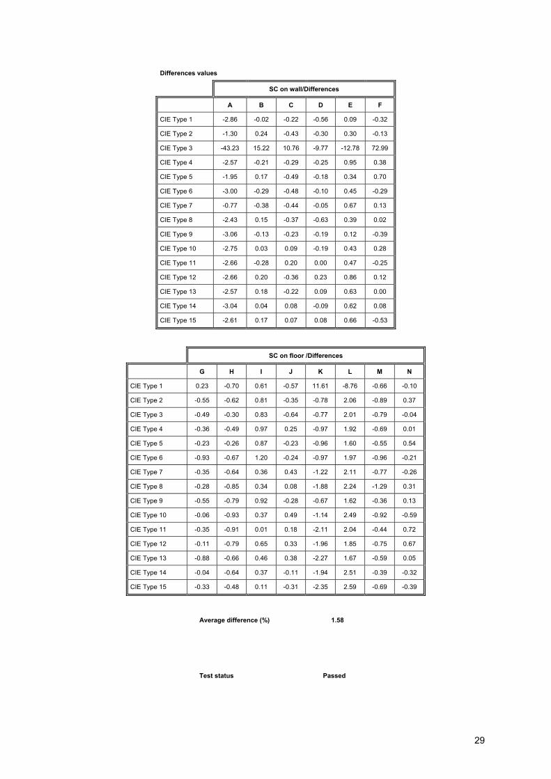
Differences values
SC on wall/Differences
A B C D E F
CIE Type 1 -2.86 -0.02 -0.22 -0.56 0.09 -0.32
CIE Type 2 -1.30 0.24 -0.43 -0.30 0.30 -0.13
CIE Type 3 -43.23 15.22 10.76 -9.77 -12.78 72.99
CIE Type 4 -2.57 -0.21 -0.29 -0.25 0.95 0.38
CIE Type 5 -1.95 0.17 -0.49 -0.18 0.34 0.70
CIE Type 6 -3.00 -0.29 -0.48 -0.10 0.45 -0.29
CIE Type 7 -0.77 -0.38 -0.44 -0.05 0.67 0.13
CIE Type 8 -2.43 0.15 -0.37 -0.63 0.39 0.02
CIE Type 9 -3.06 -0.13 -0.23 -0.19 0.12 -0.39
CIE Type 10 -2.75 0.03 0.09 -0.19 0.43 0.28
CIE Type 11 -2.66 -0.28 0.20 0.00 0.47 -0.25
CIE Type 12 -2.66 0.20 -0.36 0.23 0.86 0.12
CIE Type 13 -2.57 0.18 -0.22 0.09 0.63 0.00
CIE Type 14 -3.04 0.04 0.08 -0.09 0.62 0.08
CIE Type 15 -2.61 0.17 0.07 0.08 0.66 -0.53
SC on floor /Differences
G H I J K L M N
CIE Type 1 0.23 -0.70 0.61 -0.57 11.61 -8.76 -0.66 -0.10
CIE Type 2 -0.55 -0.62 0.81 -0.35 -0.78 2.06 -0.89 0.37
CIE Type 3 -0.49 -0.30 0.83 -0.64 -0.77 2.01 -0.79 -0.04
CIE Type 4 -0.36 -0.49 0.97 0.25 -0.97 1.92 -0.69 0.01
CIE Type 5 -0.23 -0.26 0.87 -0.23 -0.96 1.60 -0.55 0.54
CIE Type 6 -0.93 -0.67 1.20 -0.24 -0.97 1.97 -0.96 -0.21
CIE Type 7 -0.35 -0.64 0.36 0.43 -1.22 2.11 -0.77 -0.26
CIE Type 8 -0.28 -0.85 0.34 0.08 -1.88 2.24 -1.29 0.31
CIE Type 9 -0.55 -0.79 0.92 -0.28 -0.67 1.62 -0.36 0.13
CIE Type 10 -0.06 -0.93 0.37 0.49 -1.14 2.49 -0.92 -0.59
CIE Type 11 -0.35 -0.91 0.01 0.18 -2.11 2.04 -0.44 0.72
CIE Type 12 -0.11 -0.79 0.65 0.33 -1.96 1.85 -0.75 0.67
CIE Type 13 -0.88 -0.66 0.46 0.38 -2.27 1.67 -0.59 0.05
CIE Type 14 -0.04 -0.64 0.37 -0.11 -1.94 2.51 -0.39 -0.32
CIE Type 15 -0.33 -0.48 0.11 -0.31 -2.35 2.59 -0.69 -0.39
Average difference (%) 1.58
Test status Passed
Assessment of VELUX Daylight Visualizer 2 Against CIE 171:2006 Test Cases Test Cases 5.4 – 5.5 – 5.6 – 5.7 – 5.9 – 5.10 – 5.11 – 5.12 – 5.13 – 5.14. February 6, 2009.
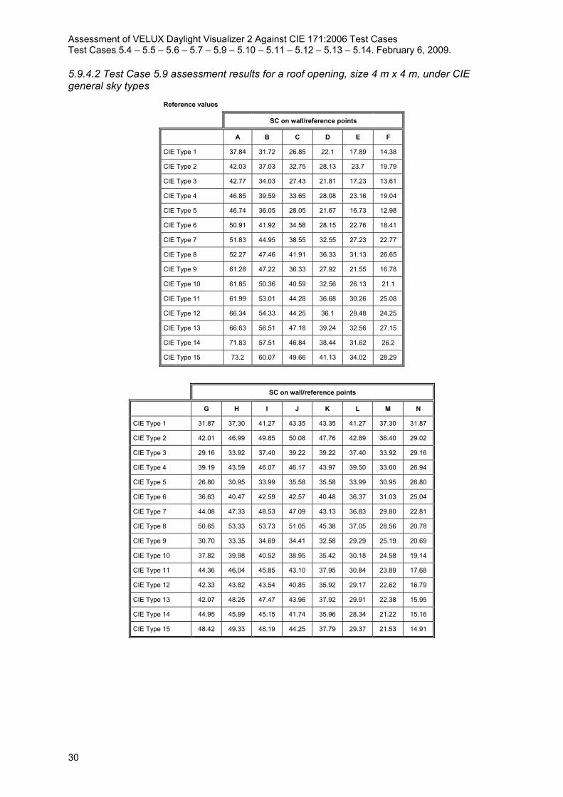
30
5.9.4.2 Test Case 5.9 assessment results for a roof opening, size 4 m x 4 m, under CIE general sky types
Reference values
SC on wall/reference points
A B C D E F
CIE Type 1 37.84 31.72 26.85 22.1 17.89 14.38
CIE Type 2 42.03 37.03 32.75 28.13 23.7 19.79
CIE Type 3 42.77 34.03 27.43 21.81 17.23 13.61
CIE Type 4 46.85 39.59 33.65 28.08 23.16 19.04
CIE Type 5 46.74 36.05 28.05 21.67 16.73 12.98
CIE Type 6 50.91 41.92 34.58 28.15 22.76 18.41
CIE Type 7 51.83 44.95 38.55 32.55 27.23 22.77
CIE Type 8 52.27 47.46 41.91 36.33 31.13 26.65
CIE Type 9 61.28 47.22 36.33 27.92 21.55 16.78
CIE Type 10 61.85 50.36 40.59 32.56 26.13 21.1
CIE Type 11 61.99 53.01 44.28 36.68 30.26 25.08
CIE Type 12 66.34 54.33 44.25 36.1 29.48 24.25
CIE Type 13 66.63 56.51 47.18 39.24 32.56 27.15
CIE Type 14 71.83 57.51 46.84 38.44 31.62 26.2
CIE Type 15 73.2 60.07 49.66 41.13 34.02 28.29
SC on wall/reference points
G H I J K L M N
CIE Type 1 31.87 37.30 41.27 43.35 43.35 41.27 37.30 31.87
CIE Type 2 42.01 46.99 49.85 50.08 47.76 42.89 36.40 29.02
CIE Type 3 29.16 33.92 37.40 39.22 39.22 37.40 33.92 29.16
CIE Type 4 39.19 43.59 46.07 46.17 43.97 39.50 33.60 26.94
CIE Type 5 26.80 30.95 33.99 35.58 35.58 33.99 30.95 26.80
CIE Type 6 36.63 40.47 42.59 42.57 40.48 36.37 31.03 25.04
CIE Type 7 44.08 47.33 48.53 47.09 43.13 36.83 29.80 22.81
CIE Type 8 50.65 53.33 53.73 51.05 45.38 37.05 28.56 20.78
CIE Type 9 30.70 33.35 34.69 34.41 32.58 29.29 25.19 20.69
CIE Type 10 37.82 39.98 40.52 38.95 35.42 30.18 24.58 19.14
CIE Type 11 44.36 46.04 45.85 43.10 37.95 30.84 23.89 17.68
CIE Type 12 42.33 43.82 43.54 40.85 35.92 29.17 22.62 16.79
CIE Type 13 42.07 48.25 47.47 43.96 37.92 29.91 22.38 15.95
CIE Type 14 44.95 45.99 45.15 41.74 35.96 28.34 21.22 15.16
CIE Type 15 48.42 49.33 48.19 44.25 37.79 29.37 21.53 14.91

31
Measured values
SC on wall/measurement points
A B C D E F
CIE Type 1 35.87 31.53 26.78 22.10 17.87 14.37
CIE Type 2 40.43 36.89 32.67 28.15 23.71 19.77
CIE Type 3 41.02 33.86 27.36 21.81 17.21 13.60
CIE Type 4 45.43 39.46 33.56 28.09 23.18 19.02
CIE Type 5 45.20 35.88 27.97 21.65 16.72 12.99
CIE Type 6 49.68 41.79 34.50 28.15 22.78 18.42
CIE Type 7 51.60 44.93 38.49 32.58 27.27 22.73
CIE Type 8 53.20 47.56 41.84 36.34 31.21 26.60
CIE Type 9 60.41 47.10 36.22 27.92 21.53 16.79
CIE Type 10 62.04 50.46 40.61 32.68 26.22 21.13
CIE Type 11 63.05 53.09 44.22 36.71 30.32 25.06
CIE Type 12 67.43 54.44 44.20 36.14 29.53 24.24
CIE Type 13 68.30 56.67 47.11 39.28 32.65 27.14
CIE Type 14 73.58 57.63 46.77 38.50 31.68 26.16
CIE Type 15 74.99 60.22 49.61 41.16 34.12 28.26
SC on wall/measurement points
G H I J K L M N
CIE Type 1 31.76 37.26 41.24 43.31 43.30 41.25 37.26 31.83
CIE Type 2 41.90 46.99 49.78 50.07 47.69 42.88 36.35 28.95
CIE Type 3 29.06 33.90 37.35 39.21 39.17 37.38 33.88 29.12
CIE Type 4 39.07 43.56 45.96 46.15 43.91 39.48 33.53 26.89
CIE Type 5 26.74 30.91 33.95 35.56 35.54 33.98 30.92 26.76
CIE Type 6 36.52 40.46 42.50 42.54 40.40 36.37 31.00 25.00
CIE Type 7 43.95 47.33 48.43 47.12 43.09 36.88 29.71 22.77
CIE Type 8 50.47 53.35 53.61 51.10 45.35 37.09 28.49 20.74
CIE Type 9 30.61 33.36 34.64 34.39 32.52 29.31 25.18 20.68
CIE Type 10 37.78 40.09 40.52 39.04 35.43 30.26 24.56 19.13
CIE Type 11 44.22 46.10 45.75 43.16 37.90 30.87 23.81 17.66
CIE Type 12 42.23 43.88 43.47 40.91 35.90 29.20 22.58 16.76
CIE Type 13 46.94 48.33 47.38 44.05 37.88 29.94 22.33 15.92
CIE Type 14 44.86 46.06 45.08 41.80 35.93 28.43 21.17 15.13
CIE Type 15 48.30 49.41 48.10 44.31 37.76 29.47 21.48 14.88

Assessment of VELUX Daylight Visualizer 2 Against CIE 171:2006 Test Cases Test Cases 5.4 – 5.5 – 5.6 – 5.7 – 5.9 – 5.10 – 5.11 – 5.12 – 5.13 – 5.14. February 6, 2009.
32
Differences values
SC on wall/Differences
A B C D E F
CIE Type 1 -5.20 -0.59 -0.27 -0.02 -0.09 -0.08
CIE Type 2 -3.81 -0.38 -0.24 0.08 0.05 -0.09
CIE Type 3 -4.09 -0.50 -0.26 -0.01 -0.14 -0.04
CIE Type 4 -3.03 -0.32 -0.28 0.02 0.11 -0.12
CIE Type 5 -3.30 -0.46 -0.29 -0.09 -0.07 0.08
CIE Type 6 -2.42 -0.31 -0.24 0.01 0.07 0.08
CIE Type 7 -0.44 -0.05 -0.15 0.08 0.16 -0.18
CIE Type 8 1.78 0.22 -0.17 0.04 0.25 -0.19
CIE Type 9 -1.41 -0.25 -0.29 0.01 -0.08 0.06
CIE Type 10 0.30 0.21 0.04 0.36 0.34 0.14
CIE Type 11 1.71 0.15 -0.13 0.08 0.21 -0.08
CIE Type 12 1.65 0.21 -0.12 0.10 0.17 -0.03
CIE Type 13 2.51 0.29 -0.15 0.10 0.27 -0.03
CIE Type 14 2.43 0.20 -0.14 0.15 0.19 -0.15
CIE Type 15 2.44 0.24 -0.11 0.08 0.28 -0.11
Average difference (%) 0.37
Test status Passed
SC on wall/Differences
G H I J K L M N
CIE Type 1 -0.33 -0.10 -0.08 -0.09 -0.12 -0.06 -0.12 -0.13
CIE Type 2 -0.27 -0.01 -0.14 -0.02 -0.14 -0.02 -0.14 -0.24
CIE Type 3 -0.33 -0.05 -0.14 -0.03 -0.12 -0.06 -0.13 -0.14
CIE Type 4 -0.30 -0.06 -0.23 -0.05 -0.14 -0.04 -0.22 -0.17
CIE Type 5 -0.21 -0.14 -0.12 -0.07 -0.11 -0.04 -0.09 -0.13
CIE Type 6 -0.31 -0.03 -0.21 -0.06 -0.19 0.00 -0.11 -0.16
CIE Type 7 -0.29 0.00 -0.21 0.05 -0.09 0.12 -0.31 -0.17
CIE Type 8 -0.36 0.03 -0.22 0.10 -0.06 0.12 -0.23 -0.19
CIE Type 9 -0.30 0.02 -0.15 -0.05 -0.18 0.05 -0.05 -0.06
CIE Type 10 -0.11 0.27 0.00 0.22 0.04 0.26 -0.09 -0.06
CIE Type 11 -0.31 0.13 -0.22 0.14 -0.14 0.11 -0.32 -0.09
CIE Type 12 -0.23 0.13 -0.16 0.15 -0.05 0.09 -0.17 -0.17
CIE Type 13 11.59 0.17 -0.19 0.19 -0.11 0.08 -0.22 -0.17
CIE Type 14 -0.20 0.15 -0.15 0.15 -0.08 0.30 -0.23 -0.21
CIE Type 15 -0.24 0.17 -0.18 0.15 -0.09 0.33 -0.21 -0.17

33
5.10 Sky component under a roof glazed opening
The objective of this test case is to verify the capability of a lighting program to simulate the influence of glass with a given directional transmission under different types of CIE general skies.
The presence of a glazing material over an aperture has a considerable influence on the illuminance distribution inside a room. This influence is related to the directional transmission of normal glazing or to the bi-directional transmission of complex fenestration systems (which are not covered in this test case).
5.10.1 Analytical reference
The directional transmission used is described by the analytical reference proposed by Mitalas and Arseneault for a 6 mm clear glass [Tregenza, 1993]. The reference values (in sky component) are calculated with Skylux (see 5.9.1) where the contribution of each subsurface of the window is calculated according to the luminance of the visible zone of the sky and to the glass transmission for the incidence angle between the centre of the subsurface and the measurement point. Skylux was validated by comparing its results to the existing analytical reference for clear glass under a CIE overcast sky:
Sky component on the ground under a CIE overcast sky and a 6mm clear glass:
For a floor measurement point, the sky component can be calculated analytically by using the results of Equation 8 multiplied by the average transmission of the glass surface given by the following relation [Tregenza, 1987]:
T=babaaba
baabb22222
2
coscos246.0coscos427.0cos285.0coscos346.0coscos66.0cos51.0cos137.0cos3.0623.0
−+−+−+−+
(9)
5.10.2 Test case description
The scenario used for this test case is the same one used for 5.9, but with the presence of 6mm clear glass over the aperture surface.
5.10.3 Analytical solution
The measurement points are positioned as shown in Figure 8. The analitycal reference is given in the following sections.
5.10.4.1 Test Case 5.10 assessment results for a roof opening with 6mm clear glass, size 1 m x 1 m, under CIE general sky types
Test case 5.10 Rendering quality Visualizer slider not used
(custom) ambient on
trace level 8
ambient trace level 8
ambient precision 1
ambient complexity 10
ambient feature size 1
SC on wall for a roof opening, with 6 mm clear glass

Assessment of VELUX Daylight Visualizer 2 Against CIE 171:2006 Test Cases Test Cases 5.4 – 5.5 – 5.6 – 5.7 – 5.9 – 5.10 – 5.11 – 5.12 – 5.13 – 5.14. February 6, 2009.
34
SC on floor /Reference points
G H I J K L M N
CIE Type 1 2.04 2.73 3.38 3.78 3.78 3.38 2.73 2.04
CIE Type 2 3.50 4.39 4.81 4.72 4.16 3.31 2.42 1.67
CIE Type 3 1.87 2.46 3.01 3.35 3.35 3.01 2.46 1.87
CIE Type 4 3.26 4.03 4.37 4.26 3.76 3.01 2.22 1.55
CIE Type 5 1.71 2.22 2.68 2.96 2.96 2.68 2.22 1.71
CIE Type 6 3.04 3.69 3.95 3.83 3.37 2.72 2.03 1.44
CIE Type 7 4.56 5.23 5.02 4.34 3.45 2.55 1.79 1.22
CIE Type 8 6.08 6.72 5.97 4.73 3.46 2.38 1.58 1.03
CIE Type 9 2.52 2.93 3.04 2.89 2.54 2.08 1.61 1.20
CIE Type 10 3.87 4.26 3.95 3.34 2.65 2.00 1.45 1.03
CIE Type 11 5.26 5.59 4.79 3.72 2.72 1.90 1.31 0.89
CIE Type 12 5.01 5.28 4.51 3.49 2.55 1.79 1.23 0.84
CIE Type 13 5.91 6.16 5.10 3.79 2.62 1.75 1.14 0.75
CIE Type 14 5.63 5.84 4.81 3.56 2.47 1.65 1.08 0.72
CIE Type 15 6.08 6.32 5.22 3.83 2.60 1.68 1.05 0.66
Reference values
SC on wall/Reference points
A B C D E F
CIE Type 1 0.15 1.17 1.91 1.92 1.62 1.28
CIE Type 2 0.13 1.22 2.34 2.68 2.50 2.12
CIE Type 3 0.26 1.45 2.01 1.89 1.54 1.18
CIE Type 4 0.24 1.54 2.51 2.68 2.41 2.01
CIE Type 5 0.35 1.69 2.12 1.87 1.47 1.11
CIE Type 6 0.31 1.82 2.67 2.69 2.34 1.90
CIE Type 7 0.28 1.78 2.96 3.33 3.19 2.78
CIE Type 8 0.24 1.73 3.16 3.89 3.98 3.64
CIE Type 9 0.55 2.49 3.00 2.67 2.15 1.66
CIE Type 10 0.49 2.48 3.38 3.37 2.98 2.47
CIE Type 11 0.44 2.45 3.68 4.00 3.79 3.30
CIE Type 12 0.58 2.65 3.72 3.92 3.66 3.16
CIE Type 13 0.54 2.66 3.99 4.40 4.23 3.71
CIE Type 14 0.74 2.83 3.99 4.30 4.08 3.55
CIE Type 15 0.71 2.94 4.28 4.66 4.42 3.84

35
Measured values
SC on wall/measurement points
A B C D E F
CIE Type 1 0.22 1.29 1.98 1.96 1.65 1.28
CIE Type 2 0.19 1.34 2.43 2.74 2.55 2.14
CIE Type 3 0.37 1.59 2.08 1.93 1.57 1.20
CIE Type 4 0.33 1.69 2.59 2.75 2.46 2.03
CIE Type 5 0.48 1.85 2.19 1.90 1.49 1.12
CIE Type 6 0.44 2.01 2.76 2.75 2.39 1.93
CIE Type 7 0.38 1.97 3.06 3.41 3.25 2.82
CIE Type 8 0.34 1.91 3.27 3.96 4.06 3.68
CIE Type 9 0.77 2.74 3.10 2.72 2.19 1.68
CIE Type 10 0.69 2.75 3.53 3.43 3.03 2.50
CIE Type 11 0.61 2.70 3.80 4.06 3.86 3.34
CIE Type 12 0.81 2.91 3.86 3.99 3.73 3.20
CIE Type 13 0.74 2.90 4.12 4.47 4.29 3.75
CIE Type 14 1.02 3.11 4.13 4.37 4.15 3.60
CIE Type 15 0.99 3.24 4.43 4.75 4.50 3.88
SC on floor /measurement points
G H I J K L M N
CIE Type 1 2.05 2.73 3.42 3.77 3.77 3.45 2.73 2.06
CIE Type 2 3.52 4.39 4.88 4.74 4.15 3.39 2.41 1.68
CIE Type 3 1.87 2.47 3.04 3.34 3.34 3.07 2.45 1.88
CIE Type 4 3.27 4.02 4.41 4.28 3.73 3.07 2.21 1.56
CIE Type 5 1.71 2.21 2.71 2.98 2.96 2.75 2.21 1.71
CIE Type 6 3.04 3.68 3.99 3.84 3.36 2.78 2.03 1.45
CIE Type 7 4.56 5.23 5.05 4.37 3.44 2.62 1.79 1.22
CIE Type 8 6.10 6.71 6.00 4.76 3.41 2.43 1.58 1.03
CIE Type 9 2.53 2.93 3.07 2.90 2.52 2.13 1.61 1.21
CIE Type 10 3.87 4.26 3.99 3.37 2.63 2.05 1.45 1.04
CIE Type 11 5.29 5.56 4.83 3.74 2.67 1.95 1.30 0.89
CIE Type 12 5.04 5.28 4.54 3.50 2.51 1.83 1.23 0.85
CIE Type 13 5.95 6.14 5.12 3.81 2.58 1.79 1.14 0.76
CIE Type 14 5.65 5.81 4.83 3.59 2.43 1.68 1.08 0.72
CIE Type 15 6.12 6.32 5.24 3.85 2.55 1.71 1.05 0.67

Assessment of VELUX Daylight Visualizer 2 Against CIE 171:2006 Test Cases Test Cases 5.4 – 5.5 – 5.6 – 5.7 – 5.9 – 5.10 – 5.11 – 5.12 – 5.13 – 5.14. February 6, 2009.
36
Differences values
SC on wall/Differences
A B C D E F
CIE Type 1 43.37 9.88 3.50 2.18 1.67 0.33
CIE Type 2 43.72 9.85 3.69 2.12 2.04 1.15
CIE Type 3 41.30 9.68 3.65 1.98 1.69 1.80
CIE Type 4 36.21 9.79 3.21 2.48 2.09 0.94
CIE Type 5 38.22 9.64 3.29 1.67 1.64 0.90
CIE Type 6 41.29 10.37 3.50 2.13 1.99 1.45
CIE Type 7 37.13 10.46 3.32 2.38 1.81 1.36
CIE Type 8 41.07 10.30 3.48 1.89 2.00 1.18
CIE Type 9 40.48 10.14 3.38 2.05 1.78 1.43
CIE Type 10 40.75 11.01 4.32 1.74 1.72 1.20
CIE Type 11 37.95 10.27 3.30 1.56 1.79 1.22
CIE Type 12 38.96 9.90 3.64 1.70 1.81 1.30
CIE Type 13 36.74 9.10 3.34 1.54 1.49 1.09
CIE Type 14 37.89 9.78 3.56 1.66 1.61 1.36
CIE Type 15 39.43 10.11 3.46 1.89 1.91 1.04
SC on floor /Differences
G H I J K L M N
CIE Type 1 0.56 0.16 1.12 -0.26 -0.35 2.15 -0.10 0.87
CIE Type 2 0.55 -0.06 1.45 0.34 -0.21 2.36 -0.22 0.32
CIE Type 3 -0.10 0.22 0.83 -0.24 -0.25 1.94 -0.37 0.38
CIE Type 4 0.33 -0.18 0.97 0.44 -0.77 2.00 -0.50 0.86
CIE Type 5 0.24 -0.43 1.00 0.79 0.14 2.44 -0.37 0.20
CIE Type 6 -0.16 -0.17 1.09 0.22 -0.19 2.03 -0.16 0.97
CIE Type 7 0.07 -0.02 -3.38 -13.02 -20.80 -24.17 -29.86 -31.62
CIE Type 8 0.31 -0.15 0.49 0.71 -1.58 2.31 -0.28 0.40
CIE Type 9 0.21 0.01 1.14 0.18 -0.60 2.22 -0.16 0.51
CIE Type 10 0.12 0.05 0.94 0.98 -0.79 2.61 -0.34 0.77
CIE Type 11 0.59 -0.46 0.76 0.49 -1.94 2.49 -0.75 0.33
CIE Type 12 0.55 0.00 0.69 0.35 -1.68 2.25 -0.06 1.15
CIE Type 13 0.63 -0.33 0.40 0.42 -1.65 2.01 -0.08 0.81
CIE Type 14 0.40 -0.50 0.43 0.74 -1.42 1.99 -0.34 0.20
CIE Type 15 0.71 -0.04 0.29 0.65 -1.81 2.05 -0.21 1.36
Average difference (%) 5.13
Test status Passed

37
5.10.4.2 Test Case 5.10 assessment results for a roof opening with 6mm clear glass, size 4 m x 4 m, under CIE general sky types
Reference values
SC on wall/Reference points
A B C D E F
CIE Type 1 28.64 25.36 22.25 18.71 15.34 12.45
CIE Type 2 32.75 30.05 27.34 23.90 20.36 17.13
CIE Type 3 30.83 26.68 22.56 18.41 14.76 11.76
CIE Type 4 35.03 31.29 27.90 23.79 19.87 16.46
CIE Type 5 32.66 27.87 22.92 18.23 14.31 11.20
CIE Type 6 37.02 33.01 28.50 23.78 19.50 15.91
CIE Type 7 38.66 35.90 32.00 27.60 23.37 19.69
CIE Type 8 39.78 38.32 34.97 30.89 26.76 23.07
CIE Type 9 41.84 36.14 29.54 23.44 18.41 14.47
CIE Type 10 43.50 39.15 33.27 27.44 22.36 18.22
CIE Type 11 44.66 41.73 36.52 31.00 25.93 21.67
CIE Type 12 46.30 42.34 36.37 30.47 25.25 20.95
CIE Type 13 47.40 44.42 38.91 33.18 27.90 23.46
CIE Type 14 49.09 44.76 38.51 32.46 27.08 22.63
CIE Type 15 50.82 46.97 40.89 34.75 29.15 24.44
SC on floor /Reference points
G H I J K L M N
CIE Type 1 27.88 32.69 36.22 38.07 38.07 36.22 32.69 27.88
CIE Type 2 36.75 41.18 43.74 43.98 41.96 37.67 31.94 25.42
CIE Type 3 25.50 29.73 32.82 34.45 34.45 32.82 29.73 25.50
CIE Type 4 34.27 38.19 40.42 40.55 38.63 34.69 29.48 23.59
CIE Type 5 23.43 27.12 29.83 31.25 31.25 29.83 27.12 23.43
CIE Type 6 32.02 35.45 37.37 37.38 35.56 31.94 27.22 21.92
CIE Type 7 38.53 41.45 42.56 41.35 37.90 32.35 26.15 19.98
CIE Type 8 44.27 46.70 47.12 44.82 39.88 32.56 25.08 18.21
CIE Type 9 26.82 29.20 30.42 30.21 28.61 25.72 22.09 18.10
CIE Type 10 33.03 34.99 35.52 34.19 31.11 26.51 21.56 16.76
CIE Type 11 38.74 40.29 40.19 37.83 33.34 27.10 20.96 15.49
CIE Type 12 36.96 38.34 38.16 35.86 31.56 25.63 19.85 14.71
CIE Type 13 41.10 42.22 41.60 38.58 33.32 26.28 19.65 13.98
CIE Type 14 39.24 40.23 39.57 36.64 31.60 24.91 18.63 13.29
CIE Type 15 42.27 43.16 42.23 38.84 33.21 25.82 18.91 13.07

Assessment of VELUX Daylight Visualizer 2 Against CIE 171:2006 Test Cases Test Cases 5.4 – 5.5 – 5.6 – 5.7 – 5.9 – 5.10 – 5.11 – 5.12 – 5.13 – 5.14. February 6, 2009.
38
Measured values
SC on wall/measurement points
A B C D E F
CIE Type 1 28.56 26.30 22.85 19.09 15.57 12.59
CIE Type 2 32.89 31.05 28.01 24.38 20.69 17.32
CIE Type 3 31.59 27.89 23.24 18.80 14.99 11.90
CIE Type 4 35.92 32.87 28.65 24.29 20.19 16.65
CIE Type 5 34.08 29.31 23.66 18.66 14.53 11.35
CIE Type 6 38.56 34.54 29.34 24.30 19.84 16.10
CIE Type 7 40.85 37.44 32.86 28.18 23.78 19.91
CIE Type 8 42.78 39.89 35.84 31.52 27.21 23.29
CIE Type 9 44.99 38.24 30.58 24.02 18.71 14.67
CIE Type 10 47.19 41.38 34.45 28.18 22.81 18.48
CIE Type 11 48.91 43.88 37.63 31.70 26.40 21.94
CIE Type 12 51.16 44.68 37.52 31.19 25.73 21.20
CIE Type 13 52.56 46.77 40.09 33.94 28.40 23.73
CIE Type 14 55.01 47.31 39.74 33.22 27.59 22.89
CIE Type 15 56.73 49.55 42.17 35.54 29.72 24.74
SC on floor /measurement points
G H I J K L M N
CIE Type 1 27.98 32.85 36.34 38.21 38.22 36.37 32.86 28.03
CIE Type 2 36.87 41.43 43.89 44.15 42.08 37.81 32.05 25.52
CIE Type 3 25.62 29.85 32.94 34.56 34.56 32.97 29.86 25.63
CIE Type 4 34.39 38.39 40.54 40.73 38.73 34.83 29.59 23.67
CIE Type 5 23.53 27.25 29.95 31.38 31.35 29.96 27.25 23.55
CIE Type 6 32.12 35.62 37.48 37.53 35.63 32.08 27.32 22.03
CIE Type 7 38.70 41.70 42.71 41.55 37.99 32.51 26.21 20.06
CIE Type 8 44.44 47.02 47.29 45.09 39.99 32.73 25.11 18.25
CIE Type 9 26.92 29.38 30.53 30.33 28.70 25.86 22.18 18.21
CIE Type 10 33.24 35.31 35.72 34.43 31.26 26.68 21.65 16.84
CIE Type 11 38.93 40.60 40.32 38.06 33.47 27.25 21.01 15.55
CIE Type 12 37.16 38.65 38.31 36.09 31.66 25.77 19.89 14.77
CIE Type 13 41.31 42.56 41.77 38.83 33.44 26.44 19.68 14.03
CIE Type 14 39.46 40.56 39.75 36.88 31.70 25.05 18.67 13.34
CIE Type 15 42.50 43.50 42.41 39.10 33.31 25.98 18.93 13.12

39
Differences values
SC on wall/Differences
A B C D E F
CIE Type 1 -0.27 3.70 2.72 2.04 1.49 1.08
CIE Type 2 0.44 3.34 2.46 2.02 1.62 1.12
CIE Type 3 2.47 4.53 3.00 2.11 1.59 1.18
CIE Type 4 2.55 5.06 2.68 2.09 1.59 1.17
CIE Type 5 4.36 5.17 3.25 2.34 1.54 1.32
CIE Type 6 4.16 4.64 2.94 2.19 1.76 1.20
CIE Type 7 5.67 4.30 2.68 2.10 1.74 1.11
CIE Type 8 7.54 4.11 2.50 2.05 1.68 0.95
CIE Type 9 7.54 5.81 3.51 2.48 1.62 1.40
CIE Type 10 8.49 5.70 3.54 2.68 1.99 1.42
CIE Type 11 9.52 5.14 3.04 2.27 1.80 1.25
CIE Type 12 10.50 5.53 3.15 2.35 1.91 1.18
CIE Type 13 10.88 5.30 3.03 2.28 1.81 1.14
CIE Type 14 12.06 5.70 3.20 2.35 1.89 1.13
CIE Type 15 11.63 5.49 3.12 2.26 1.95 1.21
SC on floor /Differences
G H I J K L M N
CIE Type 1 0.36 0.50 0.33 0.36 0.38 0.42 0.51 0.53
CIE Type 2 0.32 0.61 0.34 0.39 0.28 0.38 0.34 0.38
CIE Type 3 0.46 0.40 0.36 0.33 0.31 0.45 0.44 0.52
CIE Type 4 0.35 0.52 0.31 0.43 0.25 0.40 0.36 0.35
CIE Type 5 0.41 0.49 0.39 0.40 0.33 0.43 0.48 0.52
CIE Type 6 0.31 0.49 0.28 0.40 0.20 0.45 0.37 0.49
CIE Type 7 0.43 0.60 0.34 0.48 0.24 0.49 0.24 0.39
CIE Type 8 0.37 0.68 0.35 0.60 0.26 0.52 0.12 0.24
CIE Type 9 0.39 0.60 0.35 0.39 0.33 0.54 0.41 0.59
CIE Type 10 0.65 0.91 0.57 0.71 0.47 0.64 0.42 0.50
CIE Type 11 0.50 0.78 0.33 0.60 0.38 0.56 0.24 0.41
CIE Type 12 0.53 0.81 0.39 0.63 0.31 0.55 0.22 0.38
CIE Type 13 0.52 0.81 0.40 0.66 0.37 0.60 0.17 0.38
CIE Type 14 0.57 0.82 0.45 0.66 0.33 0.57 0.20 0.34
CIE Type 15 0.53 0.78 0.44 0.66 0.31 0.63 0.08 0.41
Average difference (%) 1.65
Test status Passed

Assessment of VELUX Daylight Visualizer 2 Against CIE 171:2006 Test Cases Test Cases 5.4 – 5.5 – 5.6 – 5.7 – 5.9 – 5.10 – 5.11 – 5.12 – 5.13 – 5.14. February 6, 2009.
40
5.11 Sky component and external reflected component for a facade unglazed opening
What differentiates a facade opening from a roof opening is the influence of the external ground on the internal illuminance distribution through the reflection of light toward the ceiling and the wall surfaces.
The objective of this test case is to verify the capability of a program to correctly calculate the contribution of the external ground and the sky luminance distribution to the internal illuminance of a room with a facade opening.
5.11.1 Analytical reference
The analytical reference values are calculated with Skylux, which was validated by comparing its results to the analytical reference for a uniform sky and a CIE overcast sky.
5.11.1.1 SC and ERC under a uniform sky
P1 S2
S3
Figure 11: SC and ERC calculation for a facade opening
For the floor measurement points, only the sky component is taken into consideration:
SC = F12 (10)
where:
SC = sky component
F12 = configuration factor between the receiving surface dS1 representing the measurement point P1 and the zone S2 of the opening, through which the uniform sky is visible. For a floor point, S2 is equal to the total opening surface.
For the measurement points on the ceiling, only the external reflected component is taken into consideration. The external ground luminance is assumed to be uniform, and the ERC can therefore be calculated with the following relation:
ERC = F13 × ρ (11)
where:
ERC = external reflected component.
F13 = configuration factor between the receiving surface dS1 representing the measurement point and the zone S3 of the opening, through which the external ground is visible. For the ceiling points, S3 is equal to the total opening surface.
ρ = υniform surface reflectance of the external ground.
For the measurement points on the internal wall facing the opening, and assuming that the internal reflected component is equal to zero, the daylight factor can be calculated with the following equation:
DF = SC + ERC = F12 + F13 x ρ (12)

41
5.11.1.2 Sky component on the floor under a CIE overcast sky
The sky component at a horizontal reference point under a CIE overcast sky and a rectangular unglazed façade opening of which the lower side is in the same horizontal plane of the reference point, and of which a vertical side is in a plane perpendicular to the opening surface and passing by the measurement point, is given by the following equation [Tregenza, 1993]:
%1007
sin2sin)sinarcsin(sin2)cos(5.1 ×−+−=π
caabacbSC (13)
where:
a =
D
Harctan
b =
D
Warctan
c =
+ 22arctan
DH
W
and the angles a, b and c are in radians as shown in Figure 12.
Figure 12: sky component calculation under CIE overcast sky
(floor point and vertical opening)
5.11.2 Test case description
The geometry used is a rectangular room of 4m × 4m × 3m with a south façade opening of 2m × 1m or 4m × 3m (as shown in Figure 13). The wall thickness is not taken into consideration. The interior surfaces have a reflectance of 0%.
The luminance distribution of the sky is obtained from the CIE general sky equations with a sun position defined in the South and at 60° elevation. The direct sun illuminance is not taken into consideration.
The external ground is assumed to be uniform luminance and is calculated from the external horizontal illuminance and an external ground reflectance of 30%.

Assessment of VELUX Daylight Visualizer 2 Against CIE 171:2006 Test Cases Test Cases 5.4 – 5.5 – 5.6 – 5.7 – 5.9 – 5.10 – 5.11 – 5.12 – 5.13 – 5.14. February 6, 2009.
42
3m
4m
0.5 0.5 0.5 0.50.
50.
50.
50.
50.
5K L M N
0.5 0.5 0.5
B
C
D
E
A
2m
2m0.
25 0.250.
25G H I J
F
G' H' I' J' K' L' M' N'
Figure 13: description of geometry and measurement points
5.11.3 Analytical solution
The measurement points are positioned as shown in Figure 13.
5.11.3.1 2m × 1m opening
The reference values (sky component + external reflected component under the sixteen types of the CIE general sky) for this scenario are given in the following sections.
Figure 14 below shows a graphical presentation of the analytical reference for CIE sky types 1, 9 and 12.
0.01.02.03.04.05.06.07.0
A B C D E F
FJD
+F
RE
(%
)
CIE-T1 CIE-T9 CIE-T12
0.0
5.0
10.0
15.0
20.0
G H I J K L M N
FJD
(%
)
CIE-T1 CIE-T9 CIE-T12
Figure 14: SC and ERC variation under CIE sky types 1, 9 and 12, for a facade unglazed opening of 2m×1m
5.11.3.2 4m × 3m opening
The reference values (sky component + external reflected component under the sixteen types of the CIE general sky) for this scenario are given in the following sections.
Figure 15 below shows a graphical presentation of the analytical reference for CIE sky types 1, 9 and 12.
SC
(%
) +
ER
C
SC
(%
)

43
0.010.020.030.040.050.060.070.0
G H I J K L M N
FJD
(%
)
CIE-T1 CIE-T9 CIE-T12
5.11.4.1 Test Case 5.11 assessment results for a facade opening, size 2 m x 1 m, under CIE general sky types
Test case 5.11 Rendering quality Visualizer slider not used
(custom) ambient on
trace level 8
ambient trace level 8
ambient precision 1
ambient complexity 10
ambient feature size 1
SC + ERC on wall for a facade opening, under CIE general sky types.
SC
(%
) +
ER
C
SC
(%
)
0.0
5.0
10.0
15.0
20.0
25.0
A B C D E F
FJD
+F
RE
(%
)
CIE-T1 CIE-T9 CIE-T12
Figure 15: SC and ERC variation under CIE sky types 1, 9 and 12, for a facade unglazed opening of 4m×3m
SC
(%
) +
ER
C

Assessment of VELUX Daylight Visualizer 2 Against CIE 171:2006 Test Cases Test Cases 5.4 – 5.5 – 5.6 – 5.7 – 5.9 – 5.10 – 5.11 – 5.12 – 5.13 – 5.14. February 6, 2009.
44
Reference values
SC on wall/Reference points
A B C D E F
CIE Type 1 0.95 1.06 1.25 1.51 1.70 1.86
CIE Type 2 0.95 1.06 1.18 1.33 1.55 1.83
CIE Type 3 0.95 1.06 1.56 2.42 2.75 2.58
CIE Type 4 0.95 1.06 1.45 2.14 2.53 2.58
CIE Type 5 0.95 1.06 1.79 3.09 3.54 3.17
CIE Type 6 0.95 1.06 1.65 2.76 3.32 3.22
CIE Type 7 0.95 1.06 1.53 2.43 2.96 3.01
CIE Type 8 0.95 1.06 1.42 2.13 2.64 2.81
CIE Type 9 0.95 1.06 2.27 4.61 5.52 4.82
CIE Type 10 0.95 1.06 2.08 4.10 5.03 4.61
CIE Type 11 0.95 1.06 1.91 3.65 4.56 4.38
CIE Type 12 0.95 1.06 2.39 4.93 5.80 5.01
CIE Type 13 0.95 1.06 2.23 4.52 5.43 4.87
CIE Type 14 0.95 1.06 3.34 6.87 7.12 5.51
CIE Type 15 0.95 1.06 3.17 6.54 6.96 5.58
SC on floor /Reference points
G H I J K L M N
CIE Type 1 0.87 1.31 2.02 3.20 5.07 7.64 9.33 5.09
CIE Type 2 0.92 1.42 2.30 3.86 6.58 10.77 13.66 6.33
CIE Type 3 1.08 1.54 2.26 3.40 5.11 7.34 8.61 4.56
CIE Type 4 1.16 1.71 2.62 4.16 6.73 10.52 12.82 5.80
CIE Type 5 1.27 1.75 2.49 3.59 5.19 7.11 7.99 4.13
CIE Type 6 1.37 1.97 2.92 4.46 6.91 10.33 12.07 5.30
CIE Type 7 1.34 1.98 3.04 4.86 8.04 13.00 15.85 5.97
CIE Type 8 1.30 1.96 3.10 5.16 8.96 15.41 19.39 6.50
CIE Type 9 1.87 2.55 3.55 5.05 7.19 9.74 10.30 4.19
CIE Type 10 1.87 2.61 3.77 5.61 8.50 12.47 13.77 4.81
CIE Type 11 1.84 2.63 3.91 6.04 9.62 15.00 17.13 5.33
CIE Type 12 2.00 2.80 4.06 6.13 9.54 14.57 16.35 5.03
CIE Type 13 2.00 2.85 4.21 6.52 10.43 16.41 18.67 5.43
CIE Type 14 2.14 2.98 4.32 6.55 10.29 15.89 17.82 5.14
CIE Type 15 2.22 3.12 4.57 6.99 11.08 17.18 19.25 5.52
ERC on ceiling/Reference points
G' H' I' J' K' L' M' N'
ERC 0.38 0.53 0.75 1.08 1.56 2.14 2.40 1.24

45
Measured values
SC on wall/measurement points
A B C D E F
CIE Type 1 0.95 1.08 1.21 1.48 1.73 1.85
CIE Type 2 0.95 1.08 1.15 1.30 1.57 1.82
CIE Type 3 0.95 1.08 1.52 2.40 2.79 2.57
CIE Type 4 0.95 1.08 1.40 2.12 2.57 2.57
CIE Type 5 0.95 1.08 1.72 3.07 3.62 3.17
CIE Type 6 0.95 1.08 1.60 2.74 3.36 3.21
CIE Type 7 0.95 1.08 1.47 2.40 3.00 2.99
CIE Type 8 0.95 1.08 1.38 2.11 2.68 2.79
CIE Type 9 0.95 1.08 2.16 4.59 5.63 4.81
CIE Type 10 0.95 1.08 1.98 4.09 5.14 4.59
CIE Type 11 0.95 1.08 1.83 3.61 4.63 4.35
CIE Type 12 0.95 1.08 2.27 4.92 5.92 5.01
CIE Type 13 0.95 1.08 2.12 4.50 5.55 4.86
CIE Type 14 0.95 1.08 3.15 6.86 7.29 5.52
CIE Type 15 0.95 1.08 2.99 6.52 7.10 5.59
SC on floor /measurement points
G H I J K L M N
CIE Type 1 0.87 1.31 2.02 3.20 5.09 7.63 9.35 5.12
CIE Type 2 0.92 1.42 2.30 3.86 6.58 10.74 13.67 6.33
CIE Type 3 1.08 1.55 2.26 3.39 5.12 7.32 8.64 4.61
CIE Type 4 1.16 1.70 2.61 4.15 6.73 10.48 12.80 5.84
CIE Type 5 1.26 1.75 2.49 3.59 5.19 7.11 8.02 4.17
CIE Type 6 1.37 1.97 2.91 4.46 6.91 10.30 12.10 5.32
CIE Type 7 1.34 1.98 3.03 4.87 8.03 12.96 15.86 5.98
CIE Type 8 1.30 1.96 3.09 5.15 8.94 15.35 19.44 6.49
CIE Type 9 1.87 2.55 3.55 5.04 7.18 9.74 10.30 4.23
CIE Type 10 1.87 2.62 3.78 5.62 8.53 12.45 13.83 4.86
CIE Type 11 1.84 2.63 3.91 6.03 9.59 14.95 17.16 5.36
CIE Type 12 1.99 2.80 4.05 6.11 9.54 14.55 16.35 5.06
CIE Type 13 2.00 2.85 4.21 6.50 10.43 16.36 18.70 5.44
CIE Type 14 2.14 2.97 4.32 6.52 10.28 15.86 17.86 5.15
CIE Type 15 2.21 3.12 4.56 6.98 11.07 17.16 19.30 5.56
ERC on ceiling/measurement points
G' H' I' J' K' L' M' N'
ERC 0.38 0.53 0.74 1.08 1.56 2.13 2.40 1.23

Assessment of VELUX Daylight Visualizer 2 Against CIE 171:2006 Test Cases Test Cases 5.4 – 5.5 – 5.6 – 5.7 – 5.9 – 5.10 – 5.11 – 5.12 – 5.13 – 5.14. February 6, 2009.
46
Differences values
SC on wall/Differences
A B C D E F
CIE Type 1 -0.39 1.69 -2.97 -1.67 1.64 -0.53
CIE Type 2 -0.39 1.68 -2.60 -2.25 1.04 -0.31
CIE Type 3 -0.39 1.69 -2.77 -0.88 1.45 -0.48
CIE Type 4 -0.39 1.68 -3.45 -0.79 1.42 -0.54
CIE Type 5 -0.39 1.68 -3.84 -0.60 2.13 0.10
CIE Type 6 -0.39 1.68 -3.24 -0.78 1.34 -0.39
CIE Type 7 -0.40 1.67 -3.64 -1.17 1.19 -0.55
CIE Type 8 -0.40 1.68 -3.10 -0.79 1.51 -0.62
CIE Type 9 -0.40 1.68 -4.74 -0.43 1.98 -0.29
CIE Type 10 -0.40 1.67 -4.62 -0.31 2.16 -0.40
CIE Type 11 -0.41 1.67 -4.36 -0.99 1.52 -0.65
CIE Type 12 -0.40 1.67 -4.96 -0.26 2.09 -0.01
CIE Type 13 -0.40 1.67 -4.97 -0.53 2.24 -0.28
CIE Type 14 -0.37 1.71 -5.56 -0.21 2.46 0.11
CIE Type 15 -0.37 1.71 -5.63 -0.38 1.99 0.21
SC on floor/Differences
G H I J K L M N
CIE Type 1 0.00 -0.10 -0.09 -0.12 0.30 -0.13 0.21 0.54
CIE Type 2 0.12 0.25 0.08 -0.10 0.05 -0.32 0.10 -0.07
CIE Type 3 0.18 0.39 0.22 -0.18 0.10 -0.20 0.37 1.05
CIE Type 4 -0.19 -0.42 -0.23 -0.27 0.00 -0.35 -0.13 0.69
CIE Type 5 -0.50 0.23 -0.05 -0.02 -0.04 -0.04 0.41 1.09
CIE Type 6 -0.29 -0.07 -0.18 -0.04 0.02 -0.29 0.29 0.46
CIE Type 7 0.03 0.10 -0.33 0.20 -0.07 -0.32 0.06 0.22
CIE Type 8 0.25 0.05 -0.16 -0.14 -0.27 -0.37 0.26 -0.13
CIE Type 9 -0.11 0.00 -0.05 -0.11 -0.10 -0.04 0.01 0.94
CIE Type 10 -0.01 0.50 0.36 0.17 0.31 -0.15 0.40 1.08
CIE Type 11 -0.02 0.13 0.03 -0.08 -0.29 -0.32 0.18 0.59
CIE Type 12 -0.34 -0.03 -0.25 -0.37 0.02 -0.14 0.01 0.64
CIE Type 13 0.11 -0.12 -0.05 -0.36 -0.05 -0.28 0.14 0.15
CIE Type 14 -0.05 -0.40 -0.06 -0.47 -0.08 -0.19 0.23 0.11
CIE Type 15 -0.33 -0.15 -0.26 -0.10 -0.09 -0.11 0.28 0.73
ERC on ceiling/Differences
G' H' I' J' K' L' M' N'
ERC 0.14 -0.71 -0.83 -0.28 -0.20 -0.39 0.12 -0.82
Average difference (%) 0.65
Test status Passed

47
5.11.4.2 Test Case 5.11 assessment results for a facade opening, size 4 m x 3 m, under CIE general sky types
Reference values
SC on wall/Reference points
A B C D E F
CIE Type 1 5.25 6.11 6.98 7.99 8.77 9.35
CIE Type 2 5.09 5.78 6.56 7.52 8.49 9.35
CIE Type 3 5.93 7.75 9.33 11.09 12.03 12.60
CIE Type 4 5.66 7.23 8.72 10.43 11.64 12.58
CIE Type 5 6.43 8.96 11.11 13.47 14.57 15.17
CIE Type 6 6.10 8.34 10.42 12.76 14.21 15.25
CIE Type 7 5.82 7.72 9.56 11.67 13.19 14.41
CIE Type 8 5.59 7.18 8.81 10.70 12.23 13.57
CIE Type 9 7.42 11.65 15.25 19.22 21.12 22.28
CIE Type 10 7.00 10.71 14.02 17.73 19.81 21.25
CIE Type 11 6.62 9.87 12.91 16.34 18.51 20.18
CIE Type 12 7.63 12.15 15.80 19.96 22.13 23.68
CIE Type 13 7.27 11.39 14.85 18.82 21.13 22.89
CIE Type 14 9.65 15.54 19.50 24.59 26.56 28.04
CIE Type 15 9.25 14.90 18.88 23.94 26.17 27.92
SC on wall/Reference points
G H I J K L M N
CIE Type 1 4.27 5.92 8.33 11.82 16.84 23.83 33.05 44.06
CIE Type 2 4.70 6.71 9.75 14.30 21.00 30.09 41.22 52.94
CIE Type 3 5.09 6.84 9.33 12.87 17.86 24.72 33.68 44.76
CIE Type 4 5.62 7.76 10.91 15.52 22.17 31.06 41.86 53.53
CIE Type 5 5.79 7.63 10.20 13.78 18.76 25.50 34.24 45.29
CIE Type 6 6.43 8.70 11.96 16.65 23.25 31.96 42.44 54.02
CIE Type 7 6.49 8.99 12.70 18.22 26.22 36.60 48.26 59.49
CIE Type 8 6.47 9.14 13.23 19.48 28.80 40.72 53.40 64.13
CIE Type 9 8.36 10.89 14.38 19.18 25.67 33.95 43.73 55.27
CIE Type 10 8.52 11.33 15.32 20.96 28.76 38.52 49.29 60.36
CIE Type 11 8.58 11.61 16.02 22.45 31.52 42.70 54.36 64.85
CIE Type 12 9.26 12.35 16.79 23.17 32.10 43.03 54.44 65.07
CIE Type 13 9.38 12.66 17.43 24.38 34.19 46.11 58.17 68.48
CIE Type 14 10.12 13.45 18.23 25.12 34.76 46.43 58.29 68.51
CIE Type 15 10.48 14.00 19.08 26.41 36.64 48.97 61.35 71.65
ERC on ceiling/Reference points
G' H' I' J' K' L' M' N'
FRE 1.74 2.29 3.06 4.14 5.63 7.65 10.27 13.59

Assessment of VELUX Daylight Visualizer 2 Against CIE 171:2006 Test Cases Test Cases 5.4 – 5.5 – 5.6 – 5.7 – 5.9 – 5.10 – 5.11 – 5.12 – 5.13 – 5.14. February 6, 2009.
48
SC on wall/measurement points
A B C D E F
CIE Type 1 5.18 6.11 7.02 7.95 8.77 9.37
CIE Type 2 5.04 5.77 6.58 7.52 8.49 9.33
CIE Type 3 5.71 7.74 9.50 10.92 12.02 12.73
CIE Type 4 5.49 7.21 8.82 10.33 11.62 12.65
CIE Type 5 6.11 8.96 11.34 13.21 14.56 15.38
CIE Type 6 5.85 8.32 10.60 12.59 14.19 15.42
CIE Type 7 5.64 7.69 9.70 11.54 13.18 14.51
CIE Type 8 5.45 7.17 8.92 10.61 12.20 13.63
CIE Type 9 6.91 11.64 15.65 18.79 21.10 22.68
CIE Type 10 6.56 10.68 14.36 17.42 19.82 21.64
CIE Type 11 6.26 9.84 13.17 16.07 18.48 20.43
CIE Type 12 7.07 12.11 16.24 19.53 22.10 24.12
CIE Type 13 6.79 11.37 15.22 18.45 21.10 23.25
CIE Type 14 8.68 15.54 20.25 23.82 26.58 28.76
CIE Type 15 8.37 14.91 19.56 23.22 26.17 28.60
SC on wall/measurement points
G H I J K L M N
CIE Type 1 4.27 5.93 8.33 11.82 16.86 23.81 33.02 44.20
CIE Type 2 4.70 6.73 9.76 14.29 21.01 30.08 41.16 53.45
CIE Type 3 5.08 6.85 9.33 12.86 17.87 24.68 33.58 44.40
CIE Type 4 5.61 7.76 10.92 15.51 22.17 31.04 41.74 53.64
CIE Type 5 5.78 7.64 10.19 13.77 18.76 25.45 34.15 44.57
CIE Type 6 6.42 8.71 11.97 16.62 23.25 31.91 42.35 53.82
CIE Type 7 6.50 9.02 12.71 18.21 26.21 36.61 48.15 59.93
CIE Type 8 6.47 9.16 13.23 19.46 28.80 40.74 53.35 65.25
CIE Type 9 8.33 10.89 14.37 19.14 25.65 33.87 43.58 54.09
CIE Type 10 8.54 11.38 15.36 20.99 28.82 38.56 49.28 60.05
CIE Type 11 8.56 11.63 16.03 22.45 31.50 42.67 54.27 65.15
CIE Type 12 9.25 12.38 16.79 23.16 32.09 42.98 54.29 64.95
CIE Type 13 9.37 12.68 17.43 24.35 34.18 46.09 58.03 68.88
CIE Type 14 10.11 13.47 18.22 25.09 34.72 46.36 58.04 68.63
CIE Type 15 10.46 14.00 19.07 26.38 36.60 48.91 61.10 71.94
ERC on ceiling/measurement points
G' H' I' J' K' L' M' N'
ERC 1.74 2.29 3.06 4.13 5.63 7.64 10.24 13.36

49
Differences values
SC on wall/Differences
A B C D E F
CIE Type 1 -1.36 -0.01 0.64 -0.54 0.01 0.19
CIE Type 2 -1.02 -0.15 0.26 -0.07 0.01 -0.21
CIE Type 3 -3.71 -0.09 1.77 -1.50 -0.11 1.02
CIE Type 4 -3.01 -0.24 1.19 -0.93 -0.15 0.58
CIE Type 5 -5.01 -0.04 2.10 -1.92 -0.08 1.41
CIE Type 6 -4.09 -0.18 1.75 -1.36 -0.13 1.09
CIE Type 7 -3.13 -0.41 1.49 -1.11 -0.08 0.72
CIE Type 8 -2.47 -0.17 1.24 -0.80 -0.26 0.46
CIE Type 9 -6.90 -0.12 2.62 -2.23 -0.10 1.79
CIE Type 10 -6.22 -0.32 2.42 -1.76 0.06 1.81
CIE Type 11 -5.38 -0.29 2.00 -1.67 -0.18 1.26
CIE Type 12 -7.38 -0.31 2.77 -2.16 -0.14 1.88
CIE Type 13 -6.66 -0.19 2.47 -1.97 -0.14 1.58
CIE Type 14 -10.06 -0.01 3.87 -3.15 0.08 2.59
CIE Type 15 -9.54 0.04 3.58 -3.03 0.01 2.43
SC on wall/Differences
G H I J K L M N
CIE Type 1 -0.10 0.18 0.00 -0.04 0.12 -0.07 -0.10 0.31
CIE Type 2 0.07 0.32 0.06 -0.09 0.03 -0.04 -0.15 0.96
CIE Type 3 -0.14 0.16 0.05 -0.04 0.06 -0.15 -0.30 -0.81
CIE Type 4 -0.18 0.05 0.07 -0.07 0.02 -0.06 -0.28 0.21
CIE Type 5 -0.20 0.09 -0.10 -0.04 0.00 -0.18 -0.27 -1.58
CIE Type 6 -0.23 0.07 0.10 -0.20 -0.02 -0.16 -0.22 -0.37
CIE Type 7 0.14 0.37 0.08 -0.03 -0.03 0.03 -0.24 0.73
CIE Type 8 -0.05 0.17 0.03 -0.12 0.00 0.04 -0.10 1.74
CIE Type 9 -0.30 0.04 -0.06 -0.18 -0.10 -0.23 -0.35 -2.14
CIE Type 10 0.20 0.44 0.24 0.12 0.21 0.10 -0.03 -0.51
CIE Type 11 -0.21 0.21 0.03 -0.02 -0.06 -0.07 -0.16 0.46
CIE Type 12 -0.12 0.20 0.00 -0.05 -0.02 -0.10 -0.27 -0.18
CIE Type 13 -0.07 0.18 0.02 -0.13 -0.02 -0.05 -0.24 0.59
CIE Type 14 -0.13 0.14 -0.06 -0.11 -0.10 -0.14 -0.44 0.17
CIE Type 15 -0.20 -0.03 -0.06 -0.11 -0.10 -0.13 -0.40 0.41
ERC on ceiling/Differences
G' H' I' J' K' L' M' N'
ERC -0.22 0.01 -0.01 -0.20 -0.03 -0.13 -0.25 -1.66
Average difference (%) 0.65
Test status Passed

Assessment of VELUX Daylight Visualizer 2 Against CIE 171:2006 Test Cases Test Cases 5.4 – 5.5 – 5.6 – 5.7 – 5.9 – 5.10 – 5.11 – 5.12 – 5.13 – 5.14. February 6, 2009.
50
5.12 SC+ERC for a facade glazed opening
The objective of this test case is to verify the capability of a lighting program to correctly calculate the daylight factor under the sixteen types of the CIE general sky and a glazed façade opening.
5.12.1 Analytical reference
The analytical reference values are calculated with Skylux, which was validated by comparing its results to the analytical reference for the sky component under a CIE overcast sky.
Sky component on the floor under a CIE overcast sky and a 6mm clear glass:
For a floor measurement point, the sky component can be calculated analytically by using Equation 13 multiplied by the average transmission of the glass surface given by Equation 9.
5.12.2 Test case description
The scenario used for this test case is the same one used for 5.11, but with 6mm glass over the aperture.
5.12.3 Analytical solution
The measurement points are positioned as shown in Figure 13.
5.12.3.1 2m × 1m opening with a 6mm clear glass
The reference values (sky component + external reflected component under the sixteen types of the CIE general sky) for this scenario are given in the following sections.
5.12.3.2 4m × 3m opening with a 6mm clear glass
The reference values (sky component + external reflected component under the sixteen types of the CIE general sky) for this scenario are given in the following sections.
5.12.4.1 Test Case 5.12 assessment results for a facade opening with a 6 mm clear glass, size 2 m x 1 m, under CIE general sky types
Test case 5.12 Rendering quality Visualizer slider not used
(custom) ambient on
trace level 8
ambient trace level 8
ambient precision 1
ambient complexity 10
ambient feature size 1
SC and ERC on wall for a facade opening (clear glazing), under CIE general sky types.

51
Reference values
SC on wall/Reference points
A B C D E F
CIE Type 1 0.84 0.94 1.10 1.33 1.50 1.63
CIE Type 2 0.84 0.94 1.04 1.17 1.36 1.61
CIE Type 3 0.84 0.94 1.38 2.13 2.42 2.27
CIE Type 4 0.84 0.94 1.27 1.88 2.23 2.27
CIE Type 5 0.84 0.94 1.58 2.72 3.12 2.79
CIE Type 6 0.84 0.94 1.45 2.43 2.92 2.83
CIE Type 7 0.84 0.94 1.34 2.13 2.61 2.65
CIE Type 8 0.84 0.94 1.25 1.88 2.32 2.47
CIE Type 9 0.84 0.94 2.00 4.06 4.86 4.24
CIE Type 10 0.84 0.94 1.83 3.61 4.42 4.05
CIE Type 11 0.84 0.94 1.68 3.21 4.02 3.85
CIE Type 12 0.84 0.94 2.10 4.34 5.11 4.41
CIE Type 13 0.84 0.94 1.96 3.97 4.78 4.29
CIE Type 14 0.84 0.94 2.94 6.04 6.26 4.84
CIE Type 15 0.84 0.94 2.78 5.75 6.12 4.91
SC on wall/Reference points
G H I J K L M N
CIE Type 1 0.77 1.15 1.77 2.79 4.38 6.44 7.19 2.16
CIE Type 2 0.81 1.25 2.01 3.36 5.67 9.07 10.54 2.70
CIE Type 3 0.95 1.35 1.98 2.96 4.41 6.19 6.64 1.94
CIE Type 4 1.02 1.50 2.29 3.62 5.80 8.86 9.90 2.47
CIE Type 5 1.11 1.54 2.18 3.13 4.47 6.00 6.17 1.75
CIE Type 6 1.20 1.72 2.55 3.88 5.96 8.70 9.33 2.26
CIE Type 7 1.18 1.73 2.66 4.23 6.93 10.95 12.27 2.56
CIE Type 8 1.14 1.72 2.71 4.49 7.72 12.97 15.03 2.79
CIE Type 9 1.64 2.24 3.11 4.40 6.21 8.22 7.97 1.78
CIE Type 10 1.64 2.29 3.30 4.88 7.33 10.51 10.68 2.06
CIE Type 11 1.62 2.31 3.42 5.26 8.29 12.64 13.30 2.29
CIE Type 12 1.75 2.45 3.55 5.34 8.23 12.28 12.69 2.16
CIE Type 13 1.76 2.50 3.69 5.67 9.00 13.82 14.50 2.34
CIE Type 14 1.88 2.61 3.78 5.70 8.87 13.39 13.85 2.21
CIE Type 15 1.95 2.47 4.00 6.09 9.55 14.48 14.96 2.38
ERC on ceiling/Reference points
G' H' I' J' K' L' M' N'
FRE 0.33 0.46 0.65 0.94 1.34 1.80 1.85 0.53

Assessment of VELUX Daylight Visualizer 2 Against CIE 171:2006 Test Cases Test Cases 5.4 – 5.5 – 5.6 – 5.7 – 5.9 – 5.10 – 5.11 – 5.12 – 5.13 – 5.14. February 6, 2009.
52
Measured values
SC on wall/measurement points
A B C D E F
CIE Type 1 0.84 0.95 1.07 1.31 1.53 1.63
CIE Type 2 0.84 0.95 1.02 1.16 1.38 1.61
CIE Type 3 0.84 0.95 1.34 2.12 2.46 2.27
CIE Type 4 0.84 0.95 1.24 1.87 2.27 2.26
CIE Type 5 0.84 0.95 1.53 2.71 3.19 2.80
CIE Type 6 0.84 0.95 1.40 2.42 2.98 2.82
CIE Type 7 0.84 0.95 1.30 2.12 2.65 2.65
CIE Type 8 0.84 0.95 1.22 1.86 2.36 2.47
CIE Type 9 0.84 0.95 1.92 4.06 4.96 4.24
CIE Type 10 0.84 0.95 1.75 3.61 4.54 4.06
CIE Type 11 0.84 0.95 1.61 3.20 4.09 3.84
CIE Type 12 0.84 0.95 2.00 4.33 5.22 4.42
CIE Type 13 0.84 0.95 1.87 3.97 4.92 4.30
CIE Type 14 0.84 0.95 2.78 6.05 6.43 4.85
CIE Type 15 0.84 0.95 2.63 5.76 6.27 4.93
SC on wall/measurement points
G H I J K L M N
CIE Type 1 0.77 1.16 1.78 2.81 4.45 6.58 7.65 2.86
CIE Type 2 0.81 1.26 2.04 3.38 5.76 9.26 11.18 3.56
CIE Type 3 0.96 1.36 2.00 2.98 4.48 6.33 7.06 2.59
CIE Type 4 1.02 1.50 2.30 3.64 5.90 9.06 10.51 3.28
CIE Type 5 1.11 1.55 2.19 3.15 4.54 6.14 6.56 2.33
CIE Type 6 1.21 1.73 2.56 3.91 6.05 8.92 9.91 3.00
CIE Type 7 1.18 1.74 2.67 4.27 7.02 11.18 13.03 3.39
CIE Type 8 1.15 1.73 2.73 4.52 7.84 13.25 15.93 3.70
CIE Type 9 1.64 2.24 3.12 4.43 6.30 8.41 8.45 2.37
CIE Type 10 1.65 2.32 3.33 4.95 7.46 10.76 11.34 2.75
CIE Type 11 1.63 2.33 3.44 5.29 8.42 12.93 14.07 3.04
CIE Type 12 1.76 2.47 3.56 5.39 8.36 12.56 13.46 2.86
CIE Type 13 1.76 2.52 3.71 5.74 9.13 14.13 15.35 3.10
CIE Type 14 1.89 2.63 3.81 5.75 9.00 13.70 14.65 2.91
CIE Type 15 1.96 2.76 4.02 6.15 9.70 14.80 15.87 3.12
ERC on ceiling/measurement points
G' H' I' J' K' L' M' N'
ERC 0.34 0.46 0.66 0.95 1.36 1.84 1.97 0.70

53
Differences values
SC on wall/Differences
A B C D E F
CIE Type 1 -0.51 1.39 -2.60 -1.30 1.73 -0.06
CIE Type 2 -0.51 1.39 -1.54 -0.95 1.73 0.00
CIE Type 3 -0.51 1.39 -2.54 -0.50 1.77 -0.17
CIE Type 4 -0.51 1.38 -2.65 -0.56 1.82 -0.52
CIE Type 5 -0.51 1.39 -3.18 -0.36 2.28 0.28
CIE Type 6 -0.52 1.38 -3.45 -0.59 1.98 -0.20
CIE Type 7 -0.52 1.38 -2.70 -0.62 1.53 -0.15
CIE Type 8 -0.52 1.38 -2.04 -1.09 1.69 0.12
CIE Type 9 -0.52 1.38 -4.12 -0.08 2.08 0.01
CIE Type 10 -0.52 1.37 -12.40 -11.10 -6.53 -4.26
CIE Type 11 -0.53 1.37 -3.92 -0.32 1.78 -0.17
CIE Type 12 -0.53 1.37 -4.55 -0.17 2.17 0.22
CIE Type 13 -0.52 1.37 -4.84 -0.11 2.91 0.24
CIE Type 14 -0.49 1.41 -5.30 0.14 2.78 0.19
CIE Type 15 -0.49 1.41 -5.22 0.10 2.51 0.49
SC on wall/Differences
G H I J K L M N
CIE Type 1 -0.01 0.44 0.74 0.69 1.63 2.20 6.33 32.45
CIE Type 2 0.14 0.74 1.36 0.70 1.67 2.07 6.08 32.02
CIE Type 3 0.69 1.09 0.98 0.75 1.65 2.23 6.29 33.33
CIE Type 4 0.18 0.12 0.43 0.43 1.74 2.30 6.12 32.69
CIE Type 5 0.29 0.40 0.51 0.70 1.65 2.30 6.35 33.13
CIE Type 6 0.74 0.77 0.43 0.73 1.58 2.50 6.18 32.65
CIE Type 7 0.20 0.86 0.44 1.05 1.31 2.13 6.16 32.52
CIE Type 8 0.79 0.55 0.91 0.70 1.49 2.12 6.00 32.57
CIE Type 9 0.24 0.16 0.48 0.77 1.38 2.37 5.99 33.22
CIE Type 10 0.35 1.40 0.95 1.38 1.78 2.35 6.16 33.50
CIE Type 11 0.41 0.78 0.62 0.66 1.57 2.31 5.80 32.79
CIE Type 12 0.62 0.88 0.27 0.88 1.61 2.26 6.09 32.24
CIE Type 13 0.21 0.72 0.63 1.17 1.45 2.25 5.89 32.60
CIE Type 14 0.39 0.63 0.81 0.80 1.47 2.35 5.75 31.80
CIE Type 15 0.35 11.59 0.61 0.91 1.56 2.18 6.06 31.16
ERC on ceiling/Differences
G' H' I' J' K' L' M' N'
ERC 1.70 0.70 0.80 0.59 1.68 2.32 6.45 31.67
Average difference (%) 4.62
Test status Passed

Assessment of VELUX Daylight Visualizer 2 Against CIE 171:2006 Test Cases Test Cases 5.4 – 5.5 – 5.6 – 5.7 – 5.9 – 5.10 – 5.11 – 5.12 – 5.13 – 5.14. February 6, 2009.
54
5.12.4.2 Test Case 5.12 assessment results for a facade opening with a 6 mm clear glass, size 4 m x 3 m, under CIE general sky types
Reference values
SC on wall/Reference points
A B C D E F
CIE Type 1 4.62 5.38 6.15 7.03 7.72 8.21
CIE Type 2 4.47 5.09 5.78 6.62 7.47 8.22
CIE Type 3 5.21 6.83 8.22 9.76 10.58 11.07
CIE Type 4 4.98 6.36 7.68 9.18 10.24 11.05
CIE Type 5 5.65 7.89 9.78 11.86 12.82 13.34
CIE Type 6 5.36 7.34 9.18 11.24 12.51 13.40
CIE Type 7 5.12 6.79 8.42 10.28 11.60 12.66
CIE Type 8 4.92 6.32 7.76 9.42 10.76 11.93
CIE Type 9 6.53 10.26 13.43 16.92 18.59 19.59
CIE Type 10 6.15 9.43 12.35 15.61 17.43 18.68
CIE Type 11 5.83 8.69 11.37 14.38 16.29 17.74
CIE Type 12 6.71 10.70 13.92 17.58 19.48 20.82
CIE Type 13 6.40 10.03 13.08 16.57 18.59 20.13
CIE Type 14 8.49 13.68 17.17 21.65 23.37 24.65
CIE Type 15 8.14 13.12 16.63 21.08 23.03 24.54
SC on wall/Reference points
G H I J K L M N
CIE Type 1 3.74 5.17 7.23 10.18 14.30 19.66 25.63 30.02
CIE Type 2 4.11 5.85 8.46 12.30 17.78 24.74 31.91 36.38
CIE Type 3 4.46 5.97 8.11 11.10 15.20 20.48 26.34 31.03
CIE Type 4 4.92 6.77 9.47 13.37 18.82 25.64 32.64 37.32
CIE Type 5 5.07 6.67 8.87 11.91 16.00 21.21 26.96 31.84
CIE Type 6 5.63 7.59 10.39 14.35 19.78 26.47 33.31 38.14
CIE Type 7 5.68 7.84 11.03 15.69 22.26 30.21 37.78 42.18
CIE Type 8 5.66 7.97 11.48 16.76 24.40 33.53 41.74 45.63
CIE Type 9 7.33 9.52 12.51 16.58 21.92 28.33 34.80 40.12
CIE Type 10 7.47 9.90 13.32 18.09 24.51 32.03 39.11 43.91
CIE Type 11 7.51 10.14 13.92 19.35 26.80 35.40 43.03 47.26
CIE Type 12 8.11 10.79 14.60 20.00 27.33 35.75 43.26 47.73
CIE Type 13 8.21 11.05 15.15 21.02 29.08 38.24 46.15 50.26
CIE Type 14 8.87 11.75 15.85 21.69 29.61 38.60 46.41 50.58
CIE Type 15 9.18 12.23 16.59 22.79 31.19 40.68 48.81 52.90
ERC on ceiling/Reference points
G' H' I' J' K' L' M' N'
FRE 1.52 2.00 2.66 3.57 4.80 6.36 8.09 9.55

55
Measured values
SC on wall/measurement points
A B C D E F
CIE Type 1 4.57 5.40 6.20 7.03 7.73 8.26
CIE Type 2 4.45 5.09 5.80 6.63 7.49 8.24
CIE Type 3 5.05 6.84 8.39 9.65 10.61 11.24
CIE Type 4 4.86 6.35 7.81 9.11 10.26 11.18
CIE Type 5 5.40 7.91 10.02 11.68 12.86 13.59
CIE Type 6 5.15 7.35 9.36 11.11 12.53 13.59
CIE Type 7 4.97 6.80 8.56 10.18 11.62 12.81
CIE Type 8 4.81 6.33 7.85 9.37 10.77 12.03
CIE Type 9 6.11 10.26 13.80 16.62 18.62 20.01
CIE Type 10 5.80 9.42 12.69 15.39 17.48 19.08
CIE Type 11 5.53 8.69 11.63 14.19 16.31 18.02
CIE Type 12 6.24 10.71 14.35 17.23 19.52 21.28
CIE Type 13 6.00 10.03 13.44 16.28 18.63 20.53
CIE Type 14 7.67 13.74 17.89 21.00 23.43 25.40
CIE Type 15 7.39 13.16 17.27 20.51 23.10 25.21
SC on wall/measurement points
G H I J K L M N
CIE Type 1 3.76 5.21 7.31 10.32 14.59 20.27 27.05 33.03
CIE Type 2 4.14 5.91 8.56 12.49 18.17 25.56 33.71 40.26
CIE Type 3 4.48 6.02 8.19 11.25 15.49 21.07 27.67 33.51
CIE Type 4 4.95 6.84 9.58 13.57 19.20 26.43 34.35 40.71
CIE Type 5 5.09 6.72 8.95 12.04 16.29 21.78 28.24 33.90
CIE Type 6 5.66 7.67 10.51 14.54 20.15 27.23 34.95 41.14
CIE Type 7 5.71 7.92 11.15 15.91 22.71 31.16 39.70 46.02
CIE Type 8 5.70 8.05 11.62 17.00 24.91 34.63 43.91 50.32
CIE Type 9 7.35 9.59 12.64 16.76 22.27 29.05 36.28 42.06
CIE Type 10 7.53 10.02 13.49 18.38 25.02 32.98 40.93 46.82
CIE Type 11 7.55 10.24 14.07 19.60 27.34 36.43 45.03 50.95
CIE Type 12 8.16 10.89 14.74 20.25 27.86 36.76 45.16 50.97
CIE Type 13 8.26 11.16 15.31 21.30 29.64 39.36 48.22 54.12
CIE Type 14 8.90 11.85 16.00 21.94 30.16 39.65 48.32 54.11
CIE Type 15 9.21 12.31 16.75 23.06 31.76 41.81 50.86 56.78
ERC on ceiling/measurement points
G' H' I' J' K' L' M' N'
ERC 1.53 2.02 2.69 3.61 4.89 6.53 8.47 10.17

Assessment of VELUX Daylight Visualizer 2 Against CIE 171:2006 Test Cases Test Cases 5.4 – 5.5 – 5.6 – 5.7 – 5.9 – 5.10 – 5.11 – 5.12 – 5.13 – 5.14. February 6, 2009.
56
SC on wall/Differences
A B C D E F
CIE Type 1 -1.17 0.28 0.82 -0.03 0.19 0.60
CIE Type 2 -0.40 0.00 0.30 0.09 0.27 0.24
CIE Type 3 -3.15 0.08 2.06 -1.13 0.27 1.56
CIE Type 4 -2.36 -0.10 1.63 -0.72 0.22 1.14
CIE Type 5 -4.50 0.31 2.49 -1.55 0.28 1.91
CIE Type 6 -3.85 0.18 1.94 -1.13 0.15 1.42
CIE Type 7 -2.88 0.17 1.64 -0.93 0.16 1.19
CIE Type 8 -2.24 0.16 1.21 -0.52 0.14 0.82
CIE Type 9 -6.48 -0.03 2.78 -1.76 0.18 2.14
CIE Type 10 -5.72 -0.09 2.74 -1.41 0.31 2.15
CIE Type 11 -5.13 -0.05 2.31 -1.33 0.11 1.56
CIE Type 12 -6.98 0.06 3.09 -2.00 0.22 2.22
CIE Type 13 -6.31 0.02 2.77 -1.74 0.20 1.99
CIE Type 14 -9.60 0.44 4.19 -3.02 0.24 3.03
CIE Type 15 -9.24 0.29 3.82 -2.70 0.31 2.73
SC on wall/Differences
G H I J K L M N
CIE Type 1 0.51 0.86 1.10 1.35 2.00 3.09 5.52 10.03
CIE Type 2 0.84 1.10 1.20 1.57 2.18 3.31 5.63 10.65
CIE Type 3 0.43 0.91 0.98 1.35 1.93 2.89 5.06 7.99
CIE Type 4 0.57 0.96 1.18 1.47 2.02 3.09 5.23 9.07
CIE Type 5 0.41 0.81 0.91 1.11 1.82 2.66 4.74 6.46
CIE Type 6 0.48 1.03 1.15 1.33 1.89 2.85 4.92 7.88
CIE Type 7 0.53 1.07 1.10 1.38 2.04 3.13 5.08 9.11
CIE Type 8 0.77 1.07 1.22 1.44 2.09 3.29 5.19 10.27
CIE Type 9 0.25 0.75 1.05 1.08 1.62 2.53 4.24 4.83
CIE Type 10 0.80 1.19 1.29 1.58 2.09 2.97 4.65 6.63
CIE Type 11 0.48 0.96 1.08 1.31 2.02 2.91 4.65 7.82
CIE Type 12 0.56 0.93 0.96 1.25 1.92 2.84 4.39 6.80
CIE Type 13 0.63 0.99 1.05 1.33 1.94 2.93 4.49 7.68
CIE Type 14 0.39 0.87 0.92 1.16 1.87 2.72 4.12 6.97
CIE Type 15 0.32 0.67 0.95 1.19 1.82 2.78 4.20 7.33
ERC on ceiling/Differences
G' H' I' J' K' L' M' N'
ERC 0.69 0.75 1.03 1.23 1.81 2.74 4.68 6.46
Average difference (%) 2.32
Test status Passed

57
5.13 SC+ERC for an unglazed facade opening with a continuous external horizontal mask
The objective of this test case (and the next one, 5.14) is to verify the capability of a lighting program to simulate the influence of an external mask on the internal direct illuminance. Actually, external masks can influence the internal illuminance distribution inside a building considerably.
The proposed test case assumes the external mask and ground have a uniform luminance in order to calculate the analytical solution. This should be taken into consideration when testing lighting programs that do not support uniform luminance.
The authors of the current study believe the analytical reference given in the original CIE document is erroneous for test case 5.13 and 5.14. The Chief of Project of CIE 171:2006 document (Fawaz Maamari) has been contacted and acknowledged the analytical reference for Test Case 5.13 and 5.14 is certainly erroneous, and explained the CIE will emit an errata. We invite the reader to refer to section ‘Proposition of alternative analytical investigation and analytical reference for Test Cases 5.13 and 5.14’ where we explain why we believe the CIE analytical reference is erroneous, and where we show how we obtained an alternative analytical reference that is used for the assessment of VELUX Daylight Visualizer 2.
5.13.1 Test Case description and position of measurement points
The geometry used for this test case is a rectangular room of 4m × 4m × 3m with a façade opening of 2m × 1m at 1m above the floor. The wall thickness is not taken into consideration. No glass material is used.
The external mask is 0.5m, 1m, or 2m high.
The luminance of the mask is assumed to be uniform due to the uniform luminance of the external ground.
Figure 16 illustrates Test Case 5.13 and figure 17 presents the position of the measurement points.
4
3
11
1
2
1
0,5
Figure 16: Geometric description for the external horizontal mask test case

Assessment of VELUX Daylight Visualizer 2 Against CIE 171:2006 Test Cases Test Cases 5.4 – 5.5 – 5.6 – 5.7 – 5.9 – 5.10 – 5.11 – 5.12 – 5.13 – 5.14. February 6, 2009.
58
4m
GFEDCBA
4m
0,5 0,5 0,5 0,5 0,5 0,5 0,5
22
0.250.25
H
Figure 17: Measurement point positions
5.13.2 Analytical solution
The reader is invited to refer to section ‘Proposition of alternative analytical investigation and analytical reference for Test Cases 5.13 and 5.14’.
The authors of the report decided to take into consideration only Test Case 5.13 variant 2 m long horizontal mask, and to consider only point H that sees a portion of the mask. Indeed, except the partial obstruction of the sky by the horizontal mask (seen by point H), all the aspects of light transport involved in test case 5.13 have already been assessed in Test Case 5.11. Moreover, the test case will be carried out only for sky type 1, because: - the sky type only impacts the mask luminance, - the lighting calculation is linear in the mask luminance, so the analytical reference can be multiplied by any luminance (radiant emittance value) to obtain the lighting corresponding to a given mask luminance, - the influence of the sky type on the simulated luminance has already been assessed in test cases 5.9 – 5.10 – 5.11 – 5.12.

59
5.13.4.1 Test Case 5.13 assessment results for a facade opening, with a continuous external 2 meter wide horizontal mask, under CIE sky type 1
Test case 5.13 Rendering quality Visualizer 2 slider not used
(custom) ambient on
trace level 8
ambient trace level 8
ambient precision 1
ambient complexity 10
ambient feature size 1
SC+ERC on floor for a facade opening and horizontal obstruction 2m wide under CIE sky type 1.
Reference values
SC+ERC on floor/Reference
A B C D E F G H
CIE Type 1 - - - - - - - 0.21
Measured values
SC on wall/measurement points
A B C D E F G H
CIE Type 1 - - - - - - - 15
Differences values
SC on wall/Differences
A B C D E F G H
CIE Type 15 - - - - - - - -26.87
Average difference (%) 4.98
Test status Passed

Assessment of VELUX Daylight Visualizer 2 Against CIE 171:2006 Test Cases Test Cases 5.4 – 5.5 – 5.6 – 5.7 – 5.9 – 5.10 – 5.11 – 5.12 – 5.13 – 5.14. February 6, 2009.
60
5.14 SC+ERC for an unglazed facade opening with a continuous external vertical mask
The objective of this test case is to verify the capability of a lighting program to simulate the influence of an external vertical mask on the internal direct illuminance.
The authors of the current study believe the analytical reference given in the original CIE document is erroneous for test case 5.13 and 5.14. The Chief of project of CIE 171:2006 document (Fawaz Maamari) has been contacted and acknowledged the analytical reference for Test Case 5.13 and 5.14 is certainly erroneous, and explained the CIE will emit an errata. We invite the reader to refer to section ‘Proposition of alternative analytical investigation and analytical reference for Test Cases 5.13 and 5.14’ where we explain why we believe the CIE analytical reference is erroneous, and where we show how we obtained an alternative analytical reference that is used for the assessment of VELUX Daylight Visualizer 2.
5.14.1 Test Case description
The geometry used for this test case is a rectangular room of 4m × 4m × 3m with a façade opening of 2m × 1m at 1m above the floor. The wall thickness is not taken into consideration. No glass material is used.
The external mask is continuous at 6m from the facade and 3m, 6m, or 9m high.
The luminance of the mask is assumed to be uniform due to the uniform luminance of the external ground.
Figure 18 illustrates Test Case 5.14. The measurement point positions are illustrated in Figure 17.
4
11
1
3
6
3
6
9
Figure 18: Geometric description for the external vertical mask test case
5.14.2 Analytical reference
The reader is invited to refer to section ‘Proposition of alternative analytical investigation and analytical reference for Test Cases 5.13 and 5.14’.
The authors of the report decided to take into consideration only Test Case 5.14 variant 6 m and 9 m high vertical mask, and to consider only points that see only the mask. Indeed, except the total obstruction of the sky by the vertical mask, all the aspects of light transport involved in test case 5.14 have already been assessed in Test Case 5.12 and 5.13. That means that only points A and B will be taken into consideration for Test Case 5.14 variant 6 m high vertical mask, and that only points A, B, C and D will be taken into consideration for Test Case 5.14 variant 9 m high vertical mask.

61
Moreover, the test cases will be carried out only for sky type 1, because: - the sky type only impacts the mask luminance, - the lighting calculation is linear in the mask luminance, so the analytical reference can be multiplied by any luminance (radiant emittance value) to obtain the lighting corresponding to a given mask luminance, - the influence of the sky type on the simulated luminance has already been assessed in test cases 5.9 – 5.10 – 5.11 – 5.12.
5.14.4.1 Test Case 5.14 assessment results for a facade opening, with a continuous external 6 meter high vertical mask, under CIE sky type 1
Test case 5.14 Rendering quality Visualizer 2 slider not used
(custom) ambient on
trace level 8
ambient trace level 8
ambient precision 1
ambient complexity 10
ambient feature size 1
SC+ERC on floor for a facade opening and vertical obstruction 6m and 9m high under CIE sky type 1.
Reference values
SC+ERC on floor/Reference
A B C D E F G H
CIE Type 1 0.01262 0.01751 - - - - - -
Measured values
SC on wall/measurement points
A B C D E F G H
CIE Type 1 0.01265 0.01749 - - - - - -
Differences values
SC on wall/Differences
A B C D E F G H
CIE Type 1 0.26 -0.09 - - - - - -
Average difference (%) 0.17
Test status Passed

Assessment of VELUX Daylight Visualizer 2 Against CIE 171:2006 Test Cases Test Cases 5.4 – 5.5 – 5.6 – 5.7 – 5.9 – 5.10 – 5.11 – 5.12 – 5.13 – 5.14. February 6, 2009.
62
5.14.4.2 Test Case 5.14 assessment results for a facade opening, with a continuous external 9 meter high vertical mask, under CIE general sky type 1.
Reference values
SC+ERC on floor/Reference
A B C D E F G H
CIE Type 1 0.1262 0.17514 0.2477 0.03582 - - - -
Measured values
SC on wall/measurement points
A B C D E F G H
CIE Type 1 0.01265 0.01749 0.02480 0.03587 - - - -
Differences values
SC on wall/Differences
A B C D E F G H
CIE Type 15 0.26 -0.09 0.14 0.15 - - - -
Average difference (%) 0.16
Test status Passed

63
Proposition of alternative analytical investigation and analytical reference for Test Cases 5.13 and 5.14
Analytical Investigation of CIE Test Case 5.14
This section describes the analytical investigation of CIE test case 5.14.
Irradiance due to a polygonal source The vector irradiance due to a polygonal source is computed as follows: where is the vector irradiance, M is the radiant emittance of the source, is the angular extent of the ith polygon edge as seen from x, and is the vector normal to the plane spanned by x and the vertices of edge i. The irradiance is computed as: where is the surface normal at x.
Analytical Calculation for CIE test case 5.14 (Mask Height is 9m)
We will analyze the case with a mask of height 9m. In this case the points A,B,C, and D only see the mask, and this means that we only need to compute the ERC (reflected light due to the mask). Furthermore, it is assumed that the mask has constant luminance. This effectively means that the luminance passing through the opening is constant as well (when seen from the points A,B,C, and D). This means that we can compute the illuminance due to a rectangular light at the window opening and this will give the same result as a mask with constant luminance. This is due to the raw law, which states that radiance (or luminance) is constant along any unobstructed line of sight. We can now use the calculation from the preceding section as follows. Assume that the measurement point is at the origin. Compute the illuminance due to a rectangular light source with corners (x,−1, 1), (x, 1, 2). Here x is the horizontal distance from the measurement point to the opening. The distances are x(A) = 3.75, x(B) = 3.25, x(C) = 2.75, x(D) = 2.25. Using the analytical formulas we find that the illuminance values are:
A = 0.0126557 ×M B = 0.0175407 ×M C = 0.0248783 ×M D = 0.0359155 ×M

Assessment of VELUX Daylight Visualizer 2 Against CIE 171:2006 Test Cases Test Cases 5.4 – 5.5 – 5.6 – 5.7 – 5.9 – 5.10 – 5.11 – 5.12 – 5.13 – 5.14. February 6, 2009.
64
Consider the calculation for CIE sky type 1. We can use the reference value for A to estimate the luminance of the mask.
Emask reference = 0.77/0.0126557 = 60.84 Using this reference value we can compute the illuminance at the points B,C, and D:
B = 0.0175407 × Emask reference = 1.0672 C = 0.0248783 × Emask reference = 1.5136 D = 0.0359155 × Emask reference = 2.1851
The numbers listed in the CIE 171:2006 report as reference values are B = 0.90, C = 1.04, and D = 1.19. These values do not agree with the analytical calculation. Using Velux Daylight Visualizer 2 on test case 5.14 with a mask of constant luminance 1/π corresponding to radiant emittance M = 1 we find:
A = 0.0126257 B = 0.0175145 C = 0.0247712 D = 0.0358227
Since the lighting calculation is linear in the mask luminance we can multiply these numbers by any luminance (radiant emittance value) to obtain the lighting corresponding to a given mask luminance.
Analytical Calculation for CIE test case 5.14 (Mask Height is 6m)
In the case of a mask height of 6m only the points A and B see only the mask. The value for these points are the same as in the case of the mask with a height of 9m. Here is the result produced by Velux Daylight Visualizer 2:
A = 0.0126257 B = 0.0175145

65
Analytical Investigation of CIE Test Case 5.13
This section describes the analytical investigation of CIE test case 5.13. Test case 5.13 is similar to 5.14 except that the mask is horizontal, and it is partially visible for points H, G, and more depending on the size. Since the mask no longer covers the entire window it is more complicated to compute the irradiance due to the mask. We will therefore only consider the irradiance at point H due to a mask of size 2 meters. We project the mask onto the wall in the direction of point H. We can clip this projected mask against the opening, and we find that the mask forms a polygon with corners (−1, 2), (1, 2), (1, 3/2), (2/3, 1), (−2/3, 1), (−1, 3/2). The irradiance from this polygonal source onto point H is:
H = 0.0380191 × M Using Velux Daylight Visualizer 2 we find that the contribution of the mask to point H is:
H = 0.0383577 × M

Assessment of VELUX Daylight Visualizer 2 Against CIE 171:2006 Test Cases Test Cases 5.4 – 5.5 – 5.6 – 5.7 – 5.9 – 5.10 – 5.11 – 5.12 – 5.13 – 5.14. February 6, 2009.
66
Assessment overview of VELUX Daylight Visualizer 2 against CIE 171:2006 5.4 – 5.5 – 5.6 – 5.7 – 5.9 – 5.10 – 5.11 – 5.12 – 5.13 – 5.14 test cases
The test cases have been simulated using a bi-Xeon 2.4 GHz computer running Windows XP-64 bits.
Table 6 details the custom settings used to perform the test cases assessment presented in this report.
VELUX Daylight Visualizer 2 settings
ambient on
(custom) trace level 8
ambient trace level 8
ambient precision 1
ambient complexity 10
ambient feature size
1
Table 6: VELUX Daylight Visualizer 2 custom settings

67
Assessment overview of VELUX Daylight Visualizer 2 for custom settings
Table 7 gathers the essential information about the results of the assessment of VELUX Daylight Visualizer 2 (custom settings) against test cases 5.4, 5.5, 5.6, 5.7, 5.9, 5.10, 5.11, 5.12, 5.13, 5.14.
Test Case number Test Case variant Average Test status
error (%)
Test Case 5.4 Roof opening 1 m x 1 m 0.747 Passed
Roof opening 2 m x 2 m 0.041 Passed
Roof opening 4 m x 4 m 0.178 Passed
Wall opening 2 m x 1 m 0.410 Passed
Wall opening 3 m x 2 m 0.485 Passed
Wall opening 4 m x 3 m 0.364 Passed
Test Case 5.5 - 1.070 Passed
Test Case 5.6 S2 of 50 cm x 50 cm 3.280 Passed
S2 of 4 m x 4 m 0.380 Passed
S2 of 500 m x 500 m 2.000 Passed
Test Case 5.7 - 0.160 Passed
Test Case 5.9 Roof opening 1 m x 1 m 1.580 Passed
Roof opening 4 m x 4 m 0.370 Passed
Test Case 5.10 Roof opening 1 m x 1 m 5.130 Passed
Roof opening 4 m x 4 m 1.650 Passed
Test Case 5.11 Wall opening 1 m x 1 m 0.650 Passed
Wall opening 4 m x 3 m 0.650 Passed
Test Case 5.12 Wall opening 1 m x 1 m 4.620 Passed
Wall opening 4 m x 3 m 2.320 Passed
Test Case 5.13 2 m horizontal mask 2.050 Passed
Test Case 5.14 6 m vertical mask 0.172 Passed
9 m vertical mask 0.158 Passed
Table 7: Results of the assessment of VELUX Daylight Visualizer 2 (custom settings) against test cases 5.4, 5.5, 5.6, 5.7, 5.9, 5.10, 5.11, 5.12, 5.13, 5.14.

Assessment of VELUX Daylight Visualizer 2 Against CIE 171:2006 Test Cases Test Cases 5.4 – 5.5 – 5.6 – 5.7 – 5.9 – 5.10 – 5.11 – 5.12 – 5.13 – 5.14. February 6, 2009.
68
Mapping between VELUX Daylight Visualizer 2 internal settings and VELUX Daylight Visualizer 2 global rendering quality slider
Let RQ denote the VELUX Daylight Visualizer 2 global Rendering Quality slider value.
The mapping between VELUX Daylight Visualizer 2 internal settings and VELUX Daylight Visualizer 2 global rendering quality slider is as follows:
ambient on // indirect illumination on or off
trace level 4 // number of bounces of all types of
// lighting
ambient trace level 8 // number of bounces of ambient (indirect)
// lighting
ambient precision = RQ * 0.2 + 0.5 // this parameter relates to the image
// based sampling used
ambient complexity = RQ + 1 // this parameter describes the lighting // complexity. It influences the number of // samples used. Higher values equals // higher precision
ambient feature size depends on RQ // this parameter relates to the image // interpolation quality
The test cases have been simulated using ambient feature size = 0, since this parameter relates to the image interpolation quality and because no image is used for the assessment.

69
The mapping between VELUX Daylight Visualizer 2 internal settings and VELUX Daylight Visualizer 2 global rendering quality slider (RQ) is detailed above, for RQ in range [0-10]:
RQ0 Visualizer 2 slider 0 RQ1 Visualizer 2 slider 1
ambient on ambient on
trace level 10 trace level 10
ambient trace level 4 ambient trace level 4
ambient precision 0,5 ambient precision 0,7
ambient complexity 1 ambient complexity 2
ambient feature size 0 ambient feature size 0
RQ2 Visualizer 2 slider 2 RQ3 Visualizer 2 slider 3
ambient on ambient on
trace level 10 trace level 10
ambient trace level 4 ambient trace level 4
ambient precision 0,9 ambient precision 1,1
ambient complexity 3 ambient complexity 4
ambient feature size 0 ambient feature size 0
RQ4 Visualizer 2 slider 4 RQ5 Visualizer 2 slider 5
ambient on ambient on
trace level 10 trace level 10
ambient trace level 4 ambient trace level 4
ambient precision 1,3 ambient precision 1,5
ambient complexity 5 ambient complexity 6
ambient feature size 0 ambient feature size 0
RQ6 Visualizer 2 slider 6 RQ7 Visualizer 2 slider 7
ambient on ambient on
trace level 10 trace level 10
ambient trace level 4 ambient trace level 4
ambient precision 1,7 ambient precision 1,9
ambient complexity 7 ambient complexity 8
ambient feature size 0 ambient feature size 0
RQ8 Visualizer 2 slider 8 RQ9 Visualizer 2 slider 9
ambient on ambient on
trace level 10 trace level 10
ambient trace level 4 ambient trace level 4
ambient precision 2,1 ambient precision 2,3
ambient complexity 9 ambient complexity 10
ambient feature size 0 ambient feature size 0
RQ10 Visualizer 2 slider 10
ambient on
trace level 10
ambient trace level 4
ambient precision 2,5
ambient complexity 11
ambient feature size 0

Assessment of VELUX Daylight Visualizer 2 Against CIE 171:2006 Test Cases Test Cases 5.4 – 5.5 – 5.6 – 5.7 – 5.9 – 5.10 – 5.11 – 5.12 – 5.13 – 5.14. February 6, 2009.
70
Assessment overview of VELUX Daylight Visualizer 2 for all settings
Table 8 gathers the essential information about the results of the assessment of VELUX Daylight Visualizer 2 against test cases 5.4, 5.5, 5.6, 5.7, 5.9, 5.10, 5.11, 5.12, 5.13, 5.14 for all the settings.
Test Case number Test Case variant
RQ0 RQ1 RQ2 RQ3 RQ4 RQ5 RQ6 RQ7 RQ8 RQ9 RQ10 Custom
Test Case 5.4 Roof opening 1 m x 1 m 3.68 1.38 1.22 0.92 0.84 0.77 0.75 0.71 0.66 0.67 0.69 0.75
Roof opening 2 m x 2 m 0.75 0.14 0.29 0.05 0.09 0.05 0.05 0.03 0.01 0.02 0.03 0.04
Roof opening 4 m x 4 m 0.21 0.25 0.02 0.17 0.14 0.16 0.14 0.14 0.17 0.16 0.15 0.18
Wall opening 2 m x 1 m 1.88 0.32 0.07 0.21 0.32 0.39 0.42 0.45 0.44 0.76 0.46 0.41
Wall opening 3 m x 2 m 1.49 0.84 0.62 0.62 0.53 0.49 0.48 0.45 0.47 0.46 0.46 0.49
Wall opening 4 m x 3 m 0.10 0.14 0.33 0.27 0.33 0.34 0.37 0.38 0.36 0.38 0.39 0.36
Test Case 5.5 - 1.15 1.08 1.07 1.07 1.07 1.07 1.07 1.07 1.07 1.07 1.07 1.07
Test Case 5.6 S2 of 50 cm x 50 cm 32.38 11.66 6.64 3.57 2.35 2.87 2.09 1.93 0.99 1.29 1.39 3.28
S2 of 4 m x 4 m 0.96 0.70 0.45 0.45 0.44 0.39 0.38 0.39 0.37 0.36 0.36 0.38
S2 of 500 m x 500 m 3.88 3.07 2.42 2.36 2.10 2.11 1.91 1.99 1.98 1.87 1.87 2.00
Test Case 5.7 - 2.23 0.68 0.25 0.42 0.30 0.13 0.15 0.15 0.06 0.04 0.05 0.16
Test Case 5.9 Roof opening 1 m x 1 m 11.50 4.17 2.74 2.40 1.91 1.56 1.28 1.40 1.22 1.15 1.07 1.58
Roof opening 4 m x 4 m 3.83 3.31 3.21 3.19 3.18 3.15 3.12 3.12 3.12 3.12 3.12 0.37
Test Case 5.10 Roof opening 1 m x 1 m 9.71 3.34 3.92 5.19 5.10 5.33 5.46 5.54 5.27 5.19 5.22 5.13
Roof opening 4 m x 4 m 2.14 1.70 1.56 1.62 1.67 1.65 1.65 1.66 1.68 1.67 1.66 1.65
Test Case 5.11 Wall opening 2 m x 1 m 5.75 2.48 1.49 0.96 0.83 0.67 0.60 0.45 0.39 0.36 0.31 0.65
Wall opening 4 m x 3 m 1.55 0.97 0.84 0.67 0.71 0.67 0.64 0.67 0.65 0.61 0.61 0.65
Test Case 5.12 Wall opening 2 m x 1 m 8.53 5.70 4.99 4.44 4.68 4.59 4.64 4.57 4.51 4.38 4.31 4.62
Wall opening 4 m x 3 m 2.69 2.53 2.39 2.34 2.36 2.33 2.27 2.26 2.28 2.28 2.28 2.32
Test Case 5.13 2 m horizontal mask 2.05 2.05 2.05 2.05 2.05 2.05 2.05 2.05 2.05 2.05 2.05 2.05
Test Case 5.14 6 m vertical mask 3.77 1.24 0.89 0.30 0.16 0.29 0.29 0.11 0.04 0.11 0.09 0.17
9 m vertical mask 2.89 1.56 0.75 0.39 0.33 0.29 0.22 0.19 0.18 0.12 0.18 0.16
Minimum 0.10 0.14 0.02 0.05 0.09 0.05 0.05 0.03 0.01 0.02 0.03 0.04
Maximum 32.38 11.66 6.64 5.19 5.10 5.33 5.46 5.54 5.27 5.19 5.22 5.13
Average 4.69 2.24 1.74 1.53 1.43 1.42 1.36 1.35 1.27 1.28 1.26 1.29
Table 8: Average error (in %) between the simulation results obtained with VELUX Daylight Visualizer 2 and the CIE 171:2006 analytical references, for each test case, each case variant, and each setting. The colour of the average error indicated whether the test is passed, based on the ENTPE – DGCB / CNRS expertise in lighting design. A green colour indicates the test case variant is passed for the corresponding VELUX Daylight Visualizer 2, and a red colour indicates that VELUX Daylight Visualizer 2 failed to simulate accurately the test case variant for the corresponding setting. Minimum, maximum, and average error for each RQ are also indicated.

71
Conclusion about the assessment of VELUX Daylight Visualizer 2 against CIE 171:2006 test cases
For the following settings: RQ3, RQ4, RQ5, RQ6, RQ7, RQ8, RQ9, RQ10, custom, VELUX Daylight Visualizer 2 can predict accurately daylight levels and appearance of a space lightened with natural light, prior to realization of the building design.
Indeed, VELUX Daylight Visualizer 2 passed the CIE 171:2006 test cases dedicated to natural lighting for the following settings: RQ3, RQ4, RQ5, RQ6, RQ7, RQ8, RQ9, RQ10, custom.
For all these settings, VELUX Daylight Visualizer 2 simulates the following aspects of natural light transport with a maximal error lower than 5.54 % and an average error lower than 1.53 %:
- Luminous flux conservation
- Directional transmittance of clear glass
- Light reflection over diffuse surfaces
- Diffuse reflection with internal obstructions
- Sky component for a roof unglazed opening for CIE sky types 1-15
- Sky component under a roof glazed opening for CIE sky types 1-15
- Sky component and external reflected component for a façade unglazed opening for CIE sky types 1-15
- Sky component and external reflected component for a façade glazed opening for CIE sky types 1-15
- Sky component and external reflected component for an unglazed façade opening with a continuous horizontal mask for CIE sky types 1-15
- Sky component and external reflected component for an unglazed façade opening with a continuous vertical mask for CIE sky types 1-15
Assessment of VELUX Daylight Visualizer 2 Against CIE 171:2006 Test Cases Test Cases 5.4 – 5.5 – 5.6 – 5.7 – 5.9 – 5.10 – 5.11 – 5.12 – 5.13 – 5.14. February 6, 2009.
72
Bibliographical references
CIE. Spatial distribution of daylight - CIE Standard General Sky. CIE-S-11/E:2003. Vienna: Commission Internationale de l'Eclairage, 2003, 7 p. CIE, CIE 171:2006 report, 2006, ISBN 978 3 901906 47 3
http://www.cie.co.at/publ/abst/171-06.html http://www.techstreet.com/ciegate.tmpl
SHLICK C. A Customizable Reflectance Model for Everyday Rendering. Proceedings of the Fourth Eurographics Workshop on Rendering, 1993, pp. 73–84. GEISLER-MODORER D. and DUR A., Validation of Radiance against CIE 171:2006 and Improved Adaptive Subdivision of Circular Light Sources. 7th International RADIANCE workshop, 2008, Fribourg.
TREGENZA P. R. Subdivision of the Sky Hemisphere for Luminance Measurements. Lighting Research & Technology, 1987, vol. 1, n°19, pp. 13-14. TREGENZA P. Daylighting algorithms. ETSU S 1350. UK Department of Trade and Industry on behalf of the Energy Technology Support Unit, 1993, 43 p.