Assessment of the overall Instrumentation & Control ... · Assessment of the overall...
29
Jean Gassino - Pascal Régnier Assessment of the overall Instrumentation & Control architecture of the EPR FA3 project
Transcript of Assessment of the overall Instrumentation & Control ... · Assessment of the overall...
Jean Gassino - Pascal Régnier
Assessment of the overall Instrumentation & Control architecture
of the EPR FA3 project

Level 0: process interface– Sensors (temperature, pressure, neutron flux, speed, …)– Actuators (pumps, valves, rod control, …)
Level 1: PLCs (industrial computers)– Controllers (closed-loop, open loop)– Protections– Monitoring
Level 2: control room– HMI (screens, keyboards, mouse)– Workstations, mass-storage – Hardwired safety panel
Instrumentation and Control

I&C main characteristics
Participates to almost all lines of defence
Different safety classes e.g. Protection System > Post accidental > HMI > non classified
Protection, control, monitoring
Automatic and manual functions
Thousands of physical parameters
Many sensors/actuators shared by different SC
Requirements for correctness/safety but also for advanced HMI
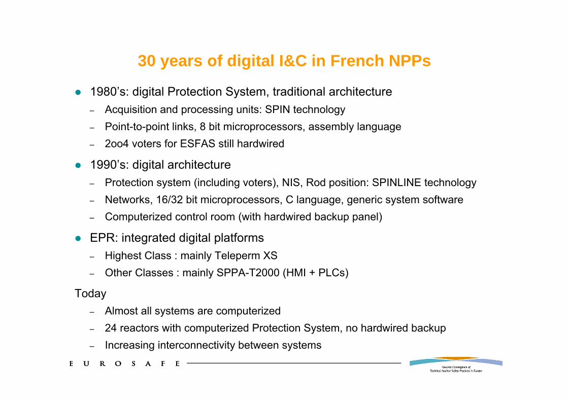
30 years of digital I&C in French NPPs
1980’s: digital Protection System, traditional architecture– Acquisition and processing units: SPIN technology– Point-to-point links, 8 bit microprocessors, assembly language– 2oo4 voters for ESFAS still hardwired
1990’s: digital architecture– Protection system (including voters), NIS, Rod position: SPINLINE technology– Networks, 16/32 bit microprocessors, C language, generic system software– Computerized control room (with hardwired backup panel)
EPR: integrated digital platforms– Highest Class : mainly Teleperm XS– Other Classes : mainly SPPA-T2000 (HMI + PLCs)
Today– Almost all systems are computerized – 24 reactors with computerized Protection System, no hardwired backup– Increasing interconnectivity between systems
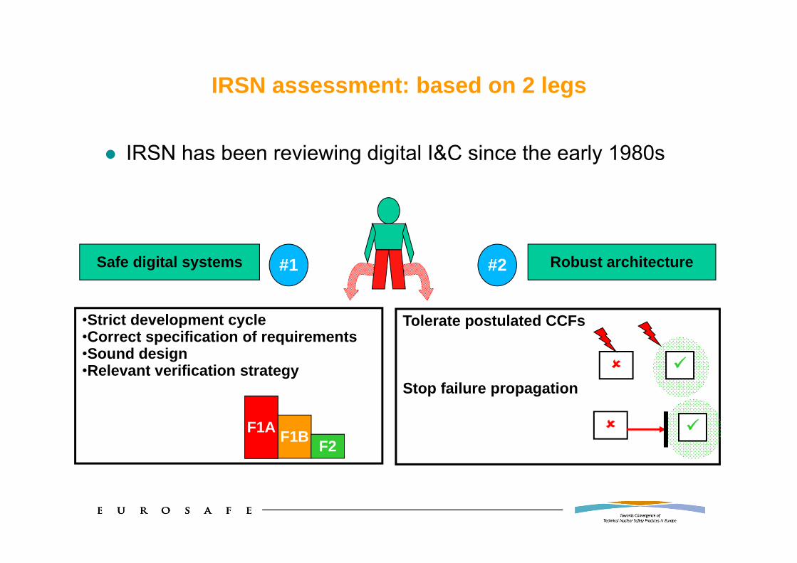
IRSN assessment: based on 2 legs
IRSN has been reviewing digital I&C since the early 1980s
Robust architectureSafe digital systems
•Strict development cycle•Correct specification of requirements•Sound design•Relevant verification strategy
Tolerate postulated CCFs
Stop failure propagation
#1 #2
F1A F1B F2

1rst leg: assessing the safety of each digital system
Software (and programmed logic, e.g. FPGAs) ≠ hardwired logic– Development errors vs. random faults due to wear and tear – Present since the beginning (or will never happen) vs. appear randomly in operation– Infinite set of potential errors (actual ones are unknown) vs. few failure modes HW analysis approach not applicable to SW: no FMEA, no quantified reliability…
Safety software ≠ general purpose software– General: many functions, loose life cycle, loose design principles -> quick release– Safety: dedicated functions, strict development, strong design principles -> verifiability Software may be very reliable provided a dedicated approach is strictly enforced
-> IRSN performs a detailed technical assessment– analyses of design and verification documentation, including source code
For details about 1rst leg, please see paper (same authors) at NPIC&HMIT 2010
2nd leg: assessing the robustness of the architecture
Issues: propagation of failures, CCF
-> Postulate failures of systems or other adverse events-> Study the impact on other systems or on multiple systems-> Check whether the safety functions are still available

Identifying the architecture
I&C systems: roles, functions, boundaries, interfaces, technologies, …
Defense lines: definitions, roles, systems involved in each line
Classification: definition of safety classes, associated requirements, class of each system, …

Architecture diagram (based on public Preliminary Safety Report)
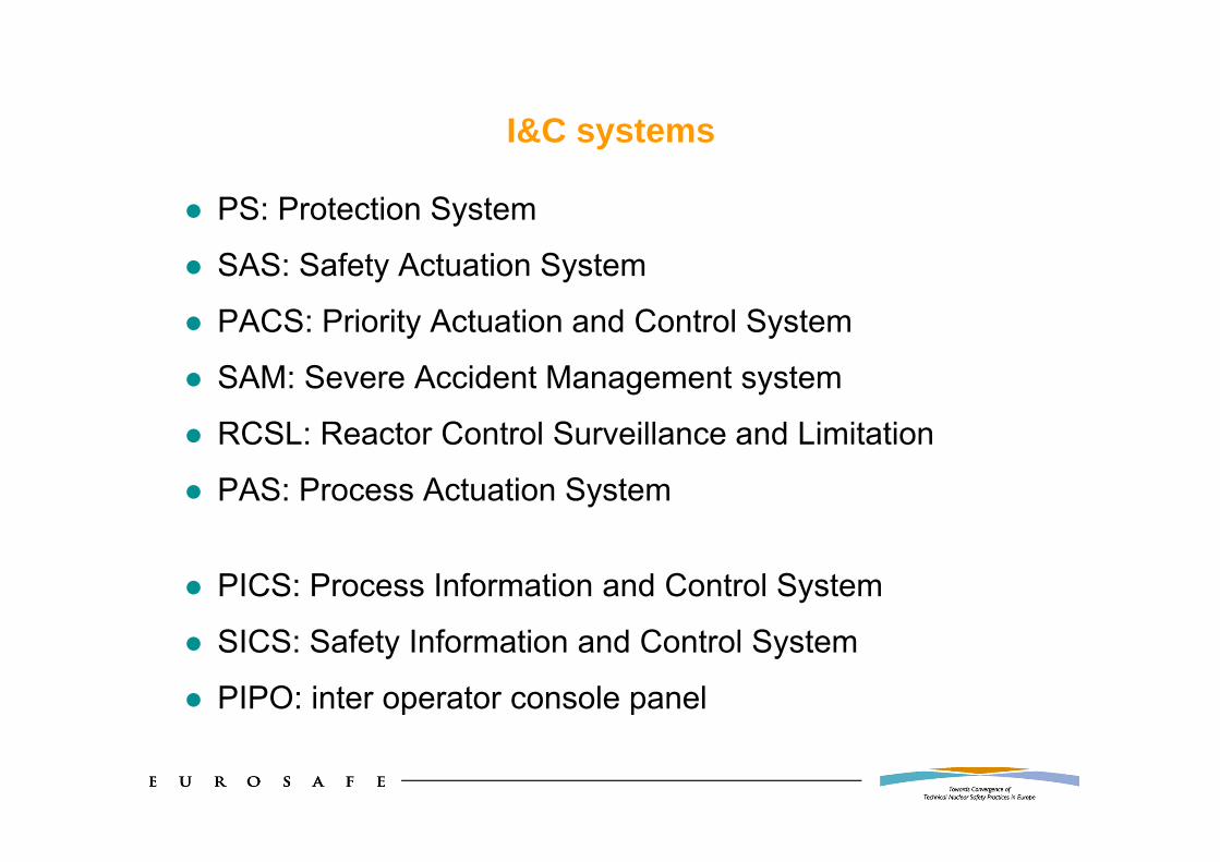
I&C systems
PS: Protection System
SAS: Safety Actuation System
PACS: Priority Actuation and Control System
SAM: Severe Accident Management system
RCSL: Reactor Control Surveillance and Limitation
PAS: Process Actuation System
PICS: Process Information and Control System
SICS: Safety Information and Control System
PIPO: inter operator console panel

Some characteristics of EPR I&C (1)
3 safety classes: F1A, F1B, F2 (+ NC)
3 lines of defense involving I&C- L I: prevention of incidents & accidents (includes limitations)
- L II: prevention of core/fuel meltdown (PCC2 to 4 and RRC-A situations)
- L III: prevention of major and early releases (severe accidents = RRC-B)
2 platforms (families of equipment and related engineering tools)- Teleperm XS from AREVA
mainly for Protection System (F1A) and Limitations
- SPPA-T2000 from Siemens
for post-accidental (F1B), HMI (F2), other F2 and NC

Some characteristics of EPR I&C (2)
FA3: non digital priority management of actuators (PACS)– PACS manages orders from all defense lines and all SC
Extensive use of networks (Terminal Bus, Plant Bus)
Computerized HMI (F2) – Built on general purpose Operating Systems – Used in all plant situations as long as available– Backed up by a non-computerized HMI

Architecture, ideal case
Full independence between any two lines of defense Full independence between any two safety classes
-> Obviously good high level safety principles-> Difficult to achieve in practice
– General plant design -> increased number of defense lines– Finer breakdown in the safety classification– Other technical constraints (next slides)
-> Assessment of independence more difficult than on the first reactor series (only the Protection System had to be independent from the rest of the I&C)

Architecture, constraints (1)
E.g. a valve operated during normal operation for regulation purposes, must be closed when an accident occurs
This implies communication from less to higher classified Such dependencies, coming from the plant design, are
necessarily reflected in the I&C solution
Some actuators are controlled by several Safety Classes or lines of defense
Architecture, constraints (2)
Sensors of the primary circuit Should they be used by only one line of defense ?
(e.g. not by protection system and normal controls)– Straightforward assessment– But need for many additional sensors
That could weaken the primary reactor coolant system
The choice is made during plant design
-> another constraint on the I&C

Architecture, constraints (3)
Some systems have sometimes to be connected to maintenance terminals
Should the maintenance terminal have the same safety class?– Straightforward assessment– But less diagnostic capabilities (highest SC would have the lower
diagnostic capabilities)
Balance to be found
Architecture, constraints (4)
The same operator will cope with normal situations as well as with incidents and accidents
Should the same operating mean (i.e. computerized HMI) be used in both situations ?– Good for Human Factor aspects
But this common HMI introduces dependencies in the I&C between different:– Lines of defense
– Safety classes

Architecture, constraints (5)
An internal hazard like fire or flooding will impact all I&C equipment in the affected zone
Thus full independence would prevent putting in the same fire zone I&C systems belonging to different safety classes or different lines of defense
This would imply – 4 divisions for the PS – Plus divisions for standard I&C, separate from those of PS– Plus separate divisions for severe accident management
This is beyond any current practice

Impact on the assessment
Full independence between lines of defense and between safety classes– is not achievable in practice
– would not necessarily lead to the best overall plant design
The assessment is therefore more difficult than it seemed
Need to accept some exceptions duly justified in terms of safety

Robustness as a new starting point
Need to come back to the basic safety objectives-> ensure that no plausible event affecting a set of I&C devices can
jeopardize the availability of I&C functions
What are the plausible events to consider ?
(i.e. to what should the architecture be robust?)
Categories of plausible events (1)
IRSN has established the following categorization of plausible events, based on the experience of 3 reactor generations
Single failures– Random failures due to physical degradation; all possible failure modes, not only
“graceful failures”
Internal hazards which can be confined– Typically fire or flooding; all possible failure modes have to be considered
Earthquake– Unless proven otherwise; all possible failure modes have to be considered
Common cause failure by electrical propagation through power line– Propagation of electrical faults via the power supplies of I&C
Common cause failure by electrical propagation via the signals– Propagation of electrical faults via electrical link within I&C

Categories of plausible events (2)
Technological common cause failure (CCF)– Simultaneous failure of two or more items of the same model or range, the
root cause being a design error
-> This does not extend a priori to a technical domain in general (if adequate diversity is demonstrated)E.g. failure of all software based equipment, on the sole basis that it includes software, is not postulated
CCF by propagation of erroneous information or by dependency on common implicit information– One device transmitting erroneous data to other devices Regardless of the transmission technology, even if is more sensitive for networks
(which tend to increase the amount of transmitted data)
– Dependency on implicit informatione.g. problems with range limitations, switching from summer to winter time
Tolerance levelRepresents the location of the countermeasure to a given event
Equipment– The piece of equipment can tolerate the event (e.g. seismic qualification)
System– The system can tolerate the event (e.g. a redundant system vs. single failure)
Line of defense– Another system or provision can tolerate the event within the line of defense
considered (e.g. ATWS)
Architecture – The event can impact several lines of defense, but the overall architecture can still
perform the functions (e.g. PICS used for all plant situations and SICS as a backup)
Exclusion– The event is excluded for a given type of equipment (typically the technological CCF
is excluded for components having a “simple” design)– The exclusion must be justified ("excluding" is not "ignoring")

Screening of plausible events (1)
IRSN has applied its assessment methodology to each device x event
And identified the “tolerance level” provided by the architecture
Level 1 level 2Level 0
Single failure
« Sectorizable » hazards
Seism
Technological CCF
Propagation of erroneousinformation
Propagation via power supplyPropagation via electrical signals
System
analog: ExcludedCEP: overallarchitecture
System
Equipement
Line of defence Overallarchitecture
Excluded or reported to level 1
OverallArchitecture
Overallarchitecture
Overall architecture
System
1
2
3
4
5
6
7
8
9
10
11

Screening of plausible events (2)
11 topics (device x event) were then systematically screened
If EDF’s claim was not self evident, a detailed analysis were performed
E.g. topic 7 (propagation of erroneous information at level 1)– IRSN identified issues on the Plant Bus and required justifications/changes
– Analyses involved details far below the overall I&C diagram
E.g. topic 4 (technological CCF on smart sensors)– IRSN identified some smart sensors and requested EDF to postulate a CCF
on any given smart sensor reference
– EDF had to verify that a given reference was not used for the same accident sequence in different lines of defense (otherwise diversify)

Outcomes of the assessment (1)
Conclusions and requests presented by IRSN in 2009 to the standing board of experts and followed up by ASN letter– Addition of an independent mean to validate HMI commands that could
inhibit F1A functions
– Addition of F1B mean to detect postulated failures of computerized HMI (for reliable detection of when to switch to non-computerized SICS)
– Demonstration of non perturbation of the HMI (F2) by NC devices (justifications + changes)
– Backup of SPPA-T2000 F1B functions in a dedicated TXS based system
– Extension of the SICS coverage to risk reduction categories A and B
– Clarification of the operating means available in case of failure of the SPPA T2000 platform during a severe accident
Outcomes of the assessment (2)
In addition during the assessment itself, the technical discussions led EDF to propose some significant improvements– E.g. introduction of a dedicated “SAS Bus” for SAS communications
(rather than using the Plant Bus shared with F2 and NC)
During summer 2010, IRSN received as scheduled the technical proposals and justifications from EDF– The examination of those answers is in progress and has up to now
not led to identifying any new significant architectural issue
Conclusion (1)
Assessment of the EPR I&C architecture proved quite challenging: high degree of interconnectivity, comprehensive digital platforms
A method has been devised and applied to assess safety without needing everything being independent of everything
Reviewing the architecture is only half of the task. It complements the detailed technical assessment of the I&C systems, especially software
Independence and defense in depth must by no mean be considered as a workaround for avoiding a detailed technical justification of safety systems including software
The changes introduced by EDF in the architecture improve safety

Conclusion (2)
Regarding the mid term (beyond FA3), we can note 2 particular issues (among all those raised by the fast evolving technology)
Choice of general purpose computers for the main HMI– Benefits regarding human factors
– But introduces many links between different SC and defense lines
– Fortunately, technologies for safety computerized HMIs are emerging
Trend in the automation industry to propose a versatile architecture with all devices connected to networks– This will increasingly conflict with independence requirements
– Designers of safety I&C should instead identify all communication needs and independence requirements and then implement only the required links