Promoting Critical Reading using Google Tools a Community ...
Upload
goutam-biswasCategory
view
60download
2description

DOT/FAA/AR-06/36 Air Traffic Organization Operations Planning Office of Aviation Research and Development Washington, DC 20591
Assessment of Software Development Tools for Safety-Critical, Real-Time Systems Final Report July 2007 This document is available to the public through the National Technical Information Service (NTIS), Springfield, Virginia 22161.
U.S. Department of Transportation Federal Aviation Administration

NOTICE
This document is disseminated under the sponsorship of the U.S. Department of Transportation in the interest of information exchange. The United States Government assumes no liability for the contents or use thereof. The United States Government does not endorse products or manufacturers. Trade or manufacturer's names appear herein solely because they are considered essential to the objective of this report. This document does not constitute FAA certification policy. Consult your local FAA aircraft certification office as to its use. This report is available at the Federal Aviation Administration William J. Hughes Technical Center’s Full-Text Technical Reports page: actlibrary.tc.faa.gov in Adobe Acrobat portable document format (PDF)

Technical Report Documentation Page 1. Report No. DOT/FAA/AR-06/36
2. Government Accession No. 3. Recipient's Catalog No.
4. Title and Subtitle
ASSESSMENT OF SOFTWARE DEVELOPMENT TOOLS FOR SAFETY-CRITICAL, REAL-TIME SYSTEMS
5. Report Date July 2007
6. Performing Organization Code
7. Author(s) Andrew J. Kornecki, Nick Brixius, Janusz Zalewski Herman Lau, Jean-Philippe Linardon, Jonathan Labbe, Darryl Hearn, Kimberley Hall, Lazar Crawford, (Master of Software Engineering), Celine Sanouillet, and Mathieu Milesi (Exchange Students)
8. Performing Organization Report No.
9. Performing Organization Name and Address Department of Computer and Software Engineering College of Engineering Residential Campus Embry-Riddle Aeronautical University 600 S. Clyde Morris Boulevard Daytona Beach, FL 32114-3900
10. Work Unit No. (TRAIS)
11. Contract or Grant No. DTFA0301C00048
12. Sponsoring Agency Name and Address U.S. Department of Transportation Federal Aviation Administration Air Traffic Organization Operations Planning Office of Aviation Research and Development Washington, DC 20591
13. Type of Report and Period Covered Final Report January 15, 2002–September 15, 2005
14. Sponsoring Agency Code AIR-130
15. Supplementary Notes The Federal Aviation Administration Airport and Aircraft Safety R&D Division COTR was Charles Kilgore. 16. Abstract The objective of the research was to identify the assessment criteria that allow both developers and certifying authorities to evaluate specific safety-critical, real-time software development tools from a system and software safety perspective. The report clarifies the landscape of software development tools with respect to the current aviation system certification guidelines. The research effort proceeded in two directions: (1) collecting data on tool qualification efforts to examine potential future modifications to the existing guidelines and (2) creating software development tool evaluation taxonomy by identifying tool categories, functionalities, concerns, factors, and evaluation methods. The problem statement has four components: (1) industry view, (2) qualification, (3) quality assessment, and (4) tool evaluation taxonomy. The data collected from industry influenced the evaluation process and the recommendations for development tool practices. Selected methods used to evaluate tools have been described. The report presents different categories of tools identified in the course of the research. This categorization is limited to the research scope as guided by DO-178B. Finally, the report defines the structure and the organization of the tool evaluation taxonomy. 17. Key Words
DO-178B, DO-248, Software development tools, Safety-critical systems, Tools assessment, Software development lifecycle, Tool qualification
18. Distribution Statement
This document is available to the public through the National Technical Information Service, Springfield, VA 22161.
19. Security Classif. (of this report) Unclassified
20. Security Classif. (of this page) Unclassified
21. No. of Pages 159
22. Price
Form DOT F 1700.7 (8-72) Reproduction of completed page authorized

ACKNOWLEDGEMENTS
The research team wants to acknowledge the contribution of graduate students of the Master of Software Engineering program at Embry Riddle Aeronautical University: Aber AbuRahma, Rose Atwood, Jared Erwin, Phil Hoden, Tariqul Islam, Sung-Bong Kim, Sameer Lakha, Kim Madler, Adam Moore, Takashi Osako, James Poole, Oliver Rettig, and Joshua Dolecal from Human Factors and Systems program. They contributed to the project by participating in the experiments with the tools, collecting the data, and observations. Support and help of the Federal Aviation Administration (FAA) personnel: Leanna Rierson, Barbara Lingberg, Charles Kilgore, who have been a contributing factor in this research are also acknowledged. An acknowledgement is due to a number of industry representatives from both tool vendors and airborne software developers’ ranks, which contributed to the research providing their comments and observations. Their highly appreciated contribution has been kept anonymous.
iii/iv

TABLE OF CONTENTS
Page EXECUTIVE SUMMARY xiii 1. INTRODUCTION 1
1.1 Purpose and Scope 1 1.2 Objectives 1 1.3 Problem Statement 2
1.3.1 Problem Statement 1—Industry View 4 1.3.2 Problem Statement 2—Qualification 4 1.3.3 Problem Statement 3—Quality Assessment 4 1.3.4 Problem Statement 4—Tool Evaluation Taxonomy 5
1.4 Audience 5 1.5 Research Approach 6 1.6 Document Structure 8
2. BACKGROUND INFORMATION 9
2.1 Software Development Tools 10 2.2 Software Engineering Tools and Their Characteristics 10 2.3 Key Terms Related to Development Tool Qualification 11 2.4 Distinguishing Certification and Qualification 12
2.4.1 The Context of Tool Qualification Requirements 12 2.4.2 DO-178B Development Tool Qualification Framework 14 2.4.3 Industry and Certification Authorities 14 2.4.4 Streamlining Software Aspects of Certification 15 2.4.5 Service History-Based Qualification 15
2.5 Requirements Traceability 16 2.6 Distinguishing Development and Airborne Environments 16 2.7 Tool Operational Requirements 17 2.8 Software Development Tool Categorization 18
2.8.1 Types of Software Development Tools 18 2.8.2 Control Engineering Versus Software Engineering Paradigm 20 2.8.3 Automatic Code Generation 22
2.9 Tool Selection 23 2.10 Software Development Tool Qualification Process 23
v

2.10.1 Tool Qualification Steps 24 2.10.2 Tool Qualification Conditions 24 2.10.3 Compilation and Linking 25
2.11 Discussion of Determinism 25
2.11.1 Interpretation and Definition of Determinism 26 2.11.2 A Formal Approach 28 2.11.3 Predictability Versus Determinism 29 2.11.4 Industry Views on Determinism 31
3. INDUSTRY VIEWPOINT 32
3.1 Software Development Tool Surveys (2002) 32
3.1.1 Development Tool Evaluation Criteria 32 3.1.2 Tool Qualification Considerations 33 3.1.3 Tool Compatibility, Interoperability, and Other Characteristics 34 3.1.4 Tool Training and Documentation 34 3.1.5 Development Tool Evaluation Techniques 34 3.1.6 Development Tool Concerns 35 3.1.7 Need for Additional Tool Qualification Guidance Policy 36 3.1.8 Early Software Qualification in the Development Environment 36
3.2 Software Tool Forum Feedback (2004) 37
3.2.1 Software Development Tool Issues 37 3.2.2 Next Steps 40
3.3 Tool Survey Follow-Up (2004) 40
3.3.1 Tool Qualification Status 41 3.3.2 Limited Survey Response 42
4. DEVELOPMENT TOOL EVALUATION TAXONOMY 42
4.1 Development Tool Evaluation Framework 42
4.1.1 Macroevaluation 43 4.1.2 Microevaluation 43 4.1.3 Metaevaluation 43
4.2 Software Development Tools Evaluation Criteria and Guidance 44 4.3 Software Development Tools Evaluation Methods 45
4.3.1 Categories of Tool Evaluation Methods 45
vi

4.3.2 Literature of Software Evaluation Criteria and Methods 46 4.3.3 Selection of the Evaluation Criteria for the Experiments 51
4.4 Multiple Views of Software Development Tools Assessment 52
4.4.1 Taxonomy View 53 4.4.2 Project View 56 4.4.3 Qualification View 57 4.4.4 Behavioral View 59
5. SOFTWARE DEVELOPMENT TOOLS ASSESSMENT EXPERIMENTS 61
5.1 Tool Selection 61
5.1.1 Structural (Object-Oriented) Tools 61 5.1.2 Functional (Block-Oriented) Tools 62 5.1.3 Omitted Tools 62
5.2 Tool Assessment Experiment Assumptions and Approach 62 5.3 Preliminary Experiments 63
5.3.1 Preliminary Experiments Process Script 63 5.3.2 Preliminary Experiments Evaluation 64 5.3.3 Preliminary Experiment Results 64 5.3.4 Preliminary Experiment Lessons Learned 64
5.4 Controlled Experiments 65
5.4.1 Controlled Experiments Process Script 66 5.4.2 Controlled Experiments Evaluation 66 5.4.3 Controlled Experiments Results 66 5.4.4 Controlled Experiments Lessons Learned 67
5.5 General Observations 68
5.5.1 Limited Number of Experimental Requirements 68 5.5.2 Learning How to Use the Tools 68 5.5.3 Project View Evaluation 68 5.5.4 Value of Automatic Code Generation 68
6. RESEARCH FINDINGS 69
6.1 Problem Statement 1—Industry View 69
6.1.1 What are the Basic Issues Regarding Software Tool Use in the Regulated Field of Safety-Critical Software Development? 69
vii

6.1.2 What is the Industry Opinion on the Current Tool Qualification Process? 69
6.1.3 What Tool Qualification Approaches Meet Safety Needs and are
Acceptable to Both Industry and Certifying Authorities? 69 6.1.4 What Would Help to Encourage Safe Use of Development Tools? 70 6.1.5 What Kinds of Development Tools are Anticipated Being Used in the
Future? 70 6.1.6 What Tools Were Considered for Qualification? 70
6.2 Problem Statement 2—Qualification 71
6.2.1 What Development Tools Have Been Attempted to be Qualified to the DO-178B Standard? 71
6.2.2 Why do Development Tools Need to be Qualified? 71 6.2.3 How to Achieve Qualification for COTS Tools? 72 6.2.4 What are the Barriers of Development Tools’ Qualification? 72 6.2.5 What Factors Need to be Addressed Regarding Development Tools
and Qualification? 73
6.3 Problem Statement 3—Quality Assessment 73
6.3.1 How may the Quality of a Software Development Tool be Assessed From the Perspective of its Use in Safety-Critical, Real-Time System Development? 73
6.3.2 What are the Mechanisms and Methods for Evaluating Software
Development Tool Quality? 73 6.3.3 What Evaluation Criteria Should be Used? 74 6.3.4 How Viable are the Development Tools in Terms of
Long-Term Support? 74
6.4 Problem Statement 4—Tool Evaluation Taxonomy 75
6.4.1 What are the Functionalities of Modern Software Development Tools? 75 6.4.2 How Can the Tools be Categorized? 75
viii

6.4.3 Which Areas are Important for the Development Process? 76 6.4.4 Which Areas of Software Development Tools Need to be Evaluated? 77
7. SUMMARY AND OBSERVATIONS 77
7.1 Summary 77 7.2 Observations 78
8. REFERENCES 81
9. LITERATURE SEARCH RESULTS 84
9.1 Software Engineering Tools 84 9.2 Safety Critical System Development 85 9.3 Standards and Certification of Software Intensive Systems 86 9.4 Real-Time Systems 88 9.5 Software Engineering Issues 88 9.6 COTS Products and their Assessment 89 9.7 Software Evaluation 90 9.8 Avionics Systems Software 91 9.9 Automatic Code Generation 92
10. GLOSSARY OF TERMS 93
APPENDICES
A—Tool Evaluation B—Preliminary Experiment C—Controlled Experiment D—Real-Time Development Tools–Commercial Products
ix

LIST OF FIGURES
Figure Page 1 Example of Tool Landscape 3 2 Stakeholders 6 3 Software Development Tools Workflow 7 4 Tool Categories 19 5 Determinism: Bijection 28 6 Determinism: Surjection and Injection 29 7 Tool Evaluation Criteria 33 8 Tool Evaluation Techniques 35 9 Model of Tool Evaluation Process 43 10 Four Views of Tool Evaluation 52 11 Experiment Platform 63
x

LIST OF TABLES Table Page 1 Design Tool Taxonomy 55
xi

LIST OF ACRONYMS
AC Advisory Circular ACG Automatic code generation ACO Aircraft Certification Office CASE Computer-aided software engineering CAST Certification Authorities Software Team CNS/ATM Communications, Navigation, Surveillance, and Air Traffic Management COTS Commercial off-the-shelf CTGT Configuration table generation tool DER Designated engineering representative DP Discussion paper FAA Federal Aviation Administration FADEC Full Authority Digital Engine Control GALA Generation Automatique de Logiciel Avionique GPU Graphical processing utility HLR High-level requirements IEC International Electrotechnical Commission IEEE Institute of Electrical and Electronics Engineers ISO International Organization for Standardization JAA Joint Aviation Authority LLR Low-level requirements LOC Lines of code MBD Model-based development NASA National Aeronautics and Space Administration OS Operating system PSAC Plan for Software Aspects of Certification PSP Personal Software Process QCG Qualification code generator RTOS Real-Time Operating System SAS Software Accomplishment Summary SCADE Safety-Critical Avionic Development Environment SEI Software Engineering Institute SSAC Streamlining Software Aspects of Certification STC Supplemental Type Certificate TOR Tool operational requirements TQAS Tool Qualification Accomplishment Summary TQD Tool Qualification Development TQP Tool Qualification Plan TSO Technical Standard Order TVR Tool Verification Results UML Unified Modeling Language UTBT Universal Table Builder Tool VAPS Virtual Application Prototyping System
xii

EXECUTIVE SUMMARY
Modern software development tools have direct and growing impact on the effective and efficient development of complex, safety-critical, real-time avionics systems and, consequently, on the safety of the flying public. The objective of tool qualification is to ensure that the tool provides confidence at least equivalent to that of the processes eliminated, reduced, or automated in the certification of the developed airborne software. Existing Federal Aviation Administration (FAA) software guidelines are more restrictive with regard to development tool qualification than they are for verification tool qualification. These existing guidelines for development tools state that the tool must meet the same objectives as the software development processes of the airborne software in the certified system. In addition, the software level assigned to the tool should be the same as the level assigned to the software it produces. These guidelines make it very difficult and expensive to qualify development tools because they do not consider differences between development environments on a general-purpose workstation with a commercial off-the-shelf (COTS) operating system and the dedicated target application environments of the airborne software. This report is intended for use by both industry and the FAA. This research project identifies assessment criteria that allow both developers and certifying authorities to evaluate specific safety-critical, real-time software development tools from the system and software safety perspective. It also determines and evaluates the state of the art in safety-critical software development tools and generates candidate guidelines for software development tool qualification. It creates a software development tool evaluation taxonomy and explores the assessment criteria identifying tool categories, functionalities, concerns, factors, and evaluation methods. The progress of technology drives creation of more sophisticated and complex development tools with analysis and code generation capability, which dominate the software tool market. Using a selection of tools, focusing on object-oriented and block-oriented tools with automatic code generation functionality, the experiments were designed to collect practical data and to facilitate tool assessment and evaluation in the development and execution of selected software projects. The experiments mirrored real-world project problems including lack of COTS tool development data and source code. Two-phased experiments were designed: preliminary experiments were conducted to enable fully controlled experiments for the development of well defined but simple real-time systems in four stages: preparation, model and code development, measurements, and post-mortem. The collected data and observations provided a basis for determination of tool quality and investigated the future use of such tools pointing to the need for modifying the existing qualification guidelines. The results of this research effort show that state-of-the-art software development tools are primarily model-based tools with automatic code generation capabilities. The research identified and categorized these development tools. As the development tools become large and complex multifunctional software suites, existing FAA policies and guidelines for safety-critical avionics software may need to be modified to carry out the qualification. The feedback collected from
xiii

industry shows that, considering the present wording of the certification guidelines, the qualification of development tools is a rather difficult proposition from the technical viewpoint and hardly acceptable from the business perspective. The research identified a relatively short list of qualified development tools. The study was designed to assess the evolving nature of software development tools for safety-critical, real-time systems and to determine how the changing nature and importance of these tools needs to be considered in the preparation of today’s (and tomorrow’s) guidelines for tool qualification and their use in systems certification. The report addresses the environments and technical challenges facing qualification and certification guidelines in the future. It does not, however, provide those guidelines.
xiv

1. INTRODUCTION.
1.1 PURPOSE AND SCOPE.
Most airborne systems (e.g., flight controls, avionics, or engine control) are typical examples of safety-critical, real-time systems. These systems are extremely software intensive and continue to become more complex. They often operate in environments with diverse ranges of temperature, humidity, air pressure, vibration and movement, and are subject to the affects of age, maintenance, and weather. Typical characteristics required of such systems are reliability, fault tolerance, and deterministic timing guarantees. The software for such systems is developed using a variety of tools that must address these issues. Appropriate tools must be selected to meet the needs of a specific project. The quality of the tool and the assurance of tool output are critical for the target system certification. This report, produced under a contract sponsored by the Federal Aviation Administration (FAA), describes research focusing on the initial assessment of software development tools for safety-critical, real-time systems. This research supports policy and guidance development for software-intensive aviation systems in a rapidly evolving software engineering domain that exhibits a proliferation of software development tools. However, this report is not considered FAA policy or guidance—it is research-focused and may be considered as input for future policy and guidance, as appropriate. The scope of the research has been limited to software development tools that have been used, or have a potential to be used, in airborne applications. The principal document guiding software considerations for airborne systems, RTCA DO-178B, defines a software tool as:
“A computer program used to help develop, test, analyze, produce or modify another program or its documentation. Examples are an automated design tool, a compiler, test tools and modification tools.” In section 12.2 of 178B software development tools are as defined in part: “Tools whose output is part of airborne software and thus can introduce errors into that airborne software.”
The software development tools are the focus of this research. However, while concentrating on aviation with its associated certification requirements based on the need for safe and reliable systems, many of the addressed issues might be extended to other domains with mission-critical and safety-critical constraints (such as nuclear, medical, automotive, and military). 1.2 OBJECTIVES.
The main objective of this research project has been to identify the assessment criteria that allow both developers and certifying authorities to evaluate specific safety-critical, real-time software development tools from a system and software safety perspective. Related objectives are to present and evaluate the state of the art in software development tools used to develop safety-critical, real-time systems and to establish a basis for future software development tool qualification guidelines.
1

1.3 PROBLEM STATEMENT.
Modern software development tools have direct and growing impact on the effective and efficient development of complex, safety-critical, real-time avionics systems and consequently on the safety of the flying public. The developed avionics system software must be shown to comply with airworthiness requirements, which include functional, quality of service, and safety requirements. The development processes performed by modern software development tools can be extremely complex and provide opportunities to automate the collection and documentation of evidence that the system requirements are met and that the development processes do not compromise the developed software requirements. Existing FAA software guidelines are more restrictive with regard to development tool qualification than they are for verification tool qualification. These guidelines state that the tool must meet the same objectives of the same software assurance level as the avionics software of the certified system. These guidelines do not consider the differences between development environments and the application environments of the airborne software. As development processes, e.g., model-based development (MBD) and automatic code generation (ACG), become more complex, pervasive, and automatic, the need for qualified development tools and related proof of quality for the developed software will increase. Although the business case cannot compromise the safety case of software development tool qualification, guidance to take advantage of evolving development tool capabilities may also address the business case of software development tool qualification. This could transform the growing cost and quality concerns into savings and enhanced quality and safety. The commercial software development tools market is rather volatile and confusing to the buyer, e.g., tool vendors may claim that a tool is certifiable. For in-house developed tools, even within the same organization, often one division may not be aware of the tools used in another division. The tools produce artifacts in a variety of formats frequently requiring manual and error-prone translation between the tools. Just to show the complexity of such situation, figure 1 presents a sample view of the tool landscape as used by industry in 2002. See section 2.8.1 for a classification of more modern software development tools and appendix D for the real-time development tools evaluated in this report. It is easy to see that developers face problems in an attempt to create a consistent description of the system properties. It should be stressed that many general-purpose, computer-aided software engineering (CASE) tools were created without understanding or considering the required DO-178B process, practically preventing tool qualification under the current guidelines.
2

• Each COTS tool captures a single narrow aspect of the system design/architecture
• System is captured in different forms in different COTS tools
• Proliferation of tools and design notations
⇒System designer must depend on other tools for architectural representation and integrationCustom workarounds, patches, and conversions needed around each COTS tool, in each project
⇒Manual translation between tools causes lot of duplicated effort
⇒Lack of standard design/architecture notations leads to less re-use across SBUsPlatform dependencies get embedded in design, reducing portability
MatlabSimulink
Price
CodeTestSCADE
ESCAPE(EPIC/DEOS)
VALFAC
StateMate
ConfigMgmtBEACONDOORS
UML-Based tools (e.g. Rose)
Requirements ProductPreliminary Design,Analysis
Detailed Design Code,Test
PlatformConfiguration, Test
ForeSight IOGT(ARINC 653)
CORE AUTT
iSMART MatlabRTW
Current Tools: Issues, and Limitations Current Tools: Issues, and Limitations Current Tools: Issues, and Limitations
Figure 1. Example of Tool Landscape (Courtesy of Honeywell Software Solution Lab, Autocode Summit, June 2002)
Several attempts have been made to create a uniform tool environment. Almost each time a new tool is released, claims are made about how its features will allow easy interface with other tools. Reality does not match this idealized picture leaving the need for plenty of gluing between the tools artifacts, i.e., in-house work by the developer to get the tools to work with one another. The elements of industry that develop software-intensive systems for aviation are particularly sensitive to these issues because the products need to be highly reliable and meet certification requirements. By definition, a qualified development tool eliminates, reduces, or automates a process(s) in the software development effort without its output being verified in that development environment. The goal of automation (i.e., using tools) is to develop high-quality software more efficiently. The existing software guidelines defined by the FAA through Advisory Circular (AC) 20-115B [1] and elaborated in DO-178B [2] with additional tool-related guidelines in chapter 9 of FAA Order 8110.49 [3] still encourage discussion. Some in industry consider these guidelines for software development tool qualification too restrictive; for example, DO-178B states that the tool should satisfy the same objectives for the software level as the embedded software of the certified airborne system.
3

The presented research shows the industry perspective on software development tools, the development tools qualification from the perspective of the software aspects of airborne system certification, the development tool assessment and evaluation, and the development tool taxonomy. Considering the above, the research problem statement can be elaborated in the following research questions. The answers to these questions as revealed in this study are presented in section 6. The research questions formulated below identify four closely related areas of research. Problem statement 1 deals with the industry perspective on software development tools. Problem statement 2 studies development tools qualification from the perspective of software aspects of airborne system certification. Problem statement 3 focuses on tool assessment and evaluation. Problem statement 4 concentrates on the tool taxonomy. 1.3.1 Problem Statement 1—Industry View.
• What are the basic issues regarding software tool use in the regulated field of safety-critical software development?
• What is the industry opinion on the current tool qualification process? • What tool qualification approaches meet safety needs and are acceptable to both industry
and certifying authorities? • What would help to encourage safe use of development tools? • What kinds of development tools are anticipated to be used in the future? • What tools should be considered for qualification? 1.3.2 Problem Statement 2—Qualification.
• What development tools have been attempted to be qualified to DO-178B standard? • Why is there a need to qualify development tools? • How to achieve qualification for COTS tools? • What are the barriers to qualification of development tools? • What factors need to be addressed regarding development tools and qualification? 1.3.3 Problem Statement 3—Quality Assessment.
• How may the quality of a software development tool be assessed from the perspective of its use in safety-critical, real-time system development?
• What are the mechanisms and methods for evaluating software development tool quality?
4

• What evaluation criteria should be used? • How viable are the development tools in terms of long-term support? 1.3.4 Problem Statement 4—Tool Evaluation Taxonomy.
• What are the functionalities of modern software development tools? • How can the tools be categorized? • Which categories and functions are vital for the development process? • Which categories and functions of software development tools need to be evaluated? 1.4 AUDIENCE.
The report is primarily intended for use by certification authorities in the development of policy and guidance. The Designated Engineering Representatives (DER) and Aircraft Certification Office (ACO) engineers directly involved in the certification process are also a part of the target audience. In addition, the research outcome will also likely be of interest to program and procurement managers, project leaders, system and software engineers, and all others directly involved in implementing software-intensive, safety-critical, real-time systems. This report identifies some potential contradictions and possible shortcomings in the language of the current guidelines when applied to software development tools of the future. It also highlights related industry approaches toward increased use of software development tools in projects requiring system certification. Figure 2 identifies the stakeholders1 involved in the presented investigation.
1 One needs to distinguish between the applicant, responsible for demonstrating compliance with Title 14 Code of
Federal Regulations regulation, and three categories of developers: airborne system developer, airborne software developer, and tool developer.
5

•Universities•Research Institutes•Industry
•FAA•IEEE•ISO•RTCA•…
Tool Vendors
Applicants -Safety-CriticalSoftwareDevelopers
rese
arch
resu
lts
information
information
regulations / standards
softw
are
tool
s
Software Aspects of CertificationStakeholder Diagram
Approval
Certifying Authorities & DER’s
Airborne System Developers
(Tool Developers)
Figure 2. Stakeholders
1.5 RESEARCH APPROACH.
The research includes data collection, infrastructure decisions, data processing, integration, and synthesis. Over 3 years of research, several aspects of the software development tools were investigated. The overall workflow is presented in figure 3.
6

Tool Categorization(software lifecycle, industry practices, etc.)
Software Tool Reference(extensive list of tools currently being used by industry)
Tool Evaluation Taxonomy(evaluation methods & criteria)
Background Information(standards, qualificationhistory, etc.)
Industry Viewpoint(surveys, interviews, email correspondence, information from tool vendors, etc.)
Tools and PlatformPreparation
(workstation set-up, SW toolacquisition, SW tool installation)
Experiment Preparation
(product requirements design,tool assessment methodologyand mechanisms selection,
process design and associatedscripts write-up, )
Preliminary Experiments
(product development, processscripts execution, and data
collection)
Data Integration
(preliminary data verification andprocessing)
Data Analysis
(calculation, observation,inference, and conclusion)
Experiment Improvement
(Enhanced process scripts,simplified product requirements,and questionnaires creation(Training/Support/ACG) )
Controlled Experiments
(product development, processscripts execution, and data
collection)
SW ProductQuality
Attributes andAssessment
MethodsResearch
(continuinginvestigation onpast and current
researchrelating to this
topic)
Identification of Tool Landscape
Figure 3. Software Development Tools Workflow
The research consisted of several activities, often executed concurrently: • Identification of the Tool Landscape: collection of data on the existing software
development tools (including background information, industry viewpoint, tool categorization, tool reference, and tool evaluation taxonomy).
• Software Product Quality Attributes and Assessment: investigation of the past and
current research on software product quality attributes and assessment methods. • Tools and Platform Preparation: acquisition and installation of sample software
development tools from the selected category (i.e., the design tools with code generation capability).
7
• Experiment Preparation: preparation of the process and procedures for both the preliminary experiments and the subsequent controlled experiments.
• Preliminary Experiments: experimentation with the selected tools. • Experiment Improvement: identification of development tool assessment methodology
and related assessment mechanisms. • Controlled Experiments: controlled experiments with the selected tools and data
collection. • Data Integration and Analysis: analysis of the data and documentation of the process and
results in this report. The tool taxonomy involves research not only on existing tools used by the aviation industry, but also on generic software quality attributes and assessment methodologies. The research involved exploration of current regulations and guidelines related to airborne software and their accepted meaning. A number of surveys, phone conferences, and e-mail exchanges were used to collect the data, and subsequently to validate the findings. 1.6 DOCUMENT STRUCTURE.
This report consists of eight main sections: • Section 1 provides introductory material, including the purpose and scope, objective,
problem statement, audience, and research approach. • Section 2 describes the key terms related to the research topic, the development tool
qualification framework, the development tool categorization, current tool qualification process, and discussion of determinism.
• Section 3 describes the industry viewpoint on the use and qualification of software
development tools based on surveys and discussion with the industry representatives. • Section 4 describes the development tool taxonomy presenting description of criteria and
methods for tool assessment. The section presents four distinctive, but related, views on the software development tools evaluation. The supporting material is included in appendix A.
• Section 5 describes the experiments carried out with a group of developers using six
different software tools selected for the study. The detailed experiment description and results are provided in the appendices. This section describes the scope, experimental project requirements and constraints, data collection process, evaluation methods, and the collected results.
8
• Section 6 provides the research findings in the form of answers to questions formulated in the problem statement at the onset of the research.
• Section 7 contains the summary and observations. • Section 8 lists the references. • Section 9 lists the related documents and the results of the literature search categorized
into nine topical areas. • Section 10 is a glossary of terms used in the project. Four appendices accompany this report. Appendix A provides additional information on the evaluation taxonomy with proposed evaluation tables. Appendices B and C provide detailed information on the experiments with the selected tools. They include project requirements, collected data, observations, process scripts, and questionnaires. Appendix D includes a selected list of commercially available products from the development tool category selected for research. Note: Due to confidentiality and legal concerns, except for brief introductions in section 5.1 and the list compiled in appendix D, the commercial tools are not identified. The purpose of this research has been to study general assessment criteria—not to promote or disparage any particular tool. The specific tools were used as an experimental platform to gain appropriate insight. 2. BACKGROUND INFORMATION.
The software development process consists of a series of translations between various artifacts, leading ultimately to the executable code. The goal is to accurately implement the systems requirements allocated to software without introducing faults or errors. Accurate implementation of a system assumes that the system requirements themselves are accurate and have been validated (i.e., the system requirements should be complete, correct, traceable, verifiable, comprehensive, and unambiguous). The concept of building a software-intensive system by developing the structural and behavioral models of the system software is a leading theme in contemporary literature and practice. By subsequent analysis of these models, the developers can get assurance of their appropriate behavior and correct functionality, thus, provide a credible base for the final system implementation. This approach also alleviates the issue of less-than-perfect requirements, since the analysis of the models may lead to the discovery of missing, incomplete, confusing, contradicting, or incorrect requirements. Software life cycle artifacts range from textual representation of requirements, to graphical models of the system and software structure and behavior, to algorithms represented as graphics or mathematical and logic formulas, to textual code representation, to binary version of the executable code. In the past, the translation between various artifacts was done manually. The translation relied solely on a developer’s skills and ingenuity but introduced human error.
9

2.1 SOFTWARE DEVELOPMENT TOOLS.
A variety of tools have been developed to assist software developers in these translation tasks. In the past, compilers and interpreters replaced manual translation of algorithmic source code into machine code. The linkers and loaders replaced manually entering a series of zeros and ones by translating the machine code into the target executable code. In some scenarios and certain types of systems (e.g., well-defined control systems), the design tools with code generation capability are replacing manually written source code based on design algorithms. Patterns are continuously being developed that expand the type and domain application of these algorithms. Experience, combined with verification activities (manual and automatic), has given developers confidence that the source code is translated into its equivalent binary image. One challenge is to accept the notion that it is practical to trust similar translation on a higher level of development hierarchy: from design constructs to the source code. In an aviation environment, another challenge is to demonstrate to the certification authorities why a translator tool can be trusted in lieu of completely verifying the translator’s output. 2.2 SOFTWARE ENGINEERING TOOLS AND THEIR CHARACTERISTICS.
Software engineering tools, often known as CASE tools, provide assistance in the development of software and systems. A software engineering tool is defined as a computer program used to help develop, test, analyze, or maintain another computer program or its documentation. The current state of the art is exemplified by a variety of tools that often support more than one process of the software development life cycle. If properly designed and used, software tools may eliminate or reduce the errors that are often introduced in software life cycle data. On the contrary, an inferior and or improperly used tool may result in a faulty end product with potential significant impact on target system reliability and safety. There have not been many comprehensive efforts on tool evaluation and assessment other than an occasional paper at technical conferences reporting on experience with individual tools. Exceptions are the Institute of Electrical and Electronics Engineers (IEEE) documents [4 and 5] describing the recommended practice for adoption and guidelines for CASE tools selection, and DO-178B [2] that addresses software considerations in airborne systems and equipment certification. Also, the Software Engineering Institute (SEI) published a technical report [6] that provides a starting point for tool assessment, proposing the tool taxonomy and an evaluation framework. Desired characteristics of modern tools include multiuser development, shared information repository, integration with external tools and applications, requirements modeling, executable specifications, use of established software engineering notations, reliable code generation, performance analysis, interface with target for downloading and debugging, and verification and validation of the system. An important issue is whether a specific tool is really facilitating the product development for an experienced developer or only holding hands with an inexperienced user with no special value added. In either case, the resulting target code depends heavily on the usability, correctness, and precision of the tools used for the code development.
10

2.3 KEY TERMS RELATED TO DEVELOPMENT TOOL QUALIFICATION.
Certification and qualification are defined in DO-178B [2] and chapter 9 of FAA Order 8110.49 [3]. Certification is a well-understood concept in the airborne system developers’ community. However, communications with industry representatives have shown that there are variations in understanding and interpretation of the concept of tool qualification. The term software development tool is commonly used. DO-178B defines software development tools as: “Tools whose output is part of airborne software and thus can introduce errors.” However, the interpretation of the term tool qualification might vary from one organization to another. For research purposes, it is important to establish a sound definition. From the American Heritage Dictionary® of the English Language, 4th Edition, Copyright© 2000 by Houghton Mifflin Company, to qualify means:
“to describe by enumerating the characteristics or qualities; or to declare competent or capable.”
Within the context of this research, the latter definition is more applicable. According to the definition given in DO-178B:
“Tool Qualification - The process necessary to obtain certification credit for a software tool within the context of a specific airborne system.”
while: “Certification credit - Acceptance by the certification authority that a process, product or demonstration satisfies a certification requirement.”
Therefore, qualification is a supplementary process the applicant may elect to follow in a course of certification for the airborne system. Moreover, qualification, if claimed, is considered as a requirement to get the system certified. There is a significant amount of work involved to qualify a tool. Note that numerous development tools have been used successfully in certification projects without being qualified since the use of these tools within their projects’ context did not require qualification (see chapter 9-3 of FAA Order 8110.49 [3]). Further explanation of the purpose and the need of tool qualification can be found in section 12.2 of the DO-178B:
“The objective of the Tool Qualification is to ensure that the tool provides confidence at least equivalent to that of the process(es) eliminated, reduced or automated.” “A tool may be qualified only for use on a specific system …Use of the tool for other systems may need further qualification.” “Only those functions that are used to eliminate, reduce, or automate software life cycle process activities, and whose outputs are not verified, need be qualified.”
11

2.4 DISTINGUISHING CERTIFICATION AND QUALIFICATION.
The above definitions imply that the purpose and results of a certification and a qualification are different. A certification declares that the system or product containing the target software meets assurance objectives to be used in an aircraft or avionics application. On the other hand, qualification is used to ensure that a software life cycle process automatic by use of the tool will result in the same or higher-quality output as if the process had been performed manually. A qualification is defined for a specific task in a specific project. There is no central repository that maintains a listing of previously qualified tools. Only the applicant, who qualified a tool within the scope of a specific project, has or owns the necessary data. The research team identified only a handful of development tools that have been qualified. In addition, the obtained information is anecdotal based on personal contacts and word of mouth rather than documented in a way that the research team could examine in detail. The only information the research team was able to obtain were statements to the effect: that Tool X was qualified while used on Level-Y certified system Z by applicant W. Occasionally, additional information was conveyed in a form of brief e-mails discussing the qualification approach or other details. More often, a follow-up was unanswered. Efforts to get access to specific documentation were unsuccessful. It may be hypothesized that the main reasons for that are intellectual property rights and business red tape. Why were there only a handful of attempts to qualify development tools? The research shows that there are more qualified verification tools. The requirements for qualifying verification tools are less strict than those for development tools. Another issue is that of economics. In the aviation industry, methodologies and design approaches typically do not last longer than two airplane programs (10-14 years). Therefore, making a large cost investment in qualification of a tool cannot be spread over many programs to get a good return on investment. Some companies stated that they started down the path to development tool qualification, but stopped after estimating2 the costs of doing this under current guidelines. 2.4.1 The Context of Tool Qualification Requirements.
Tool qualification guidance, as defined in FAA Order 8110.49 chapter 9, provides further clarification when a tool should be qualified:
“There are three questions to ask to determine if a tool needs qualification. If the answer is “Yes” to all of the questions below, the tool should be qualified:
(a) Can the tool insert an error into the airborne software or fail to detect an existing error in the software within the scope of its intended usage? (b) Will the tool’s output not be verified as specified in Section 6 of DO-178B?
2 Software development tools are claimed to cost 20 times more to qualify as verification tools (internal data from
Honeywell, ERAU/FAA Software Tool Forum, Bill Potter presentation, slide 13).
12

(c) Are processes of DO-178B eliminated, reduced, or automated by the use of the tool? That is, will the output from the tool be used to either meet an objective or replace an objective of DO-178B, Annex A?”
According to the collected industry feedback, the following DO-178B guideline for the tool is considered to be overly restrictive:
“If a software development tool is to be qualified, the software development processes for the tool should satisfy the same objectives as the software development processes of airborne software.”
(See DO-178B section 12.2 and its further elaboration in FAA Order 8110.49, chapter 9.) The main industry argument was that the tool software and the application software are operating in different environments, and as such, they should not be required to meet the same objectives. To soften this restriction, the guidelines allow applicants, if justified, a reduction of the software level, e.g., from Level A to B. Such approach results in reduction of the number of objectives that the tool software must meet. It is clear that a software development tool is used to transform an input artifact into output, thus generating another form of the software. If this transformation has an impact on the final airborne product, the development tool may need to be qualified; but only if the transformation output is used to eliminate, automate, or replace a DO-178B objective and would not be otherwise verified. The current process mandates verification after each transformation. Some of the industry representatives commented about the lack of incentives to expend a significant effort on qualification of a development tool, when a smaller effort on output verification leads to the same outcome. However, the data on qualification effort were not available. Thus, the above comments are only an opinion. On the other hand, one could see other benefits of using a qualified tool in the long run (cost saving, error reduction, process automation). A business case might be more easily made for qualification if it would be possible to qualify a tool one time, to be used on multiple projects. Unfortunately, the current language of DO-248B [7] states:
“The certification authority considers the software as part of the airborne system or equipment installed on the certified aircraft or engine; that is, the certification authority does not approve the software as a unique, stand-alone product.”
In addition, DO-178B [2] states:
“A tool may be qualified for use only on a specific system where the intention to use the tool is stated in the Plan for Software Aspects of Certification. Use of the tool for other systems may need further qualification.”
These two quotes may be interpreted to mean that no software, and by extension no software development tool, could be certified or qualified by itself. Software should be associated with a
13

specific airborne system. In addition, tool qualification is done on a system-specific basis. However, FAA Order 8110.49 [3] and AC 20-148 [8] on reusable components promote the concept of reusability of software components, and by extension, tools. Initial approval of the software component should occur in context with a specific airborne system. The practice of not packaging tool data separately, close coupling of the tool and the application, and tool data ownership issues3 make reusability for tools much less likely. 2.4.2 DO-178B Development Tool Qualification Framework.
In 1980, RTCA convened a special committee (SC-145) to establish guidelines for developing airborne systems and equipment. They produced a report, “Software Considerations in Airborne Systems and Equipment Certification,” which was subsequently approved by the RTCA Executive Committee and published in January 1982 as the RTCA document DO-178. After gaining further experience in airborne system certification, the RTCA decided to revise the previous document. Another committee (SC-152) drafted DO-178A, which was published in 1985. Due to rapid advances in technology, the RTCA established a new committee (SC-167) in 1989. Its goal was to update, as needed, DO-178A. SC-167 focused on five major areas: (1) Documentation Integration and Production, (2) System Issues, (3) Software Development, (4) Software Verification, and (5) Software Configuration Management and Software Quality Assurance. The resulting document, DO-178B, provides guidelines for these areas. Also, a key addition to this version of the DO-178 series is the concept of development tool qualification for which SC-167 decided that the qualification process would be the same as the airborne software. 2.4.3 Industry and Certification Authorities.
The industry and certifying authorities are actively engaging in discussion on the topic of development tool qualification. Several software tool vendors are working with avionics developers, certification authorities, and designated engineering representatives to identify approaches to practically address development tool qualification. The Certification Authorities Software Team (CAST) documented several positions (available on the FAA website at http://www.faa.gov/aircraft/air_cert/design_approvals/air_software/cast/cast_papers). The CAST position papers have been coordinated among the software specialists of certification authorities from the United States, Europe, and Canada. However, they do not constitute official policy or guidance from any of the authorities. These documents have been provided for educational and informational purposes only and should be discussed with the appropriate certification authority when considering use for actual projects. Specifically, CAST position paper 13 [9] “Automatic Code Generation Tools Development Assurance,” reflects observations closely related to those described in this report:
“More precisely, the primary issue for an ACG tool is the production of source code that does not comply with its requirements, but can still be compiled without
3 The tool data owner may not be willing to share the tool data or allow it to be shared (by the tool vendor) with
other applicants or developers who may be competitors.
14
any error detected and is executable. For airborne software the same event can occur, but it’s not the only one. Halts during execution, overflows, variations in time response, hardware and software incompatibilities, hardware failures, unbounded recursive algorithms, bad stack usage, resource contention, task conflicts, bad interaction with others systems, etc., are examples of issues which may jeopardize flight safety, if they appear in aviation software. However, these types of errors may not have any influence on the flight safety, if they occurred in the ACG tool that generated the aviation software.”
And subsequently:
“The applicant should demonstrate that the tool is designed and developed in such a way that erroneous functioning of the operating system cannot produce unintended or erroneous code (e.g., showing tool operational requirements in abnormal conditions). Neither can it jeopardize determinism properties of the tool (i.e., the produced code should not differ when the input data does not, as previously mentioned).”
2.4.4 Streamlining Software Aspects of Certification.
One of the presentations at the National Aeronautics and Space Administration (NASA)/FAA Streamlining Software Aspects of Certification (SSAC) Workshop III (1999) discussed the recommendations for tool qualification. As a result of an extensive survey, the SSAC team recommended that the FAA should clarify compliance requirements and intent for tool qualification. In addition, it was recommended that the FAA should clarify the definitions of development and verification tools. The materials included in DO-248B [7] and FAA Order 8110.49 [3] address this recommendation, though some could argue that further progress of the clarification could be made. Another recommendation was that the FAA and industry should investigate techniques for tool qualification that will allow qualification to be faster and cheaper. Additionally, it was recommended that the FAA should determine the feasibility of a national repository for qualified tools and the acceptance criteria for the use of these tools. The presented research addresses many of these comments. 2.4.5 Service History-Based Qualification.
An alternative qualification method, using service history, is addressed in both DO-178B Section 12.3.5 [2] and DO-248B discussion paper (DP) 11 [7], also referenced in chapter 9-6.i of FAA Order 8110.49 [3]. This method can be used only for software that has been used for a period of time under controlled conditions. These documents are not clear regarding what the applicant has to supply to get that type of qualification. New research on service history [10] provides additional guidance on this topic. CAST paper 1 [11] elaborates on product service history attributes such as duration, amount and quality of data, number of errors, number of modifications, change control, contributing to the product acceptability, and thus obtaining certain certification and qualification credit. However, implementation of such an approach is still a matter of interpretation and must be agreed upon between the applicant and the certifying authority on a case-by-case basis.
15

2.5 REQUIREMENTS TRACEABILITY.
The guidance presented in Section 5.5b,c of DO-178B [2] describes the need for traceability between high-level (HLR) and low-level (LLR) requirements and also traceability between LLR and the source code. Interpreting this guidance for the software development tools with automatic code generation capability, there is a need to establish assurance that the software development artifacts produced by the developer are correctly and completely translated into the generated source code. It is also important to ensure that additional code, which does not trace to the requirements, is not added. The issue is to ensure that all the model components have equivalent components of the code (data structures, functions, objects, messages, events, modules) and all code components have their equivalent design model item (depending on those used by the tool modeling notation). As per DO-178B [2], safety-critical software is required to exhibit the quality of traceability in order to be accepted. Without any automatic tool assistance, the demonstration of traceability needs to be done manually for all artifacts generated throughout the development cycle. Since traceability is very time-consuming, it would be an ideal task to be automatic by a tool. The tools under study provide functionality for the user to input their design graphically as a model, and generate the source code from the specified model. If the development tool is qualified to the appropriate software level, then the process of transformation from model to source code may be accepted and the developer may be relieved from performing this task otherwise. The experiments described in section 5 address the feasibility of developing guidelines for how a development tool can demonstrate its effectiveness in assisting developers to comply with the DO-178B objectives for traceability. A brief search of IEEE Digital Library conference proceedings and professional journals (COTS Journal and RTC Magazine) points to numerous recent articles describing evolutionary trends of using tools with code generation capability to replace manual coding. This seems to indicate that the times of handcrafting the entirety of source code will soon not be a viable option for industry. As described, regardless of the development approach, a development tool will need to have automatic code generation capability to compete in the market. The quality of the transformation is critical for overall assessment of software development tool quality and the airborne software’s compliance. Such features as determinism, correctness, robustness, and conformance to standards will be considered as the assessment characteristics. The tool’s extent in ensuring traceability between artifacts generated from one development process to another can be a starting point to make the arguments about tool quality. 2.6 DISTINGUISHING DEVELOPMENT AND AIRBORNE ENVIRONMENTS.
Software development tool output has a direct impact on developed airborne software. Thus, it is imperative to ensure the correctness of a tool’s output. However, there is a major difference between tool software and embedded target software. The tool software generally operates in a general-purpose workstation environment, which is entirely different from the target software environment. The tool is not embedded; instead, it runs typically under a conventional COTS operating system. In fact, the development tool can be considered a ground-based system and
16

the critical consideration for the tool is the integrity and correctness of the generated artifact. In this respect, the tool software is similar to software used in ground-based systems. In the case of embedded software running on an airborne target computer, if nontested (and faulty) code is executed, the behavior of the software could be erroneous, which could impact the system safety. A consequence of an unintended activation of nontested (and faulty) code for a tool may have a safety consequence only when erroneous code would be generated. To avoid this impact, one of the development tool requirements must be to generate code only in normal situations, when a tool operates without failures. The tool may exhibit errors during development due to operating system hang-up or an outside factor (e.g., network traffic, virus). Typically, there are no constraints related to timing as long as the correct output will be produced. The most critical property for the development tool is the integrity of the data. This makes the development tools similar to ground-based systems, e.g., like those handling aeronautical databases or processing health usage and monitoring systems data. Current DO-178B wording does not seem to take into consideration the distinction between errors exhibited in the development environment and errors exhibited in the target airborne environment. Perhaps possible guidelines would consider these characteristics using the approach elaborated in DO-278, which addresses nonairborne Communications, Navigation, Surveillance, and Air Traffic Management (CNS/ATM) systems [12], and in DO-200A, which describes processing of aeronautical data [13]. 2.7 TOOL OPERATIONAL REQUIREMENTS.
The objectives of the development tools software verification process are different from those of the verification process for target software. The tools HLR correspond to the tool operational requirements (TOR) rather than the requirements of the target system. Verification of software development tools may be achieved by (1) review of the TOR and demonstration that the tool complies with its TOR under both normal and abnormal operating conditions and (2) using a combination of requirements-based and structural coverage analysis, as appropriate. Section 12.2.1 of DO-178B [2] and CAST position paper 13 [9] provide further clarification. For the development tool, the required TOR is a detailed requirements document that is traced to the design, code, and test cases of the tool itself. Despite several attempts to receive an example TOR from industry, this data was not available. In the place of the actual TOR, four basic functionality items for the development tool with automatic code generation capability have been identified: • The tool allows a developer to generate the software HLR and design, i.e., architecture
and software LLR, by using notation-supporting specific development methodology. • The tool allows a developer to verify correctness of the design with respect to the
software HLR. • The tool allows a developer to confirm the dynamic behavior of the design (model
execution).
17

• The tool allows a developer to generate code. This is intended to be a generalized list of functions that can apply to several tools. Each of these items can be further analyzed in detail to determine the refined list of the functionalities, which in turn can be assessed in a practical evaluation experiment. The questionnaires and observation in the experiment were designed to extract these data. 2.8 SOFTWARE DEVELOPMENT TOOL CATEGORIZATION.
DO-178B [2] identifies three software life cycle processes: (1) planning (defining and coordinating the activities), (2) development (producing the artifact), and (3) integral processes (software verification, configuration management, quality assurance, and certification liaison). The system requirements allocated to software are the starting point for the software development. DO-178B Section 3.2 identifies four processes of the software development process: • Software Requirements • Software Design • Software Coding • Integration with Hardware 2.8.1 Types of Software Development Tools.
DO-178B [2] allows for flexibility in the development processes. The current practice of software engineering leads to the following broad classification of the software tools used in a typical software development life cycle (figure 4): • Requirements tools • Analysis tools • Testing tools • Design tools • Implementation tools • Target tools Also see appendix D for the specific software development tools evaluated in this report.
18

RequirementsTool
StructuralDesign
Tool
FunctionalDesign
Tool
typically with code generator
functionality
ImplementationTool
TestingTool
Target(with RTOS)
or/and
Tool Categories
AnalysisTool
e.g.: VxWorks
QNXOSE
IntegrityLynxOS
e.g.: CodeTestTestRT
VectorCastInsure++
Integrated Development Environment
(IDE)e.g.:
TornadoMulti
e.g.: RhapsodyRoseRTSTOODArtisan
e.g.: SCADEMatlab
BEACONSildex
e.g.: RapidRMATimeWiz
e.g.: Reqtify
DOORSSpecTRM
DOME
Figure 4. Tool Categories
Modern tools are rather complex and their functionality spans across typical tool categories. The following examples identify the specific functionalities provided by the category. • The requirements category includes tools used early in the life cycle to identify and
specify the software requirements. Also included are the tools that help to determine correctness of the requirements using semi-formal models, even though some could argue that such tools belong more to the analysis category (functionality examples: definition, specification, interface analysis, requirements formal modeling, properties verification, traceability, version management, etc.)
• The analysis category includes tools used for analysis of software behavior and timing,
typically before and after the product is developed. As aviation software is always developed within the system context, analysis tools typically deal with the system requirements (functionality examples: performance, timing, sizing, simulation, etc.)
• The testing category spans over the entire life cycle since the testing must deal with all
software artifacts (functionality examples: coverage, test case generation, etc.) • The design category includes tools that support executable models and are used for
requirements verification, design implementation, code generation, and the development of documentation and test cases (functionality examples: modeling the system using applicable graphical notation in form of blocks, objects, diagrams, code generation, documentation, reuse, etc.)
19

• The implementation category includes all support required to take the computer code and transfer it to the executable program (functionality examples: Integrated Development Environment—editor, compiler, debugger, linker, loader, browser, target customization, etc.)
• The target category includes application run-time support software components that are
not considered to be development tools in the sense of DO-178B definition, since they are clearly components of the target system (functionality examples: run-time support: real-time operating system (RTOS), board support package, libraries, etc.)
Tools that can be classified into the above design, implementation, or target categories support the DO-178B coding and integration processes. Many modern design tools generate code as well as test cases. They frequently support executable models with options to verify various requirements properties. It often happens that a system already produced may be reused/reengineered, so many tools provide a vehicle for architectural and design pattern use. The boundary between the tool categories is frequently fuzzy. There is growing tendency to work at a higher level of abstraction using design and analysis models as the source code, relying on automatic code generation and compilers to produce target software. MBD seems to be the Lingua Franca of modern software engineering. The research discovered that industry frequently uses simple tools of rather limited functionality developed in-house. Such tools typically help translate software artifacts from one format to another. Due to intellectual property constraints and business practices, it is difficult, if not impossible, to obtain specific information about such tools. 2.8.2 Control Engineering Versus Software Engineering Paradigm.
During the design of a real-time system, it is important to be aware that there exist two distinct classes of modern systems exposed to environmental stimuli [14]: • Interactive—the computer system determines the pace of operation by granting or
allocating resources to clients on request when feasible (operating systems, databases); the concerns are deadlock avoidance, fairness, and data coherence.
• Reactive—the system environment determines the pace of operation while the computer
system reacts to external stimuli producing outputs in a timely way (process control, avionics, and signal processing); the concerns are correctness and timeliness.
Software engineers are very familiar with the concepts of operating systems, programming languages, and software development methodologies, and notations are naturally inclined toward interactive systems. The proliferation of object-oriented methodologies is replacing previous procedural approaches. The graphic notations supported by these techniques allow developers to represent the software of the target system as a set of components that are easy to translate into programming constructs (modules, objects, methods, functions, procedures, and data structures) using automatic code generation functionality of the tool. The developer needs to have full
20

understanding of the generated target code and often needs to fill in the framework generated by the tool with specific code in the target language. Control engineers, on the other hand, consider the system as a dynamic model consisting of well-defined blocks of specific functionality (logic, arithmetic, and dynamic) reflecting the properties of reactive systems. The data flow paradigm of the model supports its simulation and analysis of behavior. Subsequently, the model can be translated automatically into an equivalent code, typically without any additional developer involvement. Software engineers, concentrating on computer operations, are more accustomed to interactive systems, while control (or system) engineers, who are educated in control theory, are focusing on reactive systems, which may be called a software engineering or a control engineering paradigm, respectively. Unfortunately, most complex, safety-critical, real-time systems include characteristics of both paradigms. There is no unified theory to represent both paradigms in a smooth way. This dualism is reflected in the variety of modern software development tools, which attempt to bridge the gap. The challenge of the contemporary tool market is to cater to these software and control engineers with the tool providing appropriate support for both paradigms. The gap between software and control professionals makes communication of critical design decisions difficult and may be one of the causes of misunderstandings, unacceptable for safety-critical system design. Tool categorization reflects these diverse viewpoints of safety-critical, real-time system developers resulting from their differing backgrounds. Two of these viewpoints are generally related to software engineering (object-oriented view) and control engineering (functional or block-oriented view) in this document. The development tools selected for detailed study, can be categorized into two groups: • Those using a function-based, block-oriented approach • Those using structure-based, object-oriented approach With the function-based, block-oriented approach, the initial design is first specified in a form of diagrams representing the system functions (with comparative and mathematical symbols). The diagrams are then used to simulate the system behavior and evaluate its performance. Once the user is satisfied with the design, an automatic code generator translates the model and the resulting target source code is produced that reflects the rules specified in the diagrams [15 and 16]. With the structure-based, object-oriented approach, the initial design structure and behavior are documented as a collection of models using object-oriented diagramming notations, such as class diagrams, sequence diagrams, and state diagrams. As in the functional approach, the resulting diagrams are used to validate the system behavior through animation or simulation and then to generate the target source code. The standardized Unified Modeling Language (UML) notation is widely used [17 and 18].
21

Modeling can be used throughout all the life cycle processes. Modern software development methods rely on building conceptual models of the software system and analyzing the models (using simulation, animation, and semiformal or formal model checking) before translation to conventional programming language format. Due to this fact, the concept of using MBD is central to current design and verification practices. Modern software development tools typically address the use of modeling throughout the development life cycle. 2.8.3 Automatic Code Generation.
The investigation concentrates on software development tools, as defined in the DO-178B. Once the requirements are developed and validated, the tools in the design process will facilitate orderly and correct translation of the requirements into executable code. This is the process where most of the development tools are used. An automation of these tasks is very much in demand. The tools with automatic code generation capability are the major focus of this research. The potential benefits of using a qualified code generation tool include reducing the manual labor-intensive unit tests and the software module reviews that add to the certification cycle time and costs. The research presented in this report concentrates on the design process limited to the following two categories of design tools (see section 2.8.2): functional/block and structural/object. Both categories include a graphical user interface that allows the user to specify a design in a graphical or textual manner, and a set of functionalities to save, load, modify, and execute (or animate) such representation. Both typically include target code generation capability, and thus, they are not treated as separate categories. 2.8.3.1 Structural-Based Software Design and Modeling Tools.
This category, preferred by engineers with software and computer background, contains all commonly used design tools based on structural decomposition. The tools from this category are based on object-oriented decomposition and UML-like modeling of the system, allowing the software developers to create a model describing both the structure and behavior. The structural-based tools are software development-oriented and match the interactive paradigm. 2.8.3.2 Functional-Based Software Design and Modeling Tools.
This category, preferred by engineers with system and control background, contains all commonly used design tools based on functional decomposition. These tools allow the domain specialist (e.g., control engineer) to build a model describing the system functionality, represented as block diagrams, with their input-output transformations. The tools of this category are more system control than software development-oriented and conform to the reactive paradigm.
22

2.9 TOOL SELECTION.
The implications of the selection and identification of the actual products for evaluation and analysis have been discussed with industry representatives and certification authorities. The specifics are detailed in section 5, where experiments with the selected tools are described. The documented categorization (see figure 4) shows that the development tools have wide-ranging functionalities and can be applied in various processes of the life cycle. The design process is of specific interest to the aviation industry, thus a decision was made to focus the study on design tools. Currently, based on vendor information, industry survey, and follow-up contacts, only very simple tools or selected tool functionalities related to either scheduling or configuration tables or code generation have been qualified. According to several informal exchanges with industry, many of the modern COTS software development suites have actually been used in the creation of software artifacts on several certified projects without going through the qualification process. Functional, block-oriented tools allow developers to represent the system and analyze its behavior, as the base for either manual creation or automatic generation of the target code. The industry also shows an increasing interest in using object-oriented notation and related structural-based tools. The UML notation from the commercial world has been gaining popularity in the safety-critical industries and tools of this category have been also used on certified system development. Unfortunately, the majority of commercial tools are not specifically built for the safety-critical market, and thus, it may be nearly impossible to qualify them following the current DO-178B process. These tools are very complex, large, and multifunctional with numerous features. They are offered on a black-box basis, leaving the applicants little control over the internal workings. These tools may come with inadequate information and artifacts about the tool software development life cycle, and thus, from a safety perspective, have all the shortcomings of shrink-wrap software. Recently, some of the tool vendors started working closely with the aviation developers to create versions of tool suites dedicated to safety-critical system. The artifacts of such work is highly proprietary and access to specific data is scarce. 2.10 SOFTWARE DEVELOPMENT TOOL QUALIFICATION PROCESS.
Tool qualification is attempted only as an integral component of a specific certification program, i.e., part of a Type Certificate, Supplemental Type Certificate (STC), or Technical Standard Order (TSO) approval. The tool data are referenced within the Plan for Software Aspects of Certification (PSAC) and Software Accomplishment Summary (SAS) documents for the original certification project. The applicant should present for review the TOR—a document describing tool functionality, environment, installation, operation manual, development process, and expected responses (also in abnormal conditions). Two other documents must be submitted: Tool Qualification Plan (TQP) and Tool Qualification Accomplishment Summary (TQAS) (FAA Order 8110.49, chapter 9). To make an argument for qualification, the applicant must demonstrate that the tool complies with its TOR. This demonstration may involve a trial period during which a verification of the tool output is performed and tool-related problems are analyzed, recorded, and corrected. The document also states that software development tools should be verified to check the correctness, consistency, and completeness of the TOR and to
23

verify the tool against those requirements. More data are required for the qualification of a development tool, including Tool Configuration Management Index, TQAS, Tool Development Data, Tool Verification Data, Tool Quality Assurance Records, Tool Configuration Management Records, etc. These requirements are described in chapter 9 of FAA Order 8110.49 [3]. The tool qualification data are approved only in the context of the overall software development for the specific system, where the intention to use the tool is stated in the PSAC. The tool itself does not receive a separate qualification stamp of approval. Use of the tool for other systems may need a separate qualification, although some qualification credits may be reused. 2.10.1 Tool Qualification Steps.
For development tools, the following steps are required: • The software developer creates the PSAC document, which includes specific reference to
the TQP document and submits it to the certification authority. • The developer must specify, as part of airborne product PSAC, the intent to use the
development tool with references to the tool data, TQP, and baseline qualification approach.
• The TOR document should be available to the Certification authority, which includes
references to the qualification tests conducted to prove that the tool operates correctly and reliably in the development environment.
• To complete the certification process, the SAS document references the TQAS, which is
also submitted to the FAA. The TQAS is based on the Tool Verification Results (TVR) and the Tool Qualification Development (TQD) with the tool-related data, including tool software design, code, test cases and procedures, and the references to the activities for evaluating the qualification variables on the avionic hardware and the software platforms.
The qualification process is complete when the submitted TQP and TQAS documents are approved with evidence that the tool complies with the TOR under normal and abnormal operation conditions. The TOR, TVR, and TQD documents must be available for review. Additional documents such as Tool Version Description, Configuration Index, Requirements Document, and Verification Procedures and Results may be also required. 2.10.2 Tool Qualification Conditions.
Only a few commercial tools have been qualified in the development of software in airborne systems. Interviews with the developers allow the researchers to compile the following list. To facilitate the qualification, the following conditions must be met: • The tool software is verified and validated using the same approach as the software
produced for the application with commonality of documents, methods, and tools (configuration management tool, modification management tool, design tool, requirements traceability tool, and coverage analyzer , etc.).
24

• The tool software is qualified only in a context of the certification project and the qualification involves both the tool development team and the applicant software team.
• The applicant team initiates the process within the PSAC, determines the tool operational
requirements, and verifies the tool compliance with the operational requirements in the certification project context.
• The code generated by the tool uses a low-level symbol (or macro) library, which has
been hand-coded and fully verified. • The code generated by the tool is very simple and linear, realizing a sequence of calls to
the macro (library). • There is a specific requirement for the tool that no source code is generated in case of a
failure (e.g., user interface problem, unknown parameters, or wrong values).
2.10.3 Compilation and Linking.
Both compiler and linker are needed to create the executable code from the source code generated by an automatic software development tool and to link it with other executable objects. However, the compilers are not qualified. To gain assurance and to demonstrate that the compiler will not introduce errors in the embedded software, the following conditions must also be met: • The generated code is very simple using a limited number of language constructs in a
linear code and in a form of a sequence of macro calls (procedure or function). • The compiler is used on a hand-coded software subset fully tested with a complete
coverage analysis, such as for testing the macro library. • The compiler must be used in the same configuration, options, and environment as the
one used to compile the remaining hand-created objects.
2.11 DISCUSSION OF DETERMINISM.
The DO-178B refers to deterministic tools as “… tools which produce the same output for the same input data when operating in the same environment.” The definition does not take into account how the output is generated. One may interpret that it is not required to provide proof on the internal behavior of the tool. Further interpretation of determinism is provided in FAA Order 8110.49 (Section 9.6d) as “… ability to determine correctness of the output from the tool.” An example of how difficult it is to make an argument of determinism can be shown by the determination of memory use for a tool running on the host workstation in a multitasking, multiuser, networked environment. The problem is to define what is the object code for the tool. Does it include the operating system (OS) of the host workstation on which the tool is running? A tool clearly needs to make explicit calls to the OS routines, and any verification of these would
25

require full visibility of the host OS and related high assurance of its operation. A recommendation on this subject could be: “If the use of OS routines is necessary for a tool, such routines should be identified and verified.” The tool software structural coverage analysis at the source level must include the coverage of these calls. Any activity on the object code level would include the impact of the compiler and demonstration of traceability to the object code level. Such analysis for multitasking, pipelined architecture with multilevel processor cache may be too difficult a challenge both technically and financially. 2.11.1 Interpretation and Definition of Determinism.
The American Heritage Dictionary of the English Language, defines determinism as:
“The philosophical doctrine that every state of affairs, including every human event, act, and decision is the inevitable consequence of antecedent states of affairs.”
More appropriate is to consult “The Free On-line Dictionary of Computing,” © 1993-2005 Denis Howe, http://dictionary.reference.com/search?q=deterministic, which defines term deterministic in two ways:
“<Probability> Describes a system whose time evolution can be predicted exactly.”
and “<Algorithm> Describes an algorithm in which the correct next step depends only on the current state. This contrasts with an algorithm involving backtracking where at each point there may be several possible actions and no way to choose between them except by trying each one and backtracking if it fails.”
The latter definition and the one presented in DO-178B are related. The dictionary expresses the same constraints, but at a lower level, closer to code, while DO-178B considers the behavior of the application. DO-178B also specifies that determinism can only be defined for a specific environment. Unfortunately, this definition is not sufficiently precise for industry to implement a process that will show that the tool they are using is deterministic. Industry representatives, in the interviews and surveys, criticized this requirement because they did not know how to show this characteristic of the tool. It appears the determinism requirement is not realistically testable. The word deterministic is often used in real-time systems in the sense of temporal determinism, where it means, a sequence of instructions would execute within a predictable and bounded amount of time. This notion of determinism does not correspond to the domain of software tools. The real-time definition is similar to the first dictionary definition, given the probabilistic viewpoint. Determinism may be also used for assessment of the application behavior. A definition of deterministic behavior found in an SEI report [19] states: “Deterministic behavior – code is
26

deterministic. If it fails, it will always fail. This takes away the stochastic occurrence properties which insurance depends on.” This definition is more application-oriented than tool-oriented. However, it is closer to the DO-178B definition, when considering a failure condition as a possible output, the definitions are comparable. Missing in this definition is the deterministic aspect when no failure occurs, even though it still specifies that the behavior shall be the same all the time. This follows the aspect of qualification; one wants to make sure the software will have a stable behavior and the output produced will be the only possible correct output. The FAA attempts to clarify the DO-178B use of determinism in FAA Order 8110.49 (section 9.6.d):
“(1) Although only deterministic tools can be qualified (see Section 12.2, paragraph 3 of RTCA/DO-178B), the interpretation of determinism is often too restrictive. A restrictive interpretation is that same apparent input necessarily leads to exactly the same output. However, a more accurate interpretation of determinism for tools is that the ability to determine correctness of the output from the tool is established. If it can be shown that all possible variations of the output from some given input are correct under any appropriate verification of that output, then the tool should be considered deterministic for the purposes of tool qualification. This results in a bounded problem. (2) This interpretation of determinism should apply to all tools, whose output may vary beyond the control of the user, but where that variation does not adversely affect the intended use (for example, the functionality) of the output and the case for the correctness of the output is presented. However, this interpretation of determinism does not apply to tools that have an effect on the final executable image embedded into the airborne system. The generation of the final executable image should meet the restrictive interpretation of determinism. (3) As an example, a tool may have a graphical user interface that allows the user to interact in a diagrammatic fashion. Underlying this tool are data tables that capture the intended meaning of those diagrams. Often, however, the output from these tools is at least partially driven by the physical ordering of the entries in these data tables, and the ordering of the data table entries is not controlled by the tool user. However, the correctness of the tool’s output can be established. With the restrictive interpretation of determinism, this tool could not be qualified. However, with the expanded interpretation, qualification may be possible.”
This definition specifies that a tool can produce different outputs from the same input if these outputs are correct. By correct, one can expect that they will have the same behavior, i.e., they provide the same result for the same input, but the computation executed may be different. The difficulty will be: What is considered in this case? Is the output of the transformation the source code, or the execution of this source code? If the answer is the source code, then there will be two different outputs for the same input. However, if the answer is the behavior then there will be just one output from the tool.
27

2.11.2 A Formal Approach.
To define more formally what determinism is, one can use mathematical concept of a bijection, i.e., a one-to-one correspondence [20]:
“A function f is bijective if all elements from the arrival group, i.e. B = range(A) have a unique element in the starting group, i.e. domain(A), i.e. there is exactly one element of the domain, which maps to each element of the codomain.” (See figure 5.)
The bijection is the most restrictive pure definition for determinism. It means that any set of design primitives will have one, and only one, representation into the code. The mathematical vocabulary is adapted here to the domain of a typical software development tool, and in particular to code generator functionality. Consider that the function f is the transformation function of the development tool. The function domain (A) represents all the possible valid inputs: all the possible valid combinations of the design primitives (uncountable number of elements). The function range (B) represents all the possible valid outputs: all possible valid code sequences generated by the tool (uncountable number of elements). The restriction is to know whether or not each element from B can be generated from A. In this case, that means any code produced shall be able to be generated from a composition of the primitives. Assume that x, an element of A, is a combination of primitives for the code generator. Let y be the output corresponding to x applying the transformation f, of the tool. Using the above, one can write that y = f (x).
domain(A) range(A) f
one-to-one and ontobijection
Figure 5. Determinism: Bijection
28

Bijection is a composition of two properties: surjection and injection (see figure 6). Citing from reference 20:
“A function f: A -> B is surjective if, for every element b in B (the range of A) of function f is at least one a in the domain of A of f such that f(a) = b.”. This means that the function image is its codomain. “A function f: A -> B, is injective or one-one (is an injection), if and only if for all a,b in A, f(a) = f(b) => a = b.”
domain(A) range(A) f
onto and not one-to-onesurjectionbut not injection
domain(A) range(A) f
one-to-one and not ontoinjection but not surjection
Figure 6. Determinism: Surjection and Injection
Surjection means that for any output, there is at least one or more inputs such that y= f(x). This is possible behavior for a tool; in fact, in the case of a code generator, it seems feasible to have the same output created from two different inputs. The injection definition implies that there may exist elements in B that are not images of any elements from A. An obvious interpretation is that two different inputs have two different outputs. This is what is expected from a tool. With this definition, an output may not have any corresponding inputs. These definitions give an alternate view of the determinism interpretation. In fact, what is described in FAA Order 8110.49 “…variations of the output from some given input” in mathematical terms is not considered as a function. No mathematical, accurately implemented, transformation in a tool should generate two different output solutions from the same input. 2.11.3 Predictability Versus Determinism.
Industry has started using the term predictable as a possible replacement for the term deterministic. The dictionary definition: predictable: adj; possible to foretell. The term was brought up by the industry as a possible substitute of the term deterministic.
29

If predictable means only that it can be foretold, then this definition is equivalent to determinism (if an input is transformed to a single output, then it can be foretold). However, the idea behind predictability is measurement. When talking about predictability, an assumption is made that an estimation of the assurance of the software predictability is practical. This idea seems to be interesting. It is necessary, however, to define requirements to express the measure of the predictability required for a software tool to be acceptable. Behavioral determinism is a desirable property of all systems. However, interactive systems, involving resource allocation, are typically viewed as nondeterministic. Their dynamic behavior is described best using mode transitions and events. Reactive systems involve data and control handling and are typically handled by description based on transformation blocks and data flows. Classic programming tools, based on asynchronous languages, are not well suited to reactive systems. Asynchronous languages inherit from the field of operating systems and time sharing. Asynchronous languages do not respect the intrinsic determinism of reactive systems. In particular, asynchronous concurrency is solved by interleaving: the construct a||b (read: “a concurrent with b”) is either implemented as a sequence a;b or as a sequence b;a, thus potentially introducing an unwanted nondeterminism. This is the case of Ada and Occam languages, which both use a rendezvous-based mechanism inspired by Hoare’s Communicating Sequential Processes [21]. It is also the case of Specification and Description Language, which uses waiting queues inspired by Petri Nets [22]. The same can be said about concurrency supported by the operating system primitives in terms of threads or independent processes as supported by POSIX [23]. On the other hand, synchronous languages are based on the simultaneity principle: the construct a||b is implemented as the package ab, leaving to the compiler the choice of the scheduling. This may lead to a situation when a different compiler may produce different scheduling choices. Another way of viewing a synchronous program is as a set of concurrent processes that evolve simultaneously along a common discrete time scale. This is known as the logical time abstraction: all the processes compute one discrete time step at the same time. This is the approach taken by Esterel http://www-sop.inria.fr/meije/esterel/esterel-eng.html—a synchronous programming language dedicated to programming reactive systems, and the compiler translating Esterel programs into finite-state machine representation [18]. Another approach is to view a synchronous program as a dynamical system, specified as a system of dynamical equations. The job of the synchronous compiler consists then in solving this system of equations. Such data-flow declarative synchronous languages like Lustre (functional) and Signal (relational) use the latter approach [24, 25, and 26]. Quoting from http://www.synalp.org/ :
“Synchronous languages have recently seen a tremendous interest from leading companies developing automatic control software for critical applications, such as Schneider, Dassault, Aerospatiale, Snecma, Cadence, Texas Instruments, Thomson... For instance, Lustre is used to develop the control software for nuclear plants and Airbus planes. Esterel is used to develop DSP chips for mobile phones, to design and verify DVD chips, and to program the flight control
30
software of Rafale fighters. And Signal is used to develop digital controllers for airplane engines. The key advantage pointed by these companies is that the synchronous approach has a rigorous mathematical semantics, which allows the programmers to develop critical software faster and better.”
2.11.4 Industry Views on Determinism.
The main problem is with the degree of understanding of determinism. The communications with the industry shows that there is a great deal of confusion regarding what determinism means and how to make arguments about it. One tool vendor quotes the definition of determinism as, “For a given model, no matter how it is constructed, it will give the same generated code and simulation answers.” As a proof of the determinism, the vendor argues that each model is represented by a list of its composite blocks sorted according to the block names. The tool uses this set to perform the simulation or generate code. How is the determinism shown? The answer, “Analyzing behavior of over 6,000 models developed in the past has tested the tool only implicitly.” Another vendor describes in detail the qualification approach based on the entire development strategy and on assurance that the tool complies with the tool operational requirements in the user context. The arguments are based on the premise that the code generated by the tool is linear and very simple—representing a sequence of calls to the library. In turn, each of the library functions is very rigorously verified. Also, in case of any problems (e.g., with interface or parameters) no code is generated, thus a potential safety impact is avoided. The issue of determinism addressed by the statement in DO-178B does not take into account how the output is generated and only refers to “tools that produce the same output for the same input data when operating in the same environment.” It is argued that it is not necessary to provide any proof on the internal behavior of the tool—the determinism is demonstrated through nonregression tests. Except for level A, the structural coverage analysis is performed at the source code level and does not demonstrate traceability to the object code. The determinism requirement must consider functional objectives of airborne systems with an obvious focus on safety. It must include also the temporal determinism defining consistency and predictability of the timing behavior. Obviously, the temporal determinism of the tool itself is not relevant. One of the respondents produced arguments that it may take either 1 hour or a few minutes to generate the same source code. And as long as the resulting code is right—the time required to produce it does not matter. Sometimes the tool may crash, e.g., during entering the data, but with no effect on the generated output. Only the determinism of the tool’s output is relevant: it must be guaranteed that with the same inputs the tool will produce the same outputs. This can be demonstrated, for example, by nonregression testing rather than to demonstrate the determinism of the execution of the tools, which in fact cannot be demonstrated (such a tool is basically running on a host computer with a nondeterministic operating system like Windows or UNIX, in a network, etc.). Thus, data integrity, similar to aviation database systems, seems to be the principal consideration for the development tool, which is a major difference with the embedded software and the determinism of its execution is relevant to functional or safety objectives.
31
Most of the qualification applicants, when facing the qualification process, admit that they do not usually raise the determinism requirement. In this report, an attempt is made to bring a more general viewpoint than a straightforward application perspective. The mathematical formalization of the definitions shows perceived inconsistency between them. For research purposes, the most restrictive definition of determinism is used: “One input will generate one, and only one, output,” rejecting the guidelines definition that one input can generate two different outputs. As noted above, the use of the term predictability instead of determinism might be the solution to answer the industry problem. This concept has superior measurability aspects and it may be better suited for future guidelines. 3. INDUSTRY VIEWPOINT.
The initial Year 1 industry survey was developed with the cooperation of the FAA and National Aeronautics and Space Administration (NASA) Langley Research Center. It was distributed in May 2002 at the FAA Software Conference, Dallas/Ft.Worth, TX, with a follow-up survey sent in the fall of 2002 (section 3.1). The Year 2 survey was conducted in May 2004 at the Software Tools Forum, Daytona Beach, FL, with an e-mail follow-up for the issues prioritization (section 3.2). The follow-up was performed in the fall of 2004 at the end of Year 3 of the project (section 3.3). 3.1 SOFTWARE DEVELOPMENT TOOL SURVEYS (2002).
The 2002 paper survey collected at the FAA Software Conference resulted in 28 responses. A much broader follow-up survey was sent in the fall of 2002 to over 700 professionals on the FAA Software Professionals’ mailing list. The survey resulted in only 14 additional responses. The low response rate, less than 2%, was attributed to the developers’ limited experience with development tool qualification. The majority of respondents were representing avionics and engine control software companies (74%) and the FAA personnel (14%). Eighty-two percent of the surveys included some information about development tools. The results of follow-up were combined with the original paper survey responses to provide the initial industry feedback. In addition to the FAA personnel, the survey was answered by industry representatives from Airbus, Astronautics Corporation, Boeing, Goodrich, Green Hills, Honeywell, Patmos, Raytheon, Sikorski, UTRC, and Verocel. 3.1.1 Development Tool Evaluation Criteria.
The preliminary survey results show (figure 7) that the functionality and the cost are the major tool selection factors for the project. Almost all participants cited functionality as the primary factor in their evaluation criteria. This is to be expected since the purpose of a tool is to provide specific functionality.
32

0
5
10
15
20
25
Func
tionalit
yCost
Comp.
with de
velop
ment p
latfor
m
Comp.
with ex
isting
tools
Reliabili
ty/qu
ality o
f the t
ool
Ease o
f qua
lificati
on
Availab
le su
pport
/ acce
ss to
vend
or
trainin
g nee
ded
Amount/
qualit
y of d
ocum
entat
ion
Figure 7. Tool Evaluation Criteria
The additional comments in the surveys pointed out that cost does not always mean cost of the tool itself, but also benefit for the company resulting from task automation, i.e., the savings from automatic and eliminated verification or review activities. The third factor, clearly recognized as important, is compatibility with the development platform. There seems to be a consensus that the development platform is typically selected in advance and the tools then must be compatible with this stable development environment. From these three factors, one can see that evaluation of new tools is driven by primary needs and economic concerns. The questions asked by the industry when evaluating a tool were: • Does the tool do what the system requires it to do? • How much will it cost and how much will it save? • Does it work with the selected platform and environment?
3.1.2 Tool Qualification Considerations.
Qualifying a tool is perceived as expensive. While the reuse of a qualified tool may lead to savings due to automatic and eliminated steps and reduction of labor-intensive manual operations, the past practice does not show that applicants effectively pursue this approach. They tend to mostly focus on the current project only. The business model is also the issue here, as the applicant does not want to spend money to qualify a tool so that another applicant could
33

reuse it for free. Recently, there seems to be renewed interest in both development tool qualification and reuse, particularly involving the tool vendors. 3.1.3 Tool Compatibility, Interoperability, and Other Characteristics.
The compatibility among tools currently in use is the next factor in order of importance to industry. Tool interactions are common, and it is a major concern to assure proper cooperation between tools on a complex project. This factor is a critical part of the tool evaluation process requiring assessment of the tool interoperability. Another factor is the reliability and quality of the tool. The time during which the tool will operate properly without failure is not always provided by tool vendors and not always measured for home-grown tools. Knowing that a tool has an established reliability is accepting the fact that no tool is perfect and that the tool may fail during its use. There are many types of failure with varying levels of consequences. Much work has been done on reliability measurement. Collection of data on failure information along with failure types, consequences, means of detection, and isolation is highly recommended. The criterion quality needs to be elaborated into subattributes, more specifically, to the tool functionality and matching the tool architecture. Ease of qualification is the next on the list, but no specific comments were made. Available support and access to vendor expertise are classic evaluation factors for a tool. 3.1.4 Tool Training and Documentation.
The two last and least used factors are the required training and available documentation. Neither of these elements is directly related to the tool properties. Quality and amount of documentation available will appear through the need for certain data as input in the evaluation process. Ironically, these factors seem to have considerable bearing on the project success. Lack of proper training and documentation may significantly affect the project. 3.1.5 Development Tool Evaluation Techniques.
The size of the sample was not large enough to treat the survey as statistically viable (figure 8). It is, however, interesting to observe that only 30% of respondents selected the development tool for the project based on an extensive review and testing. It does leave 70% relying on limited testing, tool vendor assurance in the form of a qualification package, or just tool documentation review.
34

0
2
4
6
8
10
12
14
Limited testing Extensive reviewand testing
Tool qualificationpackage provided
by vendor
Tool documentationreview without
testing
Evaluation based onbrochure
Figure 8. Tool Evaluation Techniques
3.1.6 Development Tool Concerns.
The survey identified a number of concerns related to the development tools: • Tool Interoperability: need to transparently interface to meet DO-178B objectives • Tool Safety Analysis: identifying the features of the tools that could cause or contribute
to errors in the software being developed • Versioning and Functionality: tool obsolescence, scalability for large projects • Documentation: adequacy, currency, and false vendor claims • Cost: procurement, licensing, and support • Vendor Competency: lack of familiarity with DO-178B compliance • Independence: objective evaluation using third party • Training: adequate resources for understanding the tool
35

Respondents indicated their concerns regarding software development tool qualification under DO-178B: • The effort required for qualification mostly discourages developers to seek one • DO-178B guideline is not practical, resulting in too many requirements for development
tools • Verification and structural coverage are questionable for complex tools • Lack of tool vendor interest and support • Misleading vendor claims • Failure of applicant or developer to evaluate tools before selecting them • Lack of training and understanding of the development tool 3.1.7 Need for Additional Tool Qualification Guidance Policy.
The points of the main concerns for tool qualification are: • The required rigor of qualification, starting at the planning process, is a problem, if not a
barrier, to qualification. Personnel with prior DO-178B experience may be less reluctant to engage in qualification activities, but the current state of practice and understanding of the qualification process leads one to believe that a possible future DO-178C or some other guidance document will need to address these concerns.
• Reuse of tool qualification data is highly desired. The research output provides ideas and
guidelines for practices supporting a tool qualification data reuse approach. • The issues regarding vendor support and cooperation are of critical importance for COTS
tools qualification. As current practice shows, it is not possible to qualify a COTS tool without gaining full access to the development data, including source code, unless the tool vendor developed the COTS tool following DO-178B and met the applicable objectives.
3.1.8 Early Software Qualification in the Development Environment.
The survey identified the preliminary list of development tools (appendix D) and helped to recognize issues related to tool evaluation with respect to the qualification process. The data collected influenced the evaluation process and the recommendation for development practices, with the objective of favoring qualification as early as the requirements process of the tool software. This assumes qualification can occur outside the environment of avionics software use. The presented results are based on only a very small sample of the population of aviation software developers.
36

3.2 SOFTWARE TOOL FORUM FEEDBACK (2004).
Approximately 150 participants from government, academia, and the aviation, aerospace, and software industries attended a Software Tools Forum held May 18-19, 2004. The Computer and Software Engineering Department of Embry-Riddle’s College of Engineering hosted the workshop, with support from the Aircraft Certification Service of the FAA. The objectives of the forum were to: • Share information regarding software tools used in aircraft projects • Discuss lessons learned to date regarding software tools used in aviation • Discuss the challenges the industry and government face—now and in the future • Consider the plan of action More than 25 presenters at the workshop described their experiences in tool qualification and system certification. The speakers focused on development tools, verification tools, and other tools that affect safety, and shared their ideas on the kind of tool guidelines that will be needed in the future. The Forum participants included representatives from governmental agencies (FAA, NASA); commercial aircraft manufacturers (Airbus, Boeing, and Cessna Aircraft); airborne system developers and consultants (Honeywell, Rockwell-Collins, GE Aircraft, Lockheed-Martin, Avionyx, Pratt & Whitney, BAE Systems, ALT Software, Avidine Corp, L3, Barco, Teledyne Controls, Crane Aerospace, NAVISTA, Goodrich, Ametek Aerospace, Garmin, Hamilton Sundstrand, GA Manufacturers, MPC Products, LDRA Technologies, Safe Flight, High Integrity Solutions, Titan Systems, Altair Avionics, and Belcan Corporation); software firms (AdaCore, Artisan, Green Hills Software, Embedded Plus, Engenuity, Escher Technologies, Esterel Technologies, GB Tech, Metrowerks, TTTech, T-VEC, and Verocel); and academia (Carnegie Mellon University’s Software Engineering Institute, Embry-Riddle, Florida Gulf Coast University, University of Minnesota, University of South Carolina, University of York, University of Paderborn, and Iowa State University). The Forum participants discussed the most current software development and verification tools used in safety-critical, real-time systems in aircraft and other aerospace products, as well as the certification of those systems. These tools, which are also software products, help create, test, and verify other software for correctness, reliability, and safety. 3.2.1 Software Development Tool Issues.
During the Forum and the brainstorming session, 52 software tool issues were identified. Those issues were categorized, initially, as: • general • development • verification • verification and reuse • reuse • integrated modular avionics • MBD
37

After the Forum, the issues were sent to all attendees for prioritization. Based on responses, the issues were placed in new categories according to priority ranking. The following is a synopsis of software tool issues identified by category and in order of priority. 3.2.1.1 Development Tool Qualification Criteria.
The research identified the need for new guidance and policy for the qualification of software development tools. • Criteria for development tool qualification are too stringent and cost prohibitive. • The tool software is different from the resulting airborne target software, and it is used in
a different environment and mode of operation. • Guidance for COTS development tool regarding their qualification and use in the DO-
178B-compliant development process is missing. • There is evident need for separating the tool functionality from the platform on which the
tool is running, since the platform typically is not certifiable. • For a complex multifunctional tool, qualification is limited to selected functionality
feature. • Flexibility for tool qualification and a partial credit for some objectives would help to
alleviate the stringency of the qualification process. • Qualification of the development tool changes the subsequent verification steps and
needs to be reflected in the guidelines. • With development tools supporting ACG, the issue is what can be understood as the code
and related objectives on code reviews. 3.2.1.2 Criteria for MBD.
Evaluation criteria need to be established for MBD. • The MBD approach modifies the life cycle by introducing executable specification and
model checking and validation. • There is a slightly fuzzy boundary between the requirements and design (at the early
requirements development, some design decisions are made due to the specific model construction).
• There is misunderstanding of the source code definition, considering notations used to
express the requirements and design.
38
• Structural coverage and the methods for analyzing models needs to be redefined. • Guidelines for model reviews and standards for model validation need to be established. 3.2.1.3 Multiprogram Tool Qualification.
Qualification criteria need to be developed that enable qualification to be carried from one program to another. • Reuse credit for the development tool software is too difficult to obtain. • Formal qualification approval document following an independent tool qualification
outside the certification project might help to clarify the issues (a separate TSO?). • In such a case, a specific list of documents required for an independent development tool
qualification credit needs to be identified. • Tool upgrades clearly impact the qualification status and requalification guidelines are
needed. • Using third-party qualification packages may be confusing for applicant and integrator. • Issues of certification versus qualification and concept of qualifiable tools are sometimes
misinterpreted. 3.2.1.4 Automatic Code Generator Qualification.
Automatic code generator use and qualification require developing and documenting different approaches. • Specific qualification process for ACG technology would be needed. • Thorough analysis of the generated code is not practical (can compilers be trusted?). 3.2.1.5 Miscellaneous Tool Issues.
The following miscellaneous tool issues are also relevant to development tools. • Separate guidelines would be useful for development tool qualification (i.e., a document
separate from DO-178B). • No clear guidelines for using nonqualified development tools. • A concern has been raised that independence may be weakened by pervasive use of
development tool possibly leading to common mode errors. The proprietary nature of lessons learned concerning tool use makes it difficult for another applicant to depend on previous successes by other applicants.
39

3.2.2 Next Steps.
The tool issues and corresponding priority rankings identified through the Software Tool Forum and subsequent activities do not represent a consensus within the aviation software community. However, the results do provide valuable information regarding tool issues and possible course for action by the FAA. Some of the priority items may require additional investigation or research to determine the best approach, while other priority items may be more directly actionable through future policy and guidance. As such, potential options for the next steps include: • Updating DO-178B/ED-12B • Developing a new guidance document dedicated to software tools • Defining research tasks to address specific tool issues The aviation industry as a whole should consider the pros and cons of each option and take the appropriate steps to implement the best approach. Ideally, the same committee (or a closely related group) that updates, clarifies, or enhances DO-178B should consider these tool issues. 3.3 TOOL SURVEY FOLLOW-UP (2004).
A total of 570 e-mails in three mass mailings were sent in November 2004. The questions in the survey were a simplified version of those sent in earlier surveys. The mailing list included individuals from such organizations as FAA, NASA, MITRE, ARINC, Boeing, Airbus, Lockheed-Martin, Harris, Learjet, Cessna, Rockwell-Collins, Sikorsky Helicopter, Bell Helicopter, General Electric, Honeywell, Rolls-Royce, Allied Signal, Barco, Goodrich, United Technologies, Avrotec, Raytheon, General Digital, Fadec, MPC Products Corporation, Hydro Aire Inc., Solers, Innovative Solutions International, Avidyne Corporation, Ametech, Gulfaero, Cascade Engineering Services, Level3, Textron, JetCorp, Avtech Corporation, Parker, Horizon Aerospace, Teledyne Technologies, BAE Systems, Aircraft Braking, Trimble, Verocel, Century Flight Systems Inc., Fenwal Safety Systems, Unisys, Belcan Corporation, and a few more (more than one survey was sent to each industry participant). The survey received less than 7% response rate as follows: • 9 (~1.5%) respondents were not interested • 13 (~2.5%) respondents were out of office • 11 (~2%) respondents were expressing interest providing informal information on their
qualification attempts
40

3.3.1 Tool Qualification Status.
The following tool qualification status was reported4: • Safety-Critical Avionic Development Environment (SCADE) Qualification Code
Generator (QCG) used on Eurocopter EC155/135 autopilot, Level A. Qualified in 1999 and on Airbus A340/600, Level A, qualified in 2001, both by the French Authority Joint Aviation Authority (JAA).
• SCADE—Safety Suite with KCG and Simulink Bridge (purchased as a qualifiable tool): used on Brake Control System/ARJ21, Level A. Projected certification in 2007.
• Virtual Application Prototyping System (VAPS) QCG: used on Super Puma new avionics certification, Level A. Qualified successfully in 2001 with the French Authority (JAA).
• ObjectGEODE—used on AT7000 Mode-S Transponder (Mar 2002), the AT2000 Multi-Function Display (Apr 2002), the AT9000 ADS-B LDPU V5.0 (Sep 2002), and the CNX80 Navigator (Jun 2003), Level B. Not formally qualified, manual "qualification tests" to ensure the code generated was what was expected; NOTE: the run-time libraries associated with ObjectGEODE were certified to Level B (Feb 2002).
• Simulink and VAPS. The projects and the certification levels not available as this information has been considered proprietary.
• Graphical Processing Utility (GPU) tool (in house): used on Pratt & Whitney/PW6000 Full Authority Digital Engine Control (FADEC), Level A, 2002/2003, partially qualified (only the elements used on the project).
• Unnamed tools (in house) used on 7E7 CCS and 777 AIMS, Level A. Qualification activity will not complete until 2007.
• RoseRT, ObjecTime, SCADE, Esterel Studio, VAPS: used on unknown projects in Military and Rotorcraft certifications; qualification currently under reviews in Europe (not confirmed).
• CTGT—Configuration Table Generating Tool (for Operational Flight Program).
• Generation Automatique de Logiciel Avionique (GALA)—qualified for Autopilot and Flight-By-Wire Airbus programs.
• Universal Table Builder Tool (UTBT)—used on Boeing 777 AIMS and the Versatile Integrated Avionics computer on Boeing 737, 717, MD-10, and MD-90.
4 The quoted data, with slightly edited wording, are based on informal comments as received in the survey
responses. Certification projects documentation was not available. The list does not constitute endorsement of any of the listed products.
41

3.3.2 Limited Survey Response.
The low response rate allowed three interpretations to be made: (1) the representative sample of airborne software developers and project managers have not considered qualification of development tools in their work; (2) development tool qualification, in light of the current interpretation of the DO-178B, is not preferable and is rather a rarely used option; and (3) applicants are not willing to disclose information about the used development tools, since they provide a significant advantage and the information is treated as proprietary. In addition, many respondents may have chosen not to answer due to their use of in-house tools. Such software is an integral component of the certification package, and thus, tool qualification is a internal project activity. However, (1) such tools have only little re-use impact since they are known only to a limited group within the applicant organization, (2) they are not maintained properly due to high cost and lack of dedicated resources within the applicant organization, (3) their validation and verification is limited to the small group of users, and (4) information about the tool is not available outside a small group of insiders. Another issue related to lack of interest in information sharing is the regulatory nature of aerospace industry. The university project employs graduate students who often are neither USA citizens nor permanent residents. At the same time, for example, aircraft engine control FADEC logic and software are export-controlled and cannot be shared with foreign nationals without obtaining export licenses from the U.S. Government, which is a lengthy process. These legal concerns may have influenced the low rate of survey returns and related unwillingness of industry to share access to specific certification documents. 4. DEVELOPMENT TOOL EVALUATION TAXONOMY.
This section will discuss various approaches proposed to provide guidance on the software evaluation, as applied to the software development tool. 4.1 DEVELOPMENT TOOL EVALUATION FRAMEWORK.
The framework for the overall tool evaluation process is presented in figure 9.
42

T o o lD e ve lo p m e n t
T o o lU se
P ro d u c t E xe c u tio n
M e ta -e va lu a tio n M ic ro -e va lu a tio n
M a c ro -e va lu a tio n
T O O L P R O D U C T
R E S U L T S
Figure 9. Model of Tool Evaluation Process
4.1.1 Macroevaluation.
Macroevaluation is the assessment based on the use of the tool during the design process. The macroevaluation is the central part of the presented tool evaluation model. As the tools were made available, the research team designed an active experiment to collect the data supporting tool macroevaluation. 4.1.2 Microevaluation.
Microevaluation is the assessment based on studying the artifacts produced by the tool. These artifacts can be analyzed in a static manner or by analysis of the resulting software dynamic behavior. Other than some initial study of the static properties of the generated code, the microevaluation has not been fully addressed in the research. More detailed static and dynamic target code analysis could add to the overall assessment of the selected tool. 4.1.3 Metaevaluation.
Metaevaluation is the assessment based on the analysis of data, including the tool requirements, design, implementation, and testing, in conjunction with the analysis of the software development process leading to the creation of the tool. Despite several attempts, the research had no access to any of the identified in-house-produced tools. Only commercial tools were available for study. However, the research team had no access to the commercial tool development data, details of the tool development process, specification and requirements of the actual tool software, etc. As such, the metaevaluation was not feasible. The vendors were forthcoming in helping the team to acquire the tool, supporting with generally available promotional materials, and a limited level of support and training. However, with minor exceptions, no specific information about the tool’s inner workings was made available. It is evident that such information, constituting the trade secret, is kept very confidential to prevent the competition from gaining unfair market advantage. Competing tools are providing nearly the same functionality and, without very careful analysis and long-term use on rather complex projects, it is difficult to assess which of the commercial tools of a similar functionality better meets a user’s needs. Typically, once a tool is selected, the company investment in the long-term licensing and training assures long-term tool use.
43

4.2 SOFTWARE DEVELOPMENT TOOLS EVALUATION CRITERIA AND GUIDANCE.
The evaluation criteria identify what needs to be evaluated. This section identifies general software development evaluation criteria, along with a description of the criteria measurement methods. The work concentrates on software development tools, as specified in DO-178B, and the current practices in the development of software for safety-critical, real-time systems. The American Heritage Dictionary of the English Language defines criterion (plural criteria) as “A standard, rule, or test on which a judgment or decision can be based.” To meet objectives of this research, there is a need to evaluate the development tools from the perspective of meeting safety assurance requirements. The standards that can be applied to judge these tools are the topic of this section. The researchers analyzes the criteria defined in the applicable documents describing the development tool qualification used currently by the aviation industry and certifying authorities. This document addresses how these standards can be assessed and measured. Section 12.2 of DO-178B [2] provides the ACO engineers and the DERs with information relevant to tool qualification. To identify qualification concerns and objectives, the relevant requirements and other information is extracted from DO-178B. Conceptually, the intent of software development tool qualification is to demonstrate that a tool, producing an artifact of the software development process, will not introduce any error in the software and will generate the required functionality. To qualify a tool and ascertain the necessary quality of a tool in an organized fashion, DO-178B Section 12.2 identifies a set of documents containing information relevant to the tool and its environment. FAA Order 8110.49 [3] presents the required criteria to be applied during qualification in a tabular format. Figure 9 in FAA Order 8110.49 [3] identifies items to be evaluated for development tool qualification, which includes: • Is tool deterministic? • Is tool used on a specific certified system? • Can partition be shown for tool with combined functionality? • Has configuration management and quality assurance been used for tool software? • Does tool software meet the same objectives as airborne software? • If applicable, is the reduction of tool assurance level justified? • Are the Tool Operational Requirements reviewed and shown to be compliant in both
normal and abnormal conditions? • Is the tool software requirements-based coverage analyzed?
44

While the tool qualification is addressed in Section 12.2 of DO-178B, little guidance is given on the criteria for use in tool evaluation, which are understood as attributes or properties of the tool being evaluated. The term criteria used in Section 12.2 refers more to the qualification procedures, i.e., what should be done and what data should be available to achieve qualification, rather than to describe the attributes of the tools. Various other Sections of DO-178B, however, provide some insight into the evaluation criteria. Specifically, section 5.2.2 covers the software design process activities, which in turn define such evaluation criteria as: • Traceability • Verifiability • Consistency • Detecting modes of failure • Monitoring control flow and data flow • Complexity
Also, DO-178B Sections 5.2.3 and 6.3.2 cover designing for user-modifiable software and review and analyses of the LLR, which in turn define such criteria as: • Modifiability • Compliance with system requirements • Accuracy
These criteria are embedded into the DO-178B objectives tables. The number of objectives varies, depending on the software assurance level. These criteria, however, apply to the target software rather than to the tool software. 4.3 SOFTWARE DEVELOPMENT TOOL EVALUATION METHODS.
The industry feedback and the study of the tool market allowed the selection of several commercially available development tools claimed to be used in safety-critical, real-time software development projects. Attempts to secure access to tools developed in-house by the applicants were not successful. Despite close relations with the tool vendors, there was no access to tool design documentation or the tool code. In most cases, such materials were either highly proprietary or were simply not available. Since the researchers did not gain access to the tools’ internal information, the metaevaluation was not feasible. The evaluation methods presented in this report are all of black box type. 4.3.1 Categories of Tool Evaluation Methods.
A comprehensive study of software evaluation methods can be found in chapter 6, “Techniques for Verification and Validation of Safety Critical Software,” of the European Workshop on Industrial Computer Systems [27]. A more general categorization can be found on the SEI site [28]. If the tool software data are available, the following methods can be directly used to assess the development tool.
45

• Complexity Measures: based on the code; the complexity is computed as a function of the number of operands and operators in a module (Halstead Complexity), or the number of branches and paths in the module (McCabe Cyclomatic Complexity).
• Inspection: a formal process to review and find bugs in an artifact (requirements, design,
code, and test cases). • Compilation: creates code that can be run on the target platform. A side effect of
compilation is the detection of syntax errors. • Use of Standards: enforce rules via predefined standards. • Formal Methods: use formal notations and appropriate transformation rules to eliminate
uncertainty of natural language representation. • Timing Analysis: checking the timing of the design or source for meeting deadlines. • Requirement-Based Testing: test the requirements on the code level. • Test Coverage Analysis: use structural coverage of the code (decision, condition, and
statement). • Unique Identifier Generation: verifying uniqueness of the target code identifiers. • Traceability of Requirements: verifying the requirements can be traced to the target
code. • Architecture Assessment: analyze tool architecture for coupling and cohesion. • Evaluation of Language Subset: evaluate relevance of code construct for the application
support. As stated, the critical point is that the tool software artifacts must be available. Unfortunately, the access to these data for commercial tools, without close cooperation with the actual tool developers (as opposed to the tool support or a salesperson), is rather marginal. For in-house-developed tools, the chances of applying these methods are much better. 4.3.2 Literature of Software Evaluation Criteria and Methods.
The literature positions discussed in this section address different approaches to the software tools evaluation. The Software Engineering Institute report [6] studied generic CASE tools evaluation. An extension of the presented approach is provided in a study conducted by the VTT Technical Research Center of Finland [29] on tools supporting emerging real-time and object-oriented methodologies. A report by the British Computer Society [30] provides guidelines on tools used in development of safety-critical software. The FAA report DOT/FAA/CT-91/1 [31] defines quality metrics and lists software quality factors. The International Standards
46

Organization (ISO)/International Electrotechnical Commission (IEC) Standard [32] defines software evaluation criteria. A conventional approach to tool evaluation is user-oriented, i.e., looking at the properties of the tools from the user and, thus, the developer perspective. Such assessment is typically limited to the tool interface level, emphasizing black-box evaluation. External evaluation is by far the easiest way to evaluate a tool, but not the most indicative of the tool properties. The research presented here indicates that a slightly different approach to the tool evaluation may be needed, the one focusing on internal properties and qualities of tools with the objective of assessing them. Three earlier studies and one standard deserve particular attention. 4.3.2.1 Developing Application Frameworks for Mission-Critical Software.
VTT [29] conducted research to compare software tools, evaluate them, and assess their support of the emerging object-oriented technologies for real-time systems development. The research proposed a set of criteria to be used to evaluate software tools. The presented results are based on an earlier Software Engineering Institute document [6] presenting a somewhat similar approach. VTT research was restricted to tools supporting emerging real-time, object-oriented methodologies, while the SEI study was researching more generic CASE tools. The list of the main criteria is presented below (the weighing factors in bracket): • Ease of Use: which involves tailoring, helpfulness, predictability, error handling, and
system interface (17%) • Power: related to tool understanding, tool leverage, tool state, and performance (10%) • Robustness: involving consistency of operation, evolution, and fault tolerance (10%) • Functionality: regarding correctness and methodological support (30%) • Ease of Insertion: pertaining to learning curve and software engineering environment
(13%) • Quality of Support: concerning tool history, maintenance, user’s group and feedback,
installation, training, and documentation (20%) Each criterion includes a set of low-level criteria, otherwise known in this VTT research as attributes. Each attribute, in turn, involves a set of evaluation questions, 155 total for all attributes. Individual attributes are then evaluated as a percentage of positive answers, according to a certain formula. Finally, each of the criteria is assessed based on the values of individual attributes, and the overall quality of the tool is assessed based on the main criteria using the weighing factors identified above.
47

The VTT document [29] contains two appendices with valuable material: a framework for evaluation and a set of specific questions to be used for the evaluation of tools. They constitute one possible approach to a generic CASE tool evaluation problem. The ideas can, therefore, be considered for development tool evaluation as applied to tool qualification of airborne software. 4.3.2.2 Guidance for the Adoption of Tools Used in Safety-Related Software Development.
The British Computer Society document [30] discusses the tools used in software development activities for safety-related software, from risk assessment to maintenance. Interestingly, tools are split into two categories, those automating a previously manually implemented technique and those introducing new concepts and techniques. The document elaborates on several questions and points of concern. The following criteria are recommended for tool evaluation: • Ease of validation of the tool result • Software techniques used to develop the tool • Software techniques used by the tool • Quality system of the tool developers • Previous use of the tool in similar safety-related projects
Ease of validation of the tool result makes sense when considered from the point of view of determinism. The idea here is that the output of a tool should not be too complex to be examined or to have its validity demonstrated. The way to demonstrate validity is to show perfect match with the original requirements. This approach would require limiting the complexity of tool output and splitting intermediary artifacts in the development of the final product, resulting in more development steps. Software techniques used to develop the tool assume a direct relationship between the quality of the work performed by the developers and the tool’s quality. It is an indirect, but often used technique of evaluation, concentrating on the methodologies, process, and the organization that developed the tool. Software techniques used in the tool consider the tool architecture and design principles applied to the tool. This is a key criterion because the software architecture and its attributes are a good indicator of the tool’s quality and the single means to predict the tool’s behavior and output. Quality system of the tool developers focuses again on the organization that developed the tool. This criterion looks at the defect-reporting mechanism, how these defects are handled, and how fixes get propagated to different versions of the software. The previous use of the tool in similar safety-related projects relate to research exploring the service history, which may be addressing this criterion [10]. It is important to note that the document elaborates the role of requirements, formal methods, and well-defined processes in successful tool development. The document also addresses issues of good practices for tool use and maintenance.
48

4.3.2.3 Quality Attributes.
FAA Report DOT/FAA/CT-91/1 [31] defines quality metrics for avionics application source code. It contains an interesting set of quality factors. The following is the list of factors presented in the document and each definition cited verbatim below is extracted from the original report: • Accuracy: “The extent to which a program's outputs are sufficiently precise to satisfy
their intended use.” • Clarity: “The extent to which a program contains enough information for a reader to
determine its objectives, assumptions, constraints, inputs, and outputs.” • Completeness: “The extent to which software fulfills the overall mission requirements.” • Complexity: “Structural complexity is associated with the software product.
Psychological complexity relates to how easily people can understand a program. Structural complexity relates to data set relationships, data structures, and control flow. Psychological complexity is the ease or difficulty with which a person can use a software product.”
• Conciseness: “The ability of a program to satisfy functional requirements using a
minimum amount of software.” • Consistency: “Internal consistency is the degree to which software satisfies
specifications. External consistency is the extent to which a software product contains uniform notation, symbols, and terminology.”
• Correctness: “The extent to which the software design and implementation conform to
specifications and standards.” • Expandability: “The amount of effort required to increase the software's capabilities or
performance.” • Flexibility: “The amount of effort required to change the software's mission, functions,
or data to satisfy other requirements.” • Integrity: “The measure of the ability of a program to perform correctly on different sets
of input.” • Maintainability: “The measure of the effort and time required to fix bugs in the
program.” • Modifiability: “Measures the cost of changing or extending a program.”
49

• Modularity: “The extent to which a program is organized around its data and control flow structures.”
• Performance: “Concerned with how well the software has met certain performance
goals.” • Portability: “Measures how easily a software product will run on a computer
configuration other than the current one.” • Reliability: “The extent to which a program can be expected to perform its intended
functions satisfactorily.” • Reusability: “The effort needed to convert software for another use.” • Simplicity: “The ease with which functions can be implemented and comprehended.” • Testability: “The extent to which software facilitates the establishment of acceptance
criteria and supports evaluation of its performance.” • Understandability: “The ease with which a program can be understood.” • Usability: “Measures the effort required to train a person to use the software.” These factors are identified as influencing the quality of the source code. The report also recommends a general approach for defining metrics based on these factors and software metrics. For each factor, the report points to other factors that can have an influence. 4.3.2.4 The ISO/IEC Standard.
Evaluating the quality of the tool is different from evaluating the quality of the product. Product quality is evaluated for its compliance with the requirements. For the tool, specific software product requirements are typically not available. There are several documents that define criteria for software evaluation in general. The ISO/IEC 1991 standard [32] is very specific about the software evaluation criteria. It lists the following characteristics: • Functionality: comprising a set of attributes that bear on the existence of specific
functions • Reliability: defined as a set of attributes that bear on the capability of software to
maintain its level of performance under stated conditions for a stated period of time • Usability: set of attributes that bear on the effort needed for use of the software • Efficiency: a set of attributes that bear on the relationship between the level of
performance of software and the amount of resources used
50

• Maintainability: related to a set of attributes that bear on the effort needed to make specific modifications
• Portability: understood as a set of attributes that bear on the ability of software to be
transferred from one environment to another Each of the above characteristics is additionally described in terms of lower-level attributes, called subcharacteristics. The approach has been positively tested and shown to work for the application software [33]. However, it is not development tool specific. 4.3.3 Selection of the Evaluation Criteria for the Experiments.
Results of the industry survey and the presented above review of literature identified a variety of criteria that could be used for development tool evaluation. On this basis, four criteria were selected: functionality, efficiency, traceability, and usability. The following rationale was applied for selecting these criteria for the experimental study. The evaluation was limited to macroevaluation based on tool use. Thus, criteria requiring detailed data on the tool internals could not be considered. First, only technical criteria were considered suitable. The business criteria, such as cost, vendor viability, and quality of support, were eliminated up-front. Then, only criteria relevant to the design process were included, as opposed to those spanning the entire development cycle, such as maintainability, modifiability, portability, and reusability. In this respect, particularly important are the criteria that capture tool characteristics during the design process, as a part of the chain of processes illustrated in figure 4. Two specific criteria from the list are particularly relevant in this regard: efficiency of the generated code, which allows conducting forward evaluation regarding the quality of code and traceability, which allows backward evaluation regarding the tool capability of maintaining the right requirements and related criterion ease of validation. In addition, it was necessary to evaluate the tool during its operation from the perspective of the functions it provides and the ease of use. Two criteria that seem to best capture this operational tool use are functionality and usability. It needs to be noted that functionality criterion is a general feature reflecting how well, in the developer’s opinion, the tool serves the purpose for which it is being used. From this perspective, the functionality incorporates such criteria as completeness, accuracy, consistency, and flexibility. Usability is related to ease of use, understandability, and simplicity. It is important to note that two essential tool evaluation criteria, reliability and robustness, were not used in the experimental study. Reviewing the criteria from different sources, it is clear that tool reliability is one the most widely taken into consideration. However, currently accepted reliability measures are based on statistical data and collecting them, even for a single tool, would require a lengthy study, much beyond the time frame of this study. A similar reason stands beyond eliminating robustness as one of the leading tool evaluation criteria. To evaluate tool robustness properly, one needs to apply a wide range of input data to the tool, which was not possible in this research, due to resource limitations.
51

4.4 MULTIPLE VIEWS OF SOFTWARE DEVELOPMENT TOOLS ASSESSMENT.
The research explored a variety of viewpoints regarding the complex issue of assessment of software development tools. Since there is a variety of perspectives, there is no single unified view that would allow developers and certifying authorities to evaluate the tool. A companion handbook [34] to this report provides practical guidelines and formulates questions to be asked when analyzing applicability of development tool in an aviation project. The following sections present four different views on tool evaluation (see figure 10) for safety-related systems based on four different approaches. • Taxonomy View—considering the tool indicators and evaluation techniques • Project View—evaluating how well the tool fits into the specific project • Qualification View—addressing concerns and objectives listed in DO-178B • Behavioral View—considering tool behavior
Indicators(attributes, factors,criteria, metrics)
Measurement Methods(evaluation techniques)
Evaluationresults
Software DesignDescription (model)
Design Standards(s/w architecture, meeting DO-178B objectives)
SoftwareRequirementsSpecification
ToolData
ModelData
Development Process
Tool Evaluation
Taxonomy View
Behavioral View
Project View
Qualification View
CodeData
Generated Code
Figure 10. Four Views of Tool Evaluation
52

4.4.1 Taxonomy View.
The taxonomy viewpoint identifies: • Functional Attributes: relates to what the user wants from the system. Only the user can
evaluate this proprietary software, and these attributes are very much dependent on the nature of the project that the tool is helping to develop.
• Quality Attributes: relates to how the system fulfills the function regarding criteria such
as like dependability, performance, and security. • Business Attributes: relates to why describing the quality aspects of the software without
considering the functionalities. They are usually linked to the company, which is building the tool, e.g., vendors’ reliability, support, vendor certifications, training offered, etc.
The analysis of these attributes is based on the definitions for each attribute: • Concerns: the properties that cannot be measured directly, but they do affect the
functionality, quality, or business aspects. They are user-oriented viewpoints of what the tool can do.
• Factors: the software-oriented characteristics of a concern. Usually several factors
characterize a concern. The definition from an SEI report [35] states: “properties of the system (such as policies and mechanisms built into the system) and its environment that have an impact on the concerns.”
• Methods: concerned with metric evaluation and associated measurements. This is how
to quantify the concerns and factors in the above definition.
The metric is defined in the IEEE Standard Glossary of Software Engineering Terminology [36] as “A quantitative measure of the degree to which a system, component, or process possesses a given attribute.” The standard defines the related terms (1) “measure” as “To ascertain or appraise by comparing to a standard” and (2) “measurement” as “The act or process of measuring. A figure, extent, or amount obtained by measuring.” An example of measure would be the number of errors recorded during the tool’s operation. An example of metric would be that within 3 years of using the specific tool, there were only two user-discovered errors recorded.
Since the factors must be measured, measurement is the method used to obtain its value while metric is an objective, quantitative measure. Evaluation methods are thus the study of the factors to evaluate the concerns. One factor may have different evaluation methods, depending on the concerns to which it relates.
53

4.4.1.1 Concerns to be Evaluated.
It is assumed that the tool functionality in developing the software product is achieved by some kind of transformation of the product’s graphical representation into the generated code. The taxonomy table for a design tool under study identified two areas of tool functionality: transformation of a tool’s external graphic representation into an internal format and code generation. The identified concerns to be evaluated include: • Determinism—the transformation does not introduce uncertainty in the output: the same
model input always results in the same output. • Robustness—the tool shall be able to handle incorrect inputs and recover from the error;
a failure of one component does not propagate to others (a designated degradation mode is desirable in a safety-critical system).
• Traceability—the input and output sets are a bijection: each component of the code can
be traced to the model element (and vice versa). • Correctness—the transformation retains the original semantic meaning of the input
(graphic representation or its internal format), thus the resulting outputs (generated code) are the exact representation of the graphic constructs supported by the tool.
• Conformance to standards—the tool uses appropriate notations to describe the product
architecture and design whenever one or more standards are applicable (e.g., UML, control-flow diagrams). Also, the generated source codes are created in compliance to any applicable rules (such as complexity restriction) and the coding standards.
4.4.1.2 Design Tool Taxonomy.
An affirmative answer to each of the above concerns is required to confirm the tool applicability in a safety-critical, real-time system. The real challenge starts when identifying the factors and related measures for each of the concerns. Since the objective of the study is to help establish the guidelines supporting safety assessment and future tool qualification, the focus shifted to the functional and product-oriented concerns. These concerns address both issues of tool functionality (what the tool does?) and quality (does the tool do it well enough?). Concerns about the nontechnical aspects (e.g., what kind of support the company provides) are also relevant. Such issues as the tool viability, cost, training, and adaptation are addressed in this report. Table 1 identifies concerns, factors, and methods applicable to the primary design tool functionality, e.g., transformation of graphic constructs into internal format and code generation. The methods column defines what type of evaluation (meta, macro, micro) is applicable for the specific factor.
54

Table 1. Design Tool Taxonomy
Concerns Factors Methods Tool’s software architecture Architecture assessment
(metaevaluation)
Tool’s predictability Tool use (macroevaluation) Graphics to text conversion and code generation algorithms
Algorithm inspection (metaevaluation)
Determinism
Subset of language used in the product
Language subset documentation inspection (metaevaluation) Code inspection (macroevaluation)
Partition integrity
Code Inspection (macroevaluation)
Boundary conditions Code Testing (microevaluation)
Robustness
Architecture/coupling Design Review (metaevaluation)
Product’s software architecture
Model inspection (macroevaluation)
Product code and coding rules
Code inspection (macroevaluation)
Traceability
Documentation of product’s algorithms
Model and code inspection (macroevaluation)
Graphics to text conversion and code generation algorithms
Tool’s algorithm inspection (metaevaluation)
Subset of language used Generated code inspection (microevaluation)
Syntax and semantic formality
Assessment of formal techniques used (macroevaluation)
Real-time management Timing evaluation (microevaluation)
Correctness
Language representation rules
Formal methods (metaevaluation)
Design standards Model inspection (macroevaluation)
Coding standards Code inspection (macroevaluation)
Conformance to standards
Behavioral standards System Testing/Measurements (microevaluation)
55
4.4.2 Project View.
The project view considers how well a software tool fits into the specific project. Due to the potentially large number of software tools one can choose from, a simplified screening process is proposed to eliminate tools inappropriate for the project. Subsequently, an in-depth list of software development tools concerns and factors, presented in section 4.4.1, would be used for evaluation of the remaining tool candidates. 4.4.2.1 Project View Characteristics.
This research goes beyond the qualification aspect described in the previous section investigating the aspect of software design tools helping developers in expressing the software components of the system in a form of design models artifacts and their subsequent translation into the source code. The following 12 characteristics need to be evaluated: • Language Support: ability of a tool to generate code in a specific programming language.
• Complete Versus Partial Code Generation: ability of the tool to generate complete code from the design models, versus the ability of the tool to generate a skeleton (partial) code, that must be completed or filled in by the developer with the appropriate data structures and executable statements in the target language.
• Real-Time: ability of the tool to model timing constructs, schedule events at certain times, meet deadlines, provide access to system timers in the tool, etc.
• Safety: ability of the tool to include safety-specific elements like watchdogs, redundant paths, retransmission, value checking, partitioning, etc.
• Self Documentation: ability of the tool to create quality documentation (e.g., design, code, traceability) and appropriately transfer the design description into code.
• Learning Focus: the required basic concepts and their level of mastery that must be learned for proficient use of the tool.
• Communication Methods: ability of the tool to support variable means of communication between the design model entities.
• Platform: hardware and operating system platforms on which the tool runs.
• Analysis Capabilities: ability of the tool to provide model analysis capabilities such as formal proofs, model checking, simulation, and animation.
• Life cycle Integration: ability of the tool to integrate with other tools supporting requirements, implementation, and testing.
• Vendor Support: ability of the development team to receive competent and timely help.
• Longevity: ability of the tool vendor to support the tool over a full life cycle of the program in which the tool is used.
56

A simple comparison table can be created where each of the above characteristics is assessed on a scale of 1 to 5 (where 5 indicates a high score of comprehensive coverage and support while 1 represents the marginal value). Additionally, each of the characteristics is assigned a weight on a scale of 1 to 3. The weight assigned to each characteristic depends on the specifics of the application project for which the tool is used. The high number indicates more significance of the specific characteristic. An example of a Preliminary Tool Assessment table is presented in appendix A (table A-1). 4.4.2.2 Project Screening Process.
The objective of tool evaluation in the project view is not to draw a comparison between tools–rather, it is to determine how well a specific tool adds value to the project. The following should be well understood at the inception of the preliminary screening process: • The management and the project team are willing to invest in a tool to support the
software development cycle.
• Everyone on the project team understands the evaluation plan, including its objectives, benefits, risks, and milestones.
Once the preliminary screening produces a short list of the potential candidate tools, one can step into a more in-depth analysis. When adapting development tools, the research identified several concerns. From the manager’s perspective, the major concern is the resources adaptation with such factors as licensing, maintenance, training cost, impact on life cycle, and time to market. From the developers’ perspective, the concerns deal with tool reputation, vendor support, documentation, teamwork support, analysis capability, safety, conformance to standards, and ease of use. Each of these concerns can be elaborated by several factors. The developers familiar with the tool operation can subjectively evaluate each of these factors. An example of a tool adaptation table is presented in appendix A (table A-2). 4.4.3 Qualification View.
The qualification view for a design tool that converts design into code emphasizes a reference to the DO-178B objectives. The tool evaluation matrix proposed is in the format of a Quality Function Deployment matrix. Its purpose is to help those stakeholders who are involved in the selection, development, or qualification of development tool(s) in identifying the capability of the tool(s) to fulfill the objectives in eliminating, reducing, and automating some aspect of the DO-178B process. 4.4.3.1 Stakeholder Categories.
There are three categories of stakeholders: • User—the user needs to select a tool to automate or reduce the time and effort required to
fulfill some DO-178B processes. The user may use the existing software tool for product development and possess historical data on time spent in various DO-178B activities (development, testing, etc). Using these data as a basis to rate the importance of those
57

DO-178B objectives, the user can estimate productivity rate in a “what-if” scenario when incorporating a particular tool candidate. The suggested evaluation method helps the user by improving objectivity in the selection of a development tool.
• Vendor—a vendor is an entity that develops a software tool with features that replace
partially or completely one or more DO-178B processes that are traditionally performed manually by the safety-critical system software developer. Because the primary goal of the vendor is to create a profit through the selling of the software tool, the vendor is in the position to incorporate those software features that are in demand by the user or otherwise prove to be very marketable in the targeted user demographics. Thus, the vendor may elect to provide features that support a subset of DO-178B processes, as influenced by its business interests. The vendor can use an evaluation matrix to perform a trade off analysis on what features to provide in their tools and their potential return on investment.
• Regulatory Agency (e.g., FAA)—this agency is charged to uphold public safety and has
the responsibility to determine that the software aspects of airborne systems comply with airworthiness requirements. By providing guidelines specifically for the qualification of software tools, this agency can facilitate the use of DO-178B. The evaluation matrix presents ideas on proposed solutions for software tool qualification.
4.4.3.2 Tool Evaluation Matrix.
The proposed tool evaluation matrix is divided into concerns and objectives related to each specific concern in the matrix rows (as documented in DO-178B). It should be noted that only those concerns and objectives that have been addressed in one or more of the evaluated software tools are listed. As vendors introduce new tool features to tackle other aspects of DO-178B, the matrix can be updated accordingly. An example of the matrix is presented in appendix A (table A-3). Data from this matrix, along with other external quantitative measures such as lines of code (LOC), efficiency, can then be used to derive a more quantitative assessment. Following the proposed earlier taxonomy view, the concerns covered in the tool evaluation matrix are: • determinism • robustness • traceability • correctness • conformance to standards Note: Each concern has a subcategory addressing a specific artifact (HLR, LLR, code) and related DO-178B reference. Each of the DO-178B objectives is associated with a weight. Different stakeholders would assign different weight values. For example, a development team that had captured the product requirements using a third-party requirement management tool may give a weight of 8 (on a
58

scale of 1 to 10) to the objective HLRs are traceable to system requirements, because a tool with support for requirement management tool interfacing will give them tremendous time saving. The general rule of thumb is to assign a higher weight for an objective that has the potential to save more time in comparison to other objectives. Historical data on previous projects from the user’s organization will provide insights in the weight assignment. For example, depending on the software assurance level (A-D) and the project needs, the users can assign the appropriate weight. A level B system does not have to include Modified Condition Decision Coverage for structural coverage analysis, but a level A system does, so the weight will differ. The concerns and objectives that support the software development process but have no direct reference in DO-178B will also be assigned a priority level. The priority level will be the developer’s and the certifying authority’s judgment on the importance between the competing objectives. From a vendor perspective, the vendor would assign weight for each objective based on their customers’ demands. Through surveys done within their users’ demographic and other customer feedbacks, the vendor can prioritize these objectives in alignment to the market trend. Since the vendor may use this matrix to elicit requirements for the next version of a software tool, it has the added benefit of focusing the tool development effort to fulfill the qualification requirement throughout the tool development cycle. 4.4.4 Behavioral View.
The objective of evaluating the software design tool from a behavioral viewpoint is to check how well it can represent the requirements leading to the correct software program. In other words, the evaluation process should take into account that the tool faithfully represents the requirements specifications and does not introduce faults of its own. Validating the requirements specification itself is a different problem and is normally assisted by analysis tools, which provide a mechanism to focus on checking the requirements for consistency, accuracy, and completeness. 4.4.4.1 Steps in Determining Tool Behavior.
The extent to which the tool is capable of representing the requirements faithfully in the design (not introducing faults into it) is best viewed by observing the tool’s behavior in use during the design process. To evaluate the tool in use (i.e., during operation), the following steps should be performed: • Adopt a model of a typical application being developed by the tool • Develop a model of taking measurements • Collect results of developing this application • Analyze these results The first two steps, jointly called developing the metrics, are essential for building the theoretical models of the measurements process for tool evaluation.
59

Having adopted, i.e., developed and refined, the model and the model’s software architecture (a high-level representation of software), one needs to establish the parameters of this architecture. These parameters would be strictly related to the capabilities of the tool, which does contribute to implementing the architecture. Two views of such parameters are static and dynamic. A static view addresses building the model, without executing it. A dynamic view relates to performance of the model assessed within a tool (executable requirements or simulation on the host). 4.4.4.2 Categories of Behavioral Criteria.
Consequently, two categories of criteria are included: • Endogenous criteria—for which data can be collected on the tool itself during
development of the architectural model, but independent of the model
• Exogenous criteria—for which data can be collected on the behavior of the architectural model itself, to explore dynamic properties of the model (as opposed to the properties of the software product running on the target application).
Endogenous criteria are based on a recent draft IEEE standard entitled, “CASE Tool Interconnections—Reference Model for Specifying Software Behavior.” The draft provides an array of criteria to describe various aspects of software behavior. Specifically, the criteria are used to express the specific observable characteristics of the software and its application [36]. They involve the following six types of constructs, called concepts: • Data: to represent the application properties (DataType, DataItem, DataPart, DataKey,
DataRole, and DataView) • Events: to represent time, sequencing, and synchronization (EventType and EventItem) • Logic: to represent conditions, corresponding decisions, and other assertions on software
behavior (condExpression) • Transforms: to represent operations of software (Action and DataStore) • Coupling: to represent propagation of effects of transformations (ConnectionPath) • Sequencing of Transformations: to represent the succession of operations (State,
StateTransition) Following this approach, new constructs may be added to the list, depending on the specifics of the tool and application models it accepts. For a selected software architecture and available list of constructs, as listed above, the tool needs to be evaluated for the presence of constructs from this list with respect to this architecture
60

and for compliance. Presence or absence of a respective construct in the tool for the specific architecture can be quantified and the result contributed to the evaluation metric. To evaluate the tool, exogenous criteria are based on specific parameters collected during the analysis of the model within the tool (an executable model concept). Depending on the tool used, this can occur during model animation, simulation, or checking. The research literature did not provide many suggestions on the selection of such parameters, which would provide information on dynamic behavior of the architecture and evaluation of its performance [37]. In this view, a measure of performance of the architectural models is proposed, for which data can be collected from simulation of the models within the tool, by passing messages between components and evaluating delivery times. Specific parameters that can be evaluated include the percentage of deadlines missed for message delivery and the total accumulated time of deadlines missed for message delivery. Based on these data, software sensitivity can be assessed for each pair of components of the architecture. Details of this approach have been published in references 38 and 39. However, further study is necessary to explore this avenue of research. 5. SOFTWARE DEVELOPMENT TOOLS ASSESSMENT EXPERIMENTS.
This section presents the description and results of practical experiments carried out with the selected software development tools. The detailed results are presented in appendices B and C. 5.1 TOOL SELECTION.
One specific objective of this study was to conduct an experiment to shed some light on the usefulness of assessing a tool with a particular criterion in a process-based model. Several assumptions had to be made initially to conduct experiments in the MBD paradigm. They concern, correspondingly, the subject of experiments (software tool), the parameter(s) to be evaluated, and the adopted methodology. The tools chosen for the experiments in this research include only a subset of development tools, those allowing for an automatic code generation directly from the design artifacts created within the tool. They have identical or very similar functionality. In software development for safety-critical, real-time systems, two categories of tools were used, those based on software engineering paradigm (see section 2.8.3.1) and those based on control engineering paradigm (see section 2.8.3.2) of software development. The following tools were available and included in the experiment.5 5.1.1 Structural (Object-Oriented) Tools.
The selected software engineering paradigm (structural: object-oriented) tools were: • Real-Time Studio (Artisan Software) • Rhapsody (iLogix) 5 The presence or absence of a tool in the above listings does not constitute endorsement or lack thereof on the part
of the research team.
61

• Rose RT (Rational/IBM) (Rose RT was later subsumed by the IBM Developer Suite) • STOOD (TNI-Valiosys) • Tau Developer (Telelogic) 5.1.2 Functional (Block-Oriented) Tools.
The selected control engineering paradigm (functional: block-oriented) tools were: • MatLab including Simulink, Stateflow, and Real Time Workshop (MathWorks) • SCADE (Esterel Technologies) • Sildex (TNI-Valiosys) The tools listed above were acquired as representative of the current development tools’ market fitting the category of design tools with code generation capability. They were also selected to be compatible with the research facilities and the available equipment. Due to confidentially and legal concerns, the details and the names of the tools used in the experiments were not specifically related to the results of the experiment except by category. The purpose of this research was to develop general evaluation criteria—not to promote or pass judgment on any specific tool. As a result of volatility of the tool market, some of the above-mentioned tools may not be available at the time of this writing. 5.1.3 Omitted Tools.
Other tools were also considered but were left out due to financial, platform, timing, and organizational constraints. For the record, these tools were VAPS (eNGENUITY), MatrixX (National Instruments), Beacon (Applied Dynamics International), MetaH and DOME (Honeywell), ObjectGEODE (Telelogic), and Statemate (iLogix). More information is included in appendix E.6 5.2 TOOL ASSESSMENT EXPERIMENT ASSUMPTIONS AND APPROACH.
Since most of the tool evaluation views presented in section 4 include assessing the traceability property, this attribute was selected as a leading criterion for evaluation experiments. To conduct the experiments, it was also necessary to adopt an appropriate evaluation methodology. In this project, the experiments were conducted in the following order: • Tools and Platform Preparation: acquisition of sample software development tools from
the selected category, installation of the tools, and preparation of the experimental platform.
• Experiment Preparation: development of the process and scripts for the subsequent
experiments. • Preliminary Experiment: conducting the initial evaluation of the selected tools. 6 The presence or absence of a tool in the above listings does not constitute endorsement or lack thereof on the part
of the research team.
62

• Experiment Improvement: identification of the tool assessment methodology and related assessment mechanisms.
• Controlled Experiment: conducting the controlled experiment and collecting data on
evaluation of the selected tools with a larger group of developers. • Data Integration and Data Analysis: analysis of the data and documenting the
experimental process and results in a report. 5.3 PRELIMINARY EXPERIMENTS.
The objective of the preliminary experiments was an initial macroevaluation of the selected software design tools with automatic code generation capability. The selected sample included five tools with at least one from each category: structural (object oriented) and functional (block oriented). Five graduate software engineering students were assigned an identical problem statement to develop a real-time program: a simple flight data collection from a simulator with rather simple processing (averaging, time stamping) and displaying the results on a terminal (figure 11). The software would capture data packets of parameter values transmitted from a flight simulator subsequently computing and displaying a moving average of the selected parameters with an appropriate time stamp. The system requirements are elaborated in appendix B.
target board
sensors
human-machine interface
aircraftsimulator (OpalRT)
Development toolsRTOS (VxWorks)
IDE (Tornado)
Figure 11. Experiment Platform
The focus of the experiment was on learning and exploring the capabilities of the software tools used in the process of developing and implementing a real-time project. The objective was to keep the system at the minimal complexity while focusing on the collection of data and engineering observations that may indicate the software tool’s quality. 5.3.1 Preliminary Experiments Process Script.
To facilitate the experiment, a simple process script was defined with entry and exit conditions, including four basic development steps.
63

• Project Preparation/Tool Familiarization • Model Creation and Code Generation • Measurement • Postmortem 5.3.2 Preliminary Experiments Evaluation.
The experiment used two basic methods of evaluation. The first method is related to the collection of data from the development effort and engineering observation of the tool. The second method dealt with the quality of the tool to properly translate the requirements into design models and subsequently into the target code. The latter method addresses the issue of traceability when using a development tool. The engineering observations were made throughout the development to identify any perceived strengths and weaknesses of the tool, processes used, and any other related elements. These observations mainly relate to the developer acceptance of the tool operation, ease of understanding, support of the development methodology, help in development, availability of notations to represent the system, etc. Personal Software Process (PSP) [40] data were collected as part of the experiment. 5.3.3 Preliminary Experiment Results.
Four of the five developers completed the project, including the collection of effort data. The aggregate results are shown in appendix B. The developers, using PSP, underestimated the preparation process effort by about 35%. The average planned time was 58 hours versus the actual time of 78 hours. On the other hand, the developers planned, on average, for about 72 hours to be dedicated to the design and coding process. The actual average for this process was less than 39 hours. Based on the preliminary experiment as a data point, automatic code generation delivered development time averaging 46% below the estimated development time. The code size was between 500 and 4450 LOC, with an average of about 1.8 thousand LOC. The average total time spent on the project was 147 hours, resulting in an efficiency of over 12 LOC/hr. 5.3.4 Preliminary Experiment Lessons Learned.
The learning curve was high and the results may be slightly biased, since part of the modeling time was actually spent on learning the tool. It is interesting that despite the steep learning curve, the total project development was also completed on time. The developers, familiar with the PSP, had experience with planning and effort estimates related to manual coding. The presented results are based on a statistically insignificant sample. However, they provide a data point suggesting that automatic code generation may lead to a reduction of the planned total development time. A more comprehensive experiment involving a larger developer sample would be required to verify this hypothesis.
64

The software requirements were traced to specific model components. The created model components were compared and mapped to the code segments generated by the tool (object methods or function blocks) that represent them. Any component that did not map directly to a section of code was then checked against the generated code to identify any code that might cover it. The code was analyzed to identify any part that did not relate to a specific model component and, if possible, its purpose was recorded to identify the purpose of any nontraceable function or code. With this approach, the relationship between the requirements, design, and code was established. The study showed satisfactory traceability between three categories of software artifacts (requirements, design, and code). However, various tools exhibited some peculiarities, for example, creation of code elements that could not be traced to the requirements. The generated code may include file(s) handling the run-time operations (like creating execution threads) transparent to the developer. Some tools generate variable names automatically, making it hard to trace against the design. Others have features allowing the developer to decide which traceability option will be used. Some tools permit the user to add external source code after generation from the model; however, the manual code can be easily overwritten by subsequent generation of the code. Also, in most cases, the readability and format of the generated code was not conducive to analysis (appendix B). 5.4 CONTROLLED EXPERIMENTS.
The objective of the controlled experiments was a more detailed macroevaluation of the selected software design tools with automatic code generation capability. The selected sample included six tools with at least one from each category: structural (object oriented) and functional (block oriented). The 14 developers were graduate software engineering students familiar with software development methodologies, software processes, and real-time design concepts. Each of the six tools was assigned to a team of two or three developers who shared the initial training and the final reporting. However, each student developed the model and implemented code as an individual assignment. The tool familiarization included developing a small demonstration application as a capstone for the learning phase. It is important to note that each developer was assigned to a tool with which they had no prior experience. The goal of the experiment was to keep the complexity of the model to a minimum to allow for the evaluation process to focus on the tool rather than the model problem. To reduce the bias identified in the preliminary experiment, the second experiment was designed in two phases, each consisting of developing a separate model of embedded software. The first model, a simple hair dryer simulator described by four requirements, was used to facilitate learning and constitute a capstone for familiarization with the methodology, tool, and the operating environment. The second model, a simple microwave oven software simulator described by ten requirements, was used for the actual design and data collection (appendix C).
65

5.4.1 Controlled Experiments Process Script.
An updated process script with entry and exit conditions included four basic development steps: • Project Preparation/Tool Familiarization • Model Creation and Code Generation • Measurement • Postmortem 5.4.2 Controlled Experiments Evaluation.
The controlled experiment employed a variety of evaluation methods. Engineering observations and time spent during each process are elaborated in appendix C. Decomposing the design models into their basic components and tracing against requirements and code was a conduit to assess the traceability. Additionally, participants were required to complete two questionnaires. The first questionnaire related to general tool use, while the second evaluated the code generation capabilities of the tool. The actual experiment is described in the process script in appendix C. 5.4.3 Controlled Experiments Results.
The results of the controlled experiment included: • Size and effort
• Developer subjective assessment (on a scale of 1-5) extracted from questionnaires with the results grouped into the categories addressing the tutorial, user manuals and reference, readability, and functionality
• Engineering observations
• Traceability
• Questionnaire comments
The base for selection of criteria for this controlled experiment came from the review of standards and guidelines defining criteria for software evaluation presented in section 4. The rationale for selecting four criteria is presented in section 4.3.3. The two criteria that capture tool characteristics during the design process are efficiency of the generated code, which allows conducting forward evaluation regarding the quality of code, and traceability, which allows backward evaluation regarding the tool’s capability to maintain the right requirements. Two other criteria assess the tool from the perspective of the function it provides and the ease of use during its operation. Two criteria that seem to best capture this operational tool use are functionality and usability.
66

Assuming these criteria as direct metrics, the following specific measures were defined and used in the experiments. • Usability measured as development effort (in hours) • Functionality measured via the questionnaire (on a 1-5 point scale) • Efficiency measured as code size (in LOC) • Traceability measured by manual tracking (in number of defects) The detailed controlled experiment results are presented in appendix C. It is a point example of an attempt to use specific types of tools by an unbiased set of users familiar with software engineering principles and personal software processes. The experiment was based on a small sample, given the resources available, and, thus, the presented results do not have statistical significance. The experiments, however, provide observations and data points reflecting the current status of the industry using software development tools in safety-critical, real-time systems. The developers’ effort seems to be related to the paradigm of the specific tool. For the functional-based tools, the developers’ effort ranged between 22 and 36 hours and the code size between 480 and 11,200 LOC. For structural-based tools, the effort ranged between 43 and 98 hours and the code size between 160 and 3000 LOC. It is interesting to note that, while using the tools, there were wide discrepancies between the planned versus actual effort ranging from -10% to +48% (under- and overestimate of the effort). Across the evaluated tools, the overall ratings were rather low (about 2.3 on a 1 to 5 scale; appendix C). All the developers indicated that despite the advertised capabilities of the tools, the available resources for developers to make effective use of them were not sufficient or were of a marginal quality. This was a particular problem during the preparation process where the need for these materials was the greatest. From the questionnaires, the developers seem to be more comfortable with the structural-based tools, giving them a slightly higher subjective rating. This may be due to the fact that most of them were more familiar with the object-oriented methodologies. 5.4.4 Controlled Experiments Lessons Learned.
One of the challenges faced in this experiment was the use of tools based on object-oriented notations and methods for development of a simple reactive system. The translation of these methods and techniques to generate C code proved to be a challenge for most developers. Most felt that important aspects of the system being developed, such as timing constraints, were not properly captured or were simply lost in the translation. This also proved to be a hindrance in the learning process, as the mindset was already focused on the problem at hand and the task then became fitting the tool into the problem solution. Learning was also an issue due to the lack of sufficient learning and reference materials from tool vendors. This reflects poorly on the state of the tool industry, as this was a problem for all the developers regardless of the tool being used. In engineering observations and questionnaire responses, developers noted that insufficient materials and support might prevent them from
67

using the tool again. Almost all developers recommended that improvements in this area were necessary for future releases and that verification of documentation accuracy should be a concern for tool vendors. Note that the tool vendors typically support the tool by offering the purchasing organization, as a part of the package, a hands-on, a 3- to 7-day intensive training class for the developers. Such an approach may alleviate some of the above-mentioned problems and is perhaps the reason why the quality of documentation is of lower priority for the tool vendor. 5.5 GENERAL OBSERVATIONS.
5.5.1 Limited Number of Experimental Requirements.
The tool evaluation experiments used rather simplistic projects while developing the embedded software. The traceability assessment included in the preliminary experiment was an activity based on manually tracing the line(s) or section(s) of the code that match a particular requirement and evaluating the expressiveness and clarity in the structure and logic of the code. This traceability assessment was possible to achieve because of the relatively limited number of software requirements. In commercial product development, for all practical purposes, such activity would be excessively time-consuming. 5.5.2 Learning How to Use the Tools.
The developers were also collecting engineering observations and data on effort and product size. A common observation was the excessive amount of time required to learn how to use the tool and that a large number of tool features had not been learned or mastered. Although some of the developers had to deal with the tool software abruptly crashing or with degradation in performance as a result of memory leaks, they were satisfied, in general, that the selected tools were capable of helping them develop the target software and showing traceability. 5.5.3 Project View Evaluation.
The experiments were part of the tool evaluation based on the Project View, which considers how well a software tool fits into the specific project. Several characteristics of the tool considered in the evaluation process included language, completeness of code generation, self documentation, learning curve, communication methods, life cycle integration, and vendor support. 5.5.4 Value of Automatic Code Generation.
The data collected from both the preliminary and the controlled experiments show that the selected software design tools with automatic code generation may significantly assist developers in their work. The data collected by the group of developers familiar with the metrics of PSP and estimation of manual-coding effort show that tool use may reduce the development effort of software. In addition, the property of traceability within automatic code generation supports claims about the tool validity.
68

6. RESEARCH FINDINGS.
The Problem Statement, defined at the onset of the research, identified several questions in four categories: (1) Industry View, (2) Qualification, (3) Quality Assessment, and (4) Tool Evaluation Taxonomy. The research findings presented in this section address these questions. 6.1 PROBLEM STATEMENT 1—INDUSTRY VIEW.
6.1.1 What are the Basic Issues Regarding Software Tool Use in the Regulated Field of Safety-Critical Software Development?
The tools are used to simplify the developers’ tasks and automate some of the software artifact transformations. Sometimes the tools are selected without detailed and exhaustive research and testing. The developers rely on the verification process to catch any potential problems introduced by the tool. The in-house tools are typically simple software modules, which go through the conventional certification scrutiny that is under full control of the development team. Commercially available tools require very close collaboration with the external entity (tool developers) and raise serious managerial issues of intellectual property, trade secrets, and business model. Lack of full access to the tool software artifacts is the major obstacle causing only limited interest in the development tool qualification. 6.1.2 What is the Industry Opinion on the Current Tool Qualification Process?
The industry consensus is that the current guidelines seriously limit potential for qualification of commercial development tools. There are two competing schools of thoughts. One is to do business as usual quoting the spotless record and good quality of airborne software produced without any new inventions. Others are recognizing an incredible progress of software technology and the advances in the area of software engineering in general. The existing guidelines do not allow using the technology to the fullest, requiring an additional verification effort that could potentially be reduced or eliminated. 6.1.3 What Tool Qualification Approaches Meet Safety Needs and are Acceptable to Both Industry and Certifying Authorities?
There is a lack of consensus on this issue. The major problem is agreement on what constitutes source code in the modern MBD paradigm. Also open for discussion is the meaning of determinism when related to the development tool is. However, there seems to be an agreement that the development tools must be very cautiously tested and verified before their output could ever be trusted. The simplicity of tool function, separation of concerns, partitioning, and use of model checking and formal evaluation are the leading factors when considering how the development tools could meet the safety needs.
69
6.1.4 What Would Help to Encourage Safe Use of Development Tools?
A number of ways exist to encourage safe use of development tools. • Educate and train the developers in the varying domain required for successful creation
of a software-intensive product • Require each tool vendor to provide documentation addressing constraints and limitations
of their respective tools • Promote the development life cycle with safety processes interfaced closely with the
software development (by requiring the project to explicitly address the results of the hazard and risk analyses and trace them to the low-level software artifacts)
• Assure that the tools used are always kept under version control and changes in platforms
and operating environments are addressed • Develop societal, organizational, financial, and cultural methods and the related policy
and guidelines to facilitate the implementation of industrywide solutions and information sharing in this area of pervasive competition and proprietary information
6.1.5 What Kind of Development Tools are Anticipated to be Used in the Future?
The current state of the art in the development tool arena seems to be much ahead of the regulatory state of mind. Many of the existing tools include some of the more futuristic features but there is a problem with quality and applicability. The capabilities of software development tools continue to escalate. The possible future tools may have components to check the design for meeting specified properties related to completeness, correctness, safety, reliability, and timing. The future tools will present the system in a format easy to understand and interact with the system user. In the more distant future, one may anticipate a tool that will translate requirements specified in a natural language into an executable code. At some point, such tools may be the market standard used widely in less-regulated industry. The issue is to investigate the need for policy and approaches that would facilitate the use of such tools in future airborne systems. 6.1.6 What Tools Were Considered for Qualification?
The tools that could be considered for qualification are very simple, typically in-house-created utilities, where the applicant holds all intellectual property, has all the tool development data, and can reuse the tool software artifacts in consecutive projects. This seems to be DO-178B’s understanding of the term “development tool.” The simplicity of the tool, based on a straightforward automatic transformation of one format into another allows the applicant to perform nearly exhaustive testing and to show the tool’s determinism. The qualification is accomplished within a specific certification project and thus is not clearly visible from the outside as “development tool qualification.” Note that there is a need to redefine the term “tool,” associating it with specific single functionality rather than with a multifunctional development
70

suite. The current proliferation of MBD and wide use of complex, multifunctional design tools with code generation capability should make these tools prime candidates for qualification. 6.2 PROBLEM STATEMENT 2—QUALIFICATION.
6.2.1 What Development Tools Have Been Attempted to be Qualified to the DO-178B Standard?
Based on the information collected during the research (limited to the domain of this research, i.e., design tools with code generation capability), only two vendors of commercially available development tools claim to have tools where specific tool functionality (code generator) has been qualified on certified projects. This finding is based on the presentations from the vendors and an informal assurance received from the industry representatives involved in the certification. The research also identified few in-house-qualified development tools with either code generation or scheduling and configuration table generation functionalities.7 In all cases, qualification has been limited to single functionality of translating one artifact to another. There has been some interest to qualify control engineering-oriented software tools classified in the functional (block-oriented) category. However, there was no interest to qualify the tools classified in the structural/object-oriented category, although they are widely used over a range of industries and supported by a number of tool vendors. According to informal exchanges with industry, most of these tools were actually used in creation of software artifacts on certified projects, but tool qualification was not required. The research also received anecdotal information about a few more in-house tools qualified on various projects. Several tools were developed by industry and received early recognition, but failed to make it in the commercial market. Overall, despite arguments to the contrary from a small group of developers, DERs and tool vendors, it seems that the industry is not considering the development tool qualification as a priority issue. 6.2.2 Why Do Development Tools Need to be Qualified?
In an ideal situation, with an appropriate assurance of the tool correctness, the qualified development tool significantly reduces the need to handcraft the code. The developers can focus on a higher level of abstraction and spend more time on the front end of the development life cycle by analyzing the system model and checking the requirements’ properties. If the tool, or its significant functional component, can be qualified as a stand-alone (assuming the specifics describing the limits and constraints of the tool’s operational environment and use exist), the certification of the product could be achieved more efficiently by reusing the documentation justifying the assurance level.
7 The data are based on publicly available vendor materials, interviews with industry, and the follow-up e-mail
exchanges. No certification or qualification project documents were made available for the research. The specifics are in section 3.3.1.
71

6.2.3 How to Achieve Qualification for COTS Tools?
Unless DO-178B is revised or a separate guideline for tool qualification is created, COTS tools would not be qualified as a stand-alone product. Promoting development tools stand-alone qualification requires concepts such as component-based software, software reuse, and service history. The issues of software development tool version control and precise definition of operational environment, constraints, and limitations are a basis for starting a discussion about tool qualification. The availability of extensive tool software development data, often scarce for COTS products, may be a challenge to accomplishing COTS tools qualification (re-engineering may help). 6.2.4 What are the Barriers of Development Tools’ Qualification?
The major barrier, according to the research response, is the current state of regulations and guidelines. A secondary barrier is the business model and lack of incentives, specifically the perceived prohibitive cost of tool qualification. The research did not obtain cost data, but received several informal comments to this effect. The existing tools, often used in certification projects, do not provide appropriate data to be used as arguments in meeting objectives of DO-178B. The applicant’s objective is to certify the system rather than expanding the effort to qualify the tool. The tool vendor sees no business advantage to qualifying the tool while disclosing proprietary information to potential competitors. Development tool qualification requires close collaboration of the tool vendor (including access to the actual tool software developers’ team) and the applicant, which may be difficult (or impossible) to achieve. Note that the DO-178B guidelines were developed in the late 1980s when the computer industry used MS DOS 4.0, MS Windows 2.0, UNIX V Release 4, and the X Window System. The development tools of the 1980s were simple data processing file translation programs with qualification guidelines reflecting this situation. With progress of technology and tools emerging as multifunctional development suites with no access to the tool internals or development data, the current interpretation of the guidelines does not make development tools qualification easy from a technical viewpoint (if even possible) and not viable from a managerial and cost viewpoint. Since the development tool needs to be qualified to the same software level as the software on which it is being used, several DO-178B objectives may not be applicable and may not be satisfied, e.g., LLR compatibility with the target computer (DO-178B, table A-4.3). The intellectual property of the specific development tool may need to be disclosed by the vendor to achieve qualification. The tool cannot be qualified as a stand-alone, but only within the scope of a particular certification project. When planning for certification, developers often opt not to propose qualification of a development tool selected for use on the project purely from a business standpoint. It is not to suggest compromising the safety considerations due to a business case. However, the industry feedback shows that the existing guidelines, considering the progress of software technology, need to be re-evaluated.
72

6.2.5 What Factors Need to be Addressed Regarding Development Tools and Qualification?
Metrics must be identified to allow an independent and unbiased tool assessment. An independent laboratory dedicated to the tool qualification could be created and commercial tool vendors could be encouraged to submit their product for assessment. A similar approach is already operational in the general area of verification and validation. Applicants could be required to disclose information regarding the development tool use and qualification effort into an FAA-sponsored database for DO-178B-certified products. This might be met with serious objections from industry due to their apprehensiveness to disclose the information to prevent the loss of commercial advantage. Development tool qualification policy and guidance could be developed using an approach different than the one outlined in section 12.2 of DO-178B. This guidance and its implementation could include proprietary data rights or possibly ownership of the qualified nature of these tools. Use of service history and formal methods could be possible options. All these may contribute to possible update or replacement of the DO-178B guidance for software development tool qualification guidance. Considering the rapid progress in software engineering as a discipline and software tool development functionality, this change in guidance is recommended. 6.3 PROBLEM STATEMENT 3—QUALITY ASSESSMENT.
6.3.1 How may the Quality of a Software Development Tool be Assessed From the Perspective of its Use in Safety-Critical, Real-Time System Development?
There is established software engineering literature on software quality. Since development tools are also software artifacts, they can be assessed as such. While recognizing that safety is a system issue, the term “software safety” has been generally accepted. There is an abundance of literature on how to specify, evaluate, design, code, test, and verify the software for safety-critical, real-time systems. However, there is a significant difference between a well-partitioned, tight-target application and a very complex, multifunction, full of user interactions development tool software running on a not-quite-reliable COTS platform. What can be done in terms of the quality assessment to the former would be difficult to achieve for the latter. There are two views on quality assessment for the development tools. The first deals with the assessment of the tool operation and whether or not the tool generates the correct output. From the perspective of safety, one may want to identify the tool features that impact safety and then analyze, test, and verify the operational aspects of these features. The second view addresses assurance that the tool is dependable. The latter is more of a managerial than a technical nature, due to the fact that the commercial tool vendors typically do not provide full access to the tool development data, and thus, their COTS tools cannot be fully assessed under the current guidelines in DO-178B. 6.3.2 What are the Mechanisms and Methods for Evaluating Software Development Tool Quality?
Since a software development tool is a software artifact by itself, its quality would be evaluated in the same manner as any other software artifact. It would take into consideration both the
73

product and the process aspects. From the product perspective, the critical issue is that the tool will develop target software that meets the specified functionality requirements and all the quality of service properties defining its safe, timely, and reliable operations. The standard verification and validation activities, including modeling, simulation, testing, reviews, and formal analysis, are to be applied. From the process perspective, the proper procedures must be followed, including planning, traceability, and version control. There are two weak points, as for any other software artifact: (1) the completeness and correctness of the requirements and (2) the completeness of the verification process. 6.3.3 What Evaluation Criteria Should be Used?
Three basic approaches have been identified regarding the criteria. First, the avionics industry approach, as indicated in surveys, is to select a tool based on its functionality and cost, including other nonquality criteria such as compatibility with development platform and with existing tools. There is a certain level of implied trust in the tool. However, the final product is verified explicitly in a very time-consuming process concentrating on the quality of the target software and the safety of the airborne applications. The second approach is to follow national and international standards, including DO-178B, IEEE Standard 1209-1992, IEEE Standard 1462-1998, and others. However, such standards are usually all-inclusive and suggest an array of generic software evaluation criteria focusing on the application software rather than the tools used to develop the software. These standards and guidelines are designed to ensure that the process and product will be better from a safety perspective. These documents do not ensure absolute safety. Moreover, none of these standards proposes methods of measurement to evaluate the criteria, thus leaving this to the implementers. The third approach, suggested in this research, is to build on the criteria originated in DO-178B and propose evaluation methods based partially on questionnaires and partially on actual measurements taken while using an actual operating tool and developing a sample (standard) avionic application. Certainly, such data could be collected during the development of a real industry project, assuming the resources would be available internally, or an external evaluation team would be given access to the project data. 6.3.4 How Viable are the Development Tools in Terms of Long-Term Support?
The current state of the development tool industry is not geared toward regulated software development. The leading tool vendors are focusing on enterprise software. However, many designate dedicated versions of tools to support the safety-critical market. In either case, the awareness of the guidelines and regulations is marginal, which often results in an expectation gap. Frequent tool updates do not allow applicants to use tools consistently and develop sufficient service history to support qualification. The software industry is a volatile industry with companies growing fast and declining fast. Software products became obsolete due to frequent modification of the computer hardware and operating system platforms. For example, a tool working in a DOS environment will not be appropriate in a Windows environment. Software developers are changing their company affiliations, taking with them the know-how necessary to maintain and upgrade the tools and development environments. Software products (including software development tools) are taken over by another company, e.g., after a merger or buy-out and reissued under a different name, logo, and sales pitch. This scenario adds to the
74
confusion within the development tool market. Specific calls to a company grant you a conversation with the sales people assuring that the needed features will be available in the next release. Buyers must use caution when pursuing software tool information. These negative observations do not contradict the fact that there are several reputable vendors standing behind their products. 6.4 PROBLEM STATEMENT 4—TOOL EVALUATION TAXONOMY.
6.4.1 What are the Functionalities of Modern Software Development Tools?
Considering the category of development tools selected as an object of interest of this research, i.e., design tools with a code generation feature, the capabilities include: • Representation of the functional software requirements in a graphical model form • Representation of the quality requirements using either textual or graphical notation
• Expansion of the requirements model to reflect specific architectural and design solutions
to promote additional system properties (e.g., safety and reliability)
• Verification of the model for completeness and consistency, including checking required properties
• Validation of model behavior through simulation
• Automatic translation of the model to source code, assuring traceability and appropriate
time and space constraints • Supporting connection and downloading the resulting code to the target using external
compilers, linkers, and loaders
• Software configuration management, including code version control, change management, and two-way traceability between requirements and code
• Supporting creation of accompanying documentation and the version control
• Recording and maintenance of tool service history 6.4.2 How Can the Tools be Categorized?
The software development tools are used in all steps of development life cycle: requirements, architecture, design, coding, compiling, linking, and loading (minus the verification activities). The particular interest is in development tools allowing the developer to focus on the nature of the system software in terms of its composition and behavior rather than considering the mundane aspects of variables, instructions, and control structures. The MBD with executable models is the accepted state of the art in the software industry. The critical issue is the quality of
75

the models and the correctness of model transformation to the target executable. The basic categories of software development tools reflect the software life cycle process. The development tool is software that transforms one software artifact into another. The artifact’s progression in DO-178B language include: • System requirements high-level software requirements • High-level software requirements low-level software requirements • Low-level software requirements source code • Source code target code The current practice of software engineering leads to the following broad classification of the software tools used in a typical software development life cycle: • Requirements tools • Analysis tools • Design tools • Testing tools • Implementation tools • Target tools
There is a rather vague understanding of where specific design artifacts belong. The main object of interest is software tools that allow developers to create, design, and transform the software design into source code. From the perspective of how the systems interact with the environment, there is a distinction between those of an interactive versus a reactive nature. The design tools, which assist developers in translating the requirements into source code and were selected for this study, can be categorized into two groups: • Function-based, block-oriented, reactive with control/system engineering focus • Structure-based, object-oriented, interactive with software engineering focus Some tools cross the categorization boundary by supporting more than one approach or perspective. 6.4.3 Which Areas are Important for the Development Process?
The research found that the industry expressed significant interest in the development tools supporting, in general, the MBD paradigm. It has been critical for control and system engineers developing safety-critical, real-time applications to be able to move up the abstraction level studying the system behavior rather than spending time on coding. There is an immense interest in tools with automatic code generation capability that is viewed as a primary way to create complex software. The open question that the industry is struggling with is the quality of the translation, which is being left to computer scientists and software engineers. There is a significant body of research providing a formal underlying basis for automatic translation. Bridging the gap between the theory and practice would allow the tools of this needed category to answer this question.
76

6.4.4 Which Areas of Software Development Tools Need to be Evaluated?
The critical needs seem to be in the area of code generation, which is the base functionality of development tools translating one software artifact into another. Modern tools are complex, multifunction software behemoths. One viable way of evaluating, and subsequently qualifying them, is to identify a specific limited feature of the tool and consider qualification of this very narrow functionality. 7. SUMMARY AND OBSERVATIONS.
7.1 SUMMARY.
The purpose of this study was to identify assessment criteria that both developers and certifying authorities can use to evaluate specific safety-critical, real-time software development tools from a system and software safety perspective. Related objectives include determining and evaluating the state of the art in safety-critical software development tools and providing material for modifying guidelines for software development tool qualification. The tools under study were limited to design tools with code generation capability—a category, which appears to be growing more popular in the software developers’ community. This work allowed the research staff to gain valuable experience with the tools used in the study and has led to findings about the use of development tools in the aviation software development practice. The study identified and categorized the development tools, created taxonomy of the tool evaluation, proposed some approaches to tool assessment and ways of arriving at metrics defining the tool effectiveness, functionality, and applicability. Despite a limited sample, the data points and observations, both from industry surveys and practical experiments, provided a reasonable base for the findings presented in this report. The study was designed to assess the evolving nature of software development tools for safety-critical, real-time systems and to determine how the changing nature and importance of these tools needs to be considered in the preparation of today’s (and tomorrow’s) guidelines for tool qualification and their use in systems certification. The report addresses the environments and technical challenges facing qualification and certification guidelines in the future. It does not, however, provide those guidelines. Development tools play a vital role in the construction of software-intensive airborne and land-based systems. Developers use these tools to improve productivity and accelerate the development and certification processes. Tool performance and quality may directly or indirectly affect the quality of the resulting target software, with significant impact on the overall system safety. The number and type of software development tools available in the commercial market is very dynamic, with an array of tool vendors offering complex tools of an apparently similar functionality, but with diverse characteristics and based on a different design philosophy. Additionally, many companies developing avionics software have been using in-house-created tools.
77

The research identified a relatively short list of qualified development tools. At the time of this writing, the list included code generators (GALA, GPU, VAPS, SCADE QCG), and configuration-scheduling table generators (UTBT, CTGT), most of them in-house products. This research addresses concerns about safety-critical, real-time airborne software, specifically amplifying the following issues, which have an impact on software development tool qualification. The issues are assurances that the • tool has not inserted errors into the software it helped to produce,
• tool provides a chain of correctness as defined by the DO-178B,
• tool is predictable and deterministic,
• tool supports implementation of large projects with multiuser access,
• tool and its qualification data are under configuration management, and
• outcome of the tool-based process provides confidence at least equivalent to the outcome
of a manual process. The progress of technology drives creation of more sophisticated and complex tools that will become the market standard. The experiments were designed to use a selected tool and collect data, such as project effort, code size functionality, documentation, traceability, in four stages: preparation, model and code development, measurements, and postmortem. Preliminary experiments were conducted to enable fully controlled experiments for the development of well-defined but simple, real-time systems. The results provided a basis for the determination of tool quality and investigated the future use of such tools while pointing to the need for modifying the existing qualification guidelines. 7.2 OBSERVATIONS.
At this point, there are still more questions than answers. The findings presented in section 6 offer comprehensive information on the development tools, providing answers to the questions identified in sections 1.3.1 through 1.3.4. This section captures the following basic observations: • Despite their diversity, complex design tools with analysis and code generation capability
dominate the software tools market. The research staff recognized that software for civil aviation systems was risk averse and provided a low-quantity market not having enough commercial clout to drive the software tool market. On the other hand, using a tool on specific safety-critical projects may be a good public relations opportunity for a tool vendor and may result in increased sales in less-regulated industries. The development tools discussed in this study present early to market risk-taking products, which have been used both in high-risk (military) and low-risk (commercial) markets. In fact, since many of aviation software developers are using these tools, future guidance for their use may be needed.
78

• Modern complex multifunctional tools require a steep learning curve. Considering tool complexity, the quality of support materials is often marginal. Unless developers become expertly proficient with the tool, reliance on it may lead to ignorance of tool functionality and complacency.
• The notation used by a specific tool constrains the design options, thus restricting design
flexibility. The tools may exhibit behavioral discrepancy due to the underlying run-time model.
• Future guidance might benefit the business case of software development tool
qualification, although the business case must not compromise the safety case. Development of future guidance should consider the methods and requirements whereby qualified software development tools can be applied to multiple projects. Only then can the return on investment of tool qualification be magnified and related best practices be disseminated.
• No mechanism exists to promulgate information about tool qualification. The
qualification data constitute a component of the certification package and are highly proprietary.
• Due to the complex, multifunctional nature of a majority of modern tool development
suites, future guidance may need to consider the qualification of specific, well-defined limited functionality of a tool rather than the entire development tool suite.
• A new approach may be needed that would take into account new development life
cycles and the state of the art in software engineering and safety-critical systems. For example, several firms have announced products based on the MBD principle, supporting the development of graphical models and subsequent automatic code generation. Most of these products also have means of model execution and verification to show that the model correctly and sufficiently represents the requirements and the critical properties used in analysis (like liveness, reachability, boundedness, etc.). Obviously, such solutions move the verification process to where it is most needed: to the front end of the development life cycle. Future guidance may need to consider these issues.
• MBD merges three sequential processes (system design, high-level software
requirements, and low-level software requirements) into one analysis and design process, based on development of executable specification models and their analysis, using a variety of approaches ranging from model checking, to animation, testing, and simulation. The code is then generated from the model. The behavior of the executable model can be checked against the behavior of the generated software. Future guidelines may need to account for model checking and simulation as arguments in the certification process.
• The conventional approach distinguishes the coding process while the MBD approach
views the graphical software model as a sort of a higher-level software language. In such a case, the code generator is considered like a pre-compiler. Certainly, the generated
79

code goes through the traditional process of compiling, linking, and loading. It needs to be noted that the DO-178B does not address this possibility. It is difficult to get consensus about mapping the MBD paradigm to DO-178B, leaving much latitude to interpretation and thus negotiation between the certification authority and the applicant. This situation may need to be addressed in future guidelines.
• It is imperative that the objectives for development tool qualification reflect the fact that
the modern tools operate in an environment different than the target system. The typical operating environment for a tool is a general-purpose COTS workstation under a conventional operating system. The critical issue for the tools is the integrity of the data as opposed to the tool operation in terms of timing, memory use, etc. It is conceivable that the recent materials related to the use of COTS software for CNS/ATM (DO-278) and aviation database (DO-200A) systems might be applicable to modification of guidelines regarding software tools.
• The cost of tool qualification is a business issue. An internal trade study has shown the
cost of the development tool qualification to be at least 20 times higher than the cost of verification tool qualification.8 The use of qualified verification tools can result in fast savings on the first program where they are introduced. In contrast, the use of qualified development tools may require several programs to make up the cost.
• Tools, as any software products, have a tendency to evolve and change. Often, the
development cycle of a certification project lasts much longer than the life span of the tools used on the project. New releases of typical commercial development tools are appearing in 6-8 month cycles.9 It forces developers to use an earlier version of the tool while a more recent one is available. The operating system platforms are also being upgraded. There is a need to translate and port tools to different operating environments, which is another reason for requalification. The guidelines of tool qualification may need to address these issues.
• The tool market is volatile. Several software tool vendors have gone out of business or
merged since they were not able to sustain the high cost of tool development and maintenance, considering the relatively meager client base. Also, a tool may re-emerge under a new name with a slightly modified interface and functionality.10 The problem is that the original documentation may not be maintained to provide a mechanism that alerts the user to some idiosyncrasies or hidden features known only to the original tool developers. Certainly, any upgrade of a previously qualified tool or an operating environment change would be a reason for requalification. Tool vendors who are capable
8 Software development tools are claimed to cost 20 times more to qualify as verification tools (internal data from
Honeywell, ERAU/FAA Software Tool Forum, Bill Potter presentation, slide 13). 9 For example, between the certification of the Global Express in 1998 and the Gulfstream V in 2002, MATLAB
was updated three times. 10 A symptomatic example is ObjecTime selling to Rational to create RoseRT and, subsequently, fading away into
the IBM Rational Rose Technical Developer. Another is Sildex, a TNI-Valiosys tool, which disappeared spawning RTBuilder supported by TNI-Software, with apparent ties to another tool RTControl.
80

of handling a tool and providing appropriate technical support at a level required by the certification guidelines seem to be rare.
• Service history provides a means for claiming partial certification credits for target
software. It does not help greatly to provide means for the development tools qualification due to rapid progress of software technology. Typically, by the time enough data is collected to create appropriate service history, the tool has been updated or modified in some way. Thus, in general, there may be insufficient time to get service history data for a development tool.
These observations indicate that the industry might benefit from methods to qualify a tool that are independent of a specific program and the applications using it. This would require updating the guidelines to consider that the tools operate in an environment, e.g., a ground-based COTS environment that is different from the target application. This would also require considering a MBD paradigm, redefining the qualification process and allowing flexibility regarding qualification that is less dependent on the application program using the tool. A service history approach, considering incremental tool changes, may also be needed. A more streamlined method to qualify development tools and to keep them current as technology advances would also be useful. The streamlining must, however, not compromise safety. 8. REFERENCES.
1. U.S. Dept. of Transportation, Federal Aviation Administration, AC 20-115B, “Advisory Circular – Subject: RTCA Inc., Document RTCA/DO-178B,” November 1993.
2. DO-178B, “Software Considerations in Airborne Systems and Equipment Certification,”
RTCA SC-167, 1992. 3. FAA Order 8110.49, U.S. Department of Transportation, Federal Aviation
Administration, “Software Approval Guidelines,” FAA, 2003. 4. IEEE Std. 1462-1998, “Information Technology – Guideline for the Evaluation and
Selection of CASE Tools,” IEEE Standards Board, March 1998. 5. IEEE Std. 1209-1992, “IEEE Recommended Practice for the Evaluation and Selection of
CASE Tools,” IEEE Standard Board, December 1992. 6. Firth, R., Mosley, V., Pethia, R., Gold R., and Wood W., “A Guide to the Classification
and Assessment of Software Engineering Tools,” SEI, technical report CMU/SEI-87-TR-10, ESD-TR-87-111, August 1987.
7. RTCA DO-248B, “Final Report for Clarification of DO-178B Software Considerations in
Airborne Systems and Equipment Certification,” RTCA SC-190, 2001. 8. U.S. Dept. of Transportation, Federal Aviation Administration, AC 20-148, “Advisory
Circular: Reusable Software Components,” December 2004.
81

9. Certification Authorities Software Team (CAST) Paper 13, “Automatic Code Generation Tools Development Assurance,” June 2002.
10. Ferrel, U.D. and Ferrel T.K., “Software Service History Report,” FAA report
DOT/FAA/AR-01/125, January 2002. 11. Certification Authorities Software Team (CAST) Paper 1, “Guidance for Assessing the
Software Aspects of Product Service History of Airborne Systems and Equipment,” June 1998.
12. DO-278, “Guidelines for Communications, Navigation, Surveillance, and Air Traffic Management (CNS/ATM) Systems Software Integrity Assurance,” RTCA SC-190, 2002.
13. RTCA DO-200A, “Standards for Processing Aeronautical Data,” RTCA SC-181, 1998. 14. Berry G., “The Foundation of Esterel,” Essays in Honour of Robin Milner, MIT Press,
1998. 15. Gartner, J., “Code Generator Schemes Aid Safety-Critical Code Development,” COTS
Journal, April 2005. 16. Dickens, M., Sharp, J., and Ledin, J., “Integrated Modeling Environment Constructs
High-Fidelity Plant and Controller Models,” RTC Magazine, March 2004. 17. Milicev, D., “Automatic Model Transformation Using Extended UML Object Diagrams
in Modeling Environments,” IEEE Transactions on Software Engineering, Vol. 28, No. 4, April 2002.
18. Bichler, L., Rademacher, A., and Schurr, A., “Evaluating UML Extensions for Modeling
Real-time Systems,” Proc. of 6th International Workshop on Object-oriented Real-time Dependable Systems, WORDS2001, Rome, Italy, January 8-10, 2001.
19. Li, P.L., Shaw, M., Stolarick, K., and Wallnau, K., “The Potential for Synergy Between
Certification and Insurance,” SEI, First International Workshop on Software Reuse Economics, Austin, Texas, April 2002.
20. Barnier, W. and Feldman, N., Introduction to Advanced Mathematics, 2nd edition,
Prentice Hall, 1999. 21. Hoare, T., Communicating Sequential Processes, Prentice Hall, 1985. 22. Bause, F., Kabutz, H., Kemper, P., and Krintzinger, P., “SDL and Petri Net Performance
Snalysis of Communicating System,” in Protocol Specification, Testing and Verification XV, Chapman and Hall, 1996, pp. 269-282.
23. IEEE Std. 1003.1c-1995, “POSIX Threads Extension,” IEEE, New York, 1995.
82

24. Halbwachs, N., Synchronous Programming of Reactive Systems, Kluwer Academic Publishers, Boston, MA, 1992.
25. Caspi, P., et al., “LUSTRE: A Declarative Language for Programming Synchronous
Systems,” Conf Rec 14th Ann ACM Symp on Princ Prog Langs, 1987. 26. Bergerand J. L., et al., “Outline of a Real-Time Data-Flow Language,” Proc IEE-CS Real
Time Systems Symp, IEEE, San Diego, CA, December 1985, pp. 33-42. 27. Redmill, F.J., “Dependability of Critical Computer Systems,” The European Workshop
on Industrial Computer Systems Technical Committee 7 (EWICS TC7), Vol. I, chapter 6, 1988, pp. 251-278.
28. SEI, “View the Quality Measures Taxonomy,” Software Engineering Institute, 2000,
http://www.sei.cmu.edu/str/taxonomies/view_qm.html 29. Ihme, T., Holsti, N., Paakko, M., Kumara, P., and Suihkonen, K., “Developing
Application Frameworks for Mission-Critical Software: Using Space Applications as an Example,” VTT Technical Research Center of Finland, ESPOO, September 1998, http://www.inf.vtt.fi/pdf/tiedotteet/1998/T1933.pdf
30. British Computer Society, “Guidance for the Adoption of Tools for Use in Safety Related
Software Development,” March 1999. 31. VanSuetendael, N. and Elwell, D., “Software Quality Metrics,” FAA report
DOT/FAA/CT-91/1, August 1991. 32. “Information Technology – Software Product Evaluation – Quality Characteristics and
Guidelines for Their Use,” ISO/IEC 9126, Geneva, Switzerland, 1991. 33. Abel, D.E. and Rout, T.P., “Defining and Specifying the Quality Attributes of Software
Products,” The Australian Computer Journal, Vol. 25, No. 3, 1993, pp. 105-112. 34. Kornecki, Andrew J., “Software Development Tools for Safety-Critical, Real-Time
Systems Handbook,” FAA report DOT/FAA/AR-06/35, May 2007. 35. Barbacci, M., Klein, M.H., Longstaff, T.A., and Weinstock, C.B., “Quality Attributes,”
Software Engineering Institute, technical report CMU/SEI-95-TR-021, Pittsburgh, PA, December 1995.
36. IEEE Std. 610.12, “IEEE Standard Glossary of Software Engineering Terminology,”
IEEE Standard Board, 1990. 37. IEEE Draft Std. P1175.3/D4.3, “CASE Tool Interconnections – Reference Model for
Specifying Software Behavior,” IEEE, New York, 2003.
83

38. Allen, R., et al., “Using Architecture Description Language for Quantitative Analysis of Real-Time Systems,” Proc. Workshop on Software and Performance, Rome, Italy, ACM Press, 2002, pp. 203-210.
39. Guo, D., van Katwijk, J., and Zalewski, J., “A New Benchmark for Distributed Real-
Time Systems: Some Experimental Results,” Proc. WRTP’03 27th IFAC/IFIP Workshop on Real-Time Programming, Lagow, Poland, May 14-17, 2003, pp. 141-146.
40. Bhatia, M., Johnson, R., and Zalewski, J., “Evaluating Performance of Real-Time
Software Components: Satellite Ground Control Station Case Study,” Proc. SEA 2003, 7th IASTED Int’l Conf. on Software Engineering and Applications, Marina del Rey, CA, November 3-5, 2003, pp. 215-219.
41. Humphrey, W., Introduction to the Personal Software Process, Addison Wesley, 1997. 9. LITERATURE SEARCH RESULTS.
An extensive reference literature has been collected in the course of this project. The references were selected due to their relation to one or more of the following nine topical areas: • Software engineering tools • Safety-critical system development • Standards and certification of software intensive systems • Real-time systems • Software engineering issues • COTS products and their assessment • Software evaluation • Avionic systems and software • Automatic code generation In addition to the listed references, numerous writings from trade journals and web posting have been investigated, mainly related to the features and characteristics of specific software development tools. A large amount of incoherent and confusing information exists since the development tool landscape is a moving target. Information is often outdated and overrated.
9.1 SOFTWARE ENGINEERING TOOLS.
• Ahn, B.K., Yang, S., Kim, M., and Choi, J., “Real-Time System Design Tools for RTO.e (Real-Time Object.extended),” IEEE, Asia-Pacific Software Eng. Conf., 0-8186-7638/96, 1996.
• Feiler, P. and Downey, G., “Tool Version Management Technology: A Case Study,” SEI,
technical report CMU/SEI-90-TR-025, 2002. • Helps, K.A., “Some Verification Tools and Methods for Airborne Safety Critical
Software,” Software Eng. Journal, November 1986, pp. 248-253.
84

• Lewis, B., Colbert, E., and Vestal, S., “Developing Evolvable, Embedded, Time-Critical System with MetaH,” IEEE, 2000.
• Nadamuni, D., “Co Verification Tools: S Market Focus,” Embedded Systems
Programming Magazine, September 1999, pp. 119-122. • Rader, J., Brown, A.W., and Morris, E., “An Investigation into the State of the Practice of
CASE Tool Integration,” SEI, technical report CMU/SEI-93-TR-15, ESC-TR-93-192, August 1993.
• Wallnau, K.C. and Feiler, P.H., “Tool Integration and Environment Architectures,” SEI,
technical report CMU/SEI-91-TR-11, ESD-91-TR-11, May 1991. • Yang, Y. and Han, J., “Classification of and Experiment on Tool Interfacing in Software
Development Environments,” IEEE, Asia-Pacific Soft. Eng. Conf., 0-8186-7638-8/96, 1996.
9.2 SAFETY-CRITICAL SYSTEM DEVELOPMENT.
• Anderson, E.D., A Study of Safety Issues in Critical Real-Time Systems, master’s thesis, Univ. of Central Florida, 1999.
• Chen-Jimenez, I.E., Kornecki, A., and Zalewski, J., “Software Safety Analysis Using
Rough Sets,” Proc. IEEE SOUTHEASTCON’98, IEEE Press, pp. 15-19, 1998. • Douglas, B.P., “Safety Critical Embedded Systems,” Embedded Systems Programming
Magazine, October 1999, pp. 76-92. • Düntsch, I. and Gediga, G., “Rough Set Data Analysis: A Road to Non-Invasive
Knowledge Discovery,” Methodos Publishers, Bangor (UK), 2000. • Fenton, N.E., Littlewood, B., Neil, M., Strigini, L., Sutcliffe, A., and Wright, D.,
“Assessing Dependability of Safety Critical Systems using Diverse Evidence,” IEEE Proc. Software Eng., 145(1), 1998, pp. 35-39.
• Gardiner, S., Testing Safety-Related Software: A Practical Handbook. Telos: Springer-
Verlag, 1998. • Grove, R.A. and Heizman, J.L., “Safety Criteria and Model for Mission-Critical
Embedded Software Systems,” IEEE Software Magazine, CH3033-8/91/0000-0069, 1991.
• Lindsay, P. and Smith, G., “Safety Assurance of Commercial-Off-The-Shelf Software,”
Software Verification Research Centre, Univ. of Queensland, May 2000.
85

• McDermid, J.A., “Software Safety: Where’s the Evidence?” Proc. of the 6th Australian Workshop on Industrial Experience with Safety Critical Software, Brisbane, 2001.
• Maegaard, C. and Beerthuizen, P., “Development of a Safety Critical Hard Real-Time
System in a World of Changes,” DASIA 98, Data Systems in Aerospace Proc., Athens, Greece, May 25-28, 1998, pp. 347-352.
• Paternotte, S., “MISRA C in Safety Critical Systems: How COTS Compiler
Technologies Enforce Best Practice Programming,” COTS Journal, February 2002, pp. 20-26.
• Place, P, R.H. and Kang, K.C., “Safety Critical Software: Status Report and Annotated
Bibliography,” SEI, technical report CMU/SEI-92-TR-5, ESC-TR-93-182, June 1993. • Pawlak, Z., Rough Sets: Theoretical Aspects of Reasoning About Data, Kluwer
Academic Publishers, Dordrecht, Germany, 1991. • Rushby, J., “Formal Specification and Verification for Critical Systems: Tools,
Achievement and Prospects,” EPRI TR-100294, Vol. 9, January 1992, pp. 1-14. • Rushby, J., “Formal Methods and Their Role in the Certification of Critical Systems,”
SRI International Company, 1995. • Strigini, L. and Fenton, N., “Rigorously Assessing Software Reliability and Safety,” ESA
Software Product Assurance Workshop, Nordvjik, Iceland, March 1996. • Vilkomir, S.A. and Kharchenko, V.S., “Methodology of the Review of Software for
Safety Important Systems,” Proc. of ESREL ’99- The Tenth European Conference on Safety and Reliability, Munich – Garching, September 13-17, 1999, pp. 593-596.
• Vilkomir, S.A., Kharchenko, V.S., Ponomaryev, A.S., and Gorda, A.L., “The System
Safety Assessment by the Use of Programming Tools During the Licensing Process,” European Software Control and Metrics, 2000.
• Williams, L.G., “Assessment of Safety Critical Specifications,” IEEE Software
Magazine, 0740-7459/94/0100-0051, 1994, pp. 51-60. • Wojcik, Z.M. and Zalewski, J., “Distributed Computations in Real Time Based on a
Rough Grammar Principle,” Parallel and Distributed Computing Practices, Vol. 2, No. 1, 1999, pp. 25-32.
9.3 STANDARDS AND CERTIFICATION OF SOFTWARE INTENSIVE SYSTEMS.
• Hilary N. and Reeve T., “CodeTEST Tool Qualification for DO-178B,” Metrowerks White Paper, November 2001.
86

• IEEE Std. 1061-1998, “Software Quality Metrics Methodology,” IEEE, New York, December 1998.
• IEEE Std. 982.1-1988, “Standard Dictionary of Measures to Produce Reliable Software,”
IEEE, New York, September 1988. • IEEE Std. 982.2-1988, “Guide for the Use of IEEE Standard Dictionary of Measures to
Produce Reliable Software,” IEEE, New York, September 1988. • IEEE Std. 1348-1995, “IEEE Recommended Practice for the Adoption of Computer-
Aided Software Engineering (CASE) Tools,” IEEE Standards Board, December 1996. • IEEE Std. 1175, “Trial-Use Standard Reference Model for Computing System Tool
Interconnections,” IEEE, New York, August 1992. • SAE/ARP-4754, “Certification Considerations for Highly-Integrated or Complex Aircraft
Systems,” October 1996. • http://standards.ieee.org/reading/ieee/std_public/description/se/1175-1992_desc.html. • Johnson, L.A., “DO-178B, Software Considerations in Airborne Systems and Equipment
Certification,” Boeing Commercial Airplane Group, Crosstalk Magazine, October 1998, pp. 19, http://www.stsc.hill.af.mil/crosstalk/1998/10/index.html.
• Li, P.L., Shaw M., Stolarick K., and Wallnau K., “The Potential for Synergy Between
Certification and Insurance,” SEI, First International Workshop on Software Reuse Economics, Austin, Texas, April 2002.
• Morris, J., Parker, K., Bundell, G., and Lam, C.P., “Software Component Certification,”
Computer Magazine, September 2001, pp. 30-36. • OSE Systems, “Overview of the IEC 61508 Certification of the OSE RTOS,” OSE
Systems, 2002, http://www.ose.com. • Rierson, L., “Conducting Software Reviews Prior to Certification,” FAA Job Aid,
Aircraft Certification Service, 2000. • Voas, J., “Developing a Usage Based Software Certification Process,” Computer
Magazine, August 2000, pp. 32-37. • Voas, J., “Certifying Software for High Assurance Environments,” IEEE Software,
July/August 1999, pp. 48-54.
87

9.4 REAL-TIME SYSTEMS.
• Carr, M.J., Konda, S.L., Monarch, I., Ulrich, F.C., and Walker, C.F., “Taxonomy-Based Risk Identification,” SEI, technical report CMU/SEI-93-TR-006, June 1993.
• Kegley, R.B., “Designing for Determinism: Lessons Learned from Modern Real-Time
Avionics Applications,” Proc. of the AIAA/IEEE Digital Avionics System, 16th DASC, 0-7803-4150-3/97, 1997, pp. 1.1/19 - 1.1/26.
• Pope, T., “Real-Time Simulation of the Space Station Freedom Attitude Control
System,” Simulation Magazine, Vol. 57, No. 1, July 1991, pp. 17-25. • Preston, J.D., Locke, C.D., Vogel, D.R., and Mesler, T.J., “Predictable Real-Time
Avionics Design Using Ada Tasks and Rendezvous: a Case Study,” Ada Letters, Vol. X, No. 9, fall 1990, pp. 118-125.
• Stewart, D.B., “30 Pitfalls for Real-Time Software Developers,” Embedded Systems
Programming, October 1999, pp. 32-4; “More Pitfalls for Real-Time Software Developers,” Embedded Systems Programming, November 1999, pp. 74-86.
• Timmerman, M., “RTOS Market Overview – a Follow Up,” Dedicated Systems Experts,
2000. • Zalewski, J., “Real-Time Software Architectures and Design Patterns: Fundamental
Concepts and Their Consequences,” Ann. Rev. in Control, 25, 2001, pp. 133-146. 9.5 SOFTWARE ENGINEERING ISSUES.
• Bachmann, F. and Bass, L., “Documenting Software Architecture: Documenting Behavior,” SEI, technical note CMU/SEI-2002-TN-001, January 2002.
• Buschmann, F., et al., Pattern-Oriented Software Architecture – A System of Patterns,
John Wiley and Sons, New York, 1996. • Hanrahan, R., Daud, C., Meiser, K., and Peterson, J., “Software Engineering
Environment Technology Report,” Software Tech. Support Center, April 1994. • McGarry, J., et al., Practical Software Measurement: Objective Information for Decision
Makers, Addison-Wesley, Boston, Mass., 2003. • Olsem, M.R., “Reengineering Technology Report Volume 1,” Software Tech. Support
Center, TRF-TE-9510-000.04, October 1995. • White, S., Melhart, B., and Lawson, H., “Engineering Computer Based Systems:
Meeting the Challenge,” Computer Magazine, November 2001, pp. 39-42.
88

9.6 COTS PRODUCTS AND THEIR ASSESSMENT.
• Fox, G., Marcom, S., and Lantner, K.W., “A Software Development Process for COTS Based Information System Infrastructure, Part 2,” Crosstalk, April 1998, http://www.stsc.hill.af.mil/crosstalk/1998/04/index.html.
• Freeland, G.I., “COTS Tools Reduce DO-178B Software Development Impact,” COTS
Journal, February 2002, pp. 29-35. • Gerlich, R., “Lessons Learned by Use of (C)OTS,” DASIA 98, Data Systems in
Aerospace, Proc., Athens, Greece, May 25-28, 1998, pp. 517-523. • Hansen, W.J., “A Generic Process and Terminology for Evaluating COTS Software,” SEI
TOOLS 30, Technology of Object-Oriented Languages and Systems, IEEE Computer Society, Santa Barbara, CA, 1999, pp. 547-551.
• Kontio, J., “A Case Study in Applying a Systematic Method for COTS Selection,” IEEE,
Proc. of the 18th International Conf. on Software Engineering (ICSE-18), March 25-29, 1996.
• Kunda, D. and Brooks, L., “Chap 53: Applying Social-Technical Approach for COTS
Selection,” Proc. of 4th UKAIS Conf., University of York, April 1999. • Laplante, P., “Criteria and an Objective Metric for Selecting Commercial Real-Time
Operating Systems Based on Published Information,” Journal of Computers and Applications, Vol. 27, No. 3, 2005.
• Lawlis, P., “A Formal Process for Evaluating COTS Software Products,” Computer
Magazine, May 2001, pp. 58-63. • Lichota, R.W., Vesprini, R.L., and Swanson, B., “PRISM Product Examination Process
for Component Based Development,” IEEE, 0-8186-7940-9/97, 1997. • Oberndorf, P., Brownsword, L., Morris, E., and Sledge, C., “Workshop on COTS-Based
Systems,” SEI, special report CMU/SEI-97-SR-019, November 1997. • Shaffer, G., “Controlling COTS Risks–A Practical and Systematic Approach,” COTS
Journal, February 2002, pp. 15-19. • Wallnau, K.C., “A Basis for COTS Software Evaluation: Foundations for the Design of
COTS-Intensive Systems,” SEI, May 29, 1998. • Voas, J., “Certifying Off-the-Shelf Software Components,” Computer Magazine, June
1998, pp. 53-59.
89

• McDermid, J., “The Cost of COTS–Interview,” Computer Magazine, June 1998, pp. 46-52.
9.7 SOFTWARE EVALUATION.
• Bowen, T., Wigle, G., and Tsai, J., “Specification of Software Quality Attributes,” RADC-TR-85-37, RADC, Griffiss Air Force Base, NY, Vol. I-III, February 1985.
• Gurp, J. and Bosch, J., “Using Bayesian Belief Networks in Assessing Software
Architectures,” University of Karlskrona, 1999. • Ihme, T., Holsti, N., Paakko, M., Kumara, P., and Suihkonen, K., “Case Tool
Evaluation,” DASIA 98, Data Systems in Aerospace, Proc., Athens, Greece, May 25-28, 1998, pp. 121-126.
• Ihme, T., Holsti, N., Paakko, M., Kumara, P., and Suihkonen, K., “Evaluation of the
Object GEODE Methodology,” DASIA 98, Data Systems in Aerospace, Proc., Athens, Greece, May 25-28, 1998, pp. 115-119.
• Landman, R., “Selecting a Real Operating System,” Embedded Systems Programming
Magazine, April 1996, pp. 79-95. • Neil, M. and Fenton, N., “Predicting Software Quality Using Bayesian Belief Networks,”
Proc. of 21st Annual Software Eng. Workshop, NASA/Goddard Space Flight Centre, December 4-5, 1996.
• Phillips, C., Mehandjiska, D., Griffin, D., Choi, M.D., and Page, D., “The Usability
Component of a Framework for the Evaluation of OO CASE Tools,” Massey University, 1997.
• Software Engineering Institute, “A Process for COTS Software Product Evaluation,”
technical report CMU/SEI-2003-TR-017, 2003, http://www.sei.cmu.edu/publications/documents/03.reports/03tr017.html • Wood, D.P. and Wood, W.G., “Comparative Evaluations of Four Specification Methods
for Real-Time Systems,” SEI, technical report CMU/SEI-89-TR-36, ESD-89-TR-47, December 1989.
• Vierimaa, M., et al., “Framework for Tool Evaluation for a Maintenance Environment,”
Software Maintenance Research and Practice, Vol. 10, No. 3, 1998, pp. 203-224. • Zalewski, J., “On Weighing Shoes, that is, Measuring Software Mass in Kilograms,”
2000, http://bruce.engr.ucf.edu/~jza/classes/6885/web/quality2.html.
90
9.8 AVIONICS SYSTEMS SOFTWARE.
• Belcher, G., “Differences Between Civil and Military Electronic Flight Control Systems,” Microprocessors and Microsystems Magazine, Vol. 19, No. 2, March 1995, pp. 67-74.
• Briere, D., Favre, C., and Traverse, P., “A Family of Fault-Tolerant Systems: Electrical
Flight Controls, from Airbus A320/330/340 to Future Military Transport Aircraft,” Microprocessors and Microsystems Magazine, Vol. 19, No. 2, March 1995, pp. 75-82.
• Britt, J.J., “Case Study: Applying Formal Methods to the Traffic Alert Collision
Avoidance System (TACS) II,” Proc. of the 9th Annual Conf. on Computer Assurance, National Institute of Standards and Technology, Gaithersburg, MD, June-July 1994, pp. 39-51.
• Carlow, G.D., “Architecture of the Space Shuttle Primary Avionics Software System,”
Comm. of the ACM, Vol. 27, No. 9, September 1984, pp. 926-936. • Kesseler, E. and Sluis, E., “Avionics Application Development, Coalesce Certifiability
with Business Opportunity,” DASIA 98, Data Systems in Aerospace Proc., Athens, Greece, May 25-28, 1998, pp. 313-319.
• Kowel, B.W., Scherz, C.J., and Quinlivian, R., “C-17 Flight Control System Overview,”
IEEE 1992 National Aerospace and Electronics Conf., NAECON, CH3158-3/92/0000-0829, May 1992, pp. 829-835. Oman, H., “Global Avionics in the Future,” IEEE AES Systems Magazine, 13th Digital Avionics Systems Conference, February 1995, pp. 2-7.
• Krodel, J., “Commercial Off-The-Shelf (COTS) Avionics Software Study,” FAA report
DOT/FAA/AR-01/26, May 2001. • Locke, C.D., Vogel, D.R., Lucas, L., and Goodenough, J.B., “Generic Avionics Software
Specification,” SEI, technical report CMU/SEI-90-TR-8, ESC-TR-90-209, December 1990.
• Marrenback, J. and Kraiss, K., “Advanced Flight Management System, a New Design
and Evaluation Results,” HCI-Aero 2000, International Conf. on Human Computer Interaction in Aeronautics, Toulouse, France, September 27-29, 2000.
• Potocki, J.P. and Montalk, D., “Computer Software in Civil Aircraft,” Microprocessors
and Microsystems, Vol. 17, No. 1, 1993, pp. 17-23. • Potocki, J.P. and Montalk, D., “Computer Software in Civil Aircraft,” IEEE, CH3033-
8/91/0000-0010, 1991. • Rea, J., “Boeing 777 High Lift Control System,” IEEE 1993 National Aerospace and
Electronics Conf., NAECON, Dayton, May 24-28, 1993, pp. 476-483.
91

• Renfrow, J., Leibler, S., and Denham, J., “F-14 Flight Control Law Design, Verification, and Validation Using Computer Aided Engineering Tools,” Computer and Applications Conf., 1994, pp. 359-364.
• Rowntree, T., “The Intelligent Aircraft,” IEEE Rev. Magazine, January 1993, pp. 23-27. • Sharp, D. and Roll, W., “Pattern Usage in an Avionics Mission Processing Product Line,”
Proc. OOPSLA 2001 Workshop Towards Patterns and Pattern Languages for OO Distributed Real-Time and Embedded Systems, Tampa, FL, 14 October 2001.
• Sherry, L., Suarez, A., and Wolfe, P., “Application of CASE Tools in the Development
of Commercial Avionics Software,” IEEE, 0-7803-4778-1/98, 1998. • Withers, E., Rich, D.C., Lowman, D.S., and Buckland, R.C., NASA Contractor Report
182058, NASA, June 1990. 9.9 AUTOMATIC CODE GENERATION.
• Villien, A. and Atori, R., “Automatic Code Generation For An On-Board Software Using VxWorks Operating System and MatrixX-AutoCode Tool,” DASIA 98, Data Systems in Aerospace Proc., Athens, Greece, May 25-28, 1998, pp. 129-135.
• Whalen, M.W. and Heimdahl, M.P.E., “On the Requirements on High Integrity Code
Generation,” Proc. of the Fourth IEEE High Assurance in Systems Eng. Workshop, Washington, DC, November 1999.
• O’Halloran, C. and Smith, A., “Verification of Picture Generated Code,” Systems
Assurance Group, 1999. • Whalen, M.W. and Heimdahl, M.P.E., “An Approach to Automatic Code Generation for
Safety Critical Systems,” Proc. of the 14th IEEE International Conf. on Automatic Software Eng., Orlando, FL, October 1999.
• O’Halloran, C., “Issues for the Automatic Generation of Safety Critical Software,” Proc.
of the Fifteenth IEEE International Conf. on Automatic Software Eng., 2000. • Budinsky, F.J., Finnie, M.A., Vlissides, J.M., and Yu, P.S., “Automatic Code Generation
from Design Patterns,” IBM System Journal, Volume 35, Number 2, 1996, Object technology, http://www.research.ibm.com/journal/sj/352/budinsky.html.
• Witsch, D., “Automatic Code Generation From UML to IEC 61131-3,”
http://www.plcopen.org/whats_new/automatic_code_generation.htm.
92

10. GLOSSARY OF TERMS.
The presented terms are only for enhancing the readability of the document. The definitions are included only to explain the term as used in the context of this document. Since the terms are compiled from the general software engineering body of knowledge and the materials referenced in this document, no specific references are given. Attribute: A function point, quality, or descriptive item of a software tool. Certification: Legal recognition by the certification authority that a product, service, organization, or person complies with the requirements. Such certification comprises the activity of technically checking the product, service, organization, or person and the formal recognition of compliance with the applicable requirements by issue of a certificate, license, approval, or other documents as required by national laws and procedures. In particular, certification of a product involves (1) the process of assessing the design of a product to ensure that it complies with a set of standards applicable to that type of product so as to demonstrate an acceptable level of safety; (2) the process of assessing an individual product to ensure that it conforms with the certified type design; (3) the issuance of a certificate required by national laws to declare that compliance or conformity has been found with standards in accordance with items (1) or (2) above.
Concern: User-oriented point of view of a specific system. Commercial off-the-shelf software: Commercially available applications sold by vendors through public catalog listings not intended to be customized (code change affecting vendor support and maintenance responsibilities) or enhanced. However, COTS frequently comes with selectable or modifiable parameters that allows the COTS to be prepared for a specific use or application. Note: Contract-negotiated software developed for a specific application is not considered COTS software.
Determinism: A characteristic for software that specifies that one input generates one, and only one, output. Evaluation Method: The association of a metric and a measurement method. Factor: Software-oriented characteristic that impacts the concern. Formal Methods: Descriptive notations and analytical methods used to construct, develop, and reason about mathematical models of system behavior. Measurement: The method used to obtain the value of a metric. Metric: The unit with which one will measure a factor. Non-technical Attribute: Attribute irrelevant to the operability or functionality of a software tool.
93

Qualification: An activity to obtain credit that a software tool can be used in a specific project to eliminate, automate, or reduce a human activity. Qualitative Evaluation: Based on a measurement technique that is subjective and categorical rather than objective. In other words, the metrics to be measured is not numeric. Quantitative Evaluation: Based on a measurement technique that is objective and can be represented in numeric terms. Software Development Tool: Tool whose output is part of an airborne software and thus can introduce errors. Software Tool: A computer program used to help develop, test, analyze, produce, or modify another program or its documentation. Examples are an automatic design tool, a compiler, test tools, and modification tools. Software Verification Tool: A tool that cannot introduce errors, but may fail to detect them. For example, a static analyser, which automates a software verification process activity, should be qualified if the function that it performs is not verified by another activity. Type checkers, analysis tools, and test tools are other examples. Supplemental Type Certificate: A supplemental type certificate (STC) is a certificate issued when an applicant has received FAA approval to modify an aircraft from its original design. The STC, which incorporates by reference the related type certificate, approves not only the modification, but also how that modification affects the original design. Taxonomy: A categorization and description of some set of items, in this case, software tools. Technical Attribute: Attributes pertaining to the tools functional capabilities; an attribute that impacts or defines the tool’s operation. Traceability: The evidence of an association between items, such as between process outputs, between an output and its originating process, or between a requirement and its implementation. Validation: The process of determining that the requirements are the correct requirements and that they are complete. The system life cycle process may use software requirements and derived requirements in system validation. Verification: The evaluation of the results of a process to ensure correctness and consistency with respect to the inputs and standards provided to that process.
94

APPENDIX A—TOOL EVALUATION
A.1 PROJECT VIEWPOINT. To select an appropriate tool for a project, application developers may use table A-1, which provides a format to screen each tool for project-specific needs using the 12 characteristics listed in section 4.4.2. Each of these characteristics is assessed, e.g., on a scale of 1 to 5, where a high value signifies comprehensive coverage and support while a low value represents no coverage and support. Additionally, each of the characteristics is assigned a weight, e.g., on a scale of 1 to 3. The weight depends on the specifics of the application project for which the tool is used, with a high value indicating more significance of the specific characteristic.
Table A-1. Preliminary Design Tool Assessment: Project Viewpoint
Characteristics Weight (1-3)
Assessment (1-5) Score = W*A
(1) Language Support (2) Complete vs. Partial Code Generation (3) Real-Time (4) Safety (5) Self Documentation (6) Learning Focus (7) Communication Methods (8) Platform (9) Analysis Capabilities (10) Life Cycle Integration (11) Vendor Support (12) Longevity Once the preliminary screening produces a short list of the potential candidate tools, the developer can step into a more in-depth analysis of the potential tools. An expanded set of factors is used to further evaluate software tool candidates. In table A-2, the Perspective column indicates the related entry to be either a manager concern or a developer concern. The Adaptation Concerns column categorizes the major concerns. The Adaptation Factors column considers each factor to be evaluated. Each of the factors in table A-2 may be assessed, e.g., on a scale of 1 to 10, with a low number representing lack of adequate level of the specified characteristic, and entered in the Assessment column.
A-1

Table A-2. Project Viewpoint—Adaptation Concerns
Perspective Adaptation Concerns Adaptation Factors Assessment (1-10)Manager Resources Adaptation Tool licensing Maintenance contract Training cost Impact on lifecycle, time to market Developer Tool Reputation Maturity of tool Maturity of vendor Qualifiable code generator Vendor Support Training options Technical support Methodology support Language support Backward compatibility Ease of Use Tool intelligence and helpfulness Reverse engineering support Tool error handling Complete versus partial code generation Predefined component libraries Customizable component libraries Self Documentation Code generation style variability
Clear documentation and readable code
structure
Standardized variable/constant naming
convention
Traceability support to requirement/design Requirement management tool interface Team Support Version control Version management tool interface Design knowledge reuse Analysis Capability Statement coverage analysis Requirement coverage analysis Decision coverage analysis
Modified condition/decision coverage analysis
Unreachable state checking Syntax checking Semantic checking
A-2

Table A-2. Project Viewpoint—Adaptation Concerns (Continued)
Perspective Adaptation Concerns Adaptation Factors Assessment (1-10) Safety/Conformance Performance analysis Value boundary checking support Fault tolerance construct
Noninitialized, unused variable/constant
checking
Exception handling design support
Documented/standardized formal
language/notation support
Programming language subset
enforcement/support
Control structure level restrictions
Logical and numeric expression
complexity restriction
The difference between table A-2 and the taxonomy view in table 1 (section 4.4.1) is the focus on project-specific support. Concerns such as ease of use and self documentation have no direct correlation to any DO-178B objectives. However, they are likely to have a big impact on productivity, such that they deserve a closer examination. The second column entries of table A-2, Adaptation Concerns, are developed from the details of tables A-2a through A-2h. They describe properties of each factor and provide guidelines on how to obtain the necessary information to evaluate the factor. Each identified adaptation factor is described here. To evaluate these factors, the evaluator may use a product brochure, white paper, or manual as a starting point, as well as other information provided by the vendor. A scoring process can be adapted by arbitrarily assigning a value, e.g., on a 1-10 scale, which would reflect the level of acceptability of the specific factor. The users are encouraged to modify the factors and related guidelines as needed.
A-3

Table A-2a. Manager’s Adaptation Concerns—Resource Adaptation
Adaptation Concerns Adaptation Factors Description
Resources Adaptation
Tool licensing How much does the tool cost?
Maintenance contract Does the tool have a tool support service? Is the service free? Is the price for the tool support service reasonable?
Training cost How much time and cost are needed to spend on training?
Impact on life cycle, time to market
How much is the current software life cycle going to change?
Table A-2b. Developer’s Adaptation Concerns—Tool Reputation
Adaptation Concerns Adaptation Factors Description
Tool Reputation
Maturity of tool Does the tool have a history that indicates it is sound and mature? Is a complete list of all users that have purchased the tool available?
Maturity of vendor Are the projections of the future of the company positive?
Qualifiable code generator
Does the vendor provide a version of code generator that has been certified previously, that they will provide those certification documents at cost to those customers to ease the recertification process?
A-4

Table A-2c. Developer’s Adaptation Concerns—Vendor Support
Adaptation Concerns Adaptation Factors Description
Vendor Support
Training options Does the vendor provide options for off-site as well as on-site training? Would they customize the training to the domain specific to the customer’s project?
Technical support What is the turnaround time to have tool-related questions answer? What are the different means to contact the vendor when a tool issue arises?
Methodology support
What are the different types of design methodologies that can be used in the tool? Does the developer have any familiarity with those methodologies?
Language support What are the supported programming languages for the generated source code?
Backward compatibility
Will the tool build in such a way that it can evolve and retain compatibility between versions?
A-5

Table A-2d. Developer’s Adaptation Concerns—Ease of Use
Adaptation Concerns Adaptation Factors Description
Ease of Use
Tool intelligence and helpfulness
Can the tool prevent user committing common mistakes by detecting incorrect entry during model creation? Does the tool recommend possible corrective actions when mistakes are found in the model?
Reverse engineering support
Can the tool transform code into a system design diagram?
Tool error handling Does the tool recover from the error easily? Does the tool constantly backup user’s work?
Complete versus partial code generation
Does the tool generate a skeleton code, which must be filled by the developer with the appropriate data structures and executable statements in the target language, or the complete code from the design models?
Predefined component libraries
Does the tool provide a set of useful building blocks for frequently encountered constructs?
Customizable component libraries
Does the tool allow the addition of custom components within the collection of libraries? Can predefined libraries also be excluded from generated code?
A-6

Table A-2e. Developer’s Adaptation Concerns—Self-Documentation
Adaptation Concerns Adaptation Factors Description
Self Documentation
Code generation style variability
Can the tool allow developer to configure the generated style of the code?
Clear documentation and readable code structure
Can the tool produce easy to understand, well-documented code?
Standardized variable/constant naming convention
Does the tool have predefined rules to label variable names (example, combination of alphanumeric characters in some sequential fashion)? Does it provide the options to override the default convention with user specific ones?
Traceability support to requirement/ design
Does the generated code show where it is generated from (system model)?
Requirement management tool interface
Does the tool provide interface that will facilitate the traceability of requirements captured in other software (example, Telelogic DOORS, TNI-Valiosys Reqtify) to the artifacts generated in the design tool?
Table A-2f. Developer’s Adaptation Concerns—Team Support
Adaptation Concerns Adaptation Factors Description
Team Support
Version control Does the tool help the developer to keep track of design versioning?
Version management tool interface
Does the tool provide interface to third party version management software?
design knowledge reuse
Does the tool support component sharing among a group of developers (separation of well-defined interfaces and component implementations)?
A-7

Table A-2g. Developer’s Adaptation Concerns—Analysis Capability
Adaptation Concerns Adaptation Factors Description
Analysis Capability
Statement coverage analysis
Does the tool have option to identify statements that have been executed at least once during run-time and those that have not, and return some statistics on the result?
Requirement coverage analysis
Does the tool provide some measure on the number of requirements that have been satisfied in the design model?
Data/control coupling analysis
Can the tool analyze the degree of data/control coupling in the design?
Decision coverage analysis
Does the tool have option to evaluate that every decision has taken all possible outcomes?
Modified condition/decision coverage analysis
Does the tool support analysis required for DO-178B assurance level A? It is a combination of statement coverage and decision coverage analysis.
Unreachable state checking
Does the tool identify unreachable state(s) if it uses state chart diagram?
Syntax checking Does the tool check on syntax used in the model during the design process?
Semantic checking Does the tool verify that various modules that are supposed to be integrated at a later stage follow the same semantic rules as specified in the interface?
Performance analysis
Does the tool provide timing information (execution time, latency) and the amount of memory required by the generated code?
A-8

Table A-2h. Developer’s Adaptation Concerns—Safety and Conformance
Adaptation Concerns Adaptation Factors Description
Safety and Conformance
Value boundary checking support
Does the tool allow the users to enable data consistency checking? The feature prompts the user for maximum and minimum boundary values for an input parameter. The tool generates a routine to check its consistency when the function is called.
Fault tolerance construct Does the tool facilitate constructs such as recovery block, redundant path, watchdog?
Noninitialized, unused variable/constant checking
Does the tool warn the user about noninitialized or unused variable that can potentially cause unexpected behavior in the design?
Exception handling design support
Does the tool facilitate the inclusion of exception handling support in the design?
Documented/standardized formal language/notation support (for example: formal methods)
Does the tool use some form of formal language (Lustre, Signal) to specify the design such that the transformation from design to source code is well documented?
Programming language subset enforcement/ support
Does the tool limit the programming language features (example: pointers, dynamic memory allocation, etc.) used during code generation?
Control structure level restrictions
Does the tool have a default value or options for the user to limit the number of nested loop permissible in a design?
Logical and numeric expression complexity restriction
Does the tool limit the number of logical and numeric expressions in a design?
A.2 QUALIFICATION VIEWPOINT. Eight of the features or technical attributes’ entries that correspond to the Adaptation Factors (second column in table A-2) are listed on the top-right of the evaluation table, table A-3 (vertical text). Similar to the objectives, these software features and technical attributes are not meant to be all-inclusive and can be modified accordingly for individual needs. One or any combination of these features may be considered a factor, leading to the elimination or reduction of some aspect of the DO-178B objectives. For example, a tool providing full analysis, checking, and coverage would be a potential candidate to reduce required verification effort.
A-9

Using this format, the relationship between a tool feature/technical attribute and DO-178B objective can be shown explicitly. In table A-3, the features and technical attributes are listed in the far-right column with the header on right top corner of the table. Those objectives (column 3) that assist in ensuring satisfaction of one or more features can be marked in the box where the objective and technical attributes intersect. A scoring system can be used to predict the potential impact in reducing the burden of achieving each DO-178B objective. The applicant in collaboration with the certifying authority may agree on the weight to be assigned to each of the objective entries. The total number of marks on the same horizontal row reflects the variety of the characteristic having an impact on meeting a specific objective. The weighted total, including the assigned weight, would give an estimate of importance of the specific objective. There may be other ways of assigning weights, such as varying importance of objectives, but they were not considered within the scope of this project. On the bottom of the matrix, an optional tool features assessment section may be provided for a hands-on evaluation of the software tool under study. The developers would enter the score (e.g., on a 1-5 scale) reflecting his or her assessment of how the specific feature and technical attribute helped eliminate, reduce, or automate the specific DO-178B process. This scenario is possible only if the evaluator has direct access to the tool and opportunity for developing a project while using the tool. It needs to be noted that the approach presented here is only an idea for potential consideration when using development tools on a DO-178B project, taking into account the current status of the certification guidelines.
A-10

Table A-3. Qualification View—Tool Evaluation Matrix
Tool
Lic
ensi
ng
Mai
ntai
nanc
e C
ontra
ct
Trai
ning
Cos
t
Impa
ct o
n lif
ecyc
le, t
ime
to m
arke
t
Mat
urity
of T
ool
Mat
urity
of V
endo
r
Qua
lifia
ble
Cod
e G
ener
ator
Trai
ning
Opt
ions
Tech
nica
l Sup
port
Met
hodo
logy
Sup
port
Lang
uage
Sup
port
Bac
kwar
d C
ompa
tibili
ty
Concerns Sub-Category Objective DO-178B Ref. ID Weight (1-10)Determinism Source code Test coverage of software
structure (MC/DC) is achieved 6.4.4.2 1Test coverage of software structure (decision) is achieved
6.4.4.2a 6.4.4.2b 2
Test coverage of software structure (statement) is achieved
6.4.4.2a 6.4.4.2b 3
Test coverage of software structure (data coupling and control coupling) is achieved 6.4.4.2c 4
Robustness HLR Executable object code is robust with high-level requirements 6.4.2.2 6.4.3 5
LLR Executable object code is robust with low-level requirements 6.4.2.2 6.4.3 6
Source code SW partitioning integrity is confirmed 6.3.3f 7
Traceability SR to HLR High-level requirements are traceable to system requirements 6.3.1f 8
HLR to LLR Low-level requirements are traceable to high-level requirements 6.3.2f 9
LLR to code Source code is traceable to low-level requirement 6.3.4e 10
HLR to test Test coverage of high-level requirements is achieved 6.4.4.1 11
LLR to test Test coverage of high-level requirements is achieved 6.4.4.1 12
Correctness HLR High-level requirements are accurate and consistent 6.3.1b 13
LLR Low-level requirements are accurate and consistent 6.3.2b 14
Source code Source code are accurate and consistent 6.3.4f 15
Conformance to Standards HLR High-level requirements conform to standard 6.3.1e 16
LLR Low-level requirements conform to standard 6.3.2e 17
Source code Source code conform to standard 6.3.4d 18
A-11

Table A-3. Qualification View—Tool Evaluation Matrix (Continued)
Tool
Inte
lligen
ce a
nd H
elpf
ulne
ss
Rev
erse
Eng
inee
ring
Supp
ort
Tool
Erro
r Han
dlin
g
Com
plet
e vs
. Par
tial C
ode
Gen
erat
ion
Pre-
defin
ed C
ompo
nent
Lib
rarie
s
Cus
tom
izab
le C
ompo
nent
Lib
rarie
s
Cod
e G
ener
atio
n St
yle
Varia
bilit
y
Cle
ar D
ocum
enta
tion
and
Rea
dabl
e C
ode
Stru
ctur
e
Stan
dard
ized
Var
iabl
e/C
onst
ant N
amin
g C
onve
ntio
n
Trac
eabi
lity
Supp
ort t
o R
equi
rem
ent/D
esig
n
Req
uire
men
t Man
agem
ent T
ool I
nter
face
Vers
ion
Con
trol
Vers
ion
Man
agem
ent T
ool I
nter
face
Des
ign
Kno
wle
dge
Reu
se
Stat
emen
t Cov
erag
e A
naly
sis
Req
uire
men
t Cov
erag
e An
alys
is
Dat
a/C
ontro
l Cou
plin
g An
alys
is
Dec
isio
n C
over
age
Anal
ysis
Mod
ified
Con
ditio
n/D
ecis
ion
Cov
erag
e (M
C/D
C) A
naly
sis
Unr
each
able
Sta
te C
heck
ing
Synt
ax C
heck
ing
Sem
antic
Che
ckin
g
Perfo
rman
ce A
naly
sis
Valu
e Bo
unda
ry C
heck
ing
Supp
ort
Faul
t Tol
eran
ce C
onst
ruct
Non
-initi
aliz
ed, U
nuse
d Va
riabl
e/C
onst
ant C
heck
ing
Exce
ptio
n H
andl
ing
Des
ign
Supp
ort
Doc
umen
ted/
Stan
dard
ized
For
mal
Lan
guag
e/N
otat
ion
Supp
ort
Prog
ram
min
g La
ngua
ge S
ubse
t Enf
orce
men
t/Sup
port
Con
trol S
truct
ure
Leve
l Res
trict
ions
Logi
cal a
nd N
umer
ic E
xpre
ssio
n C
ompl
exity
Res
trict
ion
A-12

APPENDIX B—PRELIMINARY EXPERIMENT
The preliminary experiment objective was an initial macroevaluation of the selected tools representing the type of tools under consideration: software design tools with automatic code generation capability. The selected sample included five tools from both structural (object-oriented) and functional (block-oriented) categories. Tools A and E were object-oriented and tools B, C, and D were block-oriented. Five developers were assigned an identical problem statement to develop a real-time program to be implemented on a VxWorks target environment. VxWorks provides a run-time environment for embedded application development supporting a full range of real-time features, including fast multitasking and interrupts, along with pre-emptive and round-robin scheduling. VxWorks also provides networking support, file system and Input/Output (I/O) management, C++, and other standard run-time support. B.1 PURPOSE, SCOPE, AND DESCRIPTION OF THE EXPERIMENT. For this experiment, the focus was on learning and exploring software tools used in the process of developing and implementing a real-time project. The objective was to keep the system at the minimal complexity, while focusing on the collection of data and engineering observations that may indicate the software tool’s quality. Through the development of the sample system, the developers collected the design artifacts of the tools’ outputs (such as graphical model, automatically generated source code, and documentation) and observations about the tool use. Data related to the traceability from requirements to design to code were also collected. These macroevaluation observations were used to infer the tool’s quality and constitute a basis for the future controlled experiment. The software would capture data packets of parameter values transmitted from a flight simulator subsequently computing and displaying a moving average of the selected parameters. The user, from a predefined menu of options, selects the frequency of the moving average computation, which 3 of over 20 parameters are to be captured. The parameter values and averages would be displayed with a time stamp. Each of the five students implemented the following requirements using a different tool (tools A, B, C, D, and E). B.2 PRELIMINARY EXPERIMENT REQUIREMENTS. B.2.1 Timing Requirements. • The system shall collect two data packets from the serial port every second (2 Hz) at the
same frequency in which the Test Flight simulator sends the data. • When appropriate, the system shall prioritize this activity in order to fulfill this timing
requirement.
B-1

B.2.2 System Requirements. • Upon receiving each data packet, the system shall record the current time stamp. The
time stamp shall be presented in the format HH: MM: SS. The time stamp should reflect the time in which the data is received.
• The system shall present to the user a menu option to select the parameter(s) for the
moving average calculation. The system shall allow the user to pick up to three parameters once during the initialization of the system.
• The system shall also present a menu option for the user to select the frequency of the
calculation in x data packets/calculation. Each parameter shall be specified with its own calculation frequency. This option shall be given only once during system initialization.
• A time stamp shall be recorded with the moving average results upon the completion of
the calculation. The time stamp shall be presented in the format HH: MM: SS. • The system shall output the selected parameters with their names and time stamps, as
well as the moving averages with a time stamp to the terminal output (see figure B-1). The results should be displayed as a floating-point value with three significant-digits’ precision, with each set of data per time stamp on one line and a set of moving averages on another line of the display.
B.2.3 External Interface Requirements. • The system shall communicate with the Test Flight simulator through an RS-232 port.
The configuration of the serial port should be set to 9600 baud rate, 8 data bits, no parity, 1 stop bit, and no flow control. A data stream will consist of the following:
− the value 0x55, an unsigned char value of 1 byte − the number of parameters (N) sent, an unsigned char value of 1 byte − 1st parameter values in 8 bytes double data type − 2nd parameter values in 8 bytes double data type − … − Nth parameter values in 8 bytes double data type
• Since the starting and stopping of the data stream is controlled within the Test Flight
system’s graphic user interface (GUI), the data collection system has no on and off control for the data flow.
B.3 SAMPLE OUTPUT OF THE SYSTEM. Figure B-1 shows a sample output of the preliminary experiment.
B-2

Airspeed: 300 knots, Altitude: 10,000 ft Timestamp: 13:12:43 Airspeed: 300 knots, Altitude: 10,004 ft Timestamp: 13:12:43 Airspeed: 299 knots, Altitude: 10,009 ft Timestamp: 13:12:44 Airspeed: 300 knots, Altitude: 10,014 ft Timestamp: 13:12:44 Airspeed: 300 knots, Altitude: 10,018 ft Timestamp: 13:12:45 Moving Average of Airspeed: 299.800 knots Timestamp: 13:12:45 Moving Average of Altitude: 10,009.000 ft Timestamp: 13:12:45
Figure B-1. Sample Output of the System
B.4 THE DEVELOPMENT AND DATA COLLECTION PROCESS. A process script to follow was created to assist the developers. The following four top-level tasks were designed and elaborated in terms of entry and exit conditions and the activities to be performed: (1) project preparation/tool familiarization, (2) model creation and code generation, (3) measurement, and (4) postmortem. B.4.1 Project Preparation/Tool Familiarization. • Creation of personal software process (PSP) data logs for time estimations of effort
needed to finish each task in the process script. • Development tool selection and tool assignment to individual developers; the basis of
selection was made so that no two developers used the same development tool and at least one tool was selected from each tool category.
• Familiarization with the system to be developed and the analysis of the system and
software requirements including careful review of all related documents. • Tool familiarization—to learn about the assigned development tool, the developers
started with the help sections and tutorials provided by their selected tool vendors. Any available online help was required to be used and the available development tutorials completed. The experience gained from the tutorials and tool documentation would allowed the developer to start modeling.
B.4.2 Model and Code Generation. • Model Creation—the developer used the assigned tool to create a model, which would
satisfy the system requirements by generating all necessary diagrams and models as supported by the tool. Depending on the specific tool characteristics, the developer may need to write code components (data definition, function bodies) to fully define the created model behavior.
B-3

• Model Verification—the developer would use available tool features, such as model checking, animation, and simulation, to help test the created model against the requirements.
• Code Generation—the developer would use the tool’s automatic code generation features
to produce C code. This subtask may also require the developer to write some code manually.
B.4.3 Measurement. • The model was decomposed into its basic elements (blocks or objects). • The generated code was compared with the model’s components and the original
software requirements to look for traceability between the requirements, design, and the code.
• Any engineering observations made during the development are recorded. B.4.4 Postmortem. • Completion of the time and issue logs and • Compiling all data collected into an individual report created by each developer. B.5 METHODS OF EVALUATION. The tools selected for the development can be categorized into two groups, function-oriented or object-oriented, depending on the supporting methodology. With the functional approach, the initial design is specified as a block diagram (with comparative and mathematical symbols) or state charts. The tool can subsequently simulate the system behavior and help to evaluate its performance. Once the user is satisfied with the design, an automatic code generator translates the model and produces target source code that reflects the rules specified in the model diagrams. With object-oriented approach, the initial design is documented in a collection of sequence classes and state diagrams. Like its procedural counterpart, the resulting diagrams are used to validate the system behavior through simulation and then generate the required target source code. As a point of specific research interest, regardless of the development approach, the selected development tool had an automatic code generation capability. The code generation capability may differ for various tools. Some of the tools serve as code wizards and allow the developer to enter specific code components in a dedicated window and representing the behavioral aspects of the design. Such tools tend to require developers to be efficient programmers. Other tools provide fully automatic code generation without developers writing one line of source code. Such tools typically do not require developers to possess any programming skills. In either case, the generated code needs to be compiled and loaded to the target system for execution. This final step typically requires significant computing expertise related to the format of source and
B-4

data files, makefiles content, compilation and loading options, location of libraries, etc. This stage is often a make-or-break part of the implementation. The experiment used two basic methods of evaluation. First, engineering observations were made throughout the development to identify any perceived strengths and weaknesses of the tool, processes used, and any other related elements. These observations mainly related to the developer acceptance of the tool operation, ease of understanding, support of the development methodology, help in development, availability of notations to represent the system, etc. The second method was focusing on the quality of the tool to properly translate the requirements into design models and subsequently into the target code. All software requirements were traced to specific model components. The created model components were compared and mapped to the code segments generated by the tool (objects methods or function blocks) that represent them. Any component that did not map directly to a section of code was then checked against the generated code to identify any code the might cover it. The code was analyzed to identify any part that did not relate to a specific model component, and if possible, its purpose was recorded. This is to identify the purpose of any nontraceable function or code. With this approach, the triangular relationship between the requirements, design, and code was established. B.6 RESULTS. B.6.1 Tool A Results. Tool A supports object-oriented methodology with notation, including appropriate unified modeling language diagrams. As with any complex software product, it requires a significant learning curve. The tutorial is an appropriate introduction to the tool allowing an easy transition to the model development. It has, however, some flaws related to installation and assumptions about the level of the developer administrative privileges (within Windows 2000) as well as a lack of appropriate explanation on the code generation. The tool has good support for the team development due to appropriate configuration management and a database repository system. It promotes good software engineering practices and holds the design in a coherent format. The code generation capability is limited to creating the skeleton of the program structure. It requires the developers to write the entire data structure definition and the behavioral part of the object methods in the target language. The tool provides an easy traceability between the developed model and the code generated by the tool. The generated code is well organized with comments, which makes it easily readable for the developer to trace the code to the design model. Supporting the traceability, the tool maintains referential integrity between its components, which enforces the overall model consistency. The results of the traceability analysis between the design components and equivalent code items, and subsequently between the code items and the design model component, show that design components and the code items were checked positively against their respective counterparts.
B-5
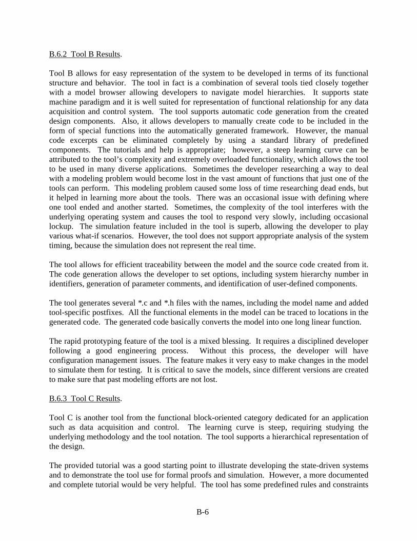
B.6.2 Tool B Results. Tool B allows for easy representation of the system to be developed in terms of its functional structure and behavior. The tool in fact is a combination of several tools tied closely together with a model browser allowing developers to navigate model hierarchies. It supports state machine paradigm and it is well suited for representation of functional relationship for any data acquisition and control system. The tool supports automatic code generation from the created design components. Also, it allows developers to manually create code to be included in the form of special functions into the automatically generated framework. However, the manual code excerpts can be eliminated completely by using a standard library of predefined components. The tutorials and help is appropriate; however, a steep learning curve can be attributed to the tool’s complexity and extremely overloaded functionality, which allows the tool to be used in many diverse applications. Sometimes the developer researching a way to deal with a modeling problem would become lost in the vast amount of functions that just one of the tools can perform. This modeling problem caused some loss of time researching dead ends, but it helped in learning more about the tools. There was an occasional issue with defining where one tool ended and another started. Sometimes, the complexity of the tool interferes with the underlying operating system and causes the tool to respond very slowly, including occasional lockup. The simulation feature included in the tool is superb, allowing the developer to play various what-if scenarios. However, the tool does not support appropriate analysis of the system timing, because the simulation does not represent the real time. The tool allows for efficient traceability between the model and the source code created from it. The code generation allows the developer to set options, including system hierarchy number in identifiers, generation of parameter comments, and identification of user-defined components. The tool generates several *.c and *.h files with the names, including the model name and added tool-specific postfixes. All the functional elements in the model can be traced to locations in the generated code. The generated code basically converts the model into one long linear function. The rapid prototyping feature of the tool is a mixed blessing. It requires a disciplined developer following a good engineering process. Without this process, the developer will have configuration management issues. The feature makes it very easy to make changes in the model to simulate them for testing. It is critical to save the models, since different versions are created to make sure that past modeling efforts are not lost. B.6.3 Tool C Results. Tool C is another tool from the functional block-oriented category dedicated for an application such as data acquisition and control. The learning curve is steep, requiring studying the underlying methodology and the tool notation. The tool supports a hierarchical representation of the design. The provided tutorial was a good starting point to illustrate developing the state-driven systems and to demonstrate the tool use for formal proofs and simulation. However, a more documented and complete tutorial would be very helpful. The tool has some predefined rules and constraints
B-6

that are not well documented. The developer created a few small, self-defined components and went through manual trials, resulting in a few run-time errors. The tool has the capability of full automatic code generation directly from the design model artifacts. The generated error messages are not descriptive, which requires more developer time to figure out the location or the nature of the errors. The generated source code was fairly easy to read and fairly well documented to reflect traceability to the implemented components or modules. However, one of the drawbacks for the automatically generated code is that it refers to header files located at different paths in the system. During every new tool execution, the tool initialization file causes the remaining license count to be decremented. After properly terminating or closing the software, the license will be incremented back again by one. However, when the tool terminated unexpectedly due to run-time errors (which happened occasionally during the project), it will not increment the number of remaining licenses by one back again. This resulted in eventually exhausting the licenses permissions and wasted valuable project time. B.6.4 Tool D Results. The learning curve for tool D was steep due to marginal and inconsistent tutorial documentation. Once the learning process was complete, the actual building of the model was significantly short, since the tool supports the type of design required by the data acquisition and control systems. The created model could be verified by a visual inspection via special function depicting the relation between various model components. The code generation produces several warnings attributed to variables that were long removed from the model. The tool can automatically generate documentation for created models listing all I/Os. The simulation capability allows the design to be verified before code generation. The specifics of tool D, based on the modeling approach, prohibited using programming loops. Such an approach required the developer to use multiple nodes and several imported operations. The created design included manually written data-reading functions that were reused multiple times in the system. The total number lines of generated code exceeded 1800. The traceability was checked using the lowest model layers. Checking traceability was not an easy task since the tool automatically assigns variable names. However, there is an option to assign a name to variables locally, which could take additional development time and was probably not the intent of the tool designers. Difficulty of traceability was extended due to relatively limited readability of the generated code. The code generator, after intermediate translation, creates one large source file. The format of the code is of limited readability due to lack of indentation and continuous alignment. It takes a while to find where in the code a specific model component actually starts and ends. The tool allows the developer to add source code manually (using an Imported Operator) during modeling phases. However, if the developer did not pay attention, the code generator would overwrite the working file, thus destroying the laboriously, manually added code by the developer. If the functions were used only once in a model, it would not be difficult to trace. However, due to the nature of the design, the averaging functions were used several times in the system. Based
B-7

on this single experiment, it was determined that the traceability of the generated code elements to a specific design component is rather cumbersome and not feasible for safety-critical systems. B.6.5 Tool E Results. Tool E allows the developer to represent the project as a set of cooperating applications. The tool has a relatively steep learning curve with learning materials hard to find. The provided examples of completed designs provide a good starting point. However, the tool requires a reasonably good knowledge of the underlying design methodology and notation, which is not well known outside a limited community of developers. After the familiarization is complete, using the tool is rather straightforward. All definitions for class and methods must be entered manually. All code to define the methods also needs to be entered into a definition pane. This could be made much easier by using a word processing tool and pasting the final text into the pane. With methods, data, and exceptions all having different windows, it was easy to look at the design and see where each piece belongs. It also has drawbacks by forcing the user to frequently switch between windows. The tool code generator creates only the code framework. The developer must manually define all data, functions, and exceptions. The tool has an annoying text editor bug: when using the backspace key, it actually deletes the character in front of the cursor, rather than behind it. When looking at a design, it is very hard to tell if a certain module has a state diagram or not. Another frustrating feature was the save button. Only by opening the design and its state window can the developer determine if the state diagram is defined. The tool allows the developer to open multiple copies of the same design window. However, it does support design consistency by not allowing developers to make changes in any design window while another window is open. The comments entered in the design window do not propagate to the generated code. The tool help option is limited to a noninteractive window with a marginal message. Anytime text was entered into any of the fields, the save button had to be pressed before switching to another window or even another pane for the same component. There was no shortcut or autosave feature that could make this less noticeable. Due to the nature of code generated as a framework only, the tool provides an easy way to establish traceability between the model components and the target code. B.7 TOOL EFFORT ANALYSIS. Four of the five developers (using tools A through D) completed the project, including the collection of effort data. Due to external circumstances, the developer that used tool E failed to conclude the project and, thus, the completed effort data was not collected (i.e., tool E is not included in the analysis). Software development tools, including automatic code generator functionality, allow developers to focus on the higher level of abstraction rather than engaging in a mundane coding. The aggregate results are shown in tables B-1 and B-2. The developers using the personal software process underestimated the preparation process effort by about 35%. The average planned time was 58 hours versus the actual time of 78 hours. On the other hand, the developers planned, on
B-8
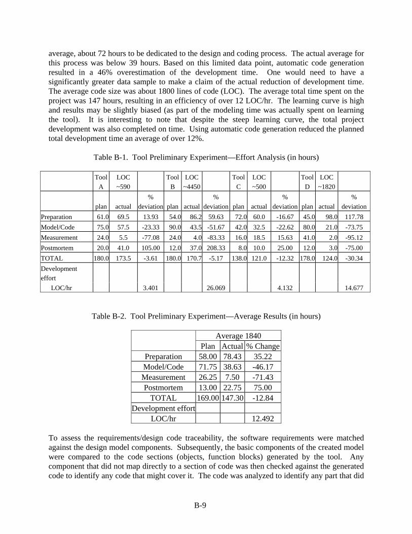
average, about 72 hours to be dedicated to the design and coding process. The actual average for this process was below 39 hours. Based on this limited data point, automatic code generation resulted in a 46% overestimation of the development time. One would need to have a significantly greater data sample to make a claim of the actual reduction of development time. The average code size was about 1800 lines of code (LOC). The average total time spent on the project was 147 hours, resulting in an efficiency of over 12 LOC/hr. The learning curve is high and results may be slightly biased (as part of the modeling time was actually spent on learning the tool). It is interesting to note that despite the steep learning curve, the total project development was also completed on time. Using automatic code generation reduced the planned total development time an average of over 12%.
Table B-1. Tool Preliminary Experiment—Effort Analysis (in hours)
Tool
A LOC ~590
Tool B
LOC ~4450
Tool C
LOC ~500
Tool D
LOC ~1820
plan actual %
deviation plan actual%
deviation plan actual %
deviation plan actual%
deviation Preparation 61.0 69.5 13.93 54.0 86.2 59.63 72.0 60.0 -16.67 45.0 98.0 117.78 Model/Code 75.0 57.5 -23.33 90.0 43.5 -51.67 42.0 32.5 -22.62 80.0 21.0 -73.75 Measurement 24.0 5.5 -77.08 24.0 4.0 -83.33 16.0 18.5 15.63 41.0 2.0 -95.12 Postmortem 20.0 41.0 105.00 12.0 37.0 208.33 8.0 10.0 25.00 12.0 3.0 -75.00 TOTAL 180.0 173.5 -3.61 180.0 170.7 -5.17 138.0 121.0 -12.32 178.0 124.0 -30.34 Development effort LOC/hr 3.401 26.069 4.132 14.677
Table B-2. Tool Preliminary Experiment—Average Results (in hours)
Average 1840 Plan Actual % Change
Preparation 58.00 78.43 35.22 Model/Code 71.75 38.63 -46.17 Measurement 26.25 7.50 -71.43 Postmortem 13.00 22.75 75.00
TOTAL 169.00 147.30 -12.84 Development effort
LOC/hr 12.492 To assess the requirements/design code traceability, the software requirements were matched against the design model components. Subsequently, the basic components of the created model were compared to the code sections (objects, function blocks) generated by the tool. Any component that did not map directly to a section of code was then checked against the generated code to identify any code that might cover it. The code was analyzed to identify any part that did
B-9

not relate to a specific model component, and if possible, its purpose was recorded. This analysis is to identify the purpose of any nontraceable function or code. The analysis shows that the traceability between design and the generated code is very much tool-dependent. B.8 PRELIMINARY EXPERIMENT CONCLUSIONS. The traceability between the model and code has been deemed the important criterion reflecting the tool deterministic behavior constituting the base for potential tool qualification. Due to the nature of the experiment, there was slight confusion regarding how traceability was to be measured. The provided script describes a process of decomposing the model developed within the tool into basic components and then mapping them into the code items generated by the tool from the model. Any model components and code that does not map is recorded. Initially, the traceability data were recorded in various ways, and they were not consistent with each other. In the future, experimentation logs need to be defined in which the developers can record their traceability data in a more uniform way. Also, there was no direct requirement for collecting quantified data, such as lines of code, so that the different tools could be compared to each other. Additional logs may need to be added in future experiments to capture this data. One major problem encountered during the initial experiment was with the tools’ licenses. This caused delays for some developers because their tool’s license had or would soon expire. One of the developers who originally selected tool A had license problems (license expired about 5 months before the project’s start) and had to switch tools with another developer. The license issue took about 7 weeks to resolve, but was ready for another developer who started the project later. Licenses of the tools to be used in research projects need to be checked and updated, if necessary, before the project’s launch date. In future projects, all license issues need to be resolved in advance. Traceability of code to model varied between the models. Both tools A and B made tracing code to models easy with various built-in features. In tool A, the code generated is well organized with comments, which makes it easier for anyone to read the code and trace it to the model. Apart from traceability, the tool maintains referential integrity between its components, which enforces the overall model consistency. One of the biggest advantages with tool B is with traceability between the models developed and the code generated from them. Tool B, in its options, allows the developer to decide the level of traceability by using options such as generate comments, force generation of parameter comments, and include system hierarchy number in identifiers. In one of the generated .h files, there is a comment listing a hierarchy of the model and corresponding system numbers. Using the system numbers from the hierarchy, each modeled function in the source code is labeled with the location in the model that the code was generated from. Comments in the code also identify any user-coded function. This allows for anyone to easily read the code and know where it came from in the model and to compare generated code to modeled function. Checking traceability was not easy for tool C, because of automatically assigned variable names. However, there was an option to assign names to variables locally. This action would take a lot of time, if all variables were locally assigned. This project had a lot of data flowing between the models, creating difficulty in the traceability of the assigned variables, and it was not easy to
B-10

read and analyze the generated codes. Tool C generated the codes into one file. The format of the codes was not easy to read because all codes were right aligned and not separated by a function by using spaces or tabs. It took a while to find where a model actually started and ended in the code. Also, tool C allowed the developer to import manually produced source code from an outside file during the modeling processes. It was very inconvenient to add source code after all code was generated. If the developer did not pay attention, the software would overwrite the working file (containing manual code) with a new template file. Overall, this preliminary experiment was an excellent experience to learn about software development tools, develop an evaluation infrastructure, and prepare for a more advanced tool metaevaluation-controlled experiment. Among the lessons learned, it was established that the process scripts needed to be updated. For the controlled experiment, improvements were implemented to have more uniform data logs to allow for easier analysis of results. Additionally, more quantified data for tool-to-tool comparison, qualitative (questionnaire), as well as quantitative (time and code data) was implemented.
B-11/B-12

APPENDIX C—CONTROLLED EXPERIMENT
The controlled experiment objective was a more detailed metaevaluation of the selected tools representing the type of tools under consideration: software design tools with automatic code generation capability. The selected sample included six tools from both the structural (object-oriented) and functional (block-oriented) categories. Tools L, M, and N are object-oriented, tools P and Q are block-oriented, and tool O crosses the boundary of the two categories. Four of the tools used in the preliminary experiment (listed in appendix B as tools A, B, C, D, and E) were used again for this controlled experiment. The following is the tool equivalency: A = L, C = Q, D = P, and E = M. Tool B was used only in the preliminary experiment, and tools N and O were used only in the controlled experiment. The developers were 14 graduate software engineering students familiar with software development methodologies, software processes, and real-time design concepts. Two or three developers, who shared the initial training and the final reporting, were assigned six tools. However, each of them developed the model and implemented code as an individual assignment. C.1 PURPOSE, SCOPE, AND DESCRIPTION OF THE EXPERIMENT. Each developer’s task included learning to use the tool and subsequently developing a simple design model and using the automatic code generation capabilities of the tool to generate the code for that model. The tool familiarization included developing a small demonstration application as a capstone for the learning phase. It is important to note that each developer was assigned to a tool with which they had no prior experience. Also, as in the preliminary experiment, the criterion under evaluation was traceability. This experiment also focused more on the learning aspect of using the tool and the support and documentation provided by the tool vendors. The experiment consisted of two models. The first model, a simple hair dryer simulator, was used during the learning phase of the experiment to facilitate the learning and constitute a capstone for familiarization with the methodology, tool, and the operating environment. The activities included reading documentation and materials about modeling methodology, experimenting with tool demonstrations, running tutorials, etc. The second system, a simple microwave oven software simulator, was used for the actual design and data collection. C.2 CONTROLLED EXPERIMENTS REQUIREMENTS. C.2.1 First Model Requirements. The first model, a hair dryer simulator, was defined by the following four requirements: • The system shall allow user to select motor speed (off, low, or high). • The system shall apply power to motor depending on the selected speed setting.
C-1

• The system shall cycle the heater (30 seconds on and 30 seconds off) when in low- and high-speed modes.
• The system display shall show the selected speed, heater status, and the countdown
time when the heater is on. C.2.2 Second Model Requirements. The second model, a microwave oven simulator, was defined by the following ten requirements:
• The oven shall allow user to set the cooking time in minutes and seconds (from default
00:00 to 59:59). • The oven shall allow user to set the power level (range from default 1 to 5) • The start of cooking shall initiate on explicit user request. • When the cooking starts, the oven shall turn on the light and the rotisserie motor for the
specified time period. • When the cooking starts, the oven shall cycle the microwave emitter on and off: a
power level of 5 means that the emitter is on all the time, a power level of 1 means that the emitter is on only 1/5 of the time.
• The oven shall display the remaining time of the cooking and the power level. • When the time period expires, the audible sound shall be generated and the light, motor,
and emitter shall be turned off. • The oven shall turn on the emitter and the motor only when the door is closed. • The oven shall turn on the light always when the door is open. • The oven shall allow the user to reset at any time (to the default values)
Suggested Interface:
• Inputs: TIME, POWER, START, RESET, 0-9, DOOR • Outputs: TIME, POWER, SOUND, LIGHT, MOTOR, EMITTER An additional nonfunctional constraint was to generate resulting C code. However, due to a misunderstanding of this requirement, one of the teams (assigned tool N) used the tool in a configuration producing C++ code instead.
C-2
C.3 THE DEVELOPMENT AND DATA COLLECTION PROCESS. A process script presented below was given to each developer. The script which included the four top-level tasks: (1) preparation, (2) model creation and code generation, (3) measurement, and (4) postmortem. This script is a refinement of the one used in the preliminary experiment, based on feedback from the participants. An overview of the script tasks is provided in the following sections. C.3.1 Preparation. • Creation of Personal Software Process (PSP) estimates of time and size for the project.
• Tool selection and becoming familiar with the project requirements.
• Learning to use the tool and identifying available resources that can be used during development.
• The development of the demonstration hair dryer model as a learning aid.
C.3.2 Model Creation and Code Generation. • The microwave oven model was created according to the specified requirements. • Each developer manually verified that all requirements were covered in the model. If the
tool provided verification capabilities, they were to be used if possible. • The code generation capabilities of the tool were then used to generate C code for the
model. C.3.3 Measurement. • Decomposition of the design model, which was then analyzed for traceability. • Decomposition and traceability to the model. • Decomposition and traceability to the requirements. • Identification of code that did not have a representation in the model. C.3.4 Postmortem. • Completion and analysis of PSP data. • Assessment of the tool’s conformance to traceability. • Compilation of each developer’s individual data into a joint report summarizing their
findings.
C-3

C.4 METHODS OF EVALUATION. Each developer was required to keep track of engineering observations during the course of the experiment to evaluate strengths and weaknesses of the tool, the process used, and other related elements. Developers were also required to record the time spent during each process to evaluate the effort required to develop a system while using the tool (see the tables in this appendix). The method employed in the initial experiment of decomposing the design models into their basic components was again used in this experiment. The first questionnaire addressed the documentation, manuals, and support of the tool under evaluation. The second questionnaire addressed the code generation capabilities of the tool. The application of each of these methods is described in the process script used for the experiment. C.5 CONTROLLED EXPERIMENT RESULTS. The results of the controlled experiment are divided into seven sections, with the first six describing each tool and the seventh addressing general observations from the experiment. Individual tool results are organized as follows: • Size and Effort: The number of lines of code (LOC) generated by the tool from the user-
designed experiment model (microwave oven model only). The time spent in the experiment for each process, the overall time spent by each developer, and an average of each measure.
• Developer subjective assessment (on a scale of 1-5) extracted from questionnaires with
the results grouped into the following four categories:
− Tutorial (Tool Questionnaire: Q2 – Q4) − User manuals and reference (Tool Questionnaire: Q5 – Q7) − Readability (Automatic Code Generation Questionnaire: Q1 – Q3) − Functionality (Automatic Code Generation Questionnaire: Q4 – Q6).
Note: Q1, Q8, and Q13 of the Tool Questionnaire and Q7 of the Automatic Code Generation Questionnaire were not included in the tables—analysis showed that they did not provide useful information.
• Engineering Observations • Traceability • Questionnaire Comments Note: The presented results are based on rather small observation sample. As such, the results give only an approximate assessment of the tool and do not have any statistical significance.
C-4

C.5.1 Tool L Results. Tool L is used for designing and developing object-oriented, real-time systems. The supported methodology is the unified modeling language (UML). Tool L uses extensions to UML that are necessary to capture real-time aspects. The basic UML concepts used for modeling are use case diagrams and class diagrams. The tool supports a number of standard UML diagrams: activity, object collaboration, object sequence, state, constraint, system architecture, table relationship, general graphics, and text. The extensions that are critical to model real-time systems are Timing, Concurrency, and Hardware and Software partitioning. The effort expended on tool L is shown in table C-1.
Table C-1. Tool L Effort
Tool L/LOC Developed LOC 339 LOC 386 LOC 291 Process Average (hr) Developer 1 (hr) Developer 2 (hr) Preparation 14.28 19.80 8.75 Model/Code 17.75 28.50 7.00 Measurement 4.00 1.50 6.50 Postmortem 10.25 7.50 13.00 Total 46.28 57.30 35.25
The tool allows for explicit timing information to be added to a sequence diagram (where standard UML only allows for notes). Collaboration diagram is expanded upon, the result is the concurrency diagram, which shows several aspects of the tasking and communication structure in the system. The tool does not verify the design correctness and does not have any simulation capabilities. The code generated by the tool contained only the includes for libraries, global variables, functions, and structs. The developer needs to manually enter the program for the behavioral part of the project. It should be noted that due to the need to manually code the detail of the functions in the design model during the code generation process, the detail of the design produced by developer 1 was much greater than developer 2, which led to the differences in development time during the model/code process. The tool L assessment is provided in table C-2.
Table C-2. Tool L Assessment
Topic Average Developer 1 Developer 2 Tutorial 3.17 3.00 3.33 User manuals and reference 2.83 3.33 2.33 Readability 3.17 3.00 3.33 Functionality 3.50 3.00 4.00 Total rating 3.17 3.08 3.25
Developer Assessment 0/Low to 5/High.
C-5

C.5.1.1 Engineering Observations. The tutorials were complete and concise—allowing for a seamless transition into the project. The user interface was very intuitive as each had a complete set of menus and buttons familiar to Windows users. The menus were organized so that the tools and utilities were easy to locate and use. Modeling was intuitive as well. Various tabs and trees were defined where each item was located, such as diagrams and data types. When creating a diagram, one could use an actor or element that was created for another diagram; this was as expected and worked without errors. Both developers 1 and 2 felt that the tool was very intuitive. The resources available were sufficient enough to generate the models efficiently and to produce a working application. The general conclusion from both developers was that the tool would be useful for any software project. The modeling and code generation were less time-consuming than initially anticipated and, therefore, reduced the amount of time needed for the development.
C.5.1.2 Traceability.
The developers demonstrated traceability by tracing the requirements into the modeled objects’ variables and operations. This showed how their design met all the requirements. The developers then traced the modeled design to the tool-generated code. This was made easy by the tool, which used the same variable and operation names for the generated C code as was in the developers’ modeled designs. Excluding a few code elements (i.e., dummy variables) that were not traceable to any design element, the generated code was fully traceable to the design elements. The exceptions, nDummy variables, were automatically added to any class within the model and in turn would be generated within the source code. C.5.1.3 Questionnaire Comments. The tool received favorable comments for its intuitive interface and its ability to generate documentation for user models. The ability to run concurrent models with the synchronizer, keeping them and their associated documentation up to date, was also listed as a useful feature. A simulation feature and a more complete user document of the diagrams and their related syntax were noted as desirable for future releases of the tool. Both developers stated that the tool was suitable for use in small- to medium-scale projects (>5000 LOC), noting that the complexity of the diagrams may become a problem for large-scale projects. With exceptions of the following, the developers rated this tool as high in quality. • Constraints placed on diagrams are not documented. The specific sequence for creating
any diagram was not documented and, therefore, was not an easy feature to use. An example is the sequence diagram: a description of the message or activity must be entered before the message or activity. There is no clear means of how this is to be done, and it is not specified in the tutorial or context help.
• Automatic code generation does not actually produce the body of the functions. The
developer must manually enter the code.
C-6

C.5.2 Tool M Results. Tool M is an object-oriented design tool, using a particular object-oriented methodology. The particular methodology supports a fully integrated real-time model, as well as other high-level software engineering concepts, such as generality and exception handling. It employs simple notations combining the use of a light graphical notation and an exhaustive textual structure that attempts to bring a compromise to handling architectural complexity while providing a framework for documentation and coding. The effort expended on tool M is shown in table C-3.
Table C-3. Tool M Effort
Tool M/LOC Developed 159 159 159 Process Average (hr) Developer 1 (hr) Developer 2 (hr)Preparation 50.13 74.28 25.98 Model/Code 25.50 41.00 10.00 Measurement 8.25 12.00 4.50 Postmortem 14.17 25.00 3.33 Total 98.05 152.28 43.81
The data collected show marked differences between the developers performing the experiment, in particular, time spent on the project. The difference could be attributed to one developer getting help from a colleague who had prior familiarity with the tool (the experiment could not be fully controlled due to the classroom requirements). Overall, the number of lines of generated code does not differ greatly, noting that the design models for the two systems are similar. The tool M assessment is provided in table C-4.
Table C-4. Tool M Assessment
Topic Average Developer 1 Developer 2 Tutorial 0.34 0.67 0.00 User manuals and reference 2.67 2.33 3.00 Readability 2.67 1.67 3.67 Functionality 3.00 2.33 3.67 Total rating 2.17 1.75 2.59
Developer Assessment (0/Low to 5/High) C.5.2.1 Engineering Observations. Learning to use the tool and its methodology accounted for a large portion of the project time. Use of this tool assumes previous knowledge of tool methodology, with no tutorial and incomplete online documentation. There was also a lack of updated documentation pending a new release, which made working through a simple example difficult. In addition, the tool was not very intuitive to use, and the user interface tended to get confusing, since each feature has its own window and windows were not easily distinguishable from each other. Model verification
C-7

was a difficult task due to the methodology employed, and the output messages were cryptic and difficult to understand.
The tool does not generate production code, but rather, the structure of the code. All the required “includes” for the header files are generated. Translation from an object-oriented design supported by the tool to straightforward procedural C code was also difficult, since many object-oriented techniques and methods were not supported in the translation. C.5.2.2 Traceability.
The developers demonstrated traceability by tracing the requirements into their model components (modeled objects and their states). This showed how their design met all the requirements. The developers then traced their modeled components to the tool-generated code. The tool generated *.c and *.h files for each object in the model. The modeled states are included in their object’s *.c and *.h files. Functionality of one additional *.h file created during code generation was not known to the developers. C.5.2.3 Questionnaire Comments. The tool was criticized for its lack of tutorials and marginal documentation. Both developers noted that the time spent in learning to use the tool could have been greatly decreased had sufficient materials been available. The tool received marginal recommendations from both developers for use in small- and large-scale systems. However, opinions differed as one developer favored large-scale systems and the other favored small-scale systems for development with this tool. Tutorials and more complete documentation were recommended as favorable inclusions in future possible versions. C.5.3 Tool N. Tool N supports the UML methodology. The diagrams available in the tool include object model and class diagrams, sequence diagrams, state charts, use case diagrams, activity diagrams, collaboration diagrams, component diagrams, and deployment diagrams. The tool uses a model/code associativity, which means that changes made to the model will automatically introduce change in the code and vice versa. It also uses a real-time object execution framework to hide many of the deployment details. The tool is available in different packages with different levels of functionality. The version used for this experiment was the one with the most functionality available. The effort expended on tool N is shown is table C-5.
C-8
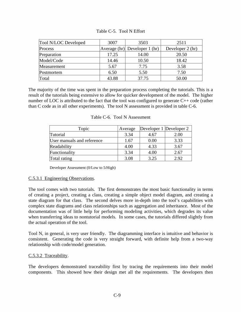
Table C-5. Tool N Effort
Tool N/LOC Developed 3007 3503 2511 Process Average (hr) Developer 1 (hr) Developer 2 (hr) Preparation 17.25 14.00 20.50 Model/Code 14.46 10.50 18.42 Measurement 5.67 7.75 3.58 Postmortem 6.50 5.50 7.50 Total 43.88 37.75 50.00
The majority of the time was spent in the preparation process completing the tutorials. This is a result of the tutorials being extensive to allow for quicker development of the model. The higher number of LOC is attributed to the fact that the tool was configured to generate C++ code (rather than C code as in all other experiments). The tool N assessment is provided in table C-6.
Table C-6. Tool N Assessment
Topic Average Developer 1 Developer 2 Tutorial 3.34 4.67 2.00 User manuals and reference 1.67 0.00 3.33 Readability 4.00 4.33 3.67 Functionality 3.34 4.00 2.67 Total rating 3.08 3.25 2.92
Developer Assessment (0/Low to 5/High) C.5.3.1 Engineering Observations. The tool comes with two tutorials. The first demonstrates the most basic functionality in terms of creating a project, creating a class, creating a simple object model diagram, and creating a state diagram for that class. The second delves more in-depth into the tool’s capabilities with complex state diagrams and class relationships such as aggregation and inheritance. Most of the documentation was of little help for performing modeling activities, which degrades its value when transferring ideas to nontutorial models. In some cases, the tutorials differed slightly from the actual operation of the tool. Tool N, in general, is very user friendly. The diagramming interface is intuitive and behavior is consistent. Generating the code is very straight forward, with definite help from a two-way relationship with code/model generation. C.5.3.2 Traceability.
The developers demonstrated traceability first by tracing the requirements into their model components. This showed how their design met all the requirements. The developers then
C-9

traced the modeled design to the tool-generated code. The tool generated .cpp and .h files for each modeled component plus additional default .cpp and .h files. C.5.3.3 Questionnaire Comments.
Both developers highly recommended the tool for use in small- and large-scale systems. Both developers agreed that they would use the tool in future developments. A more comprehensive tutorial and a simulation feature were recommended as additions to future possible versions. C.5.4 Tool O. Tool O is a model-based development tool based on UML 2.0 that targets real-time and embedded software. Its functionality includes automatic code generation of application software, visual simulation, and verification of real-time behavior. It supports the object model group’s Model-Driven Architecture software development approach. It has an extensive amount of features and integrates with other products to add requirements traceability and configuration management. The effort expended on tool O is shown in table C-7.
Table C-7. Tool O Effort
Tool O/LOC Developed 11227 11227 11227 Process Average (hr) Developer 1 (hr) Developer 2 (hr)Preparation 9.00 12.00 6.00 Model/Code 16.53 17.55 15.50 Measurement 3.00 3.00 3.00 Postmortem 7.00 10.50 3.50 Total 35.53 43.05 28.00
The model/code process of development was the most time-consuming, due to using the UML 2.0 notation and the excessive amount of code generated by the tool for a relatively small application. Tool O assessment is provided in table C-8.
Table C-8. Tool O Assessment
Topic Average Developer 1 Developer 2 Tutorial 2.33 2.33 2.33 User manuals and reference 2.67 3.00 2.33 Readability 2.00 3.00 1.00 Functionality 1.67 2.33 1.00 Total rating 2.17 2.67 1.67 Developer Assessment (0/Low to 5/High)
C-10

C.5.4.1 Engineering Observations. Learning how to use this tool was difficult due to inadequate and incomplete learning materials. The tutorial covered only basic functionality, and the other learning materials were not useful in learning how to use the tool.
The tool is designed for large-scale development projects. The case study developed for this evaluation generated a huge number of diagrams and an excessive amount of code for such a small application. The tool appears to be useful in large-scale projects and overly difficult for small projects, such as the case study developed for this evaluation. The developers maintained that it would have been faster, in this case, to design and code the application by hand than to use the tool. Code generation seems like a great feature, but the excessive amount of generated code (over 11 thousand LOC) could cause problems in real-time systems. Code generation was also very difficult to complete. Several totally undocumented steps must be taken to successfully generate C code. Syntax errors appeared in the generated code, and any user interaction functionality had to be laboriously implemented by hand. Also, the tool seems to be very limiting in the options and methods developers must use if code is to be generated from the models.
C.5.4.2 Traceability.
The developers demonstrated traceability by tracing the requirements into their model components. This showed how their design met all the requirements. The developers then traced their modeled components to the tool-generated code. The tool generated two files: (1) modelName.c, which represents the entire system and (2) modelName_env.c, which handles system interaction with user or external environment. The developers stated that due to the volume of code generated and the cryptic nature of all the identifiers, function names, code structure, etc., it has been impossible to map the modeling elements to code. They also tried to use the locate in code feature provided by the tool, but it did not work. C.5.4.3 Questionnaire Comments. The tool was recommended highly for large-scale systems, but poorly for small-scale systems. The supporting materials were criticized for poor coverage of tool use. More complete documentation and better technical support were recommended for future possible versions. C.5.5 Tool P. Tool P is a block-oriented software development tool, which allows the user to model a system design using a synchronized data flow model with building blocks that should be familiar to those with experience in digital circuit design. The model is converted to a synchronous language and then C source code is generated. It provides features such as model editor, simulator, C, and Ada code generator, report generator, automatic testing, safe-state machine with concurrency support and also the ability to import models generated in other specific tools.
C-11

The effort expended on tool P is shown in table C-9, and the tool P assessment is shown in table C-10.
Table C-9. Tool P Effort Tool P/LOC Developed 482 734 228 484 Process Average (hr) Developer 1 (hr) Developer 2 (hr) Developer 3 (hr) Preparation 12.68 14.85 10.60 12.58 Model/Code 7.57 8.50 6.08 8.13 Measurement 3.32 2.50 5.42 2.03 Postmortem 4.97 8.00 3.70 3.20 Total 28.53 33.85 25.80 25.94
Table C-10. Tool P Assessment
Topic Average Developer 1 Developer 2 Developer 3 Tutorial 1.67 1.67 1.67 1.67 User manuals and reference 3.00 2.67 2.67 3.67 Readability 3.44 2.67 3.33 4.33 Functionality 2.22 2.33 3.33 1.00 Total rating 2.58 2.34 2.75 2.67
Developer Assessment (0/Low to 5/High)
C.5.5.1 Engineering Observations. The tutorial for Tool P is not well organized and is not continuous between chapters. The tool is targeted to developers with a control and electrical engineering background, not software engineers. The tool allows basic components to be built and integrated into a more complex design. The modeling tool allows subcomponents to be built, reused, and integrated into more complex and larger components. The whole system can be built using these building blocks. The tool’s support for state machines does not seem to work. The state machine is either not compiling at all, or in some instances, the application crashes while attempting it. It should be noted that the crashing scenario also occurred with an earlier version of the tool. The source code generated by the three designs ranged from 200 to 700 LOC. The generated code structure is very well organized. Each node and component is implemented as a separate source file and header. This aids traceability, since each model component can be directly mapped to the source code.
C-12

C.5.5.2 Traceability.
The developers demonstrated traceability by tracing the requirements into their model nodes. This showed how their design met all the requirements. The developers then traced their models to the tool-generated code. The tool generated *.c and *.h files for each node in the model. Three additional files were generated, which were named after the highest hierarchical node: nodeName_extern.h, nodeName_global.c, and nodeName_main.h. These three files defined all needed standard file, the global and constant values used in the model. C.5.5.3 Questionnaire Comments. The developers commented on the need for a better help mechanism within the tool. The simulation and model-checking capabilities were most favored by the developers, and the tool was recommended for small- and large-scale developments. Better tutorials, documentation, and support were recommended for inclusion in future releases. C.5.6 Tool Q. Tool Q is a functional block-oriented tool using functional components in a form of graphical symbols showing their function. The body of components is either described in internal synchronous language or the component itself is a diagram, thus making a hierarchical description of the system. Components are stored in libraries that can be created and enriched at will, which encourages reuse of components, thereby saving valuable development time. To describe each component, the user chooses from different styles: data flow style, state machines, truth tables, etc. Components are then interfaced together in a data flow fashion. The effort expended on tool Q is provided in table C-11, and the tool Q assessment is shown in table C-12.
Table C-11. Tool Q Effort Tool Q/LOC Developed 1293 1430 1430 1018 Process Average (hr) Developer 1 (hr) Developer 2 (hr) Developer 3 (hr)Preparation 8.83 4.50 9.00 13.00 Model/Code 5.95 8.75 6.00 3.10 Measurement 4.17 0.50 5.00 7.00 Postmortem 3.33 4.00 4.00 2.00 Total 22.28 17.75 24.00 25.10
C-13

Table C-12. Tool Q Assessment
Topic Average Developer 1 Developer 2 Developer 3 Tutorial 2.11 1.67 2.67 2.00 User manuals and reference 3.00 3.00 2.67 3.33 Readability 1.33 1.33 1.00 1.67 Functionality 1.78 2.67 1.00 1.67 Total rating 2.06 2.17 1.84 2.17
Developer Assessment (0/Low to 5/High) C.5.6.1 Engineering Observations. The user interface was not very intuitive. A heavy burden was placed on the developer to know what can and cannot be done with the models. This was especially true when trying to determine how to create a variable to hold data for a simple counter. The documentation did not provide a solution, and it was only through repeated attempts at compiling that a solution arose. The two tutorials that came with the tool were somewhat helpful. Both introduced functionality that came into play later on in the project. However, one tutorial did have a few errors, and both did not provide adequate descriptions of the steps in the development process. One good feature was the simulation capability of the tool. It was easy to execute the model in real time and observe its exact behavior. Another plus was the formal prover—a functionality of formally checking the design model for consistency. It was introduced in the tutorials and was a great asset, being automatically invoked before every compile and checking the model for any inconsistencies. The tool generates code only if the model checks out. C.5.6.2 Traceability. The developers demonstrated traceability by tracing the requirements into their model components. This showed how their design met all the requirements. The developers then tried to trace their models to the tool-generated code. The developers all stated that it was impossible to tell where in the code the model components are actually located. This was primarily due to the amount of code and the naming convention used in the generated code. C.5.6.3 Questionnaire Comments. The developers noted that the reliability of the tool was a problem, it crashed multiple times during their development activities. The lack of sufficient, complete documentation was also noted as a problem. The tool was not highly recommended by the developers for use in small- or large-scale developments. Better documentation, technical support, and tutorials were all recommended for future possible versions. The issue of reliability was also noted as a consideration for future versions.
C-14

C.6 GENERAL COMMENTS. From the perspective of the development paradigms used for these tools, i.e., object-oriented and block-oriented, the developers’ effort seems to be related to the paradigm used. Tools L, M, and N are all based on object-oriented paradigm and, with the exception of tool M, the time spent in development is very similar. The difference in the effort while using tool M was attributed to the learning curve associated with the particular object-oriented methodology used by the tool, slightly different than the more familiar UML. For the functional block-oriented tools, O, P, and Q, the effort is also similar across the processes and, on average, is less than the object-oriented tools. Tables C-13 and C-14 show the productivity resulting from the developers effort and the size of code generated by the tool. It is important to remember that the tools automatically generated the code, with little or no manual coding by the developers.
Table C-13. Tool-Controlled Experiment—Effort Analysis, Tools L-N (in hours)
Tool L 339 Tool M 159 Tool N 3007
LOC Plan Actual % Change Plan Actual % Change Plan Actual % Change Preparation 17.5 14.3 -18.40 32.3 50.1 55.44 16.8 17.3 2.99 Model/Code 9.3 17.8 91.89 19.5 25.5 30.77 15.5 14.5 -6.71 Measurement 7.0 4.0 -42.86 8.0 8.3 3.13 9.0 5.7 -37.00 Postmortem 8.0 10.3 28.13 13.5 14.2 4.96 7.5 6.5 -13.33 TOTAL 41.8 46.3 10.85 73.3 98.1 33.86 48.8 43.9 -9.99 Dev Effort LOC/hr 7.325 1.622 68.528
Table C-14. Tool-Controlled Experiment—Effort Analysis, Tools O-Q (in hours)
Tool O 11,227 Tool P 482 Tool Q 1,293
LOC Plan Actual % Change Plan Actual % Change Plan Actual % Change Preparation 4.0 9.0 125.00 12.3 12.7 3.09 8.4 8.8 4.87 Model/Code 11.0 16.5 50.27 6.3 7.6 20.16 2.8 6.0 113.26 Measurement 4.0 3.0 -25.00 4.3 3.3 -22.79 4.7 4.2 -10.71 Postmortem 5.0 7.0 40.00 4.7 5.0 6.42 2.7 3.3 24.72 TOTAL 24.0 35.5 48.04 27.6 28.5 3.52 18.6 22.3 20.11
Dev Effort LOC/hr 315.986 16.889 58.034
Table C-15 reflects the aggregate results related to efficiency in terms of development effort. Tables C-16 and C-17 contain the outcome of qualitative assessment of tools in the controlled experiment in terms of results of the questionnaires.
C-15

Table C-15. Tool-Controlled Experiment—Average Results (in hours)
Average 2751 LOC Plan Actual % Change
Preparation 15.20 18.70 22.97 Model/Code 10.72 14.63 36.40 Measurement 6.16 4.74 -23.15 Postmortem 6.89 7.70 11.80 TOTAL 38.98 45.76 17.40
Dev Effort LOC/hr 60.122
Table C-16. Tool-Controlled Experiment—Tool and ACG Questionnaire Results (scale 0-5)
Result Categories Tool L Tool M Tool N Tool O Tool P Tool Q
Tutorial 3.2 0.3 3.3 2.3 1.7 2.1 User manuals and reference 2.8 2.7 1.7 2.7 3.0 3.0 Readability 3.2 2.7 4.0 2.0 3.4 1.3 Functionality 3.5 3.0 3.3 1.7 2.2 1.8 Average 3.2 2.2 3.1 2.2 2.6 2.1
Table C-17. Tool-Controlled Experiment—Average
Questionnaire Results (scale (0-5)
Result Categories AverageTutorial 2.16 User manuals and reference 2.64 Readability 2.77 Functionality 2.59 Average 2.54
C-16

C.7 TRACEABILITY TABLES. This section contains the traceability tables (C-18 through C-20) used in the controlled experiments.
Table C-18. Requirements Traceability Table
Requirement ID Model Components Comments
Table C-19. Model Traceability Table
Model
Components Code File Code Function Comments
Table C-20. Code Traceability Table
Code File Code Function Comments
C.8 DEVELOPERS LOGS. This section contains the developers logs used in the controlled experiments. (Figures C-1 through C-3). Individual Task Planning Template
Name Date Course Project
Plan Actual Phase Task (Activity) Date Hrs Date Hrs
Total
Figure C-1. Task Planning Log
C-17

Time Recording Log
Phase Date Start Int. Stop Delta Comments
Total min hours
Figure C-2. Time Log
Date Issue Description Cause
Cause Codes: User: if issue was caused by user’s inexperience with or lack of knowledge of tool. Tool: if issue was caused by a defect in or design of the development tool. System: if issue was caused by networking or operating system problems. Doc: if issue was caused by lack of or incomplete coverage of tool documents. Other: if issues cause is not covered by above code or is unknown.
Figure C-3. Engineering Observation Log
C-18

C.9 QUESTIONNAIRES. This section contains the questionnaires used in the controlled experiments.
TOOL ASSESSMENT QUESTIONNAIRE
Your name: Tool used: List of documentations available: (Both online and offline)
Scale Legend 0 Not Applicable; 1 Strongly Disagree; 2 Somewhat Disagree; 3 Neutral 4 Somewhat Agree; 5 Strongly Agree
TUTORIAL 1. After the completion of tutorial, I do refer to it often while working on the project. 0 1 2 3 4 5 2. The tutorial is well-structured and it is easy to follow. 0 1 2 3 4 5 3. I have learned all the basic essential skills from the tutorial, necessary to start exploring on my own. 0 1 2 3 4 5 4. In my opinion, I think the tutorial has accomplished balance of being easy-to-follow and also has covered the topics in sufficient depth. 0 1 2 3 4 5 USER MANUALS AND REFERENCE GUIDE 5. For those features that are not covered by the tutorial, I am able to get relevant information on their usages through the accompanied reference materials. 0 1 2 3 4 5 6. I do consider the reference manual a good source for information. For example: I do refer to it whenever I had questions about the tool rather than trust my own instinct or sources other than the reference materials. 0 1 2 3 4 5 1. I did encounter features that have not been covered by the tutorial or reference materials thoroughly, that forced
me to acquire help by different means. 0 1 2 3 4 5
2. An estimate number of times I have referred to the user manual, reference guide is: INTERACTIVE SUPPORT 9. What kind of alternative assistance have you sought when you are trying to use the tool? (Check all that applies) __ Colleague __ Faculty ___Library ___Internet 10. How many times have you contacted the technical support through the following means?
C-19

__ Phone __ Email 11. If you have used telephone to contact the tool vendor for support, how long was the waiting time until you are connected with the right technical staff to assist you? __ 0-15 minutes __ 16-30 minutes __over 1 hour __they hung up 12. If you have used Email to contact the tool vendor for support, how responsive was your inquiry? __ 1-2 days __ within one week __ longer than a week __never heard from them 13. If you have contact the tool vendor for support, do you find them knowledgeable? Did you get a good solution to the problem? 0 1 2 3 4 5 IMPRESSIONS ABOUT THE TOOL USE
1. What feature would I like to see in the next version of the tool?
2. Given a choice – would I use the tool for my next project?
3. Few things (if any) I like the most about the tool?
4. Few things (if any) I like the least about the tool?
5. Specific comments/observations:
C-20

AUTOMATIC CODE GENERATION QUESTIONNAIRE Check off the tool you used.
Rhapsody:_____ Artisan Real Time Studio:_____ TNI-Valiosys STOOD:_____ Esterel Technologies SCADE:_____ TNI-Valiosys Slidex:_____ Mathworks Simulink Real Time Workshop:_____
Scale Legend 0 Not Applicable; 1 Strongly Disagree; 2 Somewhat Disagree; 3 Neutral 4 Somewhat Agree; 5 Strongly Agree
The basic program structure generated by the code generator is excellent.
0 1 2 3 4 5 Comments:
The comments in the generated code help me to make sense of the code.
0 1 2 3 4 5 Comments:
The variable names and labels help me to follow the code’s functionality.
0 1 2 3 4 5 Comments:
The generated code was efficient in terms of the usage of things like functions, loops, recursive functions, etc.
0 1 2 3 4 5
Comments: The generated code allow making changes or additions (it was easy to make a change and one small change did not
involve changes to the entire program).
0 1 2 3 4 5 Comments:
The length of the code contributed to its functionality.
C-21

0 1 2 3 4 5
Comments:
The online help guides/menus were tailored enough to my needs.
0 1 2 3 4 5 Comments:
I would you recommend this code generator as a worthwhile tool over manual coding in large scale complex software systems.
0 1 2 3 4 5
Comments:
I would you recommend this code generator as a worthwhile tool over manual coding in small scale software systems?
0 1 2 3 4 5
Comments:
C-22

APPENDIX D—REAL-TIME DEVELOPMENT TOOLS—COMMERCIAL PRODUCTS The presented list of products, shown in tables D-1 through D-11, reflects the state of the commercially available software development tools at the time the research was conducted (2002-2004). Most of these tools that are available on the Internet have shortcomings that (1) include, indiscriminately, all categories of tools; (2) are out-of-date and provide links to tools/vendors that have long disappeared from the market; and (3) include links to new, but not industry-strength products with fancy user interfaces and marginal internals. The list is limited to the tools whose functionality matches the one selected to be the focus of this research: design tools with a code generation feature. The list has been compiled based on input from industry and research of the market via trade shows, literature, and direct inquiries. Except the most recent ones, the tools that are not available anymore due to the vendor closing or merging with another company are not included. However, since the software tool market is extremely volatile, it may happen that some of the presented contacts are out of date. Also, due to a rapid proliferation of small software companies, some tools may have not shown up in the search and, thus, are not listed. This appendix is for informational purposes only and does not constitute endorsement of any of the listed products. See tables D-1 through D-11 for software test descriptions.
D-1

Table D-1. Telelogic Tools
Developed By Tool Name Description
Telelogic http://www.telelogic.com/
Tau Developer ObjectGEODE
TAU Developer is a structural UML 2.0 based tool for the design and development of robust, advanced software components and applications. It allows visual simulation and verification of dynamic behavior. It automates the transition from design to implementation by generating executable software (in C, C++, or Java) from the design models. ObjectGEODE is a tool set dedicated to analysis, design, verification and validation through simulation, code generation, and testing of real-time and distributed applications. It supports a coherent integration of complementary object-oriented and real-time approaches based on the UML, SDL, and MSC, standards languages. ObjectGEODE provides graphical editors, simulator, a C code generator, and a design-level debugger.
UML = Unified modeling language SDL = Specification and description language MSC = Message sequence chart
Table D-2. LogIx Inc. Tools
Developed By Tool Name Description
i-Logix, Inc. http://www.ilogix.com/
Rhapsody Statemate
Rhapsody is a structural oriented design tool (UML) for system and software design, analysis, and modeling. It provides means for design-level verification of the behavior of the software. It supports code generation in C/C++/Java. Statemate is a design tool based on state charts concept. It supports design and validation of complex system-level products through a unique combination of graphic modeling, simulation, code generation, documentation generation, and test plan definition.
D-2

Table D-3. The Mathworks Tools
Developed By Tool Name Description
The MathWorks http://www.mathworks.com
MATLAB Simulink® Stateflow® Real-Time Workshop®
MATLAB is a tool for solving engineering and science problems using mathematical computation, analysis, visualization, and algorithm development. Together with other tool sets (such as Simulink and Stateflow), it becomes a platform for functional-oriented software design. Simulink is a platform for simulation and Model-Based Design of dynamic systems. It provides an interactive graphical environment and a customizable set of block libraries to design, simulate, implement, and test control, signal processing, communications, and other time-varying systems. Stateflow is an interactive design and simulation tool for event-driven systems. It provides the language elements required to describe complex logic. It is tightly integrated with MATLAB and Simulink, providing an environment for designing embedded systems that contain control, supervisory, and mode logic. Real-Time Workshop generates and executes stand-alone C code for developing and testing algorithms modeled in Simulink. The resulting code can be used for real-time applications, rapid prototyping, and hardware-in-the-loop testing while monitoring the generated code using Simulink blocks and built-in analysis capabilities. It allows developers to run and interact with the code outside the MATLAB/Simulink environment.
D-3

Table D-4. Estrel Technologies Tools
Developed By Tool Name Description
Esterel – Technologies http://www.esterel-technologies.com/
SCADE Esterel Studio
SCADE safety-critical application development environment used to develop embedded software optimized for the requirements of the automotive industry. It is a functional oriented design tool, which can perform simulation, formal proofing, and source code generation. Esterel Studio is a design environment, optimized for complex control-dominated IPs (such as DMA devices, protocols, cache controllers, I/O subsystems, etc.), dedicated at capturing formal design specifications, enabling formal verification of properties very early in the design process, and automating the production of synthesizable RTL (VHDL and Verilog), both for prototyping and production purposes.
DMA = Direct memory access IP =Internet protocol I/O = Input/Output VHDL = Very high-speed integrated circuit hardware descriptor language RTL = Register transfer level
Table D-5. Artisan Software Tools, Inc. Tools
Developed By Tool Name Description
ARTiSAN Software Tools, Inc. http://www.artisansw.com
Real-Time Studio
Real-Time Studio is a structural multiuser suite of development tools developed around the UML standard. It allows developers to capture software and system designs, verify system behavior, simulate the models, and generate code.
D-4

Table D-6. Rational/IBM Tools
Developed By Tool Name Description
Rational/IBM http://www.rational.com
Rose RT (became IBM Developer Suite)
Obiect-Oriented software development environment based on ObjecTime supporting UML architectural concepts.
Table D-7. Engenuity Technologies Tools
Developed By Tool Name Tool’s Description
ENGENUITY Technologies http://www.engenuitytech.com/
VAPS Suite VAPS is a software tool suite supporting human-machine interface development for rapid prototyping, designing, testing, and deployment. It enables the development of dynamic, interactive, real-time graphical HMIs for complex applications
HMI = Human-machine interface
Table D-8. TNI-Valiosys Tools
Developed By Tool Name Description
TNI-Valiosys http://www.tni-valiosys.com/ evolved into: Tni-Software http://www.tni-software.com/
Stood not supported Sildex not available, replaced by RT Build (no authentic code generation capability)
STOOD is a structural-oriented design tool based on the hierarchical object-oriented design methodology. It supports design verification, code generation, and document generation. Sildex is a functional-oriented design tool that uses an underlying formal notation, transparent to the user. It can perform simulation, formally verification of the model, and automatic code generation in Ada, C, and C++. RTBuild is Sildex replacement and seem to be related to ControlBuild CASE tool allows a global approach to application development from requirement through design (no code generation).
CASE = Computer-aided software engineering
D-5

Table D-9. Applied Dynamics International Tools
Developed By Tool Name Description
Applied Dynamics International http://www.adi.com/
BEACON BEACON tools are block-oriented engineering analysis and code generation tools designed to generate safe, reliable code. It works with automatic unit test tool, which generates test vectors directly from diagrammatical requirement specifications.
Table D-10. National Instruments Tools
Developed By Tool Name Description
National Instruments http://www.ni.com/
MATRIXx MATRIXx is a software suite for model-based control design providing means for modeling and simulation of dynamic systems. It has code generation features for creating real-time embedded control software.
Table D-11. Honeywell Tools
Developed By Tool Name Tool’s Description
Honeywell http://www.htc.honeywell.com
MetaH DOME
MetaH is a language and tool set for developing real-time multiprocessor avionics system architectures. It allows a developer to describe the interfaces and selected properties of software and hardware components and then combine them into an integrated system. It provides tools for analyzing real-time schedulability, reliability, and partition integrity. No code generator available. DOME is a meta-CASE system suitable for building object-oriented software models (Coad-Yourdon, UML). It includes a graphical front-end, and a back-end language for generating code, analyses, and documentation.
D-6