Petroleum Infrastructure of Ireland. Petroleum infrastructure Irish Petroleum Industry Association.

ASSESSMENT OF THE PETROLEUM INDUSTRY
HAZARDOUS WASTE SOURCE REDUCTION
PLANNING EFFORTS
Doc. No. 536
California Environmental Protection Agency
Department of Toxic Substances Control
Office of Pollution Prevention andTechnology Development
June 1997
Pete Wilson, GovernorState of California
James M. Strock, SecretaryCalifornia Environmental Protection Agency
Jesse R. Huff, DirectorDepartment of Toxic Substances Control

ASSESSMENT OF THE PETROLEUM INDUSTRY HAZARDOUSWASTE SOURCE REDUCTION PLANNING EFFORTS
Prepared by Arvind Shah
California Environmental Protection AgencyDepartment of Toxic Substances Control
Office of Pollution Prevention and Technology Development
June 1997


This report was prepared by Arvind Shah under thedirection of Alan Ingham and Kim Wilhelm, Source ReductionUnit, Office of Pollution Prevention and TechnologyDevelopment.
ACKNOWLEDGEMENTS
The Department of Toxic Substances Control appreciatesthe efforts made by California’s petroleum industry toassist with the preparation of this report and to reducehazardous waste generation as discussed in industrydocuments prepared in response to the Hazardous Waste SourceReduction Management Review Act. In particular, we wouldlike to thank the following for the extra time andcooperation they provided: Gary Tietavainen, ARCO ProductsCompany, Annabelle Troin, Ultramar, Incorporated and HildingSpradlin, Tosco Refining Company, San Francisco AreaRefinery at Rodeo.
DISCLAIMER
The mention of any products, companies or sourcereduction technologies, their source or their use inconnection with material reported herein is not to beconstrued as either an actual or implied endorsement of suchproducts, companies or technologies.
Cover: Delayed Coking Unit Schematic Superimposed overPhoto of Crude Oil Distillation Unit; Courtesy ofMarcel Dekker, Incorporated, New York, New York. Publisherof Book Titled Petroleum Refining, Technology and Economics,Third Edition, 1994.
Cover Design By: Stan Lau and Arvind Shah, CaliforniaEnvironmental Protection Agency, Department of ToxicSubstances Control, Office of Pollution Prevention andTechnology Development.

REPORT OVERVIEW
This report summarizes the results of the Department ofToxic Substances Control’s (DTSC) second assessment of theCalifornia petroleum industry source reduction planningefforts. These efforts are mandated by the CaliforniaHazardous Waste Source Reduction and Management Review Actof 1989 (the Act or SB 14). The petroleum industry waspreviously evaluated following its response to the initial1990-1994 source reduction planning cycle under the Act.During the review, DTSC examined a total of eighteen sets ofpetroleum industry 1991 source reduction planning documentsand released the first “Assessment Of The Petroleum IndustryFacility Planning Efforts” in December 1993.
This second assessment is based upon a review of 1995documents prepared by twenty-four facilities. Many of theeighteen facilities participating in the initial 1991industry review are among the twenty four 1995 documentsreviewed. The source reduction documents prepared under theAct include information on the sources and types ofhazardous waste generated and describe the source reductionsteps taken to reduce the quantities or hazardouscharacteristics of generated waste. These documents alsoprovide information on the progress made by1) implementation of previously selected source reductionmeasures in 1991, and 2) any reduction achieved throughrecycling and treatment actions taken during the period1991-1995. Three case studies are featured as practicalexamples showing how source reduction practices benefittingparticular facilities can be implemented at other similarfacilities.
The Act requires DTSC to select at least two categoriesof generators by the Standard Industrial Classification(SIC) code every two years for evaluation. This evaluationconsists of reviewing documents prepared by facilities whichare subject to the Act because of the quantity of hazardouswaste generated at their sites (i.e. annual hazardous wastegeneration exceeding 12,000 kg. or 12 kg. of extremelyhazardous waste). The Act requires hazardous wastegenerators to evaluate options for decreasing the quantityor the hazardous characteristics of hazardous wasteroutinely generated in their operations every four years.
The primary SIC code represented in this report is2911 which generally represents all small and largepetroleum refineries. To a lesser extent, other SIC codespresented in the report include 1311 and 1381, representingoil exploration facilities and storage and blendingfacilities.
1

A total of 73 facilities were requested to submitsource reduction planning documents for evaluation.Twenty-four submitted their documents and reviews werecompleted for this report. Of the 49 companies notcompleting documents, one had closed its operations, one hadsold part of its refinery to an other entity, and 47 weredeemed not to be subject to the Act. In addition toreviewing 24 sets of source reduction planning documents,the DTSC staff visited some of these facilities to verifycommon source reduction process implementation details.
In 1994, the largest hazardous waste streams generatedby the petroleum industry were: 1) hazardous aqueous wastestreams entering the onsite waste water treatment plant;2) oil/water separator sludge; 3) tank bottom waste; and4) spent catalyst waste.
Section III of this “second assessment” report providesa comparison of 1990 versus 1994 waste generation andreduction data and discussion of hazardous waste streams andwaste reduction measures. Section IV provides a concisesummary of selected waste stream-specific source reductionmeasures identified by the twenty-four facilities forimplementation by 1998. Section V presents three casestudies which describe in detail the technical and costbenefits associated with implementing a variety of sourcereduction measures.
DTSC’s second focus on petroleum industry documentsprovides an excellent opportunity to track waste reductionprogress of California’s largest hazardous waste generatingindustry. The Department’s first focus in 1993 was based onthe review of eighteen sets of 1991 source reductiondocuments. This review enabled the Department to projectthat the petroleum industry as a whole would reduce twentypercent of its hazardous waste by implementing more than 80source reduction measures during the 1990-1994 SB 14planning cycle. Actual data based on the twenty-fourfacilities participating in the second review based on 1995Performance Reports, the petroleum industry indicates a 32%percent reduction of hazardous waste generation during the1990-1994 period. This amounted to more than 61,000 tonsannually. The above data reflect all hazardous wastesexcept aqueous hazardous waste treated in the onsite aqueouswaste treatment plants. Aqueous hazardous waste quantitydata and select aqueous waste source reduction measuresdetail are provided else where in this report.
2

With current hazardous waste disposal costs forpetroleum waste ranging from $125 to $750 per ton, thesereductions are estimated to have saved the petroleumindustry $7.6 to $45.7 million annually. Based on ourreview of the latest documents (1995) produced under the ActDTSC projects that the industry will implement 122 measuresduring the 1994-1998 SB 14 planning cycle. Based on thisreview of the 1995 planning efforts, it is projected thatthe industry nonaqueous hazardous waste reduction canachieve an additional 31% (equivalent to more than 53,500tons annually over the 61,000 tons reduced over the first1990-1994 planning cycle) of hazardous waste reduction overthe next several years. This projection amounts 53,500additional tons annually reduced over the 61,000 tons annualreduction achieved during the initial SB 14 planning cycle(1990-1994). If fully achieved, this results in a totalannual savings of $6.7 to $40.1 million.
3


TABLE OF CONTENTS
____________________________________________________________
ACKNOWLEDGEMENTS
REPORT OVERVIEW
____________________________________________________________
I. BACKGROUND . . . . . . . . . . . . . . . . . . . . . 5
II. OVERVIEW OF REFINERY PROCESSES . . . . . . . . . . . 9
III. FINDINGS . . . . . . . . . . . . . . . . . . . . . . 11
IV. SOURCE REDUCTION MEASURES. . . . . . . . . . . . . . 26
V. CASE STUDIES . . . . . . . . . . . . . . . . . . . . 46
VI. SUMMARY. . . . . . . . . . . . . . . . . . . . . . . 61
APPENDICES
A. Refinery Operation Description . . . . . . . . . . . 63
B. Selected Source Reduction Measures List. . . . . . . 69
C. Applicable California Waste Code (CWC) List. . . . . 76
D. Rejected Source Reduction Measures List. . . . . . . 77
E. Selected Source Reduction Measure Abstract -Examples . . . . . . . . . . . . . . . . . . . . . . 82
TABLES
1. California Petroleum Industry’s Nonaqueous WasteReduction Efforts [1990 vs. 1994]. . . . . . . . . . 16
2. California Petroleum Industry Four Year Hazardous Waste(Nonaqueous) Reduction Goal [1994 - 1998]. . . . . . 18
3. California Petroleum Industry 1994 Source ReductionMeasures For Nonaqueous Waste. . . . . . . . . . . . 20
4. California Petroleum Industry 1994 Nonaqueous HazardousWaste Streams. . . . . . . . . . . . . . . . . . . . 22
5. California Petroleum Industry 1994 Aqueous HazardousWaste Quantities And Projected Waste Reduction . . . 24
4


5
I. BACKGROUND
The Hazardous Waste Source Reduction and ManagementReview Act of 1989 (the Act or SB 14) is codified in Healthand Safety Code sections 25244.12 to 25244.24. This lawapplies to businesses that generated over 12,000 kilograms(13.2 tons) of hazardous waste, or 12 kilograms (26 pounds)of extremely hazardous waste, in 1990 and every four yearsthereafter. The law requires generators to preparedocuments which reflect their efforts to identify, and thenimplement feasible methods for reducing the quantity and/orthe hazardous characteristics of hazardous waste routinelygenerated in their operations. The first set of sourcereduction documents was due September 1, 1991. Documentsare to be completed every four years thereafter, providedthat the above threshold is exceeded in the “reportingyear”. The reporting year is the year which immediatelyprecedes the year in which the documents are required to becompleted. For example, the most recent SB 14 documentsshould have been completed by September 1, 1995, for wastegenerated in 1994 (the most recent reporting year).
To comply with SB 14, generators must prepare a SourceReduction Plan (Plan), a Management Performance Report(Report), summaries of the Plan and the Report, and aProgress Report. The Plan must include information aboutthe facility’s operations and provide waste generation datafor the reporting year. The Plan must also include a listof potential source reduction measures for “major” wastestreams that are routinely generated and describe thecompany’s evaluation of the measures. Major waste streamsare defined to be those waste streams that exceed fivepercent of the total weight of routinely-generated hazardouswastes.
Using specific criteria to evaluate a source reductionmeasure’s feasibility, such as amount of reduction,technical feasibility, economic viability, and effect onworkplace health and safety; the Plan must describe therationale for selecting successful measures forimplementation. The generator must then specify a timetablefor implementing feasible source reduction options.Finally, the Plan must contain technical and financialcertifications to ensure that the documents were prepared bya qualified person, and reviewed by an owner or operator whohas the authority to commit financial resources necessary toimplement the Plan.

The Management Performance Report (Report) discusseswaste stream generation and management, and describes sourcereduction measures and other changes in waste managementpractices that have been made since the baseline year. Aswith the Plan, the Report must also contain technical andfinancial certification statements.
The purpose of the Progress Report is to track, on abiennial basis, the percentage of waste reduction achievedfor the site’s major waste streams, normalized to accountfor changes in throughput (or other relevant factor(s)).Companies subject to SB 14 satisfy the Progress Reportrequirement by using Form GM from their U.S. EnvironmentalProtection Agency Biennial Hazardous Waste Report.
SB 14 requires DTSC to select at least two categoriesof generators by SIC code every two years and request thatselected generators submit documents for review. The reviewprocess involves sending request letters to generators viacertified mail. Upon receipt of the letter, generators have30 days to send copies of their documents to DTSC. Once thedocuments are received, they are reviewed for completenessusing checklists found in DTSC’s “Hazardous Waste SourceReduction Guidance Manual”. Following the completenessreview, a comment letter is prepared and sent to thegenerator to inform of any revisions necessary to complywith the provisions of the Act. In cases where there aresignificant deficiencies or omissions, DTSC asks generatorsto revise and resubmit the documents.
In addition to monitoring compliance, a primary purposeof DTSC’s review is to obtain and share informationregarding successful source reduction measures. Informationcollected from the reviewed documents is disseminatedthrough factsheets, presentations, and reports (such as thisone) to generators having similar operations, and otherinterested parties.
DTSC selected the petroleum industry (primarilyrepresented by SIC code 2911) as one of the targetedindustrial categories for review during 1995. DTSC alsoselected the petroleum industry as one of the targetedindustries during 1991 as well. The petroleum industry waschosen because it is one of the largest hazardous wasteproducers in the state. An initial list of companies withinthis classification was assembled during 1995 using a listprovided by the Western States Petroleum Association (WSPA)and the American Petroleum Institute (API). DTSC’s manifesttracking database was also used to check the records ofpetroleum companies listed in the California ManufacturersRegister. The twenty-four facilities reviewed for thisreport represent most if not all of the petroleum facilitiesthat are subject to SB 14.
6

Source reduction is given the highest preference in thehierarchy of preferred approaches in hazardous wastemanagement. The purpose of planning and implementing asource reduction strategy is to minimize the generation ofhazardous waste and thereby minimize the need to control itafter generation. California’s Health and Safety Codedefines source reduction as:
• Any action which causes a net reduction in thegeneration of hazardous waste; or
• Any action taken before the hazardous waste isgenerated that results in lessening of the propertieswhich cause it to be classified as hazardous.
Furthermore, the Act clearly states that sourcereduction does not include any actions taken after ahazardous waste is generated:
• Actions that merely concentrate the constituents of thewaste to reduce its volume or that dilute the waste toreduce its hazardous characteristics.
• Actions that merely shift hazardous wastes from oneenvironmental medium to another environmental medium.
• Treatment.
The primary purpose of this assessment report is toprovide information regarding hazardous waste sourcereduction progress by petroleum industry facilities (sites).Due to the unique nature of the petroleum industry, whererecycling can play a key waste reduction role, severaleffective waste minimization recycling measures have alsobeen included in this report.
Finally, this report includes consideration of aqueoushazardous waste streams processed in a waste water treatmentplant. For the initial documents prepared during the firstcycle (September 1991), many of the petroleum industrygenerators did not address aqueous waste streams in theirsource reduction evaluation which were included in theircurrent 1995 documents. SB 1133 was enactedSeptember 5, 1991 and clarified the requirements forevaluating both aqueous and non aqueous waste streams. For1995 documents, due September 1, 1995, generators arerequired to determine the total quantity of waste watergenerated, then conduct an additional calculation excludingthe consideration of waste waters to determine the major nonaqueous waste streams. The separate evaluation enables thesource reduction review of non aqueous waste streams thatwould otherwise have been missed as “major” due to a large
7

quantity of aqueous wastes being present. Thus, SB 1133,1991, enabled source reduction consideration of both aqueousand nonaqueous waste streams.
A major hazardous waste stream is further defined inHealth and Safety Code Section 25244.19 (b)(3) as ahazardous waste which is routinely generated on an ongoingbasis, exceeds five percent of the total yearly volume ofhazardous waste, and may be either an aqueous waste streamas defined in (A) or a non aqueous waste stream as definedin (B) below.
(A) It is a hazardous waste stream processed in awaste water treatment unit which discharges to apublicly owned treatment works or under a NationalPollutant Discharge Elimination System (NPDES)permit as specified in the Federal Water PollutionControl Act, as amended (33 U.S.C. Section 1251and following), and its weight before treatmentexceeds five percent of the weight of the totalyearly volume at the site.
(B) It is hazardous waste stream which is notprocessed in a waste water treatment unit and itsweight exceeds five percent of the weight of thetotal yearly volume at the site, less the weightof any hazardous waste stream identified insubparagraph (A).
8

9
II. OVERVIEW OF REFINERY PROCESSES
The petroleum industry is basically comprised of oilexploration and production, crude oil transportation,refineries, distribution terminals and marketing or retailoutlets. The latter are typically small quantity generatorsand are not captured by SB 14.
Petroleum refinery operations are complex. Appendix Acontains a more detailed description of some of the majorrefinery operations. These descriptions are taken fromrefinery source reduction documents. Refinery operationscan be divided into four general categories:
1) Fuel production2) By-product processing3) Ancillary operations4) Waste treatment
1) Fuel production encompasses those operations whichmanufacture petroleum products such as gasoline,jet fuel, diesel fuels, and petroleum coke. Thefollowing key processes are generally used toproduce saleable petroleum products:i) distillation ii) hydrotreating, iii) catalyticreforming and iv) hydrocarbon cracking.
2) By-product processing covers refinery operationsthat process used materials and/or undesirablepetroleum constituents into saleable or reusableend products. The following main processes areused for by-product processing: i) sour water/gasprocessing, ii) acid production and iii) causticproduction.
3) Ancillary operations are those activities whichsupport refinery functions such as:i) cogeneration of electricity and steam andii) water treatment to demineralize and softenmunicipal water before use in refinery operations.
4) Waste management activities include: i) wastewater treatment, ii) oil recovery and iii) solidand hazardous waste disposal.

The processes and operations of oil exploration andproduction companies are directed toward finding, producing,and selling crude oil and natural gas. The following arekey activities:
a) Drilling to find oil and natural gas;b) Lifting production fluids from subsurface
reservoirs to the surface;c) Collecting the production fluids at central
collection facilities;d) Cleaning and separating the crude oil and natural
gas from most of the water, formation solids andother contaminants; and
e) Transporting crude oil and natural gas throughpipeline systems, by marine tanks or by trucks.
10

11
III. FINDINGS
This report’s findings are presented in Table 1through Table 5. The following discussion focuses on thefindings displayed in each consecutive table.
Nonaqueous Waste Reduction Results 1990 versus 1994:
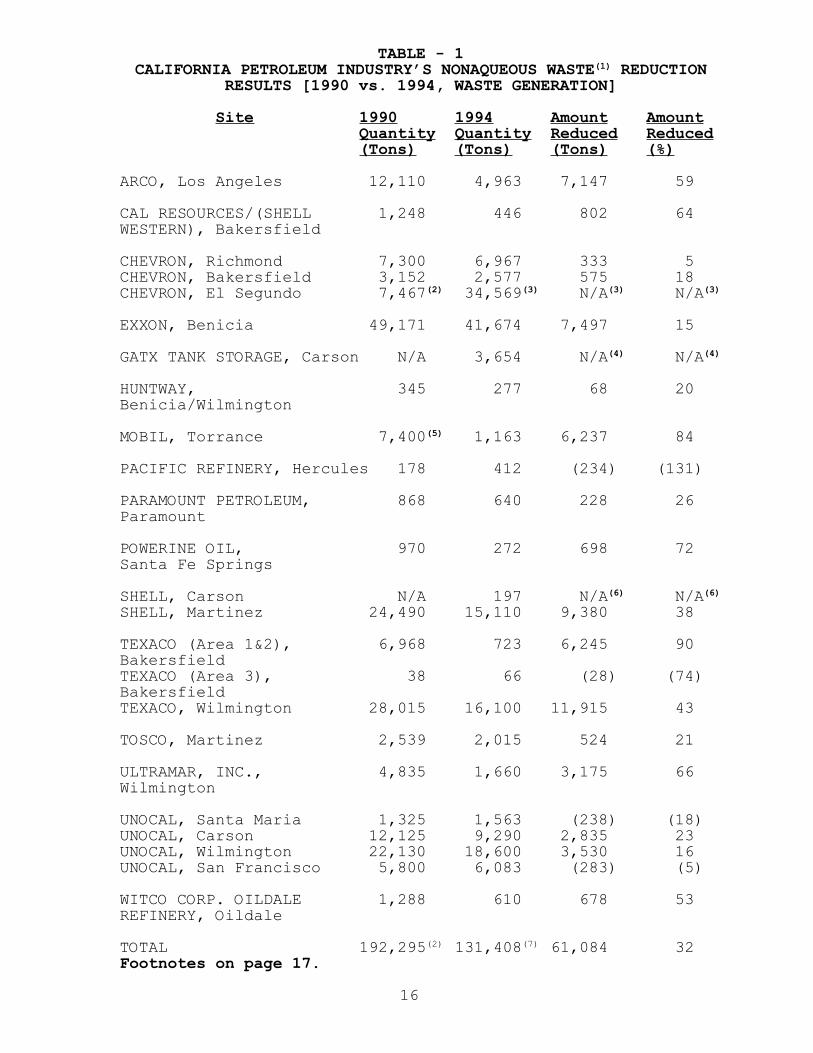
• This is the second source reduction assessment reportfor the petroleum industry. During first cycle, thisindustry - comprised of twenty-four sites - generatedmore than 192,000 tons of SB 14 applicable nonaqueoushazardous waste. These quantities are based on 1990calendar year data determined from a review of theindustry’s 1995 Waste Management Performance Reports.Observed individual nonaqueous waste quantities rangedfrom 38 to 49,000 tons annually. During the 1994calendar year (second cycle) the industry generatedapproximately 169,000 tons (see Table 2) of SB 14applicable nonaqueous hazardous waste. Thisinformation was obtained from the 1995 Source ReductionPlans representing the industry’s twenty-four sitesaffected by SB 14. Four out of the twenty-four sitesincreased their hazardous waste generation ranging from28 to 283 tons (5 to 131 percent) from the 1990calendar year to the 1994 calendar year. Unocal SanFrancisco attributed the increase in waste generationto an increase in the quantity of crude distillation; anormalization of data by production indicates thatUnocal actually reduced its waste per unit of product.
• The comparison does not include the Chevron El Segundosite (among three other sites) because Chevron onlyreported waste disposal quantities for 1990 as opposedto waste generated quantities. The amount of disposalof major waste streams for this site decreased byapproximately 45 percent from 1990 to 1994.
• In 1995, that portion of the petroleum industryaffected by SB 14 projected its ultimate hazardouswaste reduction to be 32 percent of that quantitygenerated by this industry in 1990. This reductionquantity will amount to more than 60,000 tons annually.These estimates do not include aqueous hazardous wastestreated onsite in waste water treatment plants.Aqueous hazardous waste quantity data detailed by thosefacilities generating aqueous waste are presentedseparately in this report.

Nonaqueous Waste Reduction Goal:
• Table 2 outlines nonaqueous hazardous waste datagenerated during calendar year 1994. It also showsindividual site hazardous waste reduction goals forreducing wastes under optimal conditions for the fouryear period 1994-1998 and beyond.
• Hazardous waste generation during 1994 rangedindividually from 66 tons to 41,000 tons, with anaverage generation of approximately 7,000 tons persite. The average hazardous waste reduction goal is31 percent per site and accounts for a total of morethan 2,200 tons for each of the twenty-four SB 14 sitesannually.
• Eighteen out of the twenty-four sites reported theirhazardous waste reduction goals ranged from 1 to 100percent amounting from 7 to 17,000 tons for the nextfour years beginning in 1995. Powerine oil was in theprocess of dismantling its plant prior to selling itoverseas; therefore this facility could not provide ahazardous waste reduction goal information.
• Twenty-four of the California petroleum sitescollectively generated more than 169,000 tons ofnonaqueous, SB 14 applicable hazardous waste. Based onthe estimated goal specified by these facilities intheir Plans, we project the industry collectively iscapable, under ideal conditions, of reducingapproximately 31 percent of its present nonaqueoushazardous waste generation amounting to more than53,000 tons annually during 1994 - 1998 and beyond.
Source Reduction Measures For 1994 Nonaqueous Waste:
• Table 3 identifies the number of major waste streamsand source reduction measures considered, selected andrejected by the petroleum industry based on 1994 data.
• The number of major waste streams varies from 1 to 6among the individual twenty-four sites, with an averageof 3 major waste streams identified per site. Thebreakdown is as follows:
Percentage of Sites No. Major Wastes Streams
13 138 225 317 4 4 5 4 6
12
• The industry considered a total of 217 measures forreducing hazardous waste; more than half (56 percent)were selected and the remaining 44 percent wererejected. Listings of selected and rejected measuresare contained in Appendix B and D.
• The number of measures considered ranged for each sitefrom 1 to 32 with an average of 9 measures consideredper site. More than 2/3 of the sites consideredapproximately 10 measures.
• The number of measures selected ranged for each sitefrom 1 to 21 with an average of 5 measures selected persite. One site selected 21 measures out of 27considered (78 percent). Another site selected 14measures out of 21 considered (67 percent).
• The number of measures rejected varied from 0 to 24with an average of 4 rejected per site. One siterejected 24 measures out of 32 considered (75 percent).Nearly 40 percent of the sites did not reject any ofthe measures considered.
Nonaqueous Hazardous Waste Streams:
• Table 4 displays the number of major nonaqueoushazardous waste streams and the total nonaqueoushazardous waste streams identified in 1994. The totalnumber of nonaqueous hazardous waste streams rangedfrom 1 to 13 with an average of between 8 to 9 persite. Three quarter of the industry declared more than5 total nonaqueous waste streams; half declared morethan 10 total nonaqueous waste streams in 1994.
• Collectively, the industry identified more than32 percent of all 205 nonaqueous waste streams as majorSB 14 waste streams generated during 1994.
Aqueous Hazardous Waste Streams And Projected Reduction:
Unlike nonaqueous hazardous waste, aqueous hazardouswaste quantities comparison between 1990 and 1994 is notapplicable. For the initial documents prepared during thefirst cycle (September 1991), many of the petroleum industrygenerators did not address aqueous waste streams in theirsource reduction evaluation which are now included in theircurrent 1995 documents. SB 1133 was enactedSeptember 5, 1991 and clarified the requirements forevaluating both aqueous and nonaqueous waste streams. For1995 documents, due September 1, 1995, generators arerequired to determine the total quantity of waste water
13
generated, then conduct an additional calculation excludingthe consideration of waste waters to determine the major nonaqueous waste streams.
• Table 5 summarizes aqueous hazardous waste generationdata analyzed during calendar year 1994 along withappropriate waste reduction information and applicablemeasures.
• The applicable SB 14/SB 1133 individual site aqueoushazardous waste generation in 1994 ranges from 620 tonsto 7.2 million tons. Aqueous waste is defined as thehazardous waste stream processed in a waste watertreatment unit which discharges to a publicly ownedtreatment works or under a National Pollutant DischargeElimination System (NPDES) permit as specified in theFederal Water Pollution Control Act, as amended(33 U.S.C. Sec. 1251 and following). [Reference:Health and Safety Code 25244.19(b)(3)(A) and (B)].Twelve sites indicated that they did not generateSB 14/SB 1133 applicable waste during 1994; one sitewas not able to provide aqueous waste generation databy the time of report publishing.
• Collectively, in 1994, the industry generated 16.78million tons of aqueous waste. Approximately46 percent of sites reported their aqueous wastesgeneration data for 1994. Most of the remainder didnot generate hazardous aqueous wastes. The elevensites reporting aqueous waste collectively selected 12source reduction measures.
• The number of source reduction measures selected byeach site ranged from 0 to 5, with an average ofbetween 1 to 2 measures per site. DTSC noticed atleast 3 sites that were proactive in reducing aqueouswaste stream generation and implemented severalmeasures that were successful in annually reducingseveral thousands of tons of aqueous waste prior to1995.
• Only 3 sites individually targeted reduction ofgenerated aqueous waste(s) which ranged from 13 percent(9402 tons) to 25 percent (0.33 million tons) annually.Six sites were unable to provide a specific aqueouswaste reduction goal or reduction tonnage.
• It is estimated that collectively, the petroleumindustry will reduce approximately 2.0 percent or0.34 million tons annually of hazardous aqueous wasteduring 1994 - 1998 and beyond.
14

• The petroleum industry generated a total of 16,949,931tons of aqueous and nonaqueous SB 14/SB 1133 applicablehazardous waste in 1994, and projected to reduce393,030 tons annually after 1994 (Refer to Tables 2 andTable 5). The nonaqueous hazardous waste generation in1994, and estimated reduction of nonaqueous waste after1994 amounted to be 1.1 and 0.4 percent of the totalaqueous and nonaqueous wastes generated in 1994.
• When all of the selected measures are implemented, theindustry will be saving between $6.7 to $40.1 millionannually by reducing projected nonaqueous waste alone.This figure will be even greater considering the largequantity of aqueous waste that will be reduced. Due tocomplexity of petroleum refinery processes it isdifficult to figure dollar savings merited to thereduction of aqueous waste.
15

16
TABLE - 1CALIFORNIA PETROLEUM INDUSTRY’S NONAQUEOUS WASTE(1) REDUCTION
RESULTS [1990 vs. 1994, WASTE GENERATION]
Site 1990 1994 Amount AmountQuantity Quantity Reduced Reduced(Tons) (Tons) (Tons) (%)
ARCO, Los Angeles 12,110 4,963 7,147 59
CAL RESOURCES/(SHELL 1,248 446 802 64WESTERN), Bakersfield
CHEVRON, Richmond 7,300 6,967 333 5CHEVRON, Bakersfield 3,152 2,577 575 18CHEVRON, El Segundo 7,467(2) 34,569(3) N/A(3) N/A(3)
EXXON, Benicia 49,171 41,674 7,497 15
GATX TANK STORAGE, Carson N/A 3,654 N/A(4) N/A(4)
HUNTWAY, 345 277 68 20Benicia/Wilmington
MOBIL, Torrance 7,400(5) 1,163 6,237 84
PACIFIC REFINERY, Hercules 178 412 (234) (131)
PARAMOUNT PETROLEUM, 868 640 228 26Paramount
POWERINE OIL, 970 272 698 72Santa Fe Springs
SHELL, Carson N/A 197 N/A(6) N/A(6)
SHELL, Martinez 24,490 15,110 9,380 38
TEXACO (Area 1&2), 6,968 723 6,245 90BakersfieldTEXACO (Area 3), 38 66 (28) (74)BakersfieldTEXACO, Wilmington 28,015 16,100 11,915 43
TOSCO, Martinez 2,539 2,015 524 21
ULTRAMAR, INC., 4,835 1,660 3,175 66Wilmington
UNOCAL, Santa Maria 1,325 1,563 (238) (18)UNOCAL, Carson 12,125 9,290 2,835 23UNOCAL, Wilmington 22,130 18,600 3,530 16UNOCAL, San Francisco 5,800 6,083 (283) (5)
WITCO CORP. OILDALE 1,288 610 678 53REFINERY, Oildale
TOTAL 192,295(2) 131,408(7) 61,084 32Footnotes on page 17.

TABLE 1 - FOOTNOTES
(1) The waste data in Table 1 represents only nonaqueous,SB 14 applicable, hazardous waste generated as reported ineach site’s SB 14 Hazardous Waste Performance Report.Nonaqueous waste for SB 14 applicable hazardous waste can bedefined as: “the hazardous waste stream which is notprocessed in a waste water treatment unit”. The definitionof aqueous waste stream is outlined on page 8.
(2) Hazardous Waste “disposed” quantity. Not included inthe Total. Disposed quantities [major waste streams] for1990 and 1994 are 7,476 and 3,880 tons respectively.
(3) Since the 1990 quantity is disposed vs. 1994 quantity isgenerated the “Amount Reduced (Tons)” and “Amount Reduced(%)” can not be determined.
(4) GATX mentioned that it was not captured during 1990 dueto lower threshold SB 14 applicable hazardous wastegeneration quantity. Therefore its baseline and reportingyears are same i.e. 1994. Hence “Amount Reduced (Tons) andAmount Reduced (%) are not determined.
(5) Revised figure - In 1990 the hazardous waste generationquantity was erroneously reported.
(6) The Shell Carson plant is the result of a significantreduction in overall facility size and operation of whatformerly was the Wilmington Manufacturing Complex. InDecember 1991 a portion of the refinery was sold. Therefinery wrote their first SB 14 documents in 1994.Therefore the baseline and reporting years are same i.e.,1994. Hence “Amount Reduced (Tons) and Amount Reduced (%)are not determined.
(7) The 1994 total does not include the GATX quantity(3,654 tons) because 1990 data are not available. The totalalso does not include Chevron El Segundo quantity(34,569 tons).
Amounts noted in ( ) indicate an increase in hazardous wastegeneration.
17

TABLE - 2(1)CALIFORNIA PETROLEUM INDUSTRY FOUR YEAR HAZARDOUS WASTE
(NONAQUEOUS) REDUCTION GOAL [1994 - 1998]
Site 1994 Hazardous Goal GoalWaste Generation Reduction Quantity(Tons) Percentage (Tons)
( % )(2)
ARCO, Los Angeles 4,963 20 992
CAL RESOURCES/(SHELL 446 100 446WESTERN), BakersfieldCHEVRON, Richmond 6,967 18 1,254CHEVRON, Bakersfield 2,577 20 515CHEVRON, El Segundo 34,569 60 21,040
EXXON, Benicia 41,674 5 2,000
GATX TANK STORAGE, 3,654 29 1,060Carson
HUNTWAY, 277 17 46Benicia/Wilmington
MOBIL, Torrance 1,163 43 507
PACIFIC REFINERY, 412 19 78Hercules
PARAMOUNT PETROLEUM, 640 16 102Paramount
POWERINE OIL, 272 N/A(3) N/ASanta Fe Springs
SHELL, Carson 197 80 158SHELL, Martinez 15,110 10 1,493
TEXACO (Area 1&2), 723 10 72BakersfieldTEXACO (Area 3), 66 10 7BakersfieldTEXACO, Wilmington 16,100 1 200
TOSCO, Martinez 2,015 20 403
ULTRAMAR, INC., 1,660 5 80Wilmington
UNOCAL, Santa Maria 1,563 57 890UNOCAL, Carson 9,290 29 2,694UNOCAL, Wilmington 18,600 92 17,112UNOCAL, San Francisco 6,083 29 1,764
WITCO CORP. OILDALE 610 95 580
TOTAL 169,359(4) 31 53,493(5)Footnotes on page 19.
18

TABLE 2 - FOOTNOTES
(1) The waste data in Table 2 represents only nonaqueous,SB 14 applicable, hazardous waste generated as reported ineach site’s 1995 SB 14 Hazardous Waste Source ReductionPlan. Nonaqueous waste for SB 14 applicable hazardous wastecan be defined as: “the hazardous waste stream which is notprocessed in a waste water treatment unit”. The definitionof aqueous waste stream is outlined on page 8. The aqueouswaste data are contained in Table 5, page 24.
(2) In most cases, the percent goal for each site was takenfrom its 1995 Plan. In few cases, when the goal was notspecified in site’s Plan, DTSC projected the goal based onthe planned waste reduction information provided in thePlan.
(3) Not applicable - Powerine indicated that it was planningto sell the business and equipment to an entity overseas.
(4) The “Total” quantity differs from Table 1 becausea) Powerine waste quantity is not included in Table 2 andb) Chevron El Segundo, and GATX, 1994 waste generationquantities are included in the Table 2 Total, but are notincluded in the Table 1 Total.
(5) The overall waste reduction goal for the petroleumindustry was derived by using “total goal quantity” and“total 1994 nonaqueous hazardous waste generation” quantity.
19

TABLE - 3CALIFORNIA PETROLEUM INDUSTRY 1994 SOURCE REDUCTION MEASURES
FOR NONAQUEOUS WASTE(1)
Site Number Number Number of Number ofof Major of Measures Measures MeasuresWastes Considered Selected Rejected
ARCO, Los Angeles 2 2 2 0
CAL RESOURCES/(SHELL 1 1 1 0WESTERN), Bakersfield
CHEVRON, Richmond 2 32 8 24CHEVRON, Bakersfield 3 12 9 3CHEVRON, El Segundo 3 12 6 6
EXXON, Benicia 1 7 3 4
GATX TANK STORAGE, Carson 2 9 5 4
HUNTWAY, 1 7 4 3Benicia/Wilmington
MOBIL, Torrance 3 14 8 6
PACIFIC REFINERY, Hercules 4 7 4 3
PARAMOUNT PETROLEUM, 4 4 4 0Paramount
POWERINE OIL, 3 N/A N/A N/ASanta Fe Springs
SHELL, Carson 2 21 14 7SHELL, Martinez 2 8 8 0
TEXACO (Area 1&2), 3 2 2 0BakersfieldTEXACO (Area 3), 4 2 2 0BakersfieldTEXACO, Wilmington 2 12 4 8
TOSCO, Martinez 4 6 5 1
ULTRAMAR, INC., 6 1 1 0Wilmington
UNOCAL, Santa Maria 3 1 1 0UNOCAL, Carson 2 15 4 11UNOCAL, Wilmington 2 14 5 9UNOCAL, San Francisco 5 27 21 6
WITCO CORP. OILDALE 2 1 1 0REFINERY, Oildale
TOTAL 66(2) 217(3) 122(3) 95(3)
Footnotes on page 21.20

TABLE 3 - FOOTNOTES
(1) Based on 1994, SB 14 applicable hazardous wastegeneration quantities.
(2) The total of 66 waste streams are comprised of 16California waste codes outlined in Appendix C.
(3) Total of measures columns will reflect multiple countsof the same measure considered by other sites.
21

TABLE - 4CALIFORNIA PETROLEUM INDUSTRY
1994 NONAQUEOUS HAZARDOUS WASTE STREAMS
Site Number of Number ofHazardous Major WasteWaste Streams Streams
ARCO, Los Angeles 9 2
CAL RESOURCES/(SHELL 1 1WESTERN), Bakersfield
CHEVRON, Richmond 10 2CHEVRON, Bakersfield 10 3CHEVRON, El Segundo 10 3
EXXON, Benicia 13 1
GATX TANK STORAGE, Carson 4 2
HUNTWAY, 2 1Benicia/Wilmington
MOBIL, Torrance 7 3
PACIFIC REFINERY, Hercules 5 4
PARAMOUNT PETROLEUM, 4 4Paramount
POWERINE OIL, 10 3Santa Fe Springs
SHELL, Carson 5 2SHELL, Martinez 12 2
TEXACO, (Area 1 and 2), 13 3BakersfieldTEXACO, (Area 3), 10 4BakersfieldTEXACO, Wilmington 9 2
TOSCO, Martinez 12 4
ULTRAMAR, INC., 12 6Wilmington
UNOCAL, Santa Maria 8 3UNOCAL, Carson 9 2UNOCAL, Wilmington 11 2UNOCAL, San Francisco 11 5
WITCO CORPORATION OILDALE 8 2REFINERY, Oildale
TOTAL 205(1) 66(1)
Footnotes on page 23.
22

TABLE 4 - FOOTNOTES
(1) Total of Waste Streams Columns will reflect multiplecounts of the same waste stream appropriate to “differentsites”. The total is comprised of the 16 California WasteCodes (CWC) outlined in Appendix C.
23
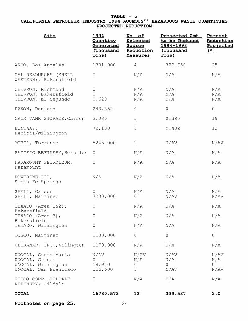
TABLE - 5CALIFORNIA PETROLEUM INDUSTRY 1994 AQUEOUS(1) HAZARDOUS WASTE QUANTITIES
PROJECTED REDUCTION
Site 1994 No. of Projected Amt. PercentQuantity Selected to be Reduced ReductionGenerated Source 1994-1998 Projected(Thousand Reduction (Thousand (%)Tons) Measures Tons)
ARCO, Los Angeles 1331.900 4 329.750 25
CAL RESOURCES (SHELL 0 N/A N/A N/AWESTERN), Bakersfield
CHEVRON, Richmond 0 N/A N/A N/ACHEVRON, Bakersfield 0 N/A N/A N/ACHEVRON, El Segundo 0.620 N/A N/A N/A
EXXON, Benicia 243.352 0 0 0
GATX TANK STORAGE,Carson 2.030 5 0.385 19
HUNTWAY, 72.100 1 9.402 13Benicia/Wilmington
MOBIL, Torrance 5245.000 1 N/AV N/AV
PACIFIC REFINERY,Hercules 0 N/A N/A N/A
PARAMOUNT PETROLEUM, 0 N/A N/A N/AParamount
POWERINE OIL, N/A N/A N/A N/ASanta Fe Springs
SHELL, Carson 0 N/A N/A N/ASHELL, Martinez 7200.000 0 N/AV N/AV
TEXACO (Area 1&2), 0 N/A N/A N/ABakersfieldTEXACO (Area 3), 0 N/A N/A N/ABakersfieldTEXACO, Wilmington 0 N/A N/A N/A
TOSCO, Martinez 1100.000 0 0 0
ULTRAMAR, INC.,Wilington 1170.000 N/A N/A N/A
UNOCAL, Santa Maria N/AV N/AV N/AV N/AVUNOCAL, Carson 0 N/A N/A N/AUNOCAL, Wilmington 58.970 0 0 0UNOCAL, San Francisco 356.600 1 N/AV N/AV
WITCO CORP. OILDALE 0 N/A N/A N/AREFINERY, Oildale
TOTAL 16780.572 12 339.537 2.0
Footnotes on page 25. 24

TABLE 5 - FOOTNOTES
(1) Aqueous Hazardous Waste stream is defined as a hazardouswaste stream processed in a waste water treatment unit whichdischarges to a publicly owned treatment works or under aNational Pollutant Discharge Elimination System (NPDES)permit as specified in the Federal Water Pollution ControlAct, as amended (33 U.S.C. Section 1251 and following).[Reference: SB 1133, 1991, Health and Safety Code25244.19(b)(3)(A) and (B)].
• N/A - Not Applicable
• N/AV - Not Available
25

IV. SOURCE REDUCTION MEASURES
DTSC has reviewed Source Reduction documents preparedby the 24 California petroleum facilities affected by SB 14.These 24 sites collectively generated a total of 66nonaqueous and several aqueous major hazardous wastestreams, considered 217 measures for nonaqueous wastes andof these selected 122 measures (12 additional measures wereselected for aqueous wastes) to reduce hazardous wasteduring 1998 and beyond. A detailed breakdown of theseselected measures by site is presented in Table 3 andTable 5, and a listings of selected and rejected measuresare outlined in Appendix B and D. The following discussiondescribe key source reduction example(s) taken from each ofthe 24 sites. These examples represent the cost effectiveapproaches that are generally applicable throughout theindustry.
ARCO, Los Angeles Refinery:
Waste Water Reduction: ARCO refinery waste water is acombination of process water and stormwater, since it doesnot have a separate stormwater sewer. The refinery reducedits discharge of waste water, which is hazardous waste, byan estimated 85 percent from 1990 to 1994. ARCO’s processwaste waters originate from tank draws, desalters, refineryoperating units and cooling tower blowdown. Waste water isprocessed to meet specification and then it is discharged toa POTW. Benzene concentrations of 0.5 ppm or greater (asbenzene) results in this waste water being classified as aRCRA hazardous waste due to toxicity. Potential sourcereduction options for refinery waste water include both1) reducing the total volume requiring discharge to thePOTW; and 2) lowering the benzene concentration so that thewater may be classified as nonhazardous.
The volume of waste water generated by ARCO dependsprimarily on the refinery’s water consumption, and thequantity of rainfall. ARCO has a long history of waterconservation efforts and has consistently reducedconsiderable waste water volume over the last three years.This has been done due, at least in part, to a variety ofwater reuse projects.
During the last ten years, wherever possible, therefinery has segregated the stormwater drainage from processwaste water. Segregation prevents storm water from becomingcontaminated with process hydrocarbons. Segregation alsoprevents oil/water sludge formation.
26

The refinery implemented several source reductionprojects to reduce benzene concentration in waste water tobelow 0.5 ppm. These projects were completed by 1992. In1994, the benzene level of the final effluent was below 0.5ppm 80 percent of the time. The following key projects wereimplemented in the last four years, which contributed to thebenzene reduction: 1) Installation of closed loop samplingsystem 2) Segregation and recycling of high benzeneconcentration waters and 3) Benzene waste water stripping.
ARCO is committed to further reduce, benzeneconcentration in refinery waste water. In order to achievethis result, the refinery will continue promoting anincreased awareness by plant personnel of the importance ofrestricting hydrocarbons from entering the sewer. ARCOintends to accomplish this increased awareness by allrefinery personnel by publishing articles in the refinerynewspaper and conducting frequent training sessions foroperation and maintenance personnel.
Agricultural Use Of Spent Polymerization Catalyst: TheCatalytic Polymerization Unit converts propylene from theFluid Catalytic Cracking (FCC) unit into gasoline blendingstock and commodity chemicals. This reaction occurs in tenvertical reactors and is activated by the action ofphosphoric acid on extruded silica-alumina pellets. Thismaterial is a cationic polymer catalyst. Spent catalyst isremoved from the reactors approximately eighty times peryear. This spent catalyst is a non-RCRA hazardous waste dueto its corrosivity which is due to its phosphoric acidcontent.
Phosphoric acid is widely use for producing fertilizerto be used in agricultural and horticultural applications.A project is underway to divert this material from thelandfill to applications in the agricultural industry.
CAL RESOURCES (Formerly Known as SHELL WESTERN E & P INC.),Bakersfield:
Refractory Waste As A Non-Routine Waste: Refractorybrick is used to construct the furnace box of steamgenerators and may be used to construct or line other hightemperature process units. With prolonged use, therefractory becomes impregnated with nickel and vanadiumintroduced by the crude oil fuel. The concentrations ofnickel and vanadium are sufficient to cause this refractoryto be classified as hazardous. Hazardous refractory waste isgenerated when the process unit is demolished or whendamaged refractory is repaired during routine maintenanceoperations. Cal Resources is switching from crude oil to
27

gas fuel. By using gas, the damaged refractory will not beclassified as hazardous because fuel gas does not containnickel or vanadium. Although not an SB 14 waste stream dueto its non-routine generation, Cal Resources’ elimination ofthis waste stream reduces their hazardous waste managementcosts and future liability.
CHEVRON, Bakersfield:
Reduce Sand Blast Grit: Sand blast grit is generatedduring the surface stripping/cleaning of equipment,platforms and storage tanks. Sand blast grit is potentiallya hazardous waste due to contamination by metal-containingpaints and primers stripped from the equipment.Occasionally metals contamination can appear in the sandblast grit due to the base metal content of the equipmentitself. Chevron selected two measures for implementationand plans to modify its current decision-making procedurethat is used to determine painting/sand blasting operationfrequently. It will also determine which paints and primersare best for use. Painting/sand blasting frequency and thepaint type selected will depend on site specific factorsincluding economic and compliance issues present at the timeof repainting.
Survey/Audit to Reduce Crude Tank Bottoms: Tankbottoms are the result of solids such as sand, dirt, etc.settling out of produced crude oil and onto the bottom oftanks, vessels, and other processing equipment. In thepast, certain tank bottoms have been determined to be ahazardous waste due to toxicity. This toxicity may beassociated with crude oil metals that adhere to the settledsolids. Chevron’s present tank cleaning methods includewater washing of these solids from the tanks and vessels.
Chevron has decided to conduct the following threesurvey/audit measures: 1) improve tank cleaning procedures2) improve the chemical and mechanical processes to removewater, and solids from process streams and 3) examine sandcontrol processes to find ways to reduce sand carryover.The procedures and approach of these three measures involveestablishing the scope and detail of the project and thenconducting the audit/survey. The survey/audit approach maybe conducted by either an outside consultant or by Chevronpersonnel. Upon completion of the survey/audit, identifiedprocedural improvements will be evaluated to determinespecific applicability and implementation feasibility.
28

CHEVRON, El Segundo Refinery:
Oily Sludge Source Reduction through Inspection andRepair of Drainage Systems: The Chevron El Segundo refinerygenerated 20,700 tons of this waste during 1994. The wasteis generated during passive and active separation of oil andsolids from waste water streams. This measure would reducethe formation of oil/water separation sludge generation byminimizing the amount of sand originally entering thedrainage system. Capital and O & M costs are estimated atmore than ten million dollars. Due to the high capitalcosts, Chevron mentioned that the project could extendbeyond the present SB 14 four-year cycle.
CHEVRON, Richmond Refinery:
Eliminate the Use of Sandbags for Plugging Sewers: TheChevron Richmond Refinery generated 5,832,000 pounds peryear API separator and other sludges. API separator sludgeis generated during the gravitational separation of wastesolids from refinery process waste waters in its APIseparators. This waste stream is made up of tank water drawsolids, rust, scale, and other process equipmentcontaminants and soil runoff. Much of these solidsoriginate from sandbags used to plug stormwater drainsduring maintenance activity. Deterioration of the sandbags,spillage of sand and gravitational separation of solids fromwaste water flows are key contributors to this waste stream.
Chevron will use alternate methods for plugging processdrains, using commercial products such as Insert-A-Seals orDuck ponds. Economic review and feasibility studies werescheduled to be performed during 1996. Approximately560,000 pounds per year of this waste is estimated to bereduced upon implementation of this measure.
Screen Out Inert Ceramic Support Spheres from SpentCatalyst and Reuse Spheres: Spent catalyst is generatedfrom processes that treat, crack, or reform hydrocarbonstreams by passing these streams over a metal impregnatedcatalyst. These catalysts are manufactured with nickel,molybdenum or other non-RCRA metal contaminants thattypically cause them to be classified as hazardous whenspent. These metals are required to achieve the necessaryreaction to process hydrocarbons through operations such ascatalytic hydrocracking, hydrotreating, and hydrogenmanufacturing. These catalysts become worn out over time.The Chevron refinery generated more than five million poundsof total spent catalyst in the reporting year 1994.
29

Chevron will screen the spent catalyst to removesupport spheres for reuse as fresh catalyst support in thereactors. Operating cost, analytical cost and return oninvestment are estimated at $100,000 per year, $2,000 peryear and more than 100% respectively. Chevron estimatedthat nearly 500,000 pounds/year will be reduced.
EXXON, Benicia:
Improved Handling of Electrostatic Precipitator (ESP)Fines: Exxon uses an electronic precipitator to collectFluid Catalytic Cracking Unit (FCCU) catalyst particles(fines) that pass through two furnaces. The ESP fines arecollected by baghouses and deposited into rolloff boxeswhich are then taken to another part of the refinery fortransfer onto bulk transport trucks suitable for thismaterial. Although this material is not regulated ashazardous waste in California, fugitive emissions andspills/leakage from handling may enter the refinery sewersystem where they can cause up to a ten-fold increase insewer sludge.
Exxon has proposed a direct transfer of ESP fines intoa transport vehicle compared to the current practices ofmoving a rolloff box to another part of the refinery whereit can then be loaded to a transport vehicle. This currentpractice causes increased leakage or spillage of thismaterial. It appears that 5 to 10 pounds of ESP fines arelost for each ton handled. Based on the 1994 quantityhandled, ESP fines loss would be approximately 2.6 to 5.2tons. Since each pound of solids entering into sewer cangenerate 10 pounds of oil/water separation solids,eliminating the loss of ESP fines may reduce the waste watertreatment solids by 25 to 50 tons per year. It is estimatedthat implementing this source reduction measure will cost$350,000. However, inplant management costs of about$150,000 per year will be significantly reduced and willresult in a 35 percent discounted cash flow rate of return.This potential source reduction measure is attractivebecause it will reduce generation of oil/water separationsolids by removing dust particles at the source, prior toentering the sewer.
Improve Operation of the Desalter: Crude oil must bedesalted before it can be processed in the refinery.Removing salt reduces the corrosion on refinery processequipment. Salt removal is done in a desalter vessel whichuses electric current, chemical additives, and water totransfer the salts into a water phase that is thendischarged to the waste water treatment plant. The desaltedoil phase then enters the crude preheat and distillation
30
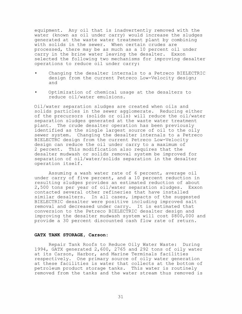
equipment. Any oil that is inadvertently removed with thewater (known as oil under carry) would increase the sludgesgenerated at the waste water treatment plant by combiningwith solids in the sewer. When certain crudes areprocessed, there may be as much as a 10 percent oil undercarry in the brine water leaving the desalter. Exxonselected the following two mechanisms for improving desalteroperations to reduce oil under carry:
• Changing the desalter internals to a Petreco BIELECTRICdesign from the current Petreco Low-Velocity design;and
• Optimization of chemical usage at the desalters toreduce oil/water emulsions.
Oil/water separation sludges are created when oils andsolids particles in the sewer agglomerate. Reducing eitherof the precursors (solids or oils) will reduce the oil/waterseparation sludges generated at the waste water treatmentplant. The crude desalter operation has been previouslyidentified as the single largest source of oil to the oilysewer system. Changing the desalter internals to a PetrecoBIELECTRC design from the current Petreco Low-Velocitydesign can reduce the oil under carry to a maximum of2 percent. This modification also requires that thedesalter mudwash or solids removal system be improved forseparation of oil/water/solids separation in the desalteroperation itself.
Assuming a wash water rate of 6 percent, average oilunder carry of five percent, and a 10 percent reduction inresulting sludges provides an estimated reduction of about2,500 tons per year of oil/water separation sludges. Exxoncontacted several other refineries that have installedsimilar desalters. In all cases, impacts of the suggestedBIELECTRIC desalter were positive including improved saltremoval and decreased under carry. It is estimated thatconversion to the Petreco BIELECTRIC desalter design andimproving the desalter mudwash system will cost $800,000 andprovide a 30 percent discounted cash flow rate of return.
GATX TANK STORAGE, Carson:
Repair Tank Roofs to Reduce Oily Water Waste: During1994, GATX generated 2,600, 2765 and 292 tons of oily waterat its Carson, Harbor, and Marine Terminals facilitiesrespectively. One primary source of oily water generationat these facilities is water that collects at the bottom ofpetroleum product storage tanks. This water is routinelyremoved from the tanks and the water stream thus removed is
31

referred to as “water draw”. The water draw contains a highportion of petroleum product due to the desire to remove asmuch water as possible from products. During 1994, oilywater generated from water draws at the Carson and HarborTerminal was either diverted to slop tanks for subsequenttransport to an off-site hazardous waste treatment facilityfor recycling and disposal, or pre-treated at the Carsononsite waste water treatment plant for subsequent dischargeto a POTW.
The Carson facility has several storage tanks; two ofthese tanks have damaged roofs that allow accumulation ofrain water in the tanks. GATX is planning to repair the twodamaged petroleum tank roofs at the Carson terminalfacility. Implementation of this measure would result in areduction of storm water infiltration into the two petroleumproduct storage tanks. It is estimated that all of thesefacilities combined can reduce at least 750 tons per year ofoily waste water once the tank roofs are repaired. GATXbelieves that this measure is technically feasible and thefinal product quality will improve by completely excludingrainwater infiltration. The capital cost of repairing thetwo tank roofs is approximately $550,000.
Install Additional Sumps and Sloping Tank Bottoms:There are several factors such as water draw described abovethat contribute to generating oily waste water at GATX’sthree facilities. On occasion, the contents of a tank andits associated pipelines are emptied for cleaning purposes.During a typical tank cleaning, fresh water is sprayed oninner tank surfaces laden with petroleum residuals. Theamount of water used in tank cleaning operations is directlyproportional to the amount of residual tank bottoms productpresent. Additionally, sumps and sloped bottoms willfacilitate draining residual product and help minimize theamount of product that contacts and contaminates wash water.Cleaning only a thin residual film reduces the amount ofwater necessary for tank cleaning operations and helpsminimize product/water contamination.
In the past few years, GATX has been installing sumpsand sloping bottoms when constructing new tanks, which mayrequire frequent product changes. The capital costsassociated with retrofitting all existing tanks with slopingbottoms and sumps is estimated to be $12,000,000. Underthis option, GATX will continue future installation ofsloping bottoms if these measures can be economicallyjustified on a case by case basis.
32

HUNTWAY REFINING COMPANY, Wilmington:
Isolate Water/Oil Recycling Treatment (WORT) System:Oil/water separation sludge solids are generated as theresult of recycling oily process water and storm waters inthe refinery’s WORT system. The WORT system includes aseries of oil/water separator tanks for the separation ofoil and solids from the waste water stream. Oil recoveredfrom this system is recycled back to the process. TheCalifornia waste code for this waste is CWC 222 oil/waterseparator sludge.
Huntway will isolate the drains from storm water inflowand hence reduce both the solids quantity and storm waterentering the WORT system. This method will be implementedby berming the selected sections of the process area.Huntway will spend a considerable amount of attention toemployee health and safety by eliminating tripping hazardsas it conducts its berming activity. It is estimated thatapproximately 90 tons of waste will be reduced. The capitalcost and annual maintenance cost have been estimated at$10,000 and $1,000 respectively. The payback period isestimated at 2.5 years.
Segregate Boiler Blowdown: Huntway selected thismeasure for further study. Hard water from boiler blowdownmay contribute to waste water sludge accumulation. It isassumed that the hardness in boiler blowdown precipitatesand accumulates in the WORT system as sludge. Huntway willanalyze accumulated sludge to determine what percentageconsists of boiler blowdown solids. Huntway will thenevaluate the feasibility of segregating boiler blowdown fromthe waste water stream.
MOBIL OIL, Torrance Refinery:
Reduction of Aqueous Solutions with OrganicResidues < 10%: Mobil generated more than 5 million tons ofthis waste in 1994. Process waste water enters into theindustrial waste water treatment plant (IWW) at manydifferent places in the refinery. The sewer system whichbrings process waste waters into the IWW is commonlyreferred to as the “oily water sewer” or the “processsewer”. The process sewer system is segregated from stormwater sewer system. The following are typical process sewerwaste water sources:
1) Drains in the process unit - All process units in therefinery are constructed on concrete pads, these padsdrain to the process sewer. This is done so thatdrips, leaks, or spills of hydrocarbon material do not
33

contaminate adjacent soil. The concrete pads arewashed with steam, water and cleaning agent on aperiodic basis. The water and any hydrocarbons on thesurface of the pad are drained to the process sewer.
2) Drains on pump pads and compressor pads - Rotatingequipment such as pumps and compressors are commonsources of hydrocarbon material leaks. When leaksoccur, this material is allowed to drain to the oilywater sewer.
3) Drains at sample points - The operation of the refineryrequires frequent sampling of intermediate and finalproducts. At many sample points, sample ports areflushed into the sewer for sufficient time to ensurethat the line from the process is purged so that thesample taken is representative. Where practical, therefinery has installed a closed loop sampling systemwhich avoids draining into process sewer.
4) Vacuum truck wash out area and heat exchanger bundlecleaning pad - In the case of vacuum truck operation,water and hydrocarbons from the vacuum truck cleaningarea enter the process sewer. In the case of the heatexchanger bundle cleaning pad the material entering thesewer consists of water and hydrocarbons from thehydroblasting and steam cleaning of process equipment,mainly heat exchanger tube bundles.
5) Drains inside tank dikes - Inside the tank dike thereis often a process drain. Material spilled from tanksis often drained to the process sewer for recovery.
6) Oil water separation vessels - In vessels where wateris separated from hydrocarbons the water fraction isoften drawn off and sent to the process sewer.
7) Boiler blow down - Steam boiler blowdown water is sentto the process sewer.
8) Water draws on storage tanks - Certain product orintermediate product storage tanks will over timeaccumulate water. This water is drawn off and sent tothe process sewer.
In the IWW hydrocarbons are separated and the water isdischarged to a POTW. Oil separated by gravity is called“recovered oil” and it is not regulated. Recovered oil isreturned to the refining process by addition to the crudefeed unit. Oily sludges generated in the IWW are returnedto the coker to recover the hydrocarbon content. A small
34

quantity of contaminated debris and certain pieces ofreplaced equipment are generated in the IWW and disposed ofin a landfill.
The refinery implemented one key process sewer measure:exclude hazardous substances from the process sewer. Forexample, the refinery now covers process sewer drains duringmaintenance periods to avoid dust and debris from catalystchange outs from entering the sewer. This prohibitsformation of large amount of sludge and reduces sludgerecycling costs.
The refinery manufactures “clean fuels” (CARBgasoline). This has a positive effect on the total amountof benzene present in the refinery process waste waters.The more stringent CARB gasoline formulation allows onlyabout half the amount of benzene in gasoline. The refinerymade major process changes and decommissioned a process unitwhich was contributing high levels of benzene and otheraromatic blending stock in their gasoline products. Thesechanges were scheduled during the 1995-96 period and theCARB gasoline production was commenced during the firstquarter of 1996.
PACIFIC REFINING COMPANY, Hercules:
Install Close Loop Sampling Ports: Pacific RefiningCompany will install closed loop sampling ports at allprocess units throughout the plant. This measure willreduce the amount of oil entering into their waste watertreatment plant, hence minimizing oily sludge generation.Pacific estimated a 10 tons per year reduction of thesludge. Capital cost is approximately $30,000 with apayback period of approximately 2.3 years.
PARAMOUNT PETROLEUM COMPANY, Paramount:
Tank Bottom Waste Reduction using a Filter Press: Tankbottom sludge occurs due to water and sediment settling outof the stored product in the tank and accumulating on thebottom. The use of a filter press results in recovering andseparating as much oil and water as possible. Oil is thenreprocessed through the refinery’s processes and the waterdirected to the refinery waste water system and dischargedto a POTW. If the filter cake’s heating value is more than5,000 BTU per pound, the material can be used as fuel forpermitted cement kilns.
35

POWERINE OIL COMPANY, Santa Fe Springs:
No Key Measures: Powerine was unable to prepare sourcereduction measures for 1994 since the company ceasedoperation in July 1995. Powerine signed a contracttransferring ownership of the Refinery’s assets (equipment)to a third party who plans to dismantle the refinery andreassemble the plant overseas. Therefore, Powerine will nolonger routinely generate hazardous waste. Powerine’s 1994,Source Reduction Plan will be updated in the future, ifnecessary.
SHELL OIL, Carson:
Reduce Hydrocarbon Spills and Leaks in the Pump PadArea: Under normal operating conditions, Shell hasexperienced seal leaks and lubricating oil drippings as themajor sources of waste hydrocarbons in their pump pad area.Pump bases serve as collector pans and are usually providedwith a drain hole. These pans must be kept clean of solidsfor waste hydrocarbons to adequately drain. Shell willadminister special efforts to drain the equipment and linesprior to repairs, and hence avoid hydrocarbon spillage.This will help Shell reduce filter cake. Shell believesthat the change in the hazardous waste generation could besignificant through implementation of this selected measure.
Note: The Shell Carson plant is the result of a significantreduction in an overall facility size and operations of whatwas formerly the Wilmington Manufacturing Complex, arefinery which sold the majority of it’s operation toanother oil company.
SHELL OIL, Martinez:
Segregate High Salt Waters directly to the Biotreater:Stripped sour water and boiler blowdown are two of the manyprecursors to oil/water separator sludge generated bysuspended and precipitated solids which form sludges in thepresence of oil. Contaminants in these streams areprimarily inorganic, and could be managed downstream of theAPI and dissolved air flotation units. Shell has anexisting pipeline that could be used for the purpose ofrouting stripped sour water and boiler blowdown streamsdirectly to the biotreater. The only costs associated withimplementation might be the effort required to modify one ortwo operational procedures. Shell expects to reduceoil/water separation sludge by 25 tons per year byimplementing this measure.
36

Reduce High Solids Input Streams: Shell identified thefollowing three measures to reduce equipment clean outwaste. 1) Identify and implement source reduction of highsolids input streams, 2) Identify and segregate or return toprocessing, low-solids input streams, and 3) Identifynon-hazardous input streams which could be managed asdesignated waste. Several input streams contribute solidsto equipment clean-out waste. They are primarily recoveredoil streams from various refinery sources, and include thebrine deoiler unit, the recovered oil tank at the effluenttreating unit, vacuum truck discharges, samples from thelaboratory and skim oils from oil/water separators. Asfeedstock materials are transferred from a tank forprocessing, representative samples could be drawn and testedfor base sediment and water. This information would then beused to separate high solids from low solids streams.Returning the low solids streams directly to a process unitwould save unnecessary double handling and reduce formationof oil/solids sludges. Further identification of the typeof solids present in each high solid stream would lead tothe development of source reduction projects for each one.
Shell believes that some of its equipment clean-outinput streams are as high as 35 percent solids. Aconservative estimate, assuming limited source reductionopportunities and success, would be to reduce equipmentclean-out by 100 tons per year by reducing high solids inputstreams. Shell selected two other measures (mentionedabove) to reduce this waste. The study is expected to takeapproximately one year to complete at an estimated cost of$60,000. The study will comprise sampling, testing and datatracking. This will provide information for Shell toconsider when considering all three measures forimplementation to reduce equipment clean-out waste.
TEXACO, Bakersfield (AREA 1, 2 AND 3):
Oil Emulsions Injection into Delayed Coker Unit:Several hazardous waste streams contributed to the organicsolid waste stream from Texaco’s Plant 1 and 2. Thesehazardous waste streams included hydrocarbon solids, heatexchanger bundle sludge, filter cake from tank cleaning,primary treatment sludge, slop oil emulsion solids and labwaste. In 1991 Texaco initiated a process change thatallowed a small stream of oil emulsions to be processed inthe Plant 3 delayed coking unit. Injecting the oil emulsioninto the delayed coker unit recovered the lighterhydrocarbons while the remainder of the emulsion mixture wasincorporated into the coke product. According to Texaco,this process change does not adversely affect the quality ofthe petroleum coke product.
37
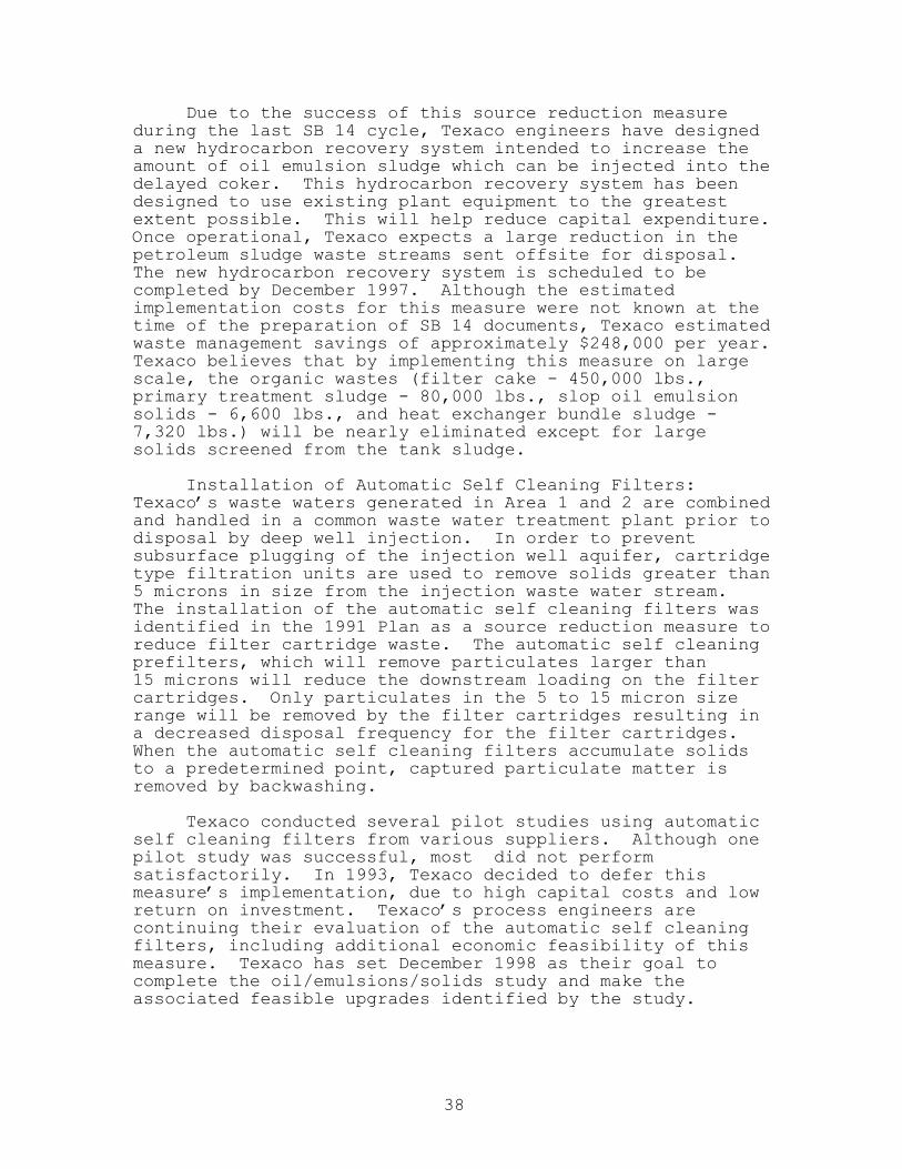
Due to the success of this source reduction measureduring the last SB 14 cycle, Texaco engineers have designeda new hydrocarbon recovery system intended to increase theamount of oil emulsion sludge which can be injected into thedelayed coker. This hydrocarbon recovery system has beendesigned to use existing plant equipment to the greatestextent possible. This will help reduce capital expenditure.Once operational, Texaco expects a large reduction in thepetroleum sludge waste streams sent offsite for disposal.The new hydrocarbon recovery system is scheduled to becompleted by December 1997. Although the estimatedimplementation costs for this measure were not known at thetime of the preparation of SB 14 documents, Texaco estimatedwaste management savings of approximately $248,000 per year.Texaco believes that by implementing this measure on largescale, the organic wastes (filter cake - 450,000 lbs.,primary treatment sludge - 80,000 lbs., slop oil emulsionsolids - 6,600 lbs., and heat exchanger bundle sludge -7,320 lbs.) will be nearly eliminated except for largesolids screened from the tank sludge.
Installation of Automatic Self Cleaning Filters:Texaco’s waste waters generated in Area 1 and 2 are combinedand handled in a common waste water treatment plant prior todisposal by deep well injection. In order to preventsubsurface plugging of the injection well aquifer, cartridgetype filtration units are used to remove solids greater than5 microns in size from the injection waste water stream.The installation of the automatic self cleaning filters wasidentified in the 1991 Plan as a source reduction measure toreduce filter cartridge waste. The automatic self cleaningprefilters, which will remove particulates larger than15 microns will reduce the downstream loading on the filtercartridges. Only particulates in the 5 to 15 micron sizerange will be removed by the filter cartridges resulting ina decreased disposal frequency for the filter cartridges.When the automatic self cleaning filters accumulate solidsto a predetermined point, captured particulate matter isremoved by backwashing.
Texaco conducted several pilot studies using automaticself cleaning filters from various suppliers. Although onepilot study was successful, most did not performsatisfactorily. In 1993, Texaco decided to defer thismeasure’s implementation, due to high capital costs and lowreturn on investment. Texaco’s process engineers arecontinuing their evaluation of the automatic self cleaningfilters, including additional economic feasibility of thismeasure. Texaco has set December 1998 as their goal tocomplete the oil/emulsions/solids study and make theassociated feasible upgrades identified by the study.
38

TEXACO, Wilmington:
Waste Water Sludge Reduction Using Circulating SamplePoints and Installation of Cyclonic Separator: Sewer sludgeis chiefly a result of unit pads wash down activity. Otheractivities and contaminants which contribute to sewer sludgeinclude heat exchanger bundle cleaning, pipe cleaning,boiler blowdown, waste lime slurry and coke fines. Theresiduals from washing unit pads and other washdownactivities, flow to the sewer system where sewer sludgeaccumulates over time. Texaco selected four sourcereduction measures. The following two are focused onreducing sewer sludge.
Texaco started using circulating sample points insteadof traditional sampling bibs to reduce the amount offlushing time and product loss needed before obtaining arepresentative sample. This decreases the amount of productdrained onto the unit pads and reduces the overall toxicityof the sewer sludge. Texaco spent $87,500 in capital costto install circulating sample points at thirty fivedifferent places throughout the plant. This allows for moretimely and accurate sampling but offers poor payback interms of waste management costs (less than $10,000 peryear).
Texaco used upstream cyclonic separators to assistgravity separators. This measure will reduce the amount offines that contribute to sewer sludge. Texaco estimated3,000 to 10,000 pounds reduction of sewer sludge handled bythe waste water treatment plant. The use of upstreamseparation enabled reuse of specific solid side streamswithin their process thus eliminating the combined wastesludge generated by the waste water treatment plant gravityseparator.
TOSCO REFINING COMPANY, Martinez:
Replace Sand with Absorbent: A key source ofgeneration of oil/water sludge is absorptive cleanup of oilysurfaces using sand. Sand remaining after physical removalusing a broom and shovel is washed down the sewer. Sandentering the sewer contributes to oil/water separationsludge solids. Tosco will replace sand with an absorbentmore easily swept from hard surfaces thus eliminating theneed for water cleanup. Diatamaceous earth and vermiculiteare two alternatives under consideration. Tosco will reducesludge by approximately 10 tons per year. There is nocapital cost involved. The cost savings of $31,850 per yearwill be realized with implementation of this measure. Arecurring cost of $1,000/year is estimated for purchase of
39

fresh absorbent and disposal of contaminated absorbent ashazardous waste. This recurring cost is currently spentusing the traditional sand absorbent.
Use of Lead Blankets For Covering Sewers: Anothersource of oil/water separation sludge is the use of a burlapcover topped with sand to close sewer openings duringmaintenance activities. Sand lost to the sewer when coversare removed contributes to the formation of oil/waterseparation sludge solids. Tosco is planning to cover seweropenings with lead blankets rather than burlap and sand.This is estimated to reduce sludge by 5.6 tons per year.Capital cost and payback period are estimated at $15,625based on the purchase of 125 lead blankets at $125 perblanket, and 1.2 years respectively.
ULTRAMAR, Wilmington Refinery:
Evaluate Potential Alkylation Waste Recycle Options:In recent years, Ultramar has attempted to establish arecycling program for the reduction of alkylation sludges.One alternative being considered is the potential use ofalkylation sludges as a fluxing substitute in metal refiningor as a raw material in the manufacturing of hydrofluoricacid. Ultramar will continue to evaluate this and otherrecycling alternatives in the hopes of developing a viablealkylation waste recycle program.
UNOCAL, Santa Maria Facility:
API Separator Sludge Reduction using the Delayed Coker:Unocal’s demonstrated current practice is to direct APIsludge to the delayed coking process and hence recover oilproduct. Unocal mentioned that the delayed coking processhas eliminated the need for the disposal of sludge andcurrently delayed coking is the best technical andeconomical method for handling this waste.
UNOCAL, Los Angeles Refinery, Carson Plant:
Evaluate Potential Spent Catalyst Recycle Options:Unocal uses six different types of catalysts throughout itsrefinery. One spent catalyst type is produced in thehydrotreating process. The remaining five spent catalystsare generated in the hydrogen plant. Unocal has twohydrotreaters. They remove metals, sulfur compounds, andsome nitrogen from gas oil feedstocks. Hydrotreating mustbe completed to remove sulfur from gas oil and to helpprevent deactivation of the catalyst used in other
40

downstream processes. Metals removed during thehydrotreating process deposit on the catalyst. The hydrogenplant uses a sulfur conversion catalyst, typically a cobaltmolybdenum catalyst. This is to convert all sulfurcompounds in the light gas feed streams to hydrogen sulfide.
Unocal will evaluate the sale/use of spenthydrotreating and spent steam reforming catalysts as a rawmaterial feed to an abrasive manufacturing facility. Itwill also evaluate sale/use of hydrogen plant spent catalystas a raw material feed to a primary smelting facility.There are no capital, operating or maintenance costsinvolved. Estimated source reduction benefit is expected tobe reduction of approximately 290,000 pounds of spenthydrotreating catalyst and 100,000 pounds of spent hydrogenplant catalyst annually.
Although not an SB 14 major waste stream but becausesignificant source reduction opportunities exist for thespent catalysts, Unocal actively pursued source reductionevaluation of this minor waste stream.
Tank Inventory Optimization Study: Tank bottom wastesare generated at Unocal throughout the various tanks used bythe refinery for storage of raw crude and various crude oilintermediate streams. Unocal generated approximately2,500 tons of tank bottom wastes in 1994. This waste streamaccounted for twenty seven percent of the total hazardouswaste generated at the site. Tank bottom wastes aregenerated when solids or semi-solid materials in the rawcrude or intermediate stream settle to the bottom of thestorage tanks. The material that accumulates in the tankbottoms is a combination of various heavy constituents.These heavy constituents include solids in the raw crude oilor intermediate stream, rust or scale from tanks, pipes, andother equipment, and heavy wax like paraffin hydrocarbons.
The above material accumulates over time since theconcentration of the solids in the stored materials is verylow. Many years pass before a tank is taken out of service.Tanks are taken out of service when the tank requiresrepairs or for routine inspection. Unocal recyclesessentially all refinery tank bottom wastes to the on sitecoker unit where the oil is recovered to produce hydrocarbonfuels and the solids are recovered as saleable coke.Residual water in the sludges serves as quench water,replacing some of the quench steam.
Unocal believes that its tank bottom waste couldpotentially be reduced or eliminated through two measures:1) reduce tank inventory at the refinery and 2) managesludges as an excluded recyclable material. Feasibility
41

studies for both options indicate further evaluation isessential to determine viability. Unocal will conduct atank inventory optimization study to determine the optimumtank needs for the refinery. It may also be possible toreduce tank sludges by using dedicated tanks to storespecific product types. Capital, operating and maintenancecosts are estimated to be zero; estimated source reductionbenefit is unknown at this point. Unocal mentioned that theonly barrier to implement this measure would be that itshould not affect existing processing capabilities orproduct quality.
UNOCAL, Los Angeles Plant, Wilmington Plant:
Evaluate/Implement Process Modification to ReduceStretford Sulfur Waste: Stretford waste is generated in thetail gas unit. Unocal uses a Beavon Stretford (Stretford)process. The Stretford Plant processes the sulfur recoveryplant off gases to recover residual sulfur compound. Thesulfur cake removed by the Stretford process containsresidual vanadium. This sulfur cake is not saleable aselemental sulfur due to its undesired structure as well asits vanadium impurities. The vanadium content classifiesthe sulfur cake as a non-RCRA hazardous waste. Thismaterial, according to the regulations, cannot currently besold for use in the fertilizer industry. Therefore, Unocalis currently sending it to a landfill for disposal.
Unocal is examining process modifications that will addheat exchange and evaporation capacity to the tail gas unitthus allowing additional cake washing to remove vanadium.This modification will make sulfur cake a saleable productto the fertilizer industry. The resultant sulfur will nolonger be classified as a hazardous waste due to vanadiumcontent. Capital, operating and maintenance costs per yearfor this project are $400,000, $100,000 and $4,000respectively. More than 1,500 tons per year of this wastewill be reduced.
Implement Tank Block Modifications: The refinery’soily process waters and oily stormwaters are treatedinitially at the waste water treatment plant by the APIseparator. The separator uses gravity and retention time toseparate and recover bulk amounts of oil from the processwater and stormwater collected in the refinery sewer system.Heavier solids contained in these waters are removed as asludge from the bottom of the separator. The waste waterthen flows to Unocal’s three dissolved air flotation units,where emulsified oil and some solids are removed through theaddition of flotation air and treatment chemicals. The keyto reducing the quantity of sludge and float is minimization
42
of solids entering the refinery sewer system. Solidssources to the refinery sewer system originate from solidspresent in the raw crude, solids from raw water, solids fromunpaved plant areas, solids entering the sewers duringturnaround activities, unit maintenance washdowns, andresidual solids on the unit pads from routine operations.
These source of solids to the oily process sewers willbe reduced by placing chad rock on the earthen tank blockfloors to impede solids entrainment to sewers. Thisapproach also includes installing paving and small bermsaround sewer openings in the tank blocks to impede solidsfrom entering the sewer. Unocal also plans to implementstormwater impoundment cleaning. Again, the source ofsolids to the oily process sewers will be reduced bycleaning dirt and debris from stormwater surfaceimpoundments prior to the rainy season. These solids couldpotentially enter the sewer when the stormwater is managedin the unsegregated sewer system. While capital andoperating costs of both these projects are zero, themaintenance cost is estimated at $30,000 per project peryear. Source reduction of the waste is estimated at200 tons annually per project.
UNOCAL, San Francisco Refinery:
Substitute Nickel-Based Catalyst for the CurrentCopper-Based Catalyst: Numerous refinery processes unitsuse catalysts, including the hydrocracker unit and itsassociated catalytic reformer and unisar units, the isomunits, and the steam power plant. Spent catalysts areperiodically removed from these process units during unitturnarounds and replaced with new or regenerated catalysts.
Unocal’s sulfur sorber reactor currently uses acopper-based catalyst. A nickel-based catalyst has beenidentified as having the potential to approximately doubleservice life for the unit from approximately 22 months to46 months. If successful, this catalyst substitution wouldachieve approximately 50% source reduction of the spentcatalyst waste stream originating at this particularreactor. Approximately 28 tons of spent catalyst iscurrently generated from this reactor during turnaround.
Unocal has already determined that this alternative istechnically feasible. Although the cost of the nickel-basedcatalyst is almost double the cost of copper-based catalyst,installation of the nickel-based catalyst would reduce thetotal catalyst replacement cost by 5 percent due to itslonger life.
43

Repair Heat Exchanger Leak: The low temperature shiftreactor currently uses copper- and zinc-based catalyst andhas historically achieved runtimes lasting approximatelyfour years. However, over the last four to six years,runtimes lasting only one to two years have been achieved.An operational problem has been identified that appears tobe the cause of these shortened runtimes; specifically aheat exchanger leak was found that, when combined with achanged chemical treatment of boiler water, may haveresulted in the preliminary deactivation of the catalyst.The heat exchanger leak was repaired at the most recent unitturnaround and should enable the reactor to again achievefour year runtimes.
Approximately 70 tons of spent catalyst is currentlygenerated from this particular reactor during turnaround.The reactor can again achieve four year runtimes, thereby50 percent to 75 percent source reduction of the portion ofthe spent catalyst waste stream originating from thisparticular reactor can be expected. Unocal engineersalready determined that this alternative was technicallyfeasible.
WITCO CORPORATION, Oildale Refinery:
The Witco’s oildale refinery, processes selected localcrude oils to produce a variety of hydrocarbon products suchas refined lubricating oil base stocks, finished lubricatingoils, asphalt, specialty oils and diesel fuel. Witco’s 1994SB 14 documents declared only one major hazardous wastestream: Tank bottoms. Approximately 500 tons of this wastewere generated in 1994. This waste stream contains onlyasphalt and lime. This tank bottom waste was generatedthrough the use of lime slurry to neutralize acids presentin the refinery crude oil feedstock. Acids must beneutralized to produce neutral or near neutral distillatesthat meet manufacturing specifications. An excess lime isthe traditional neutralizing treatment, and this creates thetank bottom waste stream.
Witco has developed a plan to reduce the excess limeusage, which in turn, reduces the quantity of asphalt tankbottom generated. The long range plan calls for notallowing unreacted lime to reach the distillation unit.This plan will use saturated lime water to react with theacid in the crude. The water will be separated from thecrude prior to crude entering the distillation unit and,after cleanup, is recycled back to be saturated with limemakeup and consequently redirected back to neutralize thecrude feedstock. The refinery’s conservative estimatesuggests that at least 95 percent reduction of this waste
44

can be achieved after 1994. This projection is based on therefinery’s laboratory and limited pilot plant experiments.Further pilot studies are needed to select proper equipmentfor full scale operation. An Economic evaluation indicatedthat the costs of designing and installation of the new fullsize equipment will be recovered in three to four years.
45
V. CASE STUDIES
The following section presents three case studies.Each was selected to describe in detail its pastachievements and future projections for hazardous wastereduction. These are beneficial measures that can beemployed generally at most refineries.
1. Unocal San Francisco Refinery
The Unocal San Francisco Refinery is located in Rodeo,Contra Costa County and has operated at the same locationfor the last 100 years. Unocal’s production at thisfacility includes butane, various grades of gasolines,diesel fuel, jet fuel, lubricating oils, fuel oils, waxes,sulfur, and petroleum coke. In order to produce thesespecific products, the refinery is designed to process twospecific types of crude oil: San Joaquin Valley Heavy crudeand Alaskan Cook Inlet Crude oil.
Unocal has several process units at its presentlocation. More than half of the currently operating processunits have been constructed since the early 1970s. A newcoking unit and a new crude distillation unit wereconstructed in the 1980s, and the addition of sludge cokingfacilities to the coking unit were completed in the early1990s. Unocal started its reformulated gasolines (CARBgasoline) construction project during early 1995, and wereplanning to complete in fall 1995.
Unocal’s 1995 Plan identified the following major wastestreams:
• Stretford solution• Tank bottoms• Spent catalyst• Stretford solids and• Oily trash
Unocal generated 6,080 tons and 5,800 tons of SB 14applicable nonaqueous hazardous waste during reporting year(1994) and baseline year (1990) respectively. Although itappears that Unocal increased its waste generation byapproximately 5 percent in the reporting year compared tothe baseline year, the refinery estimates that it hasactually achieved a source reduction of approximately 18.4percent between 1990 and 1994. This reduction is measuredby the ratio of the total quantity of major hazardous wastegenerated to total raw material throughput (i.e. totalquantity of major hazardous waste streams generatednormalized to production).
46

Unocal generated 420,000 tons and 355,000 tons ofSB 14/SB 1133 applicable aqueous waste during 1990 and 1994respectively, a reduction of 15 percent or 65,000 tons. Thepercent reduction would be greater if a normalization factorwas considered in this particular reduction calculation.
The following table provides a comparison of Unocal’smajor hazardous waste generation totals in 1990 and 1994:
Hazardous Waste Reduction Percentage
Generation Tons ChangeNonaqueous CWC 1990 1994 Percent
Stretford solution 132 3,842 3,620 5.8
Stretford solids 181 58 358 (517)
Spent catalyst 162 716 527 26.4
Oil/water sludges 222 616 5 99.2
Oily trash 223 56 333 (495)
Tank bottoms 241 30 997 (3223)
TOTAL (Major & Minor 5,800 6,080 (5) Waste Streams)
Aqueous
Phenolic sour water 132 241,100 236,600 2.1
Unicracker water 132 120,000 60,000 50.0
Steam pwr, plnt. water 132 60,000 60,000 0.0
TOTAL 421,100 356,600 15.0
Past Achievement - 1990 - 1994
Unocal identified six major waste streams for the 1990baseline year: Stretford solution, spent catalyst, oil/water separator sludge, phenolic stripped sour water,unicracker demineralizer regeneration water, and steam powerplant demineralizer regeneration water. All were identifiedas major streams for the 1994 reporting year, except foroil/water separator sludge. Three additional majorhazardous waste streams were added in the 1994 reportingyear: Stretford solids, oily trash, and tank bottoms.
47

The following section discusses the evaluation ofprogress made from 1990 to 1994 for reducing the nine wastestreams identified in the Unocal 1994 Hazardous WasteManagement Performance Report:
Stretford solution/Stretford solids (CWC 132/CWC 181)
These waste streams represent 65 percentage of thetotal hazardous waste streams generated in the currentreporting year. These are the most significant of Unocal1994 hazardous waste streams. Therefore, they have been thefocus of numerous source reduction and waste minimizationefforts over the last four years as discussed below:
• Startup of Verti-Press filters - Unocal observed thatthe heating of Stretford solution in autoclaves wascontributing to an accelerated rate of thiosulfateby-product formation, which in turn was necessitatingmore frequent purges of the Stretford solution than wasdesirable. In 1991, Unocal installed two Verti-Pressfilter units to replace Beavon-Stretford plantautoclaves. Although the filter presses have had minoroperational problems, in general, Unocal felt that thepresses have led to a significant net reduction in thegeneration of Stretford solution.
• Reslurry sulfur from filter presses to autoclaves -After startup of the ventri-press filters in 1991,Unocal attempted to reslurry sulfur from theverti-press filters cake with condensate and thenreturn the slurry to the autoclaves in order to meltthe recovered sulfur. Sulfur purified by melting has amuch greater value on the open market than sulfurfilter cake, which, due to low demand is usuallydisposed in the landfill. However, Unocal discontinuedthese attempts due to multiple operational problems,including getting the slurry into the sulfur pit,corrosion problems, and line plugging problems.
• Door sheets installation in the baffle of the oxidizertanks - Unocal installed doorsheets on two of the threeinternal baffle plates found in each of the threeStretford oxidizer tanks. Implementation of thisalternative facilitated the removal of Stretford solidsfrom the tanks during changeouts and had the net effectof increasing the quantity of Stretford solidsgenerated. However, it facilitated the cleaning of theoxidizer tanks, and therefore, resulted in a decreasein the quantity of Stretford-contaminated wash watergenerated, to an extent that more than offset theincrease in generated solids.
48

• Change from continuous batch purging - Unocal’sstandard practice was to purge Stratford solution on acontinuous basis. Up to 20,000 gallons of spentStretford solution per week (equivalent to a millionpounds per year) was continuously purged. Followingthe first 1993 quarter changeout, Unocal discontinuedcontinuous purging due to operational considerations.The units ran from first quarter of 1993 changeoutuntil the October 1994 changeout without any purges, a16 month batch run. During the October 1994 changeout,Unocal purged the entire inventory of Stratford units.This resulted in the generation of approximately350,000 gallons of spent Stretford solution. The neteffect of this change was to decrease the yearlygeneration rate of spent Stretford from a maximum ofapproximately one million gallons to a maximum ofabout 262,000 gallons, i.e. 350,000 gallons over16 months.
• Regeneration of Stretford solution using the GlobalSulfur Systems, Inc. Process - The Global process is aportable treatment process designed to extend the lifeof a given charge of Stretford solution by removingcontaminants such as thiosulfates from the Stretfordsolution prior to the contaminants’ accumulation toconcentrations that would render the solution spent.The Global process accomplishes this removal byconverting thiosulfates to sodium sulfates and thenremoving the sodium sulfates from solution.Implementation of the Global process alternative wouldtheoretically result in reduced hazardous wastegeneration rates by 50% or more, due to the extendedrun times that would be made possible for a givencharge of Stretford solution.
Unocal made an attempt during 1992 to implement theGlobal source reduction alternative. Unocalexperienced numerous operational difficulties andimplementation was stopped for reasons of technicalperformance and cost. Although the attempt toimplement the Global process in 1992 was unsuccessful,Unocal will evaluate this approach again, since theprocess has a potential to significantly source reduceUnocal’s largest hazardous waste stream.
In summary, the Stretford solution/Stretford solidsgeneration for 1990 and 1994 were 3,900 tons and 3,978 tonsrespectively, a two percent increase. Among other factorsdiscussed above, the greatest single factor influencingUnocal’s Stretford solution/solids waste generation ratesbetween 1990 and 1994 was the timing and scale of solutionchangeouts. The lowest quantity of Stretford was generated
49

during 1992 (2,750 tons), when the attempts at using theGlobal process took place, and before the major solutionchangeout occurred in the first quarter 1993. Total rawmaterial and total undiluted crude throughputs were alsoincreased by 12.2 percent and 10.6 percent respectively from1990 to 1994.
Spent Catalyst (CWC 162)
Numerous refinery process units use catalysts,including the hydrocracker unit, and its associatedcatalytic reformer and unisar units, the isom unit, etc.Spent catalysts are periodically removed from these processunits during unit turnarounds and replaced with new orregenerated catalysts. During 1990, Unocal generated spentcobalt/molybdenum, nickel/molybdenum, palladium, chromium/nickel, and copper/zinc based catalysts. Unocal manifestedall spent catalysts offsite as hazardous waste to metalrecycling/reclamation facilities. The offsite facilitieseither regenerated the spent catalysts or used leaching/chemical precipitation processes in order to reclaim metalsfrom the spent catalysts. The following discusses the twosource reduction measures used to manage this waste stream:
• Maximize process unit run length - The run length ofsome catalysts were increased during the 1991-1994period, resulting in the net effect of reducing thequantities of spent catalyst generated. The midbarrelunifier catalysts formerly had been changed out everynine months, but sufficient capacity was available toextend the run length to 24 months from 1993 to 1995.
Unocal generated 715 tons, 162 tons, 527 tons of spentcatalysts during 1990, 1991, and 1994 respectively. Theoverall trend in spent catalyst generation is generally oneof decrease.
Oil/Water separator sludges (CWC 222)
Implementation of one source reduction alternative, thesludge coking facilities, had the net effect of reducing theamount of oil/water separator sludge manifested offsite fordisposal by more than 99%-as cited by Unocal. Unocaltreatment/disposal data as offsite management of this wasteindicates that they managed 617 tons vs. only 5 tons of thisparticular waste in the 1990 baseline vs. the 1994 reportingyear. In 1994, 1,836 tons of oil/water sludges were used asfeedstock for the coker.
50

Unocal also implemented several programs during thisreporting period to prevent solids from entering the wastewater collection system which were cost effective andresulted in reducing the formation of sludges and the needto manage these sludges.
• Construction of sludge coking facilities at the delayedcoker - Test runs for the sludge coking facilities atUnocal were conducted in December 1990 and March 1991;the permanent facilities were placed into service onJuly 10, 1992. The sludge coking facilities enabledUnocal to process oil-bearing material concurrentlywith normal process streams in order to produce refinedpetroleum products. Previously these sludges werediscarded as wastes and included as tank bottoms andoil/water separator sludges.
The following is a listing of the projects Unocalsuccessfully implemented to prevent solids entering theirwaste water collection system: 1) street sweeping,2) construction of sediment catch basins/runoff trenchsystems for solids collection, 3) erosion control program,and 4) unit sweeping.
Unocal documented solids collection over the four yearreporting period which ranged from 19,700 pounds (in 1991)to 91,400 (in 1993) and averaged approximately 50,000 poundsannually. The actual amount of solids prevented fromentering the waste water collection system was greater, dueto non-documented solids collection efforts and to theunquantifiable effect of an erosion control programimplemented on an adjacent hillside and embankments. Thiseffort has likely captured solids at quantities at leastdouble the rate attributed to the documented efforts.Assuming each pound of solids entering the waste watercollection system gives rise to eight pounds of oil/waterseparator sludge, these solids control programs in theiraggregate likely prevented, on an annual basis, theformation of 800,000 pounds of oil/water separator sludge.
Tank Bottoms (CWC 241)
Unocal did not have any routinely scheduled tankcleaning activities in 1990. They cleaned only two tanks in1990 to perform repairs. Like oily trash, tank bottoms werenot a “SB 14 significant” waste stream during 1990 baselineyear. In order to comply with a new regulatory programstarting in 1992, Unocal cleaned a total of 15 tanksannually compared to the two cleaned in 1990. This had anet effect of increasing this waste category by more than3000 percent between 1990 and 1994.
51
• Construction of sludge coking facilities using tankbottoms - The sludge coking facilities can be used toprocess many oil-bearing materials, including tankbottoms. After successful test runs and securing apermit to operate, Unocal successfully processed morethan 95 percent of their tank bottoms as cokerfeedstock during 1994.
Phenolic stripped sour water (CWC 132)
Phenolic stripped sour water is classifiable ashazardous due to its selenium concentration of 5 mg/l.Unocal made attempts to implement the following threemeasures resulting in the reduction of 4,500 tons frombaseline to reporting year: 1) Selenium source controlstudy - several recycling measures were implemented tocontrol the volume of selenium laden waste water and toreduce water usage during the drought period in early1990’s. Approximately 10 gallons per minute (gpm) of thephenolic stripped sour water from the coking unit was beingrecycled as heater coil injection water. The phenolicstripped sour water was identified as having the highestselenium mass load at Unocal. All non-phenolic-strippedsour water was being recycled as either process wash wateror cooling tower make-up water. The reuse as cooling towermake-up resulted in a 10% to 20% removal of selenium acrossthe cooling tower system. 2) Treatment approaches usingunit #100 - in 1993, a temporary connection was installed atUnit 100 that allowed the phenolic stripped sour water to beintroduced upstream of the DAF unit, as opposed todownstream. The objective of the temporary connection wasto facilitate the evaluation of: a) potential seleniumremoval across the DAF unit, b) potential solids removalacross the DAF unit, and c) to test if the phenolic strippedsour water stream would assist in killing coliform bacteriawithin the DAF unit. The temporary connection had only beenused to facilitate waste water treatment evaluations and wasused only for one month at a time. and 3) Pilot study toevaluate new treatment processes - During 1995, Unocalstarted a pilot study to evaluate the use of ion exchangeresins for treating selenium-containing waste water. Theinitial results of the pilot study were being evaluated atthe time. Unocal planned to scale-up to full-scale plant,if the results were promising.
Unicracker demineralizer regeneration water (CWC 132)
Between the 1990 baseline and 1994 reporting years,Unocal reduced this waste stream by 60,000 tons (50percent). In the years following the 1994 reporting year,
52

Unocal expects to reduce this waste stream by more than95 percent. The success can be attributed to theinstallation of a reverse osmosis unit placed upstream ofion exchange units and an elementary neutralization tanklocated at the unicracker.
Some of the above measures are noteworthy in spite ofbeing treatment or recycling and not source reduction.SB 14 encourages generators to include in their 1995Reports, all types of measures including treatment andrecycling, implemented during 1990-1994 for their hazardouswaste reduction efforts.
Plan to Reduce Hazardous Waste During 1994-1998 and Beyond
The hazardous waste streams generated at Unocal in 1994were divided into two categories for the purpose ofdetermining the major hazardous waste streams: hazardousprocess (nonaqueous) waste, and hazardous industrial wastewaters (aqueous waste). A hazardous process waste definedas any solid, sludge, or liquid that was shipped(manifested) offsite for recycling, treatment, and/ordisposal or any solid or sludge that was managed onsitethrough recycling, treatment, or disposal. A hazardousindustrial waste water or aqueous waste is defined as anyhazardous liquid waste arising from a refining or otherindustrial process that was treated in Unocal’s industrialwaste water treatment plant and subsequently discharged toSan Pablo Bay under the conditions stated in Unocal’s NPDESPermit No. CA0005053.
Unocal generated a total of 6080 tons of nonaqueous,SB 14 applicable waste during 1994. This was comprised offive major SB 14 hazardous waste streams each constitutedmore than 5 percent of the total nonaqueous hazardous wastegenerated: Stretford solution (comprising 59.5 percent ofthe total hazardous process waste generated; Tank bottoms(16.4 percent); Spent catalyst (8.7 percent); Stretfordsolids (5.9 percent); and Oily trash (5.5 percent). Inaddition, three aqueous hazardous waste streams, thephenolic stripped sour water, unicracker demineralizerregeneration water, and steam power plant demineralizerwater. Each of these wastes comprised more than 5 percentof the total hazardous waste generated at Unocal during 1994(including both hazardous process wastes and industrialwaste waters) and thus were defined to be major wastestreams under SB 14. Aqueous and nonaqueous waste create atotal of eight major hazardous waste streams generated atUnocal during 1994.
53

Unocal identified and evaluated source reductionalternatives for these eight major waste streams and onenonmajor waste stream - oil/water separator sludges in 1994.The refinery identified 27 source reduction measures. Twowaste minimization alternatives were identified for the ninewaste streams using the following three SB 14 sourcereduction approaches: 1) operational improvements,2) production process changes, and 3) administrative steps.Six of these alternatives were rejected as infeasible. Theremaining 21 source reduction measures were selected andgiven high and low priorities. Ten priority measures wereidentified, and an implementation strategy for these higherranking measures was developed. Discussion of each selectedmeasure is beyond the scope of this assessment report,however, we encourage those who are interested, to reviewUnocal’s 1994 SB 14 documents. A listing of all twenty onesource reduction measures is contained in Appendix B. andexamples of source reduction selected measures’ abstractsare contained in Appendix E.
Unocal’s goals for reducing its major waste streams isvery ambitious. If the modified Global process sourcereduction alternative for Stretford waste streams can besuccessfully implemented, Unocal’s overall source reductiongoal for hazardous nonaqueous waste for the 1994 to 1998reporting period will be 43 percent. If the Global processimplementation proves either technically or economicallyinfeasible, Unocal’s overall source reduction goal for theperiod will be revised downwards to 15 percent. In terms ofweight reduction, 43 percent reduction amounts to an annualreduction of more than 2,600 tons of nonaqueous waste.
The total raw material throughput at Unocal increasedby 12.2 percent between 1990 and 1994. Due to newregulations Unocal implemented its aboveground tank cleaningand inspection program. If tank cleaning had not occurred,the major waste stream generation rate would have decreasedby approximately 8.2 percent between baseline and reportingyear. Combining the two factors, Unocal achieved sourcereduction of approximately 20.4 percent for its major wastestreams between 1990 and 1994.
2. ARCO Products Company
The ARCO Products Company is located in Los Angelesarea and was originally constructed as a part of the PanAmerican Oil company. Currently, it has a crude oilprocessing capacity of 245,000 barrels per day. Majorprocess units include three crude oil distillation units,two vacuum distillation units, a fluid catalytic cracking(FCC) unit, three reformers, two delayed cokers, a
54

hydrocracker, a hydrotreater, an alkylation plant, an MTBEunit and a sulfur tailgas recovery unit. The waste watertreatment plant operated at the refinery includes APIseparators and induced gas flotation units.
The products produced by ARCO include gasoline, jetfuel, diesel, sulfur, coke, propane, butane, fuel oil andcarbon dioxide.
The refinery generated nine SB 14 waste streams by CWCcode during 1994 totalling 1.337 million tons. One out ofnine wastes was a major aqueous waste stream and two weremajor nonaqueous wastes. They were: 1) waste water (CWC135) - 1.332 million tons 2) waste water sludges (CWC 222) -3,190 tons and 3) polymerization catalyst (CWC 161) -413 tons.
The refinery generated thirteen SB 14 nonaqueous wastestreams by CWC code during 1990 totaling 12,100 tons. Threeout of thirteen waste streams were major waste streams.They were: 1) Oil/water separator sludge - 9,626 tons(79.5 percent) 2) Oil containing waste (CWC 223) -1,327 tons (11 percent) and 3) Sand blast media (CWC 181) -667 tons (5.5 percent).
Comparison of major hazardous waste streams are as follows:
Nonaqueous:
1990 1994 ReductionWaste CWC tons tons Percentage
Polymerization* 161 290 413 (42)catalyst
Sandblast sand 181 667 20 97
Waste water sludge 222 9,626 3,189 67
Oil-containing 223 1,327 218 84waste
TOTAL (Major and Minor) 12,110 4,963 59 * not a major waste stream
Aqueous: 1990 1994 Reduction
Waste CWC tons tons Percentage
Waste water 135 9.158x10 1.332x10 85discharged to POTW
55
6 6

The following section describes the evaluation ofprogress made from 1990 to 1994 for the reduction achievedfor the four waste streams identified in the 1995 HazardousWaste Management Performance Report:
Polymerization catalyst (CWC 161) Generatedquantities of this hazardous waste increased by 43 percentfrom 1990 to 1994. The increase was attributed to a changein the method of spent catalyst removal from the reactors.In the past, spent catalyst was water blasted but at presentit is dry-drilled and chipped from reactor walls. The wetmethod resulted in losses of solids to the sewer becominghazardous waste water sludges.
Sandblast sand (CWC 181) The generation of hazardouswaste sandblast sand has been reduced by 97 percent. Thishas resulted from the use of alternative abrasive that didnot have high metal content. In addition, successfulefforts were undertaken to reduce the actual use of somesands. In 1995, Dewayne Reeher of maintenance departmentwon a $2,000 corporate stamp out waste award for hissuccessful efforts to reduce the use of hydrohone sand-agrit high in hazardous metals content.
Waste water sludges (CWC 222) Hazardous waste watersludges accounted for less than 7 million pounds generatedin 1994. This is a 67 percent reduction from the wastewater sludge generation rate in the 1990 baseline year.These sludges are formed from oil and solids that enter therefinery waste water system and are then removed during thetreatment of the waste water to meet POTW dischargestandards. This waste is comprised of 1) API separatorsludge 2) DAF float and 3) primary sludges. The refineryhas characterized these sludges and have identified thefollowing four major sources:
• Dirt from the refinery that enters the oily watersewer.
• Calcium salts from the refinery water supply thatprecipitates in the refinery waste water system.
• Dirt from the producing formation that enters therefinery with the crude oil.
• Heavy oil that becomes attached to the dirt andprecipitates in the oily water sewer.
In 1993 ARCO spent more than $100,000 to study sourcereduction options for waste water sludges. Due to thisstudy, several projects were implemented. Many projectswere also implemented from the selected measures selected in
56

the 1990 SB 14 Plan. The following is a partial list ofsuccessful projects implemented to reduce sludges:
• Increase street cleaning frequency.• Application of asphalt to unpaved areas.• Modify FCC catalytic polymerization dumping
procedure.• Reduce FCC catalyst fine losses.• Plantwide closed loop sampling system.• Modify tank basins for stormwater bypass.• Common cooling tower blowdown header.
ARCO selected six source reduction measures for theirthree major waste streams in 1994. The refinery’s numericalgoal for reducing the amount of hazardous waste generated is20 percent. The following summarizes each selectedmeasure’s detail to reduce hazardous waste during 1994-1998and beyond.
Polymerization catalyst (CWC 161):Measure: Begin Agricultural use of spent catalyticpolymerization catalyst.The catalytic polymerization unit converts propylene fromthe FCC unit into gasoline blending stock and commoditychemicals. This reaction occurs in ten vertical reactorsand is activated by a catalyst consisting of phosphoric acidon extruded silica-alumina pellets. This material is calledcat poly catalyst. Spent catalyst is removed from thereactors approximately eighty times per year. This spentcatalyst is non-RCRA hazardous waste due to its corrosivity.This corrosivity is due to its phosphoric acid content.
Phosphoric acid is widely used in agricultural andhorticultural applications. A project is underway to divertthis material from the landfill to useful product in theagricultural industry.
Oil/water separation sludge (CWC 222):Measure: Divert Cogeneration cooling tower blowdown to thecooling tower header.Calcium salts in the refinery water supply causes anincrease in the generation of waste water sludges. Whencooling tower blowdown enters the refinery waste watersystem the sludge formation increases due to the highconcentration of calcium salts resulting from evaporation.In 1991, the refinery installed a separate system whichsegregates refinery cooling tower blowdown from the processsewers. At the time of installation, the cooling toweroperated by the Watson Cogeneration Company was not includedin the project. The cooling tower blowdown diverted fromthe oily water sewers is combined with treated process wastewater in Tank 95 prior to discharge to the local POTW.
57

While the majority of the calcium precipitation in therefinery was eliminated by segregation, precipitation ofcalcium salt occurs in Tank 95, generating sludge. Thisprecipitation will be reduced when the Watson cooling towersystem is installed.
3. Ultramar
The Ultramar Refinery processes 100,000 barrels per day(BPD) at its Wilmington facility, southern california andproduces gasoline, low sulfur diesel, jet fuel, fuel oil,fuel-oil blending components, sulfur, propane, and fuel gas.Their Report was prepared for the 1994 reporting year, with1990 cited as the baseline year.
Ultramar’s 1995 Plan identified the following majorwaste streams:
• Stretford solution (CWC 135)• Alkylation sludge (CWC 181)• Oily Sewer and API sludges (CWC 222)• Spent Alumina catalyst (CWC 162)• Tank Bottom Sludge (CWC 241)• Fluid Catalytic Cracking (FCC) fines (CWC 161)
This refinery is equipped with two conventional crudeoil distillation units, a vacuum fractionator unit, twodelayed cokers, a fluid catalytic cracking (FCC) unit,reformer, hydrotreater, hydrorefiner, hydrogen fluoride (HF)alkylation unit, and a sulfur tail gas recovery unit. Therefinery also operates a waste water treatment process usingan oil/water separator and a dissolved air flotation/inducedair flotation (DAF/IAF) unit.
Ultramar’s primary product, finished gasoline,production in 1994 was approximately same as in 1990.However, the refinery’s overall hazardous waste generationdecreased to 1,660 tons during the reporting year 1994compared to 4,835 tons in the baseline year 1990. Thesetotals represent 66 percent reduction in the refinery’shazardous waste generation. In addition, approximately61 percent of the Ultramar’s 1994 hazardous waste generationwas recycled.
58

The following table provides a comparison of Ultramar’smajor hazardous waste generation totals from 1990 to 1994:
Hazardous Waste CWC Generation Tons Reduction 1990 1994 Percentage
Stretford solution 135 2,378 108 95
FCC fines 161 557 588 (5)
Spent alumina 162 325 155 52 catalyst
Alkylation sludge 181 671 411 39
Oily sewer and API 222 463 269 42 sludge
Tank bottom sludge 241 168 108 36
TOTAL (Major and Minor) 4,835 1,660 66 (Waste streams)
Past Achievements - 1900-1994
Overall four year hazardous waste reduction:3,175 tons.
Stretford solution reduction (CWC 135) Crude oilprocessed by the refinery contains contaminants such assulfur which must be removed prior to processing.Sulfur removed from the crude is carried by the mainrefinery amine system to the sulfur plant. The sulfurplant processes the sulfur compounds to elementalsulfur using a Stretford process. Consequently, theresidual gaseous sulfur from the sulfur plant isremoved by the tail gas treating unit (TGTU) to meetstringent environmental regulations. The circulatingtail gas solvent is “Stretford Solution” which containsvanadium. Over time, the Stretford solutionaccumulates thiosulfates which in effect reduces thesolution effectiveness. Spent Stretford solution is ahazardous waste due to vanadium contamination fromvanadium catalyst and from high alkalinity (pH > 12.5).
The installation of the new TGTU resulted in thereduction of Stretford solution by > 95 percent. In1992, Ultramar completed the construction of a new TGTUwhich replaced the refinery combined amine tail gastreater and Stretford unit, and at the same time itupgraded the refinery main amine system to process180 tons per day of sulfur. The new TGTU and Stretfordunit allow for increased high sulfur crude processingwhile maintaining strict compliance with sulfuremissions limitations. The old Stretford unit wasretained as a backup allowing the refinery to continueoperation (albeit at a reduced sulfur crude feed) whilethe TGTU is out of service.
59

Alkylation sludge reduction (CWC 181) Ultramarreduced alkylation sludge by 40 percent starting in1994. Byproducts of the alkylation unit process aretwo highly acidic streams that are neutralized withpotassium hydroxide (KOH). KOH is spent to potassiumfluoride (KF) which is reconverted to KOH using lime.The residual (alkylation sludge) is a precipitate,composed principally of calcium fluoride, which ismanaged as a hazardous waste.
Oil/Water separation sludge (CWC 222) A number ofrefinery oil-bearing sludges are separated at the wastewater treatment plant. These waste streams originateprimarily from process sewers and the tank cleaningoperations. Ultramar recycles these sludges back intoits delayed coking operation under license using thepatented Mobil oily sludge coking (MOSC) process. TheMOSC process uses process water mixed with oily sludgesas a partial substitute for quench water in the finalstage of the coking cycle. Oily sewer and API sludgeshave been recycled in Ultramar’s MOSC unit sinceNovember 1987. Implementation of this process haspractically eliminated generated waste water sludge byan annual amount of 460 tons.
Spent alumina catalyst (CWC 162) The refinery reducedspent catalyst by 52 percent, from a 1990 generation of325 tons to a 1994 quantity of 155 tons. In 1993,Ultramar entered into an agreement with suppliers totake the refinery spent catalysts from the Alkylationunit for reuse in the production of fresh aluminacatalyst. The suppliers could not handle spentcatalyst high volume and packaging. ThereforeUltramar’s recycling effort was only partiallysuccessful. Ultrmar investigated the feasibility ofusing all the spent catalysts as process feed to cementproduction. Since 1994, spent alumina catalysts havebeen recycled as process feed in cement kiln foundries.
60

VI. SUMMARY
1. Actual data based on the twenty four facilities coveredin the second review based on 1995 Performance Reports,the petroleum industry indicates that 32 percent of itsannual hazardous waste generation was reduced duringthe 1990-1994 period. This amounted to more than61,000 tons annually. The above data reflect allhazardous wastes except aqueous hazardous waste treatedin the onsite aqueous waste treatment plants. Withcurrent hazardous waste disposal costs for petroleumwaste ranging from $125 to $750 per ton, thesereductions are estimated to have saved the petroleumindustry $7.6 to $45.7 million annually.
For the initial documents prepared during the firstcycle (September 1991), many of the petroleum industrygenerators did not address aqueous waste streams intheir source reduction evaluation which were includedin their current 1995 documents. SB 1133 was enactedSeptember 5, 1991 and clarified the requirements forevaluating both aqueous and non aqueous waste streams.Therefore, comparison of 1990 and 1994 aqueous wastereduction is not feasible.
2. Based on our review of the latest documents (1995)produced under the Act the industry projects that itwill implement 122 measures during the 1994-1998 cycle.Based on review of the 1995 planning efforts, it isprojected that the industry nonaqueous hazardous wastereduction can achieve an additional 31 percent ofhazardous waste reduction over the next several years.This projection amounts 53,500 additional tons annuallyreduced over the 61,000 tons annual reduction achievedduring the initial SB 14 planning cycle (1990-1994).If fully achieved, this can result in an additionalannual savings of $6.7 to $40.1 million.
3. In 1994, the petroleum industry generated 16.7 milliontons of aqueous waste. It is estimated thatcollectively, the petroleum industry will reduceapproximately 2.0 percent or 0.34 million tons annuallyof hazardous aqueous waste during 1994 - 1998 andbeyond.
4. Oil/Water separator sludge was number one waste streamduring 1994 and it may remain number one in the futuretoo. In the previous cycle the industry selected 33measures to reduce this waste stream and in this secondcycle it selected 44 measures.
61

5. No extremely hazardous waste was generated during 1994.During first cycle two sites mentioned extremelyhazardous waste generation in 1991. Both eliminatedthese waste streams between 1991 and 1995.
62
APPENDIX - A
Refinery Operation Description
Refinery Operations
For the purpose of simplifying the presentation thisdiscussion on refinery operations has been divided into fourbasic categories: Fuel Production; By-Product Processing;Ancillary Operations and Waste Water Management. FuelProduction encompasses those operations which manufacturepetroleum products such as gasoline and coke. By-ProductProcessing covers refinery operations that convert usedmaterials and/or undesirable petroleum constituents intosalable or reusable end products. Ancillary Operationsinclude those activities that support refinery functions andrecover energy. Finally, Waste Water Management deals withthe treatment of refinery waste waters including therecovery of usable oil products from refinery waste waterstreams.
Petroleum Product Production
There are three basic raw materials used in the crudeoil refining process : crude oil; catalysts; and processchemicals. Heat, the final component in this process, isused to accelerate reactions, separate components, andreduce viscosity. Crude oil arrives at the refinery by shipor pipeline and is stored in tankage prior to processing.Initial separation of crude components occurs indistillation columns. Subsequently, materials recovered bydistillation are used as a fuel source in the refinery, orsent to other processes to generate useful products. Theprocesses used to produce salable petroleum products arediscussed in further details in the following sections.
Distillation
Distillation is the first process a barrel of crude oilencounters after it leaves the crude oil storage tanks inthe refinery. Crude oil consists of many misciblesubstances all with different boiling points. While it isvirtually impossible to separate each compound in crude oilindividually, the distillation process uses temperature andpressure control to effectively separate groups of compoundswith similar boiling points into unique mixtures.
63

Crude oil is initially heated and salts are removedprior to distillation. The first material to separate outfrom the crude oil mixture during distillation is the sour(hydrogen sulfide containing) gases. Sour gases are routedto refinery plants so that hydrogen sulfide can be separatedfrom fuel gases. Hydrogen sulfide does not have value as afuel source but is an important source of sulfur which canbe recovered for use in the refinery or for resale to otherindustries. The next fraction removed during distillationare propane and butane. These materials can be processedfurther and sold as liquefied petroleum gas (LPG), used asan in-plant fuel source or used to produce hydrogen or otherchemicals.
Continued fractionation in the distillation columnsyields gasoline, jet and diesel fuels. The lower boilingmaterials, gas oil and reduced crude, are the last materialsto separate and require additional processing to reachdesired endpoints. Reduced crude is used as feed materialin vacuum distillation columns (distillation under vacuumlowers the boiling point of the materials and easesseparation).
Hydrotreating
Hydrotreating is a catalytic process which useshydrogen to improve the stability of and remove impuritiesfrom distillation products. Impurities in crude oil such assulfur, nitrogen and metals must be removed to meet productspecifications and to prevent poisoning of catalysts used insome down stream processes. A potential negative sideeffect of hydrotreating is hydrocracking. Duringhydrocracking desirable hydrocarbons are broken up intopotentially unusable by-products.
Catalytic Reforming
Catalytic reforming employs catalysts to mediatereactions that boost the octane level of distillationproducts. During the process of catalytic reforming,hydrogen is produced for use in hydrotreating. Catalyticreforming encompasses four types of reactions:
1) Dehydrogenation of naphthene to produce aromatics.2) Dehydrocyclization of paraffins to naphthenes and
aromatics.3) Isomerization of naphthenes and paraffins to more
highly branched isomers.4) Cracking of naphthenes and paraffins to shorter
hydrocarbon chains.
64
The fourth reaction listed above is undesirable becauseit reduces yields, lowers hydrogen purity and consumeshydrogen.
Hydrocarbon Cracking
Hydrocarbon cracking is a process in which largemolecules are cleaved into smaller ones. This process canbe accomplished either thermally or catalytically resultingin maximization of salable products from crude oil.
During catalytic cracking of hydrocarbons, thecatalysts act to increase the yield of desirable productsand minimize the production of less useful materials, orallow cracking to occur at more favorable temperatures andpressures.
Thermal cracking, which occurs in the coker, is aprocess that is typically used to crack the heaviesthydrocarbons, the residuum. Coke, a hydrogen poor (carbonrich) by-product of thermal cracking is left over afterheating, is also sold as a fuel source.
By-Product Processing
During the petroleum product refining process,by-products are produced that have resale value or they maybe reused directly in refinery processes thus displacingnormal feed stocks. Some of these by-products, such ashydrogen sulfide which is used in sulfur production, arenatural constituents in crude oil that are removed to makethe products cleaner. By-product processing at the refineryis discussed in more detail below.
Sour Water/Gas Processing
One of the principal by-products of petroleum refiningis sour off-gases. Sour gases contain hydrogen sulfide, anoxious volatile compound, that is easily stripped fromcrude oil or partially refined products containing hydrogensulfide and may be transported to hydrogen sulfide (H
2S)
plants. The hydrogen sulfide plants effectively separatesour off-gases into “sweet” and “sour” fractions. “Sweet”gases containing low hydrogen sulfide levels are thentransported to the refinery fuel gas system while sour gasesare routed to Claus sulfur units for sulfur recovery(sometimes referred to as the Stretford Process). The Clausunits produce elemental sulfur.
65

Sour waters are also generated by many processes at therefinery. In addition to hydrogen sulfide, ammonia is alsopresent in sour waters. Sour water is first concentrated instripping towers and subsequently delivered to facilitiescapable of recovering the ammonia. During ammonia recovery,hydrogen sulfide is separated out and returned to the sulfurrecovery process.
Caustic and Acid
A critical chemical used in the oil refining process iscaustic soda. After being used in the production of jetfuel and light gasoline, the caustic soda, with entrainedcresols or naphthenes, is sold as a product. After leavingthe refinery, these materials are processed to create freshcaustic soda and to recover the cresols and naphthene.Spent sulfuric acid, used in alkylation and also to treatjet fuels, remains sufficiently concentrated, and it is soldtypically for off-site remanufacture as commercial acid.
Ancillary Operations
Ancillary refinery operations include power productionand process water purification. These operations do notdirectly result in a salable product; however, they aredesirable operations because they reduce costs, recoverenergy (power production), and provide softened water forrefinery processes.
Cogeneration
In the Cogeneration (Cogen) Plant refinery fuel gas,natural gas, and LPG are used to generate electricity fromturbines located on site and to fire boilers that producesteam. Steam is a critical in many refining processes andfor the generation of electricity.
Water Treatment
The water treatment system consists of thedemineralizing and softening municipal drinking water priorto use in refinery operations. Inorganic ions such assodium, calcium, magnesium, and chloride are removed fromdrinking water using exchange resins. The purified watercreated in this process extends the life of refineryequipment by reducing scale and eliminating compounds whichinterfere with the refinery processes.
66

Waste Water Management
Waste water treatment includes the physical andbiological purification of aqueous wastes. Part of thisprocess involves oil/water separation. This leads directlyto the recovery of oil and oil products from the refineryeffluent system. Waste water treatment facilities consistof both passive and active oil/solids separation, oilrecovery, biological waste water treatment, and biologicalsludge digestion. The collection of waste water isaccomplished using a parallel system of pipes designed tocarry different waste water materials as discussed below.This two tiered waste water collection system is referred toas the segregated and unsegregated drain system.
The segregated drainage system collects discharges fromrefinery operations producing process waste waters. Theunsegregated system is used to convey non-process wastewaters, such as cooling tower blow down, and rainwaterrunoff. The parallel systems join after passing throughtheir respective treatment facilities and ultimatelydischarges to a POTW operating under the National PollutantDischarge Elimination System permit program and its strictpollution control limits.
Passive oil/solids separation is a process common toboth the segregated and unsegregated systems. Separation isaccomplished by transmitting waste waters through an oil/solids separator where materials are removed from the waterbased on their differing densities. Oils, which float onwater, are recovered from this process and the settleablesolids are periodically removed from the separator bottom.
Active oil separation processes are also employed onboth the segregated and unsegregated systems. Theseprocesses include dissolved and induced air flotation (DAFand IAF respectively) units. Oil removal by the DAF unitoccurs down stream of passive oil separation in thesegregated system. An IAF is used to polish unsegregatedsystem flow, including runoff.
The biological waste water treatment plant takes allwaste water flow from the segregated drainage system. Thisfacility consists of an activated sludge process for theremoval of dissolved organic material. Subsequent tobiological processing, solids generated during biologicaltreatment are removed by settling in clarifiers. Themajority of the settled material, which consists ofbiological matter, is recirculated to the process tomaintain aerobic (oxygenated) biological treatment activity.The balance of this separated biological solid is processedin the sludge digester.
67

Sludge digestion is an anaerobic process (biologicaltreatment occurs without oxygen) that reduces the mass ofbiological solids. Digested sludge is ultimately disposedof to the sanitary sewer or sent for dewatering and disposalto drying beds or by other means.
Throughout the waste water treatment process, oilrecovery is a preference to extract usable crude oil andrefined or partially refined petroleum products from liquidand solid materials. Using a two-tiered approach, liquidmaterials are transported to tanks and allowed to passivelyseparate. Recoverable oil is removed after passiveseparation and returned to the refining process. Solid andsemi-solid secondary materials generated in the waste watertreatment process are processed to recover trapped oil viaMOSC or another alternative such as mechanical separation.
68

APPENDIX - B
List of Selected Source Reduction Measures
The following is a summary listing of source reductionmeasures selected by the petroleum industry. Many of themeasures have been discussed in detail in the “SourceReduction Measures” section of this report. Some non sourcereduction measures have been also included in the following,if their implementation have broadly applicable beneficialenvironment effect.
Measure CWC
ARCO, Los Angeles
1. Divert stormwater to Dominguez Channel 1352. Divert cooling tower blowdown to Channel 1353. Train Personnel to avoid discharging benzene 135
to the sewer4. ARCO’s Stamp Out Waste program 1355. Divert Cogen cooling tower blowdown to the 222
cooling tower header6. Send cat poly acid for agricultural use 161
CalResources, Bakersfield
1. Request DTSC not to consider refractory waste 181as non-routine waste and hence exempt from SB 14
Chevron, Richmond
1. Screen out the inert ceramic support spheres 162from the spent catalyst and reuse the spheres
2. Install vegetative cover to hills and barren 222areas to reduce erosion
3. Eliminate use of sand bags to avoid particulates 2224. Improve the sludge removal process 2225. Regenerate bauxite filter media off-site 2226. Modify recovered oil system procedures 222
to minimize solids to the crude unit7. Use a street sweeper to remove soils 222
from streets and process areas8. Cover bare soil areas in pipeways 222
69

Measure CWC
Chevron, Bakersfield
1. Modify existing decision-making process 1812. Phase out use of cellar boards 2233. Waste segregation 2234. Personnel training 2235. Survey/Audit improved tank cleaning procedures 2416. Survey/Audit chemical products and mechanical 241
processes for improved oil, water, and solidsseparation
7. Survey improved sand control procedures 2418. Use of environmental friendly paints 1819. Decrease frequency of painting 181
Chevron, El Segundo
1. Continue using MOSC system and lobby U.S. EPA 222 to prove system’s legitimacy2. Institute routine drain line inspection 222
and maintenance program3. Install a heat exchanger on rec. oil system 2224. Coat tanks for longer service life 2415. Lobby for legal asphalt incorp. of 241
non-RCRA tank bottoms6. Recycle metals catalyst (not a source reduction) 162
Exxon, Benicia
1. Improved handling of ESP fines 2222. Modify desalter 2223. Optimize chemical usage at desalter 222
GATX Tank Storage, Carson
1. Repair tank roofs 2212. Improve housekeeping and maintenance 223
practices at loading racks3. Additional employee training 2214. Install additional sumps and 223
sloping tank bottoms5. Manage oil from pressure relief valves as a 221
non-waste material
70

Measure CWC
Huntway, Benicia/Wilmington
1. Pave the tank farm access road 2222. Reduce the sludge volume through centrifugation 3433. Isolate WORT conveyances from storm 222
water run-on4. Install closed loop water recycling units 343
on Vacuum and Seifer Mill water cooling system
Mobil Oil, Torrance
1. Reduce particulates into vacuum truck 222washout sump
2. Reduce truck wash out frequency 2223. Segregate hazardous and non-hazardous 222
truck services4. Eliminate vacuum truck washout sump 2225. Improved tracking of vacuum truck 222
washout area usage6. Addition of bio-filtration unit 3527. Segregate hazardous and non-hazardous waste 3528. Analyze and re-categorize other wastes 352
contributing to the total generation of CWC 3529. Improve CARB gasoline production process 134
Pacific Refinery, Hercules
1. Convert API to CPI oil separator to enhance 222oil/water separation
2. Install close loop sampling ports 222throughout process units
3. Establish new procedures for tank filling flange 611maintenance and sump level measurement
4. Implement new spill prevention procedures 352
Paramount Petroleum, Paramount
1. Use filter press to recover oil 2222. Participate in EPA Merit source reduction program 2223. Recharter in-house Hazardous Waste Committee 2224. Employee awareness training 222
Powerine Oil, Santa Fe Springs
None (Facility closing)
71
Measure CWC
Shell, Carson
1. Improve maintenance of roof drains 3522. Optimize cleaning water temperature 1813. Reuse liquid for water conservation and to reduce 181
waste water4. Train plant and contractor employees 1815. Maintain records of contractors waste
source reduction performance6. Provide incentives to employees7. Remove dry solids from surfaces 181
draining into separator8. Reduce product loss during tank water draws9. Reduce hydrocarbon spills and leaks 181
in pump pad area10. Reduce product loss in truck loading area 18111. Improve equipment maintenance12. Improve separator maintenance13. Use separator standing water to conserve fresh water14. Keep records of truck loading area spills
Shell, Martinez
1. Coat, gunite and curb to reduce sludge formation 2222. Reduce oil entry into sewer system at 222
sample stations3. Segregate high salts waters to biotreater 2224. Institute street sweeping program 2225. Relocate sand pile to avoid 222
particulate contamination6. Reduce high solids input streams 2237. Return low solids streams to processes 2238. Segregate hazardous waste and nonhazardous waste
Texaco, Bakersfield Plant, 1 and 2
1. Install automatic self cleaning filters 2232. Install hydrocarbon recovery unit 352
Texaco Bakersfield, Plant 3
Same as Texaco Plant, 1 and 2
72

Measure CWC
Texaco, Los Angeles
1. Improve unit housekeeping and pave areas 222around the sewers
2. Implement local/Internal waste reduction program
3. Change sample bibs at circulating sample points 2224. Use cyclonic precipitators to replace 222
gravity separation
Tosco, Martinez
1. Improve segregation of catalyst support 162materials from spent catalyst
2. Reclaim spent catalyst 1623. Recycle oily solids using the coker 2224. Segregate nonhazardous from hazardous oily waste5. Use recyclable/reusable absorbent6. Replace demineralizer system with reverse 222
osmosis system
Ultramar, Wilmington
1. Offsite recycling of spent catalysts 162and FCC fines
Unocal, Santa Maria
1. Recover oil through delayed coking
Unocal, Carson
1. Evaluate spent hydrogen plant catalyst use 162as feed to primary smelting facility
2. Implement tank inventory optimization study 2413. Tank bottom waste management as excluded 241
recyclable material4. Evaluate spent hydrotreating catalyst sale/use 162
as feed to abrasive manufacturing process
Unocal, Wilmington1. Implement tank farm modifications 2222. Implement stormwater impoundment and 222
maintenance program3. Evaluate sale/use of spent catalyst to an 162
abrasive manufacturing facility4. Evaluate spent hydrogen plant catalyst use 162
as feed to a primary smelting facility5. Evaluate Stretford sulfur washing 441
73

Measure CWC
Unocal, San Francisco
1. Substitute a nickel-based catalyst for current 162zinc-based catalyst in the sulfur sorber reactor
2. Improve operations of the two Verti-Press filters 1813. Implement modified Global Sulfur Systems Process 1814. Increase evaporative capacity in 132
mini cooling tower5. Increase conversion of H2S into elemental sulfur 132
in the upstream Claus units6. Substitute Unisulf (thiocyanate process 181
for existing Stretford process7. Investigate Dow process for recovering 132
anthraquinone disulfonic acid (ADA) andvanadium from Stretford solution
8. Substitute other liquid redox processes such as 181Sulferox, Locat, Sulfolin, or Hiperion processesfor the Stretford process
9. Investigate RUST process for removing vanadium 132from Stretford solution and/or dilute Stretfordcontaminated washwaters (Waste Minimization)
10. Ship Stretford solution to Cri-Met facility in 181Louisiana for vanadium recycling/reclamationinstead of to Dupont facility in New Jersey fortreatment/disposal (Waste Minimization)
11. Fix heat exchanger leak at low temperature 162shift reactor
12. Improve mixing operations for tanks 132#F101 and/or #F501
13. Lengthen unit runtime of one of the 162hydrocracking reactors
14. Evaluate economic feasibility of solids 222control by evaluating each of the following andsubsequently implement those methodologiesfound feasible: A) connecting roof drains tosewer basins, B) construct sediment traps aroundtank block drains, C) construct risers/weirsaround tank block drains, D) Install sedimenttraps within tank block drains, and E) Pave oroil tank block sediments
74
Measure CWC
15. Evaluate economic feasibility of solids 222control in the non-tank areas of the refineryusing the following five existing Unocalmethodologies. Optimize the existing programsby implementing the economically feasiblemodifications, and develop a system fordocumenting the quantities of solidscollected/prevented from entering the washwatercollection system a) construction of additionalsediment catch basins and/or runoff trenchesb) maintenance of sediment catch basins, pipetrenches, and other drainage structuresc) street sweeping program d) unit vacuumingprogram e) erosion control program (pave surfaces, oilsurfaces, plant vegetation control)
16. Repair bottom rakes on coke oil separator 22217. Evaluate tank filling and cleaning 222
procedures to determine if discharge ofoil to waste water treatment system canbe reduced, for instance, by using detectorsto reduce oil drainage during tank draws
18. Discharge non-hazardous cooling tower 222blowdowns to salt water discharge systeminstead of to waste water treatment system
19. Optimize handling and management of oily 223trash compounds at unit 220 equipment pad
20. Evaluate administrative measures to 223segregate non-hazardous compounds fromoily trash waste system
21. Redirect employee hazardous waste 223training to address specific componentsof the oily trash waste stream thatoffers source reduction opportunities
22. Evaluate methods for reducing the 223quantities of iron scale found withthe tank bottoms
23. Coordinate the tank cleaning planning 223process with the “Sludge Injection Committee”planning process
Witco, Oildale Refinery, Oildale
1. Reduce tank bottoms by reducing amount ofexcess lime
75

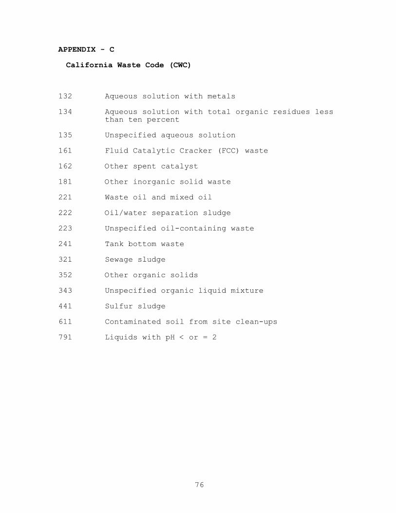
APPENDIX - C
California Waste Code (CWC)
132 Aqueous solution with metals
134 Aqueous solution with total organic residues lessthan ten percent
135 Unspecified aqueous solution
161 Fluid Catalytic Cracker (FCC) waste
162 Other spent catalyst
181 Other inorganic solid waste
221 Waste oil and mixed oil
222 Oil/water separation sludge
223 Unspecified oil-containing waste
241 Tank bottom waste
321 Sewage sludge
352 Other organic solids
343 Unspecified organic liquid mixture
441 Sulfur sludge
611 Contaminated soil from site clean-ups
791 Liquids with pH < or = 2
76
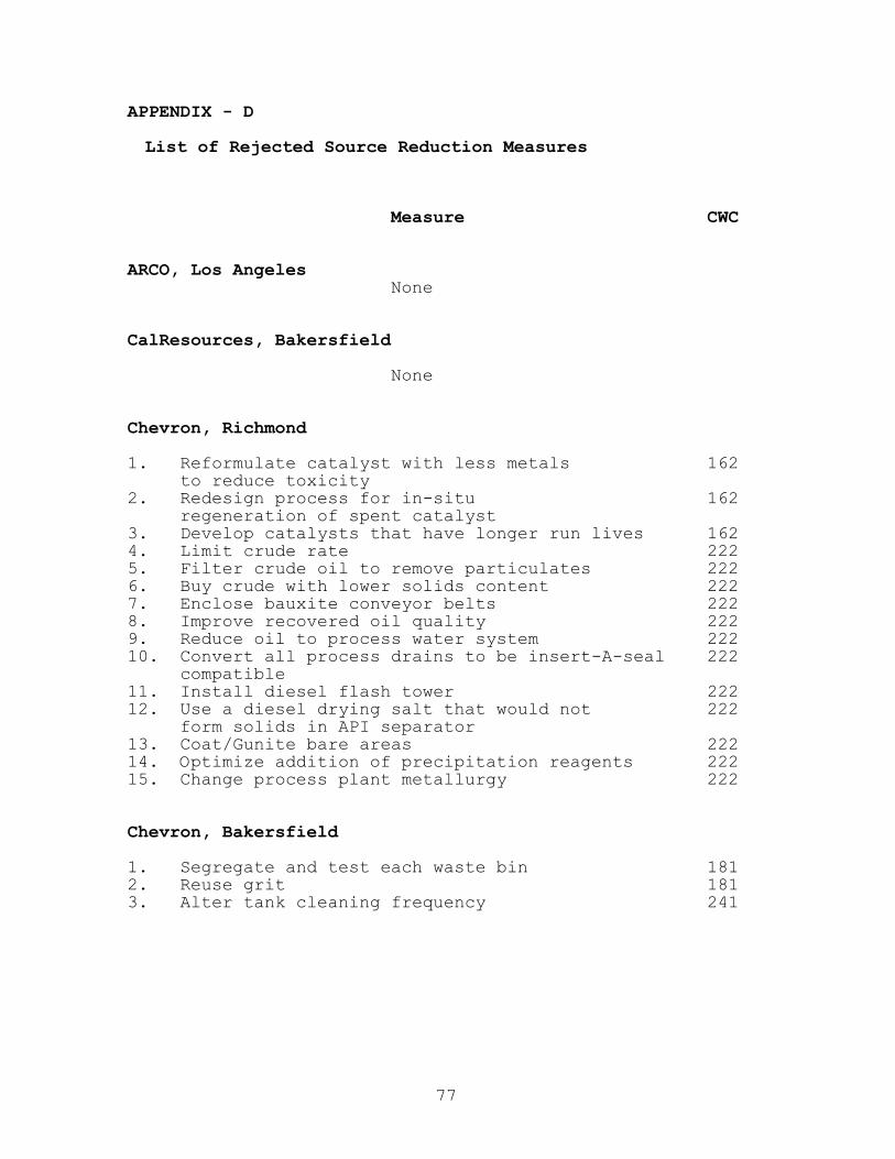
APPENDIX - D
List of Rejected Source Reduction Measures
Measure CWC
ARCO, Los AngelesNone
CalResources, Bakersfield
None
Chevron, Richmond
1. Reformulate catalyst with less metals 162to reduce toxicity
2. Redesign process for in-situ 162regeneration of spent catalyst
3. Develop catalysts that have longer run lives 1624. Limit crude rate 2225. Filter crude oil to remove particulates 2226. Buy crude with lower solids content 2227. Enclose bauxite conveyor belts 2228. Improve recovered oil quality 2229. Reduce oil to process water system 22210. Convert all process drains to be insert-A-seal 222
compatible11. Install diesel flash tower 22212. Use a diesel drying salt that would not 222
form solids in API separator13. Coat/Gunite bare areas 22214. Optimize addition of precipitation reagents 22215. Change process plant metallurgy 222
Chevron, Bakersfield
1. Segregate and test each waste bin 1812. Reuse grit 1813. Alter tank cleaning frequency 241
77

Measure CWC
Chevron, El Segundo
1. Replace centrifugal pumps at No. 2, 3, and 4 222separators with low shear pumps
2. Upgrade No. 4 separator 2223. Use street sweeper to clean roads 2224. Reduce inventory of oil and products resulting 241
in reduction of the number of storage tanksin service
5. Use different catalyst 1626. Control feed quality to catalyst reactors 162
Exxon, Benicia
1. Reduce solids in crude feed to the refinery 2222. Pave tank farm diked areas 2223. Remove biological oxidation solids 2224. Minimize water content of sludges 222
GATX Tank Storage, Carson
1. Treat, store and reuse pipeline hydrotest water 2212. Cover loading racks 2213. Cover manifold drains 2214. Recover product and reuse wash water 221
Huntway, Benicia/Wilmington
1. Install screens at WORT conveyance system’s 222opening and entrances
2. Use treated water for irrigation purposes 3433. Install new crude oil suction lines 222
on crude oil storage tanks4. Install automatic shut-off valves 222
on crude oil and product storage tanks5. Install a tank and pumpback system 222
to recover oily wastes from laboratory sinks
Mobil Oil, Torrance
1. Change pipe and equipment composition to control 352corrosion for scale and solids reduction
2. Change fluid composition in pipe to reduce scale 3523. Use corrosion inhibitors and anti fouling agents 3524. Stop or reduce water flow to groundwater
carbon bed 3525. Run carbon bed to avoid generation 352
of spent carbon6. Stop input of hazardous material to process sewer 134
78

Measure CWC
Pacific Refinery, Hercules
1. Replace crude oil feed with lower solid content 2222. Develop procedures to reduce solids from 222
heat exchanger bundle and catalyst fines3. Use street sweeper to remove dust and dirt 222
Paramount Petroleum, Paramount
None
Powerine Oil, Santa Fe Springs
None
Shell, Carson
1. Improve filtration of incoming product 1812. Optimize concentration of stored-product 181
additives3. Recirculate tank bottoms 1814. Install sloping, secondary bottom 181
in product tanks5. Use steam and detergent to clean tanks 1816. Optimize cleaning water temperature 1817. Optimize cleaning water pressure 181
Shell, Martinez
None
Texaco, Bakersfield Plant, 1 and 2
None
Texaco Bakersfield, Plant 3
None
79

Measure CWC
Texaco, Los Angeles
1. Pave entire refinery 3212. Use sandbags around sewer entrances 3213. Implement wipe out waste (WOW) program 3214. Reduce cooling tower blowdown frequency 2225. Reduce boiler blowdown by using demineralized 222
boiler feedwater 2226. Soften cooling water make-up 2227. Use reverse osmosis process for boiler feedwater 222
Tosco, Martinez
1. Pave refinery pipeways 222
Ultramar, Wilmington
None
Unocal, Santa Maria
None
Unocal, Carson
1. Change refinery crude feed to lower sulfur 162content
2. Redesign fresh catalyst 1623. Install partial oxidation hydrogen plant 1624. Reduce crude supply solids 2225. Pave additional areas 2226. Provide groundcover 2227. Install process sewer opening filtration system 2228. Install desalter filtration system 2229. Reduce crude supply solids 24110. Implement crude polymer injection 24111. Implement tank sludge polymer injection 241
80
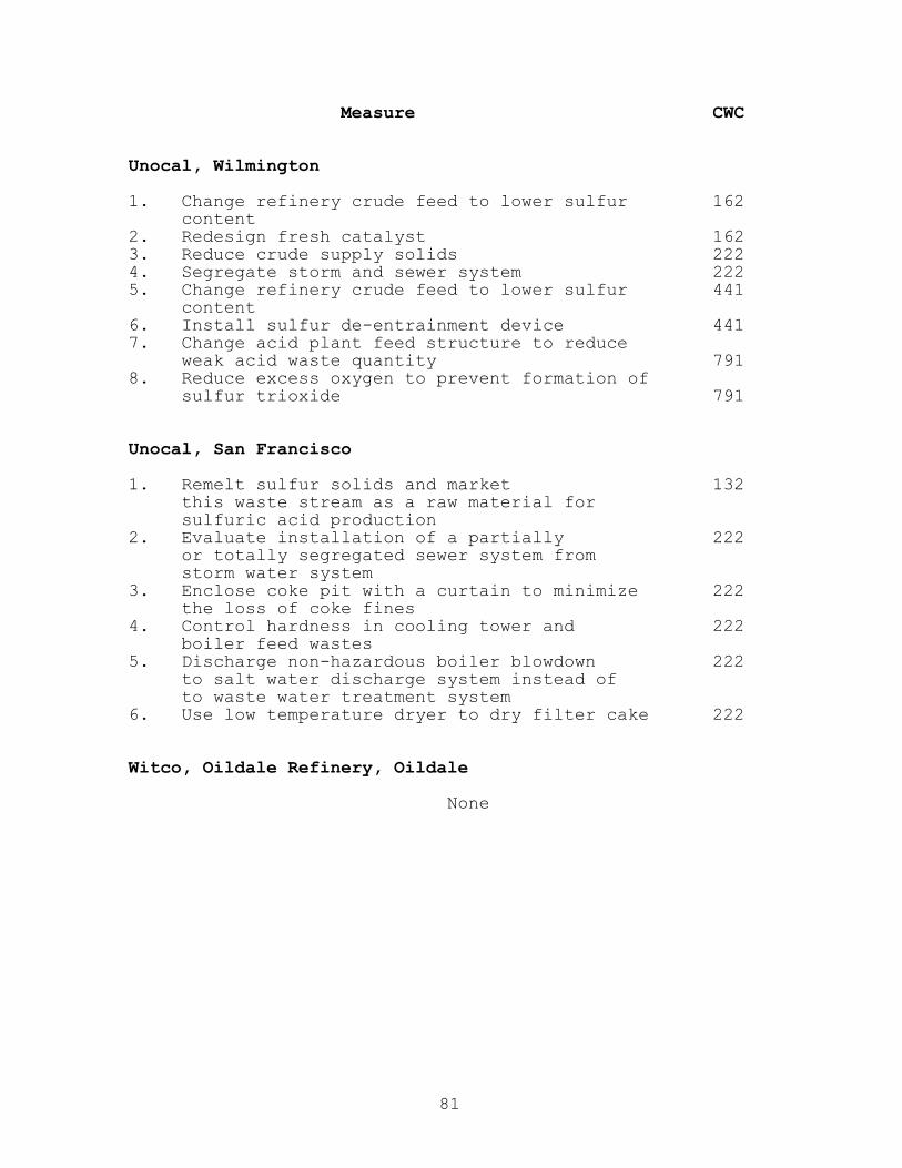
Measure CWC
Unocal, Wilmington
1. Change refinery crude feed to lower sulfur 162content
2. Redesign fresh catalyst 1623. Reduce crude supply solids 2224. Segregate storm and sewer system 2225. Change refinery crude feed to lower sulfur 441
content6. Install sulfur de-entrainment device 4417. Change acid plant feed structure to reduce
weak acid waste quantity 7918. Reduce excess oxygen to prevent formation of
sulfur trioxide 791
Unocal, San Francisco
1. Remelt sulfur solids and market 132this waste stream as a raw material forsulfuric acid production
2. Evaluate installation of a partially 222or totally segregated sewer system fromstorm water system
3. Enclose coke pit with a curtain to minimize 222the loss of coke fines
4. Control hardness in cooling tower and 222boiler feed wastes
5. Discharge non-hazardous boiler blowdown 222to salt water discharge system instead ofto waste water treatment system
6. Use low temperature dryer to dry filter cake 222
Witco, Oildale Refinery, Oildale
None
81

APPENDIX - E
Selected Source Reduction Measure Abstract - Examples
The following three abstracts are taken from Unocal,San Francisco refinery 1994 Source Reduction Plan. They allare comprehensive, providing detail of three selected sourcereduction measures seven criteria such as technicalfeasibility, effect on product quality, economic evaluation(feasibility), to name a few. They also detail otherpertinent information such as waste stream ID by CWC code,quantities generated in reporting year, process or activitygenerating the waste, measure description, type ofalternative, and expected change in hazardous wastegeneration. They provide cost savings and net benefitderive by implementing the measures.
Selected Source Reduction Measure Abstract - 1
Waste Stream ID: Oil/Water Separator SludgeCWC: 222
Quantity of Waste 5 tons were manifested off site forGenerated, 1994 treatment/disposal.
(1,836 tons were reused on site atthe sludge coking unit)
Process or Activity Oil/Water separator sludges areGenerating the Waste: generated at Unit 100, the Unocal
waste water treatment plant.
Measure Description: Evaluate the economic feasibilityof installing solids controlmeasures in the non-tank blockareas using any or all of thefollowing five existing Unocalmethodologies listed below;optimize existing programs byimplementing those measures foundeconomically feasible, and developa system for documenting thereduced quantities of solidsentering the waste water collectionsystem:
1. Construction of additionalsediment catch basins and/orrunoff trenches;
82

2. Maintain sediment catchbasins, pipe trenches, andother drainage structures;
3. Implement a street sweepingprogram;
4. Implement a unit vacuumingprogram; and
5. Implement an erosion controlprogram (pave surfaces, oilsurfaces, and plantvegetation).
During the 1990 to 1994 reportingperiod, all of the above fivesolids control methodologies wereused at Unocal: a street sweepingprogram was implemented beginningin 1990, a unit vacuuming programwas implemented in 1992, catchbasins and/or runoff trenches wereconstructed at 16 separatelocations. Sediments werecollected from these locations, andan aggressive erosion controlprogram was implemented beginningin 1992. This alternative willassess which solids controlprograms are economically viablebased on the current sludgemanagement techniques, and resultin the implementation andoptimization of a comprehensivesolids collection program.
Type of Alternative: Operational ImprovementExpected Change in Studies conducted by the AmericanHazardous Waste Petroleum Institute haveGeneration: demonstrated that for every pound
of suspended solids that enters thetypical refinery waste watercollection system, seven to ninepounds of oily sludge is generated,which can result in approximatelytwo to three pounds of deoiled,dewatered sludge. Implementationof these methodologies have reducedthe amount of oil/water separatorsludge generated by reducing thesolids loading to the waste watertreatment system. Optimization ofthe identified economically viablemethodologies would further reducethe sludge generation rate.
83

Technical Feasibility: All of the above methodologies haveproven to be technically feasibleand have been implemented atUnocal. This alternative involvesan evaluation of thesemethodologies for modificationswhich are found to be bothtechnically feasible andcost-effective, based on currentsludge management techniques.
Economic Feasibility: The cost savings realized from theimplementation of any of theidentified economically viablemethodologies would result in thereduction in cost to handle andtransport these sludges from thewaste water treatment plant to thecoker unit for recovery. The costof handling and transporting theoil/water separator sludges to thecoker is approximately $1.20 perbbl of sludge, determined on a wetweight basis. Assuming that thedensity of the sludge is 10 lbs./gallon, the handling andtransportation cost isapproximately $5.60 per ton ofsludge. This cost only accountsfor sludge handling andtransportation from Unit 100(separators and sludge filtrationprocess) to the coker unit; it doesnot account for the operation andmaintenance of the Unit 100 sludgetankage.
As a result, the cost of handlingthe oil/water separator sludges tothe coker unit, based on the amountof solids entering the waste watersystem, is approximately$5.60 x 8 = $45 per ton of solids.
The potential cost saving byreducing the amount of sludgehandling will be evaluated againstthe cost and effectiveness ofimplementing any of all of thesolids control methodologies.Maintenance and cost data for eachof these methodologies were
84

reviewed. For example, the catchbasin and storm basin maintenanceprogram led to the collection ofapproximately 180 tons of solidsfrom the period January to August1993, at a cost of approximately$19,000, or about $105 per ton ofcollected solids. The streetsweeping program led to thecollection of approximately 100tons of solids from the periodApril 1990 to May 1994, at a costof $40,000, or about $400 per tonof collected solids. The unitvacuuming program led to thecollection of approximately 3.2tons of solids in September 1992,at a cost of $5,600, or about$1,750 per ton of collected solids.
As a result, the costs for all ofthe solids control methodologiesappear to outweigh the cost tohandle and transport the oil/waterseparator sludges from Unit 100 tothe coker, following the successfulimplementation of the sludge cokingfacilities. However, the costsshown for handling/transporting thesludges to Unit 200 do not accountfor the costs that will benecessary to handle/manage thesludge quantities currentlyaccumulating in the Unit 100influent tanks. Unocal shouldinvestigate modifications to thesemethodologies to reduce solidscontrol cost and to increase thequantities of solids collected; ifsuch modifications cannot be cost-effectively made, these solidscontrol programs should bediscontinued.
Effect on ProductQuality: None expected.
Employee Health and No change from current health andSafety Implications: safety concern.
Permit/VarianceRequired: None.
Releases/Discharges: None expected.
85

Selected Source Reduction Measure Abstract - 2
Waste Stream ID: Stretford Solution/Stretford SolidsCWC: 132/181
Quantity of Waste 3,620 tons of Stretford SolutionGenerated, 1994: 358 tons of Stretford solids
Process or Activity Maintenance changeouts of StretfordGenerating the Waste: process vessels and tanks.
Measure Description: Implement Modified Global Process:
The Global process is a portabletreatment process designed toregenerate spent Stretford solutionby converting sodium thiosulfate tosodium sulfate and then removingthe sodium sulfate from solution.This process effectively extendsthe life of the Stretford Solution.There are four implementationoptions proposed by Global SulfurSystems, Inc:
1. Once-through regeneration oftotal Stretford solutioninventory (requires shutdownof all three Stretfordtrains);
2. Once-through regeneration ofStretford from one train(requires shutdown of one ofthe three trains); and
3. Sidestream regeneration ofStretford solution from onetrain (requires no shutdown).
4. Once-through regeneration ofone train with no shutdown(requires that a Stretfordmakeup solution of one trainbe on-hand in tankage).
Type of Alternative: Production Process Change
Expected Change in If the Modified Global ProcessHazardous Waste proves feasible, full-scaleGeneration: implementation could achieve
reductions approaching 50 % or morein the quantity of Stretford wastesgenerated by effectively extending
86

the service life of a given batchof Stretford solution.
Technical Feasibility: An attempt was made to implementthe Global Process at Unocal, SanFrancisco refinery in 1992.However, the attempt was atechnical failure for severalreasons; the most prominent beingthat the Global equipment appearedto have inadequate capacity toregenerate the quantity of sodiumthiosulfate contained in theUnocal’s sulfur treatment trains.Had the Global process succeededtechnically, it was felt that itsimplementation would not have beencost-effective.
However, since 1992 the Globalequipment has been modified, andthe Global Process has beensuccessfully demonstrated at otherrefineries, including Unocal’s LosAngeles Refinery. These successfuldemonstrations are not directlytranslatable to the Unocal, SanFrancisco because Unocal, SanFrancisco Stretford process issubstantially different, both indesign and operation. These testshowever do indicate that Global isin the process of successfullydeveloping a commercially viabletechnology. Unocal engineersrecently completed a technicalreview of a revised proposalsubmitted by Global in June 1995,and made a decision to use themodified Global process on a pilot-scale basis for a once-throughregeneration of the Stretfordinventory from either one or allthree trains (Option #1 or #2). Itis anticipated that this pilot-scale implementation will be doneat least twice, during the upcomingfourth quarter 1995 changeout andduring a 1996 changeout. Thetechnical data resulting from thispilot-scale implementation willallow Unocal engineers to better
87

evaluate the feasibilityimplementing the modified Globalprocess on a long-term, full-scalebasis at Unocal San Francisco.
Economic Feasibility: The June 1995 proposal submitted byGlobal estimates that the firstoption would cost $280,000 to fullyimplement the once-throughtreatment of the total Stretfordsolution inventory, and that thesecond option would cost $300,000to fully implement the once-throughtreatment of the solution inventoryfrom one operating train. Unocaland Global are currently in theprocess of negotiating the actualcosts of Global’s services for thepilot-scale implementation. Unocalengineers will evaluate the resultsof the pilot-scale implementationto determine the cost-effectivenessto implement the modified Globalprocess on a long-term, full-scalebasis.
Unocal currently spendsapproximately $1 million duringeach Stretford process changeoutfor offsite treatment/disposal ofspent Stretford solution, Stretfordsolids, and Stretford-contaminatedwashwater. If implementation ofthe modified Global process provessuccessful, and the pilot-scalesystem can successfully be scaledup to full-scale, where reductionsof 50% or more in the quantities ofStretford waste generation could beachieved. A 50% reduction in theamount of spent Stretford solutiongenerated would translate intosaving Unocal approximately$500,000 per changeout, whichoccurs roughly every 12 to 18months. Such a cost saving couldeffectively payback the cost ofimplementing the modified Globalprocess within one or twochangeouts (one to three years).
88

Effect on ProductQuality: None expected.
Employee Health and Beneficial. Process tanks andSafety Implications: vessels would only be cleaned out
half as often. Global workers willwear proper personnel protective
equipment and observe Unocalcontractor safety rules.
Permit/Variance Global Sulfur System, Inc. hasRequired: verification from the California
Department of Toxic SubstancesControl, that their mobileStretford solution treatment unitdoes not require a hazardous wastefacility permit or a transportabletreatment unit permit. Section25143.2 of the California Healthand Safety Code exempts permittingrequirements for treatment unitswhich recycle material at the sitewhere the material was generated.The Global process would returndilute Stretford solution on sitefor reuse in Unocal’s Stretfordprocess.
Releases/Discharges: Besides the recycled Stretfordsolution, there are three effluentstreams produced by the Globalprocess. The first stream is anegligible vent gas stream ofcarbon dioxide and moist air thatwill be passed through simplecaustic and activated carbonfilters to prevent the escape ofany odorous compounds. The secondstream is a sulfur sludgeconsisting of sulfur filtered fromthe feed solution and sulfurproduced during thiosulfateconversion. This sulfur will bereturned to Unocal’s sulfur frothtank or manifested off site fordisposal. The third stream ismoist crystals of hydrated sodiumsulfate (Glauber) salt. TheseGlauber salts may be reclaimed oncecharacterized to ensure they arenon-hazardous.
89

Selected Source Reduction Measure Abstract - 3
Waste Stream ID: Spent CatalystCWC: 161
Quantity of WasteGenerated, 1994: 527 tons
Process or Activity Numerous refinery process units useGenerating the Waste: catalysts, including UNOCAL’s
hydrocracker (Unit 240) unit andits associated catalytic reformer(Unit 244) and the unisar (Unit248) unit, the isom unit, themidbarrel unifiner and itsassociated gasoline unifiner andcatalytic reformer units, and thesteam power plant. Spent catalystsare periodically removed from theseprocesses during unit turnaroundsand are replaced with new orregenerated catalysts.
Measure Description: Repair heat exchanger leak thoughtto be responsible for generatingspent catalysts and shortenedruntimes in low temperature shiftreactor (D-405):
The low temperature shift reactor(Reactor D-405 at the UnicrackerUnit) currently uses a copper andzinc based catalyst (United C18-7)and has historically achievedruntimes lasting approximately fouryears. However, over the last fourto six years, runtimes lasting onlyone or two years have beenachieved. An operational problemhas been identified that may havepotentially been the cause of theseshortened runtimes; specifically aheat exchanger leak was found that,when combined with a newly changedchemical treatment of boiler water,may have resulted in thepreliminary deactivation of thecatalyst charge. The heatexchanger leak was repaired at themost recent unit turnaround andshould enable the reactor to againachieve four year runtimes.
90
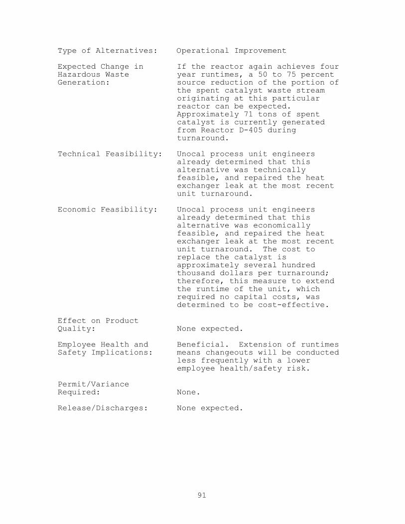
Type of Alternatives: Operational Improvement
Expected Change in If the reactor again achieves fourHazardous Waste year runtimes, a 50 to 75 percentGeneration: source reduction of the portion of
the spent catalyst waste streamoriginating at this particularreactor can be expected.Approximately 71 tons of spentcatalyst is currently generatedfrom Reactor D-405 duringturnaround.
Technical Feasibility: Unocal process unit engineersalready determined that thisalternative was technicallyfeasible, and repaired the heatexchanger leak at the most recentunit turnaround.
Economic Feasibility: Unocal process unit engineersalready determined that thisalternative was economicallyfeasible, and repaired the heatexchanger leak at the most recentunit turnaround. The cost toreplace the catalyst isapproximately several hundredthousand dollars per turnaround;therefore, this measure to extendthe runtime of the unit, whichrequired no capital costs, wasdetermined to be cost-effective.
Effect on ProductQuality: None expected.
Employee Health and Beneficial. Extension of runtimesSafety Implications: means changeouts will be conducted
less frequently with a loweremployee health/safety risk.
Permit/VarianceRequired: None.
Release/Discharges: None expected.
91


Printed withSoy Inks
Printed OnRecycled Paper