Assessment of a Novel Imaging Technique for Commercial
10
International Workshop SMART MATERIALS, STRUCTURES & NDT in AEROSPACE Conference NDT in Canada 2011 2 - 4 November 2011, Montreal, Quebec, Canada 2011 CANSMART CINDE IZFP ASSESSMENT OF A NOVEL IMAGING TECHNIQUE FOR COMMERCIAL STRUCTURAL HEALTH MONITORING AND NDT SYSTEMS Patrice Masson 1 , Nicolas Quaegebeur 1 , Gabriel Vézina 1 , Adrien Brunel 1 , Philippe Micheau 1 , Nezih Mrad 2 1 GAUS, Mechanical Engineering Department, Université de Sherbrooke, Sherbrooke, QC, J1K 2R1, Canada [email protected] 2 Department of National Defence (DND), Defence R&D Canada (DRDC), Ottawa, ON, K1A 0R6, Canada [email protected] ABSTRACT In this study, a novel imaging technique is assessed with two commercial systems used in damage detection: i) a structural health monitoring (SHM) system based on an array of piezoceramic sensors and actuators for in-plane inspection and ii) a non-destructive testing (NDT) system based on a phased-array device for through-the-thickness inspection. The imaging approaches used in these systems are based on either through-path propagation or time-of-flight (ToF), and the knowledge of the velocity of ultrasonic waves in the structure. While these techniques assume non-dispersive wave propagation, the proposed imaging technique exploits the dispersion of waves as it is based on the phase velocity. The signal measured at a given sensor is correlated with a theoretical prediction of a propagated burst in the structure and, combining the results for multiple sensors, an image of the reflectors in the structure is obtained. This paper presents the implementation of the novel imaging technique in the existing systems, including considerations for physical access to the signals and their conditioning. The performance of the existing imaging approaches is compared with the novel imaging technique proposed. The first assessment is conducted on simple test structures such as standard blocks. The full assessment of the novel imaging technique is then conducted on riveted plates with simulated cracks of two different lengths. Imaging results are presented for a number of damage detection scenarios on this structure. The benefit of the novel imaging technique is discussed. Keywords: Damage imaging, structural health monitoring, non-destructive testing, piezoceramics, riveted plates.
Transcript of Assessment of a Novel Imaging Technique for Commercial

International Workshop SMART MATERIALS, STRUCTURES & NDT in AEROSPACE
Conference NDT in Canada 2011
2 - 4 November 2011, Montreal, Quebec, Canada
2011 CANSMART CINDE IZFP
ASSESSMENT OF A NOVEL IMAGING TECHNIQUE FOR COMMERCIAL STRUCTURAL HEALTH MONITORING AND NDT
SYSTEMS
Patrice Masson1, Nicolas Quaegebeur1, Gabriel Vézina1, Adrien Brunel1, Philippe Micheau1, Nezih Mrad2
1GAUS, Mechanical Engineering Department, Université de Sherbrooke, Sherbrooke, QC, J1K 2R1, Canada [email protected]
2Department of National Defence (DND), Defence R&D Canada (DRDC), Ottawa, ON, K1A 0R6, Canada [email protected]
ABSTRACT In this study, a novel imaging technique is assessed with two commercial systems used in damage detection: i) a structural health monitoring (SHM) system based on an array of piezoceramic sensors and actuators for in-plane inspection and ii) a non-destructive testing (NDT) system based on a phased-array device for through-the-thickness inspection. The imaging approaches used in these systems are based on either through-path propagation or time-of-flight (ToF), and the knowledge of the velocity of ultrasonic waves in the structure. While these techniques assume non-dispersive wave propagation, the proposed imaging technique exploits the dispersion of waves as it is based on the phase velocity. The signal measured at a given sensor is correlated with a theoretical prediction of a propagated burst in the structure and, combining the results for multiple sensors, an image of the reflectors in the structure is obtained. This paper presents the implementation of the novel imaging technique in the existing systems, including considerations for physical access to the signals and their conditioning. The performance of the existing imaging approaches is compared with the novel imaging technique proposed. The first assessment is conducted on simple test structures such as standard blocks. The full assessment of the novel imaging technique is then conducted on riveted plates with simulated cracks of two different lengths. Imaging results are presented for a number of damage detection scenarios on this structure. The benefit of the novel imaging technique is discussed. Keywords: Damage imaging, structural health monitoring, non-destructive testing, piezoceramics, riveted plates.

2011 CANSMART CINDE IZFP
INTRODUCTION
Current Non Destructive Testing (NDT) of thin-wall structures (e.g. aircraft shells, tanks, pipes) involves meticulous through-the-thickness scan over large areas. A built-in Structural Health Monitoring (SHM) approach, rather than a traditional NDT type maintenance approach, would be most desirable for this application, since the associated costs would be reduced by substituting the current schedule-based maintenance approach by condition-based maintenance [1]. Among the various techniques available, a SHM system based on Lamb wave propagation with piezoelectric transducers seems to be a cost-effective method for a quick and continuous inspection of thin-wall metallic or composite structures.
Most of the damage detection and localization approaches are currently based on the measurement of a Time-of-Flight (ToF) and the knowledge of the group velocity for a mode propagating at a given frequency. Such approaches have been used within imaging techniques to process the signals measured by the elements of arrays [2]. As an example, the Embedded Ultrasonic Structural Radar (EUSR) [3] uses a phased-array approach with a round-robin procedure to locate defects, in its simplest implementation, in the far-field of the array. In that case, the localization of the reflectors obtained in the image relies on the maximum of the measured time-domain signal or its envelope. This can be challenging when wave propagation becomes dispersive. Even if specific low-dispersive modes are injected and/or measured in the structure using selective actuators and sensors [4], mode conversion at discontinuities might generate dispersive modes which superimpose with the targeted modes. This effect significantly complicates the measurement of the ToF associated with the echoes in the time-domain signals and therefore impairs the localization of the reflectors and leads to biased diagnostic. A number of approaches have been proposed to extract mode-related information from a time domain signal affected by a dispersive medium. The matching pursuit algorithm has been proposed using dispersion-inspired chirps have also been proposed in the matching pursuit approach [5] and efficiently implemented. Strategies for compensating the effects of dispersion have been proposed [6] to recover the shape of the input signal in the measured signal, and thus providing a better estimate of the ToF.
In the present paper, a technique called Excitelet [7] is exploited for the imaging of damages in structures using the correlation of the measured signals at elements of piezoceramic arrays with dispersed versions of the excitation signal. The first section presents the formulation of the novel imaging approach. Then, the approach is assessed with measured signals obtained from two distinct technologies: a NDT system and a commercially available SHM system. The implementation of the Excitelet algorithm is described, together with the experimental test benches used for the validation. A comparison of imaging results obtained using existing algorithms and Excitelet algorithm is presented.
THE EXCITELET IMAGING TECHNIQUE
The principle of correlation approaches for analysis of dispersed signals is based on the use of elementary time-function, called atom functions, that are subject to mathematical operations, such as time-frequency shifts, in order to create a dictionary of functions that are then correlated with the analyzed signal [5]. The feature extraction is then performed by minimizing the difference between synthesized and analyzed signals. In the present study, a similar approach is used for imaging of reflectors in a structure mounted with piezoceramic arrays. Fig. 1 presents

2011 CANSMART CINDE IZFP
the geometry considered in the formulation where A and S represent the actuator and sensor piezoceramics and O the observation (scanning) point. The imaging principle is to compute for each observation point O(xo,yo) a damage index that represents the possible presence of a damage at this point in the structure. This is performed by correlating the measured signal SAS(t) between actuator A and sensor S with the theoretical signal TAS(xo,yo,t) computed after propagation and scattering by a possible damage located at the observation point O. The correlation factor CAS(xo,yo) is defined by:
(1)
Fig. 1: Definition of coordinate system for actuator (A), sensor (S) and scanning point (O).
In previous studies using chirplet method for feature extraction of dispersed signals, the computed signals for dictionary functions are based on dispersion of atom functions such as Gabor functions or burst signals. The first imaging attempt using correlation coefficients, named EUSR is a variant of this approach [3] where the dispersion is not taken into account. In this case, the theoretical signal TAS(xo,yo,t) associated with observation point O is a Dirac delta function shifted at the time step associated with ToF of the generated Lamb wave:
(2)
where P(xo,yo) represents the compensation for cylindrical attenuation of signal with respect to the observation distance assuming that the damage acts as an omnidirectional reflector:
(3)
and δ stands for the Dirac delta function, ∆ tb denotes half of the duration of input signal and ∆ ta and ∆ ts represent the ToF associated with actuator and sensor distances respectively:
(4)
where cg represent the group velocity associated with mode and frequency of interest and da(xo,yo) and ds(xo,yo) denote the propagation distances as defined in Fig. 1:
(5)

2011 CANSMART CINDE IZFP
In the present study, a similar principle of imaging is used where the theoretical signal TAS(xo,yo,t) is now chosen in order to be more representative of the measured signal, as illustrated in Fig. 2. Thus, the mother atom function is chosen as the experimental input signal and the function dictionary is computed using theoretical propagation properties over a large bandwidth taking into account the dispersion of the medium. This approach allows extracting features even in frequency and modes ranges with high dispersion characteristics [7]. Considering weak coupling between circular piezoceramics and structure and assuming that the damage is acting as a perfectly omnidirectional reflector, the theoretical transfer function m
ASH (xo,yo,ω ) between
actuator A and sensor S, after possible reflection at the observation point O, and associated with mode m is defined in the frequency domain by [8]:
(6)
where ω denotes the angular frequency, km(ω ) the wavenumber associated with mode m, )2(1H is
the complex Hankel function of first order and second kind, da and ds represent the propagation distance defined in Eq. 5, and Fm(ω ) stands for the frequency dependence of the amplitude of the generated Lamb wave due to the piezoceramic coupling with host structure. The formulation for Fm(ω ) can be found for various piezoceramic geometries such as rectangular piezoceramics [8].
Fig. 2: Illustration of the correlation principle for EUSR and Excitelet approaches: (a) input signal U(t); (b) measured signal SAS(t); example of dictionary function TAS(xo,yo,t) for EUSR
algorithm (c) and Excitelet algorithm (d) at given scanning point (xo,yo).
Considering far-field radiation, Eq. 6 can be approximated for computational efficiency by [7]:
(7)
This transfer function is then used to compute the theoretical function TAS(xo,yo,t) in the time domain based on propagation of signal U(t) generated at the actuator. This calculation can

2011 CANSMART CINDE IZFP
be performed using inverse Fourier transform of transfer function convoluted with input signal, which is expressed, for the Excitelet case as:
(8)
where ∗ represents the convolution product. In practice, the convolution product is directly implemented as a product in the frequency domain in order to reduce computational costs. The calculation of correlation coefficients is performed using Eq. 1 for each sensor / actuator pair but is normalized by the norms of the theoretical and measured signals:
(9)
Using a round-robin approach, the correlation coefficients are summed in order to obtain the damage index (image) corresponding to mode m:
(10)
Multimodal imaging can also be used by multiplying damage indexes for different modes [7] and is considered in this work with modes A0 and S0:
(11)
ASSESSMENT OF EXCITELET WITH COMMERCIAL SYSTEMS
NDT system – Omniscan MX 16:64M from Olympus NDT
The novel imaging algorithm is first assessed using the Omniscan MX 16:64M from Olympus NDT [9], a commercially available system largely used for through-the-thickness ultrasonic NDT inspection using bulk waves. As presented in Fig. 3, the system provides a user-interface for the selection of parameters and plotting of the scans in either the time, cartesian or polar domains. A number of ultrasound transducers can be connected to the system and the one used in this work is the phased-array 5L64-A12 transducer (tuned to 4,5 MHz), together with the wedge SA12-N55S with apex angle of 45°. As a first step in the testing of the Excitelet imaging algorithm with this system, the signals from the acquisition unit are obtained using the DataAcess software, as illustrated in Fig. 4a). In future work, the signals will be extracted before the phased-array unit, i.e. at the sensors outputs.
The experimental test bench consists of an aluminium beam (with section of 2,54 cm x 1,27 cm) where 5 holes have been drilled, as shown in Fig. 4b). The first 16 elements of the of the phased-array transducer were set active to plot sectorial scans (S-scans) between 10° and 70°. To implement the Excitelet algorithm, the inspected area is meshed with a 1 mm precision and the algorithm processes the data from DataAcess in MATLAB.
2011 CANSMART CINDE IZFP
a) b) c)
Fig. 3: The Omniscan MX system (a) with wedge used in NDT inspection (b) and scans (c).
a) b) Fig. 4: Data processing for Omniscan MX and Excitelet (a) and the experimental test bench (b).
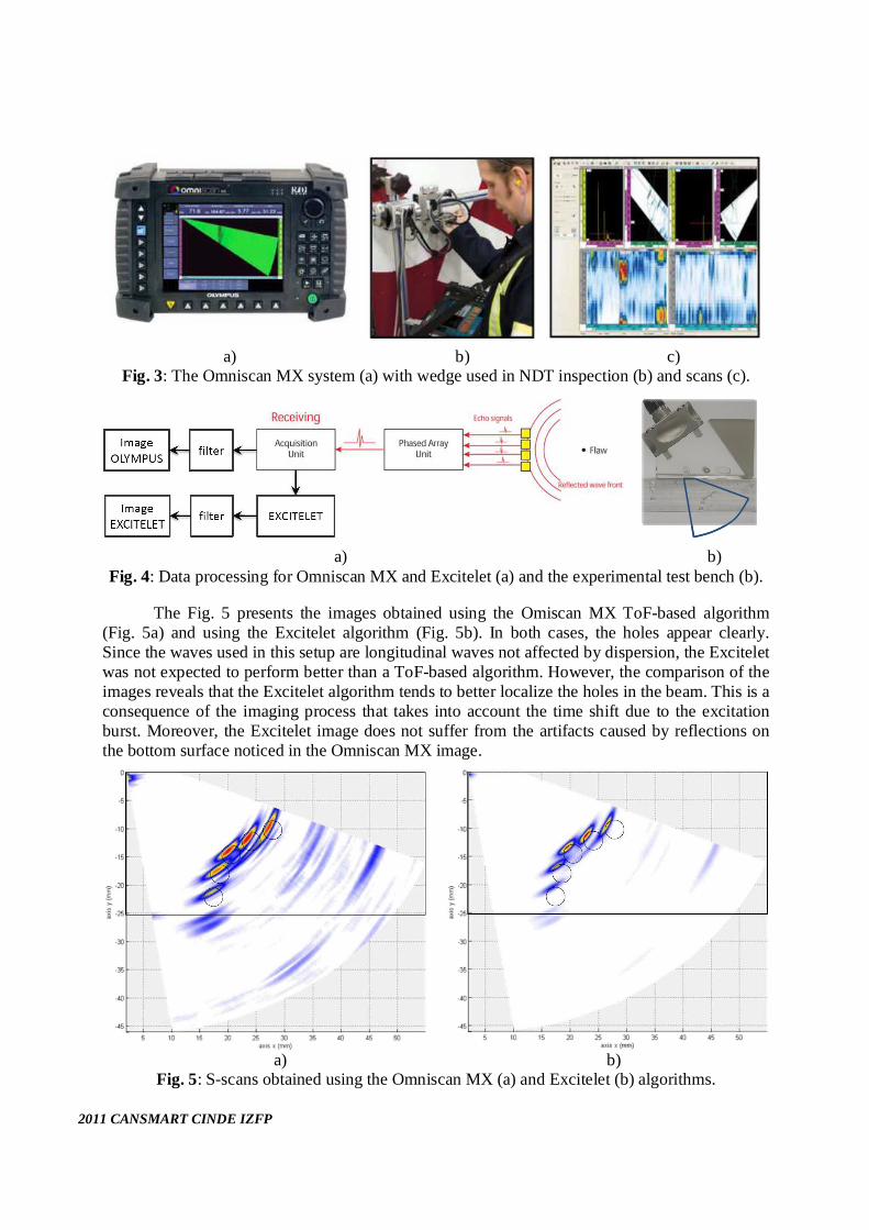
The Fig. 5 presents the images obtained using the Omiscan MX ToF-based algorithm (Fig. 5a) and using the Excitelet algorithm (Fig. 5b). In both cases, the holes appear clearly. Since the waves used in this setup are longitudinal waves not affected by dispersion, the Excitelet was not expected to perform better than a ToF-based algorithm. However, the comparison of the images reveals that the Excitelet algorithm tends to better localize the holes in the beam. This is a consequence of the imaging process that takes into account the time shift due to the excitation burst. Moreover, the Excitelet image does not suffer from the artifacts caused by reflections on the bottom surface noticed in the Omniscan MX image.
a) b)
Fig. 5: S-scans obtained using the Omniscan MX (a) and Excitelet (b) algorithms.

2011 CANSMART CINDE IZFP
SHM system – SMART Layer, ScanGenie and SmartComposite from Acellent Technologies
The novel imaging algorithm was also assessed using a system commercialized by Acellent Technologies [10] for SHM. As illustrated in Fig. 6, the system is composed of embedded PZT sensors called SMART Layer, the ScanGenie acquisition module and the SmartComposite software for parameters setting, signal processing and image plotting. For the purpose of validation of the novel imaging algorithm, piezoelectric circular patches bonded to the structure are used in this study.
a) b) c) Fig. 6: The SMART Layer (a and b) and SmartComposite (c) system used in SHM.
The SmartComposite interface allows for the definition of the sensors layout, the selection of the actuation signal, the management and the visualization of the raw measured signals in the time domain, and the processing of the signals for imaging of the structure. The system requires the measurement of a baseline and four approaches are available for damage extraction: i) difference of mean signal amplitude, ii) mean signal amplitude of scatter signal, iii) differences of total signal energy and iv) total signal energy of scatter signal. The system also allows for sensor diagnostics and temperature calibration. The image is obtained using a direct path approach (Fig. 7a), where a damage can be detected by observing its impact on the time signal of a wave propagating through it. By contrast, the Excitelet algorithm is based on reflection at the damage, as illustrated in Fig. 7b), allowing a reduction of required sensors for a given area to inspect.
a) b)
Fig. 7: Direct path imaging with SmartComposite (a) and reflection imaging with Excitelet (b).
The system was applied to a typical aerospace structure composed of a riveted 6061-T6 aluminum lap-joint with sealant, as shown in Fig. 8a). The structure is instrumented with 8 PZT of diameter 10 mm, allowing an inspection zone of 15 cm x 10 cm encompassing the rivet line, as shown in Fig. 8b). Imaging results are presented in the following for simulated cracks between two rivets, with lengths of 3 mm and 6 mm (Fig. 9). The analysis is conducted using a 5,5 cycles Hanning windowed burst at 200 kHz.

2011 CANSMART CINDE IZFP
a) b) Fig. 8: Instrumented structure (a) together with defined paths (b).
a) b)
Fig. 9: Simulated crack in the rivet line with lengths of 3 mm (a) and 6 mm (b)
The comparison between SmartComposite and Excitelet is presented in Figs. 10 and 11. In this case, since (dispersive) guided waves are used, some improvement was expected on the detection and localization using the Excitelet algorithm. In fact, modes A0, S0 and multimodal imaging with both modes were used with the Excitelet algorithm. From the results obtained, it generally appears that both SmartComposite and Excitelet allow detection of damage and that the damage index increases with the crack size. However, the 3 mm crack is hardly shown by the SmartComposite algorithm, with a threshold of 0. The mean signal amplitude was also used (results not shown here) but did not lead to detection of the 3 mm crack. The localization of the cracks seems slightly better with the Excitelet algorithm, and more robust when using S0 mode or multimodal imaging. Moreover, progression of the reflected energy obtained with Excitelet imaging can be used to estimate damage size.
CONCLUSIONS
This paper presents the implementation of the Excitelet algorithm with measured signals obtained from commercially available systems used in damage imaging. The approach is assessed with measured signals obtained from two distinct technologies: a NDT system based on a phased-array device for through-the-thickness inspection and a commercially available SHM system based on an array of piezoceramics for in-plane inspection. Two test benches, one for each technology, were presented and the implementation of the Excitelet algorithm was discussed.

2011 CANSMART CINDE IZFP
Fig. 10: Crack imaging results obtained with SmartComposite using difference of total signal energy and total signal energy of scatter signal.
Fig. 11: Crack imaging results obtained with Excitelet algorithm using single modes A0 and S0
and multimodal imaging with both modes.

2011 CANSMART CINDE IZFP
For the NDT system, the Excitelet algorithm has demonstrated an improvement in the localization and resolution of the images obtained for the test bench defined in this work. This is in spite of the limitations in the access to raw signals.
For the SHM system, the Excitelet has shown a better ability to detect a 3 mm crack in a rivet line, with better resolution for larger cracks. Since the Excitelet algorithm provides a single damage index (image), i.e. does not require choosing between one of four indicators as with SmartComposite software, the Excitelet algorithm has shown increased robustness.
Ongoing work aims at implementing this approach with the NDT system using raw signals provided by the phased-array transducer, before any processing by the unit. Extension to imaging using all the 64 elements as active and within a round-robin process will allow obtaining more precise damage location and local information on the curvature and extent of the damages. The Excitelet algorithm will be used with the signal obtained from the commercial SHM system (SMART Layer) bonded on real aerospace structures.
ACKNOWLEDGEMENTS
This work has been supported by the Idea to Innovation (I2I) program from the Natural Sciences and Engineering Research Council of Canada (NSERC). The authors would also like to acknowledge the help from Pierre-Claude Ostiguy, and the contribution from Acellent Technologies and Olympus NDT to this project.
REFERENCES
1. Farrar, C. and Worden, K., “An introduction to structural health monitoring”, Philosophical Transactions of the Royal Society, 365, 303–315, 2007.
2. Masson, P. and Micheau, P., “Compact piezoelectric arrays for imaging strategies in damage detection,” in International Workshop on Structural Health Monitoring (IWSHM), 2009.
3. Yu, L. and Giurgiutiu, V., “In situ 2-d piezoelectric wafer active sensors arrays for guided wave damage detection,” Ultrasonics 48, 117–135, 2008.
4. Monkhouse, R., Wilcox, P., Lowe, M., Dalton, R., and Cawley, P., “The rapid monitoring of structures using interdigital Lamb wave transducers,” Smart Materials and Structures 9, 304–309, 2000.
5. Raghavan, A. and Cesnik, C., “Guided-wave signal processing using chirplet matching pursuits and mode correlation for structural health monitoring,” Smart Materials and Structures 16, 355–366, 2007.
6. Wilcox, P., “A rapid signal processing technique to remove the effect of dispersion from guided wave signals,” IEEE Transactions on Ultrasonic, Ferroelectric and Frequency Control 50(4), 419–427, 2003.
7. Quaegebeur, N., Masson, P., Langlois-Demers, D., and Micheau, P., “Dispersion-based imaging for structural health monitoring using sparse and compact arrays,” Smart Materials and Structures 20, 025005, 2011.
8. Raghavan, A. and Cesnik, C., “Finite-dimensional piezoelectric transducer modeling for guided wave based structural health monitoring,” Smart Materials and Structures 14, 1448–1461, 2005.
9. Olympus NDT (www.olympusndt.com) 10. Acellent Technologies, Inc. (www.acellent.com)