Assessment and Evaluation of Timber Piles Used in Nebraska ...
61
University of Nebraska - Lincoln DigitalCommons@University of Nebraska - Lincoln Nebraska Department of Transportation Research Reports Nebraska LTAP 4-2014 Assessment and Evaluation of Timber Piles Used in Nebraska for Retrofit and Rating Atorod Azizinamini University of Nebraska - Lincoln, [email protected] Alireza Mohammadi Jawad H. Gull Ramin Taghinezhad Follow this and additional works at: hp://digitalcommons.unl.edu/ndor Part of the Transportation Engineering Commons is Article is brought to you for free and open access by the Nebraska LTAP at DigitalCommons@University of Nebraska - Lincoln. It has been accepted for inclusion in Nebraska Department of Transportation Research Reports by an authorized administrator of DigitalCommons@University of Nebraska - Lincoln. Azizinamini, Atorod; Mohammadi, Alireza; Gull, Jawad H.; and Taghinezhad, Ramin, "Assessment and Evaluation of Timber Piles Used in Nebraska for Retrofit and Rating" (2014). Nebraska Department of Transportation Research Reports. 158. hp://digitalcommons.unl.edu/ndor/158
Transcript of Assessment and Evaluation of Timber Piles Used in Nebraska ...

University of Nebraska - LincolnDigitalCommons@University of Nebraska - LincolnNebraska Department of Transportation ResearchReports Nebraska LTAP
4-2014
Assessment and Evaluation of Timber Piles Used inNebraska for Retrofit and RatingAtorod AzizinaminiUniversity of Nebraska - Lincoln, [email protected]
Alireza Mohammadi
Jawad H. Gull
Ramin Taghinezhad
Follow this and additional works at: http://digitalcommons.unl.edu/ndor
Part of the Transportation Engineering Commons
This Article is brought to you for free and open access by the Nebraska LTAP at DigitalCommons@University of Nebraska - Lincoln. It has beenaccepted for inclusion in Nebraska Department of Transportation Research Reports by an authorized administrator of DigitalCommons@University ofNebraska - Lincoln.
Azizinamini, Atorod; Mohammadi, Alireza; Gull, Jawad H.; and Taghinezhad, Ramin, "Assessment and Evaluation of Timber PilesUsed in Nebraska for Retrofit and Rating" (2014). Nebraska Department of Transportation Research Reports. 158.http://digitalcommons.unl.edu/ndor/158
NDOR Research Project Number -------
Assessment and Evaluation of Timber Piles Used in Nebraska for Retrofit and Rating
Alireza Mohammadi Jawad H. Gull, Ph.D. Ramin Taghinezhad
Atorod Azizinamini, Ph.D., P.E.
Department of Civil and Environmental Engineering Florida International University
Miami, Florida
10555 W. Flagler Street, EC 3600 Miami, FL 33174
Sponsored By
Nebraska Department of Roads
April, 2014
F I N A L
R E P O R T

ii
1. Report No.
2. Government Accession No.
3. Recipient's Catalog No.
4. Title and Subtitle
Assessment and Evaluation of Timber Piles Used in Nebraska for Retrofit and Rating
5. Report Date
April. 2014
6. Performing Organization Code
7. Author(s)
Alireza Mohammadi Jawad H. Gull Ramin Taghinezhad Atorod Azizinamini (PI)
8. Performing Organization Report No.
9. Performing Organization Name and Address
Civil and Environmental Engineering Florida International University 10555 W. Flagler Street, EC 3680 Miami, FL 33174 USA
10. Work Unit No. (TRAIS)
11. Contract or Grant No.
12. Sponsoring Agency Name and Address
State of Nebraska Department of Roads - Main Office P.O. Box 94759, Lincoln, Nebraska 68509-4759 1500 Highway 2, Lincoln, Nebraska 68502 USA
13. Type of Report and Period Covered
Final Report Jun. 2012-Apr. 2014
14. Sponsoring Agency Code
15. Supplementary Notes
16. Abstract
The cost of an effective retrofitting and rehabilitation of timber piles is less than cost of replacing the
piles. However, some of the retrofit options used in Nebraska failed to result in the expected
performance levels. Further, design and detailing of different retrofit schemes are not well defined.
Therefore, the objective of this project was to develop a set of guidelines to retrofit damaged timber
piles.
Different types of damages, methods of assessment, and repair procedures of the timber piles were
reviewed. Few repair methods were selected for detail investigation. Five full scale timber pile
specimens with different level of damages were prepared. The damage in each specimen was repaired
by using FRP wrap to capsulate the damaged region and filling it with either resin or grout or resin and
gravel. Guidelines are provided carry out the repair of timber piles in field using the selected repair
methods. Ultimate load tests were carried out on the specimens to evaluate the effectiveness of the repair
methods.
Test results show that grout is more effective in repairing large cavity-type damages compared to resin.
Resin might be more effective for repairing cracks and small cavities in timber piles. Further, the failure
load of the repaired pile specimens was at least five times greater than the design load capacity of the
timber pile.
17. Key Word
Bridge, Timber piles, Damages, Assessment, Repair, Retrofit, Testing, Nebraska.
18. Distribution Statement
No restrictions.
19. Security Classif. (of this report)
Unclassified 20. Security Classif. (of this page)
Unclassified 21. No. of Pages
60 22. Price

iii
Disclaimer
The opinions, findings, and conclusions expressed in this publication are those of the authors and not
necessarily those of the Nebraska Department of Roads.

iv
Executive Summary
Timber piles are used in the substructure of many bridges throughout Nebraska with the majority being
found on county bridges. These timber piles can deteriorate from different damages over an extended
period of time. One obvious option to address the conditions created by damaged timber piles is to
replace the piles; however, the cost of an effective rehabilitation of timber piles can be much less than
the cost of replacing the piles. Different repair and rehabilitation options are available for the timber
piles and some of the retrofit options used in Nebraska failed to result in the expected performance
levels. Further, design and detailing of other retrofit schemes are not well defined.
Therefore, the main objective of this project was to develop a set of guidelines to retrofit damaged
timber piles. This objective was achieved by reviewing the available retrofit options through a state
DOT survey, selecting a few repair options for detailed investigation, and conducting experimental work
to evaluate the effectiveness of the repair methods.
Different types of damages, methods of assessment, and repair procedures of the timber piles are
reviewed. Select repair methods were investigated in this study. These repair methods use FRP wrap to
capsulate the damaged region of the pile, which is then filled with resin, grout, or resin and aggregate.
Ultimate load tests were carried out on five full scale timber pile specimens with different levels of
damage and repaired using different methods to evaluate the effectiveness of the repair methods.
Test results show that grout is more effective in repairing large cavity-type damages compared to resin.
However, resin may be more effective for repairing cracks and small cavities. Further, test results
indicate that the failure load of a repaired pile specimen was at least five times greater than the design
load capacity of the pile.

v
Table of Contents
Disclaimer ................................................................................................................................................. iii
Executive Summary ................................................................................................................................. iv
List of Figures .......................................................................................................................................... vii
List of Tables ............................................................................................................................................ ix
Chapter 1 Introduction ........................................................................................................................... 1 1.1 Objectives ....................................................................................................................................... 2
1.2 Organization of the report ............................................................................................................... 3
Chapter 2 Damages and condition assessment ..................................................................................... 4 2.1 Types of damages ........................................................................................................................... 4
2.1.1 Biological damage .................................................................................................................. 4
2.1.2 Physical damage...................................................................................................................... 5
2.2 Methods of assessment ................................................................................................................... 5
2.2.1 Visual inspection ..................................................................................................................... 6
2.2.2 Probing and pick test ............................................................................................................... 6
2.2.3 Moisture measurement ............................................................................................................ 7
2.2.4 Sounding ................................................................................................................................. 7
2.2.5 Mechanical wave tests ............................................................................................................ 8
2.2.6 Drill resistance tests ................................................................................................................ 8
2.2.7 Preservative retention analysis ................................................................................................ 8
Chapter 3 Repair and protection ........................................................................................................... 9 3.1 Methods for Protection of Timber Piles.......................................................................................... 9
3.2 Method for Restoring Timber Piles ................................................................................................ 9
3.2.1 Splicing ................................................................................................................................... 9
3.2.2 Cutting and Posting ............................................................................................................... 10
3.2.3 Grout Injection ...................................................................................................................... 11
3.2.4 Concrete Jackets.................................................................................................................... 12
3.2.5 FRP Wraps ............................................................................................................................ 12
Chapter 4 Repair methods investigated .............................................................................................. 17 4.1 Repair procedure ........................................................................................................................... 17
4.1.1 Jacketing ............................................................................................................................... 17
4.1.2 Injection ................................................................................................................................ 22
Chapter 5 Testing .................................................................................................................................. 25 5.1 Test Specimens ............................................................................................................................. 25
5.2 Test set up ..................................................................................................................................... 28
5.3 Instrumentation ............................................................................................................................. 30
5.4 Testing procedure.......................................................................................................................... 31
5.5 Test results .................................................................................................................................... 32
Chapter 6 Summary and conclusions .................................................................................................. 38
References ................................................................................................................................................ 40
Appendix A: Survey of DOT practices ................................................................................................ 42 A.1 Oregon....................................................................................................................................... 42
A.2 Nebraska ................................................................................................................................... 42
A.3 Arkansas .................................................................................................................................... 42
A.4 Mississippi ................................................................................................................................ 42
A.5 Iowa........................................................................................................................................... 42
A.6 Illinois ....................................................................................................................................... 43

vi
A.7 Maine ........................................................................................................................................ 43
A.8 Missouri .................................................................................................................................... 43
A.9 New Jersey ................................................................................................................................ 43
A.10 North Dakota ............................................................................................................................. 43
A.11 Virginia ..................................................................................................................................... 43
A.12 West Virginia ............................................................................................................................ 43
Appendix B: Detailed Description of Materials Used in Repair ....................................................... 44 B.1 GFRP......................................................................................................................................... 44
B.2 Epoxy ........................................................................................................................................ 45
B.3 Resin ......................................................................................................................................... 46
B.4 SARKRETE
non-shrink construction grout ........................................................................... 47
Appendix C: Test sequence for one specimen ..................................................................................... 48

vii
List of Figures
Figure 1.1: Examples of observed damages in Timber Piles in Nebraska.................................................. 1
Figure 2.1 Breaks in preservative barriers by exterior damage leads to premature decay [2] .................... 5
Figure 2.2 Electronic moister meters for timber ......................................................................................... 7
Figure 3.1 Timber pile repair scheme by splicing using reinforced concrete after US Army FM 5-134
(1985) ........................................................................................................................................................ 10
Figure 3.2 Cutting and posting of damaged timber piles [7] .................................................................... 11
Figure 3.3 Reinforced concrete jacketed timber pile [7] .......................................................................... 12
Figure 3.4 Repair technique using GFRP wet-wrap sheets [9] ................................................................. 13
Figure 3.5 Repair method using FRP composite shells [11] .................................................................... 14
Figure 3.6 FRP composite repair system with (a)cement-based grout (b)shear connectors and
polyurethane grout [11]............................................................................................................................. 15
Figure 3.7 Sequence of the proposed retrofit procedure .......................................................................... 16
Figure 4.1: Guidelines for GFRP sheet sizing for jacketing ..................................................................... 18
Figure 4.2: Surface roughening and application of epoxy to GFRP sheet................................................ 19
Figure 4.3: Preparing pile for GFRP sheet................................................................................................ 20
Figure 4.4: Wrapping GFRP sheet around the pile ................................................................................... 21
Figure 4.5: Holding GFRP sheet around the pile by SaranTM
plastic wrap .............................................. 21
Figure 4.6: Wire mesh for holding aggregate in damage region .............................................................. 22
Figure 4.7: Injection of pre-mixed resin using a pressure pot .................................................................. 23
Figure 5.1: Full Scale timber pile test specimens ..................................................................................... 25
Figure 5.2: Description of test specimens ................................................................................................. 26
Figure 5.3: Different levels of damage in timber pile test specimens ...................................................... 27
Figure 5.4: Expected failure at the small fixed end of the pile ................................................................. 29
Figure 5.5: Test setup for testing full scale timber pile specimens ........................................................... 30
Figure 5.6: Instrumentation plan ............................................................................................................... 31
Figure 5.7: Failure of specimen 1 (1 inch deep damage filled with resin) ............................................... 33
Figure 5.8: Failure of specimen 2 (1.5 inch deep damage filled with resin) ............................................ 33
Figure 5.9: Failure of specimen 3 (2 inch deep damage filled with grout) ............................................... 34
Figure 5.10: Failure of specimen 4 (2 inch deep damage filled with grout) ............................................. 34
Figure 5.11: Failure of specimen 5 (2 inch deep damage filled with resin + gravel) ............................... 35
Figure 5.12: Load deflection curve and failure mode of specimens ......................................................... 36

viii
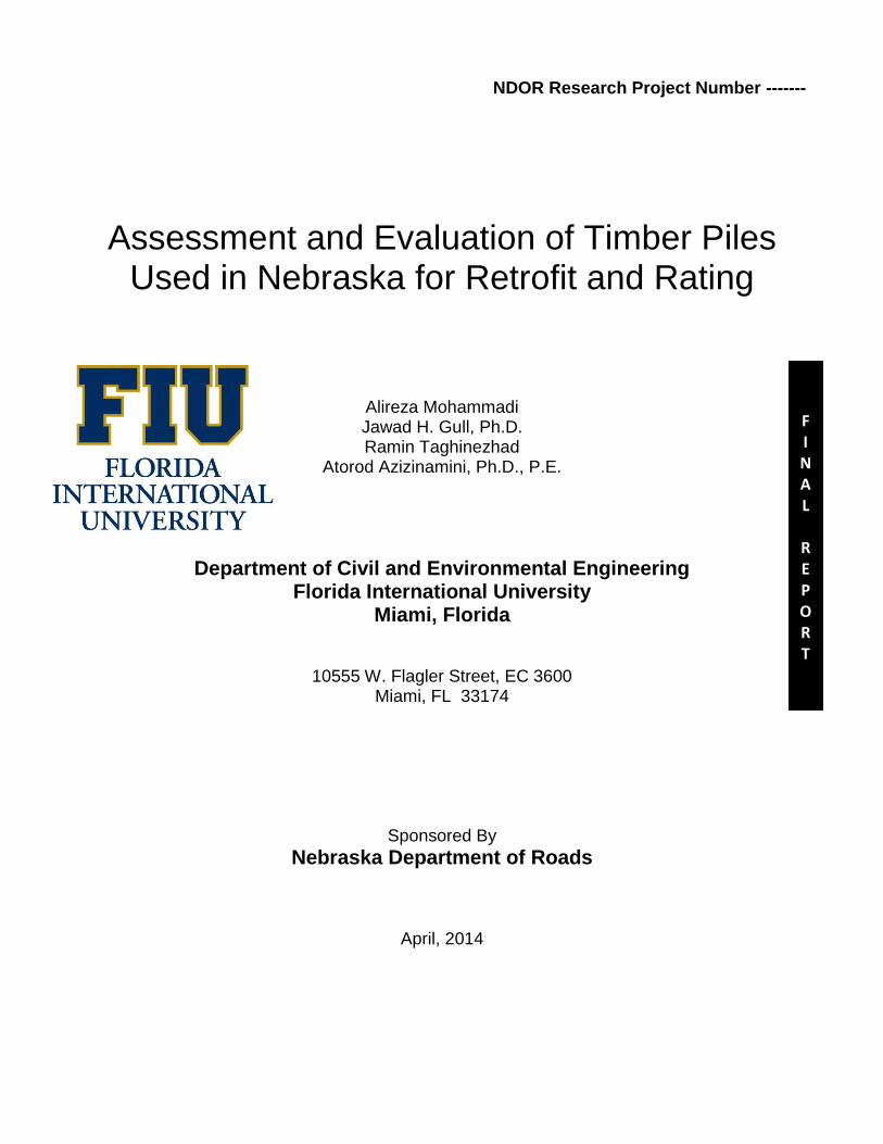
Figure C.1 Strain versus time at different stages of loading ..................................................................... 49
Figure C.2 Axial force versus time at different stages of loading ............................................................ 49
Figure C.3 Moment versus time at different stages of loading ................................................................. 50
Figure C.4 Forces applied by each jack through the whole steps of loading protocol ............................. 50
Figure C.5 Measured deflection at different locations along the timber pile length ................................ 51

ix
List of Tables
Table 2.1: Summary of advantages and disadvantages of visual inspection .............................................. 6
Table 2.2: Summary of advantages and disadvantages of probing and pick test ....................................... 6
Table 5.1: Details of timber pile test specimens ....................................................................................... 28
Table 5.2: Lateral displacement and moment applied to each specimen .................................................. 32
Table 5.3: Maximum axial load and Design capacity of timber pile specimens ...................................... 37

1
Chapter 1 Introduction
Many timber piles used in the substructure of bridges throughout Nebraska have different types and
extent of damage. The damaged area is typically located immediately beneath ground level or in the
splash zone, which is defined as a boundary between the top surface of the water and the air. Below the
water level there is water, but not enough oxygen. Above water level, there is oxygen, but not enough
water. In the splash zone, partly due to changes in water levels, the sub-structure elements are subject to
both water and oxygen, the two elements needed to cause deterioration. Figure 1.1 show some typical
damages observed in Timber piles in Nebraska.
Figure 1.1: Examples of observed damages in Timber Piles in Nebraska
When only one timber pile is damaged, use of any retrofit technique may prove to be sufficient.
However, problems arise when several timber piles in a given pier experience damage. In these
situations a reliable engineering approach needs to be exercised. Further, field observations indicate that
when one pile shows signs of damage it will only be a short time before the same level of damages are
observed on other timber piles of the same pier.
In the past, the routine option to address the conditions create by damaged timber pile was complete
replacement of the pile. The cost of an effective rehabilitation of a timber pile is less than cost of
replacing the pile. Some of the past retrofit options used in Nebraska have failed to result in the expected
performance levels. Further, design and detailing of other retrofit schemes are not well defined, mainly
because of lack of test or research data. The retrofits options currently use in Nebraska are mainly
developed based on engineering judgments. In some cases these alternatives have not achieved their
expected performance levels.

2
There is no a comprehensive research on timber pile with eccentric compression load available. A study
by [1] shows current rating method is not conservative while it only take account concentric
compressive load, and the results could lead to an overestimate capacity while the pile strength was
significantly reduced under eccentric load compared to concentric load. The current code provisions take
into account only concentric compressive force on timber pile. This assumption that timber piles
carrying out pure eccentric compressive load is not valid for simply supported super structure spans
because if one span collapse the reaction of two other spans will lead to eccentric compressive load,
increase the moment and decrease the capacity of timber pile. According to the current code, it was
assumed that due to rigidity of concrete deck, timber pile is only under compressive load and no
eccentricity is considered for compressive applied load. The Army and Navy considered the interaction
of compression force and bending moment on wood elements in 1924. After that an interaction based on
axial and bending stress equation was developed, that lead to accurate results for short, intermediate and
long beam columns. Zahn tested Western Hemlock specimens 2in by 6in nominal size for a combination
of different axial and bending load. In order to calibrate the results for a longer specimens, over 400
extra specimen 18in length tested. Most experimental available results are related to small sawn lumber
and there is limited test results for timber pile with circular section. Totally, this report focused on test
retrofitting of 6 timber piles along different materials for repair at the ultimate load level.
This report focused on repairing of bridge timber piles at the damaged section, and different materials
take into account the effect of interaction of axial force and bending moment, resulting from the
eccentricity of applied axial load. In this research a simple and reliable retrofit technique was developed
by using resin, grout and combined resin and gravel to increase compression axial capacity of current
timber piles in old bridges. In this research an experimental work conducted to explore the effect of
retrofitting and loading eccentricity on the capacity of timber piles. Timber piles are not required to be
designed for combined compression and flexure loading by current AASHTO design provisions
although eccentricities are typically assigned to unsymmetrical loading of simply supported spans. Six
pile specimens were considered for experimental testing. These specimens were tested under combined
of compression and a small axial load eccentricity.
1.1 Objectives
The main objective of this project is to develop a set of guidelines to retrofit damaged timber piles.
Specific objectives of the project are as follows:

3
Conduct survey to establish the current state of practice as related to retrofitting damaged
timber piles in bridges.
Review the available retrofit options and, in consultation with NDOR bridge engineers, select a
few techniques worthy of considerations.
Construct full scale test specimens and repair them with selected repair methods and describe
different steps involved in the repair procedure.
Conduct the ultimate load tests on the timber pile specimen and evaluate the effectiveness of
the selected repair procedures.
Summarize the results and comment about the effectiveness of the repair method.
1.2 Organization of the report
This report is divided in five main chapters.
Chapter 2 describes different types of damages and methods to carry out inspection of the timber piles.
The types of damages are divided into two main categories that are biological damages and physical
damages. The type and extent of damages in timber piles can be evaluated by using different methods of
assessment. A brief description of each method of assessment is provided in this chapter.
Chapter 3 states different repair and protection procedures that are generally used for the timber piles.
The protection of timber pile is normally carried out by treating the wood with preservative. There is a
wide variety of repair methods that have been used or investigated in literature. This chapter provides a
brief summary of some of the repair methods.
Chapter 4 presents the details of the repair methods investigated as a part of this research project. Three
repair methods were investigated. The repair procedure described in section 4.1 provides the general
guidelines for implementing these repair procedures in the field. Jacketing and injection are the two
main steps that are required for repairing the pile using the repair methods described in this chapter.
Chapter 5 describes the load tests carried out on full scale timber pile specimens with different levels of
damages repaired by different repairing methods. Five full scale timber pile test specimen were tested
evaluate the effectiveness of repair method. The specimens were subjected to both axial and lateral
loads. Test results indicate that repaired pile specimens were able to carry at least five times of the
design load capacity used in structural design of timber pile bridges.

4
Chapter 2 Damages and condition assessment
It is difficult to estimate the remaining capacity of a damaged timber pile and the safety of the bridge
containing a deteriorated timber pile foundation. However, it is important to detect the type and extent of
damages in the piles so that appropriate repair can be carried out. A timely repair is essential in
extending the life of the bridge using timber pile foundations. Repair methods often depend on the type
and extent of damages. Different condition assessment techniques that can be used to assess the type and
extent of damages in timber are described in this chapter.
2.1 Types of damages
Damages in timber piles used as foundations of bridges can be categorized into biological damages and
physical damages. Biological damages are generally caused by different organism and result in decay of
the wood in piles. Physical damages are caused by different factors resulting in deterioration of the piles.
Following section discuss the biological and physical damage in more detail.
2.1.1 Biological damage
Biological damage is caused by different organisms causing the wood to decay. Rate of biological
damage depend on the environmental conditions and type of the organism. Following are the most
common organism causing biological damage in timber piles:
Fungi
Termites
Powderpost beetle
Carpenter ants
Bacteria and mold
Fungi are reported as the most destructive organism for timber pile used in bridges [2]. Rate of damage
caused by fungi depends on the environmental conditions. Most of the fungi grow rapidly in warm and
moist conditions. Termites are well known for causing damage to wood. The damage cause by termite is
much more rapid compared to damage caused by fungi. Powderpost beetles, carpenter ants, bacteria and
mold can also cause significant damage to wood depending on the prevailing conditions. Generally, cold
and dry conditions restrain the biological damage.

5
2.1.2 Physical damage
Physical damages are caused by different factors and cause the deterioration of exterior treated wood
cover. Damage of exterior protective cover provides biological mechanism access to interior untreated
wood resulting in decay of the interior wood. Different types of physical damages are shown in Figure
2.1. The most common type of physical damage is caused by impact of objects floating in water.
Physical damage is also caused by overloading due to heavy loads, failure of adjacent piles, and over-
tightening of the fasteners. Fire can destroy and cause failure of timber pile bridges in a matter of hours.
Partially burned timber pile can carry load depending on the remaining unburned cross section of the
pile.
(a) Mechanical Damage (b) Debris Damage (c) Fire Damage (d) Weathering/UV
Damage
Figure 2.1 Breaks in preservative barriers by exterior damage leads to premature decay [2]
2.2 Methods of assessment
Different methods of inspecting the timber piles are discussed in detailed in a report by Iowa State [3]. A
brief summary of each method followed by advantages and disadvantages is discussed in the following
sections.

6
2.2.1 Visual inspection
Visual inspection involves going to the site and inspecting the piles visually. Color changes, presence of
bleach, staining, corroded fasteners, splits, cracks, checks, crumbling and collapsed wood can be noticed
visually. Different advantages and disadvantages are listed in the Table 2.1.
Table 2.1: Summary of advantages and disadvantages of visual inspection
Advantages Disadvantages
Quick inexpensive method that is readily
applicable
Checks, decay at fasteners, end grain
decay, splitting, staining, surface decay,
ultraviolet degradation can be inspected [2]
Qualitative assessment of the piles can be
done
Small pockets of decay are difficult to
catch
No information regarding depth of decay
can be obtained
2.2.2 Probing and pick test
Probing can be done by moving a sharp pointed tool such as awl on the wood surface of the timber piles.
Generally the wood in good health is dense and difficult to penetrate with the pointed tool compared to
decayed wood.
In pick test a pointed tool is inserted in the pile and then moved sideward to pick a small piece of wood
out the pile. The sound and pattern of separation of the small piece picked from the wood pile gives an
indication of the condition of the wood pile. Wood in good condition breaks off to one side of the pick
away from the tool with a sharp sound. Decayed wood generally breaks above the pick’s point with a
dull sound.
Table 2.2: Summary of advantages and disadvantages of probing and pick test
Advantages Disadvantages
Quick inexpensive method that is readily
applicable
Probing test can locate pockets of decay
near surface of wood [2]
Pick test subjectively differential between
the sound and decayed wood [2]
Require some experience to reliably
interpret the results [2]

7
2.2.3 Moisture measurement
Excessive moisture in timber pile indicates the possibility decay. Moisture in timber pile can be measure
using a moisture meter that measures the electrical resistance between two points of the timber pile. This
electrical resistance is converted to equivalent moisture content using calibration charts built into the
moisture meter. A moister greater than 20 percent indicates that decay is most likely to start and a
thorough inspection of the pile is required.
Figure 2.2 Electronic moister meters for timber
2.2.4 Sounding
In this technique a hammer is hit on the surface of timber pile to assess the quality of wood in the pile.
Hitting hammer on different quality woods results in different sounds. An experienced person can
differentiate between sounds from hollow wood and healthy wood. Since this technique largely depends
on the judgment of inspector, it is generally used with other assessment techniques.

8
2.2.5 Mechanical wave tests
In this technique, defects in the timber pile are detected based on the speed of the mechanical wave
traveling through the pile. Speed of mechanical or stress wave in defected wood is slower compared to
speed of the waves in healthy wood. Signal reliability, access to complete surface, magnitude of
damage, and lack of differentiation between different defects are some of the challenges with this
inspection method. More details about this method can be found in literature [4] [5] [6].
2.2.6 Drill resistance tests
Healthy wood has more density and provide more resistance to drilling compared to decayed or
defective wood. Drill resistance devices can measure the resistance of the wood to drilling indicated the
quality of the wood. This method can be used with other inspection techniques.
2.2.7 Preservative retention analysis
Preservative retention analysis is used for assessing the capability of the wood to retain different
preservatives used for protecting the wood. Following are the different types of preservatives used for
protecting the wood:
Creosote
Pentachlorophenol
Copper Naphthenate
Chromated Copper Arsenate (CCA)
Acid Copper Chromate (ACC)
Ammoniacal Copper Zinc Arsenate (ACZA)
The procedure to carry out preservative retention analysis for each preservative is different and is
specified by American Wood Protection Association (AWPA) standards.
Creosote retention analysis can be carried out according to AWPA A6-09 that specifies the method for
the determination of oil-type preservatives and water in wood.
Copper Naphthenate and Pentachlorophenol analysis can be carried out according to AWPA A5-05 that
specifies the standard methods for analysis of oil-borne preservatives.
Metallic Elemental Analysis is used to determine the quantities of different metals in wood treated with
CCA, ACC and ACZA. AWPA A21-00 and AWPA A9-01 can be used to carry out the analysis.

9
Chapter 3 Repair and protection
3.1 Methods for Protection of Timber Piles
Marine borers are the main cause of damage to timber piles. Preservative treatments can be used to
protect the piles in marine environments. These preservatives prolong the service life of piles for many
years. However, environmental issues regarding the use of these preservatives have restricted their use
by far.
Creosote, one of the most common and effective preservatives used for the protection of timber piles has
effectively been banned in marine environments. Another preservative is Chromate Copper Arsenate
(CCA) which contains heavy metals and can be hazardous to human health. As a result the federal
government has restricted its use in residential applications. Even some states have banned it for
noncommercial applications entirely. Following is the list of other preservatives as described in section
2.2.7.
Creosote
Pentachlorophenol
Copper Naphthenate
Acid Copper Chromate (ACC)
Ammoniacal Copper Zinc Arsenate (ACZA)
3.2 Method for Restoring Timber Piles
Several parameters affect the selection of a repair method, including the strength and durability of the
repaired pile, access to the damaged pile, and disruption of structure functions due to repair activities. In
remote locations the main parameters are availability of craftsmen, material and equipment. Although
repair cost overrides the selection of an appropriate method in many cases, strength and durability of the
repaired pile is also an important factor.
3.2.1 Splicing
This method involves the addition of new material and connectors, such as attaching a new section of
timber pile, bolting or splicing of steel, or adding steel or timber bracing. Figure 3.1 shows the steps in
this repair method. If long unsupported timber piles are being spliced, the flexural capacity of the new
section is usually less than the original pile. In this case, a reinforced concrete encasement can be used

10
as shown in Figure 3.1. However there are concerns about the complexity of the technique, the amount
of required material, and the durability of the repair.
Figure 3.1 Timber pile repair scheme by splicing using reinforced concrete after US Army FM 5-
134 (1985)
3.2.2 Cutting and Posting
This method is similar to pile splicing and involves cutting and replacing the damaged section of pile.
The damaged portion of the pile is cut perpendicular to the piles longitudinal axis. The pile is supported
on a jack and a new section with the same diameter is placed in the cut zone. The new section is spiked

11
or bolted to the existing portion and a relatively weak connection is formed. Then a low viscosity epoxy
is injected through a predrilled port connecting the new piece to the existing pile (Figure 3.2).
Figure 3.2 Cutting and posting of damaged timber piles [7]
Effectiveness of this method is evaluated both experimentally and in a field application [7]. It is reported
that the repair method can restore the axial strength of timber piles to their original value [7]. However,
the flexural strength can be restored to only about half of the original capacity [7].
3.2.3 Grout Injection
Railway Track & Structures published a periodical [8] exploring a repair method that involved the
injection of cementitious grout in decayed timber piles. The existing timber is first treated to prevent
further decay, followed by drilling various holes and pumping the grout into the drilled holes. Based on
the Railway Track and Structures, this method can increase the service life of the piles about 15-20
years. If the damage is not very severe, epoxy can be injected instead.

12
3.2.4 Concrete Jackets
In this method, reinforcement is first placed in the annular space between the deteriorated timber pile
and the formwork, followed by concrete injection. These concrete jackets can also be formed using a 25-
50 mm thick coating of shotcrete reinforced with a wire mesh. Precast concrete jackets have also been
used. Figure 3.3 shows different of a deteriorated timber pile repaired by using reinforce concrete jacket.
Figure 3.3 Reinforced concrete jacketed timber pile [7]
There is a concern regarding the durability of reinforced concrete jackets, since concrete is prone to
deterioration from environmental effects such as acids, alkalies, or salt in ground water. Freeze and thaw
can also cause cracking and spalling, which may lead to exposure and corrosion of reinforcing steel as
well as cross section loss.
3.2.5 FRP Wraps
Typically fiber-Reinforced Polymers are composite materials. FRP material consists of a matrix and
reinforcement. In FRP, carbon fiber is reinforcement, which provides the strength. Usually a polymer
resin, such as epoxy plays as matrix, to bind the reinforcements together. In FRP property of materials
depend on these two distinct elements. The strength and rigidity of FRP comes from reinforcement.
These properties depend on the layouts of the carbon fiber and the proportion of the carbon fibers
relative to the polymer. Another advantage of FRP is protecting the host timber pile and grout or resin

13
against future deterioration. Fibers and resin could make a composite material by blending with different
manufacturing processes.
University of Manitoba conducted an experimental study [9] to evaluate the effectiveness of using Glass
Fiber Reinforced Polymer (GFRP) systems and cementitious grout to restore heavily decayed timber
piles to their original load carrying capacity. In this method some of the decayed timber around the
circumference of the pile is trimmed. Then the sound timber core is encased with a 50 mm thick non-
shrink cementitious grout shell. The core and the grout core are finally confined using GFRP systems to
improve the axial capacity of the pile. Different details related to this method are shown in Figure 3.4.
Tests revealed that 50 mm thick grout shell confined by single layer of GFRP can effectively restore the
axial compressive strength of the piles to their original load carrying capacity or greater, however the
flexural strength of the transition zone is not restored completely.
Figure 3.4 Repair technique using GFRP wet-wrap sheets [9]
A similar method for repair of decayed timber piles was proposed in 2004 by Emerson [10] that involves
three steps. First the decayed portion of the pile is removed and the remaining portion of the pile is
treated to prevent further decay. Then, the removed portion is replaced with aggregate and epoxy to
provide compression capacity. Finally, the pile is transversely wrapped in fiberglass to confine the
repaired portion. In this study, some specimen were built and evaluated in the lab by compression

14
testing. It was concluded that providing transverse fiberglass reinforcement can improve and restore the
axial strength of the repaired portion.
Earlier research [11] proposed a repair method for timber piles which utilizes bonded FRP composite
shells that encapsulates and splices the deteriorated portion of the pile. These shells are fabricated in a
quality-controlled composites manufacturing facility and have a slit or opening along their length which
enables them to be opened and placed around the deteriorated pile. In this method the space between the
timber pile and the FRP composite shield is filled with a grouting material that does not provide a
structural bond with the wood pile, but provides interlocking between the other two components. Lopez-
Anido (2005) [11] argued that their repair method has a dual function of marine borer protection and
structural restoration. The repair methods used by Lopez-Anido are illustrated in Figure 3.5 and Figure
3.6.
Figure 3.5 Repair method using FRP composite shells [11]

15
(a) (b)
Figure 3.6 FRP composite repair system with (a)cement-based grout (b)shear connectors
and polyurethane grout [11]
There are three main steps to repair timber piles using FRP wraps as follows:
Evaluation of timber pile and finding the rotten section
Removing rotten section
Figure 3.7 schematically shows the sequence of the retrofit procedure. The first step is finding the
location and depth of damaged part on timber pile. The next is removing damaged part from timber pile,
and the last step is covering the removed part by FRP shell and filling out the empty inside space by
some desired resistance material through a hand lay-up process.

16
Figure 3.7 Sequence of the proposed retrofit procedure
The surface of repaired part cleaned and roughened. Then the FRP laminate wrapped around the
repaired zone and compacted to ensure adhesion and saturation. The laminate wrapped two times around
the timber pile and resin applied to make around the laminate seamless. At least three people were
needed to wrap each specimen. A hole can be drilled in the surface of wrap to have access to damaged
part and a syringe can be used to inject the grout inside of the empty region. During making the grout,
the separate materials are mixed mechanically with a low speed drill. Grout is poured into wrapped
empty region through a hose at injection void. The grout poured freely and all voids and edges filled
completely. During the injection of grout, all the fibers of timber pile saturated by grout and all air
bubbles removed from the composite and vibration was done by tapping the wrapped part at the repair
zone. Repaired regions are covered by plastic wrapping to keep the FRP laminate fix at the place and
bubbles pushed out from under the plastic wrap manually.

17
Chapter 4 Repair methods investigated
This chapter describes the repair methods investigated as a part of this study. Following are different
repair methods investigated:
FRP wrap filled with resin
FRP wrap filled with resin and aggregates
FRP wrap filled with grout
All of these repair methods use a FRP sheet that wraps around the damage region. The difference in
these methods comes from the filler material that is used to fill the damaged region after wrapping it
with FRP sheet. The first method uses an epoxy resin as a filler material that is relatively expensive
compared to aggregate and grout. If the size of the damage region is large, filling it with resin is not an
economical option. Therefore, the second method uses aggregate to fill most of the space in the damaged
region and the remaining space is filled out by resin, which also serves as a binder for aggregates. The
third method uses grout as filler material in order to reduce the cost of repair. There are some differences
in the repair procedure depending on the filler material used in the repair. Section 4.1 describes the
details of the repair procedure for the different repair methods listed above.
4.1 Repair procedure
The procedure described here was used to repair the pile for laboratory testing, however, with minor
modifications the same procedure can be used to repair the real bridge piles. There are two main steps
used in repair of timber piles as follows
Jacketing the damage area with FRP wrap
Injection of damaged area with resin or grout
Details of each step are provided in the following sections
4.1.1 Jacketing
For jacketing material, Glass-Fibre-Reinforced Polymer (GFRP) sheets with two way reinforcement
were used. Detailed description of the GFRP material is given in appendix B. The size of the GFRP
sheet used for jacketing depends on the size of pile and length of the damage to be repaired. Figure 4.1
provides some guidelines regarding size of the GFRP wrap. Length of the GFRP sheet the dimension
that goes around the pile along the pile perimeter and can be estimated by the following formula

18
Where,
Diameter of the pile in inches
Length of GFRP sheet in inches
The width of GFRP sheet is the dimension that goes along the length of the damage in the timber pile
and can be estimated by the following formula
Where,
Length of damage in the pile in inches
Width of GFRP sheet in inches
Figure 4.1: Guidelines for GFRP sheet sizing for jacketing
Once a piece of GFRP sheet is obtained in proper dimension, it is cleaned and its surface is made rough
by a 3M sand sponge. After that, the GFRP sheet is coated with a layer of epoxy in order to affix it to
Epoxy

19
the pile. Figure 4.1 provides a guideline regarding the length of GFRP sheet to be coated with epoxy
(detailed description of the epoxy material is given in appendix B).
Figure 4.2: Surface roughening and application of epoxy to GFRP sheet
Notches are cut in the timber piles with a chain saw to pass the grouting pipe to the damaged region of
the pile. Notches should be long enough to have one end at the damaged region and other end about 3
inches outside the jacketing as shown in Figure 4.3. An approximately 8 inch wide band of epoxy
coating is applied around the perimeter of the pile to establish the bond between GFRP sheet and pile.
Notches can be clogged with the epoxy therefore care should be taken to avoid filling the notches with
epoxy while applying epoxy coat around the perimeter of the pile.
The access to the damaged region of a timber pile can also be obtained by drilling small holes in the
FRP jacket. These holes give an easy access to the damaged area for filling it with different materials.
Since the size of these holes is small, it is expected that the effectiveness of repair is not reduced due to
these holes. This is further confirmed by testing results of the specimens with small holes in the jacket.
The result showed that these small holes in the jacket do not reduce the effectiveness of the repair
method and the pile specimens failed outside the repaired area.

20
Figure 4.3: Preparing pile for GFRP sheet
In order to stretch and tighten the GFRP sheet around the timber pile, one end of the sheet may be nailed
to the pile as shown in Figure 4.4. These nails might not be required for the real piles that are vertical;
however, can be helpful in holding the GFRP sheet in place even in case of vertical piles.
The epoxy is difficult to remove if hardened on skin. In order to avoid skin contact with epoxy, it is
recommended to wear disposable sleeves and gloves during application of epoxy and wrapping of the
GFRP sheet.

21
Figure 4.4: Wrapping GFRP sheet around the pile
Once GFRP sheet is wrapped around the pile, plastic wrap can be used to hold the sheet into place as
shown in Figure 4.5. Complete curing of epoxy takes 24 to 72 hours. There are different stages of curing
of epoxy that can be checked by followings:
Stage 1 in which a finger print can be imprinted on layer of epoxy
Stage 2 in which a finger nail can be imprinted on the layer of epoxy
Stage 3 in which epoxy is fully hardened and no impression can be made with hand
Once epoxy is fully hardened the jacketing is complete and next step of repair that is injection can be
started. The injection procedure for different materials is described in the following section.
Figure 4.5: Holding GFRP sheet around the pile by SaranTM
plastic wrap

22
Jacketing procedure is same for different repair methods. However, for repairing the timber pile using
aggregate and resin there is one extra step that is carried out before the jacketing operation. In this step,
wire mesh is wrapped around the damaged region. Nails can be used to keep the mesh in place as shown
in Figure 4.6. Once the mesh is wrapped around the damaged region, an access is cut in the wire to
insert aggregates. An attempt was made to fill the damaged region with as much aggregates as possible
in order to reduce the quantity of resin required to fill the remaining space. The jacketing operation is
carried out, as described above, after filling the damaged region with aggregates.
Figure 4.6: Wire mesh for holding aggregate in damage region
4.1.2 Injection
Different options can be used for injection of resin or grout into the damaged area after completion of
jacketing. Some of these options are described in the following section.
Pressure Pot is one option that can be used to inject pre-mixed resin into the damage area after the
completion of the GFRP jacketing and is the simplest means of dispensing a liquid resin into a cavity
[12]. The pre-mixed resin is stored in the pressure pot and air pressure is applied to displace the resin
from the pot and inject it into the damaged area.
The appropriate amounts of resin and hardening agent are measured and mixed in a bucket. Resin to
hardening agent ratio of 2:1 by volume was used in the pile repair described here. Injection of resin was
done in successions of injecting 48 ounce of the pre-mixed resin. Due to the rapid set nature of the
epoxy, some of the pre-mixed resin might get hardened in the pressure pot and pressure pot needs to be
cleaned after every 2 or 3 succession of injection.

23
A pressure of 30 psi was input into the pressure pot by an external air tank. Resin is generally a low
viscosity material and seeps into the cracks under low pressure. Since the piles were horizontal in this
experimental set-up, one end of the pile is made higher than the other end so that air bubbles can move
up out of the damaged cavity. In a real situation, the pile would be vertical and bubbles can easily move
up and find their way out of the jacketing.
It is important to know that resin has high heat of hydration and if a large cavity is filled with resin in a
single step, temperature to due heat of hydration can be as high as 221oF. If the ambient environment is
hot and dry the heat of hydration of resin may damage GFRP material used for jacketing. Generally real
timber piles are close to water surface and that water can be used to dissipate the heat of hydration from
the resin. Another way of curbing the heat of hydration from the resin is to inject the resin in
successions.
Figure 4.7: Injection of pre-mixed resin using a pressure pot
Pneumatic pumps with mixing tips are generally used to inject the resin in repairing the timber piles
under bridges. The main advantage of using pneumatic pumps over the pressure pots is that they do not
require a pre-mixed resin to inject. Mixing of resin with hardening agent is done during injection
process if pneumatic pumps are used.
A plastic hose with piston can be used to inject grout because grout is thicker than resin and may not
pass through small openings of injection pot. In order to fill the damaged region with grout, a hole was
drilled in the surface of wrap to have access to damaged region. A hose with nozzle was used for

24
injecting the grout inside of the empty region. During the injection of grout, all the fibers of timber pile
saturated by grout and all air bubbles removed from the composite and vibration was done by tapping
the FRP jacket.

25
Chapter 5 Testing
5.1 Test Specimens
Full scale SYP timber piles were obtained for the test specimens. Five full scale test specimens were
prepared and tested. Each test specimen has a small end and a large end. A concrete cap (26”x26”x26”)
was cast at each end as shown in the Figure 5.2. The length of the pile embedded in the concrete pile cap
is 22 inch. Each specimen has a damaged area that is offset at a distance, from the face of concrete
pile cap on small end, which varies between specimens.
Figure 5.1: Full Scale timber pile test specimens

26
Figure 5.2: Description of test specimens
Different details of the timber pile test specimens are provided in Table 5.1. The five test specimens
have different levels and location of damages, and are repaired by different method as shown in Table
5.1. Three different damage levels were used in the test specimens. Specimen 2 and 3 have 1.0 inch and
1.5 inch deep damage respectively and specimen 4 through 6 have 2.0 inch deep damage. The length of
damage is kept constant for all test specimens. Different levels of damage are shown in Figure 5.3.

27
Figure 5.3: Different levels of damage in timber pile test specimens
In order to evaluate the strength of damaged/repaired section, the location of the damaged/repaired
section is located close to the section of expected failure. Theoretically, the pile section at the face of
concrete pile cap on the small end is most likely to fail. However, due to heterogeneous timber material,
non-uniform specimens, and accompanied loading eccentricities, it is difficult predict the precise
location of the failure. Location of the center of damaged/repaired area is 28 inches from the face of
concrete pile cap at small end in specimen 2, 3, and 4. Center of damaged/repaired area is located at 8
inches from the face of the concrete pile cap at the small end for specimen 5 and 6. Further, the section
capacity of timber pile is very small at the location of damage. Since, the damage is located the fixed
end, the pile is likely to fail at the damaged location, unless the retrofitting provide the enough strength
to shift the failure to other location.
Specimen 2 and 3 that have 1 inch and 1.5 inch deep damage, are repaired by filling the damaged area
with resin (detailed description of the resin material is given in appendix B). However, resin is an
expensive material and depending on the size of damage, large quantities of resin might be required to
fill the damaged area. Therefore, other three specimens are repaired using different materials to see the
effectiveness of relatively cheap material in repairing the piles. Specimens 4 and 5, which have 2.0 inch
deep damage, are repaired by filling the damaged area with SARKRETE
non-shrink construction grout

28
(see Appendix B for detailed material properties). Specimen 5 that has 2.0 inch deep damage is repaired
by filling the damaged are with aggregate followed by injection of resin in the remaining space.
Table 5.1: Details of timber pile test specimens
Specimen Large End
Diameter,
Small End
Diameter,
Clear
Length,
Length of
damage,
Depth of
Damage
Distance
of damage
from face,
Injection
material
for repair
(inch) (inch) (inch) (inch) (inch) (inch)
1 10.19 7.88 205 16 1.0 28 Resin
2 9.63 8.30 201.5 16 1.5 28 Resin
3 10.42 8.83 207.5 16 2.0 28 Grout
4 9.91 8.28 202.25 16 2.0 8 Grout
5 9.55 7.88 204 16 2.0 28 Resin +
Aggregate
5.2 Test set up
Although timber piles are designed to carry only axial load, there are instances where timber piles in the
bridge are subjected to both axial and bending loads. Following are the main sources of bending loads in
the timber piles used in bridges
Brake loads of traffic transferred from deck to the timber piles
Eccentricities in the axial load arising from non-uniform cross section due to damage
Therefore, the test setup is designed to apply both axial and bending loads to the full scale timber pile
test specimens.
The test set up consists of two concrete blocks, hydraulic rams, and post tensioning rods set to apply
both axial and bending load to the full scale timber pile specimens. One of the concrete blocks was
securely fixed to the ground and will be referred as the fixed block. The other concrete block is
moveable, as shown in Figure 5.5.
The fixed block was intended to provide a fixed support at the small end of the pile. The moveable block
was intended to transfer both axial and vertical load to the large end of the pile while keeping the

29
rotation free at the large end. With the large end of pile free to rotate and the small end fixed, the failure
is expected in the pile section near the small fixed end of the pile as shown in Figure 5.4. However as
discussed earlier, due to heterogeneous timber material, non-uniform specimens, and accompanied
loading eccentricities, it is difficult predict precise location of the failure.
Figure 5.4: Expected failure at the small fixed end of the pile
The fixed block is connected to the strong floor with vertical post tensioning rods shown in Figure 5.5.
Hydrostone was used in between the strong floor and bottom of fixed block to eliminate unevenness and
provide absolute fixity.
Two vertical hydraulic rams ENERPAC RCH-606 with 60 ton capacity and 6 inch stroke were used on
either side of the moveable block to apply the vertical/bending load on the pile. The vertical hydraulic
rams (ENERPAC RRH-6010 with 90 ton capacity and 10 inch stroke) lift the movable concrete block by
a certain displacement to apply the vertical load to the timber pile. PTFE stripes were placed under these
hydraulic rams to reduce the friction between the strong floor and movable block and for vertical rams
as well to allow their free horizontal movement.

30
Axial load is applied using two horizontal hydraulic rams acting on two horizontal dywidag rods. It
should be noted that any imbalance in the load applied by the horizontal rams can result in twisting of
the pile specimen about vertical axis. This will introduce biaxial bending in the test specimens. To avoid
this biaxial bending the load imbalance was monitored and the applied loads adjusted as necessary to
minimize bending during the test.
Figure 5.5: Test setup for testing full scale timber pile specimens
5.3 Instrumentation
Test specimens were instrumented to measure applied loads, deflection of free end, and bending and
axial stress near the fixed end of the full scale timber pile specimens.
Four strain gauges were used at a distance of 12 inch from the face of the fixed block around the
perimeter of the pile to measure both bending and axial stresses as shown in Figure 5.6. Two
displacement transducers are attached to the moveable block on both sides of the pile to measure axial
deformation. One displacement transducer was attached to the pile at a distance of 12 inches from the
face of the moveable block to measure vertical deflection of the test specimen. Four pressure transducers
are used to measure the load applied by each hydraulic ram.

31
Figure 5.6: Instrumentation plan
5.4 Testing procedure
After the specimen was completely installed, some initial axial load was applied to the specimen to
remove any slack in the test setup. After application of the axial load, the lateral load was applied in the
form of lateral displacement near the free end. The lateral displacement induced lateral moment in the
pile specimen and made the axial load eccentric. Since the movable block is free to rotate, the lateral
deflection results in maximum lateral moment near the fixed block. The lateral moment can be
determined by the strains measured by strain gauges located near fixed block. Table 5.2 lists the
lateral displacement and lateral moment applied to each specimen at the beginning of test. Applied

32
lateral displacement ranges from 2 to 2.2 inches resulting in lateral moment ranging from 14 kip-in to 22
kip-in.
Table 5.2: Lateral displacement and moment applied to each specimen
Specimen Initial Axial Load
(Kips)
Lateral Displacement
(inch)
Lateral Moment
(kip-in)
1 23.0 2.0 17.7
2 28.6 2.1 18.6
3 29.0 2.1 21.5
4 28.6 2.2 16.2
5 25.9 2.0 13.7
After application of lateral displacement, the axial load was increased until a sound of wood cracking
was noticed. The axial load was put to hold after noticing the cracking sound in order to see if specimen
fails by progressive cracking and failure of wood. The load was increased again if cracking stopped
without failing the specimen until the next cracking sound or failure of the specimen.
It is worth mentioning that eccentricity of the axial load kept on changing during the test. The initial
eccentricity was approximately 2 inch at the start of the test equal to the amount of applied lateral
displacement at the free end of the pile. With the increase in axial load, the pile deflected in either one or
two lateral directions changing the eccentricity of the applied axial load. The location and direction of
maximum lateral deflection of the pile near the failure load is difficult to predict or measure due to
inherent imperfections in material and geometry of timber piles. Therefore, the specimens were not
instrumented to measure the lateral moment near the failure load.
5.5 Test results
Specimen 1, with one inch deep damage filled by resin, showed the highest ultimate load capacity
among the five specimens tested as part of this study. The specimen failed at approximately 177 kips
axial load with rapid cracking. Major damage was observed at two locations after the failure of the
specimen. Damage was observed near the fixed end where the pile had a big longitudinal crack splitting
the pile into two halves. Damage was also observed at the repair location resulting in ripping and
delamination of FRP jacket. Note these damages occurred at failure and were not progressive in nature.

33
Figure 5.7: Failure of specimen 1 (1 inch deep damage filled with resin)
Specimen 2, with 1.5 inch deep damage filled with resin, showed the lowest ultimate load capacity (95
kips) among the five specimens tested as part of this study. This specimen failed mainly due to large
gradual deflection at the repair location. FRP jacket was damaged at the two ends of the 14 inch long
damaged region. The test was continued even after the large downward deflection of the repaired region
that resulted in cracking of the fixed end of the pile.
Figure 5.8: Failure of specimen 2 (1.5 inch deep damage filled with resin)
Specimen 3, with 2 inch deep damage filled with grout, took nearly 120 kips maximum axial load before
failure. The specimen did not show any sign of damage in the repair region. The damage was observed
at one end of the FRP wrap that is 12 inches away from boundary of damaged region. Inspection of

34
failed specimen indicated bending type failure resulting in crumpling top fibers and splintering bottom
fibers. No damage of FRP wrap was observed during this test.
Figure 5.9: Failure of specimen 3 (2 inch deep damage filled with grout)
Specimen 4 also had 2 inch deep damage filled with grout similar to specimen 3 however; the location
of damaged region was different from specimen 3. In specimen 4, the damaged region was placed at the
most critical location (fixed end) in an attempt to fail the specimen in damaged region. The failure of
this specimen however appeared away from the damaged region during the test. The specimen took
approximately 170 kip maximum axial load before failure.
Figure 5.10: Failure of specimen 4 (2 inch deep damage filled with grout)

35
Specimen 5, with two inch deep damage filled with resin gravel, failed at approximately 115 kips axial
load. The failure took place away from the repaired section. Insignificant damage was observed in the
FRP jacket on the repaired section.
Figure 5.11: Failure of specimen 5 (2 inch deep damage filled with resin + gravel)
In summary, two timber pile specimens that were filled with resin (specimen 1 and 2) showed some
damage of repaired area during the load test. The damage of the repaired section was insignificant for
the specimen using resin and gravel as filler materials (Specimen 5). No sign of damage was observed in
the repaired region for the grouted specimens (specimen 3 and 4). Further, for specimens 3, 4 and 5, a
clear failure took place outside the repaired region. For specimens 1 and 2, partial or complete failure
took place in the repaired region. These observations show that resin might not be very effective for
filling large cavities of damage in timber piles. One reason this behavior might be the large heat of
hydration from the bulk of resin affecting the quality of cured resin. The other can be the low modulus
of elasticity of the resin material compared to modulus of elasticity of wood. In both cases stiffness of
the cured resin would be less than the stiffness of wood. This will result in weak repaired section forcing
the failure to happen in the repaired section. The resin worked very well when used with gravel that
shows resin is good filling small cavities and cracks type damages. Further testing is required to make
these conclusions for certain. However, from limited testing, it recommended to use grout to fill the
large cavities type damages and resin to fill out crack type damages. Due to the relatively low viscosity
compared to grout, resin can fill out the cracks and small cavities more effectively.
Load deflection curves and the failure mode of the five specimens tested as part of this study is shown in
Figure 5.12. There are small drops in load-deflection curve of some of the specimens. For example, two

36
load drops can be observed in load deflection curve of specimen 1 at approximately 140 kips and 160
kips load. These load drops correspond to cracking of the wood during the test. Whenever wood
cracking sound was heard, the load was put to hold to allow the failure to take place by progressive
wood cracking. However, if the cracking sound stops and failure did not take place, the load was
increased again until the next cracking sound or complete failure of the test specimen.
Figure 5.12: Load deflection curve and failure mode of specimens
Timber piles are made of heterogeneous material, however, effects of this heterogeneity on structural
behavior of timber piles are not pronounced at small load levels. Therefore, timber pile specimens show
similar initial axial stiffness as indicated by the load deflection curves in Figure 5.12. The variability is
more pronounced in failure loads and maximum deflection before failure. The maximum axial load for
the specimens ranged from 95 kips to 178 kips. Similar maximum axial deflection before failure ranges
from 0.5 inch to 4 inches.
0
20
40
60
80
100
120
140
160
180
200
0 0.5 1 1.5 2 2.5 3 3.5 4
Axi
al L
oad
(ki
ps)
Axial Deflection (inch)
Specimen 1, Resin , 1 inch
Specimen 2, Resin , 1.5 inch
Specimen 3, Grout , 2 inch
Specimen 4, Grout , 2 inchSpecimen 5, Resin & Gravel , 2 inch

37
Due to inherent heterogeneity of timber piles’ material and non-uniformity in timber piles’ size, it is
difficult to evaluate the effectiveness of a repair method by testing five specimens and comparing the
results with each other or with the results of an undamaged control specimen. In order to compare the
repair methods with each other or with control specimen, large number of test specimens need to be
tested for control specimen and for each repair method to get the range of results due to inherent
invariabilities in the timber pile. Therefore, failure load of repaired timber piles is compared to the
design capacity of the piles used in structural design of timber pile bridges to see if the repaired piles
meet the design requirements.
Table 5.3 shows the ratio of maximum axial load to design capacity of the timber piles. Maximum axial
load is obtained from the tests carried out on the timber pile specimens described in section 5.1. The
design capacity was obtained from the early ninety’s design plans of timber pile bridges. The ratio of
maximum axial load to design capacity in the last column of Table 5.3 is obtained by dividing the
maximum axial load by the design capacity. This ratio has a minimum value of 5.3 for specimen 2 that
indicates that specimen 2 was able to carry 5.3 of the design capacity load before failure. The average
value of the ratio of maximum axial load to the design capacity is 7.8. This indicates that the repaired
timber piles can carry the design load with a large factor of safety.
Table 5.3: Maximum axial load and Design capacity of timber pile specimens
Specimen Average
Diameter
(inch)
Damage
Depth
(inch)
Repair
Material
Maximum
Axial Load
(kips)
Design
Capacity
(kips)
Ratio of
Maximum Axial
Load to Design
Capacity
1 9.0 1 Resin 177.7 18 9.9
2 9.0 1.5 Resin 95.0 18 5.3
3 9.6 2 Grout 122.5 18 6.8
4 9.1 2 Grout 171.2 18 9.5
5 8.7 2 Resin +
Gravel
133.1 18 7.4
Average: 7.8

38
Chapter 6 Summary and conclusions
This report describes different types of damages of the timber piles and methods to assess these
damages. The types of damages are divided into two main categories that are biological damages and
physical damages. The type and extent of damages in timber piles can be evaluated by using different
methods of assessment. A combination of two methods of assessment is generally recommended for the
condition assessment of timber piles.
Different repairs and protection procedures that are generally used for the timber piles were reviewed.
The protection of timber pile is normally achieved by treating the wood with preservative. There is a
wide variety of repair methods described in the existing literature. Select repair methods were
investigated in this study. Repair procedures are described in detail to provide guidelines for
implementing these repair procedures in the field.
Ultimate load tests were carried out on full scale timber pile specimens with different levels of damages
repaired by different repairing methods to evaluate the effectiveness of repair method. The specimens
were subjected to both axial and lateral load in the load tests. Following observations and conclusion are
made from the experimental work:
Two timber pile specimens that were repaired using resin only showed some damage of the
repaired area during the ultimate load test. Failure of these specimens was not concentrated at
one location instead more than one section along the length of the specimen showed some
damage. Damage in the repaired section indicates that partial or complete failure took place in
the repaired region.
Limited or no damage within the repaired section was observed in specimens that were repaired
using grout or resin and aggregate. A clear failure took place outside the repaired region for
these specimens.
These observations show that resin might not be effective when repairing large cavity-type
damage in timber piles. One reason this behavior might be the large heat of hydration from the
bulk of resin affecting the quality of cured resin. The other can be the low modulus of elasticity
of the resin material compared to modulus of elasticity of wood. The resin worked very well
when used with aggregate, which shows that resin is good for filling small cavities and crack
type damages. Further testing is required to make these conclusions for certain.

39
From the limited testing, it recommended to use grout to fill the large cavity-type damages and
resin to fill out crack-type damages. Due to the relatively low viscosity compared to grout,
resin can fill out the cracks and small cavities more effectively.
Due to inherent imperfections in material and geometry of timber piles, it was not feasible to
compare the ultimate load capacity of the timber pile specimen with each other or with a
control test specimen. Therefore, the ultimate load capacity obtained from the test result is
compared to design load capacity of the timber piles. The test results indicate that the repaired
pile specimens were able to carry at least five times of the design load capacity used in
structural design of timber pile bridges.

40
References
[1] Borello, D. J., Andrawes, B., Hajjar, J. F., Olson, S. M., Hansen, J., & Buenker, J. (2009). Forensic
Collapse Investigation of a Concrete Bridge with Timber Piers. Urbana, Illinois: Illinois Center for
Transportation, University of Illinois at Urbana-Champaign.
[2] Bigelow, J., Clausen, C., Lebow, S., & Greimann, L. (2007.). Field Evaluation of Timber
Preservation Treatments for Highway Applications. IHRB Project TR-552, CTRE Project 06-252.
Ames, IA: Center for Transportation Research and Education.
[3] Dahlberg, J., Phares, B., Bigelow, J., & Klaiber, F. W. (2012). Timber Abutment Piling and Back
Wall Rehabilitation and Repair. Ames, IA: Iowa State University.
[4] Clausen, C. A., Ross, R. J., Forsman, J. W., & Balachowski, J. D. (2001). Condition assessment of
roof trusses of Quincy Mine Blacksmith Shop in Keweenaw National Historical Park. Madison, WI:
Forest Products Laboratory.
[5] Emerson, R. N. (2004). Situ Repair Technique for Decayed Timber Piles. American Society of Civil
Engineers Conference Proceedings Vol. 137, No. 65.
[6] White, D., Mekkawy, M., Klaiber, W., & Wipf, T. (2007). Investigation of Steel-Stringer Bridges:
Substructure and Superstructure. Ames, IA: Center for Transportation Research and Education, Iowa
State University.
[7] Avent, R. R. (1986). Repair of Timber Bridge Piling by Posting and Epoxy Grouting. Transportation
Research Record , 1053, 70-79.
[8] Railway track & structures. (1973). Now: Grout-Filled Timber Piles (Vol. 69). Bristol, Connecticut,
USA: Simmons-Boardman Pub. Corp.
[9] Hagos, M. W. (2001). Repair of Decayed Timber Piles Using Glass Fiber Reinforced Polymers and
Cementitious Grout. Winnipeg, Manitoba, Canada: Department of Civil and Geological Engineering,
University of Manitoba.
[10] Emerson, R. N. (2004). In Situ Repair Technique for Decayed Timber Piles. Proceedings of
Building on the Future, Securing the Past Conference, (pp. 22-26). Nashville.

41
[11] Lopez-Anido, R., Michael, A. P., Sandford, T. C., & Goodell, B. (2005). Repair of Wood Piles
Using Prefabricated Fiber-Reinforced Polymer Composite Shells. Journal of Performance of
Constrcuted Facilities , 19 (1), 78-87.
[12] Rudd, C., Long, A., Kendall, K., & Mangin, C. (1997). Liquid Moulding Technologies: Resin
Transfer Moulding, Structural Reaction Injection Moulding and Related Processing Techniques.
Warrendale, PA: Woodhead Publishing Ltd.

42
Appendix A: Survey of DOT practices
The previously mentioned methods are merely a guideline to practical approaches. After contacting
Departments of Transportation nationwide, more specific descriptions were obtained. Many states
followed procedures outlined above, but some took a more inventive approach.
A.1 Oregon One of the more original methods, Oregon drives a new pile without having to remove the damaged
material. They take steel pipe, or H-pile, depending on soil conditions, and use a hydraulic jack to drive
the new pile to the desired depth. This is done using splicing pile sections together as well as a fitted and
removable section that allows for the jack to have a flat surface to work against. When the pile is
installed, they weld a ring of steel around the jack, leaving a small window. This way the new pile is a
tight fit under the pier, and the jack can be salvaged. This method was reported to have great success.
A.2 Nebraska Nebraska uses a similar method to Oregon. After removing the damaged pile, a new pipe pile is installed
in its place, using the remaining timber as a footing for the pipe. A tight fit is acquired using threaded
rebar near the pile cap. By tightening nuts on the rebar, a tight fit is obtained, making sure the new pile
is sufficiently reloaded.
A.3 Arkansas Arkansas uses more improvised approaches, both of which fall under the splicing category. The first
method uses timber pieces to splice together the repair. The second involves mounting a large metal
drum around the splice and filling it with concrete grout. Neither method appears to be long term nor
successful.
A.4 Mississippi Mississippi also uses the concrete filled drum approach. Nothing differs from Arkansas’ approach.
A.5 Iowa Continuing in the splicing category of repairs, Iowa also has two different approaches. First of which
uses reinforced concrete. This involves replacing the damaged section of the pile, and installing a
cylindrical RC shell around the cut section to protect and produce stability. The second method uses
steel for the splice. Again, the damaged section is replaced, but the sections are bolted together with

43
steel plates, producing a rigid section. The shape of the steel plates may vary. Sometimes straight plates
are used, but other times they may form a cylindrical steel shell once fully constructed.
A.6 Illinois Illinois is another state that uses steel and concrete splices. Their methods for an RC wrap and steel
splice are essentially the same as Iowa’s. But they have one additional method. That is to encase all of
the piles in the row in one concrete footing or wall. The soil around the piles is excavated and the wall is
constructed to the desired depth, with a wide, shallow footing at the bottom of this wall. This seems to
be overdoing the job, unless the entire pile row as considerable damage.
A.7 Maine Maine takes a different approach to the RC wrap method. First, they install the new timber section and
the RC wrap. But they also encase the RC wrap in a fiberglass shell, adding another level of protection.
A.8 Missouri Missouri also takes a different approach to RC wraps. After removing the damaged timber section, it is
replaced with steel H-pile, not new timber. The rest of the process is similar to any other RC wrap
method.
A.9 New Jersey New Jersey also utilizes cylindrical steel splices. However, their method is different in that instead of
replacing the damaged timber with new timber, the section is replaced with a fiber-reinforced plastic
pile.
A.10 North Dakota North Dakota uses steel splices to repair damaged piles. This process has been described above.
A.11 Virginia Virginia uses steel splices to repair damaged piles. This process has been described above.
A.12 West Virginia West Virginia makes use of the FRP wrap method. They first wrap the damaged timber section in a
glass fiber reinforced polymer fabric, and then inject the cavity with an epoxy grout. In addition to
damaged piles, West Virginia has also had success using this process on railroad ties and timber
stringers as both retrofitting and preventative measure.

44
Appendix B: Detailed Description of Materials Used in Repair
B.1 GFRP

45
B.2 Epoxy

46
B.3 Resin

47
B.4 SARKRETE non-shrink construction grout

48
Appendix C: Test sequence for one specimen
This appendix is describing sequence of applying vertical and horizontal load on one specimen. For all
the other specimens the sequence of loading is approximately the same. The intial axial load applied to
the specimen from time t=0 sec to t=50 sec to tight timebr pile with two end concrete blocks. After 50
sec the resaerch team control vertical hydraulic jacks for applying vertical load. During t=100 sec to
t=140 sec the vertical load applied to the speciment for making eccentrity. As it has shown in Figure
C.2and Figure C.3, after t=100 sec, while just vertical load at the location of unfixed support loads
applied, timber pile doesn’t carry out any axial force, but the amount of moment increased significantly.
During this time the vertical load keep the axial force constant but make a jump in P-Delta affect from
0.5 kip-in to 1.2 kip-in that is approximatly 0.05 of the total moment at collpase level.After t=140 sec
until t=400 sec the resaerch team were prepared to ready for the final step of test. At the final step of
loading, after the t=400 sec, axial load was increased until the collapse level.For instatnt, Figure C.1 and
Figure C.2, show during the time=0 sec to t=50 sec, increasing initial axilal force to 30 kips increase the
strain around 500. This axial load is approxiamatly 18 percent of colapse load. The effect of this initial
load is insignificant on bending moment at the location of damage. At the next step during increasing the
vertical load, the strain for east, top and west of the section decreaese while the strain for bottom section
increase. At the final step of loading, after t=400 sec, all fibers of the section is under compression and
there is more compression at the top and east than the bottom and west side of the section (these results
for each speciments is different). These graphs indicate there is a moment around two major axes of the
section. Further more, because the strain at the top of the section is maximum, therefore in this specimen
the fisrt yilding fibers occured at the top of the section. Figure C.4 is a compression between applying
force by hydraulic jack at different points of unfixed support and total horizontal and vertical loads.
Figure C.5 shows the horizontal deftection at the east, west and middle of the unfixed support and
middle of timber pile length.
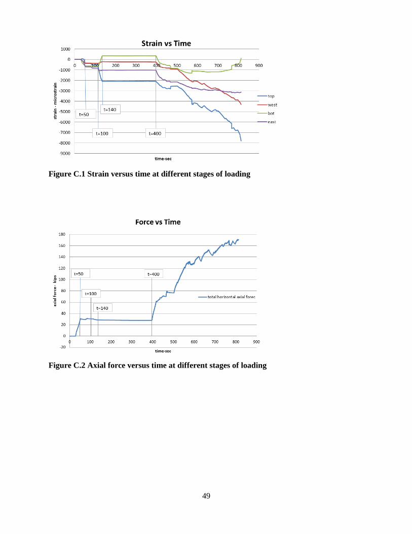
49
Figure C.1 Strain versus time at different stages of loading
Figure C.2 Axial force versus time at different stages of loading

50
Figure C.3 Moment versus time at different stages of loading
Figure C.4 Forces applied by each jack through the whole steps of loading protocol

51
Figure C.5 Measured deflection at different locations along the timber pile length