Assembly Operation Maintenance - Schneider Electric · PDF fileMedium Voltage Switching...
36
Medium Voltage Switching Devices VAH Heavy-duty vacuum circuit-breaker 12 kV to 17.5 kV Assembly Operation Maintenance No. AGS 531 271-01 Edition 08/2011 www.schneider-electric.com
Transcript of Assembly Operation Maintenance - Schneider Electric · PDF fileMedium Voltage Switching...

Medium Voltage Switching Devices
VAHHeavy-duty vacuum circuit-breaker 12 kV to 17.5 kV
Assembly Operation Maintenance No. AGS 531 271-01
Edition 08/2011
www.schneider-electric.com

Manufacturer:
Schneider Electric Sachsenwerk GmbHRathenaustrasse 2D-93055 RegensburgGermany ( +49 (0) 9 41 46 20-07 +49 (0) 9 41 46 20-418
Service:
Schneider Electric Sachsenwerk GmbHRathenaustrasse 2D-93055 RegensburgGermany( +49 (0) 9 41 46 20-07 +49 (0) 9 41 46 20-418

VAH Contents
Remarks on this manual .............................................................................4Purpose and target group........................................................................................... 4Reference documents ................................................................................................ 4Terms and symbols used............................................................................................ 4Abbreviations used..................................................................................................... 4Any questions or suggestions?................................................................................... 4
1 Safety Provisions ..............................................................................5
2 Technical details................................................................................62.1 Dimensions ..................................................................................................... 62.2 Applied standards ........................................................................................... 62.3 Environmental and operating conditions ......................................................... 62.4 Nameplate....................................................................................................... 72.5 Control and actuation units ............................................................................. 82.6 Intended use ................................................................................................. 102.7 Disposal after the end of service life ............................................................. 10
3 Overview of variants VAH............................................................... 11
4 Delivery, Storage and Transport ....................................................134.1 Delivery ......................................................................................................... 134.2 Storage.......................................................................................................... 134.3 Transport of the circuit-breaker ..................................................................... 13
5 Assembly .........................................................................................145.1 Before installation.......................................................................................... 145.2 Fixing the circuit-breaker in place ................................................................. 145.3 Fitting the partitions....................................................................................... 165.4 Interlocking further units................................................................................ 165.5 Connecting the busbars ................................................................................ 175.6 Earth connection ........................................................................................... 185.7 Connecting the control cables....................................................................... 19
6 Commissioning ...............................................................................206.1 Final steps..................................................................................................... 206.2 Checking switching functions and interlocks................................................. 20
7 Operation .........................................................................................217.1 Operator interface and operating elements................................................... 217.2 Charging the energy storing device .............................................................. 227.3 Switching operations ..................................................................................... 227.4 Fan attachment ............................................................................................ 23
8 Maintenance.....................................................................................248.1 Safety provisions........................................................................................... 248.2 Maintenance schedule .................................................................................. 258.3 Cleaning insulating components ................................................................... 268.4 Corrosion protection...................................................................................... 278.5 Condensation ................................................................................................ 278.6 Replacement of components ........................................................................ 278.7 Greasing the circuit-breaker pole and drive mechanisms............................. 278.8 Maximum admissible numbers of breaking operations of vacuum chamber 31
9 Annex ...............................................................................................339.1 Accessories................................................................................................... 339.2 Auxiliary products.......................................................................................... 339.3 Treatment of firmly screw-connected contact surfaces................................. 339.4 Specifications for screw connections ............................................................ 34
AGS 531 271-01 | Edition 08/2011 3
VAH
4 AGS 531 271-01 | Edition 08/2011
As our products are subject to continuous further development, we reserve the right to make changes regarding standards, illustrations and technical data. All dimensions specified in this manual are in millimeters.
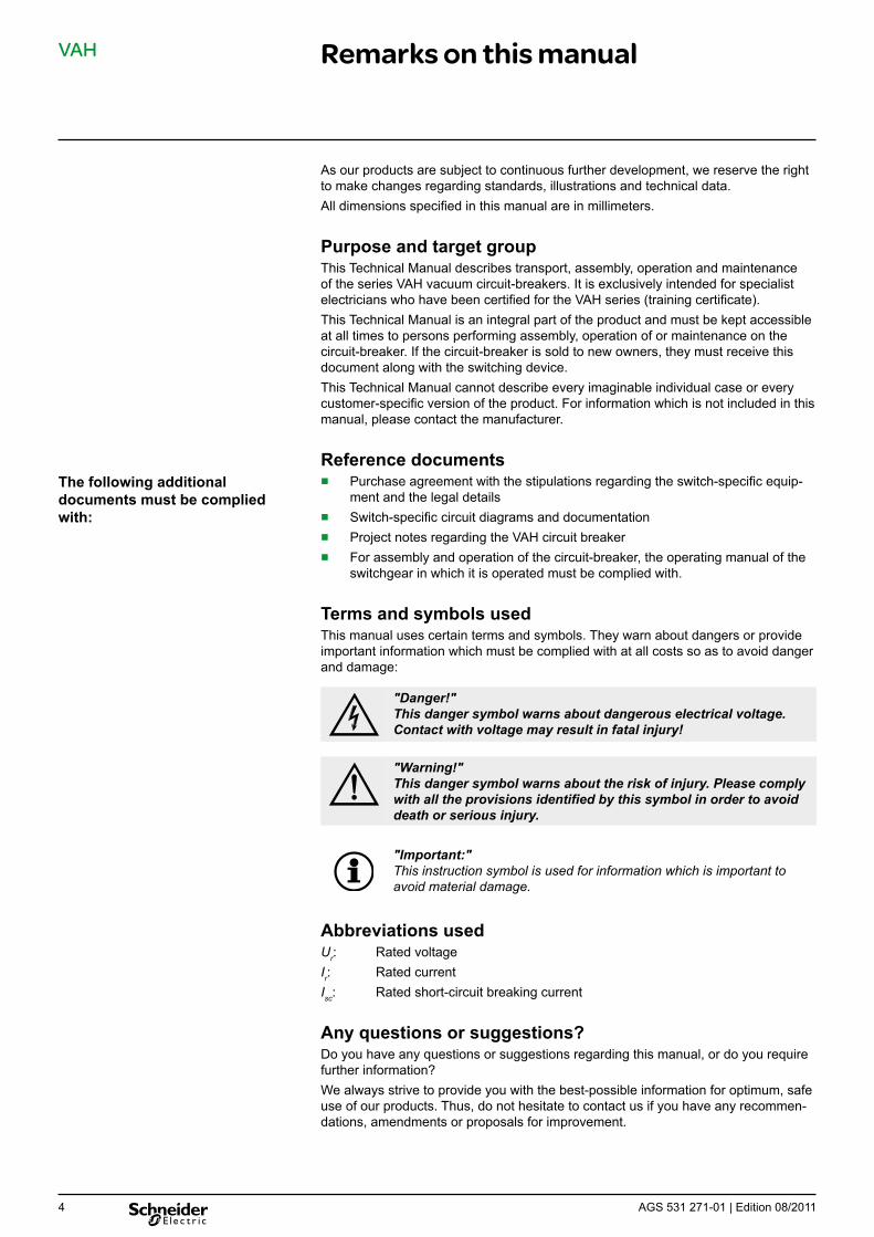
Purpose and target group This Technical Manual describes transport, assembly, operation and maintenance of the series VAH vacuum circuit-breakers. It is exclusively intended for specialist electricians who have been certified for the VAH series (training certificate). This Technical Manual is an integral part of the product and must be kept accessible at all times to persons performing assembly, operation of or maintenance on the circuit-breaker. If the circuit-breaker is sold to new owners, they must receive this document along with the switching device. This Technical Manual cannot describe every imaginable individual case or every customer-specific version of the product. For information which is not included in this manual, please contact the manufacturer.
Reference documents ■ Purchase agreement with the stipulations regarding the switch-specific equip-
ment and the legal details ■ Switch-specific circuit diagrams and documentation ■ Project notes regarding the VAH circuit breaker ■ For assembly and operation of the circuit-breaker, the operating manual of the
switchgear in which it is operated must be complied with.
Terms and symbols used This manual uses certain terms and symbols. They warn about dangers or provide important information which must be complied with at all costs so as to avoid danger and damage:
"Danger!" This danger symbol warns about dangerous electrical voltage. Contact with voltage may result in fatal injury!
"Warning!" This danger symbol warns about the risk of injury. Please comply with all the provisions identified by this symbol in order to avoid death or serious injury.
"Important:" This instruction symbol is used for information which is important to avoid material damage.
Abbreviations used U r : Rated voltage I r : Rated current I sc : Rated short-circuit breaking current
Any questions or suggestions? Do you have any questions or suggestions regarding this manual, or do you require further information? We always strive to provide you with the best-possible information for optimum, safe use of our products. Thus, do not hesitate to contact us if you have any recommen-dations, amendments or proposals for improvement.
The following additional documents must be complied with:
Remarks on this manual

VAH 1 Safety Provisions
Applicable standards and regulations:
Behaviour in case of incidents or accidents
The work described in this manual may only be performed by specialist electricians who have proved their experience with the VAH series and the applicable safety provisions. Please read the whole manual carefully before working on the circuit-breaker.
■ Common specifications for high-voltage switchgear and controlgear: IEC 62271-1
■ The locally applicable accident prevention, operating and work instructions must be complied with.
■ Installation: IEC 61936-1/HD 637 S11
■ Operation of electrical equipment: EN 50110-11
1 The national standards applicable in the country where the equipment is to be installed must be complied with.
Before performing work on the circuit-breaker, it is essential that you comply with the following instructions:
Danger! Risk of fatalities due to high voltage. Isolation from high voltage and earthing must always be ensured before performing assembly or maintenance work.
Danger! Risk of fatalities due to high supply voltage. Isolation from supply voltage must always be ensured before performing assembly or maintenance work.
Warning! Risk of injury due to movable parts in mechanical drives. For maintenance work,– isolate from supply voltage – release the circuit-breaker's energy storing device by switching it OFF-ON-OFF
In case of fire or of internal faults, toxic and caustic decomposition products may be produced. Comply with the locally applicable accident and safety provisions. In case of personal injury, take first-aid measures or cause them to be taken.
AGS 531 271-01 | Edition 08/2011 5

VAH
6 AGS 531 271-01 | Edition 08/2011
2 Technical details
2.1 Dimensions The dimensions of the individual VAH variants are specified in the selection list "Vacuum Circuit Breaker type VA, VAA, VAH, VXA, VXB, VXC". This document or additional customized dimensional drawings are available on request.
2.2 Applied standards ■ type-tested ■ dimensioned for indoor installation ■ corresponds to the requirementsfor AC switchgear for voltages above 1 kV acc.
to IEC 62271-100; ■ complies, regarding its switching capacity and insulating level, with ANSI C37....
(please enquire at the manufacturer's).
The vacuum interrupter chambers have been approved by the X-Ray Ordinance (RöV) of the Federal Republic of Germany up to a maximum voltage amounting to the rated short-time power-frequency voltage (rated power frequency withstand volt-age) defined by DIN VDE/IEC. Thus, they satisfy the conditions for operation exempt of approval up to the voltage in question according to the X-Ray Ordinance (RöV).
2.3 Environmental and operating conditions VAH circuit-breakers may only be operated under normal operating conditions acc. to IEC 62271-1. Operation under conditions deviating from these is only admissible upon consultation with and with the written approval of the manufacturer.
Ambient conditions in accordance with IEC 62271-1
Temperature class "Minus 5 indoors”1
Min./max. ambient temperature °C –5/+401
Average value over 24 hours °C ≤ 351
mean rel. air humidity: 24 hour/1 month % ≤ 95/≤ 90 Installation altitude above sea-level m ≤ 10001
1 other values available on request
Series VAH circuit-breakers are:
Type approval of vacuum interrupter chambers acc. to RöV

VAH 2 Technical details
2.4 Nameplate The type designation on the nameplate (Fig. 1, item 1) specifies essential technical data.
1
2
4
3
Fig. 1 Nameplate 1 Type designation 2 Technical data 3 Year of construction 4 Serial number
The following example shows the composition of the type designation:
VAH 17 - 63 - 50 - 40
Series VAH
Rated Voltage Ur = 17 kV
Rated short-circuit breaking current Isc = 63 kA
Rated normal current Ir = 5000 A
Pole center spacing 400 mm
When submitting enquiries to the manufacturer or ordering spare parts, the following information is required: ■ Type designation ■ Serial number ■ Year of construction
AGS 531 271-01 | Edition 08/2011 7 7

VAH
8 AGS 531 271-01 | Edition 08/20118
2 Technical details
2.5 Control and actuation units The drive is basically designed as well for manual tensioning of the energy-storing device (make spring). The drive may be equipped with further control and actuation units. ■ Push switch S21 - S25
– actuated by the energy-storing device. ■ Auxiliary switches S1
– are actuated by the switch shaft. The switching positions of the switch elements are dependent on the switch status "Make" and "Break" of the circuit-breaker.
– 12 / 16 / 20 pole versions may be supplied. – They are set in compliance with the wiring diagram. Refer to Fig. 3, page 9
regarding other settings. A number of switch elements are reserved for internal breaker-control.
■ Shunt opening releases F11-F12 ■ Shunt closing release F2 ■ Blocking coil Y1
– Blocking coils prevent the circuit breaker from being closed and opened via the push-buttons “ON“ or “OFF“, as well as manual actuation of the disconnector truck.
– If the rated supply voltage has failed or is shut off, all blocking coils are in "blocked" position.
■ Push switches S41 - S43 – S41 and S42 actuated by the button "Make" and "Break" – S43 actuated by the button "Break"
■ Motor M1 – for tensioning the energy-storing device (closing spring)
■ Anti-pumping relay (K01) – If an ON and OFF command is simultaneously and permanently present
at the circuit-breaker, the latter returns to its initial position after closing. It remains in this initial position until the ON command is issued again. This prevents continuous closing and opening (“pumping”).
■ Terminal strip (X01) Information about the power consumption of coils and the motor is available from the manufacturer. To this effect, the auxiliary voltage data is required.
Magnet coils / motor Power consumption [W]
Shunt closing release 160
Shunt opening release ca. 50
Under-voltage release without time delay 15
CT powered release 12
Blocking magnet 12
Motor 200-250
Motor tensioning time ≤ 12 s
Power consumption of magnet coils and motor:
VAH 2 Technical details
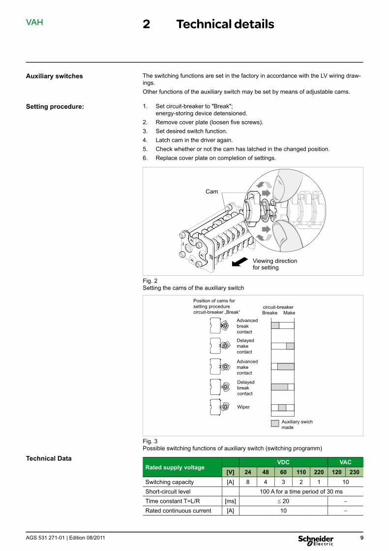
Auxiliary switches The switching functions are set in the factory in accordance with the LV wiring draw-ings. Other functions of the auxiliary switch may be set by means of adjustable cams.
Setting procedure: 1. Set circuit-breaker to "Break"; energy-storing device detensioned.
2. Remove cover plate (loosen five screws). 3. Set desired switch function. 4. Latch cam in the driver again. 5. Check whether or not the cam has latched in the changed position. 6. Replace cover plate on completion of settings.
Cam
Viewing direction for setting
Fig. 2 Setting the cams of the auxiliary switch
Position of cams for setting procedure circuitbreaker circuitbreaker „Break“ Breake Make
Advanced break contact
Delayed make contact
Advanced make contact
Delayed break contact
Wiper
Auxiliary swich made
Fig. 3Possible switching functions of auxiliary switch (switching programm)
Technical Data VDC VAC Rated supply voltage
[V] 24 48 60 110 220 120 230
Switching capacity [A] 8 4 3 2 1 10 Short-circuit level 100 A for a time period of 30 ms Time constant T=L/R [ms] ≤ 20 −
Rated continuous current [A] 10 −
AGS 531 271-01 | Edition 08/2011 99

VAH 2 Technical details
Liability Disclaimers
2.6 Intended use Series VAH vacuum circuit-breakers are exclusively intended as switching units in air-insulating medium-voltage switchgear. They may only be used in the scope of the specified standards and the switchgear-specific technical data. Any other utilization constitutes improper use and may result in dangers and damage.
The manufacturer shall not be held responsible for damage which occurs if ■ instructions in this manual are not complied with, ■ the circuit-breaker is not operated according to its intended use (see above) ■ the circuit-breaker is assembled, connected or operated improperly, ■ accessories or spare parts are used which have not been approved by the
manufacturer, ■ the circuit-breaker is converted without the manufacturer’s approval, or if inad-
missible parts are attached.
2.7 Disposal after the end of service life A material and recycling data sheet is available for disposal of the vacuum circuit-breaker unit VAH at the end of its service life; this can be provided on request. Disposal is performed by the manufacturer’s Service Center as a service subject to a fee.
AGS 531 271-01 | Edition 08/2011 10 10
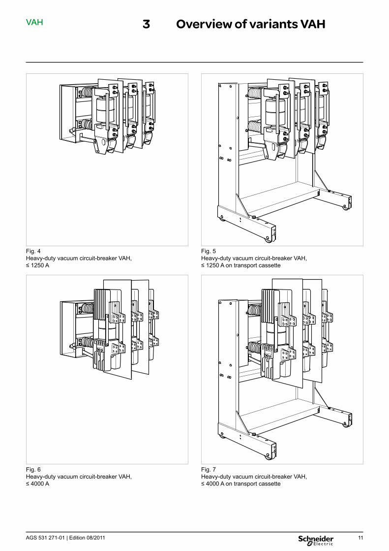
VAH 3 Overview of variants VAH
Fig. 4 Fig. 5 Heavy-duty vacuum circuit-breaker VAH, Heavy-duty vacuum circuit-breaker VAH, ≤ 1250 A ≤ 1250 A on transport cassette
Fig. 6 Fig. 7 Heavy-duty vacuum circuit-breaker VAH, Heavy-duty vacuum circuit-breaker VAH, ≤ 4000 A ≤ 4000 A on transport cassette
AGS 531 271-01 | Edition 08/2011 11

VAH 3 Overview of variants VAH
854
673 275 275
1816
501
Fig. 8Heavy-duty vacuum circuit-breaker VAH, ≤ 8000 A with fan attachment
Fig. 9Generator circuit-breaker VAH 17-63-50-40 meets the requirements of IEEE C37.013
1212 AGS 531 271-01 | Edition 08/2011

VAH 4 Delivery, Storage and Transport
4.1 Delivery – Handle shipping units carefully when unloading and unpacking them – Shipping units must be unpacked immediately after receipt. The insurance com-
pany must be notified immediately about any damage occurred in transit – On delivery, the consignment must be checked for completeness. – The manufacturer must be notified in writing about any discrepancies.
4.2 Storage The transport packaging is not intended for storage. The risk of storing the parts in packed condition shall be the consignee's responsibility!
4.3 Transport of the circuit-breaker
Warning! Make sure the crane mounting harness is strong enough to bear the weight of the circuit-breaker!
■ Transport using a forklift truck: Only transport the circuit-breaker on a pallet.
■ Transport without pallet: – on transport cassette according to Fig. 5 on page 11. – The circuit-breaker is lifted as shown in the drawing on the right. To this
effect, a crane mounting harness is required.
Fig. 10 Transport
Weights
Weight1 500 Rated current [A] ≤ 1250 ≤ 4000
[kg] 200 1 The weights of the vacuum circuit-breaker VAH are approximate and include neither packing
nor transport cassette.
AGS 531 271-01 | Edition 08/2011 13
VAH 5 Assembly
5.1 Before installation – Dimensional drawings are supplied on request. – Check the technical data on the name plate. – Check auxiliary voltage of the incorporated control and actuation units. The circuit-breaker is delivered in the position "Broken" and energy-storing device "detensioned".
Warning! Do not tension the energy-storing device before completing in-stallation. Danger of injuries.
Warning! Comply with the safety provisions in Chapter 1, page 5!
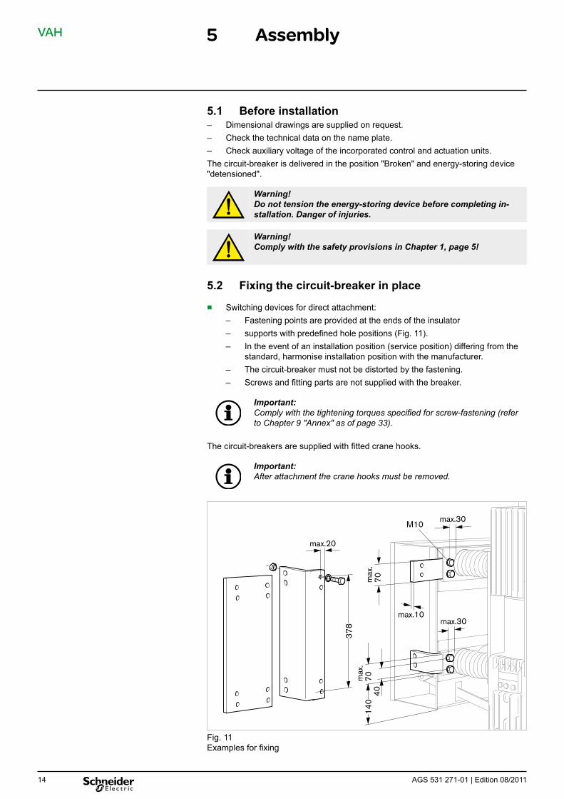
5.2 Fixing the circuit-breaker in place
■ Switching devices for direct attachment: – Fastening points are provided at the ends of the insulator – supports with predefined hole positions (Fig. 11). – In the event of an installation position (service position) differing from the
standard, harmonise installation position with the manufacturer. – The circuit-breaker must not be distorted by the fastening. – Screws and fitting parts are not supplied with the breaker.
Important: Comply with the tightening torques specified for screw-fastening (refer to Chapter 9 "Annex" as of page 33).
The circuit-breakers are supplied with fitted crane hooks.
Important: After attachment the crane hooks must be removed.
378
40
140
max.10
max
.70
max
.70
max.30M10
max.20
max.30
Fig. 11 Examples for fixing
AGS 531 271-01 | Edition 08/2011 14

VAH
15AGS 531 271-01 | Edition 08/2011 15
5 Assembly
Fig. 12 Crane hooks (remove after fitting the breaker)
■ Switching devices on transport cassette: – Four drilled holes diam. 18 mm each are provided in the transport cassette
for fastening on the floor or on rails.
100
570
1
Fig. 13 1 Fastening points in the transport cassette
VAH 5 Assembly
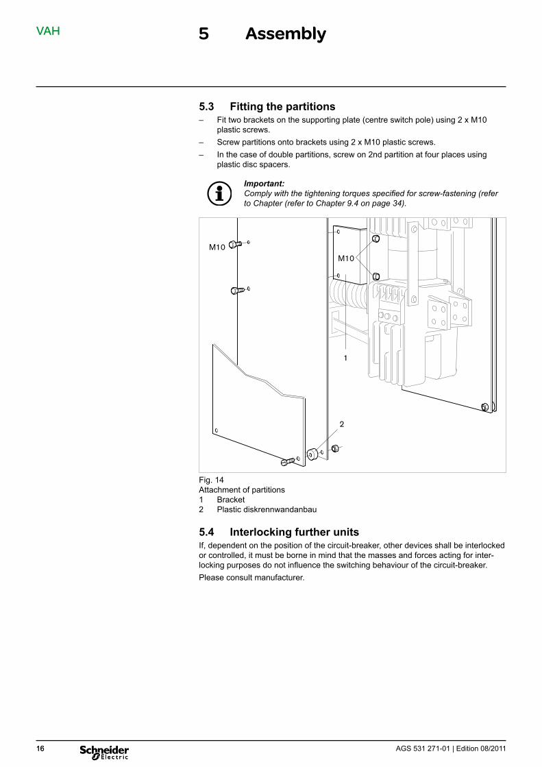
5.3 Fitting the partitions – Fit two brackets on the supporting plate (centre switch pole) using 2 x M10
plastic screws. – Screw partitions onto brackets using 2 x M10 plastic screws. – In the case of double partitions, screw on 2nd partition at four places using
plastic disc spacers.
Important: Comply with the tightening torques specified for screw-fastening (refer to Chapter (refer to Chapter 9.4 on page 34).
1
2
M10 M10
Fig. 14 Attachment of partitions 1 Bracket 2 Plastic diskrennwandanbau
5.4 Interlocking further units If, dependent on the position of the circuit-breaker, other devices shall be interlocked or controlled, it must be borne in mind that the masses and forces acting for inter-locking purposes do not influence the switching behaviour of the circuit-breaker. Please consult manufacturer.
AGS 531 271-01 | Edition 08/2011 16 16
VAH 5 Assembly
Busbar cross-sections for connection to the heavy-duty vacuum circuit-breaker VAH
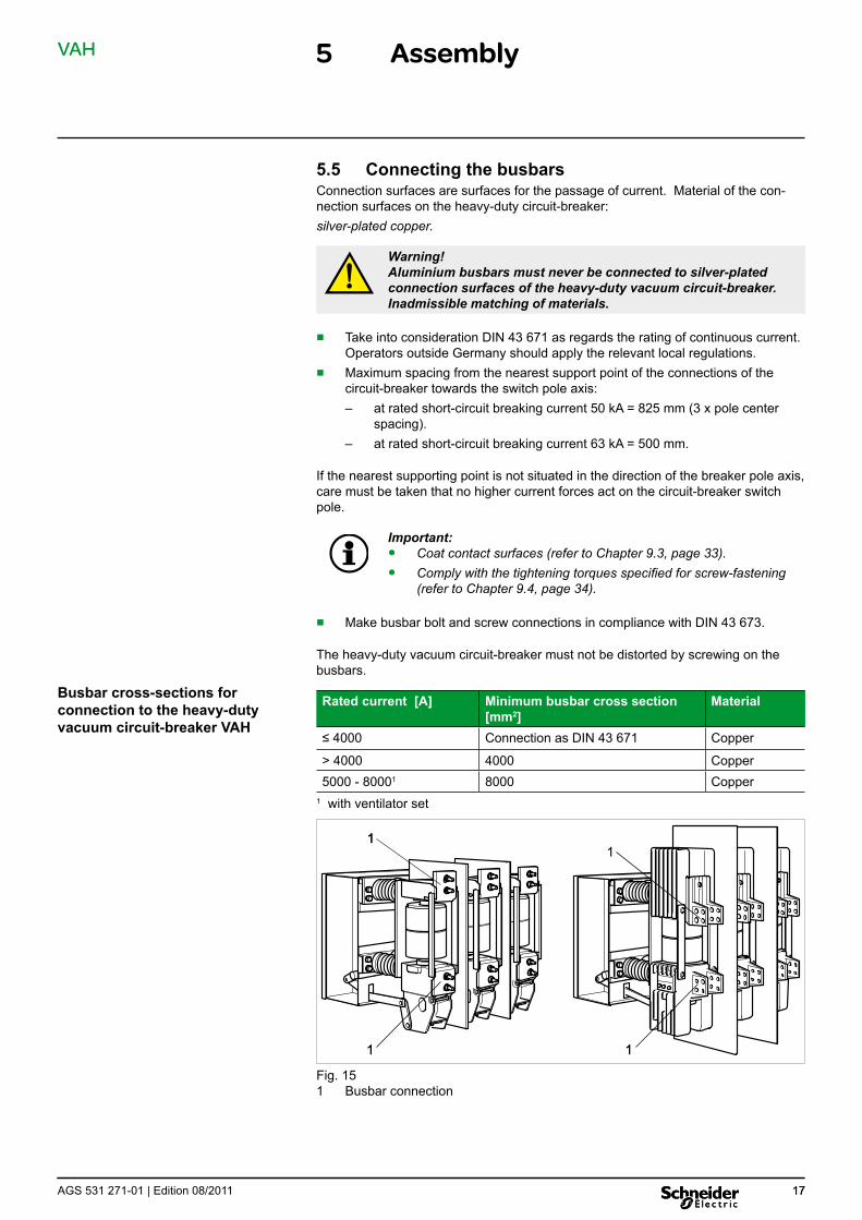
5.5 Connecting the busbars Connection surfaces are surfaces for the passage of current. Material of the con-nection surfaces on the heavy-duty circuit-breaker: silver-plated copper.
Warning!Aluminium busbars must never be connected to silver-plated connection surfaces of the heavy-duty vacuum circuit-breaker.Inadmissible matching of materials.
■ Take into consideration DIN 43 671 as regards the rating of continuous current. Operators outside Germany should apply the relevant local regulations.
■ Maximum spacing from the nearest support point of the connections of the circuit-breaker towards the switch pole axis: – at rated short-circuit breaking current 50 kA = 825 mm (3 x pole center
spacing). – at rated short-circuit breaking current 63 kA = 500 mm.
If the nearest supporting point is not situated in the direction of the breaker pole axis, care must be taken that no higher current forces act on the circuit-breaker switch pole.
Important: ● Coat contact surfaces (refer to Chapter 9.3, page 33). ● Comply with the tightening torques specified for screw-fastening
(refer to Chapter 9.4, page 34).
■ Make busbar bolt and screw connections in compliance with DIN 43 673.
The heavy-duty vacuum circuit-breaker must not be distorted by screwing on the busbars.
Rated current [A] Minimum busbar cross section Material[mm2]
≤ 4000 Connection as DIN 43 671 Copper
> 4000 4000 Copper 5000 - 80001 8000 Copper
1 with ventilator set
111
1 11 1
Fig. 15 1 Busbar connection
AGS 531 271-01 | Edition 08/2011 1717
VAH
18 AGS 531 271-01 | Edition 08/201118
5 Assembly
5.6 Earth connection (Connect station earth to the earth connection of the circuit-breaker.) ■ Choose cross-section and material of the earth conductor in compliance with
DIN VDE 0141 or national installation specification.
Important: ● Coat contact surfaces (refer to Chapter 9.3, page 33 ). ● Comply with the tightening torques specified for screw-fastening
(refer to Chapter 9.4, page 34).
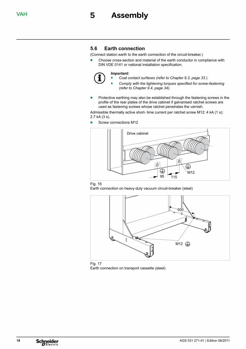
■ Protective earthing may also be established through the fastening screws in the profile of the rear plates of the drive cabinet if galvanised ratchet screws are used as fastening screws whose ratchet penetrates the varnish.
Admissible thermally active short- time current per ratchet screw M12: 4 kA (1 s); 2.7 kA (3 s). ■ Screw connections M12
95 115 M12
Drive cabinet
Fig. 16 Earth connection on heavy-duty vacuum circuit-breaker (steel)
500
M12
Fig. 17 Earth connection on transport cassette (steel)

VAH 5 Assembly
5.7 Connecting the control cables Connection by means of (Fig. 18): – plug or – terminal strip in the drive cabinet.
1
2
Fig. 18 External control cables 1 Opening for control and auxiliary cables 2 Plug alternatively Externe Steuerleitungen
On connection by terminal strip ■ deinstall cover plate (five screws). ■ connect the external control cables through the terminal strip and lay them to
the outside through the opening in the drive cabinet.
The following may be connected: ■ flexible wires up to 1.5 mm2 (only on connection by plug) ■ solid single wires up to 2.5 mm2.
The binding wiring diagram is situated as adhesive circuit diagram on the inner side of the cover plate. ■ If additional control cables are installed in the drive cabinet, sufficient spacing to
moving parts of the drive must be provided. ■ Reinstall cover plate after the external control cables have been connected.
Important: Comply with the tightening torques specified for screw-fastening (refer to Chapter 9.4 on page 34).
AGS 531 271-01 | Edition 08/2011 19 19

VAH 6 Commissioning
6.1 Final steps
Danger! Risk of fatalities due to high voltage. All active parts must be earthed.
Checking assembly ■ Check securing bolts. ■ Check the conductor bars’ screw connections using a torque wrench. ■ Check the screw connections of the earth terminal. ■ Check wiring laid on site.
Damaged paint Minor damage to the paint can be repaired using a commercially available touch-up pen (standard colour RAL 7044 or corresponding colour) (see Chapter 9.2 “Auxiliary products” on page 33).
Inspection ■ Check the circuit-breaker for damage which might be due to transport or as-sembly work.
■ Compare the data on the nameplate (see Chapter 2.4 on page 7) to the re-quired rating specifications.
■ Check rated supply voltage of control and operating devices. ■ Check surfaces of insulating components for impurities. If necessary, clean (see
Chapter 8.3 on page 26).
6.2 Checking switching functions and interlocks
Danger! The high-voltage supply must not be connected. All active parts must be earthed.
Important: ● For switching operations, comply with Chapter 7 “Operation” as of
page 21. ● In case supply voltage is not available,
– blocking coils (optional; lock circuit-breaker button in discon-nected position) are in locked position, thus blocking manual switching operations;
– there is a dropped-out undervoltage release in the circuit-breaker (optional).
● The energy-storing device of the circuit-breaker drive is charged autonomously as soon as the supply voltage is applied.
1. Charge energy-storing device using the crank. Check the spring position indicator.
2. Switch circuit-breaker on and off several times by hand. Check position indicator.
3. Check electrical functions of control and operating devices. – Apply auxiliary voltage – Perform switching operations and check for proper working order and the
function of the interlocks by actuating the shunt release. – Watch position indicator.
4. Check interlocks between circuitbreaker and other devices.
AGS 531 271-01 | Edition 08/2011 20

VAH 7 Operation
7.1 Operator interface and operating elements
3
4
2
1
7
6
5
Fig. 19 Operating elements 1 Name plate 2 Position indicator, energy-storing device (charged / released) 3 ON button 4 OFF button 5 Operating counter 6 Opening for crank to charge the enrgy-storing device 7 Position indicator ON / OFF
Position indicators on circuit-breaker and possible operating sequences
Pos. Position indicator
Energy-storing device (Closing spring)
Position indicator
ON/OFF ("Close/ Trip") Switch position
Opening spring Possible operating sequence
1 released OFF released none
2 charged OFF released, is charged via C C - O
3 released ON charged O
4 charged ON charged, is re-charged via C O - C - O
C = Closing (ON) O = Opening (OFF)
AGS 531 271-01 | Edition 08/2011 21
VAH 7 Operation
Initial position:
Closing (ON)
Opening (OFF)
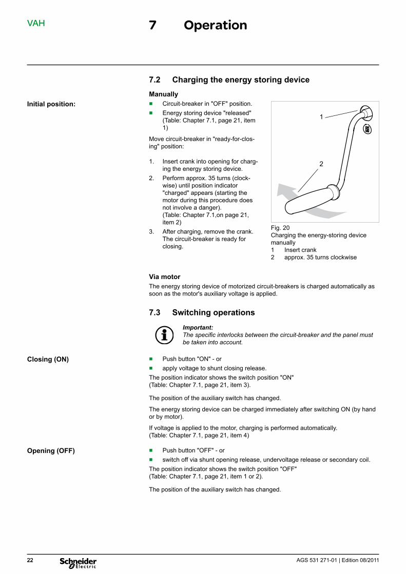
7.2 Charging the energy storing device
Manually ■ Circuit-breaker in "OFF" position. ■ Energy storing device "released"
(Table: Chapter 7.1, page 21, item 1)
Move circuit-breaker in "ready-for-clos-ing" position:
1. Insert crank into opening for charg-ing the energy storing device.
2. Perform approx. 35 turns (clock-wise) until position indicator "charged" appears (starting the motor during this procedure does not involve a danger). (Table: Chapter 7.1,on page 21, item 2)
3. After charging, remove the crank. The circuit-breaker is ready for closing.
1
2
Fig. 20 Charging the energy-storing device manually 1 Insert crank 2 approx. 35 turns clockwise
Via motor The energy storing device of motorized circuit-breakers is charged automatically as soon as the motor's auxiliary voltage is applied.
7.3 Switching operations
Important: The specific interlocks between the circuit-breaker and the panel must be taken into account.
■ Push button "ON" - or ■ apply voltage to shunt closing release. The position indicator shows the switch position "ON" (Table: Chapter 7.1, page 21, item 3).
The position of the auxiliary switch has changed.
The energy storing device can be charged immediately after switching ON (by hand or by motor).
If voltage is applied to the motor, charging is performed automatically. (Table: Chapter 7.1, page 21, item 4)
■ Push button "OFF" - or ■ switch off via shunt opening release, undervoltage release or secondary coil. The position indicator shows the switch position "OFF" (Table: Chapter 7.1, page 21, item 1 or 2).
The position of the auxiliary switch has changed.
AGS 531 271-01 | Edition 08/2011 22 22
VAH 7 Operation
Fan operation:
Air flow monitor:
Measures in case of failure of a fan:
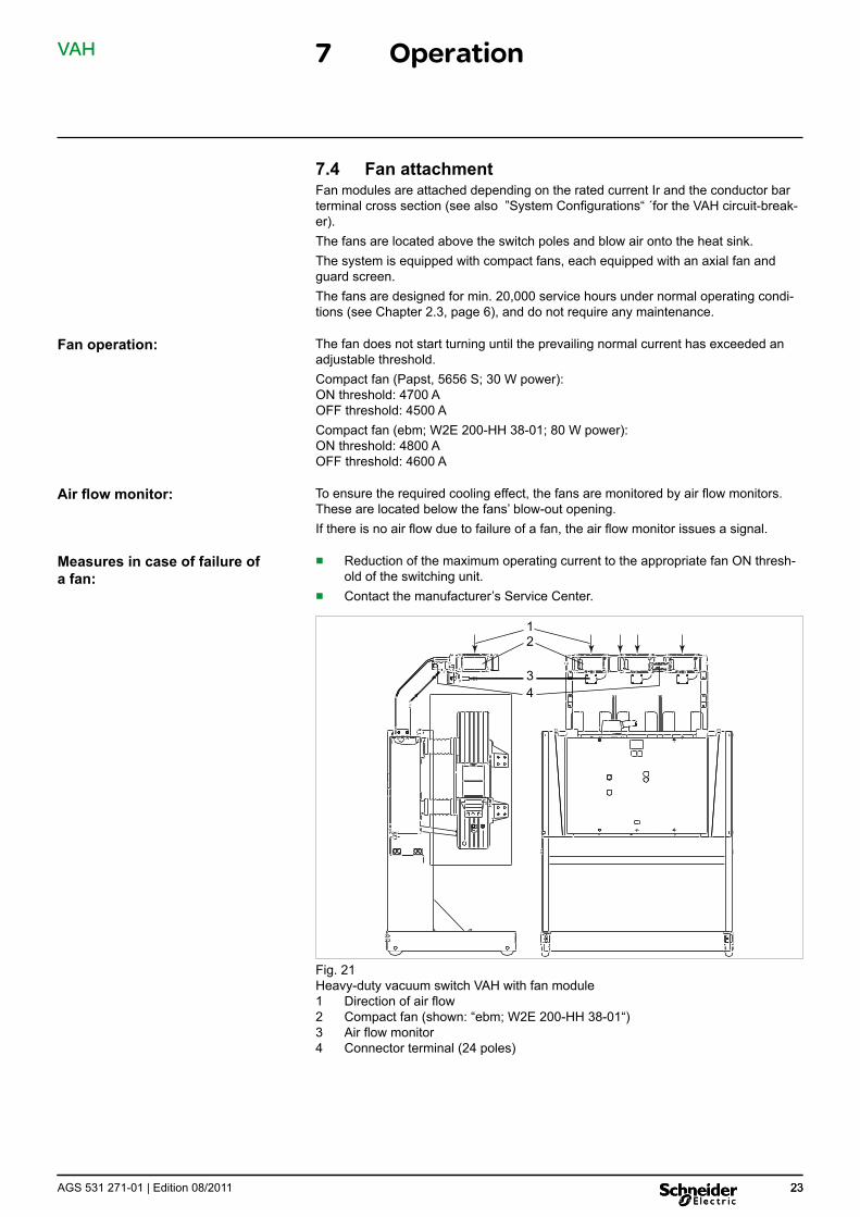
7.4 Fan attachment Fan modules are attached depending on the rated current Ir and the conductor bar terminal cross section (see also ”System Configurations“ ´for the VAH circuit-break-er). The fans are located above the switch poles and blow air onto the heat sink. The system is equipped with compact fans, each equipped with an axial fan and guard screen. The fans are designed for min. 20,000 service hours under normal operating condi-tions (see Chapter 2.3, page 6), and do not require any maintenance.
The fan does not start turning until the prevailing normal current has exceeded an adjustable threshold. Compact fan (Papst, 5656 S; 30 W power): ON threshold: 4700 A OFF threshold: 4500 A Compact fan (ebm; W2E 200-HH 38-01; 80 W power): ON threshold: 4800 A OFF threshold: 4600 A
To ensure the required cooling effect, the fans are monitored by air flow monitors. These are located below the fans’ blow-out opening. If there is no air flow due to failure of a fan, the air flow monitor issues a signal.
■ Reduction of the maximum operating current to the appropriate fan ON thresh-old of the switching unit.
■ Contact the manufacturer’s Service Center.
1 2
3 4
Fig. 21 Heavy-duty vacuum switch VAH with fan module 1 Direction of air flow 2 Compact fan (shown: “ebm; W2E 200-HH 38-01“) 3 Air flow monitor 4 Connector terminal (24 poles)
AGS 531 271-01 | Edition 08/2011 2323

VAH 8 Maintenance
8.1 Safety provisions Maintenance and cleaning work may only be performed by specialist electricians who have been certified by the manufacturer for maintenance work on the series VAH vacuum circuit-breakers and who are familiar with the appropriate safety provi-sions.
Warning! Comply with the safety provisions in Chapter 1, page 5!
Warning! The circuit-breaker must not be disassembled for maintenance work! “Use in line with the intended purpose” jeopardised (see Chapter 2.6 on page 10).
Safety precautions: 1. On principle, the 5 safety rules applicable for electrical engineering must be
complied with before maintenance work on the circuit-breaker is started. These rules apply for all live parts: ■ Isolating from the power supply ■ Securing from reclosing ■ Ensuring zero voltage ■ Earthing and short-circuiting ■ Covering or cordoning off adjacent live components.
2. Switch off the auxiliary voltage for the circuit-breaker drive and secure it against reclosing.
3. Release the energy-storing device by performing the corresponding operating sequence on the circuit-breaker: OFF - ON - OFF (see Chapter 7, as of page 21).
AGS 531 271-01 | Edition 08/2011 24
VAH
25AGS 531 271-01 | Edition 08/2011 25
8 Maintenance
8.2 Maintenance schedule Series VAH vacuum circuit-breakers are indoor switching devices designed for nor-mal operating conditions in acc. with IEC 62271-1.
It is recommended to check the circuit-breakers visually at regular intervals depend-ing on the strain they are subject to during operation and in accordance with national regulations.
Important: In case of frequent condensation or air pollution (dust, smoke or cor-rosive gases), the maintenance intervals must be adapted to the actual conditions.
A visual inspection includes a complete check of the circuit-breaker for contamina-tion, condensation and damage, to be performed by certified staff.
If there are signs of contamination or condensation, the circuit-breakers must be cleaned in an expert manner (see Chapters 8.3 and 8.4 on page 27) and subse-quently the drives, interlocks and position indicators checked for proper functioning (see Chapter 7 as of page 21).
If damage is detected, it must be repaired immediately, or components replaced. In case of ambiguities or irregularities, please contact the manufacturer’s Service Center immediately.
Inspection
Maintenance
Overhauling
Maintenance interval Maintenance work Qualification / Work performed by
After 20 years ■ Clean and grease circuit-breaker (see Chapter 8.3, page 26 and Chapter 8.7, page 27)
■ Perform several switching tests
Staff who have been certified for this work
After 10 000 operating cycles
Revision of the circuit-breaker
Manufacturer’s Service Center
once the max. admissible number of breaking opera-tions for the vacuum cham-bers has been reached (see Chapter 8.8, page 31)
Replacement of circuit-breaker poles

VAH
The following parts must be cleaned:
Use a dry cleaning cloth in case of slight soiling:
Use cleaning agents in case of severe soiling:
8 Maintenance
8.3 Cleaning insulating components To secure the specified insulating level, the insulators must be clean.
■ post insulators ■ operating rods ■ connection plates ■ ceramic of the vacuum switching chambers ■ partitions Moreover, general cleanliness of the circuit-breaker and of its external parts should be ensured.
Clean by means of a dry, lint-free cloth. Depending on quantity of dirt collected, replace cloth as often as necessary.
Cleaning agent 1 liter can, Order no. S 008152 The use of other cleaning agents is not admissible. ■ Wear protective gloves ■ Use the cleaning agent according to the manufacturer’s instructions ■ Soak the cloth thoroughly and wipe the insulating components. Keep duration
of contact as short as possible. ■ Expose the cleaned surface to the air for at least 2 hours.
Fig. 22 VAH circuit-breaker Insulating components which must be cleaned at regular intervals
2626 AGS 531 271-01 | Edition 08/2011
VAH 8 Maintenance
8.4 Corrosion protection Drive mechanisms and covers have a long-term protection against corrosion. Any damage to the paint, scratches and other damage must be remedied immediately to avoid corrosion. Contact the manufacturer’s Service Center.
8.5 Condensation To ensure the specified insulating level, the VAH circuit-breaker – especially its insu-lating components – must not be exposed to condensation.
Measures to take in case of condensation: 1. If condensation of the circuit-breaker is detected, the switching device must be
cleaned according to Chapter 8.3, page 26 . 2. Installation or inspection of the appropriate heating. It must provide a sufficient
heating performance to prevent condensation on the circuit-breaker.
8.6 Replacement of components Drive or live high-voltage components may be replaced as required. The following data on the nameplate are relevant for replacement of components or in case of any queries (see also Chapter 2.4, page 7):■ Type designation ■ Serial number ■ Year of construction If you have any queries regarding replacement of components, please contact the manufacturer’s Service Center.
8.7 Greasing the circuit-breaker pole and drive mechanisms
Important: The following elements must not be lubricated: ● charging gears ● motor ● ball-bearings and sliding bearings ● auxiliary Make release ● auxiliary Break release ● push switch Make-Break ● push switch "Energy-storing device" ● auxiliary switches ● tappets of all release coils
AGS 531 271-01 | Edition 08/2011 27 27

VAH
Grease switch poles:
8 Maintenance
O Liquid lubricant FL Order no. S 008 153, on bearings, articulated joints and guides. Apply liquid lubricant in drops (oil can, drip-feed oiler) in the bearing gap. Through capillary action the liquid lubricant runs between the bearing surfaces. Use extension pipe or spray at inaccessible lubrication points.
Fig. 23 Circuit-breaker pole VAH 1250 A / 2500 A / 3150 A, lower section, lubrication points
Fig. 24 Circuit-breaker pole VAH 4000 A / 8000 A, lower section, lubrication points
2828 AGS 531 271-01 | Edition 08/2011

VAH
Removing the operating panel:
Once lubrication of the drive mechanism is complete:
Lubrication the drive:
8 Maintenance
Tool: TORX screwdriver, size T25 / slotted screwdriver Remove the 5 x M5 screws on the front and remove the operating panel.Put operating panel and screws in a safe place for subsequent reassembly.
1. Put the operating panel back on. Tightening torque for the securing bolts: 3.8 - 5.6 Nm.
2. Put circuit-breaker into operation again according to Chapter 6, as of page 20 “Commissioning”.
1
1
1
1
Fig. 25 Frontplate of VAH circuit-breaker 1 Securing bolts
Fig. 26Lubrication points in the drive (overview drawing see Fig. 27, page 30)
AGS 531 271-01 | Edition 08/2011 29 29

VAH 8 Maintenance
Lubrication procedure:
1
2
3
6
Fig. 27 Lubrication points in the drive Synthetic lubricant Liquid lubricant FL
Synthetic lubricant Order no. ST 312-111-835, on sliding surfaces Clean lubrication points, e.g. with a non-fluffy cotton cloth or soft brush and deter-gent (use little, moisten only lubrication points). Apply a thin film of synthetic lubri-cant.
Liquid lubricant FL Order no. S 008 153 on bearings, articulated joints and guides Apply the liquid lubricant in drops (oil can, drip-feed lubricator) in the bearing gap. The liquid lubricant runs between the bearing surfaces through capillary action. Use extension pipe or spray at inaccessible points.
11 10
9
8
7
4 5
3030 AGS 531 271-01 | Edition 08/2011
VAH 8 Maintenance
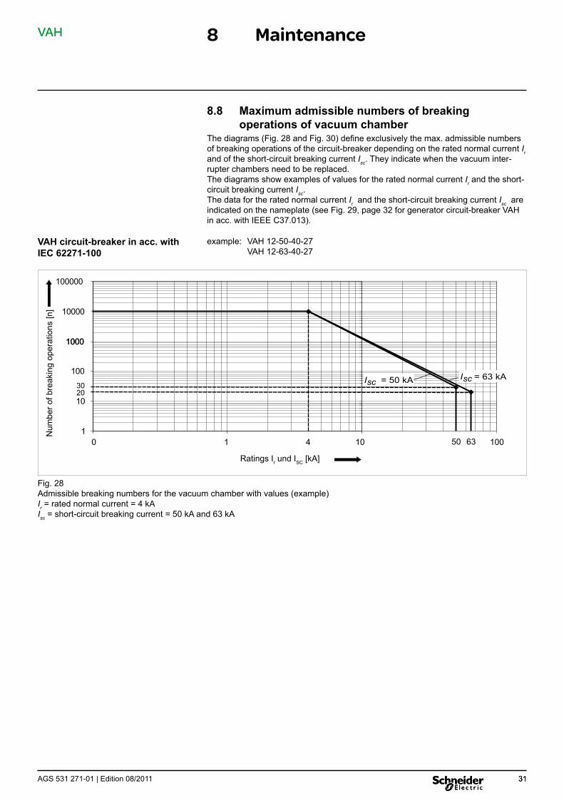
VAH circuit-breaker in acc. with IEC 62271-100
8.8 Maximum admissible numbers of breaking operations of vacuum chamber
The diagrams (Fig. 28 and Fig. 30) define exclusively the max. admissible numbers of breaking operations of the circuit-breaker depending on the rated normal current Ir and of the short-circuit breaking current Isc. They indicate when the vacuum inter-rupter chambers need to be replaced. The diagrams show examples of values for the rated normal current Ir and the short-circuit breaking current Isc . The data for the rated normal current Ir and the short-circuit breaking current Isc are indicated on the nameplate (see Fig. 29, page 32 for generator circuit-breaker VAH in acc. with IEEE C37.013).
example: VAH 12-50-40-27 VAH 12-63-40-27
1
100
1000
10000
100000
0 104
10 20 30
1000
1 100
Num
ber o
f bre
akin
g op
erat
ions
[n]
6350
Ratings Ir und ISC [kA]
I = 50 kAsc I = 63 kAsc
Fig. 28 Admissible breaking numbers for the vacuum chamber with values (example) I = rated normal current = 4 kA rIsc = short-circuit breaking current = 50 kA and 63 kA
AGS 531 271-01 | Edition 08/2011 31 31
VAH 8 Maintenance
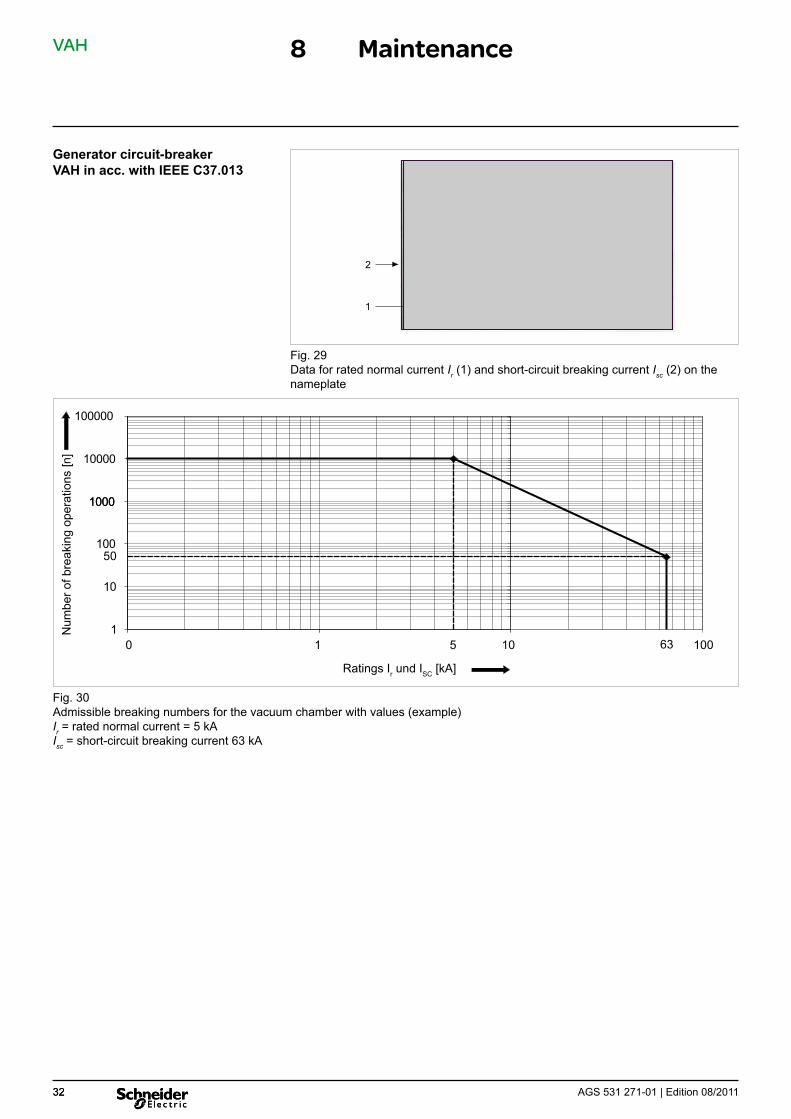
Generator circuit-breaker VAH in acc. with IEEE C37.013
1
2
Fig. 29 Data for rated normal current Ir (1) and short-circuit breaking current Isc (2) on the nameplate
1
100
1000
10000
100000
0 105
10
50
1000
1 10063
Ratings Ir und ISC [kA]
Num
ber o
f bre
akin
g op
erat
ions
[n]
Fig. 30 Admissible breaking numbers for the vacuum chamber with values (example) I = rated normal current = 5 kA rIsc = short-circuit breaking current 63 kA
AGS 531 271-01 | Edition 08/2011 32 32
VAH 9 Annex
9.1 Accessories
Designation Order no. Manual crank AGS 617 810-01
9.2 Auxiliary products The auxiliary products are available from the manufacturer. The use of alternative auxiliary products is not permissible.
Warning! Risk of injury if these products are handled improperly. Observe the safety data sheets of the manufacturers of the auxil-iary products.
Designation Order no. Synthetic lubricant, 0,5-kg can
Liquid lubricant FL, 0,5-kg can
Cleaning agent, 1-l can
Touch-up pen RAL 7044, silk-grey, 50 ml Touch-up pen, special paint (specify colour shade)
ST 312-111-835
S 008 153
S 008 152
S 009 561 S 009 562
9.3 Treatment of firmly screw-connected contact surfaces
Important: ■ Caution when handling bars insulated by heat-shrinkable sleeves:
The heat-shrinkable sleeve must not get into contact with contact grease (swelling).
■ Contact areas coated with contact grease should not be touched, if possible.
1. Contact areas must be subjected to preliminary treatment before screw-fasten-ing (see Table below)
2. Immediately after the pre-treatment, coat the contact surfaces with contact grease, so that the space between the contact surfaces is completely filled once the screws have been connected.
Material of contact surfaces Pre-treatment Silver-plated Cleaning1
Nickel-plated Remove passivation layer4
Copper or copper alloy Clean1, expose metallic surface2
Aluminium Clean1, expose metallic surface2
Steel Clean1, expose metallic surface2
Zinc-plated steel Remove passivation, not, however, the zinc layer3
Hot-galvanized sheet-metal Clean1, passivation need not be removed 1 Clean by means of lint-free cloth; use cleaning agent in case of serious con-
tamination 2 Expose metallic surface
- by treating the entire surface with emery cloth or a rotating grinding tool (grain size 100 or 80) or - using a wire brush which is clearly marked for use exclusively for aluminium or exclusively for copper
3 using a brass brush, steel brush 4 rub slightly by hand using Scotchbrite abrasive agent (Ni layer must not be
reduced)
AGS 531 271-01 | Edition 08/2011 33
VAH 9 Annex
9.4 Specifications for screw connections
Important: ■ The threads of screws and bolts must generally not be pre-trea-
ted! ■ Max. tolerance for the effective tightening torques: ±15% ■ The nut must correspond in strength to the grade of the screw/bolt
used or be of better quality.
General screw connections
Grade or material
Screw/bolt Plastics ≥ 8.8 ≤ 10.9 Self-locking screw
≥ 8.8 Thread Ø Tightening torques [Nm]
M 4 0.25 2.6
M 5 0.5 5.0 7.0
M 6 0.8 8.8 12.3
M 8 1.8 21.0 30.0
M 10 3.5 42.0 59.0
M 12 6.0 70.0 97
M 16 12 170
M 20 330
Screw fastening for power Screw connection for terminal transmission strips
Screws and bolts: Grade ≥ 8.8
Thread Ø Tightening torques [Nm]Thread Ø Tightening
torques [Nm]
Conductor material: copper
M 2.5 (M 2.6) 0.5 M 6 6.5 M 3 0.7 M 8 17 M 3.5 1.0 M 10 35 M 4 1.5 M 12 68 M 5 2.5 M 16 135
AGS 531 271-01 | Edition 08/2011 34 34


© S
chne
ider
Ele
ctric
201
1 –
All
right
s re
serv
ed to
this
tech
nica
l man
ual.
Rep
rodu
ctio
n an
d m
akin
g av
aila
ble
of th
is te
chni
cal m
anua
l, or
ext
ract
s, to
third
par
ties
are
proh
ibite
d.
Onl
y in
tegr
al re
prod
uctio
n of
this
tech
nica
l man
ual i
s pe
rmitt
ed w
ith th
e w
ritte
n pe
rmis
sion
from
Sch
neid
er E
lect
ric. E
lect
roni
c co
pies
in e
.g. P
DF-
form
at o
r sca
nned
ver
sion
have
the
stat
us “f
or in
form
atio
n on
ly” .
The
onl
y va
lid v
ersi
on o
f thi
s te
chni
cal m
anua
l is
alw
ays
encl
osed
dire
ctly
to th
e pr
oduc
t in
ques
tion
by th
e fa
ctor
y.
Schneider Electric As our products are subject to continuous development, we reserve the 35, rue Joseph Monier right to make changes regarding the standards, illustrations and technical CS 30323 data described in this Technical Manual. For any requests, please contact 92506 Rueil-Malmaison Cedex, France the address given below.
RCS Nanterre 954 503 439 Schneider Electric Sachsenwerk GmbH Capital social 896 313 776 € Rathenaustrasse 2 www.schneider-electric.com D-93055 Regensburg, Germany
( +49 (0) 9 41 46 20-0 AGS 531 271-01 | 08/2011 7 +49 (0) 9 41 46 20-418