Assembly of the Electronics - storage.googleapis.com · Assembly of the Electronics Discover and...
12
2 Assembly of the Electronics Discover and share everything you can do at diwo.bq.com
Transcript of Assembly of the Electronics - storage.googleapis.com · Assembly of the Electronics Discover and...
2
Assembly of theElectronics
Discover and share everything you can do atdiwo.bq.com

List of components for the electronics
2 x Laser
1 x Logitech® C270 camera
1 x bq ZUM BT-328 controller board
1 x bq ZUM SCAN power shield
1 x Stepstick Drivers A4988 4 layers
2 x Printed piece laser cable tray: 80 mm
1 x Printed piece motor cable tray: 240 mm
1 x Printed piece electronics cover
1 x Micro-USB cable
1 x Power supply 12 V 1.5 A
1 x Methacrylate front pattern
1 x Printed piece pattern support
1 x Checkerboard pattern sticker
2 x M3 x 10 mm black screw - DIN 912 Class 8.8
2 x M3 black nut - DIN 934 Class 8
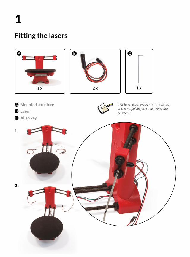
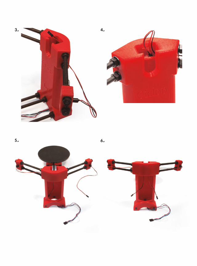
Fitting the lasers
Mounted structure
Laser
Allen key
A B
A
B
1
2 x1 x
2
Tighten the screws against the lasers, without applying too much pressure on them. C
1
1 x
C
3 4
5 6
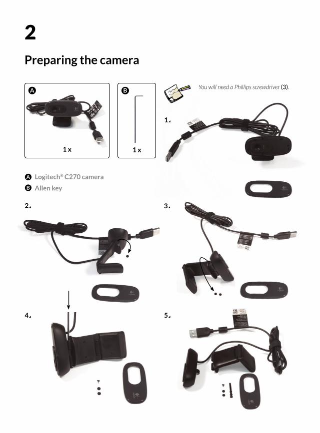
Preparing the camera
Logitech® C270 camera
Allen key
A
A
1 x
2
2 3
4 5
1
1 x
B
B
You will need a Phillips screwdriver (3).

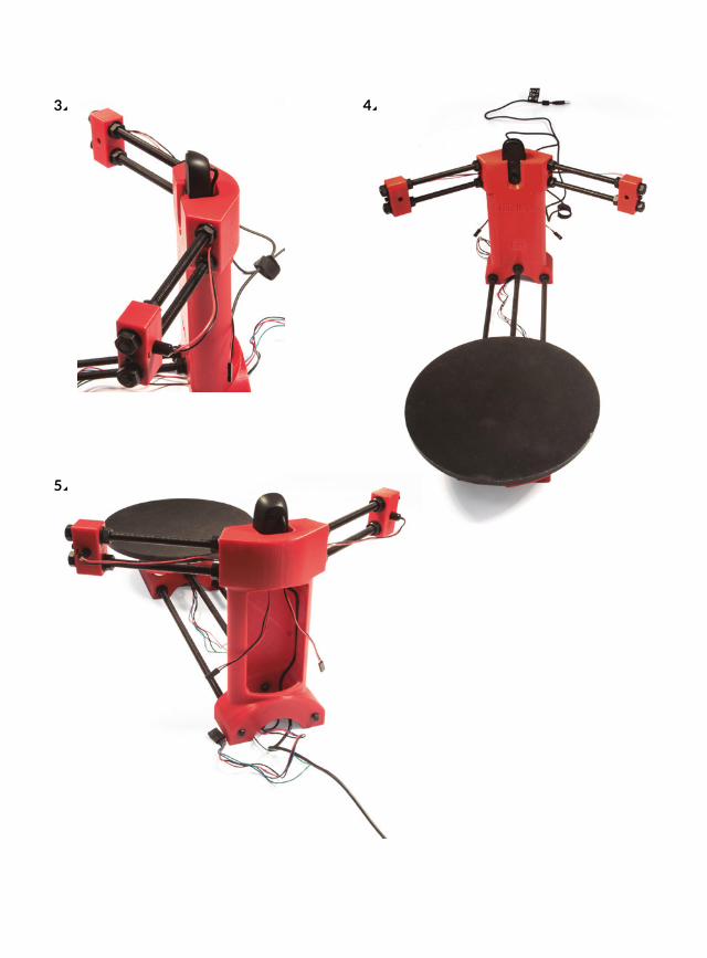
Fitting the camera
A
1 2
3
1 x
B
1 x
Logitech® C270 camera (attachments removed)
Ensemble from Step 1
A
B
3 4
5
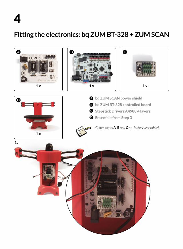
4Fitting the electronics: bq ZUM BT-328 + ZUM SCAN
1 x
bq ZUM SCAN power shield
bq ZUM BT-328 controlled board
Stepstick Drivers A4988 4 layers
Ensemble from Step 3
A B
A
1 x 1 x
C
B
C
1
D
Components A, B and C are factory-assembled.
D
1 x
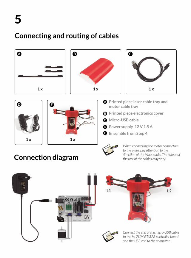
5Connecting and routing of cables
1 x
Printed piece laser cable tray and motor cable tray
Printed piece electronics cover
Micro-USB cable
Power supply 12 V 1.5 A
Ensemble from Step 4
A B
A
1 x 1 x
C
Connection diagram
D
1 x
B
C
D
L2L1
1 x
E
E
When connecting the motor connectors to the plate, pay attention to the direction of the black cable. The colour of the rest of the cables may vary.
Connect the end of the micro-USB cableto the bq ZUM BT-328 controller board and the USB end to the computer.
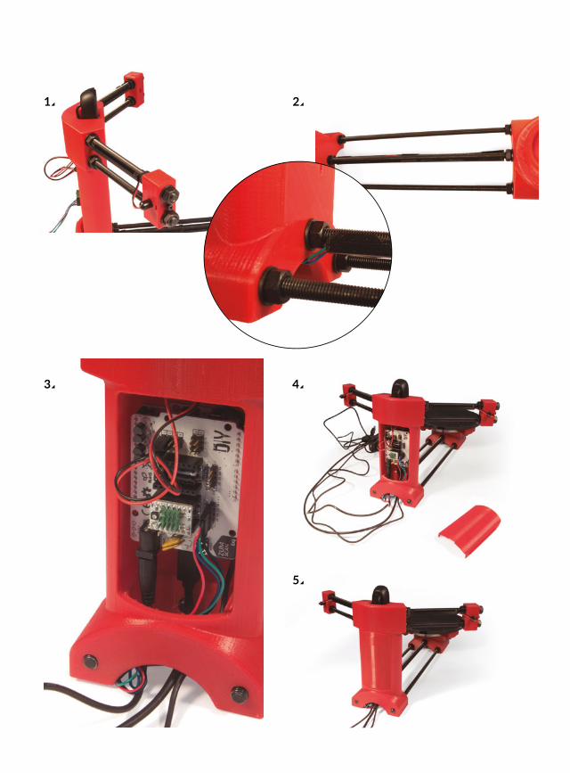
1 2
3
5
4
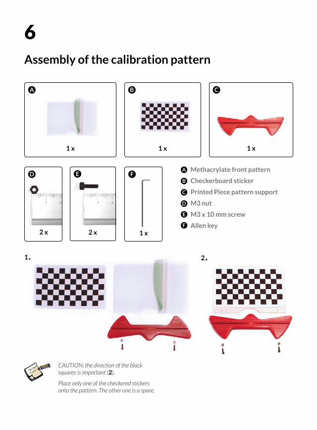
6Assembly of the calibration pattern
Methacrylate front pattern
Checkerboard sticker
Printed Piece pattern support
M3 nut
M3 x 10 mm screw
Allen key
A
A
1 x 1 x
B
B
C
2
2 x
E
D
E
F
1 x
F
1
1 x
C
CAUTION: the direction of the black squares is important (2).
Place only one of the checkered stickers onto the pattern. The other one is a spare.
D
2 x

You have now finished assembling your Ciclop. Before you start to scan, you will need to install the software. Follow the installation guidelines and conditions recommended at:
www.bq.com/ciclop
3