Assembly Instructions for STS-95 payload€¦ · Assembly Instructions for STS-95 payload ... The...
16
© 2007 Assembly Instructions for STS-95 payload (John Glenn’s Return to Space)
Transcript of Assembly Instructions for STS-95 payload€¦ · Assembly Instructions for STS-95 payload ... The...

© 2007
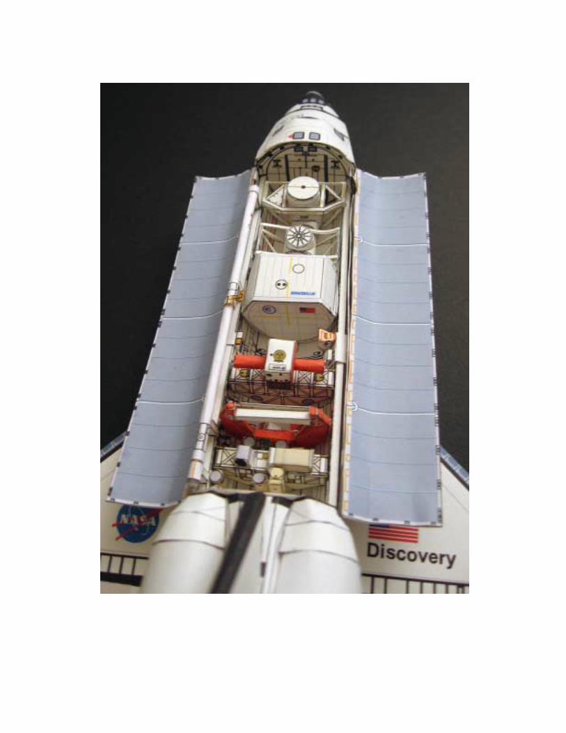
Assembly Instructions for STS-95 payload
(John Glenn’s Return to Space)
Building the Transfer tunnel and External Airlocks.
Make the first airlock as photo on the left. Right photo shows the support structure that will hold the airlock in place. Notice the position of the lateral beams.
Photos show the position of the other elements when building this airlock. Note how the lateral thin parts are glued at the bottom of the airlock System. The second external airlock is glued to the first one as left photo indicates.
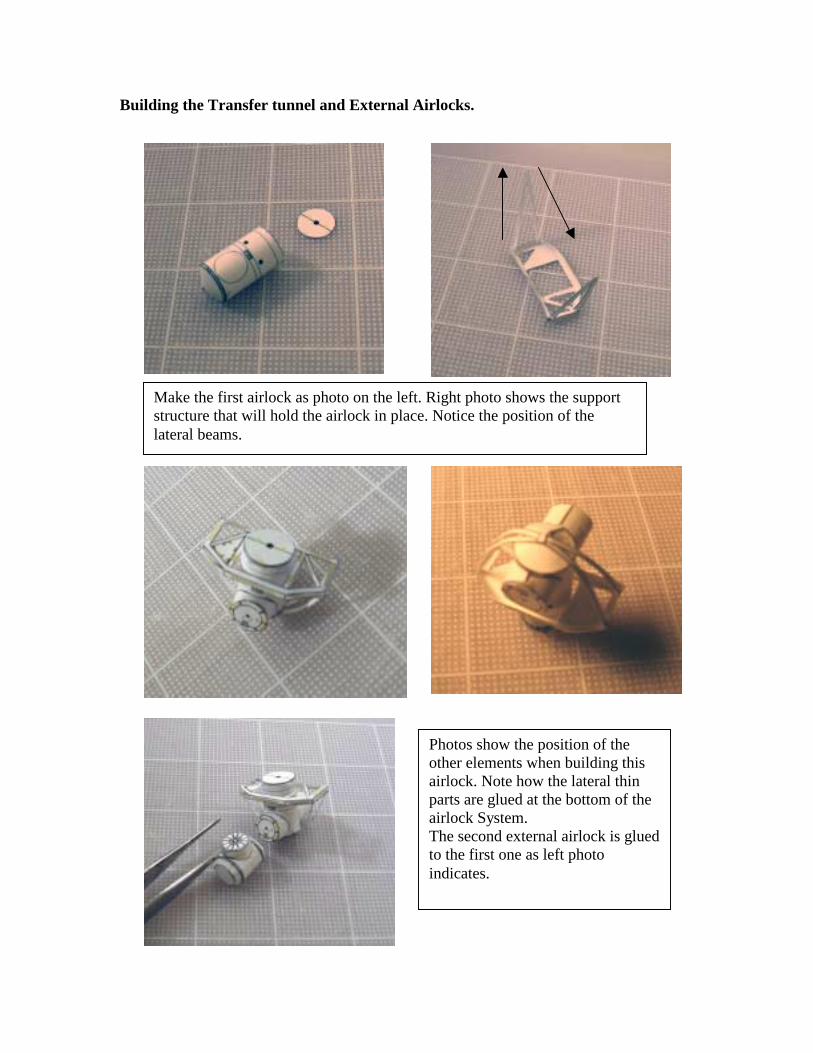
Adding the Spacehab Single Module.
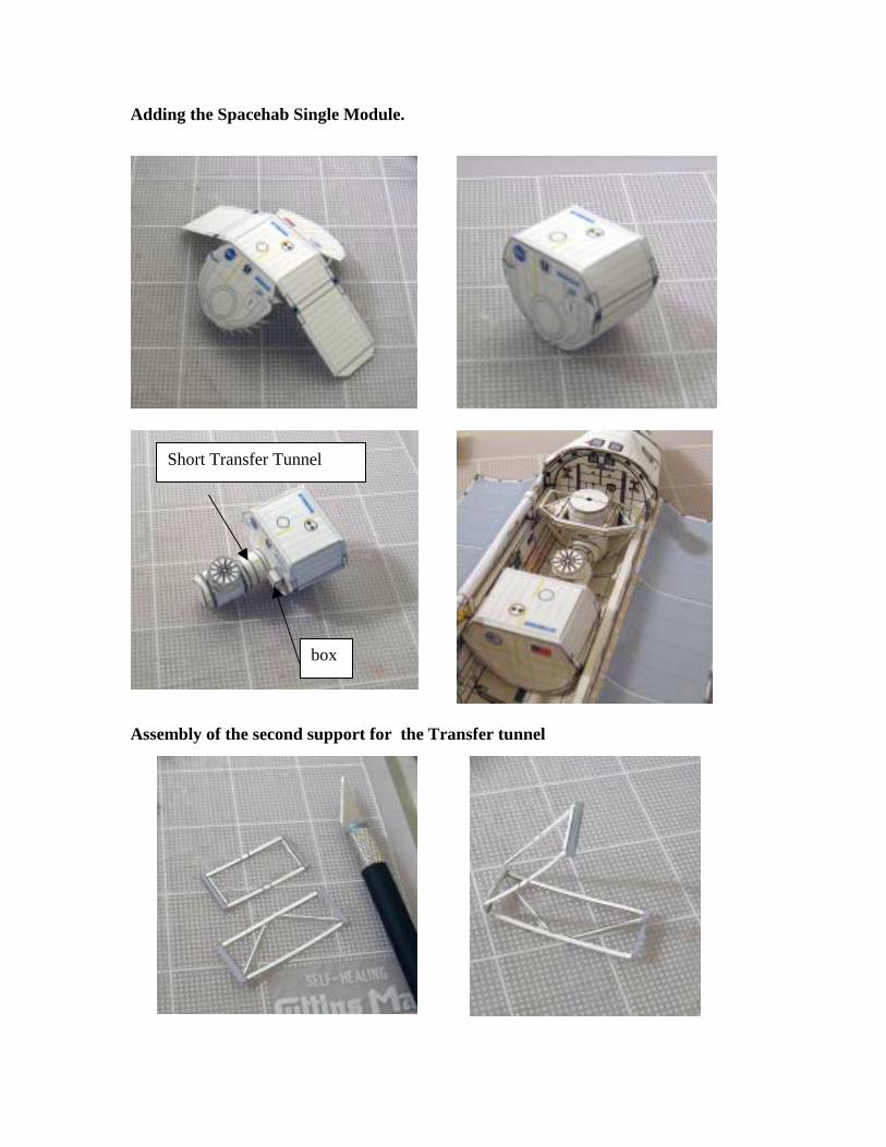
Assembly of the second support for the Transfer tunnel
Short Transfer Tunnel
box

Building the Spartan 201-5 craft
Notice how these parts are put together. Use the craft knife to cut the interior. Use these photos as reference when adding these elements to the payload bay.
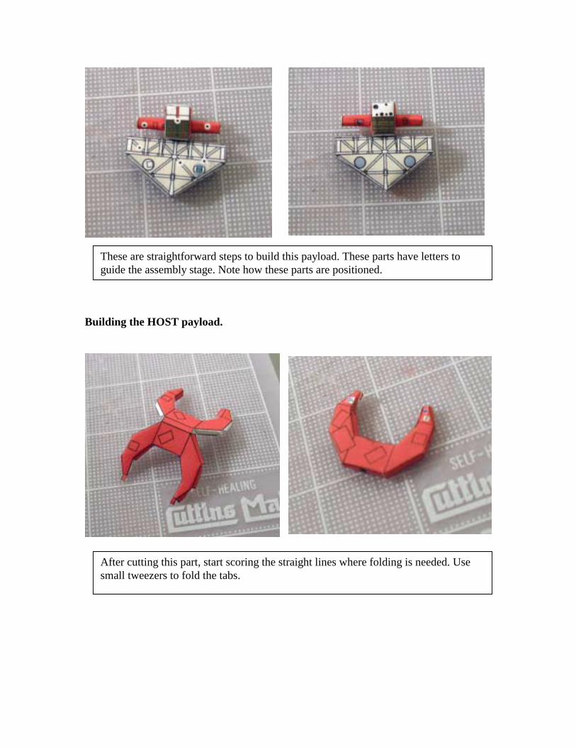
Building the HOST payload.
These are straightforward steps to build this payload. These parts have letters to guide the assembly stage. Note how these parts are positioned.
After cutting this part, start scoring the straight lines where folding is needed. Use small tweezers to fold the tabs.

These 2 parts will become the radiator of the HOST payload. Note how these parts are folded. The left will become a rectangular beam that will be located between the “horns”. The right part folds in the middle and will become the radiator that will be glued to the beam.
Other elements have been glued to the main part. (boxes)

Building the IEH-3 payload.
This payload has many cylinders that are glued on both sides. Follow the letters as indicators where to glue these parts. The small dark cylinder on top of this payload has a “cradle” that will hold it in position. The big box is folded and glued next to the small cylinder.

The IEH-3 view from the front. Note how the elements are positioned.
This is a cylinder that is glued to the back of the IEH-3 payload. Notice how is folded. It has a box attached to the cylinder. First build the cylinder and then make the small box and glue both parts together.

Building the CRYOTSU and Hitchhiker payloads.
The IEH-3 view from the back. Notice the large cylinder with the box.
Note that this payload has 2 elements. A cylinder with an orange “cap” on top and next to it a small box. These elements are glued to the wall of the payload bay. For this photo, both elements have been intentionally glued to a small piece of cardboard in order to “hang” it to the wall for demonstrations purposes only. This same payload bay liner was used for other payload bay model.
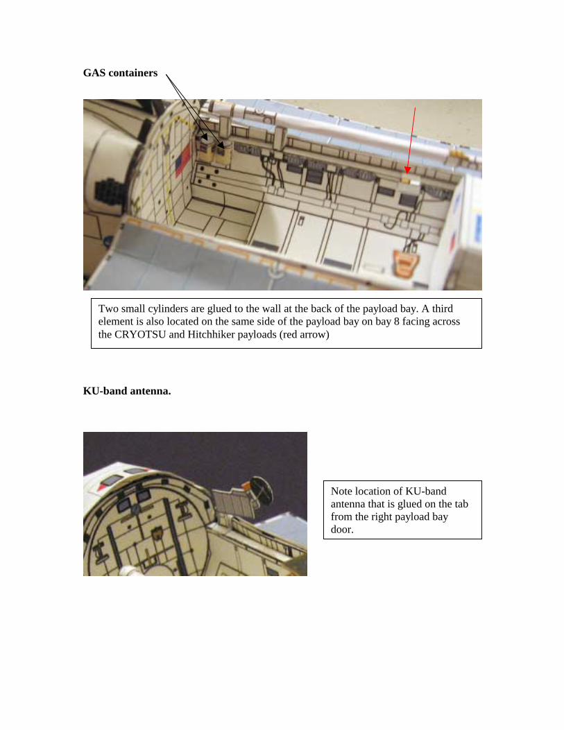
GAS containers
KU-band antenna.
Two small cylinders are glued to the wall at the back of the payload bay. A third element is also located on the same side of the payload bay on bay 8 facing across the CRYOTSU and Hitchhiker payloads (red arrow)
Note location of KU-band antenna that is glued on the tab from the right payload bay door.

Building the Robotic Arm The following photos show a more detailed assembly of the Robotic Arm.
This is one of the support arms that hold in place the Robotic Arm to the side of the payload bay. Note how it is folded.
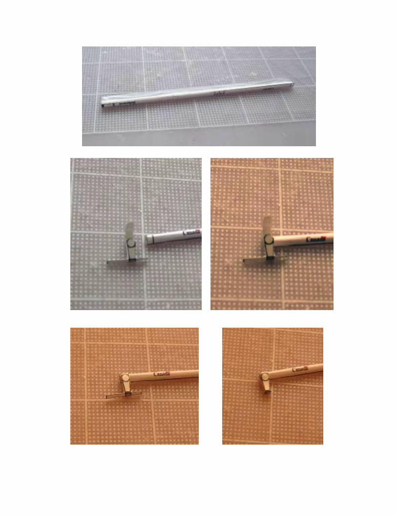

Note how the Robotic Arm camera is built. It is glued to the Robotic Arm next to where the first articulation marker is located. (arrow)
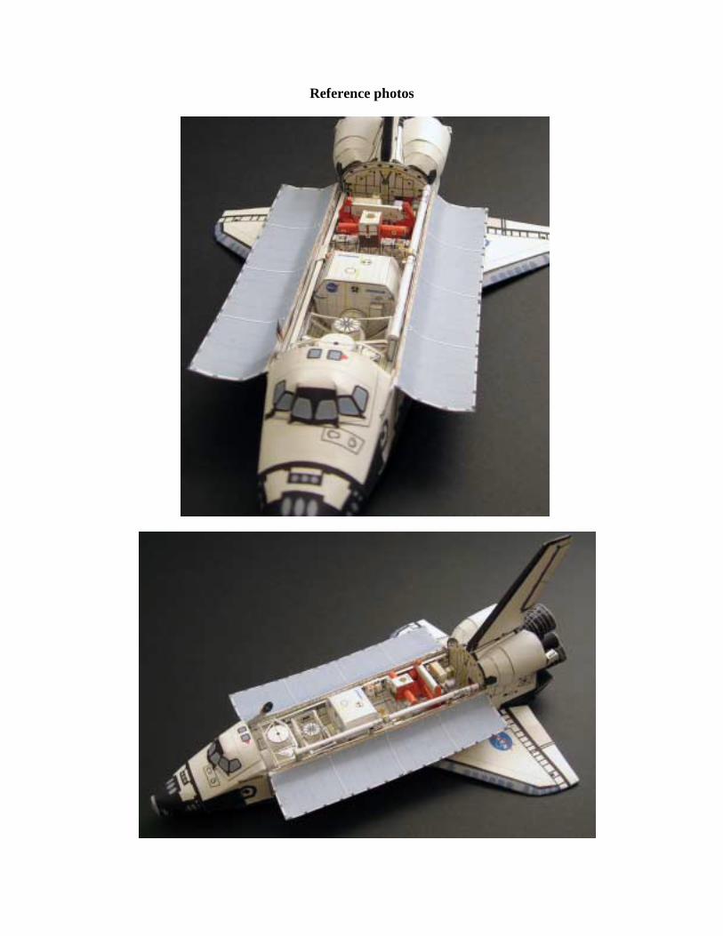
Reference photos

Enjoy this model!
http://www.axmpaperspacescalemodels.com