Assembly Instructions for Large-Scale GMS...
9
1010 B Street, Suite 400 – San Rafael, CA 94901 415-925-9650 – www.sunlink.com Assembly Instructions for Large-Scale GMS Portrait TABLE OF CONTENTS Notices and Safety Precautions Page 1 Installation Tools Page 1 Component Quick Reference Page 2 I - Substrate Installation Guidelines Pages 3-5 II - Panel Assembly Guidelines Page 6 III - Panel Installation Guidelines Page 7 IV - Grounding Recommendations Page 8 Kicker Post Purlin Bracket Clamp Plate Module Purlin Post Frame Kicker Clips
-
Upload
nguyenkhanh -
Category
Documents
-
view
213 -
download
0
Transcript of Assembly Instructions for Large-Scale GMS...

1010 B Street, Suite 400 – San Rafael, CA 94901 415-925-9650 – www.sunlink.com
Assembly Instructions for Large-Scale GMS Portrait
TABLE OF CONTENTS Notices and Safety Precautions Page 1 Installation Tools Page 1 Component Quick Reference Page 2 I - Substrate Installation Guidelines Pages 3-5 II - Panel Assembly Guidelines Page 6 III - Panel Installation Guidelines Page 7 IV - Grounding Recommendations Page 8
Kicker Post
Purlin Bracket
Clamp Plate
Module
Purlin
Post Frame
Kicker Clips

Assembly Instructions for Large-Scale GMS Portrait
Rev 07.08.2015 Page 1
Notices, Safety Precautions, and Installation Tools
Read this document before beginning installation work. Plan for safe practice during any installation activity with respect to hazards from tripping, falling, lifting, repetitive stress, and any overhead or electrical hazards.
This document is not prescriptive regarding safety and does not purport to address all the safety concerns that may arise with its use. Contractors should become familiar with all applicable safety, health and regulatory requirements before beginning work.
Electrical safety notice – Any time a SunLink panel contains two or more electrically interconnected modules, a shock hazard is present. SunLink is a mechanical system and contains no “live” parts. Mechanical installers and electricians should coordinate in order to ensure that all personnel are aware of electrical hazards.
Precedence – The Large-Scale GMS Portrait positions and secures photovoltaic modules. DC “stringing” and interconnection of the modules requires placement of conduit, conduit fittings and combiner boxes.
Field Modifications – Unauthorized field modification of SunLink components or assemblies may affect SunLink warranty coverage. Provide marked up drawings for SunLink’s review, comment and approval prior to attempting any field modifications.
Fasteners – All fasteners required for mechanical completion are furnished with the Large-Scale GMS Portrait. For any assembly, finish initial bolted assembly to finger tight. Refer to the individual steps for detailed information on application. Use of air-powered tools that do not incorporate means to limit applied torque may damage the head of these fasteners and is not recommended
Final inspection – Visually inspect assembled SunLink arrays, roof-mounted or ground supported. The suggested process consists of a row-by-row walk-through and then a perimeter walk-around, after mechanical assembly, before electrical completion. Report any distortion in the assembly or other assembly concerns to SunLink.
GENERAL PROCEDURE NOTES
A. The SunLink Large-Scale GMS Portrait system is installed by following a sequential process detailed in this manual. Please read and follow procedure for best results.
B. At the end of every work day ensure all installed components are securely attached.
INSTALLATION TOOLS Cordless right-angle screwdriver with torque
adjustment and socket adapter Torque wrench 7/8” wrench
9/16” socket 7/8” deep socket Ratchet Impact driver with socket adapter Optional Purlin Bracket assembly jig

Assembly Instructions for Large-Scale GMS Portrait
Rev 07.08.2015 Page 2
Component Quick Reference
ASSEMBLY AIDES
PURLIN BRACKET JIG
COMPONENTS POST
POST FRAME
KICKER
CLAMP PLATE
PURLIN BRACKET
KICKER CLIP
PURLIN

Assembly Instructions for Large-Scale GMS Portrait
Rev 07.08.2015 Page 3
Step 1 - Install posts.
Note: Your project may employ multiple Post sizes, Post lengths, and/or Post embedment depths. A. Refer to construction documents for Post sizes,
recommended Post embedment depths, respective Post locations, and Post installation tolerances.
B. It is recommended that Posts be installed in undisturbed conditions.
C. Please see site-specific geotechnical report for descriptions of site conditions.
Step 2 – Install Clamp Plates. A. Attach one Clamp Plate to each Post as shown. B. Torque fasteners to the specified value. Note: Clamp Plates may be installed on either side of the Post; however consistency should be maintained throughout the site.
Fasteners: • 3 Heavy Hex Bolts, HDG, 1/2”-13 x 1” • 3 Heavy Hex Nuts, HDG, 1/2”-13
Torque: 40-80ft lbs
Assembly Instructions for Large-Scale GMS Portrait
Rev 07.08.2015 Page 4
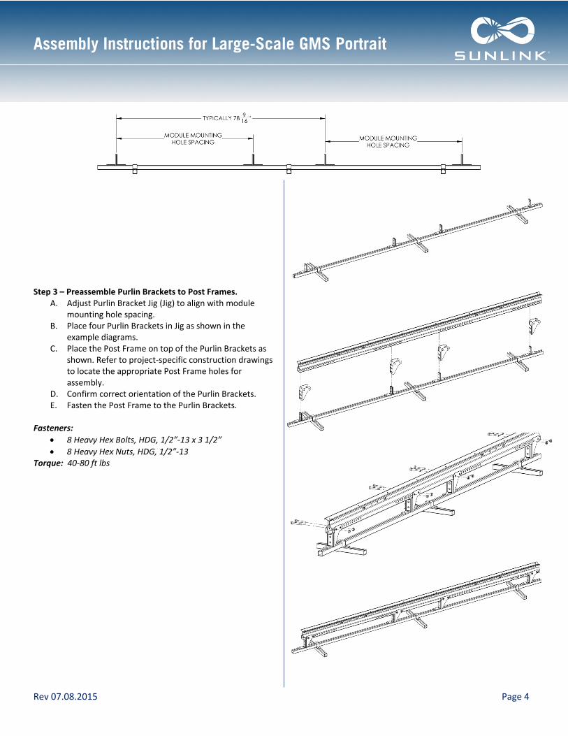
Step 3 – Preassemble Purlin Brackets to Post Frames.
A. Adjust Purlin Bracket Jig (Jig) to align with module mounting hole spacing.
B. Place four Purlin Brackets in Jig as shown in the example diagrams.
C. Place the Post Frame on top of the Purlin Brackets as shown. Refer to project-specific construction drawings to locate the appropriate Post Frame holes for assembly.
D. Confirm correct orientation of the Purlin Brackets. E. Fasten the Post Frame to the Purlin Brackets.
Fasteners: • 8 Heavy Hex Bolts, HDG, 1/2”-13 x 3 1/2” • 8 Heavy Hex Nuts, HDG, 1/2”-13
Torque: 40-80 ft lbs

Assembly Instructions for Large-Scale GMS Portrait
Rev 07.08.2015 Page 5
Step 4 – Install Post Frame. A. Assemble Post Frame to Clamp Plate as shown. B. Ensure Purlin Brackets are oriented in the direction
shown. C. Use vertical slot if necessary to accommodate rolling
terrain or overdriven piles. Fasteners:
• 1 Heavy Hex Bolt, HDG, 1/2”-13 x 1” • 1 Heavy Hex Nut, HDG, 1/2”-13
Torque: 40-80 ft lbs
Step 5 – Fasten Kicker to Post Frame.
A. Assemble Kicker to Post Frame as shown. B. Use the correct Post Frame hole as shown in the
diagram. C. Leave fasteners hand tight until Step 7.
Fasteners:
• 1 Heavy Hex Bolt, HDG, 1/2”-13 x 1” • 1 Heavy Hex Nut, HDG, 1/2”-13
Torque: 40-80 ft lbs
Step 6 – Fasten Kicker to Post. A. Assemble Kicker to Post as shown using two Kicker Clips
per Post. B. Leave fasteners hand tight until Step 7. Note: The appropriate torque value for this connection is dependent upon the size of the Post. The Post flanges will deform slightly as the fastener is tightened. Achieving the correct torque value for this connection is critical. Do not use impact tools to torque this connection.
Fasteners: • 1 Heavy Hex Bolt, HDG, 1/2”-13 x 3 1/2” • 2 Flat Washers, HDG, 1/2” • 1 Heavy Hex Nut, HDG, 1/2”-13 • 1 Split Lock Washer, HDG, 1/2”
Torque: W6x7 – 30±2 ft-lbs; W6x8.5 – 40±2 ft-lbs; W6x9 – 40±2 ft-lbs
Assembly Instructions for Large-Scale GMS Portrait
Rev 07.08.2015 Page 6
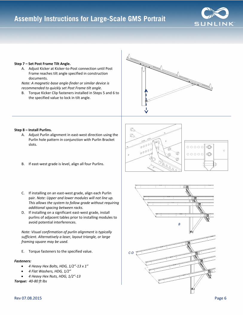
Step 7 – Set Post Frame Tilt Angle.
A. Adjust Kicker at Kicker-to-Post connection until Post Frame reaches tilt angle specified in construction documents.
Note: A magnetic-base angle-finder or similar device is recommended to quickly set Post Frame tilt angle. B. Torque Kicker Clip fasteners installed in Steps 5 and 6 to
the specified value to lock in tilt angle.
Step 8 – Install Purlins.
A. Adjust Purlin alignment in east-west direction using the Purlin hole pattern in conjunction with Purlin Bracket slots.
B. If east-west grade is level, align all four Purlins.
C. If installing on an east-west grade, align each Purlin pair. Note: Upper and lower modules will not line up. This allows the system to follow grade without requiring additional spacing between racks.
D. If installing on a significant east-west grade, install purlins of adjacent tables prior to installing modules to avoid potential interferences.
Note: Visual confirmation of purlin alignment is typically sufficient. Alternatively a laser, layout triangle, or large framing square may be used. E. Torque fasteners to the specified value.
Fasteners:
• 4 Heavy Hex Bolts, HDG, 1/2”-13 x 1” • 4 Flat Washers, HDG, 1/2” • 4 Heavy Hex Nuts, HDG, 1/2”-13
Torque: 40-80 ft lbs
B
C-D

Assembly Instructions for Large-Scale GMS Portrait
Rev 07.08.2015 Page 7
Step 9 – Place first module in each row . A. Determine required orientation of module junction boxes
and place modules. B. Attach each module using four nut/bolt pairs. C. For the best finished aesthetic, space modules evenly as
allowed by the slots on the purlins. Note: The lower two purlins may be left off the rack during assembly of the upper module row to increase accessibility.
Fasteners: • 4 per module:
Serrated Flange Bolt, Stainless, 5/16-18 x 5/8” -OR- Serrated Flange Bolt, Stainless, 1/4”-20 x 5/8”
• 4 per module: Serrated Flange Nut, Stainless, 5/16”-18 -OR- Serrated Flange Nut, Stainless, 1/4”-20
Torque: 10 ±2 ft lbs (5/16”-18) -OR- 6±1 ft lbs (1/4”-20)
Serrated Flange Nut
Lower Row
Upper Row
Flange Bolt

Assembly Instructions for Large-Scale GMS Portrait
Rev 07.08.2015 Page 8
Grounding Recommendations
The Large-Scale GMS Portrait grounding method conforms to UL SUB 2703 and is certified by ETL for use with all photovoltaic modules certified under SunLink’s ETL listing. The benefits of the Large-Scale GMS Portrait grounding method include:
• Reducing grounding lugs from one (1) per PV module to one (1) per continuous Large-Scale GMS Portrait rack. (A continuous Large-Scale GMS Portrait rack is defined as either a single Large-Scale GMS Portrait table or multiple tables bonded together using an appropriate jumper in accordance with all applicable code requirements.)
• Reducing installation time • Reducing overall cost of system
To prevent unnecessary risk of fire, electrical shock or personal injury, all wiring and grounding must be done in accordance with local codes, or in the absence of local codes, with the National Electrical Code, ANSI/NFPA No. 70-Latest Revision (for the US) or the Canadian Electrical Code CSA C22.1 - Latest Revisions and local codes and ordinances.
Bonding the Large-Scale GMS Portrait tables A. Large-Scale GMS Portrait tables may be bonded
together to form a continuous Large-Scale GMS Portrait rack.
B. Use only UL467 listed bonding jumpers. Install jumpers with appropriate hardware per manufacturer specifications and in accordance with all applicable code requirements.
C. Ensure material compatibility with either galvanized steel or anodized aluminum, depending on jumper attachment location.
D. Recommended jumper connection points include purlin to purlin, or module grounding hole to grounding hole. Do not drill additional holes in any Large-Scale GMS Portrait components without written confirmation from SunLink.
Grounding the continuous Large-Scale GMS Portrait rack A. A continuous Large-Scale GMS Portrait Rack may be
grounded by application of a single grounding lug. B. The image to the right shows how a lug can be
applied to the end of a Post Frame. Alternatively, the lug may be applied to other components in the assembly, such as the Purlin. Do not drill additional holes in any Large-Scale GMS Portrait components without written confirmation from SunLink.
C. Use only UL467 listed “direct bury” grounding lugs.
D. Mount and torque grounding lugs with appropriate hardware per manufacturer specifications and in accordance with all applicable code requirements.
Note: Do not connect copper wire directly to steel components.
**NOTE: GROUNDING HARDWARE NOT SUPPLIED BY SUNLINK**
Grounding Lug