Assembly Equipment
24
H1 EATON Synflex Hose and Fittings Master Catalog E-HOOV-MC001-E2 October 2013 HYDRAULIC HOSE GENERAL INFORMATION AIR & WATER HOSE & TUBING TRUCK HOSE AEROQUIP/POLYON FITTINGS AEROQUIP/TTC FITTINGS SYNFLEX FITTINGS WEATHERHEAD (U & Z SERIES) FITTINGS ASSEMBLY EQUIPMENT & INFORMATION TECHNICAL DATA Synflex Swaging Machine, Tools and Accessories ...............................H2-3 Eaton Crimping Machine ....................................................H4-5 Hose Accessories ..........................................................H5-8 O-Rings ................................................................. H9-11 Crimp Die Charts ........................................................H12-15 Selection, Installation, and Maintenance..................................... H16-17 Assembly Instructions .................................................... H18-22 Assembly Equipment
Transcript of Assembly Equipment

H1EATON Synflex Hose and Fittings Master Catalog E-HOOV-MC001-E2 October 2013
HY
DR
AU
LIC
H
OS
EG
EN
ER
AL
INFO
RM
AT
ION
AIR
& W
AT
ER
HO
SE
& T
Ub
ING
TR
UC
K
HO
SE
AE
RO
QU
IP/P
OLY
ON
FIT
TIN
GS
AE
RO
QU
IP/T
TC
FIT
TIN
GS
SY
NFL
EX
FIT
TIN
GS
WE
AT
HE
RH
EA
D
(U &
Z S
ER
IES
)
FITT
ING
S
AS
SE
Mb
LY
EQ
UIP
ME
NT
&
INFO
RM
AT
ION
TE
CH
NIC
AL
DA
TA
Synflex Swaging Machine, Tools and Accessories . . . . . . . . . . . . . . . . . . . . . . . . . . . . . . .H2-3Eaton Crimping Machine . . . . . . . . . . . . . . . . . . . . . . . . . . . . . . . . . . . . . . . . . . . . . . . . . . . .H4-5Hose Accessories . . . . . . . . . . . . . . . . . . . . . . . . . . . . . . . . . . . . . . . . . . . . . . . . . . . . . . . . . .H5-8O-Rings . . . . . . . . . . . . . . . . . . . . . . . . . . . . . . . . . . . . . . . . . . . . . . . . . . . . . . . . . . . . . . . . .H9-11Crimp Die Charts . . . . . . . . . . . . . . . . . . . . . . . . . . . . . . . . . . . . . . . . . . . . . . . . . . . . . . . .H12-15Selection, Installation, and Maintenance. . . . . . . . . . . . . . . . . . . . . . . . . . . . . . . . . . . . .H16-17Assembly Instructions . . . . . . . . . . . . . . . . . . . . . . . . . . . . . . . . . . . . . . . . . . . . . . . . . . . .H18-22
Assembly Equipment

H2 EATON Synflex Hose and Fittings Master Catalog E-HOOV-MC001-E2 October 2013
HY
DR
AU
LIC
HO
SE
GE
NE
RA
L IN
FOR
MA
TIO
NA
IR &
WA
TE
R H
OS
E&
TU
bIN
GT
RU
CK
H
OS
EA
ER
OQ
UIP
/PO
LYO
N
FITT
ING
SA
ER
OQ
UIP
/TT
CFIT
TIN
GS
SY
NFLE
XFIT
TIN
GS
WE
AT
HE
RH
EA
D
(U &
Z S
ER
IES
) FITT
ING
S
AS
SE
Mb
LY
EQ
UIP
ME
NT
&
I NFO
RM
AT
ION
TE
CH
NIC
AL
DA
TA
Synflex Swaging MachinesSST and Mark IX
Designed to Attach Synflex Permanent Fittings to Synflex Hose
• Synflex swagingequipment producessmooth, uniform fittingsurfaces, without raisededges or ridges commonin other fitting methods.
• Complete range offitting swaging pushersand dies up to -16 sizeare ordered separately.
SST Portable Hand SwagerPart No.: 4530-01002
• Portable hand operated machine for field assembly
• Frame can be attached to bench vise or directly toa table with separate mounting bracket
• Weight: 3.6 kgs (8 lbs)
SST Portable Hand Swager Carrying CasePart No.: 45J0-05600
Mark IX SwagerPart No.: 45J0-05600
• Fully automatic - opens dies to release completed assembly
• Fast actuation - capable of five-second cycle time
• Three power supply options for a broad range of productionneeds
• For heavy duty, continuous high-speed production needsthe Mark IX can be equipped with a high capacity power unit(see option three below)
• Weight: 59.4 kgs (131 lbs)
Option 1 (Part No.: 4530-009S0)
1HP, 60Hz,115/208/230V single-phase motor; medium duty
Option 2 (Part No.: 4530-009S1)
1HP, 60 Hz,230/460V three-phase motor; medium duty
Option 3 - A & B (Part No.: 453C-00020 and Part No.: 4530-009S4)
• (A) Mark IX machine without standard power supply.Part No.: 4530-009S4
• (B) Commercial-duty hydraulic power unit with 5HP,three-phase 230/460V motor, five-gallon reservoir,4.1 GPM displacement. Part No.: 453C-00020

H3EATON Synflex Hose and Fittings Master Catalog E-HOOV-MC001-E2 October 2013
HY
DR
AU
LIC
H
OS
EG
EN
ER
AL
INFO
RM
AT
ION
AIR
& W
AT
ER
HO
SE
& T
Ub
ING
TR
UC
K
HO
SE
AE
RO
QU
IP/P
OLY
ON
FIT
TIN
GS
AE
RO
QU
IP/T
TC
FIT
TIN
GS
SY
NFL
EX
FIT
TIN
GS
WE
AT
HE
RH
EA
D
(U &
Z S
ER
IES
)
FITT
ING
S
AS
SE
Mb
LY
EQ
UIP
ME
NT
&
INFO
RM
AT
ION
TE
CH
NIC
AL
DA
TA
Synflex Swaging Machines Tools and Accessories
PushersPusher selection is based on fitting end design chosen from assembly. Pusher part numbers are listed in the fitting tables on pages H12-15.
Example: To attach a -06 (3/8-inch) hose to a -06 female JIC/SAE 37° swivel fitting (90306-065500), use pusher part number 4599-FP015.
DiesSwaging dies are applied in paired sets. Die selection is based on hose series and size. Die part numbers are listed in hose selection chart, page H12-15.
Example: To attach fitting 90306-065500 to a 3130-06 hose, die part number 4540-306 is utilized.
Die and Pusher Storage RackPart No.: 45J0-03401
• Rack holds twelve pushers and eight dies
• 16-gauge welded steel frame
• Wall mount or bench top
• Dimensions: 19 inches wide; 22-1/2 inches high;extends 3 inches from mounting surface

H4 EATON Synflex Hose and Fittings Master Catalog E-HOOV-MC001-E2 October 2013
HY
DR
AU
LIC
HO
SE
GE
NE
RA
L IN
FOR
MA
TIO
NA
IR &
WA
TE
R H
OS
E&
TU
bIN
GT
RU
CK
H
OS
EA
ER
OQ
UIP
/PO
LYO
N
FITT
ING
SA
ER
OQ
UIP
/TT
CFIT
TIN
GS
SY
NFLE
XFIT
TIN
GS
WE
AT
HE
RH
EA
D
(U &
Z S
ER
IES
) FITT
ING
S
AS
SE
Mb
LY
EQ
UIP
ME
NT
&
I NFO
RM
AT
ION
TE
CH
NIC
AL
DA
TA
Crimping MachinesFT 1380 and T-420
The ProCrimp 1380 crimp machine from Eaton crimps all your hose needs up to and including –20 SAE100R12 hose styles and the popular MatchMate Plus hose and fittings program (shown with optional die holder kit FT1380–2–4). The ProCrimp 1380 is electronically controlled to give fast, accurate crimps the first time and every time you need a hose assembly. The electronic keypad is easy to adjust, with up to 10 programmable crimp settings. For hose styles and sizes used less frequently simply enter the 3 digit code of that hose.
Ordering InstructionsSee page H12–15 for tooling information.
FT1380–115 115V crimp machine 50/60 Hz
FT1380–2–3 FT1330 to FT1380 Die Cage conversion kit — back plate, bolts and instructions necessary to convert an FT1330 die cage to an FT1380 die cage. Simply remove the FT1330 back plate and replace it with the new FT1380 back plate.
FT1380–2–4 Optional die holder kit — Kit includes 4 die holder plates each of which will hold 2 die cages. Holes are pre-drilled on base of ProCrimp machine to accept these 4 plates.
FT1380-4 Optional fitting backstop-kit includes backstop and 5/32” hex wrench. The backstop allows the 1380 to crimp PTFE hose and be utilized for a fitting locator to increase efficiency. Ordering Instructions
See page H12–15 for tooling information.
Consult Product Advisor for complete crimp die and proper spacer ring information. Contact Eaton for additional assembly machine options.
Electrical Requirements USA: FT1380–115 standard machine uses 115V, 50/60 Hz, 1.5 hp
Brazil: FT1380–1–2 standard machine uses 230V, 50/60 Hz, 1.5 hp
Australia: FT1380–230 standard machine uses 230V, 50/60 Hz, 1.5 hp
Canada: FT1380–115 standard machine. Requires CSA (Canadian Standards Associ ation) approval. The FT1380–115 is CSA approved and is so noted on the nameplate.
Aeroquip FT1380
The Coll-O-Crimp Super I is a versatile machine ideal for your shop, factory, construction, and mine locations. Big capacity combined with lever-activated crimping gives you wide coverage and a quick and simple way to make factory-quality hose assemblies.
Capacity 3/16" I.D. 1 fiber braid through 1-1/4" 6 spiral hose*; for hose other than 4 and 6 spiral, conversion tooling is required.
*will not crimp 4sp/6sp ends
Mounting Bench or C-40X cabinet.
Size 22" high, 10" wide, 20-1/2" deep
Weight 210 lbs.
CAUTION
The Coll-O-Crimp power source has the pressure relief valve set at 4000 to 4200 PSI. Damage to the press will result if higher pressures are used and warranty will be voided.
Weatherhead T-420
T-420 • Coll-O-Crimp Super I Packages for Z Series-4 thru -16 (no -10), one-wire and two-wire
Package Number ET420-002 ET420-003
Power Source 220V 110VContents Press T-420-1 T-420-1Hose Assembly T-410-22 T-410-22Pump T-421U T-421U-110Adapter Ring T-420-25 T-420-25

H5EATON Synflex Hose and Fittings Master Catalog E-HOOV-MC001-E2 October 2013
HY
DR
AU
LIC
H
OS
EG
EN
ER
AL
INFO
RM
AT
ION
AIR
& W
AT
ER
HO
SE
& T
Ub
ING
TR
UC
K
HO
SE
AE
RO
QU
IP/P
OLY
ON
FIT
TIN
GS
AE
RO
QU
IP/T
TC
FIT
TIN
GS
SY
NFL
EX
FIT
TIN
GS
WE
AT
HE
RH
EA
D
(U &
Z S
ER
IES
)
FITT
ING
S
AS
SE
Mb
LY
EQ
UIP
ME
NT
&
INFO
RM
AT
ION
TE
CH
NIC
AL
DA
TA
Overall Spring Guards
Hose AccessoriesOverall Spring Guards and T-420 Continued
• Abrasion protectionand support
• Protects hose fromkinking
• Order in multiples of7.6 m (25 ft) lengths
Standard Type 2 Type 3 Hose Part Number Length ft Part No. Part No.
3800-03, 3R30-03, 3130-03, 37AL-03 25 4521-50000 -
3800-04, 3R30-04, 3440-04, 3130-04, 25 4521-51000 4521-02000 3V10-03, 37AL-04, 30CT-04
3800-06, 3440-06, 34PW-06, 3130-06, 25 4521-53000 4521-04000 3130-05, 37AL-05, 37AL-06, 30CT-05, 30CT-06
3800-08, 3R30-08, 3440-08, 34PW-08, 25 4521-54000 4521-05000 3130-08, 37AL-08, 30CT-08
34PW-10, 3440-10, 3130-12 25 4521-88000 -
3R80-03 25 4521-83000 -
3V10-04, 3130-05 25 4521-84000 -
3R80-06 25 4521-58000 -
3R80-08 25 4521-59000 4521-10000
3R80-12 25 4521-60000 -
3R80-16 10 4521-61000 -
3R80-04 25 4521-57000 -
T-420-N • Coll-O-Crimp Super I - 220V Package T-420N-110 • Coll-O-Crimp Super I - 110V PackageIncludes one each of the following (with respective pump):
Catalog Number Description
T-420-1 Coll-O-Crimp Super I Press and T-420-M Instructions
T-421U or T-421U-110 220v or 110V Electric PumpT-400-2C ‘U’ Series Collet – 1/4"T-400-3C ‘U’ Series Collet – 3/8" T-400-4C ‘U’ Series Collet – 1/2"T-400-5C ‘U’ Series Collet – 3/4"T-400-6C ‘U’ Series Collet – 1"T-400-10 Spacer Ring – BlackT-400-11 Spacer Ring – SilverT-400-62 Spacer Ring YellowT-410-22 36" Pump to Press Hose AssemblyT-420-25 Adapter Ring for
T-400 Series ColletsT-420-4CN 430 ‘U’ Series Collet – 1/2"T-420-5CN 430 ‘U’ Series Collet –3/4"T-420-6CN 430 ‘U’ Series Collet – 1"
ET420-004 • Coll-O-Crimp I - 220V Package ET420-005 • Coll-O-Crimp I - 110V PackageBoth Packages include the following (with respective pump):
Catalog Number Description
T-420-1 Coll-O-Crimp Super IT-421U or T-421U-110 220v or 110V Electric PumpET400DC-M150S ‘Z’ Series Collet – 1/4”ET400DC-M195S ‘Z’ Series Collet – 3/8”ET400DC-M230S ‘ Z’ Series Collet – 1/2”T-420-85C ‘Z’ Series Collet – 5/8”T-420-86C ‘Z’ Series Collet – 3/4”ET420DC-M380S ‘Z’ Series Collet – 1”T-400-10 Spacer Ring – BlackT-400-62 Spacer Ring –YellowT-420-80R Spacer Ring – Black/WhiteET1000SR-M190D Spacer Ring – Light GreenET420SR-M255A Spacer Ring – Black/GreyET420SR-M495A Spacer Ring – BrownT-410-22 36” Pump to Press Hose AssemblyT-420-25 Adapter Ring for T-400 Series ColletsT-420-4CN 430 ‘U’ Series Collet – 1/2”T-420-5CN 430 ‘U’ Series Collet – 3/4”T-420-6CN 430 ‘U’ Series Collet – 1”T-420-7CN 430 ‘U’ Series Collet – 1-1/4”
H6 EATON Synflex Hose and Fittings Master Catalog E-HOOV-MC001-E2 October 2013
HY
DR
AU
LIC
HO
SE
GE
NE
RA
L IN
FOR
MA
TIO
NA
IR &
WA
TE
R H
OS
E&
TU
bIN
GT
RU
CK
H
OS
EA
ER
OQ
UIP
/PO
LYO
N
FITT
ING
SA
ER
OQ
UIP
/TT
CFIT
TIN
GS
SY
NFLE
XFIT
TIN
GS
WE
AT
HE
RH
EA
D
(U &
Z S
ER
IES
) FITT
ING
S
AS
SE
Mb
LY
EQ
UIP
ME
NT
&
I NFO
RM
AT
ION
TE
CH
NIC
AL
DA
TA
Plastic Protective Coil Sleeve
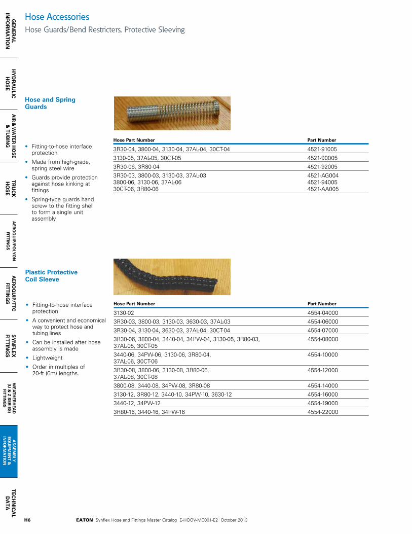
Hose and Spring Guards
Hose Part Number Part Number
3R30-04, 3800-04, 3130-04, 37AL-04, 30CT-04 4521-91005
3130-05, 37AL-05, 30CT-05 4521-90005
3R30-06, 3R80-04 4521-92005
3R30-03, 3800-03, 3130-03, 37AL-03 4521-AG004 3800-06, 3130-06, 37AL-06 4521-94005 30CT-06, 3R80-06 4521-AA005
Hose Part Number Part Number
3130-02 4554-04000
3R30-03, 3800-03, 3130-03, 3630-03, 37AL-03 4554-06000
3R30-04, 3130-04, 3630-03, 37AL-04, 30CT-04 4554-07000
3R30-06, 3800-04, 3440-04, 34PW-04, 3130-05, 3R80-03, 4554-08000 37AL-05, 30CT-05
3440-06, 34PW-06, 3130-06, 3R80-04, 4554-10000 37AL-06, 30CT-06
3R30-08, 3800-06, 3130-08, 3R80-06, 4554-12000 37AL-08, 30CT-08
3800-08, 3440-08, 34PW-08, 3R80-08 4554-14000
3130-12, 3R80-12, 3440-10, 34PW-10, 3630-12 4554-16000
3440-12, 34PW-12 4554-19000
3R80-16, 3440-16, 34PW-16 4554-22000
• Fitting-to-hose interfaceprotection
• Made from high-grade,spring steel wire
• Guards provide protectionagainst hose kinking atfittings
• Spring-type guards handscrew to the fitting shellto form a single unitassembly
• Fitting-to-hose interfaceprotection
• A convenient and economicalway to protect hose andtubing lines
• Can be installed after hoseassembly is made
• Lightweight
• Order in multiples of20-ft (6m) lengths.
Hose AccessoriesHose Guards/Bend Restricters, Protective Sleeving

H7EATON Synflex Hose and Fittings Master Catalog E-HOOV-MC001-E2 October 2013
HY
DR
AU
LIC
H
OS
EG
EN
ER
AL
INFO
RM
AT
ION
AIR
& W
AT
ER
HO
SE
& T
Ub
ING
TR
UC
K
HO
SE
AE
RO
QU
IP/P
OLY
ON
FIT
TIN
GS
AE
RO
QU
IP/T
TC
FIT
TIN
GS
SY
NFL
EX
FIT
TIN
GS
WE
AT
HE
RH
EA
D
(U &
Z S
ER
IES
)
FITT
ING
S
AS
SE
Mb
LY
EQ
UIP
ME
NT
&
INFO
RM
AT
ION
TE
CH
NIC
AL
DA
TA
Molded Black PVC Hose Guards
Vinyl Hose Guards
Hose Part Number Part Number Guard I.D. Guard O.D.
3R30-04, 3440-04, 34PW-04, 3130-04, 4513-04000 9/16 13/16 3R80-03, 37AL-04, 30CT-043R30-06, 3440-06, 34PW-06, 3130-06, 4513-05000 11/16 1-1/16 3R80-04, 37AL-06, 30CT-06 3R80-06 4513-06000 15/16 1-13/143R80-08, 3800-08 4513-10000 15/16 1-5/163130-12, 3R80-12 4513-11000 1-3/16 1-11/16
Guard I.D. Length Hose Part Number Part Number A L
30CT-04, 3R30-04, 3630-04, 3130-04, 3580-04, 45J0-04801 .55 6.0 3R80-03, 3800-04, 37AL-0430CT-06, 3R30-06, 3630-06, 3130-06, 3580-06, 45J0-04802 .69 7.0 3R80-04, 3800-06, 37AL-06
• Assembly abrasionprotection and support
• Use when a non-metallicguard is required. Guardassembly may require theuse of lubricant on thehose
• Available in 15.2m(50-ft) lengths
• Note: 4513-0530m (100-ft) lengths
• Assembly abrasionprotection and support
• Protects against wearwhen a stiffer, non-metalguard is preferred
• Hand-held use,keeps hose fromkinking at fitting
Hose Accessories Hose Guards/Bend Restricters (continued)
ClampsPlastic-covered clamps to secure hose
Hose Part Number Part Number bolt hose Size (in)
3130-02 45J0-00201 13/323130-03, 3630-03, 3800-03, 37AL-03 45J0-00202 13/323130-04, 3630-04, 3800-04, 37AL-04, 30CT-04 45J0-00204 13/323R80-03, 3130-05, 37AL-05, 30CT-05 45J0-00203 13/323R80-04 45J0-00205 13/323130-06, 3630-06, 3800-06, 37AL-06, 30CT-06 45J0-00206 13/323R80-06, 3130-08, 3630-08, 3800-08, 37AL-08, 30CT-08 45J0-00207 13/323R80-08 45J0-00208 13/323130-12 45J0-00209 13/323R80-12, 3630-12 45J0-00210 17/323R80-16 45J0-00212 17/32

H8 EATON Synflex Hose and Fittings Master Catalog E-HOOV-MC001-E2 October 2013
HY
DR
AU
LIC
HO
SE
GE
NE
RA
L IN
FOR
MA
TIO
NA
IR &
WA
TE
R H
OS
E&
TU
bIN
GT
RU
CK
H
OS
EA
ER
OQ
UIP
/PO
LYO
N
FITT
ING
SA
ER
OQ
UIP
/TT
CFIT
TIN
GS
SY
NFLE
XFIT
TIN
GS
WE
AT
HE
RH
EA
D
(U &
Z S
ER
IES
) FITT
ING
S
AS
SE
Mb
LY
EQ
UIP
ME
NT
&
I NFO
RM
AT
ION
TE
CH
NIC
AL
DA
TA
Hand-Held Hose CutterPart No. 4523-04006
• Handy tool for cuttingSynflex hose 1/8-inchto 1/2-inch in diameter.Blades are replaceable.Vinyl cushioned grips.
Replacement Blade
Part No. 4523-04005
Swage LubricantPart No. 4545-01001
• Lubricant for use in theassembly of Synflexreusable and permanentlyattached stainless steelfittings.
Twin-Line Hose Separation ToolPart No. 4574-01000
• Designed for separatingTwin-Line hose
Replacement Blades Part No. 4574-02000 (set of 10)
DiesPart No. 4574-03000-XXX
Hose Assembly Tools & Accessories
Multi-Line Hose Separation ToolPart No. 4573-00000
• Designed for Separationof tri-, quad- and five-linehose.
Replacement BladesPart No. 4573-01000
Vise BlocksPart No. 4504-00000
• 3/16-inch through 1/2-inch hose
Part No. 4504-01000
• 3/4-inch and 1-inch hose.Used in making assemblies.
Insertion Depth MarkerPart No. 45J0-04603
Synflex De-Twinner Die Reference Chart (4574-03000-xxx)
3R30-03 0273R30-04 0033R30-06 0103R30-08 013
3130-02 0013130-03 0023130-04 0043130-05 0083130-06 0113130-08 013
3160-03 0023160-04 0043160-05 0083160-06 0113160-08 013
37AL-03 00237AL-04 00337AL-05 00737AL-06 01037AL-08 01330CT-04 00330CT-05 02230CT-06 01130CT-08 014
3360-03 0023360-04 0043360-05 0233360-06 0243360-08 025
3R80-04 0093R80-06 0123R80-08 0153E80-04 0093E80-06 0123E80-08 015
3V10-03 0053V10-04 0163V10-06 017
3VEO-03 0053VEO-04 0163VEO-06 017
3840-03 0183840-04 0193840-06 0203840-08 021
35NG-03 00435NG-04 02635NG-06 01235NG-08 015
3V20-04 0163V20-06 017
3251-08 006
31DW-04 005
Hose Product Die* No. Hose Product Die* No. Hose Product Die* No. Hose Product Die* No.

H9EATON Synflex Hose and Fittings Master Catalog E-HOOV-MC001-E2 October 2013
HY
DR
AU
LIC
H
OS
EG
EN
ER
AL
INFO
RM
AT
ION
AIR
& W
AT
ER
HO
SE
& T
Ub
ING
TR
UC
K
HO
SE
AE
RO
QU
IP/P
OLY
ON
FIT
TIN
GS
AE
RO
QU
IP/T
TC
FIT
TIN
GS
SY
NFL
EX
FIT
TIN
GS
WE
AT
HE
RH
EA
D
(U &
Z S
ER
IES
)
FITT
ING
S
AS
SE
Mb
LY
EQ
UIP
ME
NT
&
INFO
RM
AT
ION
TE
CH
NIC
AL
DA
TA
Hose Accessories Aeroquip O-Rings
O-Rings Seal Kit
FF16087-01
Includes metal box, o-rings for ORS -04 through -16, o-rings boss -04 through -16,24 packages with twelve 90 durometer nitrile o-rings per package. Packages can be ordered individually by part number listed.
Bonded Seal
Part Number
BSPP Thread
Size
A RefInch
C RefInch
ERefInch
FF9895-02 1/8 - 28 0.625 0.403 0.080
FF9895-04 1/4 - 19 0.810 0.536 0.080
FF9895-06 3/8 - 19 0.937 0.675 0.080
FF9895-08 1/2 - 14 1.125 0.843 0.097
FF9895-10 5/8 - 14 1.250 0.920 0.097
FF9895-12 3/4 - 14 1.375 1.060 0.097
FF9895-16 1-11 1.685 1.329 0.133
FF9895-24 1 1/2 - 11 2.307 1.902 0.133
FF9895-32 2-11 2.875 2.380 0.133
BSPP Bonded Sealfor DIN 3852-2 Ports
A C
E
Connection Size
12 O-ringPackagePart No.
Individual O-Ring Part No.
ORS* –04 FF10266–01–11 FF9446–11
ORS* –06 FF10266–01–12 FF9446–12
ORS* –08 FF10266–01–14 FF9446–14
ORS* –10 FF10266–01–16 FF9446–16
ORS* –12 FF10266–01–18 FF9446–18
ORS* –16 FF10266–01–21 FF9446–21
O-Ring Boss –04 FF10273–01–04 22617–4
O-Ring Boss –05 FF10273–01–05 22617–5
O-Ring Boss –06 FF10273–01–06 22617–6
O-Ring Boss –08 FF10273–01–08 22617–8
O-Ring Boss –10 FF10273–01–10 22617–10
O-Ring Boss –12 FF10273–01–12 22617–12
O-Ring Boss –16 FF10273–01–16 22617–16
O-Ring Boss –32 FF10273–01–32 22617–32
Split Flange –32 FF10266–01–228 FF9446–228
*For ORS o-ring kit order part number: FF10265-01, onlyincludes ORS o-rings.
Material: Steel with bonded Nitrile (Buna-N) seal.

H10 EATON Synflex Hose and Fittings Master Catalog E-HOOV-MC001-E2 October 2013
HY
DR
AU
LIC
HO
SE
GE
NE
RA
L IN
FOR
MA
TIO
NA
IR &
WA
TE
R H
OS
E&
TU
bIN
GT
RU
CK
H
OS
EA
ER
OQ
UIP
/PO
LYO
N
FITT
ING
SA
ER
OQ
UIP
/TT
CFIT
TIN
GS
SY
NFLE
XFIT
TIN
GS
WE
AT
HE
RH
EA
D
(U &
Z S
ER
IES
) FITT
ING
S
AS
SE
Mb
LY
EQ
UIP
ME
NT
&
I NFO
RM
AT
ION
TE
CH
NIC
AL
DA
TA
Hose Accessories Aeroquip O-Rings (continued)
O-RingBaseNo. Material
Operating Temperature
Range
22617(Standard)
90 DurometerBuna–N
Nitrile Rubber
–34°C to +121°C(–30°F to +250°F)
22033 EPREthylene Propylene
Rubber
–55°C to +100°C(–65°F to +212°F)
22068 Viton*Fluoroelastomer
–25°C to +205°C(–15°F to +400°F)
22012 Buna–N, LowTemperatureNitrile Rubber
–55°C to +107°C(–65°F to +225°F)
Designating Separate SAE Boss O-RingsTo order Eaton o-rings separately without fittings specify the size and material by using the o-ring base number and dash size. The charts below offer a simple method to assure the correct o-ring for your application.
O-Ring Dash Size
Tube Size A E
mm in mm in
–4 –04 (1/4) 8,9 0.351 1,8 0.072
–6 –06 (3/8) 11,9 0.468 2,0 0.078
–8 –08 (1/2) 16,3 0.644 2,3 0.087
–10 –10 (5/8) 19,3 0.755 2,5 0.097
–12 –12 (3/4) 23,4 0.924 3,0 0.116
–16 –16 (1) 29,7 1.171 3,0 0.116
Designating Separate ORS O-Rings for AeroquipTo order Eaton o-rings separately without fittings specify the size and material by using the o-ring designator and o-ring base number. The charts to the right offer a simple method to assure the correct o-ring for your application.
O-RingBaseNo. Material
Operating Temperature
Range
22617(Standard)
90 DurometerBuna–N
Nitrile Rubber
–34°C to +121°C(–30°F to +250°F)
22033 EPREthylene Propylene
Rubber
–55°C to +100°C(–65°F to +212°F)
22068 Viton*Fluoroelastomer
–25°C to +205°C(–15°F to +400°F)
22012 Buna–N, LowTemperatureNitrile Rubber
–55°C to +107°C(–65°F to +225°F)
O-Ring Size
Designation
ORSTube Size A E
mm in mm in
–11 –04 7,6 0.301 1,8 0.07
–12 –06 9,2 0.364 1,8 0.07
–14 –08 12,4 0.489 1,8 0.07
–16 –10 15,6 0.614 1,8 0.07
–18 –12 18,8 0.739 1,8 0.07
–21 –16 23,5 0.926 1,8 0.07

H11EATON Synflex Hose and Fittings Master Catalog E-HOOV-MC001-E2 October 2013
HY
DR
AU
LIC
H
OS
EG
EN
ER
AL
INFO
RM
AT
ION
AIR
& W
AT
ER
HO
SE
& T
Ub
ING
TR
UC
K
HO
SE
AE
RO
QU
IP/P
OLY
ON
FIT
TIN
GS
AE
RO
QU
IP/T
TC
FIT
TIN
GS
SY
NFL
EX
FIT
TIN
GS
WE
AT
HE
RH
EA
D
(U &
Z S
ER
IES
)
FITT
ING
S
AS
SE
Mb
LY
EQ
UIP
ME
NT
&
INFO
RM
AT
ION
TE
CH
NIC
AL
DA
TA
Hose Accessories Weatherhead O-Rings
O-ring, FOR-SEAL® Fittings Material:
Buna N, 90 Durometer
Temperature Range: -40°C to +121°C (-40°F to +250°F)
Standard o-ring complies with SAE specification SAE J515 Type CH
Tube Part O.D. Number W I.D.
1/4 4629x4 .070 ± .005 .301 ± .005
3/8 4629x6 .070 ± .005 .364 ± .005
1/2 4629x8 .070 ± .005 .489 ± .005
5/8 4629x10 .070 ± .005 .614 ± .005
3/4 4629x12 .070 ± .005 .739 ± .005
1 4629x16 .070 ± .006 .926 ± .006
Straight Thread O-ring
W
I.D.
Material:
Buna N, 90 Duromete
Temperature Range: -40°C to +121°C (-40°F to +250°F)
Standard O-ring complies with SAE specification SAE J515 Type CH
Port Part Size Number W I.D.
1/16 7629x1 .058 .185
1/8 7629x2 .064 .239
3/16 7629x3 .064 .301
1/4 7629x4 .072 .351
5/16 7629x5 .072 .414
3/8 7629x6 .078 .468
7/16 7629x7 .082 .530
1/2 7629x8 .087 .644
5/8 7629x10 .097 .755
3/4 7629x12 .116 .924
7/8 7629x14 .116 1.048
1 7629x16 .116 1.171

H12 EATON Synflex Hose and Fittings Master Catalog E-HOOV-MC001-E2 October 2013
HY
DR
AU
LIC
HO
SE
GE
NE
RA
L IN
FOR
MA
TIO
NA
IR &
WA
TE
R H
OS
E&
TU
bIN
GT
RU
CK
H
OS
EA
ER
OQ
UIP
/PO
LYO
N
FITT
ING
SA
ER
OQ
UIP
/TT
CFIT
TIN
GS
SY
NFLE
XFIT
TIN
GS
WE
AT
HE
RH
EA
D
(U &
Z S
ER
IES
) FITT
ING
S
AS
SE
Mb
LY
EQ
UIP
ME
NT
&
I NFO
RM
AT
ION
TE
CH
NIC
AL
DA
TA
Crimp Die Chart Aeroquip and Synflex
Old Hose P/N Old Fitting Old Tooling New Hose P/N Qualified FittingRecommended
Tooling
100R
7
FC372-02
PolyonFitting
-M090 3130-02 Polyon / FC5810 -M090
FC372-03 -M1203130-03 Polyon / FC5810 -M120
3130-03 903 Series -M120
FC372-04 -M120
3130-04 Polyon / FC5810 -M120
3130-04 903 Series -M120
3130-04 Global TTC -M150
FC372-05 -M1503130-05 Polyon / FC5810 -M150
3130-05 903 Series -M150
FC372-06 -M180
3130-06 Polyon / FC5810 -M180
3130-06 903 Series -M150
3130-06 Global TTC -M195
FC372-08 M210
3130-08 Polyon / FC5810 -M210
3130-08 903 Series -M210
3130-08 Global TTC -M240
FC372-12 -M280
3130-12 Polyon / FC5810 -M280
3130-12 903 Series -M240
3130-12 Global TTC -M295
FC372-16 -M3203130-16 Polyon / FC5810 -M320
3130-16 Global TTC -M390
FC373-02 -M090 FC373-02 Polyon -M090
FC373-03 -M12037AL-03 Polyon / FC5810 -M120
37AL-03 903 Series -M120
FC373-04 -M12037AL-04 Polyon / FC5810 -M120
37AL-04 903 Series -M120
FC373-05-M150 37AL-05 Polyon / FC5810 -M150
37AL-05 903 Series -M150
FC373-06 -M18037AL-06 Polyon / FC5810 -M180
37AL-06 903 Series -M150

H13EATON Synflex Hose and Fittings Master Catalog E-HOOV-MC001-E2 October 2013
HY
DR
AU
LIC
H
OS
EG
EN
ER
AL
INFO
RM
AT
ION
AIR
& W
AT
ER
HO
SE
& T
Ub
ING
TR
UC
K
HO
SE
AE
RO
QU
IP/P
OLY
ON
FIT
TIN
GS
AE
RO
QU
IP/T
TC
FIT
TIN
GS
SY
NFL
EX
FIT
TIN
GS
WE
AT
HE
RH
EA
D
(U &
Z S
ER
IES
)
FITT
ING
S
AS
SE
Mb
LY
EQ
UIP
ME
NT
&
INFO
RM
AT
ION
TE
CH
NIC
AL
DA
TA
Crimp Die Chart Aeroquip and Synflex (continued)
Old Hose P/N Old Fitting Old Tooling New Hose P/N Qualified FittingRecommended
Tooling10
0R7
FC373-08
Polyon Fitting
-M21037AL-08 Polyon / FC5810 -M210
37AL-08 903 Series -M210
FC373-12 -M280
3740-12 Polyon / FC5810 -M280
3740-12 903 Series -M240
3740-12 Global TTC -M320
FC373-16 -M3203740-16 Polyon / FC5810 -M320
3740-16 Global TTC -M370
100R
8
FC374-03
Polyon Fitting
-M1203R80-03 90H Series -M120
3800-03 903 Series -M120
FC374-04 -M1203R80-04 90H Series -M150
3800-04 903 Series -M120
FC374-06 -M180
3R80-06 90H Series -M180
3R80-06 Global TTC -M180
3800-06 903 Series -M150
FC374-08 -M210
3R80-08 90H Series -M210
3R80-08 Global TTC -M240
3800-08 903 Series -M210
FC374-12 -M280
3R80-12 90H Series -M280
3R80-12 Global TTC -M320
3R80-16 Global TTC -M370
FC375-03 -M120 3E80-03 90H Series -M120
FC375-04 -M120 3E80-04 90H Series -M150
FC375-06 -M1803E80-06 90H Series -M180
3E80-06 Global TTC -M180
FC375-08 -M2103E80-08 90H Series -M210
3E80-08 Global TTC -M240
FC375-12 -M2803E80-12 90H Series -M280
3E80-12 Global TTC -M320
3E80-16 Global TTC -M370

H14 EATON Synflex Hose and Fittings Master Catalog E-HOOV-MC001-E2 October 2013
HY
DR
AU
LIC
HO
SE
GE
NE
RA
L IN
FOR
MA
TIO
NA
IR &
WA
TE
R H
OS
E&
TU
bIN
GT
RU
CK
H
OS
EA
ER
OQ
UIP
/PO
LYO
N
FITT
ING
SA
ER
OQ
UIP
/TT
CFIT
TIN
GS
SY
NFLE
XFIT
TIN
GS
WE
AT
HE
RH
EA
D
(U &
Z S
ER
IES
) FITT
ING
S
AS
SE
Mb
LY
EQ
UIP
ME
NT
&
I NFO
RM
AT
ION
TE
CH
NIC
AL
DA
TA
Crimp Die Chart Weatherhead and Synflex
Old Hose P/N
Old Fitting
Old Fitting Tooling
Old Fitting Spacer Ring
New Hose P/N
Qualified Fitting
New Tooling* Spacer Ring*
100R
7
H43603
“E”Series
T-400-113C Black 3130-03 903 Series M095S Lt Green FSU
H43604 T-400-31C Black
3130-04 U Series T-400-2C Purple FSU
3130-04 903 Series T-400-2C Black FSD
3130-04 Z Series w/ Sleeve T-400-121C Yellow FSU
H43605 T-400-32C Black3130-05 903 Series M150S Black FSD
3130-05 903 Series M150S Black FSD
H43606 T-400-33C Black
3130-06 U Series T-400-3C Red FSU
3130-06 903 Series M150S Lt Green FSU
3130-06 Z Series w/ Sleeve T-400-110C Yellow FSU
H43608 T-400-34C Black
3130-08 U Series T-400-4C Purple FSU
3130-08 903 Series T-400-123C Purple FSU
3130-08 Z Series w/ Sleeve T-400-42C Black/Tan FSU
H43612 T-400-35C Black
3130-12 U Series T-400-5C Red FSU
3130-12 903 Series T-420-185C Brown FSU
3130-12 Z Series w/ Sleeve M295S Yellow FSU
H43616 T-400-36C Black 3130-16 Z Series w/ Sleeve M390S Black/Magenta
FSU
H43503 T-400-113C Black 37AL-03 903 Series M095S Lt Green FSU
H43504 T-400-31C Black 37AL-04 903 Series T-400-2C Tan
H43505 T-400-32C Black 37AL-05 903 Series M150S Black/Tan FSD
H43506 T-400-33C Black37AL-06 U Series T-400-3C Red FSU
37AL-06 903 Series M150S Lt Green FSU
H43508 T-400-34C Black37AL-08 U Series T-400-4C Green FSU
37AL-08 903 Series T-400-123C Purple FSU
H43512 T-400-35C Black
3740-12 U Series T-400-5C Green FSU
3740-12 903 Series T-440-85C Brown FSU
3740-12 Z Series w/ Sleeve M295S Yellow FSU
H43516 T-400-36C Black3740-16 U-Series T-400-6C Red FSU
3740-16 Z Series w/ Sleeve M390S Black/Magenta
FSU
*Consult Product Advisor for complete crimp die and proper spacer ring information.

H15EATON Synflex Hose and Fittings Master Catalog E-HOOV-MC001-E2 October 2013
HY
DR
AU
LIC
H
OS
EG
EN
ER
AL
INFO
RM
AT
ION
AIR
& W
AT
ER
HO
SE
& T
Ub
ING
TR
UC
K
HO
SE
AE
RO
QU
IP/P
OLY
ON
FIT
TIN
GS
AE
RO
QU
IP/T
TC
FIT
TIN
GS
SY
NFL
EX
FIT
TIN
GS
WE
AT
HE
RH
EA
D
(U &
Z S
ER
IES
)
FITT
ING
S
AS
SE
Mb
LY
EQ
UIP
ME
NT
&
INFO
RM
AT
ION
TE
CH
NIC
AL
DA
TA
Crimp Die Chart Weatherhead and Synflex (continued)
Old Hose P/N
Old Fitting
Old Fitting Tooling
Old Fitting Spacer Ring
New Hose P/N
Qualified Fitting
New Tooling* Spacer Ring*
100R
8
H33603
336E Fitting
T-400-120C Black3R80-03 336E / 90H
Series T-400-2C Green
3R80-03 903 Series M095S Lt. Green
H33604 T-400-121C Black3R80-04 336E / 90H
Series M150S Yellow
3800-04 903 Series T-400-121C Magenta
H33606 T-400-122C Black
3R80-06 336E / 90H Series M195S Purple
3R80-06 Z Series w/ Sleeve M195S Tan
3R80-06 903 Series M150S Black
H33608 T-400-123C Black
3R80-08 336E / 90H Series T-400-123C Black
3R80-08 Z Series w/ Sleeve T-400-42C Black/Tan
3800-08 903 Series T-400-41C Yellow
H33612 T-420-15C N/A3R80-12 336E / 90H
Series T-440-85C Black/Orange
3R80-12 Z Series w/ Sleeve T-440-86C Black/Magenta
H33616 T-420-16C N/A 3R80-16 Z Series w/ Sleeve M380S Black/Magenta
H335-03 T-400-120C Black 3E80-03 336E / 90H Series T-400-2C Green
H335-04 T-400-121C Black 3E80-04 336E / 90H Series M150S Yellow
H335-06 T-400-122C Black 3E80-06 336E / 90H
Series M195S Purple
3E80-06 Z Series w/ Sleeve M195S Tan
H335-08 T-400-123C Black 3E80-08 336E / 90H
Series T-400-123C Black
3E80-08 Z Series w/ Sleeve T-400-42C Black/Tan
H335-12 T-420-15C X3E80-12 336E / 90H
Series T-440-85C Black/Orange
3E80-12 Z Series w/ Sleeve T-440-86C Black/Magenta
H335-16 T-420-16C X 3E80-16 Z Series w/ Sleeve M380S Black/Magenta
*Consult Product Advisor for complete crimp die and proper spacer ring information.

H16 EATON Synflex Hose and Fittings Master Catalog E-HOOV-MC001-E2 October 2013
HY
DR
AU
LIC
HO
SE
GE
NE
RA
L IN
FOR
MA
TIO
NA
IR &
WA
TE
R H
OS
E&
TU
bIN
GT
RU
CK
H
OS
EA
ER
OQ
UIP
/PO
LYO
N
FITT
ING
SA
ER
OQ
UIP
/TT
CFIT
TIN
GS
SY
NFLE
XFIT
TIN
GS
WE
AT
HE
RH
EA
D
(U &
Z S
ER
IES
) FITT
ING
S
AS
SE
Mb
LY
EQ
UIP
ME
NT
&
I NFO
RM
AT
ION
TE
CH
NIC
AL
DA
TA
Selection, Installation and Maintenance of Synflex Hose and Assemblies
Proper hose selection, installation and maintenance practices should be followed to ensure that hose and hose assemblies have long life and operate safely. Failure to consider these practices could result in unplanned down-time, damage or injury. The general industry practices assembled below are provided as a guide for hose selection, installation and maintenance. Careful consideration for applying these practices is recommended.
PressureDetermine the maximum operating system pressure and select a hose that will have a maximum working pressure equal to or in excess of the operation system’s maximum pressure. It is very important to take into account surge pressures that may be higher than normal operating pressures.
TemperatureDetermine the maximum and minimum operating temperatures and select a hose that is designed for use within this temperature range. Consider transient thermal conditions resulting from startup, heat build up from idling, etc. Special protection from hot equipment may be required.
Chemical and Environmental Resistance Determine the type and concentration of the fluids and chemicals that will come in contact with the hose core tube I.D. and hose cover. Refer to the hose and tubing sections with product descriptions to identify the types of polymers used to form the core tube and cover. With this information, locate the compatibility rating of the combination of chemicals and/or fluids with the polymer type described in the Chemical Resistance data on pages I12-13. Contact Eaton technical support to request data for chemicals and conditions not listed.
SizeSelect the proper I.D. based on system requirements such as fluid flow rate or velocity. The hose selection nomograph on page I4 can help determine the hose I.D.
Electrical ConductivityEach hose application should be evaluated for the importance of selecting a hose designed to prevent flow of electrical current (e.g. aerial hydraulics) or a hose designed to sufficiently conduct static electricity to safe ground connections. The conducting hose design requires special conducting fittings which should be selected along with the hose.
Component Inspection
Prior to installation, inspect hose for I.D. obstruction or damage such as blisters, looseness or cracks in the hose cover and evidence of having been kinked. Check fittings for thread damage or bent fitting components.
RoutingMany problems can be avoided by installing hose and hose assemblies away from hot equipment such as exhaust manifolds. Insulating heat shields may be necessary in some cases (Figure 1).
figure 1bCorrect
Incorrect figure 1a

H17EATON Synflex Hose and Fittings Master Catalog E-HOOV-MC001-E2 October 2013
HY
DR
AU
LIC
H
OS
EG
EN
ER
AL
INFO
RM
AT
ION
AIR
& W
AT
ER
HO
SE
& T
Ub
ING
TR
UC
K
HO
SE
AE
RO
QU
IP/P
OLY
ON
FIT
TIN
GS
AE
RO
QU
IP/T
TC
FIT
TIN
GS
SY
NFL
EX
FIT
TIN
GS
WE
AT
HE
RH
EA
D
(U &
Z S
ER
IES
)
FITT
ING
S
AS
SE
Mb
LY
EQ
UIP
ME
NT
&
INFO
RM
AT
ION
TE
CH
NIC
AL
DA
TA
Minimum Bend RadiusTight bends (Figure 2) that exceed the hose minimum bend radius should be avoided. Spring guards or stress relief sleeves may be required to protect against exceeding prescribed minimum bend radii.
Torsional FlexingWhen equipment parts exhibit relative motion, hose connections should be located so hoses bend instead of twist.
Fitting ConnectionsFollow the fitting installation instructions provided in this catalog or enclosed with assembly equipment and described in product standards. Attach only the fittings specified for each hose design and do not mix components that are produced by different manufacturers. Proper fitting end selection is very important to eliminate twists and kinks in installed assemblies when connecting fittings to port connections. Swivel fittings are designed to allow for the hex rotation during tightening and bent tube or elbow fittings can eliminate kinks (Figure 3).
Torque Wrench ApplicationUse torque values where specified when tightening fitting connections to prevent leakage and damage.
Final Check OutAfter components are assembled, purge entrapped air and pressurize system to maximum operating pressure. Inspect for leaks and proper function. Perform electrical conductivity tests on designs serving as static electricity discharge paths.
It is important that designers and users consider hose and hose assemblies as having a finite life. Therefore maintenance and replacement is usually necessary at specific intervals.
Maintenance IntervalFrequency of maintenance inspection should be determined by the system designer as well as user feedback based on the severity of the application, including service life data and risk potential.
Maintenance ProgramRecommended maintenance should include the following steps as minimum practice:
LeakageTurn off equipment and bleed down pressures prior to inspection to minimize risk to personnel. Inspect the full length of the hose and fitting connections for leaks.
DamageInspect hose for cuts, abrasion, cracks, blisters, kinked or crushed areas, heat degradation or cover looseness at the port or hose connection. Inspect hose guards for damage.
Electrical ContinuityIn applications requiring the hose assembly to conduct static electricity to a ground connection, test hose assemblies using a megohmeter in accordance with recommended procedures described on the permanently attached tag.
ReplacementHose and/or assembly replacement should be considered at specific intervals under normal conditions. If leakage, loss of conductivity (when required), fitting separation and/or signs of damage are detected, the hose assembly should be replaced immediately.
Hose RoutingUnder pressure, a hose may change in length. Always provide some slack in the hose to allow for this shortening or elongation. However, excessive slack in hose lines may cause poor appearance (Figure 4).
Incorrect
Correct
figure 2
Incorrect
Correct
figure 3
Incorrect
Correct
figure 4
Selection, Installation and Maintenance of Synflex Hose and Assemblies

H18 EATON Synflex Hose and Fittings Master Catalog E-HOOV-MC001-E2 October 2013
HY
DR
AU
LIC
HO
SE
GE
NE
RA
L IN
FOR
MA
TIO
NA
IR &
WA
TE
R H
OS
E&
TU
bIN
GT
RU
CK
H
OS
EA
ER
OQ
UIP
/PO
LYO
N
FITT
ING
SA
ER
OQ
UIP
/TT
CFIT
TIN
GS
SY
NFLE
XFIT
TIN
GS
WE
AT
HE
RH
EA
D
(U &
Z S
ER
IES
) FITT
ING
S
AS
SE
Mb
LY
EQ
UIP
ME
NT
&
I NFO
RM
AT
ION
TE
CH
NIC
AL
DA
TA
How to Assemble Permanent Hose FittingsSynflex Mark IX Swaging Machine
1. Cut hose squarely with hand-held hose cutter 4523-04006or bench-mounted hosecutter 4523-04007.
2. Mark hose for properinsertion depth intofitting. Use insertion depthchart or use insertion depthmarker 45J0-04603.
3. Oil inside hose diameter withSAE 20 oil.
Consult Eaton’s Technical Support for oxygensystem special assemblyrecommendations.
4. Insert hose into fitting todepth mark. (Use vise block4504-00000 or 4504-01000and rubber mallet to easeassembly.)
5. Insert the specified die andpusher into the swagingmachine.
6. Lubricate die swagingsurface with SAE 90 gearoil. For stainless steelfittings use swagelubricant 4545-01001.
7. Insert hose end into thepusher.
8. Pull control lever and guidefitting into the die until thepusher bottom is against thetop of the die surface.
9. Push control lever to retractpusher and open die halves.Remove swaged hoseassembly.
Fitting Series Insertion Depth (in)
903, Hose I.D. 90H, 90L 906 (in) 90A, 90N1/8 9/16 -3/16 25/32 -1/4 1-1/16 7/85/16 1-1/8 -3/8 1-1/4 1-1/41/2 1-1/2 1-1/25/8 1-9/16 -3/4 1-11/16 -1 2-1/16 -
Permanent Fitting Chart Insertion Depth Table

H19EATON Synflex Hose and Fittings Master Catalog E-HOOV-MC001-E2 October 2013
HY
DR
AU
LIC
H
OS
EG
EN
ER
AL
INFO
RM
AT
ION
AIR
& W
AT
ER
HO
SE
& T
Ub
ING
TR
UC
K
HO
SE
AE
RO
QU
IP/P
OLY
ON
FIT
TIN
GS
AE
RO
QU
IP/T
TC
FIT
TIN
GS
SY
NFL
EX
FIT
TIN
GS
WE
AT
HE
RH
EA
D
(U &
Z S
ER
IES
)
FITT
ING
S
AS
SE
Mb
LY
EQ
UIP
ME
NT
&
INFO
RM
AT
ION
TE
CH
NIC
AL
DA
TA
1. Cut hose squarely with hand-held hose cutter 4523-04006or bench-mounted hosecutter 4523-04007.
2. Mark hose for properinsertion depth intofitting. Use insertion depthchart or use insertion depthmarker 45J0-04603.
3. Lubricate inside hosediameter with SAE 20oil.
Consult Eaton’s Technical Support for oxygensystem special assemblyrecommendations.
4. Insert hose into fitting todepth mark. (Use vise block4504-00000 or 4504-01000and rubber mallet to easeassembly.)
5. Insert the specified pusherwith the pusher retainer inthe raised position. Finger-tighten retaining screw tohold pusher firmly in place.Pusher must be allowed torotate freely.
6. Place one die half into thebase plate. Lightly oil theinner surface of both diehalves with SAE 90 gearoil. For stainless steelfittings use swagelubricant 4545-01001.
7. Insert the assembled hoseand fitting through the baseplate and firmly into thepusher cavity. Place the otherdie half in base and lock intoplace by swinging clampsdown firmly against top ofdies. Rotate ball screw untilfitting reaches the die.
8. With handle provided or1-1/8 socket and ratchet,rotate screw clockwise untilpusher bottom contacts topof die. Maintain pressureon ball screw and releasedie clamps. Slowly releasepressure and rotate ballscrew counterclockwise untilit is clear of the die. Removeswaged assembly.
How to Assemble Permanent Hose FittingsSynflex SST Swaging Tool
Fitting Series Insertion Depth (in)
903,Hose I.D. 90A, 90H, 906 (in) 90L,90N1/8 9/16 -3/16 25/32 -1/4 1-1/16 7/85/16 1-1/8 -3/8 1-1/4 1-1/41/2 1-1/2 -5/8 1-9/16 -3/4 1-11/16 -1 2-1/16 -
Permanent Fitting Chart Insertion Depth Table

H20 EATON Synflex Hose and Fittings Master Catalog E-HOOV-MC001-E2 October 2013
HY
DR
AU
LIC
HO
SE
GE
NE
RA
L IN
FOR
MA
TIO
NA
IR &
WA
TE
R H
OS
E&
TU
bIN
GT
RU
CK
H
OS
EA
ER
OQ
UIP
/PO
LYO
N
FITT
ING
SA
ER
OQ
UIP
/TT
CFIT
TIN
GS
SY
NFLE
XFIT
TIN
GS
WE
AT
HE
RH
EA
D
(U &
Z S
ER
IES
) FITT
ING
S
AS
SE
Mb
LY
EQ
UIP
ME
NT
&
I NFO
RM
AT
ION
TE
CH
NIC
AL
DA
TA
How to Assemble Reusable Hose FittingsSynflex 3R80, 3E80, 37AL
1. Cut hose squarely withhand-held hose cutter4523-04006 or bench-mounted hose Cutter4523-04007.
2. Use the table (to the right)to establish the length ofhose that is inserted into thefitting socket. Use a rule formeasurement and mark thehose with a colored pencil.
3. Insert hose into vise blocks(4504-0000 or 4504-01000)and tighten to hold hosefirmly in place.
4. Lightly lubricate the outersurface of the hose to makeit easier to push the fittingover the hose. For mildsteel fittings and standardhose, use SAE 20 motoroil. For stainless steelfittings use swage lubricant4545-01001*.
5. Push fitting socket overthe lubricated hose andscrew socket on by handcounterclockwise until thesocket end is even with thedepth mark. The end of thehose should be 3/32 inchto 1/16 inch from the innershoulder of the fitting socket.It should NOT be bottomedagainst the shoulder.Do not over-tighten.
6. Remove hose and fittingassembly from vise block.
7. Place fitting socket in thevise and lubricate the matingfitting threads.
8. Screw the fitting insertclockwise into the socketwith a wrench until thebottom of the inserted hexcontacts the socket shoulder.Do not over-tighten.
* Consult Eaton Training foroxygen system assemblyrecommendations.
Reusable Fitting Chart Insertion Depth Table
Fitting Series Insertion Depth (in)
Hose I.D. 902, (in) 904, 9081/8 21/32 -3/16 27/32 27/321/4 1 7/85/16 1-3/32 1-1/83/8 1-3/16 1-1/41/2 1-5/16 1-1/23/4 1-1/4 1-11/161 1-11/16 -

H21EATON Synflex Hose and Fittings Master Catalog E-HOOV-MC001-E2 October 2013
HY
DR
AU
LIC
H
OS
EG
EN
ER
AL
INFO
RM
AT
ION
AIR
& W
AT
ER
HO
SE
& T
Ub
ING
TR
UC
K
HO
SE
AE
RO
QU
IP/P
OLY
ON
FIT
TIN
GS
AE
RO
QU
IP/T
TC
FIT
TIN
GS
SY
NFL
EX
FIT
TIN
GS
WE
AT
HE
RH
EA
D
(U &
Z S
ER
IES
)
FITT
ING
S
AS
SE
Mb
LY
EQ
UIP
ME
NT
&
INFO
RM
AT
ION
TE
CH
NIC
AL
DA
TA
1. The De-Twinner tool 4574-01000 is designed to splittwinned hose without anydamage to the hose. Selectingthe proper die is critical tooperating this tool safely. Theproper die can be selectedfrom the provided chart.Customer service can assist inproper die selection. The hoseshould fit snugly in the diewithout extra play.
2. To insert the die into the tool,first remove the retainer pin.This pin should also fit snuglyto prevent the die from moving.DO NOT REACH INTO THETOOL OR PUSH ANYTHINGTHROUGH THE TOOL TO REMOVE THE DIE!The die extends out one sideof the tool to allow ease ofremoval. Set the tool on its sidewith the long end of the diepointing up. Remove the die.Insert the new die from thesame side and reset the pin.
3. Insert the assembled toolwith die into a proper holdingfixture (vise or other) and setstop at appropriate distance.The tool is cutting 2” beforethe exit end of the tool.
4. Apply a water soluble lubricantto the end of the first pieceof product to be cut and slideit through the tool to theappropriate stop. Apply a fewdrops of lubricant to the endof each hose to be cut justbefore cutting. This will easethe cutting force and prolongblade life.
Synflex De-Twinner Die Reference Chart (4574-03000-xxx)
Blade Replacement 1. Replacement bladesare available from Eatonperformance plastics.
2. Use proper protective gear(cut resistant gloves) whenreplacing the blade. This bladeis very sharp.
3. Remove blade retainer nutand slide out blade retainerbolt. Tip tool over and theblade should fall out fromthe top. DO NOT TRY TOREMOVE IT FROM THE SLOT,THE MATERIAL SLIDESTHROUGH.
4. Insert new blade, bolt and nut.Tighten the locking nut only tothe point that the bolt rotatesas the product is cut. If it istoo tight the blade and boltwill wear out prematurely.
5. The blade will last forthousands of cuts if properlyinstalled and the operatingprocedures are followedcorrectly.
Instructions for using the Twin-Line Hose Separation Tool
CAUTION: Tool Contains a Sharp Blade. Do Not Put Your Hands or Objects Inside the Tool.
3R30-03 0273R30-04 0033R30-06 0103R30-08 013
3130-02 0013130-03 0023130-04 0043130-05 0083130-06 0113130-08 013
3160-03 0023160-04 0043160-05 0083160-06 0113160-08 013
37AL-03 00237AL-04 00337AL-05 00737AL-06 010
37AL-08 01330CT-04 00330CT-05 02230CT-06 01130CT-08 014
3360-03 0023360-04 0043360-05 0233360-06 0243360-08 025
3R80-04 0093R80-06 0123R80-08 0153E80-04 0093E80-06 0123E80-08 015
3V10-03 0053V10-04 0163V10-06 017
3VEO-03 0053VEO-04 0163VEO-06 017
3840-03 0183840-04 0193840-06 0203840-08 021
35NG-03 00435NG-04 02635NG-06 01235NG-08 015
3V20-04 0163V20-06 017
3251-08 006
31DW-04 005
Hose Product Die* No. Hose Product Die* No. Hose Product Die* No.
*Die number stamped on end.
How to Separate Twin Line & Multi-Line Hose

H22 EATON Synflex Hose and Fittings Master Catalog E-HOOV-MC001-E2 October 2013
HY
DR
AU
LIC
HO
SE
GE
NE
RA
L IN
FOR
MA
TIO
NA
IR &
WA
TE
R H
OS
E&
TU
bIN
GT
RU
CK
H
OS
EA
ER
OQ
UIP
/PO
LYO
N
FITT
ING
SA
ER
OQ
UIP
/TT
CFIT
TIN
GS
SY
NFLE
XFIT
TIN
GS
WE
AT
HE
RH
EA
D
(U &
Z S
ER
IES
) FITT
ING
S
AS
SE
Mb
LY
EQ
UIP
ME
NT
&
I NFO
RM
AT
ION
TE
CH
NIC
AL
DA
TA
Instructions for using the Twin-Line Hose Separation Tool
1. Remove the hose separation knife (4573-00000) from thehandle and place in a vise at a 45° angle to the top of the vise.Fasten securely in the vise jaws.
2. Measure and mark the distance to be separated.
3. Lightly lubricate the hoses on both sides at the connectingweb with a soap solution or lubricating oil. This step reducesfriction between the knife blade and hose cover surfaces, pluskeeps the knife centered during the cutting step.
4. Push the hose into the “V” notch on the knife blade using arocking motion to start the hoses into the blade.
How to Separate Twin Line & Multi-Line Hose

H23EATON Synflex Hose and Fittings Master Catalog E-HOOV-MC001-E2 October 2013
HY
DR
AU
LIC
H
OS
EG
EN
ER
AL
INFO
RM
AT
ION
AIR
& W
AT
ER
HO
SE
& T
Ub
ING
TR
UC
K
HO
SE
AE
RO
QU
IP/P
OLY
ON
FIT
TIN
GS
AE
RO
QU
IP/T
TC
FIT
TIN
GS
SY
NFL
EX
FIT
TIN
GS
WE
AT
HE
RH
EA
D
(U &
Z S
ER
IES
)
FITT
ING
S
AS
SE
Mb
LY
EQ
UIP
ME
NT
&
INFO
RM
AT
ION
TE
CH
NIC
AL
DA
TA
5. Hold the hoses together and aligned with the blade while firstpushing then pulling them to the mark, taking care not to cutthe hose covers.
6. Wipe lubricant from the hose.
7. Examine the hose cover material where the hoses wereattached to ensure they have not been cut, or thereinforcement fiber exposed. If the hose covers shows signsof damage, the hose assembly should not be placed in service.If no damage is apparent, proceed with normal hose assembly.
How to Separate Twin Line & Multi-Line Hose(continued)

H24 EATON Synflex Hose and Fittings Master Catalog E-HOOV-MC001-E2 October 2013
HY
DR
AU
LIC
HO
SE
GE
NE
RA
L IN
FOR
MA
TIO
NA
IR &
WA
TE
R H
OS
E&
TU
bIN
GT
RU
CK
H
OS
EA
ER
OQ
UIP
/PO
LYO
N
FITT
ING
SA
ER
OQ
UIP
/TT
CFIT
TIN
GS
SY
NFLE
XFIT
TIN
GS
WE
AT
HE
RH
EA
D
(U &
Z S
ER
IES
) FITT
ING
S
AS
SE
Mb
LY
EQ
UIP
ME
NT
&
I NFO
RM
AT
ION
TE
CH
NIC
AL
DA
TA