ASSEMBLY AND SERVICE MANUAL - Foley United - Service (2003-6).pdf · ASSEMBLY AND SERVICE MANUAL...
43
ACCU-660 MANUAL BEDKNIFE GRINDER ASSEMBLY AND SERVICE MANUAL WARNING You must thoroughly read and understand this manual before assembling or maintaining the equipment, paying particular attention to the Warning & Safety instructions. 6607954 (6-03)
Transcript of ASSEMBLY AND SERVICE MANUAL - Foley United - Service (2003-6).pdf · ASSEMBLY AND SERVICE MANUAL...

1
ACCU-660MANUAL
BEDKNIFE GRINDER
ASSEMBLYAND
SERVICEMANUAL
WARNINGYou must thoroughly read and understand thismanual before assembling or maintaining theequipment, paying particular attention to theWarning & Safety instructions.
6607954 (6-03)

2
SAFETY INSTRUCTIONS
Safety Awareness Symbols are inserted into thismanual to alert you to possible Safety Hazards .Whenever you see these symbols, follow theirinstructions.
The Caution Symbol identifies specialinstructions or procedures which, if not correctlyfollowed, could result in damage to ordestruction of equipment.
The Warning Symbol identifies special instructions or procedures which, if not strictly observed, couldresult in personal injury.
13. MAINTAIN GRINDER WITH CARE. Followinstructions in Service Manual for lubricationand preventive maintenance.
14. DISCONNECT POWER BEFORESERVICING.
15. REDUCE THE RISK OF UNINTENTIONALSTARTING. Make sure the switch is OFFbefore plugging in the Grinder.
16. USE RECOMMENDED ACCESSORIES.Consult the manual for recommendedaccessories. Using improper accessoriesmay cause risk of personal injury.
17. CHECK DAMAGED PARTS. A guard or otherpart that is damaged or will not perform itsintended function should be properly repairedor replaced.
18. KNOW YOUR EQUIPMENT. Read thismanual carefully. Learn its application andlimitations as well as specific potentialhazards.
19. KEEP ALL SAFETY DECALS CLEAN ANDLEGIBLE. If safety decals become damagedor illegible for any reason, replaceimmediately. Refer to replacement partsillustrations in Service Manual for the properlocation and part numbers of safety decals.
20. DO NOT OPERATE THE GRINDER WHENUNDER THE INFLUENCE OF DRUGS,ALCOHOL, OR MEDICATION
1. KEEP GUARDS IN PLACE and in workingorder.
2. REMOVE WRENCHES AND OTHER TOOLS.
3. KEEP WORK AREA CLEAN.
4. DON'T USE IN DANGEROUS ENVIRONMENT.Don't use Grinder in damp or wet locations.Machine is for indoor use only. Keep work areawell lit.
5. KEEP ALL VISITORS AWAY . All visitorsshould be kept a safe distance from work area.
6. MAKE WORK AREA CHILD-PROOF withpadlocks or master switches.
7. DON'T FORCE THE GRINDER. It will do thejob better and safer if used as specified in thismanual.
8. USE THE RIGHT TOOL. Don't force theGrinder or an attachment to do a job for which itwas not designed.
9. WEAR PROPER APPAREL. Wear no looseclothing, gloves, neckties, or jewelry which mayget caught in moving parts. Nonslip footwear isrecommended. Wear protective hair coveringto contain long hair.
10. ALWAYS USE SAFETY GLASSES .
11. SECURE YOUR WORK. Make certain that thebedknife is securely fastened with theelectromagnets provided before operating.
12. DON'T OVERREACH. Keep properfooting and balance at all times.

3
SAFETY INSTRUCTIONS
IMPROPER USE OF GRINDING WHEEL MAY CAUSEBREAKAGE AND SERIOUS INJURY.
DO
1. DO always HANDLE AND STOREwheels in a CAREFUL manner.
2. DO VISUALLY INSPECT all wheelsbefore mounting for possible damage.
3. DO CHECK MACHINE SPEED againsttheestablished maximum safe operatingspeed marked on wheel.
4. DO CHECK MOUNTING FLANGES forequal and correct diameter.
5. DO USE MOUNTING BLOTTERS whensupplied with wheels.
6. DO be sure WORK REST is properly adjusted.
7. DO always USE A SAFETY GUARDCOVERING at least one-half of thegrinding wheel.
8. DO allow NEWLY MOUNTED WHEELS torun at operating speed, with guard inplace, for at least one minute beforegrinding.
9. DO always WEAR SAFETY GLASSES orsome type of eye protection whengrinding.
10.DO TURN OFF COOLANT beforestopping to avoid creating anout-of balance condition.
DON'T
1. DON'T use a cracked wheel or one thatHAS BEEN DROPPED or has becomedamaged.
2. DON'T FORCE a wheel onto the machineOR ALTER the size of the mounting hole.If wheel won't fit the machine, get one thatwill.
3. DON'T ever EXCEED MAXIMUMOPERATING SPEED established for thewheel.
4. DON'T use mounting flanges on which thebearing surfaces ARE NOT CLEAN,FLAT AND FREE OF BURRS.
5. DON'T TIGHTEN the mounting nutEXCESSIVELY.
6. DON'T grind on the SIDE OF THE WHEEL(see Safety Code B7.2 for exception).
7. DON'T start the machine until the WHEELGUARD IS IN PLACE.
8. DON'T JAM work into the wheel.
9. DON'T STAND DIRECTLY IN FRONT of agrinding wheel whenever a grinder isstarted.
10. DON'T FORCE GRINDING so that motorslows noticeably or work gets hot.
Grinding is a safe operation if the few basic rules listed below are followed. These rules arebased on material contained in the ANSI B7.1 Safety Code for "Use, Care and Protection ofAbrasive Wheels". For your safety, we suggest you benefit from the experience of others andcarefully follow these rules.

4
This machine is intended for grinding the bedknife from a reel mowingunit ONLY. Any use other than this may cause personal injury and voidthe warranty.
To assure the quality and safety of your machine and to maintain thewarranty, you MUST use original equipment manufactures replacementparts and have any repair work done by a qualified professional.
ALL operators of this equipment must be thoroughly trained BEFOREoperating the equipment.
Do not use compressed air to clean grinding dust from the machine.This dust can cause personal injury as well as damage to the grinder.This machine is intended for indoor use only. Do not use a power washerto clean the machine.
SAFETY INSTRUCTIONS/SPECIFICATIONS
CONTENTS
Safety Instructions/Specifications ................................................................ Page 2 - 4
Training Required/Torque Requirements ..................................................... Page 5
Assembly...................................................................................................... Page 6 - 13
Maintenance................................................................................................. Page 14 - 15
Adjustments ................................................................................................. Page 16 - 20
Troubleshooting ........................................................................................... Page 21 - 24
Parts Lists/Exploded Views.......................................................................... Page 25 - 43
SPECIFICATIONS
Electrical Requirements ............................................................ 115V 50/60 Hz, 15-amp circuit
Net Weight ....................................................................................................... 670 lbs [304 kg]
Shipping Weight ............................................................................................... 700 lbs [318 kg]
Maximum Grinding Length ................................................................................32 in. [813 mm]
Sound Level..................................................................................................... Less than 75 Dba

5
SKILL AND TRAINING REQUIRED FORSERVICING
This Service Manual is designed for technicians whohave the necessary mechanical and electrical knowledgeand skills to reliably test and repair the ACCU-660 Bed-knife Grinder. For those without that background, servicecan be arranged through a local distributor.
This Manual presumes that you are already familiar withthe normal operation of the Grinder. If not, you shouldread the Operators Manual, or do the servicing in con-junction with someone who is familiar with its operation.
PERSONS WITHOUT THENECESSARY KNOWLEDGE ANDSKILLS SHOULD NOT REMOVE THECONTROL BOX COVER ORATTEMPT ANY INTERNALTROUBLESHOOTING,ADJUSTMENTS, OR PARTSREPLACEMENT!
If you have questions not answered in this manual,please call your distributor. They will contact themanufacturer if necessary.
TORQUE REQUIREMENTS
Throughout this manual we refer to torque requirementsas "firmly tighten" or the like. For more specific torquevalues, refer to the information below.
Bolts Going into a Nut, or Into a Thread Hole in Steel.Refer to table at the right.
Bolts Going into a Thread Hole in Aluminum.Use the Grade 2 values in the table at the right.
Socket-Head ScrewsUse the Grade 8 values in the table at the right.
Machine ScrewNo. 6 Screws: 11in.-lbs [0.125 kg-m]No. 8 Screws: 20 in.-lbs [0.23 kg-m]No. 10 Screws: 32 in.-lbs [0.37kg-m]
GRADE 2 GRADE 5 GRADE 8
SMOOTH 3 MARKS 6 MARKS HEAD on HEAD on HEAD
1/4 In. 6 ft-lbs 9 ft-lbs 13 ft-lbs thread (0.8 kg-m) (1.25 kg-m) (1.8 kg-m)
5/16 In. 11 ft-lbs 18 ft-lbs 28 ft-lbs thread (1.5 kg-m) (2.5 kg-m) (3.9 kg-m)
3/8 In. 19 ft-lbs 31 ft-lbs 46 ft-lbs thread (2.6 kg-m) (4.3 kg-m) (6.4 kg-m)
7/16 In. 30 ft-lbs 50 ft-lbs 75 ft-lbs thread (4.1 kg-m) (6.9 kg-m) (10.4 kg-m)
1/2 In. 45 ft-lbs 75 ft-lbs 115 ft-lbs thread (6.2 kg-m) (10.4 kg-m) (15.9 kg-m)
TRAINING REQUIRED/TORQUE REQUIREMENTS

6
UNPACK THE CARTONSNOTE: Before you install the machine, read thefollowing assembly procedure completely. Then study"Getting to Know Your Bedknife Grinder" in theOperators Manual.
Use care when unpacking. Double-check the packingcartons for any miscellaneous items before discarding.
Inspect all items for shipping damage as they areremoved from the shipping containers. If you find anydamage, notify the carrier's claims agent and do notproceed further until the damage has been inspected bythe agent. Refer also to the "Shipping and ReceivingInstructions" packed with the unit.
Remove the shipping strap that secures the carriage tothe left end of the machine during shipment.
INSTALLATION OF UPPER GRINDING HEADASSEMBLY
To remove the load from the large V rollers duringshipping, the upper grinding head assembly is shippedon the crate base.
To install the upper grinding head assembly, remove thetwo feed screw guide screws that aretemporarily installed in the carriage and set aside.Remove the manual traversing handle and set aside.Remove the double wire clip and screw and set aside.
Cut the plastic strap that holds the upper grinding headassembly to the crate base. Remove the blue die springfrom the infeed handwheel where it has been taped andinstall the spring between the carriage slide and thesmall vee roller arm setscrew. Loosen the setscrew so itis flush to the outside of the arm. Lift the upper grindinghead assembly and install the small vee rollers onto theV cut on the carriage.
Adjust the preload tension on the small vee roller armper the procedure on page 20.
Install the two feed infeed guide screws. Install themanual traversing handle. Install the motor cord andcoolant hose through the double wire clip, leavingenough slack for motor infeed movement and install tothe carriage. Cable tie the motor cord and coolant hoseto the cable tie mount in the center of the grinder underthe coolant tank lip. Do not pull the cable tie tight or youwill restrict coolant flow.
ASSEMBLY INSTRUCTIONS
FIG. 1
Fork Lift Brackets

7
ASSEMBLY INSTRUCTIONS (Continued)
FIG. 2
Remove the Grinder from the PalletTo remove the Grinder from the wood pallet:
1. Unbolt the brackets that hold each end of theGrinder legs to the bottom of the pallet.
2. The Grinder's four leveling feet (FIG. 2) areseated in countersunk holes in the pallet.Lift one end of the machine until both feetare out of their holes.
3. Prop this first end up with sturdy boards orother supports so the feet remain out of theirholes, then lift the other end and remove theGrinder from the pallet.
NOTE: Fork lift brackets are located on thebottom side of the main frame as shown in FIG.1 use thesebrackets for moving the grinder.
Discard the leg screws and the shipping straps.
THE GRINDER WEIGHS 670 LBS[304KG]. TO LIFT, USE POWEREQUIPMENT.

8
ASSEMBLY INSTRUCTIONS (Continued)
LOCATE AND LEVEL THE GRINDERSet the Grinder on a level concrete floor, on asingle uncracked slab of concrete.
If the unit must be located near a wall, allow ad-equate space for operating and servicing. Refer toFIG. 3 for recommended and alternate locationsnear a wall.
Place a level on the front carriage rail near thecenter of the machine and check the level from leftto right. See FIG. 4A. Adjust the leveling feet untilthe machine is level.
Place the level across the front and rear carriagerails near the left end of the machine. See FIG. 4B.Adjust the two leveling feet on the left end untillevel.
Place the level across the front and rear carriagerails near the right end of the carriage bed. Levelthe right end in the same way as the left end. Forgrinding accuracy, the two ends must have theidentical level within +/-.01" [.25 mm] so the frameis not twisted.
Recheck the level in both directions. Whensatisfactory, tighten the hex jam nuts on the level-ing feet securely against the nuts welded to thebottom of the base. See FIG. 2. Don't turn theleveling feet when tightening.
Again recheck the level after the nuts are firmlytightened.
FOR GRINDING ACCURACY, THE MACHINEDOES NOT HAVE TO BE PERFECTLYLEVEL. HOWEVER, IT IS CRITICAL THATFRONT-TO-BACK LEVELING BEIDENTICAL AT BOTH ENDS OF THEMACHINE.
INSTALL THE SPINNING HANDLEInstall the spinning handle on the horizontalhandwheels. See FIG. 5. Handle parts are
Machine can be locatedtight to the wall
FIG. 4B
FIG. 5FIG. 6
FIG. 3
10" [25.4cm]
Wall, if necessary
FIG. 4A
Wall

9
ASSEMBLY INSTRUCTIONS (Continued)
FIG. 7
APPLY POWER
BEFORE YOU APPLY POWER TO THEGRINDER, REFER TO THE "IMPORTANTGROUNDING INSTRUCTIONS" ON PAGE 9.
115 Volt Model Only. Plug the control box power cord into astandard 115V AC 15-amp grounded receptacle. See FIG. 7.
IT IS RECOMMENDED THAT THIS ACCU-660BEDKNIFE GRINDER HAS ITS OWNPERMANENT POWER CONNECTION FROMTHE POWER DISTRIBUTION PANEL, WITHNO OTHER MAJOR POWER DRAWEQUIPMENT ON THE SAME LINE.
IT IS REQUIRED THAT THE POWERDELIVERED TO THIS GRINDER IS 115 VAC -15 AMPS. THE TOLERANCE ON THISPOWER REQUIREMENT IS +/- 5%.THEREFORE THE MINIMUM VOLTAGEREQUIREMENT IS 109VAC WITH 15 AMPS.VOLTAGE MUST BE CHECKED WITH ALLEQUIPMENT UNDER LOAD (OPERATING) ONTHE CIRCUIT.
DO NOT OPERATE THIS GRINDER WITHAN EXTENSION CORD.
PROPER GROUNDING OF THERECEPTACLE GROUND IN YOUR BUILDINGMUST BE VERIFIED. IMPROPERGROUNDING IN YOUR BUILDING MAYCAUSE THE GRINDER TO MALFUNCTION.
FOR 15 AMP RATED LARGE MACHINESBelow is a list of required wire size in your building.
For 0 to 30 Feet from panel to receptacle = Use 14 Ga. Wire.For 30 to 50 Feet from panel to receptacle = Use 12 Ga. Wire.For 50 to 80 Feet from panel to receptacle = Use 10 Ga. Wire.For 80 to 140 Feet from panel to receptacle = Use 8 Ga. Wire.
For 0 to 9 Meters from panel to receptacle = Use 2.5mm Wire.For 9 to 15 Meters from panel to receptacle = Use 4.0mm Wire.For 15 to 24 Meters from panel to receptacle = Use 6.0mm Wire.For 24 to 42 Meters from panel to receptacle = Use 10.0mm Wire.
10
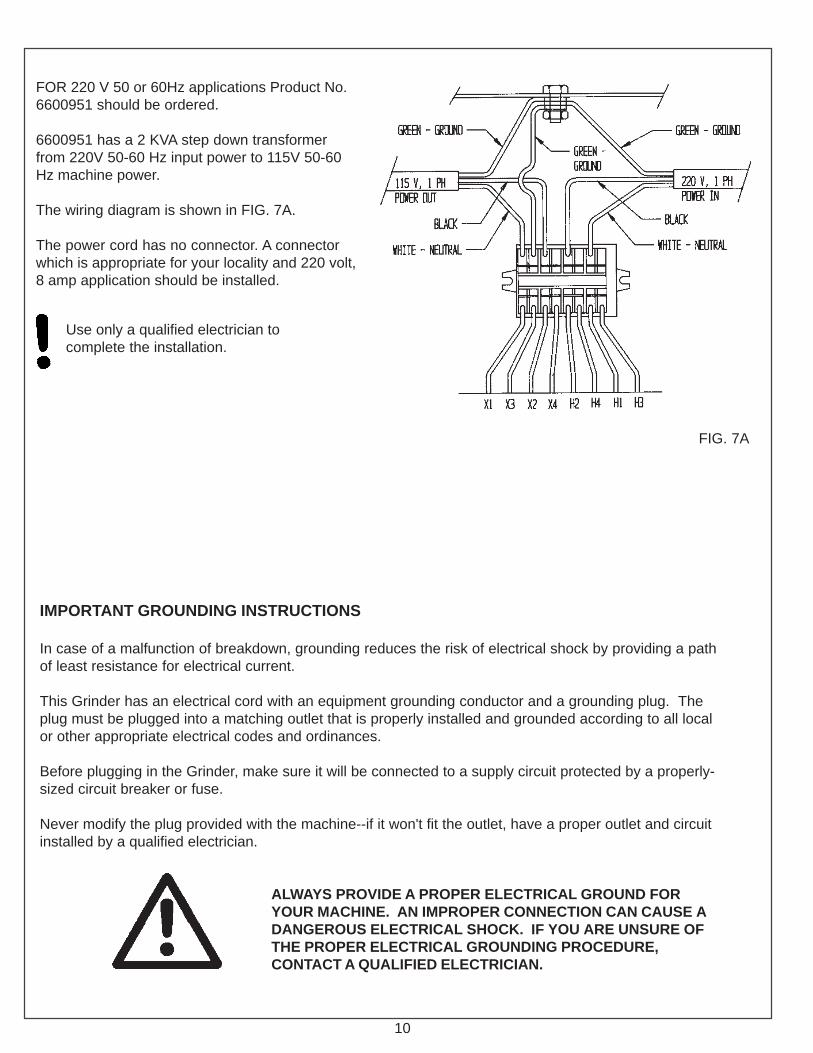
FOR 220 V 50 or 60Hz applications Product No.6600951 should be ordered.
6600951 has a 2 KVA step down transformerfrom 220V 50-60 Hz input power to 115V 50-60Hz machine power.
The wiring diagram is shown in FIG. 7A.
The power cord has no connector. A connectorwhich is appropriate for your locality and 220 volt,8 amp application should be installed.
FIG. 7A
IMPORTANT GROUNDING INSTRUCTIONS
In case of a malfunction of breakdown, grounding reduces the risk of electrical shock by providing a pathof least resistance for electrical current.
This Grinder has an electrical cord with an equipment grounding conductor and a grounding plug. Theplug must be plugged into a matching outlet that is properly installed and grounded according to all localor other appropriate electrical codes and ordinances.
Before plugging in the Grinder, make sure it will be connected to a supply circuit protected by a properly-sized circuit breaker or fuse.
Never modify the plug provided with the machine--if it won't fit the outlet, have a proper outlet and circuitinstalled by a qualified electrician.
ALWAYS PROVIDE A PROPER ELECTRICAL GROUND FORYOUR MACHINE. AN IMPROPER CONNECTION CAN CAUSE ADANGEROUS ELECTRICAL SHOCK. IF YOU ARE UNSURE OFTHE PROPER ELECTRICAL GROUNDING PROCEDURE,CONTACT A QUALIFIED ELECTRICIAN.
Use only a qualified electrician tocomplete the installation.

11
This Page Left Intentionally Blank for Note Taking Purposes

12
ALWAYS READ THE MATERIALSAFETY DATA SHEET (MSDS) FORTHE COOLANT YOU ARE USING.BELOW ARE WARNINGS THATAPPLY TO MOST COOLANTS.
AVOID CONTACT OF COOLANT WITHEYES: IT WILL CAUSE EYEIRRITATION. WEAR FACE SHIELDOR GOGGLES WHEN HANDLINGCONCENTRATE. IN CASE OFCONTACT, FLUSH EYES WITHWATER FOR 15 MINUTES ANDCONTACT A PHYSICIAN.
AVOID BREATHING MISTS. PROVIDELOCAL VENTILATION. KEEPCONCENTRATED BOTTLE CLOSEDWHEN NOT IN USE.
CONTINUED CONTACT OFCONCENTRATE ON SKIN MAY CAUSEIRRITATION. WASH WITH SOAP ANDWATER AFTER CONTACT.
DO NOT TAKE INTERNALLY. IFINGESTED, CONSULT PHYSICIANAND DO NOT INDUCE VOMITING.
(HAZARD POTENTIAL APPLIES TOCONCENTRATE, AND IS LESS ATNORMAL USE DILUTION.)
Mixing the CoolantMix Part No. 3708620 Coolant in a separate container,at a ratio of 50 parts water to 1 part concentrate. Referalso to the label on the Coolant container. If the coolanttray is empty, this will take about 8gallons of water and1.3 pint of concentrate [30 liters of water, and 0.6 liter ofconcentrate]. Fill with coolant until the coolant level is.25 - .50" [ 6 -12 mm] above the top of the coolantpump.
THE COOLANT RATIO AS SPECIFIED MUST BEUSED. TO HIGH A CONCENTRATION ORLOW A CONCENTRATION WILL CAUSECORROSION AND PERFORMANCEPROBLEMS.
INSTALL THE COOLANT
ASSEMBLY INSTRUCTIONS (Cont.)
13
ASSEMBLY INSTRUCTIONS (Continued)
CHECK THE CARRIAGE TRAVERSE
Visually check that the grinding head will be able to traverseto both sides of the machine without contacting anycomponents.
Manually move the grinding head through a complete cycle.Watch carefully for obstructions to the head travel, and checkthat the grinding motor cord and coolant hose are notstretched.
CHECK THE GRINDING MOTORClose the guard door to connect the interlock. Press START.Check that the grinding head runs properly. Be prepared topress STOP if there is any problem. Also check that thecoolant system functions properly.
MAKE FINAL PREPARATIONS FOR OPERATIONCarefully read the operating instructions in the OperatorsManual.
First, study the pages titled "Getting to Know Your Grinder"and "General Operating Information" for importantbackground explanations about the machine and aboutbedknife grinding. Then, read the "Operating Instructions"pages for step-by-step procedures on mounting thebedknife and grinding its top and front faces.

14
MAINTENANCE
DAILY MAINTENANCE IS SPECIFIED ON PAGE 4OF THE OPERATOR'S MANUAL, AND IS TO BEPERFORMED BY THE OPERATOR. LISTEDBELOW ARE PERIODIC MAINTENANCE ITEMSTO BE PERFORMED BY YOUR COMPANY'SMAINTENANCE DEPARTMENT:
1. Clean the Traverse Rails by wiping down with WD-40or equivalent on a weekly basis.
2. Replace the four foam rail wipers (FIG. 10) every 6months of operation.
3. Clean the interior of the Coolant Tray as necessaryand at least every 6 months.
FIG. 10
Wiper

15
CLEANING AND MAINTENANCE GUIDELINES FOR POLYCARBONATE WINDOWS
Cleaning Instructions
DO NOT USE GASOLINEAdherence to regular and propercleaning procedures is recommendedto preserve appearance and performance.
Washing to Minimize ScratchingWash polycarbonate windows with a mild dish washing liquid detergent and lukewarm water, usinga clean soft sponge or a soft cloth. Rinse well with clean water. Dry thoroughly with a moistcellulose sponge to prevent water spots. Do not scrub or use brushes on these windows.Also, do not use butyl cellosolve in direct sunlight.Fresh paint splashes and grease can be removed easily before drying by rubbing lightly with agood grade of VM&P naphtha or isopropyl alcohol. Afterward, a warm final wash should bemade, using a mild dish washing liquid detergent solution and ending with a thorough rinsingwith clean water.
Minimizing Hairline ScratchesScratches and minor abrasions can be minimized by using a mild automobile polish. Threesuch products that tend to polish and fill scratches are Johnson paste Wax, Novus PlasticPolish #1 and #2, and Mirror Glaze plastic polish (M.G. M10). It is suggested that a test bemade on a corner of the polycarbonate window with the product selected following the polishmanufacturer'sinstructions.
Some Important "DON'TS"
n DO NOT use abrasive or highly alkaline cleaners on the polycarbonate windows.n Never scrape polycarbonate windows with squeegees, razor blades or other sharp
instruments.� Benzene, gasoline, acetone or carbon tetrachloride should NEVER be used on
polycarbonate windows.n DO NOT clean polycarbonate windows in hot sun or at elevated temperatures.
Graffiti Removal
� Butyl cellosolve, (for removal of paints, marking pen inks, lipstick, etc.)� The use of masking tape, adhesive tape or lint removal tools works well for lifting off old
weathered paints.� To remove labels, stickers, etc., the use of kerosene, VM&P naphtha or petroleum spirits
is generally effective. When the solvent will not penetrate sticker material, apply heat(hair dryer) to soften the adhesive and promote removal.
n GASOLINE SHOULD NOT BE USED!
MAINTENANCE (Continued)

16
ADJUSTMENT (Continued)
FIG. 11
TO ADJUST THE CARRIAGE VEE ROLLERSECCENTRIC
The carriage large Vee rollers are adjusted for zerofree play with an eccentric on the single rollerattachment bolt closest to the operator.
To adjust the eccentric, position the Grinding Headand Carriage Assembly to center it on the traverserail center strut assembly. Move the Grinding Headinward with the infeed handwheel to expose the veeroller lock nut. See FIG. 11.
Put a 3/4" wrench on the hex head eccentric boltbottom side. Loosen the top side locknut with a1/2" socket only enough to move the eccentric bolt.The roller spacer washer under the carriage andabove the roller assembly must be completely flushwith no air gaps. If you have air gaps, the eccentricbolt is to loose. With the eccentric bolt and locknutloose only enough to move the eccentric, turn the(3/4" wrench) eccentric bolt only enough to take thefree play out of the large vee rollers. Determinezero free play by grasping the carriage and trying tomove it up and down firmly. Tighten the eccentriconly enough for zero free play. When correct,retighten the top side lock nut. Make certain the rollerspacer and bracket are tightened square to the car-riage with no air gaps, then verify no free play.
DO NOT OVERTIGHTEN THEECCENTRIC. OVERTIGHTENINGCAN OVERLOAD THE TRAVERSESHAFTS AND CAUSE A BADGRIND.
Vee Roller Lock Nut

17
ADJUSTMENTS (Continued)
TO ELIMINATE INFEED HANDWHEELBACKLASH
If there is backlash in the Grinder Head Infeedhandwheel (FIG. 12A), there are two adjustmentpoints on each to check:
1. Washers behind the handwheel:
A. Loosen (about half a turn) the setscrewholding the handwheel to the shaft. This setscrew is accessed by removing the calibrationring set screw and rotating the calibration ringto access the handwheel setscrew.
B. Tighten the hex lock nut which secures thehandwheel to 100 in. lbs. [1.15 kg-m], thenback off 1/2 turn.
C. Check for .015 in. [.04mm] gap betweenthe wave washer and the flat washer. See FIG.12B.Readjust the hex lock nut if necessary.
D. Tighten the setscrew holding the handwheelto the shaft. Install and tighten the calibrationring setscrew.
2. Check the nylon ball tension on theadjustment shaft threads at the grinding headslide. See FIG. 12A. When you turn thehandwheel there should be no free play in thehandwheel before the grinding head slidemoves. If there is free play, tighten thesetscrew that pushes the nylon ball againstthe acme thread of the adjustment shaft. Thenylon ball preloads the free play out of thethreaded joint between the adjustment shaftand the tooling bar slide block. Apply tensiononly enough to zero the free play. DO NOTover tension as the adjuster will be difficultto turn.
FIG. 12A
Setscrew with nylon ball
FIG. 12B
InfeedHandwheel
Wave andflat washers
.015 in. gap
Hex Nut

18
ADJUSTMENTS (Continued)
TO ELIMINATE ALIGNMENT ADJUSTMENTBACKLASH
If there is backlash in the alignment adjustmenthandwheels (FIG. 13A), there are two adjustmentpoints on each to check:
1. Washers behind the handwheel:A. Loosen (about half a turn) the setscrew holding
the handwheel to the shaft.B. Tighten the hex lock nut which secures the
handwheel to 100 in. lbs. [1.15 kg-m], thenback off 1/2 turn.
C. Check for .015 in. [.04mm] gap between thewave washer and the flat washer. See FIG. 13B.Readjust the hex lock nut if necessary.
D. Tighten the setscrew holding the handwheel tothe shaft.
2. Check the nylon ball tension on the adjustmentshaft threads at the tooling bar slide blocks. See FIG.13A. When you turn the handwheel there should beno free play in the handwheel before the tooling barslide block moves. If there is free play, tighten thesetscrew that pushes the nylon ball against the acmethread of theadjustment shaft. The nylon ball preloads the free playout of the threaded joint between the adjustment shaftand the tooling bar slide block. Apply tension onlyenough to zero the free play. Do NOT over tension asthe adjuster will be difficult to turn.The setscrew for the right side tooling bar slide blockis under the protractor decal plate.
FIG. 13A
Setscrew withnylon ball
InfeedHandwheel
Hex Nut
Wave andFlat Wash-ers
.015in. gap
FIG. 13B
19
ADJUSTMENTS (CONTINUED)
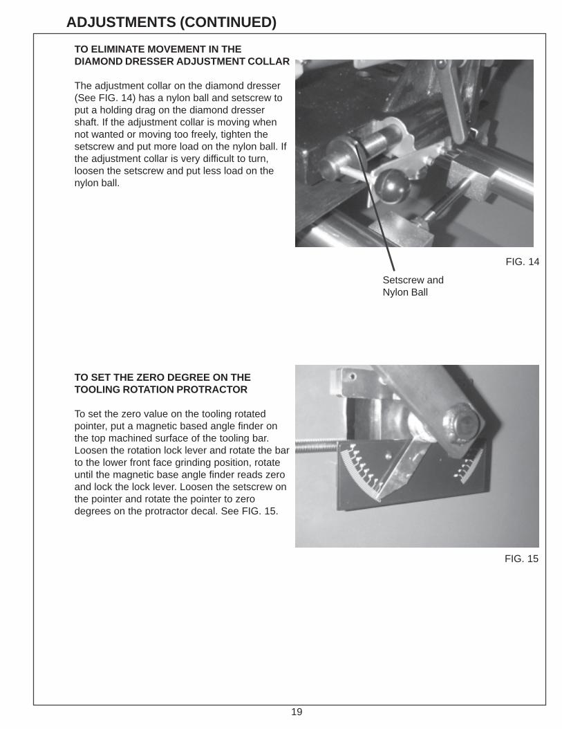
TO ELIMINATE MOVEMENT IN THEDIAMOND DRESSER ADJUSTMENT COLLAR
The adjustment collar on the diamond dresser(See FIG. 14) has a nylon ball and setscrew toput a holding drag on the diamond dressershaft. If the adjustment collar is moving whennot wanted or moving too freely, tighten thesetscrew and put more load on the nylon ball. Ifthe adjustment collar is very difficult to turn,loosen the setscrew and put less load on thenylon ball.
TO SET THE ZERO DEGREE ON THETOOLING ROTATION PROTRACTOR
To set the zero value on the tooling rotatedpointer, put a magnetic based angle finder onthe top machined surface of the tooling bar.Loosen the rotation lock lever and rotate the barto the lower front face grinding position, rotateuntil the magnetic base angle finder reads zeroand lock the lock lever. Loosen the setscrew onthe pointer and rotate the pointer to zerodegrees on the protractor decal. See FIG. 15.
FIG. 14
Setscrew andNylon Ball
FIG. 15

20
ADJUSTMENTS (CONTINUED)
ADJUSTING THE PRELOAD TENSIION ON THESMALL GRINDING HEAD SLIDE VEE ROLLERS
The small grinding head slide vee rollers arepositioned two fixed on the left and one adjustableon the right side. To set the correct preload on theright side adjuster, tighten the setscrew in FIG. 16until the spring is fully compressed solid, then backoff 1/2 turn.
ADJUSTING THE TRAVERSE RAIL CENTERSTRUT ADJUSTMENT
The grinder is equipped with a center strut to main-tain rail spacing against the Large Vee roller ecentricpreload.
To correctly adjust the strut, with no carriage largevee roller eccentric preload and the carriage andgrinding head to one side measure the dimensionover rails at each end of the grinder. Average thetwo values and adjust the center strut to exactly theaverage value and tighten. See FIG. 17 Verify yourready after locking the strut assembly. (p. 16) Nowreset the carriage large vee roller eccentric perinstructions on Page 14.
FIG.16
Tension AdjustSetscrew
FIG. 17

21
Because the guard dooris interlocked to thegrinding motor, thegrinding motor will notoperate if door is open.
TROUBLESHOOTING ELECTRICAL MAIN POWER
--POSSIBLE CAUSE-- --REMEDY-- --REASON----PROBLEM-
A--Main power source breakeris tripped, power source switchis off, or grinder is not plugged in.
B--System Start Switch (SSS) isnot on.
C--Guard door is not closed
D--Grinding motor, start circuit orcoolant pump circuit breaker hastripped
E--Voltage is not going throughinterlock relay.
Grinding motorand coolantpump do notfunction (noapparent powerto machine).
--ELECTRICAL--
Reset breaker, turn switch onand plug machine in.
Press System Start Switch.
Close the guard door.
Reset circuit breaker on end ofcontrol panel.NOTE: If circuit breaker trippingpersists, find the short in theappropriate circuit.
With the guard door closed andthe system start switch latched,check for 115 VAC at terminals0 and 1 on both relays.
If no, consult distributor.
If yes, check for 115VAC atterminal. Relay 2 term.2 to wireBlock Light Blue for grindingmotor. Relay 2 term 6 to wireBlock Light Blue for coolantpump.
If no, consult distributor.

22
A--Grinding wheel loading upwith grinding grit.
B--Too heavy a grind on thefinal grinding pass.
C--Small Grinding Head SlideVee Roller loose
D--Carriage Large Vee Rollersloose.
E--Traverse Rail Center Strutout of adjustment.
TROUBLESHOOTING (Continued) BEDKNIFE GRINDING
--POSSIBLE CAUSE-- --REASON----PROBLEM--
Top face ofbedknife isground in aconvex shape(high in thecenter) or convexshape (high inthe center)
A loaded wheel createsundue pressure on thesurface being ground.Both ends of bedknifemove because of thispressure, allowingbedknife to rock on themiddle support.
For precise grinding,sparking-out process iscritical. It eliminatesexcessive final-grindingpressure on centersand middle support,which helps maintaingrinding straightness.
Looseness in rollercauses erratic grind.
Looseness in rollercauses erratic grind.
Strut holds the shaftsparallel. If not adjustedcorrectly, grind will notbe straight.
Dress the wheel prescribed inthe Operators Manual.
Follow the procedures in theOperators Manual. On thefinal pass, infeed only about.001" [.025 mm]. Let the wheelspark out for 10-20 passes atabout slow speed, with noadditional infeed.
Adjust Vee Rollers per proce-dure on Page 18.
Adjust Vee Roller per proce-dure on Page14.
Adjust center strut perprocedures on Page18.
--REMEDY--

23
TROUBLESHOOTING (Continued) BEDKNIFE GRINDING
--POSSIBLE CAUSE-- --REMEDY-- --REASON----PROBLEM--
A--Grinding wheel rim is notcompletely over the top facebeing ground.
B--Small grinding Head SlideVee Roller loose.
C--Carriage Large Vee Rollersloose
D--Backlash in infeedhandwheel.
Grinding head is traversing toofast.
When the rim doesn'textend over the top face, itwears unevenly and causesgrooves across the bed-knife.
Looseness in rollers causeserratic grind.
Looseness in rollers causeserratic grind.
Backlash allows grindingwheel to move under load.
Traversing speed controlsthe grinding surface texture.A slower traverse producesgrind marks closer together.
The wheel rim must extendover the bedknife top face by1/2" [13 mm] wheneverpossible. See OperatorsManual. If not possible, dressthe wheel more often.
Adjust Vee rollers perprocedure on Page 18.
Adjust Vee Roller perprocedure on Page 14.
Eliminate backlash in infeedhandwheel, see Page 15.
Slow down the traversingspeed.
The top face ofthe bedknife isground unevenlyacross the width.
Too coarsea grind onbedknife.

24
TROUBLESHOOTING (Continued) BEDKNIFE GRINDING
--POSSIBLE CAUSE-- --REMEDY-- --REASON----PROBLEM--
Direct coolant into the grindingwheel, at the point of the grind.See Operators Manual.
Take off about .002 to .003"[.05 to .075mm] per passduring rough grind. SeeOperators Manual.
Dress the wheel before thefinish-grinding pass on eachbedknife. See OperatorsManual.
Dress the wheel before thefinish-grinding pass on eachbedknife. See OperatorsManual.
Take off about .002 to .033"[.05 to .075 mm] per passduring rough grind. SeeOperators Manual.
Speed up traverse.
Visually check the outside-diameter run out while slowlyrotating the wheel. Also checkthe motor without a wheelinstalled. Replace the wheel ifout-of -round.
The top face ofthe bedknifeshows burnmarks from beingtoo hot.
Grinding wheel isglazing tooquickly.
Grinding motorvibrates exces-sively.
When the front face ofthe bedknife gets toohot, the steel loses itstemper (softens).
Too much stockremoval in one passcreates too much heatand softens the steel.
Wheel will glaze if notdressed often enough.Also, as a generalrule, use a highertraverse speed for theheavy grind.
Wheel will glaze if notdressed often enough.If grinding wheel is notextended 1/2" [12 mm]over bedknife, it willglaze more quicklybecause there is lessdressing.
Too light a grinding cutdoesn't permit enoughdressing action on thewheel, so it glazes.
Too slow a traversespeed can causeexcessive heat buildupin the grinding wheel,which glazesthe wheel.
A grinding wheelwhich isn't properlytrued up on outside orinside diameters canvibrate excessivelyand transfer thatvibration to the motor.
A--Coolant not directed ontothe bedknife and grindingwheel.
B--Too heavy stock removalduring grinding.
C--Grinding wheel is glazing.
A--Wheel needs dressing.
B--Too light a cut when roughgrinding.
C--Grinding head is traversingtoo slow.
Grinding wheel is out ofbalance.

25
PARTS LISTS&
EXPLODEDVIEWS

26
6609523 CONTROL PANEL EXPLODED VIEW

27
PARTS LIST 6609523 CONTROL PANELDIAGRAMNUMBER
1 ........................................... B161014................................8-32 X 5/8 Pan Head Machine Screw
2 ........................................... B190813................................10 - 24 X 1/2 Button Head Socket Cap Screw
3 ........................................... B191213................................10 - 24 X 3/4 Button Head Socket Cap Screw
4 ........................................... J197100 ................................10 -24 Locknut Nylon Full
5 ........................................... R000483 ...............................Washer-Lock #10 Int Teeth
6 ........................................... R000553 ...............................Kep Nut 10 -24
7 ........................................... R000558 ...............................Kep Nut 8-32
8 ........................................... 3707009 ................................Strain Relief
9 ........................................... 3707029 ................................Strain Relief
10 ......................................... 3707049 ................................Strain Relief
11 ......................................... 3707439 ................................Terminal Block .25 Spade
12 ......................................... 3707442 ................................Circuit Breaker--2 Amp
13 ......................................... 3707447 ................................Relay 120 Volt
14 ......................................... 3707506 ................................Block--Contact
15 ......................................... 3707507 ................................Latch
16 ......................................... 3707508 ................................Pushbutton--Green Cap
17 ......................................... 3707521 ................................Block--Contact N.C.
18 ......................................... 3707522 ................................Pushbutton--Red Cap
19 ......................................... 3707542 ................................Circuit Breaker--1 amp
20 ......................................... 3707543 ................................Circuit Breaker--12 amp
21 ......................................... 3708448 ................................Decal--Warning Electrical
22 ......................................... 3708650 ................................Decal--Warning Safety
23 ......................................... 6609054 ................................Base-- Control Box
24 ......................................... 6609055 ................................Cover--Control Box
PART NUMBER
PARTDESCRIPTION

28
6609523 CONTROL PANEL WIRING EXPLODED VIEW
29
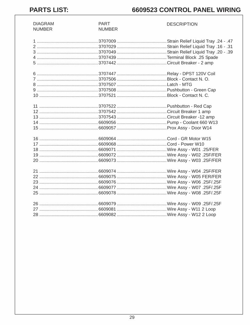
1 .................................................3707009 ........................................Strain Relief Liquid Tray .24 - .472 .................................................3707029 ........................................Strain Relief Liquid Tray .16 - .313 .................................................3707049 ........................................Strain Relief Liquid Tray .20 - .394 .................................................3707439 ........................................Terminal Block .25 Spade5 .................................................3707442 ........................................Circuit Breaker - 2 amp
6 .................................................3707447 ........................................Relay - DPST 120V Coil7 .................................................3707506 ........................................Block - Contact N. O.8 .................................................3707507 ........................................Latch - MTG9 .................................................3707508 ........................................Pushbutton - Green Cap10 ...............................................3707521 ........................................Block - Contact N. C.
11 ...............................................3707522 ........................................Pushbutton - Red Cap12 ...............................................3707542 ........................................Circuit Breaker 1 amp13 ...............................................3707543 ........................................Circuit Breaker -12 amp14 ...............................................6609056 ........................................Pump - Coolant 660 W1315 ...............................................6609057 ........................................Prox Assy - Door W14
16 ...............................................6609064 ........................................Cord - GR Motor W1517 ...............................................6609068 ........................................Cord - Power W1018 ...............................................6609071 ........................................Wire Assy - W01 .25/FER19 ...............................................6609072 ........................................Wire Assy - W02 .25F/FER20 ...............................................6609073 ........................................Wire Assy - W03 .25F/FER
21 ...............................................6609074 ........................................Wire Assy - W04 .25F/FER22 ...............................................6609075 ........................................Wire Assy - W05 FER/FER23 ...............................................6609076 ........................................Wire Assy - W06 .25F/.25F24 ...............................................6609077 ........................................Wire Assy - W07 .25F/.25F25 ...............................................6609078 ........................................Wire Assy - W08 .25F/.25F
26 ...............................................6609079 ........................................Wire Assy - W09 .25F/.25F27 ...............................................6609081 ........................................Wire Assy - W11 2 Loop28 ...............................................6609082 ........................................Wire Assy - W12 2 Loop
PARTS LIST: 6609523 CONTROL PANEL WIRING
DIAGRAMNUMBER
PARTNUMBER
DESCRIPTION

30
6609523 CONTROL PANEL SCHEMATIC

31
THIS PAGE LEFT INTENTIONALLY BLANK FOR NOTE TAKING PURPOSES.

32
6609524 BEDKNIFE SUPPORT EXPLODED VIEW

33
PARTS LIST 6609524 BEDKNIFE SUPPORT
DIAGRAMNUMBER
PARTNUMBER
DESCRIPTION
1 ............................................... B160407 ........................... 8-32 x 1/4 Button Head Socket Cap Screw2 ............................................... B190805 ........................... 10-24 x 1/23 ............................................... B190811 ........................... 10-24 x 1/2 Socket Head Cap Screw4 ............................................... B190813 ........................... 10-24 x 1/2 Button Head Socket Cap Screw5 ............................................... B250611 ........................... 1/4 - 20 x 3/8 Socket Head Cap Screw6 ............................................... B250811 ........................... 1/4 - 20 x 1/2 Socket Head Cap Screw7 ............................................... B251211 ........................... 1/4 - 20 x 3/4 Socket Head Cap Screw8 ............................................... B251611 ........................... 1/4 - 20 x 1 Socket Head Cap Screw9 ............................................... B251616 ........................... 1/4 -20 x 1 Button Head Socket Cap Screw10 ............................................. C310420 ........................... 5/16 - 18 x 1/4 Socket Set Screw11 ............................................. C310820 ........................... 5/16 - 18 x 1/2 Socket Set Screw12 ............................................. H251602 ........................... Pin - Roll .25 Dia. x 1.00 Long13 ............................................. J377000............................ 3/8 - 16 Locknut Jam Nylon14 ............................................. K251501 ........................... 1/4 Lockwasher Split15 ............................................. 3529069 ........................... Spacer .25 ID x .3750 D x .69 L16 ............................................. 3579109 ........................... Nylon Plug 3/16 Dia.17 ............................................. 3589106 ........................... Washer - Flat .39 x 1.38 x .12518 ............................................. 3708148 ........................... Handwheel 4.5 Dia. .38 Bore19 ............................................. 3708415 ........................... Knob - T 2.5 1/2 - 13F20 ............................................. 6009555 ............................ T-Knob Assy. 3/8 - 1621 ............................................. 3708597 ............................ Handle - Adj 3/8 - 16 x 1.9722 ............................................. 3708652 ............................ Washer - Cncl23 ............................................. 3708836 ............................ Spring Compressor .600 Od x 2.5 Long24 ............................................. 3708665 ........................... Washer - Flat .41 x 1.63 x .04725 ............................................. 3709062 ........................... Washer - Cncl .382 x .75 x .03526 ............................................. 3709304 ........................... Washer - Thrust .375 x .81227 ............................................. 6109013 ........................... Shaft - Adjusting Acme Left Hand28 ............................................. 6309050 ........................... Lock Bar- Left Hand Adjuster29 ............................................. 6309051 ........................... Lock Bar - Thread Left Hand Adjuster30 ............................................. 6609087 ............................ Base - Gage Short C'bore31 ............................................. 6609015 ........................... Block - Slide Left Hand32 ............................................. 6609016 ........................... Block - Slide Right Hand33 ............................................. 6609018 ........................... Shaft - Gage34 ............................................. 6609019 ........................... Magnet - Tooling 66035 ............................................. 6609021 ........................... Arm - Center Adjuster36 ............................................. 6609023 ........................... Screw - Gage Lock37 ............................................. 6609024 ........................... Guide - Slide Block38 ............................................. 6609025 ........................... Block - Adj. Mount39 ............................................. 6609038 ........................... Strap - Slide Right Hand40 ............................................. 6609039 ........................... Bar - Lock Slide Right Hand41 ............................................. 6609047 ........................... Plate - Index Decal42 ............................................. 6609048 ........................... Decal - Protractor43 ............................................. 6609069 ........................... Decal - Tooling Handwheel44 ............................................. 6609501 ........................... Knob Assy - T45 ............................................. B254001 ........................... 1/4 - 20 x 2 - 1/2 Hex Head Cap Screw46 ............................................. H253202 ........................... Pin - Roll .25Dia x 2.0 Long47 ............................................. 6609010 ........................... Tooling Bar - Machined48 ............................................. 6609017 ........................... Pin - Tooling Bar Left Hand49 ............................................. 6609503 ........................... Rotate Arm Weldement - Tooling50 ............................................. 3709374 ........................... Handle51 ............................................. 3969065 ........................... Spacer52 ............................................. 6609535 ............................ Mount Weldment - Left Hand53 ............................................. 6609536 ............................ Mount Weldment - Right Hand54 ............................................. 6609538 ........................... Center Assy55 ............................................. 6609544 ........................... Index Brkt Weldement56 ............................................. 6709021 ........................... Tip Gage57 ............................................. C190820 ........................... 10-24 x 1/2 Socket Set Screw

34
6609525 COOLANT PUMP ASSEMBLY EXPLODED VIEW

35
PARTS LIST 6609525 COOLANT PUMP ASSEMBLY
DIAGRAMNUMBER
PARTNUMBER
DESCRIPTION
1 ..................................................... B191611 ................................. 10--24 X 1 Socket Head Cap Screw
2 ..................................................... C161020 ................................. 8-32 x 5/8 Socket Set Screw
3 ..................................................... J167000.................................. 8-32 Locknut Jam Nylon
4 ..................................................... K190001 ................................. #10 Flat Washer
5 ..................................................... K191501 ................................. #10 Lockwasher Split
6 ..................................................... 3679116 .................................. Connector--Shut off Valve
7 ..................................................... 3708339 ................................. Connector--Barbed Insert
8 ..................................................... 3708620 ................................. Coolant--Flood & Mist Pint
9 ..................................................... 3709593 ................................. Connector--Barbed Female
10 ................................................... 3709595 ................................. Valve--Shut Off Needle
11 ................................................... 3709642 ................................. Coolant Line Assy
12 ................................................... 6609044 ................................. Tube--Coolant 1/4 ID x 88"
13 ................................................... 6609046 ................................. Cover--Coolant Pump
14 ................................................... 6609056 ................................. Pump--Coolant 660 W13

36
6609526 LEG ASSEMBLY EXPLODED VIEW

37
PARTS LIST 6609526 LEG ASSEMBLYDIAGRAMNUMBER
PARTNUMBER
DESCRIPTION
1 ..................................... B311213 ......................................5/16 - 18 x .75 Button Head Socket Cap Screw
2 ..................................... B371201 .....................................3/8 - 16 x 3/4 Hex Head Cap Screw
3 ..................................... B374811 ......................................3/8 - 16 x 3 Socket Head Cap Screw
4 ..................................... J317100 ......................................5/16 - 18 Locknut Nylon Full
5 ..................................... J377100 ......................................3/18 - 16 Locknut Hex Nylok
6 ..................................... J501000 ......................................1/2 -13 Hexnut
7 ..................................... K371501 .....................................3/8 Lockwasher Split
8 ..................................... R000454 .....................................Washer - Flat
9 ..................................... 3708666 ......................................Plug - Hole .3/4 Dia.
10 ................................... 3709563 ......................................Leveling - Bolt Adjustable
11 ................................... 3709990 ......................................Decal - Foley United Large
12 ................................... 3889068 ......................................Strap - Anchor
13 ................................... 6609062 ......................................Panel - Leg Center
14 ................................... 6609063 ......................................Pin - Base
15 ................................... 6609560 ......................................Leg Weldment - 660

38
6609528 MAIN BASE ASSEMBLY EXPLODED VIEW

39
PARTS LIST 6609528 MAIN BASE ASSEMBLY
DIAGRAMNUMBER
PARTNUMBER
DESCRIPTION
1 ................................B310813 ................................ 5/16 - 18 X 1/2 Button Head Socket Cap Screw
2 ................................B311001 ................................. 5/15 - 18 x 5/8 Hex Head Cap Screw
3 ................................B311213 ................................. 5/16 - 18 x .75 Button Head Socket Cap Screw
4 ................................C370820 ................................ 3/8 - 16 x 1/2 Socket Set Screw Cup Point
5 ................................ J317000 ................................. 5/16 - 18 Locknut Nylon Jam
6 ................................K311501 ................................. 5/16 Lockwasher Split
7 ................................ J501000 ................................. 1/2 - 13 Hexnut
8 ................................3708378 ................................. Strip - Foam
9 ................................3708649 ................................. Strut - Door
10 ..............................3708664 ................................. Pipe Plug 3/4 NPT
11 ..............................3709990 ................................. Decal - Foley United Large
12 ..............................6609000 ................................. Base - Main Machined
13 ..............................6609031 ................................. Shaft - Carriage Traverse
14 ..............................6609032 ................................. Hinge - Door
15 ..............................6609033 ................................. Door - Tank Cover
16 ..............................6609040 ................................. Block - Brace Front
17 ..............................6609041 ................................. Block - Brace Rear
18 ..............................6609042 ................................. Plate - Door Hinge
19 ..............................6609043 ................................. Shaft - Brace
20 ..............................3709019 ................................. Washer - Thrust

40
6609529 GRINDING HEAD ASSEMBLY EXPLODED VIEW
41
PAR
TS
LIST
6609529 GR
IND
ING
HE
AD
AS
SE
MB
LY
DIAGRAMNUMBER
PARTNUMBER
PARTDESCRIPTION
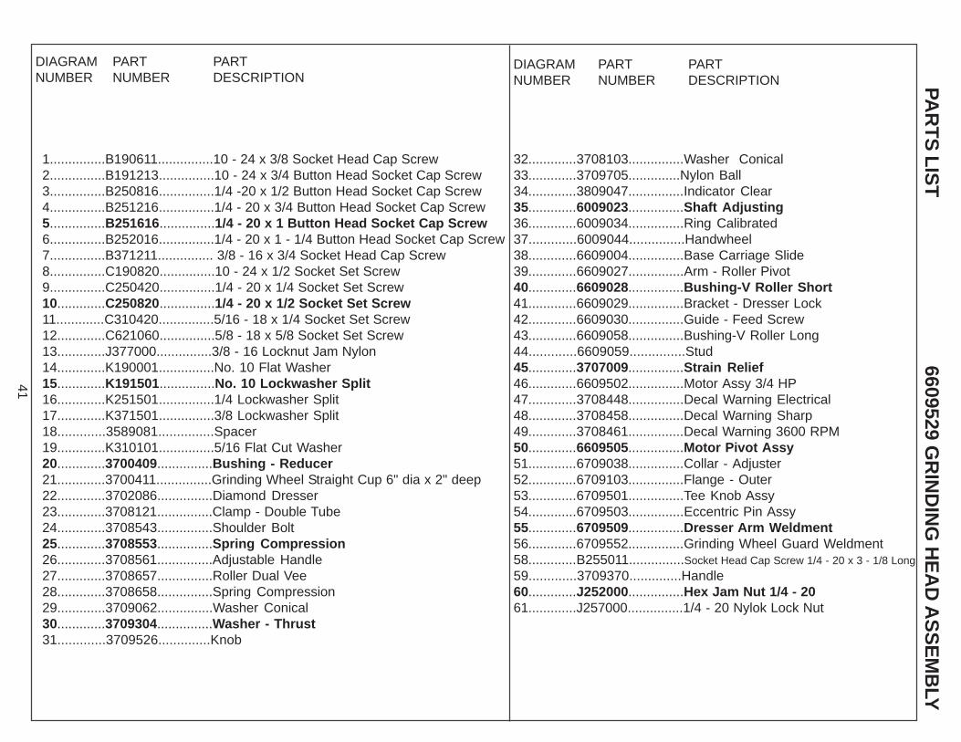
1...............B190611...............10 - 24 x 3/8 Socket Head Cap Screw2...............B191213...............10 - 24 x 3/4 Button Head Socket Cap Screw3...............B250816...............1/4 -20 x 1/2 Button Head Socket Cap Screw4...............B251216...............1/4 - 20 x 3/4 Button Head Socket Cap Screw5...............B251616...............1/4 - 20 x 1 Button Head Socket Cap Screw6...............B252016...............1/4 - 20 x 1 - 1/4 Button Head Socket Cap Screw7...............B371211............... 3/8 - 16 x 3/4 Socket Head Cap Screw8...............C190820...............10 - 24 x 1/2 Socket Set Screw9...............C250420...............1/4 - 20 x 1/4 Socket Set Screw10.............C250820...............1/4 - 20 x 1/2 Socket Set Screw11.............C310420...............5/16 - 18 x 1/4 Socket Set Screw12.............C621060...............5/8 - 18 x 5/8 Socket Set Screw13.............J377000...............3/8 - 16 Locknut Jam Nylon14.............K190001...............No. 10 Flat Washer15.............K191501...............No. 10 Lockwasher Split16.............K251501...............1/4 Lockwasher Split17.............K371501...............3/8 Lockwasher Split18.............3589081...............Spacer19.............K310101...............5/16 Flat Cut Washer20.............3700409...............Bushing - Reducer21.............3700411...............Grinding Wheel Straight Cup 6" dia x 2" deep22.............3702086...............Diamond Dresser23.............3708121...............Clamp - Double Tube24.............3708543...............Shoulder Bolt25.............3708553...............Spring Compression26.............3708561...............Adjustable Handle27.............3708657...............Roller Dual Vee28.............3708658...............Spring Compression29.............3709062...............Washer Conical30.............3709304...............Washer - Thrust31.............3709526..............Knob
DIAGRAMNUMBER
PARTNUMBER
PARTDESCRIPTION
32.............3708103...............Washer Conical33.............3709705..............Nylon Ball34.............3809047...............Indicator Clear35.............6009023...............Shaft Adjusting36.............6009034...............Ring Calibrated37.............6009044...............Handwheel38.............6609004...............Base Carriage Slide39.............6609027...............Arm - Roller Pivot40.............6609028...............Bushing-V Roller Short41.............6609029...............Bracket - Dresser Lock42.............6609030...............Guide - Feed Screw43.............6609058...............Bushing-V Roller Long44.............6609059...............Stud45.............3707009...............Strain Relief46.............6609502...............Motor Assy 3/4 HP47.............3708448...............Decal Warning Electrical48.............3708458...............Decal Warning Sharp49.............3708461...............Decal Warning 3600 RPM50.............6609505...............Motor Pivot Assy51.............6709038...............Collar - Adjuster52.............6709103...............Flange - Outer53.............6709501...............Tee Knob Assy54.............6709503...............Eccentric Pin Assy55.............6709509...............Dresser Arm Weldment56.............6709552...............Grinding Wheel Guard Weldment58.............B255011...............Socket Head Cap Screw 1/4 - 20 x 3 - 1/8 Long
59.............3709370..............Handle60.............J252000...............Hex Jam Nut 1/4 - 2061.............J257000...............1/4 - 20 Nylok Lock Nut

42
6609530 CARRIAGE ASSEMBLY EXPLODED VIEW
Torque to18 ft lbs.
Torque to 18 ft lbs.
Note: At time of installationthe side of the three V rollerswith the groove must betoward the carriage (up).
43
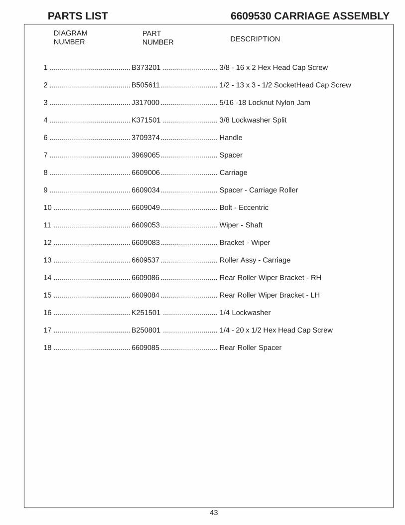
PARTS LIST 6609530 CARRIAGE ASSEMBLY
DIAGRAMNUMBER
PARTNUMBER DESCRIPTION
1 ........................................ B373201 ........................... 3/8 - 16 x 2 Hex Head Cap Screw
2 ........................................ B505611............................ 1/2 - 13 x 3 - 1/2 SocketHead Cap Screw
3 ........................................ J317000 ............................ 5/16 -18 Locknut Nylon Jam
4 ........................................ K371501 ........................... 3/8 Lockwasher Split
6 ........................................ 3709374............................ Handle
7 ........................................ 3969065............................ Spacer
8 ........................................ 6609006............................ Carriage
9 ........................................ 6609034............................ Spacer - Carriage Roller
10 ...................................... 6609049............................ Bolt - Eccentric
11 ...................................... 6609053............................ Wiper - Shaft
12 ...................................... 6609083............................ Bracket - Wiper
13 ...................................... 6609537 ............................ Roller Assy - Carriage
14 ...................................... 6609086 ............................ Rear Roller Wiper Bracket - RH
15 ...................................... 6609084 ............................ Rear Roller Wiper Bracket - LH
16 ...................................... K251501 ........................... 1/4 Lockwasher
17 ...................................... B250801 ........................... 1/4 - 20 x 1/2 Hex Head Cap Screw
18 ...................................... 6609085 ............................ Rear Roller Spacer