Assembly and Operating Manual DDF 2
40
Translation of the original operating manual Assembly and Operating Manual DDF 2 Rotary feed-through
Transcript of Assembly and Operating Manual DDF 2

Translation of the original operating manual
Assembly and Operating ManualDDF 2Rotary feed-through

Imprint
2 06.00 | DDF 2 | Assembly and Operating Manual | en | 389531
ImprintCopyright:This manual is protected by copyright. The author is SCHUNK GmbH & Co. KG. All rightsreserved. Any reproduction, processing, distribution (making available to third parties),translation or other usage - even excerpts - of the manual is especially prohibited andrequires our written approval.
Technical changes:We reserve the right to make alterations for the purpose of technical improvement.
Document number: 389531
Version: 06.00 | 26/10/2020 | en
© SCHUNK GmbH & Co. KGAll rights reserved.
Dear Customer,thank you for trusting our products and our family-owned company, the leadingtechnology supplier of robots and production machines.Our team is always available to answer any questions on this product and other solutions.Ask us questions and challenge us. We will find a solution!Best regards,Your SCHUNK team
Customer ManagementTel. +49-7133-103-2503Fax [email protected]
Please read the operating manual in full and keep it close to the product.

Table of Contents
Table of Contents1 General.................................................................................................................... 5
1.1 About this manual ................................................................................................ 51.1.1 Presentation of Warning Labels ............................................................... 51.1.2 Applicable documents .............................................................................. 61.1.3 Sizes .......................................................................................................... 61.1.4 Variants..................................................................................................... 6
1.2 Warranty .............................................................................................................. 61.3 Scope of delivery .................................................................................................. 61.4 Accessories kit ...................................................................................................... 7
1.4.1 Mechanical connection components accessory pack............................... 71.4.2 Electrical connections accessory pack ...................................................... 7
1.5 Sealing kit ............................................................................................................. 8
2 Basic safety notes ................................................................................................... 92.1 Intended use......................................................................................................... 92.2 Not intended use.................................................................................................. 92.3 Constructional changes ........................................................................................ 92.4 Spare parts ........................................................................................................... 92.5 Ambient conditions and operating conditions ..................................................... 92.6 Personnel qualification....................................................................................... 102.7 Personal protective equipment.......................................................................... 112.8 Notes on safe operation ..................................................................................... 112.9 Transport ............................................................................................................ 112.10 Malfunctions....................................................................................................... 122.11 Disposal .............................................................................................................. 122.12 Fundamental dangers......................................................................................... 12
2.12.1 Protection during handling and assembly .............................................. 132.12.2 Protection during commissioning and operation ................................... 132.12.3 Protection against dangerous movements............................................. 14
2.13 Notes on particular risks..................................................................................... 15
3 Technical data......................................................................................................... 16
4 Assembly ................................................................................................................ 194.1 Mounting the DDF on the robot ......................................................................... 204.2 Connections........................................................................................................ 22
4.2.1 Pneumatic connection............................................................................ 224.2.2 Electrical connection .............................................................................. 22
5 Troubleshooting ..................................................................................................... 265.1 The DDF lets out air when stopped .................................................................... 265.2 DDF is leaking air during operation .................................................................... 265.3 Electric signals are not transmitted.................................................................... 26
306.00 | DDF 2 | Assembly and Operating Manual | en | 389531

Table of Contents
6 Maintenance .......................................................................................................... 276.1 Lubricants/Lubrication points ............................................................................ 276.2 Life span of seals and slip rings........................................................................... 276.3 Dismantle product for seal change..................................................................... 28
6.3.1 Electro-pneumatic and pneumatic feed-through (DDF 2, DDF 2-P) ....... 286.3.2 Electrical feed-through (DDF 2-E) ........................................................... 29
6.4 Servicing and assembling the product................................................................ 296.5 Assembly drawings ............................................................................................. 30
6.5.1 Assembly drawing DDF 2 31/40/50 ........................................................ 306.5.2 Assembly drawing DDF 2 31P/40P/50P .................................................. 316.5.3 Assembly drawing DDF 2 31E ................................................................. 326.5.4 Assembly drawing DDF 2 40-1/50-1/63.................................................. 336.5.5 Assembly drawing DDF 2 40E/50E.......................................................... 346.5.6 Assembly drawing DDF 2 63P ................................................................. 356.5.7 Assembly drawing DDF 2 63E ................................................................. 366.5.8 Assembly drawing DDF 2 80/100/125/160/80-1/100-1 ......................... 376.5.9 Assembly drawing DDF 2 80P/100P/125P/160P .................................... 386.5.10 Assembly drawing DDF 2 80E/100E/125E/160E..................................... 39
4 06.00 | DDF 2 | Assembly and Operating Manual | en | 389531

General
1 General1.1 About this manual
This manual contains important information for a safe andappropriate use of the product.This manual is an integral part of the product and must be keptaccessible for the personnel at all times.Before starting work, the personnel must have read andunderstood this operating manual. Prerequisite for safe working isthe observance of all safety instructions in this manual.Illustrations in this manual are provided for basic understandingand may differ from the actual product design.In addition to these instructions, the documents listed underApplicable documents [} 6] are applicable.
1.1.1 Presentation of Warning Labels
To make risks clear, the following signal words and symbols areused for safety notes.
DANGERDanger for persons!Non-observance will inevitably cause irreversible injury or death.
WARNINGDangers for persons!Non-observance can lead to irreversible injury and even death.
CAUTIONDangers for persons!Non-observance can cause minor injuries.
CAUTIONMaterial damage!Information about avoiding material damage.
506.00 | DDF 2 | Assembly and Operating Manual | en | 389531

General
6 06.00 | DDF 2 | Assembly and Operating Manual | en | 389531
1.1.2 Applicable documents
• General terms of business *• Catalog data sheet of the purchased product *The documents marked with an asterisk (*) can be downloaded onour homepage schunk.com
1.1.3 Sizes
This operating manual applies to the following sizes:• DDF 2 31• DDF 2 40• DDF 2 40-1• DDF 2 50• DDF 2 50-1• DDF 2 63• DDF 2 80• DDF 2 80-1• DDF 2 100• DDF 2 100-1• DDF 2 125• DDF 2 160
1.1.4 Variants
This operating manual applies to the following variations:• DDF 2, with pneumatic and electrical feed-throughs• DDF 2 - P, with pneumatic feed-throughs• DDF 2 - E, with electric feed-throughs
1.2 WarrantyIf the product is used as intended, the warranty is valid for 24months from the ex-works delivery date under the followingconditions:• Observe the specified maintenance and lubrication intervals• Observe the ambient conditions and operating conditionsParts touching the workpiece and wear parts are not included inthe warranty.
1.3 Scope of deliveryThe scope of delivery includes• Rotary feed-through DDF 2 in the version ordered• Accessory pack (mechanical connection)• Accessory pack with cable connector (electrical connection)

General
1.4 Accessories kit
1.4.1 Mechanical connection components accessory packID.-No. of the accessory pack
Accessory pack for ID numberDDF2 31 / 31P / 31E 5522696DDF2 40 / 40P / 40E 5522697DDF2 50 / 50P / 50E 5522697DDF2 63 / 63P / 50-1 / 40-1 5516046DDF2 63E 5522578DDF2 80 / 80P 5516047DDF2 80E / 100E 5522579DDF2 80-1 / 100-1 5516047DDF2 100 / 100P 5516047DDF2 125 / 125P 5516049DDF2 160 5516049
Content of the accessories pack: Assembly drawings [} 30].
1.4.2 Electrical connections accessory pack
Contents:• Plug and socketID.-No. of the accessory pack
Accessory pack for ID numberDDF2 31 / 31E 5516033DDF2 40 / 40E 5516033DDF2 50 / 50E 5516033DDF2 63 / 63E / 50-1 / 40-1 5516034DDF2 80 / 80E / 100E 5516034DDF2 80-1 / 100-1 5516035DDF2 100 5516034DDF2 125 / 125E / 160E 5516035DDF2 160 5516049
706.00 | DDF 2 | Assembly and Operating Manual | en | 389531
General
8 06.00 | DDF 2 | Assembly and Operating Manual | en | 389531
1.5 Sealing kitID.-No. of the seal kit
Seal kit for ID numberDDF2 31 5522796DDF2 31P 5522797DDF2 31E 5522798DDF2 40 / 50 5522799DDF2 40P / 50P 5522800DDF2 40E / 50E 5522801DDF2 63 / 40-1 / 50-1 5522802DDF2 63P 5522803DDF2 63E 5522804DDF2 80 / 100 5522805DDF2 80P / 100P 5522806DDF2 80-1 / 100-1 / 125 / 160 5522808DDF2 80E/ 100E 5522807DDF2 125P / 160P 5522809DDF2 125E / 160E 5522810
Contents of the sealing kit, Assembly drawings [} 30].

Basic safety notes
2 Basic safety notes2.1 Intended use
The rotary feed-through was designed to transfer the energy(electrical signals and air) to the handling module in roboticapplications with endless rotation.• The product may only be used within the scope of its technical
data, Technical data [} 16].• When implementing and operating components in safety-
related parts of the control systems, the basic safety principlesin accordance with DIN EN ISO 13849-2 apply. The proven safetyprinciples in accordance with DIN EN ISO 13849-2 also apply tocategories 1, 2, 3 and 4.
• The product is intended for installation in a machine/system.The applicable guidelines must be observed and complied with.
• The product is intended for industrial and industry-oriented use.• Appropriate use of the product includes compliance with all
instructions in this manual.
2.2 Not intended use• Any utilization that exceeds or differs from the appropriate use
is regarded as misuse.
2.3 Constructional changesImplementation of structural changesBy conversions, changes, and reworking, e.g. additional threads,holes, or safety devices can impair the functioning or safety of theproduct or damage it.• Structural changes should only be made with the written
approval of SCHUNK.
2.4 Spare partsUse of unauthorized spare partsUsing unauthorized spare parts can endanger personnel anddamage the product or cause it to malfunction.• Use only original spare parts or spares authorized by SCHUNK.
2.5 Ambient conditions and operating conditionsRequired ambient conditions and operating conditionsIncorrect ambient and operating conditions can make the productunsafe, leading to the risk of serious injuries, considerable materialdamage and/or a significant reduction to the product's life span.• Make sure that the product is used only in the context of its
defined application parameters, Technical data [} 16].
906.00 | DDF 2 | Assembly and Operating Manual | en | 389531

Basic safety notes
10 06.00 | DDF 2 | Assembly and Operating Manual | en | 389531
2.6 Personnel qualificationInadequate qualifications of the personnelIf the personnel working with the product is not sufficientlyqualified, the result may be serious injuries and significantproperty damage.• All work may only be performed by qualified personnel.• Before working with the product, the personnel must have read
and understood the complete assembly and operating manual.• Observe the national safety regulations and rules and general
safety instructions.
The following personal qualifications are necessary for the variousactivities related to the product:
Trained electrician Due to their technical training, knowledge and experience, trainedelectricians are able to work on electrical systems, recognize andavoid possible dangers and know the relevant standards andregulations.
Qualified personnel Due to its technical training, knowledge and experience, qualifiedpersonnel is able to perform the delegated tasks, recognize andavoid possible dangers and knows the relevant standards andregulations.
Instructed person Instructed persons were instructed by the operator about thedelegated tasks and possible dangers due to improper behaviour.
Service personnel ofthe manufacturer
Due to its technical training, knowledge and experience, servicepersonnel of the manufacturer is able to perform the delegatedtasks and to recognize and avoid possible dangers.

Basic safety notes
2.7 Personal protective equipmentUse of personal protective equipmentPersonal protective equipment serves to protect staff againstdanger which may interfere with their health or safety at work.• When working on and with the product, observe the
occupational health and safety regulations and wear therequired personal protective equipment.
• Observe the valid safety and accident prevention regulations.• Wear protective gloves to guard against sharp edges and
corners or rough surfaces.• Wear heat-resistant protective gloves when handling hot
surfaces.• Wear protective gloves and safety goggles when handling
hazardous substances.• Wear close-fitting protective clothing and also wear long hair in
a hairnet when dealing with moving components.
2.8 Notes on safe operationIncorrect handling of the personnelIncorrect handling and assembly may impair the product's safetyand cause serious injuries and considerable material damage.• Avoid any manner of working that may interfere with the
function and operational safety of the product.• Use the product as intended.• Observe the safety notes and assembly instructions.• Do not expose the product to any corrosive media. This does
not apply to products that are designed for specialenvironments.
• Eliminate any malfunction immediately.• Observe the care and maintenance instructions.• Observe the current safety, accident prevention and
environmental protection regulations regarding the product'sapplication field.
2.9 TransportHandling during transportIncorrect handling during transport may impair the product's safetyand cause serious injuries and considerable material damage.• When handling heavy weights, use lifting equipment to lift the
product and transport it by appropriate means.• Secure the product against falling during transportation and
handling.• Stand clear of suspended loads.
1106.00 | DDF 2 | Assembly and Operating Manual | en | 389531

Basic safety notes
12 06.00 | DDF 2 | Assembly and Operating Manual | en | 389531
2.10 MalfunctionsBehavior in case of malfunctions• Immediately remove the product from operation and report the
malfunction to the responsible departments/persons.• Order appropriately trained personnel to rectify the
malfunction.• Do not recommission the product until the malfunction has
been rectified.• Test the product after a malfunction to establish whether it still
functions properly and no increased risks have arisen.
2.11 DisposalHandling of disposalThe incorrect handling of disposal may impair the product's safetyand cause serious injuries as well as considerable material andenvironmental harm.• Follow local regulations on dispatching product components for
recycling or proper disposal.
2.12 Fundamental dangersGeneral• Observe safety distances.• Never deactivate safety devices.• Before commissioning the product, take appropriate protective
measures to secure the danger zone.• Disconnect power sources before installation, modification,
maintenance, or calibration. Ensure that no residual energyremains in the system.
• If the energy supply is connected, do not move any parts byhand.
• Do not reach into the open mechanism or movement area ofthe product during operation.

Basic safety notes
2.12.1 Protection during handling and assembly
Incorrect handling and assemblyIncorrect handling and assembly may impair the product's safetyand cause serious injuries and considerable material damage.• Have all work carried out by appropriately qualified personnel.• For all work, secure the product against accidental operation.• Observe the relevant accident prevention rules.• Use suitable assembly and transport equipment and take
precautions to prevent jamming and crushing.Incorrect lifting of loadsFalling loads may cause serious injuries and even death.• Stand clear of suspended loads and do not step into their
swiveling range.• Never move loads without supervision.• Do not leave suspended loads unattended.
2.12.2 Protection during commissioning and operation
Falling or violently ejected componentsFalling and violently ejected components can cause serious injuriesand even death.• Take appropriate protective measures to secure the danger
zone.• Never step into the danger zone during operation.
1306.00 | DDF 2 | Assembly and Operating Manual | en | 389531

Basic safety notes
14 06.00 | DDF 2 | Assembly and Operating Manual | en | 389531
2.12.3 Protection against dangerous movements
Unexpected movementsResidual energy in the system may cause serious injuries whileworking with the product.• Switch off the energy supply, ensure that no residual energy
remains and secure against inadvertent reactivation.• Never rely solely on the response of the monitoring function to
avert danger. Until the installed monitors become effective, itmust be assumed that the drive movement is faulty, with itsaction being dependent on the control unit and the currentoperating condition of the drive. Perform maintenance work,modifications, and attachments outside the danger zonedefined by the movement range.
• To avoid accidents and/or material damage, human access tothe movement range of the machine must be restricted. Limit/prevent accidental access for people in this area due throughtechnical safety measures. The protective cover and protectivefence must be rigid enough to withstand the maximum possiblemovement energy. EMERGENCY STOP switches must be easilyand quickly accessible. Before starting up the machine orautomated system, check that the EMERGENCY STOP system isworking. Prevent operation of the machine if this protectiveequipment does not function correctly.
Basic safety notes
2.13 Notes on particular risks
WARNINGRisk of injury from objects falling and being ejected!Falling and ejected objects during operation can lead to seriousinjury or death.• Take appropriate protective measures to secure the danger
zone.
WARNINGRisk of injury due to unexpected movements!If the power supply is switched on or residual energy remains inthe system, components can move unexpectedly and causeserious injuries.• Before starting any work on the product: Switch off the power
supply and secure against restarting.• Make sure, that no residual energy remains in the system.
1506.00 | DDF 2 | Assembly and Operating Manual | en | 389531

Technical data
16 06.00 | DDF 2 | Assembly and Operating Manual | en | 389531
3 Technical dataDesignation DDF 2
31 40 50 63 80 100 125 160Weight [kg] 0.5 0.9 0.95 2.2 5.9 6.1 13.9 14.2Max. rotation speed [min-1] 120 120 120 110 100 100 90 90Max. rotation speed [°/s] 720 720 720 660 600 600 540 540Constant torque [Nm]:pneumatic and electricpneumaticelectric
0.80.80.5
1.51.51.0
1.51.51.0
3.03.02.0
8.08.03.0
8.08.03.0
22.022.011.0
22.022.010.0
Starting torque [Nm](after shutdown):pneumatic and electricpneumaticelectric
1.31.30.7
2.02.01.3
2.02.01.3
4.54.52.0
10.010.03.5
10.010.03.5
25.025.012.0
25.025.012.0
Rotary movement ∞Pressure range for air purge [bar] 0,5 - 1Energy transmissionAir (compressed air up to 10 ba) 2x 2x 2x 4x 4x 4x 4x 4xElectrical energyelectric signals,, with max. 60V; 1A
4x 4x 4x 6x 6x 6x 10x 10x
Noise emission [dB(A)] ≤ 70 ≤ 70 ≤ 70 ≤ 70 ≤ 70 ≤ 70 ≤ 70 ≤ 70
Designation DDF 240-1 50-1 80-1 100-1
Weight [kg] 2.0 2.1 13.1 13.3Max. rotation speed [min-1] 110 110 90 90Max. rotation speed [°/s] 660 660 540 540Constant torque [Nm] 3.0 3.0 22.0 22.0Starting torque [Nm] (after shutdown): 4.5 4.5 25.0 25.0Rotary movement ∞Pressure range for air purge [bar] 0,5 - 1Energy transmissionAir (compressed air up to 10 ba) 4x 4x 4x 4xElectrical energyelectric signals,, with max. 60V; 1A
6x 6x 10x 10x
Noise emission [dB(A)] ≤ 70 ≤ 70 ≤ 70 ≤ 70
Technical data
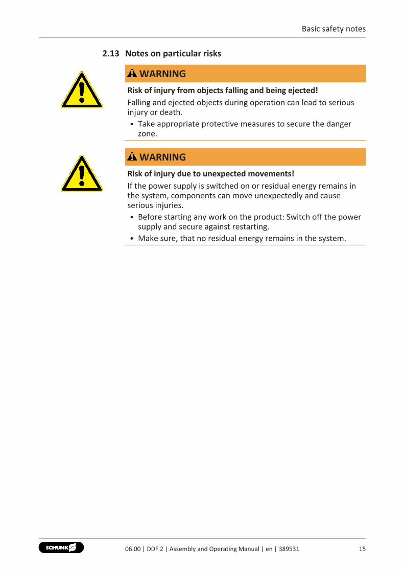
Maximum lateral force
Designation DDF 231
31-P31-E
4040-P40-E
40-1 5050-P50-E
50-1 6363-P63-E
Max. lateral force FQ [N] 60 100 200 100 250 350Max. permitted mountedweight [kg]
6 10 20 10 25 35
Max. dynamic bendingmoment [Nm]MxMyMz
12128
252520
555545
252520
606050
858560
Designation DDF 280
80-P80-E
80-1 100100-P100-E
100-1 125125-P125-E
160160-P160-E
Max. lateral force FQ [N] 1000 1500 1250 1750 2250 2500Max. permitted mountedweight [kg]
100 150 125 175 225 250
Max. dynamic bendingmoment [Nm]MxMyMz
250250180
400400300
290290200
450450350
520520400
550550400
This is the max. total of all loads (acceleration forces and torques,process forces etc.), which can affect a rotary feed-through.
1706.00 | DDF 2 | Assembly and Operating Manual | en | 389531

Technical data
18 06.00 | DDF 2 | Assembly and Operating Manual | en | 389531
Ambient conditions and operating conditions
Designation DDF 2Ambient temperature [°C]min.max.
+5+60
Protection class IP * 54Noise emission [dB(A)] ≤ 70
* For use in dirty ambient conditions (e.g. sprayed water, vapors,abrasion or processing dust) SCHUNK offers correspondingproduct options as standard. SCHUNK also offers customizedsolutions for special applications in dirty ambient conditions.

Assembly
4 Assembly
WARNINGRisk of injury due to unexpected movements!If the power supply is switched on or residual energy remains inthe system, components can move unexpectedly and causeserious injuries.• Before starting any work on the product: Switch off the power
supply and secure against restarting.• Make sure, that no residual energy remains in the system.
1
3
2
4
1 The torque support (shaft) must be mounted on the non-moving housing of the robot.
2 Shaft with shaft-Ø Mounting the DDF on the robot [} 20]3 Bracket on the DDF (included in the DDF scope of delivery)4 The shaft for the torque support (torque pin) should run
precisely parallel to the "middle axis" of the DDF and ata "right angle" (90°) to the bracket.
1906.00 | DDF 2 | Assembly and Operating Manual | en | 389531
Assembly
20 06.00 | DDF 2 | Assembly and Operating Manual | en | 389531
4.1 Mounting the DDF on the robotEvenness of themounting surface
The values apply to the whole mounting surface to which theproduct is mounted.Requirements for evenness of the mounting surface (Dimensions in mm)
Edge length Permissible unevenness< 100 < 0.02> 100 < 0.05
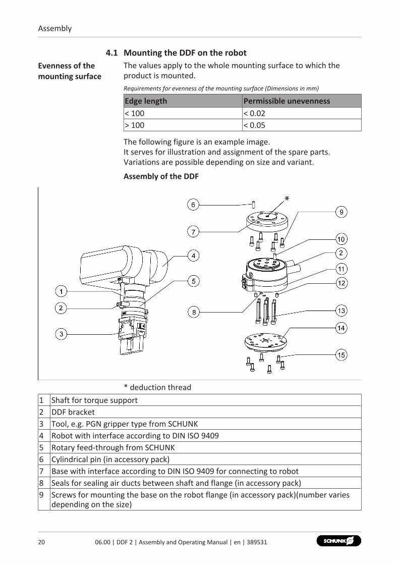
The following figure is an example image. It serves for illustration and assignment of the spare parts.Variations are possible depending on size and variant.
Assembly of the DDF
* deduction thread1 Shaft for torque support2 DDF bracket3 Tool, e.g. PGN gripper type from SCHUNK4 Robot with interface according to DIN ISO 94095 Rotary feed-through from SCHUNK6 Cylindrical pin (in accessory pack)7 Base with interface according to DIN ISO 9409 for connecting to robot8 Seals for sealing air ducts between shaft and flange (in accessory pack)9 Screws for mounting the base on the robot flange (in accessory pack)(number varies
depending on the size)

Assembly
10 Cylindrical pin for positioning the base with shaft11 Shaft completely pre-assembled12 Cylindrical pins for positioning the shaft and flange (only in connection with flange
(14))13 Screws for fastening the shaft onto the base (number varies depending on the size)14 Flange with interface DIN ISO 9409 for tool-mounting (e.g. gripper) (only optional - on
special order)15 Screws for assembly of shaft and flange (only in connection with flange (14))
Shaft-Ø of the torque support
Type Shaft-Ø of the torque supportDDF 2 31 Ø 9 mmDDF 2 40 and 50 Ø 11 mmDDF 2 40-1 and 50-1 Ø 11 mmDDF 2 63 Ø 11 mmDDF 2 80 and 100 Ø 17 mmDDF 2 80-1 and 100-1 Ø 23 mmDDF 2 125 and 160 Ø 23 mm
1. Fasten the base (7) on the robot interface with the screws (9)from the accessory pack.The cylindrical pin (6) from theaccessory pack can be used for centering the base (7).
2. Insert the cylindrical pin (10) into the base.3. Place the completely assembled shaft (11) onto the base.
NOTICE! This pre-assembled unit must not be separated4. Screw together the shaft (11) and the base (7) with the screws (13).5. Insert the seals (8 – for sealing the air ducts) and insert the
cylindrical pins (12) into the shaft.6. Fasten the flange (optional, on special order) with the screws (15)
onto the shaft (11).Screw tightening torques
Screw M5 M6 M8 M10 M12Tightening torque [Nm] 10 Nm 17 Nm 40 Nm 80 Nm 140 Nm
2106.00 | DDF 2 | Assembly and Operating Manual | en | 389531

Assembly
22 06.00 | DDF 2 | Assembly and Operating Manual | en | 389531
4.2 Connections
4.2.1 Pneumatic connection
WARNINGRisk of injury during connection!• Switch off the energy supply.
The precise positions and options for the pneumatic connectionsare shown in the SCHUNK catalog.
Pneumatic connections
1 Pneumatic connections on the robot side2 Pneumatic connections on the tool side3 Air purge connection
4.2.2 Electrical connection
WARNINGRisk of injury due to unexpected movements!If the power supply is switched on or residual energy remains inthe system, components can move unexpectedly and causeserious injuries.• Before starting any work on the product: Switch off the power
supply and secure against restarting.• Make sure, that no residual energy remains in the system.
NOTEElectrical energy: – max. 60 volts, 1 amp

Assembly
4.2.2.1 Connector assignment / connection cable
1 Tool side: adapter plate socket2 Robot side: adapter plate plug
Connector assignment, connection cable
Size Adapter plate socket Adapter plate plug Pin no. Wire strandDDF 231 / 40 / 50
Note: Special cable, pleasecontact SCHUNK.
DDF 240-1 / 50-1 /63 / 80 /100
1 White2 Brown3 Green4 Yellow5 Grey6 Pink7 not assigned
DDF 280-1 /100-1 /125-1 /125 / 160
A WhiteB BrownC GreenD YellowE GreyF PinkG BlueH RedJ BlackK VioletL Grey/Pink, not assignedM Red/Blue, not assigned
2306.00 | DDF 2 | Assembly and Operating Manual | en | 389531
Assembly
24 06.00 | DDF 2 | Assembly and Operating Manual | en | 389531
4.2.2.2 Repositioning cable outlet
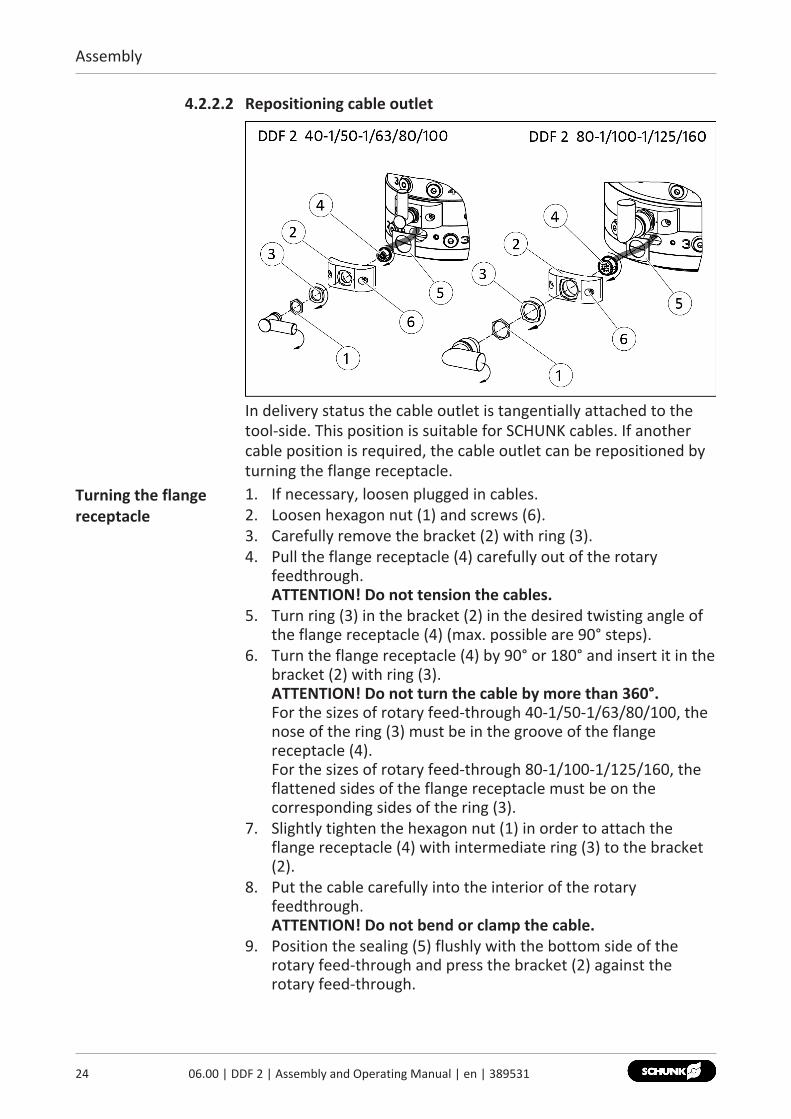
In delivery status the cable outlet is tangentially attached to thetool-side. This position is suitable for SCHUNK cables. If anothercable position is required, the cable outlet can be repositioned byturning the flange receptacle.
Turning the flangereceptacle
1. If necessary, loosen plugged in cables.2. Loosen hexagon nut (1) and screws (6).3. Carefully remove the bracket (2) with ring (3).4. Pull the flange receptacle (4) carefully out of the rotary
feedthrough.ATTENTION! Do not tension the cables.
5. Turn ring (3) in the bracket (2) in the desired twisting angle ofthe flange receptacle (4) (max. possible are 90° steps).
6. Turn the flange receptacle (4) by 90° or 180° and insert it in thebracket (2) with ring (3).ATTENTION! Do not turn the cable by more than 360°.For the sizes of rotary feed-through 40-1/50-1/63/80/100, thenose of the ring (3) must be in the groove of the flangereceptacle (4).For the sizes of rotary feed-through 80-1/100-1/125/160, theflattened sides of the flange receptacle must be on thecorresponding sides of the ring (3).
7. Slightly tighten the hexagon nut (1) in order to attach theflange receptacle (4) with intermediate ring (3) to the bracket(2).
8. Put the cable carefully into the interior of the rotaryfeedthrough.ATTENTION! Do not bend or clamp the cable.
9. Position the sealing (5) flushly with the bottom side of therotary feed-through and press the bracket (2) against therotary feed-through.

Assembly
10. Glue the screws (6) with screw locking "middle-tight" andtighten them firmly.
11. Firmly tighten the hexagon nut (1).Turning the flangeconnector
In order to reposition the cable outlet on the robot-side, the flangeconnector must be repositioned according to the previouslydescribed steps.
2506.00 | DDF 2 | Assembly and Operating Manual | en | 389531
Troubleshooting
26 06.00 | DDF 2 | Assembly and Operating Manual | en | 389531
5 Troubleshooting5.1 The DDF lets out air when stopped
Possible cause Corrective actionAir connection not installed correctly. Tighten air connection. Pneumatic
connection [} 22]Unused air connections open. Close unused air connections.
5.2 DDF is leaking air during operationPossible cause Corrective actionComponents have come loose e.g. due tooverloading.
Send product with a SCHUNK repair order ordismantle product.
5.3 Electric signals are not transmittedPossible cause Corrective actionCable connected incorrectly. Check circular connections and both
miniature flat connections on the right seat.Strands swapped. Check pin allocation.Bus signals should be transmitted. Bus signals can not be transmitted.Slip ring defective. Send the product to SCHUNK with a repair
order.

Maintenance
6 Maintenance6.1 Lubricants/Lubrication points
SCHUNK recommends the lubricants listed.During maintenance, treat all greased areas with lubricant. Thinlyapply lubricant with a lint-free cloth.
Lubricant point LubricantAll seals Renolit HLT 2
6.2 Life span of seals and slip rings
CAUTIONMaterial damage due to hardening lubricants!Lubricants harden more quickly at temperatures above 60°C,leading to possible product damage.• Reduce the lubricant intervals accordingly.
Life span: Seals / slip rings
Type Seals Slip ringsRevolutions in
millionsRevolutions in
millionsDDF 231 10 6DDF 231P 10DDF 231E 6DDF 240 10 6DDF 240P 10DDF 240E 6DDF 240-1 10 6DDF 250 10 6DDF 250P 10DDF 250E 6DDF 250-1 10 6DDF 263 10 6DDF 263P 10DDF 263E 6DDF 280 8 5DDF 280P 8DDF 280E 5DDF 280-1 6 5DDF 2100 8 5
2706.00 | DDF 2 | Assembly and Operating Manual | en | 389531

Maintenance
28 06.00 | DDF 2 | Assembly and Operating Manual | en | 389531
Type Seals Slip ringsRevolutions in
millionsRevolutions in
millionsDDF 2100P 8DDF 2100E 5DDF 2100-1 6 4DDF 2125 6 4DDF 2125P 6DDF 2125E 4DDF 2160 6 4DDF 2160P 6DDF 2160E 4
6.3 Dismantle product for seal change
6.3.1 Electro-pneumatic and pneumatic feed-through (DDF 2, DDF 2-P)
Position of the item numbers, Assembly drawings [} 30] et seqq.Disassembling 1. Remove all compressed air lines.
2. Disconnect the cable connections.3. Completely unscrew the screws (30).4. Note: Robot flange (3) and shaft (2) are bolted together (21).
Pull the shaft (2) down from the robot flange (3).5. Unscrew the screws (44).6. Note: The tool flange (1) and shaft (2) are screwed (22) and
bolted (20) together.Carefully pull the tool flange (1) out from the shaft (2)
7. Unscrew the screws (22).8. Carefully pull the tool flange (1) out from the shaft (2).9. Slide the shaft (2) carefully out of the ring (4).10. Unscrew the screws (17).11. Slide the sleeves (10 and 14) with the seals carefully out of the
ring (4). Pay attention to the sequence of the sleeves.12. For electro-pneumatic feed-through:
IMPORTANT! Do not touch the contacts of the slip ring uniton the rotor (70) and do not allow impacts to thecomponents. Carefully remove the rotor (70).
13. Remove all seals according to the sealing kit list, Sealing kit[} 8].

Maintenance
6.3.2 Electrical feed-through (DDF 2-E)
Position of the item numbers, Assembly drawings [} 30] et seqq.Disassembling 1. Disconnect the cable connections.
2. Completely unscrew the screws (30).3. Note: Tool flange (1) and robot flange (13) are bolted
together (21). Carefully pull the tool flange (1) down from the robotflange (13).
4. For DDF 2-31-E:completely unscrew the screws (22).5. Unscrew the screws (47) and remove the clamping disc (38).6. Unscrew the screws (46) and remove the washer (37).7. Remove bearing (54), clamping sleeve (36) and sealing
ring (104).8. Unscrew washer (8 or 37).9. IMPORTANT! Do not touch the contacts of the slip ring on the
rotor (70) and do not allow impacts to the components.Carefully remove the rotor (70).
10. Remove all seals according to the sealing kit list, Sealing kit[} 8].
6.4 Servicing and assembling the productMaintenance 1. Clean all parts thoroughly and check for damage and wear.
2. Replace all wear parts / seals.✓ The seals are in the enclosed sealing kit. Sealing kit [} 8]
3. Treat all greased areas with lubricant. Lubricants/Lubricationpoints [} 27]
4. Oil or grease bare external steel parts.
Assembly Assembly takes place in the opposite order to disassembly.Observe the following:
CAUTIONDo not damage seals during assembly!
• Unless otherwise specified, secure all screws and nuts withLoctite no. 243 and tighten with the appropriate tighteningtorque.
Screw tightening torques
Screw M5 M6 M8 M10 M12Tightening torque [Nm] 10 Nm 17 Nm 40 Nm 80 Nm 140 Nm
2906.00 | DDF 2 | Assembly and Operating Manual | en | 389531
Maintenance
30 06.00 | DDF 2 | Assembly and Operating Manual | en | 389531
6.5 Assembly drawings
6.5.1 Assembly drawing DDF 2 31/40/50
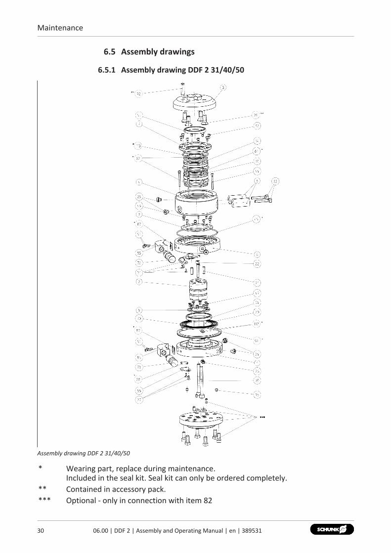
Assembly drawing DDF 2 31/40/50
* Wearing part, replace during maintenance.Included in the seal kit. Seal kit can only be ordered completely.
** Contained in accessory pack.*** Optional - only in connection with item 82

Maintenance
6.5.2 Assembly drawing DDF 2 31P/40P/50P
Assembly drawing DDF 2 31P/40P/50P
* Wearing part, replace during maintenance.Included in the seal kit. Seal kit can only be ordered completely.
** Contained in accessory pack.*** Optional - only in connection with item 82
3106.00 | DDF 2 | Assembly and Operating Manual | en | 389531

Maintenance
32 06.00 | DDF 2 | Assembly and Operating Manual | en | 389531
6.5.3 Assembly drawing DDF 2 31E
Assembly drawing DDF 2 31E
* Wearing part, replace during maintenance.Included in the seal kit. Seal kit can only be ordered completely.
** Contained in accessory pack.*** Optional - only in connection with item 82

Maintenance
6.5.4 Assembly drawing DDF 2 40-1/50-1/63
Assembly drawing DDF 2 40-1/50-1/63
* Wearing part, replace during maintenance.Included in the seal kit. Seal kit can only be ordered completely.
** Contained in accessory pack.*** Optional - only in connection with item 82
3306.00 | DDF 2 | Assembly and Operating Manual | en | 389531

Maintenance
34 06.00 | DDF 2 | Assembly and Operating Manual | en | 389531
6.5.5 Assembly drawing DDF 2 40E/50E
Assembly drawing DDF 2 40E/50E
* Wearing part, replace during maintenance.Included in the seal kit. Seal kit can only be ordered completely.
** Contained in accessory pack.*** Optional - only in connection with item 82

Maintenance
6.5.6 Assembly drawing DDF 2 63P
Assembly drawing DDF 2 63P
* Wearing part, replace during maintenance.Included in the seal kit. Seal kit can only be ordered completely.
** Contained in accessory pack.*** Optional - only in connection with item 82
3506.00 | DDF 2 | Assembly and Operating Manual | en | 389531

Maintenance
36 06.00 | DDF 2 | Assembly and Operating Manual | en | 389531
6.5.7 Assembly drawing DDF 2 63E
Assembly drawing DDF 2 63E
* Wearing part, replace during maintenance.Included in the seal kit. Seal kit can only be ordered completely.
** Contained in accessory pack.*** Optional - only in connection with item 82

Maintenance
6.5.8 Assembly drawing DDF 2 80/100/125/160/80-1/100-1
Assembly drawing DDF 2 80/100/125/160/80-1/100-1
* Wearing part, replace during maintenance.Included in the seal kit. Seal kit can only be ordered completely.
** Contained in accessory pack.*** Optional - only in connection with item 82
3706.00 | DDF 2 | Assembly and Operating Manual | en | 389531

Maintenance
38 06.00 | DDF 2 | Assembly and Operating Manual | en | 389531
6.5.9 Assembly drawing DDF 2 80P/100P/125P/160P
Assembly drawing DDF 2 80P/100P/125P/160P
* Wearing part, replace during maintenance.Included in the seal kit. Seal kit can only be ordered completely.
** Contained in accessory pack.*** Optional - only in connection with item 82
Maintenance
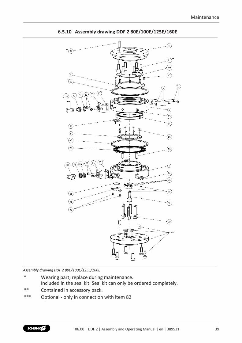
6.5.10 Assembly drawing DDF 2 80E/100E/125E/160E
Assembly drawing DDF 2 80E/100E/125E/160E
* Wearing part, replace during maintenance.Included in the seal kit. Seal kit can only be ordered completely.
** Contained in accessory pack.*** Optional - only in connection with item 82
3906.00 | DDF 2 | Assembly and Operating Manual | en | 389531

Translation of the original operating manual
SCHUNK GmbH & Co. KGClamping and gripping technologyBahnhofstr. 106 - 134D-74348 Lauffen/NeckarTel. +49-7133-103-0Fax [email protected]
Folgen Sie uns I Follow us10
-202
0
© 2
020
SCHU
NK
GmbH
& C
o. K
G
06.0
0 |
DDF
2 |
Asse
mbl
y an
d O
pera
ting
Man
ual |
en
| 38
9531