Assembly and Installation Manual
70
vers. 03 - MY 2010 Assembly and Installation Manual TYPE: ECOWIND 350 ECC MODEL: 350 “C” - AUS 12/24 V AIR-CONDITIONING SYSTEM
Transcript of Assembly and Installation Manual

vers. 03 - MY 2010
Assembly and Installation Manual
TYPE: ECOWIND 350 ECC
MODEL: 350 “C” - AUS 12/24 V
AIR-CONDITIONING SYSTEM


3
SERVICE LOMBARDINI - TEL. 0039 - 0522 / 389550 TEL. 0039 - 0522 / 389547 TEL. 0039 - 0522 / 389568
MANUFACTURER: LOMBARDINI S.r.l.
ADDRESS: Via Cav. Del Lavoro,
A. Lombardini, 2 . 42100 - Reggio Emilia (Italia)
Tel. + 39 - 0522 3891
Telefax + 39 - 0522 389503
E-mail [email protected]
DOCUMENT TYPE: Assembly and Installation Manual
PRODUCT: AIR-CONDITIONING SYSTEM
Pn: 793866 - 793867
TYPE : ECOWIND 350 ECC
MODEL: 350 “C” - AUS 12/24 V
CONFORMITY:
GB

4

5
1 WARNINGS AND GENERAL INFORMATION .............................................................................................6-9
1.1 INTRODUCTION ..............................................................................................................................61.2 RECOMMENDED OIL ...................................................................................................................6-71.3 IDENTIFICATION PLATE ................................................................................................................91.4 DIRECTIVE AND STANDARD REFERENCES APPLIED ................................................................9
2 GENERAL DESCRIPTION AND TECHNICAL DATA ..............................................................................10-14
2.1 TECHNICAL CHARACTERISTICS ...........................................................................................10-122.2 CHARACTERISTICS OF COOLANT .............................................................................................132.3 CONVENTIONAL COOLING CYCLE 350 C ...................................................................................14
3 ASSEMBLY AND INSTALLATION ...........................................................................................................15-59
3.1 REQUIREMENTS AND REGULATIONS FOR ASSEMBLY AND INSTALLATION ........................ 153.2 LIFTING, HANDLING AND INSTALLATION OF THE COMPONENTS .......................................... 163.3 POwER UNIT ASSEMBLY KIT ..................................................................................................16-173.4 POwER UNIT FRAME CLAMP KIT ...........................................................................................18-233.5 INSTALLATION OF CONDENSING UNIT .................................................................................24-313.6 CONNECTION FITTINGS - GAS HOSES ................................................................................32-36
3.7 HOSES AND CABLE CONNECTIONS TO POwER UNIT ........................................................37-393.8 CONNECTING DIESEL TO THE POwER UNIT .......................................................................40-413.9 INSTALLATION OF THE SPLIT UNIT .......................................................................................42-443.10 FASTENING THE PIPES AND CABLES ...................................................................................45-563.11 FILLING THE GAS CIRCUIT wITH R 134A .............................................................................56-57
4 DIAGRAMS AND WIRING ........................................................................................................................58-61
4.0 DIAGRAMS AND wIRING 12 V .................................................................................................58-59 DIAGRAMS AND wIRING 24 V .................................................................................................60-61
5 TROUBLESHOOTING ..............................................................................................................................62-67
CONTENTS

6
WARNINGS AND GENERAL INFORMATION - 1
1.1. INTRODUCTION
Important warnings
To safeguard authorised installation technicians, and to prevent the possibility of damage to the equipment, make sure that you are familiar with the entire contents of the instruction manual before performing any operations on the system.
Intended readers of the assembly and installation manual
This manual is for:
- authorised technicians specialized in assembly and installation of the equipment.
Limited liability
ECOwIND by Lombardini declines all responsibility for damage caused to persons or things resulting from incorrect installation of the system.
Storage of the manual
This manual must be intact and fully legible in all parts. Authorised specialist technicians must have access to it during their work.
Storage of the manual
The copyright of this manual is owned by ECOwIND by Lombardini.The text of this manual cannot be used in other printed matter without the written authorisation of ECOwIND by Lombardini.
© ECOwIND by Lombardini
THIS MANUAL IS PROPRIETY OF ECOwIND BY LOMBARDINI – ALL FORMS OF REPRODUCTION, PARTIAL OR OTHERwISE, IS STRICTLY PROHIBITED.
1.2. Recommended oil
PAKELO KRIPTON 10 W 60 - specification API CH-4/CF SL, ACEA E4,E5,E7,B4.
NOTE! Alternatively, we reccomend using the following oil: MOBIL 1 15W50 specification API CF ACEA E4, B4, B3.
The engine could be damaged if allowed to operate with insufficient oil. It is also dangerous to add too much oil as its combustion could sharply increase the rotation speed.
Use a suitable oil in order to protect the engine. The lubrication oil influences the performances and life of the engine in an incredible way. The risk of piston seizure, jammed piston rings and rapid wear of the cylinder liner, the bearings and all moving parts
increases if oil whose characteristics differ from the recommended type is used, or if the oil is not regularly changed. All this notably reduces engine life.
Oil viscosity must suit the ambient temperature in which the engine operates.
Old oil can cause skin cancer if repeatedly left in contact with the skin and for long periods of time. If contact with the oil is inevitable, you are advised to thoroughly wash your hands with soap and water as soon as possible.
Appropriate protective gloves etc should be wore during this operation. Old oil is highly polluting and must be disposed of in the correct way. Do not litter.
LUBRICANT INTERNATIONAL SPECIFICATIONS
They define testing performances and procedures that the lubricants need to successfully respond to in several engine testing and laboratory analysis so as to be considered qualified and in conformity to the regulations set for each lubrication kind.
A.P.I : ( American Petroleum Institute )MIL : Engine oil U.S. military specifications released for logistic reasonsACEA : European Automobile Manufacturers Association

7
SEQUENZE API / MIL - SEQUENCES API / MIL - API / MIL SEQUENCES
API / MIL-SEQUENZEN - SECUENCIAS API / MIL - SEQUÊNCIAS API / MIL
BENZINA - ESSENCE - PETROL BENZIN - GASOLINA
CF CE CD CC SC SD SE SF SG
L- 46152 D / E
SHAPI SJ SLCH-4 CG-4 CF-4
MIL
CF-2
DIESEL
OBSOLETI - OBSOLETECORRENTI - CURRENT
SAE 20W*SAE 30*
SAE 40*SAE 10W-30**
SAE 10W-40**
SAE 10W-60**
SAE 15W-40 **SAE 15W-40 **
SAE 20W-60 **
SAE 5W-30 ***
SAE 0W-30 ***
-30
-25
-20
-15
-10
-5 0
+5
+10
+15
+20
+25
+30
+35
+40
+45
SAE 10W*
+50
-35
-40
SAE 5W-40 ***
SAE 15W-40 *
base mineralebase minéralemineral base
MineralölbasisBase mineralbase mineral
SAE 15W-40 **SAE 20W-60 **
base semi-sinteticabase semi-synthétique
semi-synthetic baseHalbsynthetische Basis
Base semi-sinteticabase semi-sintética
Gradazioni SAE - Viscosité SAE - SAE GradeSAE Viskositätsklasse - Viscosidad SAE - Gradação SAE
SAE 10W-60SAE 5W-30 ***SAE 0W-30 ***
base sinteticabase synthétique
synthetic baseSynthetische Basis
base sinteticabase sintética
1 - WARNINGS AND GENERAL INFORMATION
ACEA REGULATIONS - ACEA SEQUENCES
PETROL HEAVY DUTY DIESEL ENGINES
A1 = Low-viscosity, for frictions reduction E1 = OBSOLETE
A2 = Standard E2 = Standard
A3 = High performances E3 = Heavy conditions (Euro 1 - Euro 2 engines )
LIGHT DUTY DIESEL ENGINES E4 =Heavy conditions (Euro 1 - Euro 2 - Euro 3 engines )
B1 = Low-viscosity, for frictions reduction E5 = High performances in heavy conditions (Euro 1 - Euro 2 - Euro 3 engines )
B2 = Standard
B3 = High performances (indirect injection)
B4 = High quality (direct injection)

8
Fig. 1
Fig. 2
P
WARNINGS AND GENERAL INFORMATION - 1
ATTENTION !!!
The oil quantity for a correct charging is : Qts 1,25 Liters
This quantity has to be strictly respected
ATTENTION !!!
We suggest, after any operation, to refill or replace oil and to alwasy check oil level through proper oil dipstick C.
ATTENTION !!!
Correct oil quantity is when level is near notch MAX, paying particular attention do not overpass it (fig. 2).
ATTENTION !!!
All power unit engines are oil pre-charged.Guarantee that maintenance has been effected is confirmed by an adhesive with oil specifications put on engine valves cover.
9
Fig. 3
1 - WARNINGS AND GENERAL INFORMATION
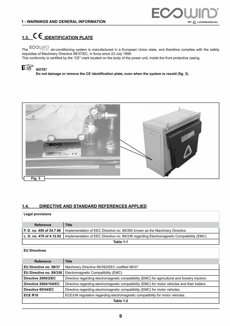
1.3. IDENTIFICATION PLATE
The air-conditioning system is manufactured in a European Union state, and therefore complies with the safety requisites of Machinery Directive 98/37/EC, in force since 23 July 1998.This conformity is certified by the “CE” mark located on the body of the power unit, inside the front protective casing.
NOTE! Do not damage or remove the CE identification plate, even when the system is resold (fig. 3).
1.4. DIRECTIVE AND STANDARD REFERENCES APPLIED
Legal provisions
Reference TitleP. D. no. 459 of 24.7.96 Implementation of EEC Directive no. 89/392 known as the Machinery DirectiveL. D. no. 476 of 4.12.92 Implementation of EEC Directive no. 89/336 regarding Electromagnetic Compatibility (EMC)
Table 1-1
EU Directives
Reference TitleEU Directive no. 98/37 Machinery Directive 89/392/EEC codified 98/37EU Directive no. 89/336 Electromagnetic Compatibility (EMC)Directive 2000/2/EC Directive regarding electromagnetic compatibility (EMC) for agricultural and forestry tractors.Directive 2004/104/EC Directive regarding electromagnetic compatibility (EMC) for motor vehicles and their trailers.Directive 95/54/EC Directive regarding electromagnetic compatibility (EMC) for motor vehicles.ECE R10 ECE/UN regulation regarding electromagnetic compatibility for motor vehicles.
Table 1-2
10
GENERAL DESCRIPTION AND TECHNICAL DATA - 2
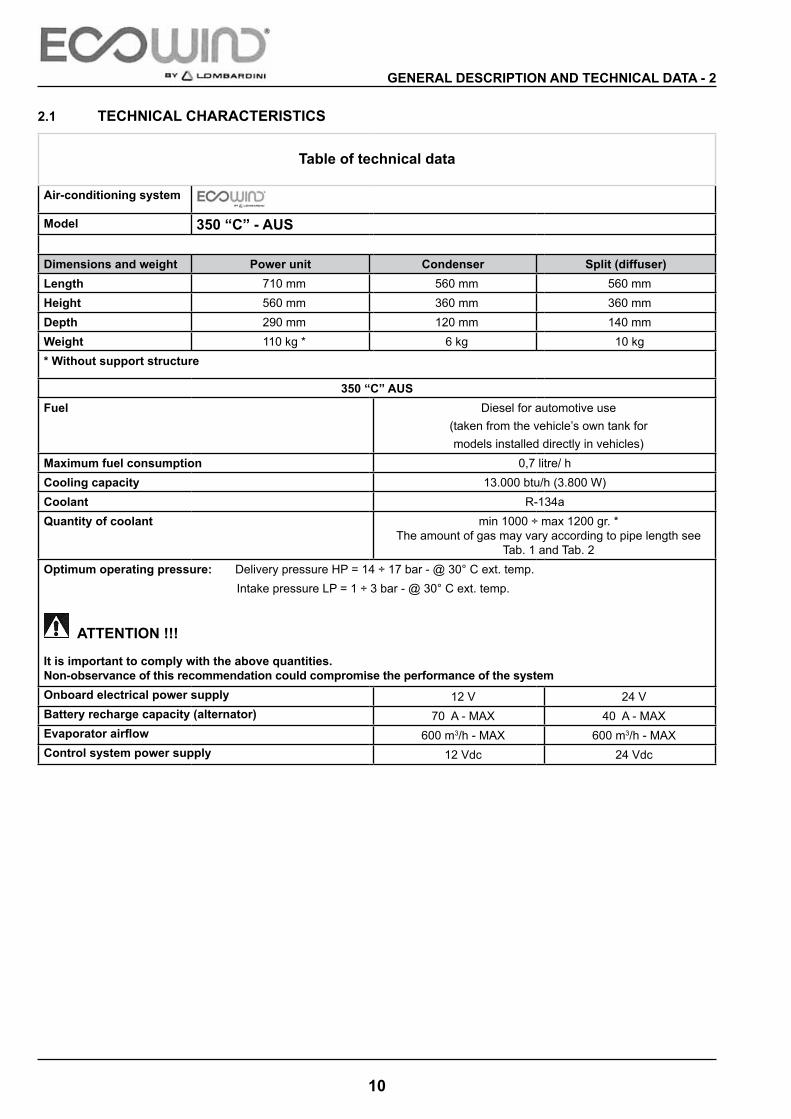
2.1 TECHNICAL CHARACTERISTICS
Table of technical data
Air-conditioning system
Model 350 “C” - AUS
Dimensions and weight Power unit Condenser Split (diffuser)Length 710 mm 560 mm 560 mmHeight 560 mm 360 mm 360 mmDepth 290 mm 120 mm 140 mmWeight 110 kg * 6 kg 10 kg* Without support structure
350 “C” AUSFuel Diesel for automotive use
(taken from the vehicle’s own tank formodels installed directly in vehicles)
Maximum fuel consumption 0,7 litre/ hCooling capacity 13.000 btu/h (3.800 w)Coolant R-134aQuantity of coolant min 1000 ÷ max 1200 gr. *
The amount of gas may vary according to pipe length see Tab. 1 and Tab. 2
Optimum operating pressure: Delivery pressure HP = 14 ÷ 17 bar - @ 30° C ext. temp. Intake pressure LP = 1 ÷ 3 bar - @ 30° C ext. temp.
ATTENTION !!!
It is important to comply with the above quantities.Non-observance of this recommendation could compromise the performance of the systemOnboard electrical power supply 12 V 24 VBattery recharge capacity (alternator) 70 A - MAX 40 A - MAXEvaporator airflow 600 m3/h - MAX 600 m3/h - MAXControl system power supply 12 Vdc 24 Vdc

11
TAB 1
TAB 2
2 - GENERAL DESCRIPTION AND TECHNICAL DATA

12
TAB 3
TAB 4 TAB 5
The AGIP BETULA ESX are synthetic lubricants formulated with selected polyolesters with superior characteristics which make them suitable for lubrication of compressors where HFC refrigerants are used (supplied in Kit)
GENERAL DESCRIPTION AND TECHNICAL DATA - 2
13
2.2 CHARACTERISTICS OF COOLANT
Recommended products: Fluorocarbon coolant R-134a - ( TETRAFLUORETHANE ).
Non-recommended Products: Compressor oil: PAG SP 20 or equivalent ( see chart oil ) Tab 5
ATTENTION !!!
– All coolants not mentioned in the “recommended products” section are not to be considered for use, are inappropriate and hence prohibited.Lombardini S.r.l declines all responsibility for damage to persons or things caused by non-observance of this regulation.
Safety warnings: It is important to observe the following safety regulations when carrying out maintenance on the system:
ATTENTION !!!
fluorocarbon coolants evaporate rapidly, freezing anything with which they come into contact, if accidentally released in liquid form into the atmosphere. Furthermore, in the presence of flames or electrical short circuits, they may produce toxic gases capable of causing serious irritation to the respiratory tract.
Moreover, this kind of coolant tends to displace air, causing a reduction in the level of oxygen and the risk of suffocation. Always take precautions when working with coolants or on air-conditioning systems that contain coolants, particularly in closed or confined spaces.
ATTENTION !!!
First aid treatment in the event of contact with the coolant.
Contact with EYES:
• if there is contact with the liquid, rinse thoroughly with water and seek immediate medical attention.
Contact with SKIN:
• rinse the area with plenty of lukewarm water and stay calm;• wrap the burns in thick, dry, sterile bandages to protect the area from further infections or wounding;• seek medical attention.
INHALATION:
• immediately remove the patient to the open air and, if necessary, help him/her to breathe again;• seek medical attention and remain with the patient until the arrival of professional help.
2 - GENERAL DESCRIPTION AND TECHNICAL DATA
14
Tab. 6
GENERAL DESCRIPTION AND TECHNICAL DATA - 2
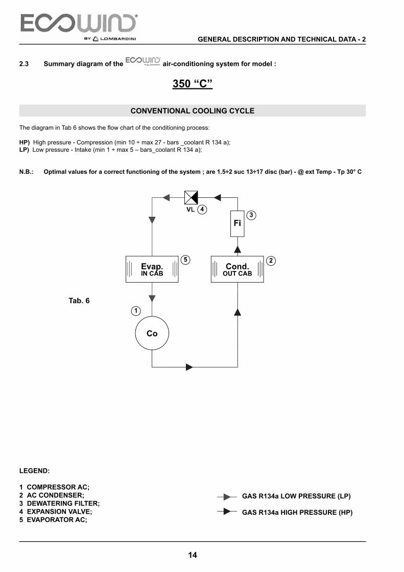
2.3 Summary diagram of the air-conditioning system for model :
350 “C”
CONVENTIONAL COOLING CYCLE
The diagram in Tab 6 shows the flow chart of the conditioning process:
HP) High pressure - Compression (min 10 ÷ max 27 - bars _coolant R 134 a);LP) Low pressure - Intake (min 1 ÷ max 5 – bars_coolant R 134 a);
N.B.: Optimal values for a correct functioning of the system ; are 1.5÷2 suc 13÷17 disc (bar) - @ ext Temp - Tp 30° C
LEGEND:
1 COMPRESSOR AC;2 AC CONDENSER; 3 DEWATERING FILTER;4 EXPANSION VALVE;5 EVAPORATOR AC;
GAS R134a LOW PRESSURE (LP)
GAS R134a HIGH PRESSURE (HP)

15
3.1 REQUIREMENTS AND REGULATIONS FOR ASSEMBLY AND INSTALLATION
Preliminary requirements
Listed below are the fundamental requisites that must be observed by persons installing and assembling the air-conditioning system.
Before proceeding with the operations it is necessary to:
• make sure there exists no critical interference in any of the operating conditions. In particular, make sure that the safety conditions of all moving components are stable;• make sure that parts do not rub together, with the risk of wear, by tightening and positioning correctly;• make sure that there is proper electrical insulation and that fuses and all components on the electrical system are installed correctly; • after loading the coolant, perform a careful inspection for gas leaks and check system pressure;• all operations should be carried following standards of good technical practice;• protect all fissures or perforations made during installation with anti-rust product.
Characteristics of lifting equipment
The power unit should be lifted with equipment that is:
• suitable for the dimensions of the unit;• in good working condition.
ATTENTION !!!Lifting equipment must have a lifting capacity 20% above the weight of the object that is lifted.
Rules for authorised installers
Authorised technicians must observe the following regulations:
• do not linger or pass under the units that are handled during lifting or transport;• do not move or rotate lifted units by their cables or pipes;• use appropriate and safe equipment when working above the vehicle. Do not climb parts of the system or the vehicle.
ATTENTION !!!
Owing to the numerous types of equipment developed for vehicles available on the market, (oversized fuel tanks, custom-built glove compartments etc...) and to the increasingly smaller anchor spaces, the assembly solutions provided in this manual are principally intended for “STANDARD FACTORY” vehicles.It is therefore clear that the assembly solutions to be used for an already customised vehicle (by the customer and/or dealer) must be evaluated by the installer and agreed in advance with the final customer.
3 - ASSEMBLY AND INSTALLATION

16
Fig. 4
3.2 LIFTING, HANDLING AND INSTALLATION OF THE COMPONENTS
Procedure for installation and assembly
ASSEMBLY AND INSTALLATION - 3
Legend:
1. Screw TE UNI 5740.65 M14x25 ..................... n° 42. Screw TE UNI 5740.65 M14x40 ..................... n° 63. Screw TE UNI 5740.65 M14x50 ..................... n° 44. Nut self lock M14 ........................................... n° 105. Nut self lock M6 ............................................. n° 126. washer Ø 15x25x2,5 ...................................... n° 187. Nut self lock M10 ........................................... n° 48. wascher Ø 10 .................................................. n° 4
Screws to fix the frame
Step Description1 Make sure the vehicle is on a level surface and is at a complete rest.
3.3 POWER UNIT ASSEMBLY KIT
INSTALLATION OF THE SUPPORT STRUCTURE OF THE POWER UNIT

17
Fig. 5
SF 1
F 2
Tab. 7
3 - ASSEMBLY AND INSTALLATION
ATTENTION ! ! !
Assemble the entire support structure on the workbench before attaching it to the frame.
WARNING
The holes, F1 and F2 indicate on brackets “7” are not drilled, because their to be drilled during the installation and also must be considered the kind of vehicle frame .The minimum height H recommended of power unit frame S to the floor, must be at measurement as showed in fig. 6 pag. 18.

18
Fig. 6
Fig. 7
H = 300 mm (min)GROUND
S
FFrame Truck
FFrame Truck
S25 mm min
25 mm min
n° 4 hole Ø 15 mm
STEP 2
STEP 1
ASSEMBLY AND INSTALLATION - 3
3.4 MOUNTING DIRECTLY TO THE SIDE FRAME
After mounting on bench the power unit frame S , attach the vertical bracket V at the vehicle frame F as reported on fig. 6.
WARNINGWe advice to install the frame power unit S with a deep H not less at 300 mm for more safety against the conformation of kind of floor.
After the operation to position the frames S regarding F, to drill four holes of 15 mm diameter as showed in fig. 7
WARNINGFor a correct installation of frame S, we recommended to drill at measurements as indicate in fig. 7.

19
N° 4 TE M 14x50
Fig. 8
F
S
3 - ASSEMBLY AND INSTALLATION
Step Description3 Fix the frame power unit S to the frame vehicle F
see fig. 8, using the bolts supplied as reported on the exploded fig. 4 pag.16 positions 1÷8, and torque with values on tab. pag. 17

20
1
2
3
Fig. 12
2
1
3
K
G
C
Fig. 11
Fig. 10
Fig. 9
D
ASSEMBLY AND INSTALLATION - 3
Power Unit Muffler Bend (fig. 11)
1. Muffler bend2. Coupling box3. Coupling box nuts
Insert Muffler Bend
1. Muffler bend2. Muffler3. Power Unit
Step Description6 Attach the supplied muffler bend to the power unit
muffler. See Figure 12.
Step Description5 Unscrew and discard the four plastic protection D
located under the Power Unit support on the stud M10 K (fig. 10).
Step Description4 Lift the Power Unit using the eyebolts G on the
protective casing C (fig. 9).
21
B
T2
11
1
2
Fig. 16
Fig. 15
Fig. 14
Fig. 13
T1
P
S
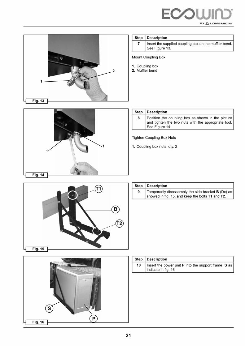
Mount Coupling Box
1. Coupling box2. Muffler bend
Tighten Coupling Box Nuts
1. Coupling box nuts, qty. 2
Step Description7 Insert the supplied coupling box on the muffler bend.
See Figure 13.
Step Description8 Position the coupling box as shown in the picture
and tighten the two nuts with the appropriate tool. See Figure 14.
Step Description9 Temporarily disassembly the side bracket B (Dx) as
showed in fig. 15, and keep the bolts T1 and T2.
Step Description10 Insert the power unit P into the support frame S as
indicate in fig. 16

22
T2
A1
A2
B
C
B
S
B T1
S
Fig. 20
Fig. 19
Fig. 18
Fig. 17
P
K
S
3 - ASSEMBLY AND INSTALLATION
Step Description13 Fix strongly the power unit P at the support frame S
half bolts M 10 supplied end the four threaded stud K. See fig.20, with torque reported on tab. 7 pag. 17.
Step Description12 Fix again the side bracket B at frame S with the bolts
T1 and T2 previously stored as showed in fig. 18 – 19.
Step Description11 Insert the side bracket B before disassembled into
the plastic air intake C thought the two eyes A1 and A2 as showed in fig. 17
Stud M10 (x4)
Stud M10 (x4)

23
Fig. 21
Fig. 22
Fig. 23
oil drain hole
3 - ASSEMBLY AND INSTALLATION
Attention !!!
When the Power Unit has been fixed, it is advisable to firmly tighten the eyebolts on the protective casing see fig. 23).If choosing to remove them from the protective casing, make sure to tighten the four TBEI M8x20 to support the eyebolts by following the same procedure, in order to avoid a possible noise increase from the diesel engine of the Power Unit.
oil drain cap
. Note weel
In the pictures (fig. 21 and fig. 22) is reported the position to oil drain for maintenance engine

24
B
C
L
L
L
L
C
500 mm
310
mm
Fig. 24 Fig. 25
Fig. 26 Fig. 27
B
M
T
F
V + R
ASSEMBLY AND INSTALLATION - 3
3.5 INSTALLATION OF THE CONDENSING UNIT
1 Disassembly to condenser unit C fig. 24-25 the air plastic cover B complete with fan condenser F , unscrew and keep the bolts N° 4 TCEI M6x16, washer ( V+R ) see fig. 24
2 Place the condenser C on the back of cab and in same time to keep it in horizontal position for a correct mounting.To mark the four point L on the condenser bracket needful to fix the four threaded insert T (supplied) fig. 27 like measurements reported in fig. 26
3 Use a drill to 9 mm, and to drill the four points marked for fix the four threaded insert T, fix the insert threaded T (supplied) on the metal cab using the specific tool M (not supplied) see fig.27

25
C
Fig. 28 Fig. 29
Fig. 30
C
F
D
D
3 - ASSEMBLY AND INSTALLATION
4 Install and fix the condenser C on the back of the cab using the bolts (supplied) F, TE M6x35 and washer Ø 6x18, before the fixing interpose the four spacers D 30 – H 15 (supplied) as showed in fig.29-30
WARNING
If you choose for fixing to condensing unit, in other position on truck (than the recommended on rear cab as before specified), need that the new position is ensured optimum fastening and at the same time in an area where the air cooling condenser is free to flow in the field open to avoid damaging hot air recirculation function compromising optimal works system!

26
S
TG G
Fig. 33
2 Unscrew and scrap the plastic cap TP drier protection F, and then inlet the 100 ml of oil compressor O supplied. see fig. 33-34
Fig. 34
OOTp
F
Fig. 35
3 Insert the gas pipes G6 – G8 and cable wiring CE through the rubbers as showed in fig.35-36Lock the fittings R1 and R2 to the condenser C with torque value like reported on tab. 8 pag.36
Fig. 36
C
R2
R1
G8
G6
G8
G6
CE
GAS PIPES FIXING TO BACK OF THE CAB.
FP
1st OPTION
ASSEMBLY AND INSTALLATION - 3
Fig. 31
1 Disassembly and scrap from the condenser C the two rubbers T and then mounting the new two rubbers (protection pipe) G supplied as showed in fig.31-32
Fig. 32
27
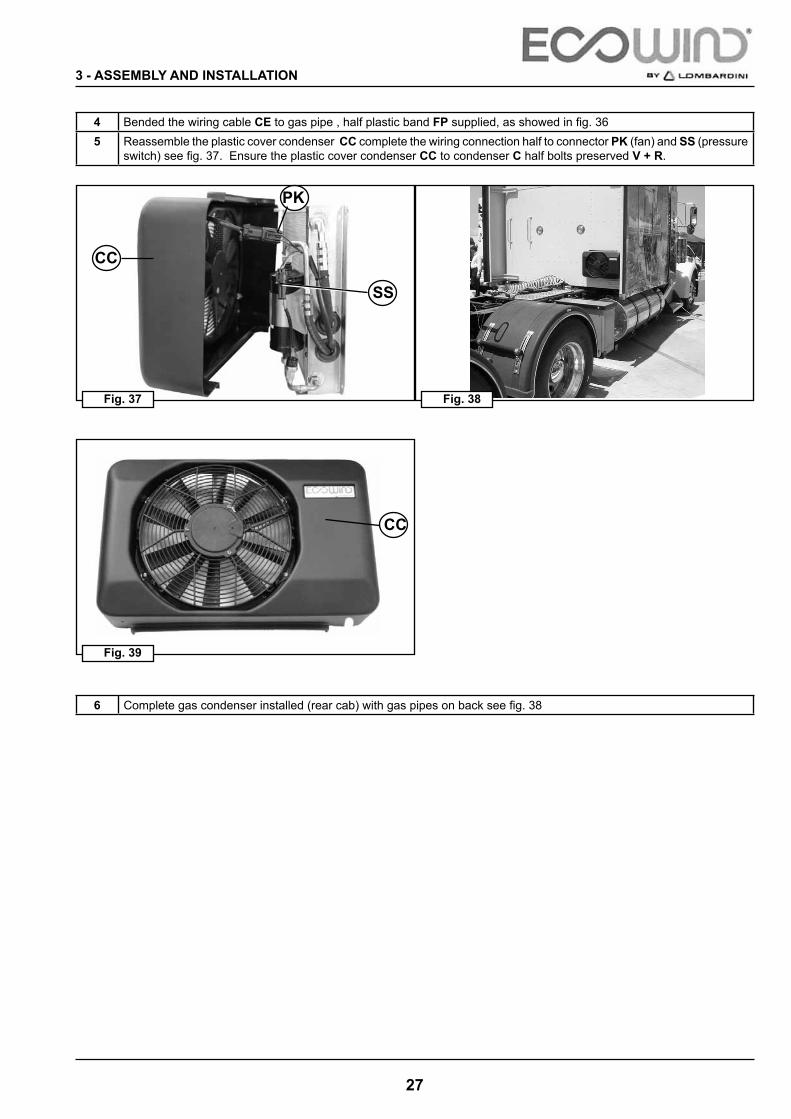
Fig. 37
4 Bended the wiring cable CE to gas pipe , half plastic band FP supplied, as showed in fig. 365 Reassemble the plastic cover condenser CC complete the wiring connection half to connector PK (fan) and SS (pressure
switch) see fig. 37. Ensure the plastic cover condenser CC to condenser C half bolts preserved V + R.
Fig. 38
CC
PK
SS
Fig. 39
CC
6 Complete gas condenser installed (rear cab) with gas pipes on back see fig. 38
3 - ASSEMBLY AND INSTALLATION

28
GAS PIPES FIXING TO SIDE OF THE CAB.
Fig. 40
1 Insert directly the two pipes gas G6 and G8 to condenser C and Lock the fittings R1 and R2 to the condenser C sse. Fig. 40, with torque value like reported on tab. 8 pag.36WARNING: do not disassembly the two rubbers T
C
R2
R1
G8
T
G6
2 Bended the wiring cable CE, to gas pipe half plastic band FP supplied, as showed in fig. 41
Fig. 41
CE
FP
2nd OPTION
ASSEMBLY AND INSTALLATION - 3

29
3 Make the eye on plastic cover condenser CC for crossing pipes gas G6, G8 and wiring cable CE with measurements reported in fig. 42-43
Fig. 42
Fig. 43
50 mm
30 m
m
Ø 34 mm
Air shroud ( Cc) Electric fan (V)
Slot ( K )
Follow the procedure described below using a 34 mm diameter hollow mill fig. 44 and make a hole conforming to the measurements shown in fig. 42Cut out the strip from the casing, removing it towards the outside, to obtain the opening K (fig. 43-45).
Fig. 44 Fig. 45
NB: Operation required only for install pipes, side to condenser Gas C like fig. 40÷41
3 - ASSEMBLY AND INSTALLATION

30
Fig. 46
5 Reassemble at the condenser C the plastic cover condenser CC modified see. Fig. 48 complete with electric connections half connectors PK (fan condenser) and SS (pressure switch) see fig. 46Ensure the plastic cover condenser CC at the condenser C half bolts V + R preserved.
Fig. 47
C
PK
CC
SS
CC
Fig. 48
6 Complete gas condenser installed (rear cab) with gas pipes to side condenser see. fig. 47
ASSEMBLY AND INSTALLATION - 3

31
3 - ASSEMBLY AND INSTALLATION

32
G10 G8 G6
N° 185 N° 160 N° 140
20 mm0,78 inc
18 mm0,70 inc
15 mm0,59 inc
Fig. 49
CX
Q
ASSEMBLY AND INSTALLATION - 3
3.6 CONNECTING FITTINGS - GAS HOSES
NB. Attention
Use CLIC clamps supplied with the equipment, related to correspondent rubber hose external diameters.The CLIC clamp code is indicated on the same.
Step Description1 Insert clamps CX (Clic) into the gas pipes Q, (no. 3 clamps) n° 140 for pipe G6, n° 160 for the pipe G8 and no. n° 185
for pipe G10 as shown in Fig. 49 Then insert the fittings (UNF) into hoses Q, tighten them with the clamps using the special pliers P (Fig. 50-53) not supplied with the equipment.NB: The clamps (Clic) must be positioned as showned on Fig. 56 pag. 34
WARNING
Make sure that the sealing gaskets (OR), provided inside the accessory packet, are correctly seated (fig. 60 pag 36 ).

33
P
NB
Fig. 51Fig. 50
Fig. 53Fig. 52
green
green
P1
3 - ASSEMBLY AND INSTALLATION
WARNING!!
Only use the “clic 205” pliers to tighten the clic clamps (fig. 50 ) Green/Orange. A tight seal between the pipe and the union may not be ensured if this is not respected.
Lombardini is not responsible for any damage to people, animals and things if the tools reported in this manual are not used!!
attention
Lombardini Pn: ED0072 227 0 - Be order separately ( not supplied in Kit Ecowind )Caillau Pn : 54 0 000 205
Alternatively, use pliers P1 Caillau “ Clic 201 “ - Caillau Pn: 54 0 000 201 – Not supplied to Lombardini
green
orange

34
Fig. 56
Fig. 55
Fig. 54
T
C
T
R
C
S
RCF
HR
ASSEMBLY AND INSTALLATION - 3
FITTINGS MOUNTING
Step Description1 Insert the clic clamp C as measurements indicate
in fig. 49 on rubber gas hose T as showed in fig. 54
Step Description2 Concluded the fitting gas R appropriate inside at
rubber gas hose T complete of clic clamp C, see fig.55
Step Description3 Ended insert fitting R operation, ensure that the cir-
clip fitting HR must be attach to the side S of rubber hose T and the stop bracket CF of clic clamp C must be between the two components HR+S as showed in fig. 56.
35
Q
Fig. 59
Fig. 58
Fig. 57
1B
C
F 2 PGreen
Orange
R
P
C
T
CR
3 - ASSEMBLY AND INSTALLATION
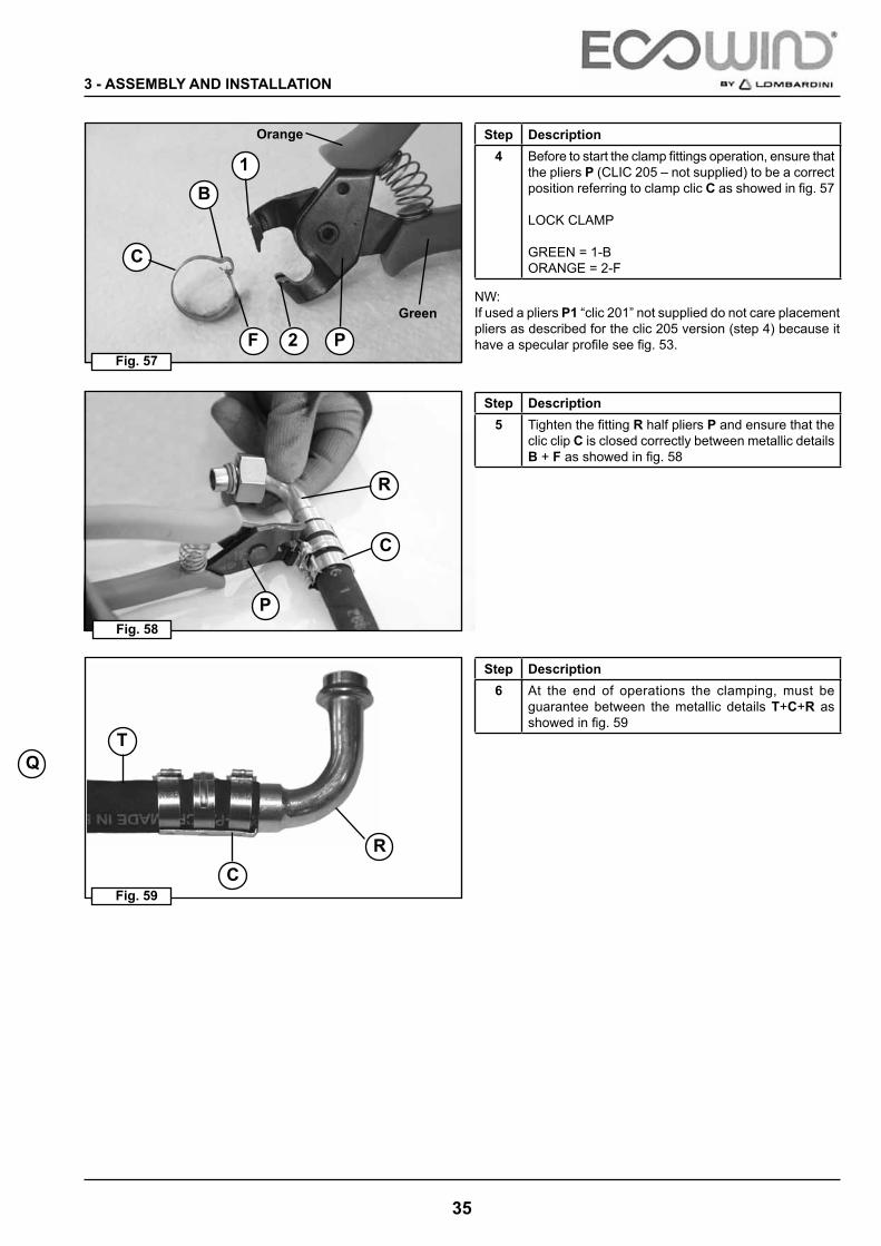
Step Description4 Before to start the clamp fittings operation, ensure that
the pliers P (CLIC 205 – not supplied) to be a correct position referring to clamp clic C as showed in fig. 57
LOCK CLAMP
GREEN = 1-BORANGE = 2-F
Step Description5 Tighten the fitting R half pliers P and ensure that the
clic clip C is closed correctly between metallic details B + F as showed in fig. 58
Step Description6 At the end of operations the clamping, must be
guarantee between the metallic details T+C+R as showed in fig. 59
Nw:If used a pliers P1 “clic 201” not supplied do not care placement pliers as described for the clic 205 version (step 4) because it have a specular profile see fig. 53.
36
OR
Fig. 60
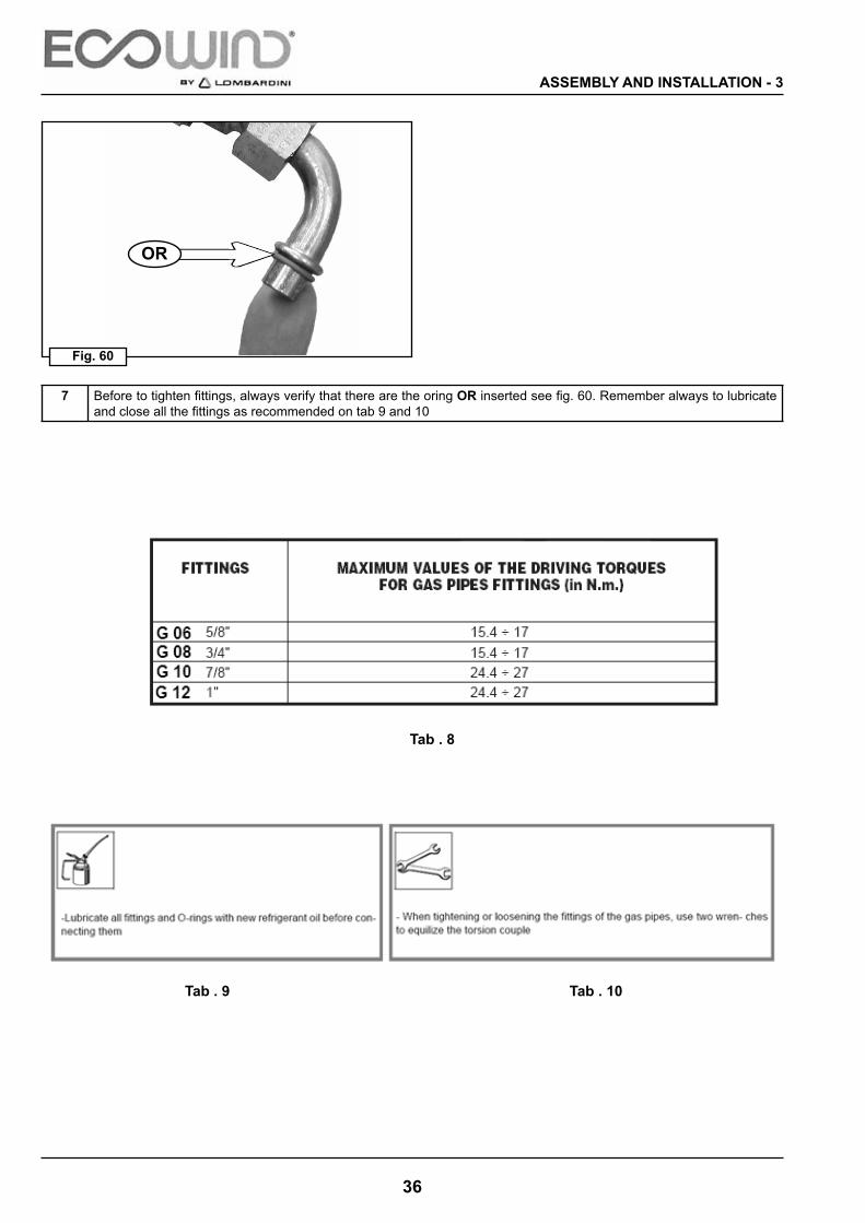
7 Before to tighten fittings, always verify that there are the oring OR inserted see fig. 60. Remember always to lubricate and close all the fittings as recommended on tab 9 and 10
Tab . 8
Tab . 9 Tab . 10
ASSEMBLY AND INSTALLATION - 3

37
Tg In
Tg Out
R
G 8G 8
G 10
Fc
G 10
2c
Fig. 64Fig. 63
Fig. 62Fig. 61
ATTENTION! ! !
The diesel fuel on/off cock “R” (supplied), which is a system safety device, must be connected to the diesel fuel pipe “IN” (fig. 63), see also fig. 73 pag. 41.Lombardini declines all responsibility for damage caused as a result of non-observance of the safety system.
Step Description4 The connector bundle 2c (fig. 64) must be connected to the respective FRAMATOME 3c connectors of the extension
P supplied fig. 66.
Step Description3 Both diesel fuel couplings Tg in – Tg out must be connected by means of the supplied Ø 5 rubber hose to the corre-
sponding couplings on the diesel fuel suction pipe (see fig. 73 on page 41) and clamps supplied.
Step Description1 Connect the gas delivery pipe G8 (fig. 62) to the Power Unit using a 90° union supplied.2 Connect the gas suction pipe G10 (fig. 62) to the Power Unit using a 90° union supplied.
3 - ASSEMBLY AND INSTALLATION
3.7 HOSES AND CABLES CONNECTIONS TO POWER UNIT

38
+ 24
FS
2c
Fc
min 200 A - 12 V
3c
A1
Pa
La
P
+ 12
min 100 A - 24 V
A2
Fig. 68Fig. 67
Fig. 66Fig. 65
ASSEMBLY AND INSTALLATION - 3
Red Cable Black Cable
BATTERY
Step Description5 Connect the cable bundle Fc from the Power Unit to the extension P supplied by inserting FRAMATOME connectors
2c, in the connectors 3c (fig. 65-66).6 Connect the Power Unit’s power cables La to the supplied power cable extension Pa by joining the two connectors A1
and A2. See fig. 65-66. NB: After this operation is complete, it is RECOMMENDED that the two connectors A1 and A2 be secured with a nylon clamp CN, as shown in figure 69.
7 After completing all connections, connect the red cable of the extension (Pa), complete with electrical power fuse FS (fig. 68), to the positive pole of the vehicle’s original batteries (fig. 67).
8Next attach the other eyelet of the black cable Pa of the extension to the negative pole of the battery (fig. 67).WARNING: The black cable must be connected to the battery!!! And not to the frame!!!
9 WARNING
Make sure the supply red cable is firmly attached ( Pa ) , avoiding points that are mobile or subject to rubbing, and not allowing it to hang, to prevent tearing or contact with the vehicle frame which might cause damage to the electrical/electronic circuit in the system or the vehicle’s battery.

39
12
1
3
Fig. 69
3 - ASSEMBLY AND INSTALLATION
Security Harness Connector
1. Plastic clamps, qty. 22. Connector, power unit side3. Connector, battery power cable
10 After attaching the connectors toghether, insert the two plastic clamps supplied and fasten the battery connectors fig. 69.

40
5 4
1 2 3
*Fig. 70
Fig. 71
Fig. 72
3.8 CONNECTING DIESEL TO THE POWER UNIT
Legend:
1. rubber hose Ø 5 mm ..................................................6 m2. self-threading screws ...............................................qty 53. clamps .....................................................................qty 44. suction pipe .............................................................qty 15. gasket ......................................................................qty 2
Supplied in Kit
ASSEMBLY AND INSTALLATION - 3
1 Find a flat position on the upper part of the vehicle’s tank.
2 Bore using a hollow mill Ø 34 mm, taking care to prevent the cut disc and milling chips from falling into the tank (fig. 71).
3 Bore using a Ø 3 mm bit after tracing the fixing points of the suction pipe, using the gasket G as the template (fig. 72)
41
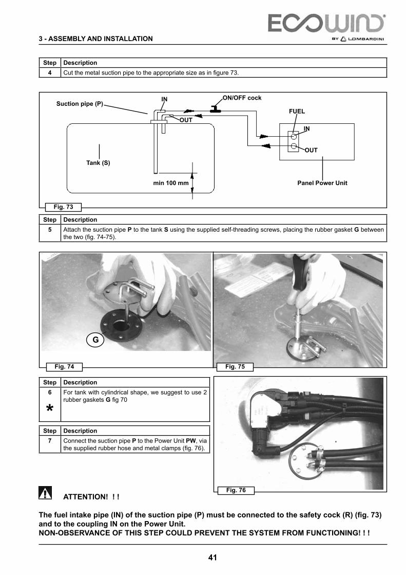
Fig. 73
Fig. 75Fig. 74
Fig. 76
G
min 100 mm
ATTENTION! ! !
The fuel intake pipe (IN) of the suction pipe (P) must be connected to the safety cock (R) (fig. 73) and to the coupling IN on the Power Unit.NON-OBSERVANCE OF THIS STEP COULD PREVENT THE SYSTEM FROM FUNCTIONING! ! !
3 - ASSEMBLY AND INSTALLATION
Suction pipe (P)
Tank (S)
Step Description4 Cut the metal suction pipe to the appropriate size as in figure 73.
Step Description5 Attach the suction pipe P to the tank S using the supplied self-threading screws, placing the rubber gasket G between
the two (fig. 74-75).
Step Description6
*For tank with cylindrical shape, we suggest to use 2 rubber gaskets G fig 70
Step Description7 Connect the suction pipe P to the Power Unit PW, via
the supplied rubber hose and metal clamps (fig. 76).
IN
OUT
OUT
IN
FUEL
Panel Power Unit
ON/OFF cock

42
O
P
P
M
N
Fig. 78Fig. 77
Fig. 79
EC
P
Fig. 80
UP
DOWN
J
3.9 INSTALLATION OF THE SPLIT UNIT
ASSEMBLY AND INSTALLATION - 3
Bore Ø 34
Step Description1 Loosen and remove the 8 self-threading screws N holding the four sides of the cover M and remove it by disconnecting
the connectors C. Take care not to disconnect the cables on the inside split fig. 77-79.
WARNING
The position of the split unit inside the cab must be agreed between the installer and the final customer (vehicle owner) before installation.

43
( * F )
Fig. 83Fig. 82 Fig. 84
Fig. 81
INSTALLATION OF THE SPLIT-UNIT
3 - ASSEMBLY AND INSTALLATION
Bore Ø 50 “R”
Bore Ø 34 “Q”
Bore Ø 34 “S”
n° 9 holes Ø 6 mm
RECOMMENDATION FOR BORING PROCEDURE
3 rubber cable guides G
WARNING!
Pay special attention and take particular care during the drilling phases, to prevent the cab internal upholstery from being damaged!!
Step Description7 After the drilling operations are completed, insert the 3 supplied G rubber cable guides into the holes to 34 mm and made
in the exterior metal of the cab (fig. 84).
Step Description6 Using a hollow mill, bore through the pressed cardboard wall inside the cab and the sheet metal of the rear of the cab,
in the same position as the existing openings on the counter frame for the passage of the following connections: fig. 82 (Q): gas pipes (make opening only in inner wall) Ø 34 mm; (R): electrical system Ø 50 mm; (S): condensation drainage pipe Ø 34 mm.
Step Description2 Position the counter frame O fig. 78 supporting the split unit inside the cab. Use the split unit as a template taking care
to place it against a flat wall and to keep it ABSOLUTELY HORIZONTAL.
WARNINGThe counter frame unit (O) must be correctly positioned in conformance with the above instructions, to prevent condensed water from leaking out.
3 Then mark 9 boring points referring to the holes P on the counter frame and keeping to the measurements shown in the diagram in fig. 81 ( * ).
4 Using a Ø 6mm bit, bore 9 holes in the marked places.5 Firmly secure and attach the counter frame O using the supplied “Graf J” rivets fig. 80.
N.B. : Before attaching the split unit to the cab, make holes to pass pipes and cables !!!
N.B.: The rubber to wiring R are already assembled on the external cable EC
Ø 50 ONLYFOR “R” WIRING CABLE

44
Fig. 85
OK OK NO
ASSEMBLY AND INSTALLATION - 3
Step Description8 During the SPLIT fastening phase, accurately check if the latter is fixed as shown in figure 85, pos. 1.
If the wall inside the cab is tilted on the front, use two bored spacers D with a min. internal Ø of 6.5 mm, (not supplied due to the continuous dimensional variability H).They must be inserted in the two lower pins P on the counter frame, as shown in fig. 78, pos. down.
WARNING!
It is strictly forbidden to fix the SPLIT as shown in fig. 85, pos. 3.Non-observance of this regulation could lead to drainage problems of the condensation produced by the SPLIT that may leak inside the cab.
Lombardini S.r.l declines all responsibility for damage to persons or things caused by non-observance of this regulation.

45
Fig. 86
3 - ASSEMBLY AND INSTALLATION
3.10 FASTENING THE PIPES AND CABLES - Fixed cab version
V cabC condenserS split unitPU power unitPS access points gasB Battery
CONDENSER/CAB METHOD
Pipe G10
Pipe G8
SPLIT cablebattery cable
Pipe
G6
Step Description1 After fixing the Power Unit / Condenser / Split unit, proceed to fasten and close pipes and cables, according to the
following two procedures ( fig 86).
B

46
G 6
R
FG
R
Power Unit
Fig. 88Fig. 87
Fig. 90Fig. 89
CONNECTING PIPES AND CABLES TO THE CONDENSER
ASSEMBLY AND INSTALLATION - 3
Attention!
The condenser mounting operation given above is only indicated for vehicles with a fixed cab (bound to the frame) and not for models with forward tipping cabs!!! Fig 86-90
ECOWIND by Lombardini declines all responsibility for damage caused to things, persons, animals, the vehicle and the ECOWIND system as a result of non-observance of this regulation!!!
Condenser
Step Description1 After fastening the pipes and cables to the vehicle frame, proceed by passing the tube bundle towards the condenser
like options 1st or 2nd to pag 26÷30.2 Continue attaching the pipes on the outside, boring through the rear of the cab using a 3.5mm bit, and inserting the steel/
rubber clamps FG around the pipes. Fasten using the supplied self-threading screws (fig. 87).
Attention!Make sure that the curvature of the pipes R during passage from the vehicle frame to the back of the cab has been checked and is adequate (fig. 89)Non-observance of this point could lead to the pipes being crushed, thereby compromising the performance of the system.

47
Fig. 91
3.10_B FASTENING THE PIPES AND CABLES - Tipping cabs
V cabC condenserS split unitF cab fulcrumPU power unitPS access points gasB Battery
CONDENSER/CAB METHOD
Pipe G10
Pipe G8
split cableBattery cable
Pipe
G6
3 - ASSEMBLY AND INSTALLATION
Step Description1 After fixing the Power Unit / Condenser / Split unit, proceed to fasten and close pipes and cables, according to the fol-
lowing two procedures fig. 91
B

48
Fig. 93
Fig. 92
Fig. 94
Fig. 95
down floor cab
F
ASSEMBLY AND INSTALLATION - 3
Step Description2 After fastening the Power Unit, overturn the vehicle
cabin and fasten the gas pipes and the electrical cables (regardless of the position in which the con-densing unit has been installed) to the vehicle frame using steel, rubber and plastic clamps and a range of nuts and bolts supplied with the system, as far as the rotation fulcrum point F of the cabin, fig 92-93-94.
Step Description5 when the cab rotation fulcrum point F has been rea-
ched (fig. 95), fix the tube bundle to the the cab and down floor cab (fig. 95), boring holes (Ø 3,5 mm) and using steel/rubber clamps along with self-threading screws supplied with the system.
Step Description3
WARNING
While positioning, remember to protect the ends of the GAS G6 / G8 / G10 pipes with adhesive tape, in order to prevent entry of impurities or residues dangerous to the passage of the coolant.
4 when possible, use the existing original tube bundles (fig. 95), in order to use only the plastic clamps sup-plied, to prevent perforation.when this method is used, it is necessary to determine the best passage taking the pipes and electrical cables to the peripherals.

49
FG
Fig. 97
Fig. 96
3 - ASSEMBLY AND INSTALLATION
Step Description6 After fastening the pipes and cables under the cab floor, proceed with the tube bundle towards the condenser. (Attached
previously) fig. 96.7 Continue attaching the pipes on the outside, boring through the rear of the cab using a 3.5 mm bit, and inserting the
steel/rubber clamps FG around the pipes. Fasten using the supplied self-threading screws fig 96.
Step Description8 Pipe and wiring, at the finished installation on the floor and back cab fig. 97

50
G 8
G 10
Fig. 99Fig. 98
Fig. 101Fig. 100
ASSEMBLY AND INSTALLATION - 3
Step Description10
ATTENTION Regardless of the method used to attach the condenser, it is absolutely essential to create the pipe and cable circuit by passing through the cab fulcrum point F, as shown in ( fig. 100 ), in order to avoid serious damage to the system, to parts of the cab and lifting system.
ATTENTION Lombardini S.r.l. declines all responsibility for damage caused to things, persons, animals, the vehicle and the
system as a result of non-observance of this regulation fig. 101.
Step Description9 Gas delivery pipe G8 and inlet pipe G10 must be connected with 180° unions with access points (Fig. 98 L and 99)
necessary for gas recharge AC.The position of the same must be of easy access to allow to insert gas charger station valves.For unions tightening operations see instructions reported

51
P
O
H
G
Fig. 103Fig. 102
Fig. 104
R
D
G6G10
W
3 - ASSEMBLY AND INSTALLATION
Step Description11 After attaching the condenser CO connect the pipes and cables from the condenser to the split unit inside the cab.
Insert pipes G6 – G10, the split command cables W in the hole R and the condensation drainage pipe D in the rubber cable holders G and push them through the slots in the counter frame (fig. 102-103).
Step Description12 Pass them through the internal holes, previously made in the pressed cardboard attached to the counter frame O.
Make sure that the condensation drainage pipe H exits the lower hole (fig. 104).

52
H I
C
DD
Fig. 106Fig. 105
Fig. 108Fig. 107
CC
P
P
S
P
P
Warning!!
Before performing the operation mentioned above, make sure that the condensation drainage pipe (H) is securely fastened to the plastic coupling (I) on the split’s base (fig. 106 ).
Warning!!
INSTALL KIT “ANTIPOLLUTION FILTER D” (SUPPLIED WITH THE EQUIPMENT*) Fig. 108 WITH SELF-THREADING SCREWS C, AS INDICATED IN FIG. 107
Step Description13 Secure the split S to the counter frame O by sliding it onto the 4 Stud M6 P and then fasten it using Ø 6 washers and
the M6 AB nuts provided (fig. 105 )
ASSEMBLY AND INSTALLATION - 3

53
1 2 3 86
9
10
4
5
7
11
12
13
OR
E
Ff
FR
T10
G6G10
Vt
Fig. 109
Fig. 111Fig. 110
Fig. 113Fig. 112
T6
OR
SPLIT CLOSING
3 - ASSEMBLY AND INSTALLATION
Step Description1 Connect the SPLIT/EXTENSION cable connections by joining the FRAMATOME FR connectors (see fig. 110).
Cut rubber hoses T6 and T10 to the right size fig. 112.Insert the couplings and clic clamps (fig. 111) referring to page 32÷36 for the torque.Close the cooling circuit, inserting the fittings G6 and G10 into the expansion valve E, and fasten (fig. 113) using the flange Ff, screw Vt and washer (fig. 113).
LEGEND
1 Condensation drainage pipe2 Union G10 90° FL3 OR G104 Clic clamp 1855 Union G6 90° FL6 OR G67 Clic clamp 1408 Insulating mastic9 Diffuser10 Diffuser support11 Valve flange12 Ø 6 washer13 TCEI M 6x16 Screw
Step Description2 Before tightening the flange on the flanged unions fig. 113, make sure that you have inserted (if not already done) the
supplied OR G6 and G10 (see fig. 112).
54
PCFR
c
Pc
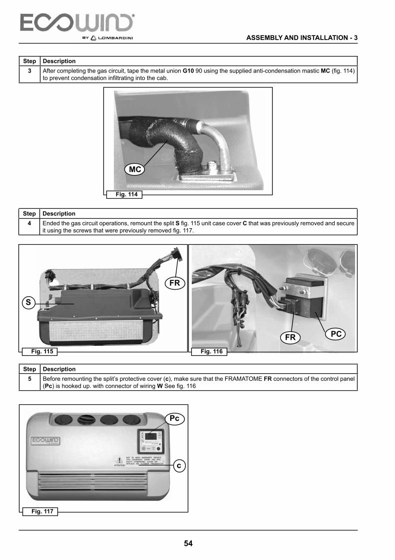
Fig. 114
Fig. 116Fig. 115
Fig. 117
MC
FR
S
Step Description3 After completing the gas circuit, tape the metal union G10 90 using the supplied anti-condensation mastic MC (fig. 114)
to prevent condensation infiltrating into the cab.
ASSEMBLY AND INSTALLATION - 3
Step Description4 Ended the gas circuit operations, remount the split S fig. 115 unit case cover C that was previously removed and secure
it using the screws that were previously removed fig. 117.
Step Description5 Before remounting the split’s protective cover (c), make sure that the FRAMATOME FR connectors of the control panel
(Pc) is hooked up. with connector of wiring W See fig. 116
55
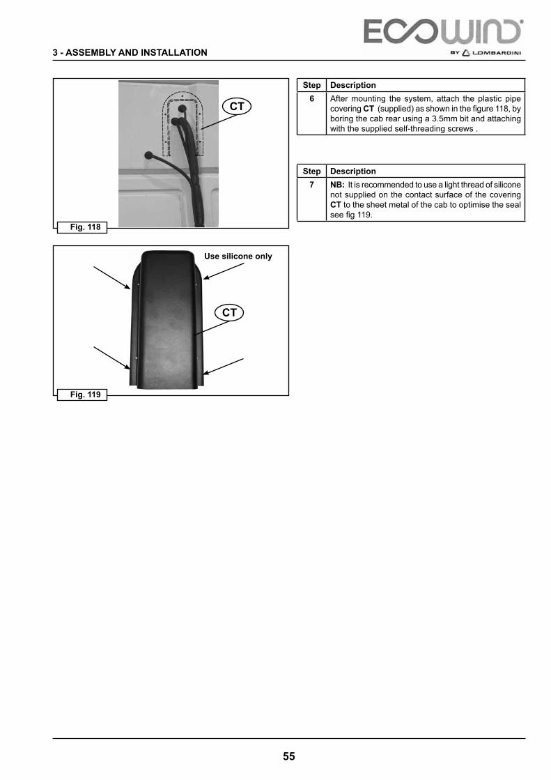
CT
Fig. 119
Fig. 118
CT
3 - ASSEMBLY AND INSTALLATION
Step Description6 After mounting the system, attach the plastic pipe
covering CT (supplied) as shown in the figure 118, by boring the cab rear using a 3.5mm bit and attaching with the supplied self-threading screws .
Step Description7 NB: It is recommended to use a light thread of silicone
not supplied on the contact surface of the covering CT to the sheet metal of the cab to optimise the seal see fig 119.
Use silicone only
56
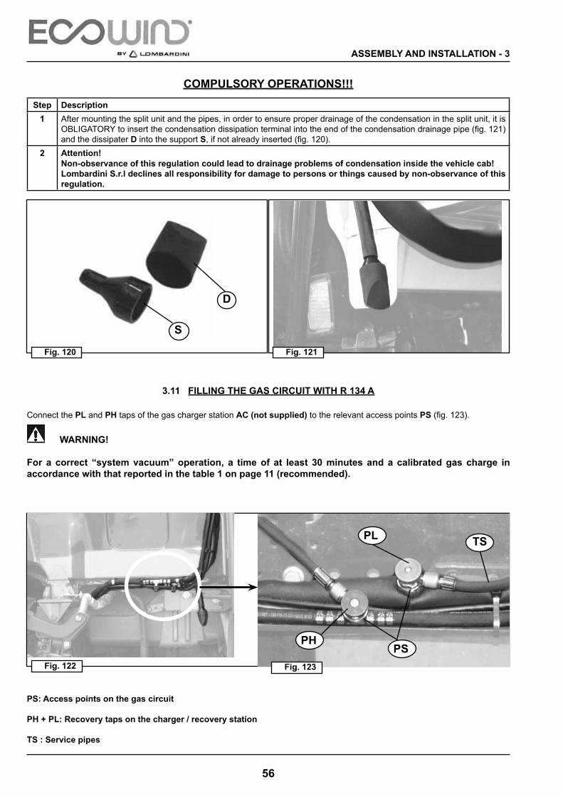
Fig. 122
PL
PS
D
S
TS
Fig. 121Fig. 120
Fig. 123
PH
ASSEMBLY AND INSTALLATION - 3
PS: Access points on the gas circuit
PH + PL: Recovery taps on the charger / recovery station
TS : Service pipes
3.11 FILLING THE GAS CIRCUIT WITH R 134 A
Connect the PL and PH taps of the gas charger station AC (not supplied) to the relevant access points PS (fig. 123).
WARNING!
For a correct “system vacuum” operation, a time of at least 30 minutes and a calibrated gas charge in accordance with that reported in the table 1 on page 11 (recommended).
COMPULSORY OPERATIONS!!!
Step Description1 After mounting the split unit and the pipes, in order to ensure proper drainage of the condensation in the split unit, it is
OBLIGATORY to insert the condensation dissipation terminal into the end of the condensation drainage pipe (fig. 121) and the dissipater D into the support S, if not already inserted (fig. 120).
2 Attention!Non-observance of this regulation could lead to drainage problems of condensation inside the vehicle cab!Lombardini S.r.l declines all responsibility for damage to persons or things caused by non-observance of this regulation.

57
Fig. 124
PL + PH
AC
TS
3 - ASSEMBLY AND INSTALLATION
ATTENTIONAs the system is pressurised, specific operations on the thermodynamic plant must be carried out in full compliance with the regulations for systems containing HFCs and must only be performed by an authorised service centre. Lombar-dini S.r.l declines all responsibility for accidents and/or damage deriving from non-observance of this regulation.
Safety warnings
Frequency of system refilling.
I t is recommended to refi l l the system with R 134 A (TETRAFLUORETHANE) at least once a season, in order to ensure an optimum system performance.
NB: It is extremely important to observe the quantities given on page 10÷11
ATTENTION
PRESSURIZED SYSTEM
Before performing any maintenance operations on the gas circuit, it is absolutely essential to empty the pressurised system (R 134 A) using the specific charger/recovery station.Pay the utmost attention, when disconnecting the TS service pipes as they may contain pressurized coolant!!Avoid direct skin and eye contact with coolant!!
NB: Wear protective goggles and gloves. The coolant has a boiling temperature (in normal environmental conditions) of about
-26 °C (~ -14.8 °F). Non-observance of this regulation could cause burns and serious harm to the
operator!!!
It is strictly forbidden to release and/or dispose of the coolant GAS (R 134a) and the compressor lubricating oil contained in the refrigerating circuit into the environment.
ECOWIND by Lombardini declines all responsibility for damage caused to things, persons, animals or the equipment itself as a result of non-observance of this regulation.
58
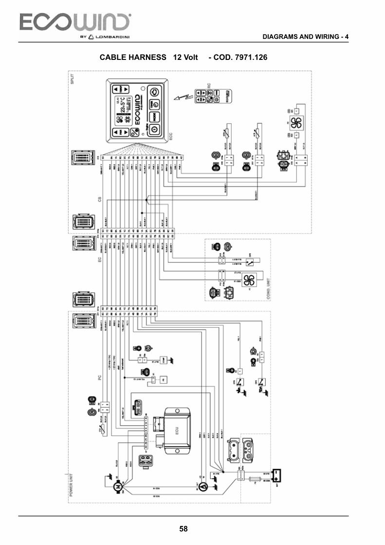
DIAGRAMS AND WIRING - 4
CABLE HARNESS 12 Volt - COD. 7971.126

59
4 - DIAGRAMS AND WIRING
CABLE HARNESS 12 Volt - COD. 7971.126

60
DIAGRAMS AND WIRING - 4
CABLE HARNESS 24 Volt - COD. 7971.127

61
4 - DIAGRAMS AND WIRING
CABLE HARNESS 24 Volt - COD. 7971.127

62
TROUBLESHOOTING - 5
N°
PRO
BLE
MM
ESSA
GE
ICO
NN
OTE
0.a.
1w
ait f
ew m
inut
es f
or E
CU
fuse
rear
m
0.a.
2R
evis
e fu
se F
S if
is n
ecce
ssar
y re
plac
e it
0.a.
3R
evis
e rig
ht c
onne
ctio
n fro
m B
ATT
ER
Y to
FS
co
nnec
tor X
22
0.a.
4R
evis
e po
wer
wiri
ng to
con
nect
or X
22
at S
tarte
r mot
or
"M" -
30
0.a.
5R
evis
e rig
ht c
onne
ctio
n fro
m s
tarte
r mot
or "
M"-
30
to
conn
ecto
r X9
pos.
4.
See
dia
g. 7
91 1
26 e
/o 1
27,
pag.
58-
61
TRO
UB
LESH
OO
TIN
G E
CC
(L80
2) O
ct.2
010
CAU
SESO
LUTI
ON
0.a
No
pow
er s
uppl
y0.
a.5
conn
ecto
r X9
pos.
4.
0.a.
6R
evis
e rig
ht c
onne
ctio
ns to
con
nect
or X
9 p
os. 3
at
conn
ecto
r X15
pos
. 1A
0.a.
7R
evis
e rig
ht c
onne
ctio
n fro
m G
RO
UN
D to
con
nect
or X
15
pos
. 3A
, to
BA
TT -
0.a.
8R
epla
ce E
CU
on
Pw
U
0.b
Low
or d
amag
ed b
atte
ry0.
b.1
Re-
char
ge o
r rep
lace
bat
tery
0.c
Dam
aged
EC
C0.
c.1
Rep
lace
EC
C o
n S
plit
1.a
No
fuel
1.a.
1R
evis
e fu
el le
vel
Che
ck th
e fu
el le
vel i
n th
e
pag.
58-
61
0N
o sw
itch
on w
hen
pres
sing
ON
/OFF
but
ton
No
mes
sage
Not
ava
ilabl
e
0.a
No
pow
er s
uppl
y
1.a
No
fuel
1.a.
1R
evis
e fu
el le
vel
Che
ck th
e fu
el le
vel i
n th
e ta
nk
1.b
Gag
ged
air v
ent t
ank
1.b.
1C
lean
and
free
air
vent
tank
Ser
vice
boo
k
1.c
Gag
ged
air f
ilter
eng
ine
1.c.
1R
epla
ce a
ir fil
ter e
ngin
eS
ervi
ce b
ook
1.d
Gag
ged
fuel
filte
r1.
d.1
Rep
lace
fuel
filte
rS
ervi
ce b
ook
1.f
Air
in th
e fu
el li
ne1.
f.1m
ake
sure
that
the
fuel
filte
r is
corre
ctly
mou
nted
. If
it is
righ
t but
the
prob
lem
con
tinue
s co
ncta
t aut
oris
ed
serv
ice
cent
re
Ser
vice
boo
k
1.g
Fuel
pum
p da
mag
ed1.
g.1
Mec
hani
cal i
ssue
s in
the
pum
p. R
epla
ce th
e fu
el p
ump
1E
ngin
e st
art f
ailu
reE
ngin
e st
art f
ailu
re
icon
1.h.
1R
e-ch
arge
bat
tery
1.h.
2R
epla
ce b
atte
ry
1.i.1
Rev
ise
right
con
nect
ion
to c
onne
ctor
X9
pos.
5 at
co
nnec
tor
X15
pos.
6C
1.
i.2R
evis
e rig
ht c
onne
ctio
n to
con
nect
or X
7 po
s. Z
3 at
S
tarte
r mot
or –
50
1.l
Dam
aged
Sta
rter m
otor
1.l.1
Rep
lace
sta
rter m
otor
on
Pw
U1.
mD
amag
ed E
CU
1.m
.1R
epla
ce E
CU
on
Pw
U
1.n
Dam
aged
EC
C1.
n.1
Rep
lace
EC
C o
n S
plit
See
dia
g. 7
91 1
26 o
r 127
, pa
g. 5
8-61
1.h
Low
or d
amag
ed b
atte
ry
1.i
wro
ng c
onne
ctio
ns

63
5 - TROUBLESHOOTING
2.a.
1R
evis
e en
gine
oil
leve
lS
ervi
ce b
ook
2.a.
2C
heck
if in
the
engi
ne th
ere
are
leak
s of
oil
2.b.
1R
evis
e rig
ht c
onne
ctio
n to
oil
pres
sure
sw
itch
OP
S -
conn
ecto
r X2
at c
onne
ctor
X15
pos
.7B
See
dia
g. 7
91 1
26 o
r 127
, pa
g. 5
8-61
2.b.
2R
epla
ce o
il pr
essu
re s
witc
h O
PS
2.c
Dam
aged
EC
C2.
c.1
Rep
lace
EC
C o
n S
plit
3.a.
1C
heck
if th
e ai
r int
ake
engi
ne o
n P
wU
are
free
.
2E
ngin
e oi
l pre
ssur
eE
ngin
e oi
l pre
ssur
e ic
on
2.a
No
engi
ne o
il
2.b
No
engi
ne o
il pr
essu
re s
witc
h de
tect
ion
befo
re s
tarti
ng
3.a.
1C
heck
if th
e ai
r int
ake
engi
ne o
n P
wU
are
free
.
3.a.
2C
heck
if th
e ai
r out
let t
o co
olin
g in
tern
al P
wU
are
not
ga
gged
.
3.a.
3Is
sues
eng
ine
lubr
icat
ion
3.b.
1R
evis
e rig
ht c
onne
ctio
n to
eng
ine
tem
pera
ture
sw
itch
OTS
- X3
at
con
nect
or X
15 p
os. 5
CS
ee d
iag.
791
126
or 1
27,
pag.
58-
61
3.b.
2R
epla
ce th
e en
gine
tem
pera
ture
sw
itch
OTS
3.c
Dam
aged
EC
C3.
c.1
Rep
lace
EC
C o
n S
plit
Ser
vice
boo
k
3.b
No
engi
ne te
mpe
ratu
re s
witc
h de
tect
ion
befo
re s
tarti
ng
3E
ngin
e oi
l tem
pera
ture
Eng
ine
oil
tem
pera
ture
icon
3.a
Hig
h en
gine
tem
pera
ture
3.c
Dam
aged
EC
C3.
c.1
Rep
lace
EC
C o
n S
plit
4.a
Bro
ken
belt
trasm
issi
on4.
a.1
Rep
lace
bel
t on
Pw
U
4.b.
1R
evis
e rig
ht c
onne
ctio
n to
Alte
rnat
or D
+ at
con
netto
r X1
5 p
os. 4
BS
ee d
iag.
791
126
or 1
27,
pag.
58-
61
4.b.
2R
epla
ce a
ltern
ator
on
Pw
U
4.c.
1R
evis
e rig
ht c
onne
ctio
n fro
m A
ltern
ator
- 30
to S
tarte
r m
otor
– 3
0S
ee d
iag.
791
126
or 1
27,
pag.
58-
614.
c.2
Rep
lace
alte
rnat
or o
n P
wU
4.d
Dam
aged
EC
C4.
d.1
Rep
lace
EC
C o
n S
plit
5S
ervi
ceS
ervi
ce ic
on5.
aS
ervi
ce w
orki
ng e
ngin
e ho
urs
over
pass
ed5.
a.1
atte
md
serv
ice
4.c
Alte
rnat
or n
o ch
arge
afte
r st
artin
g
4A
ltern
ator
failu
reB
atte
ry ic
on
4.b
Alte
rnat
or n
o ch
arge
sig
nal
dete
ctio
n be
fore
sta
rting
5S
ervi
ceS
ervi
ce ic
on5.
aov
erpa
ssed
5.a.
1at
tem
d se
rvic
e
6.a.
1R
evis
e rig
ht c
onne
ctio
n fro
m fu
el s
olen
oid
valv
e F
LS
conn
ecto
r X1
pos.
2 t
o co
nnec
tor X
15
pos.
2C
6.a.
2R
evis
e rig
ht c
onne
ctio
n fro
m fu
el s
olen
oid
valv
e F
LS
conn
ecto
r X1
pos.
1 t
o G
RO
UN
D6.
bD
amag
ed c
oil f
uel s
olen
oid
6.b.
1R
epla
ce th
e co
il of
val
ve F
LS
6.c
Dam
aged
fuel
sol
enoi
d6.
c.1
Rep
lace
the
fuel
val
ve F
LS
6.d
Dam
aged
EC
C6.
d.1
Rep
lace
EC
C o
n S
plit
6Fu
el s
olen
oid
Fuel
sol
enoi
d w
arni
ng ic
on
6.a
No
fuel
sol
enoi
d co
nnec
tion
See
dia
g. 7
91 1
26 o
r 127
, pa
g. 5
8-61

64
TROUBLESHOOTING - 57.
a.1
Che
ck e
vent
ually
gas
leak
s in
the
circ
uit R
134a
7.a.
2C
heck
eve
ntua
lly b
roke
n co
mpo
nent
s in
the
circ
uit
R13
4a
7.a.
3R
efill
the
circ
uit o
f Gas
R13
4a,
with
indi
cate
qua
ntity
7.b.
1C
heck
the
corre
ct q
uant
ity o
f Gas
R13
4a i
n th
e ci
rcui
t
7.b.
2C
heck
the
fan
cond
ense
r tha
t wor
ks c
orre
ctly
(cy
cle
wor
ks)
7.a
No
gas
in c
ircui
t R13
4a .
M
inim
um le
vel p
ress
ure
gas
less
<
2bar
7.b.
3C
eck
the
fins
of g
as c
onde
nser
are
cle
an a
nd th
e ai
r of
colin
g ga
s co
nden
ser t
o cr
ossi
ng p
rope
rly
7.b.
4C
heck
that
the
plas
tic c
over
is in
stal
l cor
rect
ly to
gas
co
nden
ser a
nd th
at it
do
not b
reak
or h
ave
a m
issi
ng
parts
.
7.b.
5C
heck
that
ther
e ar
e no
t obj
ects
or t
hing
s th
at p
reve
nt
the
rota
tion
of th
e co
nden
ser f
an
WAR
NIN
G!!!
Bef
ore
proc
eedi
ng to
this
ve
rific
atio
n M
UST
be
stric
tly o
ff th
e po
wer
7
Gas
pre
ssur
eG
as p
ress
ure
war
ning
icon
7.b
Exc
eede
d th
e M
axim
um
pres
sure
leve
l of s
afet
y ci
rcui
t >
27 b
ar
the
rota
tion
of th
e co
nden
ser f
anst
rictly
off
the
pow
er
supp
ly fr
om th
e sy
stem
to
batte
ry !
7.b.
6R
epla
ce g
as p
ress
ure
switc
h G
PS
7.c.
1R
evis
e rig
ht c
onne
ctio
n fro
m c
onne
ctor
X12
pos
. A
to
conn
ecto
r X1
5 po
s. 8
C
7.c.
2R
evis
e rig
ht c
onne
ctio
n fro
m c
onne
ctor
X12
pos
. B to
G
RO
UN
D7.
dD
amag
ed G
as p
ress
ure
switc
h R
134a
7.d.
1R
epla
ce g
as p
ress
ure
switc
h G
PS
7.c
wro
ng c
onne
ctio
nsS
ee d
iag.
791
126
or 1
27,
pag.
58-
61
war
ning
icon
7.d
R13
4a7.
d.1
Rep
lace
gas
pre
ssur
e sw
itch
GP
S
7.c.
1R
evis
e rig
ht c
onne
ctio
n fro
m G
PS
con
nect
or X
13 p
os.
2 a
t con
nect
or X
15
pos.
3B
7.c.
2R
evis
e rig
ht c
onne
ctio
n fro
m G
PS
con
nect
or X
13
pos.
1 a
t G
RO
UN
D7.
c.3
Rep
lace
gas
pre
ssur
e sw
itch
GP
S7.
dD
amag
ed E
CC
7.d.
1R
epla
ce E
CC
on
Spl
it
7.e
In H
EA
TIN
G m
ode,
whe
n ex
ceed
the
max
imum
pre
ssur
e >
27 b
ar7.
e.1
Is th
e sa
me
rule
s sh
owes
abo
ve to
7.a
.1 a
t 7
.d.1
.
7.e
No
gas
pres
sure
sw
itch
dete
ctio
n
See
dia
g. 7
91 1
26 o
r 127
, pa
g. 5
8-61

65
5 - TROUBLESHOOTING
8.a
Dam
aged
AC
com
pres
sor
8.a.
1R
epla
ce A
C c
ompr
esso
r on
Pw
U
8.b
Dam
aged
Coi
l AC
com
pres
sor
8.b.
1R
epla
ce A
C c
ompr
esso
r on
Pw
U
8.c
No
com
pres
sor A
C c
onne
ctio
n8.
c.1
Rev
ise
right
con
nect
ion
from
CO
MP
AC
at c
onne
ctor
X1
5 p
os. 7
AS
ee d
iag.
791
126
or 1
27,
pag.
58-
61
8C
ompr
esso
r fai
lure
Com
pres
sor f
ailu
re
war
ning
icon
8.d
Dam
aged
EC
C8.
d.1
Rep
lace
EC
C o
n S
plit
9.a
Blo
cked
spl
it fa
n9.
a.1
Che
ck th
at th
ere
are
not o
bjec
ts o
r thi
ngs
that
pre
vent
th
e ro
tatio
n of
the
split
fan
WAR
NIN
G!!!
Bef
ore
proc
eedi
ng to
this
ve
rific
atio
n M
UST
be
stric
tly o
ff th
e po
wer
su
pply
from
the
syst
em to
ba
ttery
!
9.b
Dam
aged
spl
it fa
n9.
b.1
Rep
lace
spl
it fa
n F2
on
Spl
it
9.c.
1R
evis
e rig
ht c
onne
ctio
n fro
m c
onne
ctor
X20
to
conn
ecto
r X1
5 p
os.1
B (P
OS
ITIV
E)
9.c.
2R
evis
e rig
ht c
onne
ctio
n fro
m c
onne
ctor
X21
at
conn
ecto
r X1
5 p
os .8
B (G
RO
UN
D)
9.d
PV
M
(e
lect
roni
c sp
eed
cont
rol )
da
mag
ed9.
d.1
Rep
lace
EC
C o
n S
plit
No
split
fan
conn
ectio
nS
ee d
iag.
791
126
or 1
27,
pag.
58-
61
9S
plit
fan
failu
reS
plit
fan
failu
re
war
ning
icon
9.c
dam
aged
9.e
Dam
aged
EC
C9.
e.1
Rep
lace
EC
C o
n S
plit

66
TROUBLESHOOTING - 5
10.a
Blo
cked
gas
con
dens
er f
an10
.a.1
Che
ck th
at th
ere
are
not o
bjec
ts o
r thi
ngs
that
pre
vent
th
e ro
tatio
n of
the
cond
ense
r fan
WAR
NIN
G!!!
Bef
ore
proc
eedi
ng to
this
ve
rific
atio
n M
UST
be
stric
tly o
ff th
e po
wer
su
pply
from
the
syst
em to
ba
ttery
!
10.b
Dam
aged
gas
con
dens
er f
an10
.b.1
Rep
lace
gas
con
dens
er fa
n F1
10.c
.1R
evis
e rig
ht c
onne
ctio
n fro
m fa
n F
1 to
con
nect
or X
15
pos.
8C
(PO
SIT
IVE
)
10C
onde
nsat
ion
unit
fan
failu
re
Con
dens
atio
n un
it fa
n fa
ilure
war
ning
ic
on
10.c
.1po
s. 8
C (P
OS
ITIV
E)
10.c
.2R
evis
e rig
ht c
onne
ctio
n fro
m fa
n F
1 to
GR
OU
ND
10.d
Dam
aged
EC
C10
.d.1
Rep
lace
EC
C o
n S
plit
11.a
.1C
heck
righ
t sen
sor p
ositi
on a
nd c
orre
ct in
stal
l of
exte
rnal
tem
pera
ture
sen
sor E
TSS
ervi
ce b
ook
11.a
.2R
epla
ce th
e ex
tern
al te
mpe
ratu
re s
enso
r ETS
11.a
Dam
aged
ext
erna
l tem
pera
ture
se
nsor
or i
ncor
rect
read
10.c
No
gas
cond
ense
rt fa
n co
nnec
tion
See
dia
g. 7
91 1
26 o
r 127
, pa
g. 5
8-61
11.a
.2R
epla
ce th
e ex
tern
al te
mpe
ratu
re s
enso
r ETS
11.b
.1R
evis
e rig
ht c
onne
ctio
n fro
m s
enso
r E
TS to
con
nect
or
X15
pos
.3C
11.b
.2R
evis
e rig
ht c
onne
ctio
n fro
m s
enso
r E
TS to
GR
OU
ND
11.c
Dam
aged
EC
C11
.c.1
Rep
lace
EC
C o
n S
plit
12.a
.1C
heck
righ
t sen
sor p
ositi
on a
nd c
orre
ct in
stal
l of
ambi
ent t
empe
ratu
re s
enso
r ATS
Ser
vice
boo
k
See
dia
g. 7
91 1
26 o
r 127
, pa
g. 5
8-61
11ex
tern
al te
mpe
ratu
re
sens
or
exte
rnal
te
mpe
ratu
re s
enso
r w
arni
ng ic
on11
.bN
o ex
tern
al te
mpe
ratu
re s
enso
r co
nnec
tion
12.a
.1am
bien
t tem
pera
ture
sen
sor A
TSS
ervi
ce b
ook
12.a
.2R
epla
ce th
e am
bien
t tem
pera
ture
sen
sor A
TS
12.b
.1R
evis
e rig
ht c
onne
ctio
n fro
m s
enso
r A
TS to
con
nect
or
X15
pos
.4C
12.b
.2R
evis
e rig
ht c
onne
ctio
n fro
m s
enso
r A
TS to
GR
OU
ND
12.c
Dam
aged
EC
C12
.c.1
Rep
lace
EC
C o
n S
plit
12am
bien
t tem
pera
ture
se
nsor
ambi
ent
tem
pera
ture
sen
sor
war
ning
icon
12.a
Dam
aged
am
bien
t tem
pera
ture
se
nsor
or i
ncor
rect
read
12.b
No
ambi
ent t
empe
ratu
re s
enso
r co
nnec
tion
See
dia
g. 7
91 1
26 o
r 127
, pa
g. 5
8-61

67
5 - TROUBLESHOOTING
13.a
.1C
heck
righ
t sen
sor p
ositi
on a
nd c
orre
ct in
stal
l of g
as
tem
pera
ture
sen
sor G
TSS
ervi
ce b
ook
13.a
.2R
epla
ce th
e ga
s te
mpe
ratu
re s
enso
r GTS
13.b
.1R
evis
e rig
ht c
onne
ctio
n fro
m s
enso
r G
TS to
con
nect
or
X15
pos
.5B
13.b
.2R
evis
e rig
ht c
onne
ctio
n fro
m s
enso
r G
TS to
GR
OU
ND
See
dia
g. 7
91 1
26 o
r 127
, pa
g. 5
8-61
13G
as te
mpe
ratu
re s
enso
rG
as te
mpe
ratu
re
sens
or w
arni
ng
icon
13.a
Dam
aged
gas
tem
pera
ture
se
nsor
or i
ncor
rect
read
13.b
No
gas
tem
pera
ture
sen
sor
conn
ectio
n
13.c
Dam
aged
EC
C13
.c.1
Rep
lace
EC
C o
n S
plit
14.a
.1R
e-ch
arge
bat
tery
14.a
.2R
epla
ce b
atte
ry
15.a
.1Li
kely
dem
and
/ con
sum
ptio
n ex
ceed
ing
supp
ly in
el
ectri
cal g
ener
ator
Turn
off
som
e el
ectri
cal
load
s. B
ring
the
EC
C
syst
em in
OFF
mod
e to
re
set a
ll th
e fu
nctio
n.15
Tim
e ex
ceed
Tim
e ex
ceed
w
arni
ng ic
on15
.a
Tota
l tim
e co
mpl
eted
of
rech
argi
ng b
atte
ry o
n R
EC
HA
RG
E-B
ATT
ER
Y –
14Lo
w b
atte
ryLo
w b
atte
ry
war
ning
icon
14.a
No
enou
gh e
nerg
y ba
ttery
leve
l fo
r a n
orm
aly
cond
ition
of w
orks
rese
t all
the
func
tion.
15.a
.2C
heck
sta
tus
batte
ry. I
f nec
essa
ry re
plac
e th
e ba
ttery
16 17In
tern
al fa
ilure
Inte
rnal
failu
re
war
ning
icon
17.a
Dam
aged
EC
C17
.a.1
Rep
lace
EC
C o
n S
plit
18.a
Bro
ken
belt
trasm
issi
on18
.a.1
Rep
lace
bel
t on
Pw
U
18.b
No
w s
igna
l con
nect
ion
18.b
.1R
evis
e rig
ht c
onne
ctio
n fro
m A
ltern
ator
"w" t
o co
nnec
tor X
15
pos.
6BS
ee d
iag.
791
126
or 1
27,
pag.
58-
61
NO
T AV
AILA
BLE
18w
sig
nal
w s
igna
l war
ning
ic
on
15Ti
me
exce
edw
arni
ng ic
on15
.aR
EC
HA
RG
E-B
ATT
ER
Y –
AU
TOM
ATI
C m
ode
conn
ecto
r X15
po
s.6B
pag.
58-
6118
.cD
amag
ed A
ltern
ator
/ re
gula
tor
18.c
.1R
epal
ce A
ltern
ator
ALT
in P
wU
18.d
Dam
aged
EC
C18
.d.1
Rep
lace
EC
C o
n S
plit
19
23.a
Bat
tery
Rem
ote
cont
rol
23.a
.1R
epal
ce b
atte
ry
23.b
Dam
aged
rem
ote
cont
rol
23.b
.1R
epla
ce re
mot
e co
ntro
l23
.cD
amag
ed E
CC
23.c
.1R
epla
ce E
CC
on
Spl
it20
No
resp
onse
at r
emot
e co
ntro
l com
man
ds
No
mes
sage
NO
T VI
SUAL
IZED
NO
T AV
AILA
BLE
18w
sig
nal
icon

68


SALE AND SERVICEVENTA E SERVICIO
VENDITA E SERVIZIO
ECOWIND - I. U. - S.I. 2010
01-12-2010 - Rev. 00
MANUAL CODE - CÓDIGO DEL MANUAL - CODICE MANUALE
DOCUMENT CODE - CÓDIGO DEL DOCUMENTO - CODICE DEL DOCUMENTO EDITION - EDICIÓN - EDIZIONE
5302.897