ASS REFLEX SPEAKER SYSTEM Service Manual
33
Published by MS 9741 Service Audio Printed in The Netherlands Subject to modification chapter Technical Specification ................................................2-1 Measurement setup .....................................................2-2 Controls & Connections ...............................................2-3 Brief Operating Instructions ....................................2-4 to 2-7 Warnings & Safety .......................................................2-8 Dismantling Instructions..........................................3-1 to 3-3 Service hints ...........................................................3-4 to 3-6 CD - startup procedure ................................................3-7 Abbreviations CD-ICs ..................................................3-8 Service Test Program .................................................3-10 BLOCK DIAGRAM .......................................................4-1 WIRING DIAGRAM......................................................5-1 TUNER BOARD schematic diagram ..................................................6-1 component layout ....................................................6-2 adjustment table ......................................................6-2 chapter FRONT BOARD component layout .................................................7-1 schematic diagram .................................................7-2 COMBI BOARD component layout ................................................7-1, 7-4 schematic diagram CD part .....................................7-2 Recorder/Amplifier part ............7-3 EXPLODED VIEWS apparatus, drawing 1 ...............................................8-1 apparatus, drawing 2 ...............................................8-2 tape transport ..........................................................8-3 MECHANICAL PARTSLIST see Exploded views ELECTRICAL PARTSLIST.........................................9-1 ff TABLE OF CONTENTS CS 49 101 AZ1009 /00/05/17 © 4822 725 26015 CD Stereo Radio Recorder CD SYNCHRO START RECORDING CD SYNCHRO START RECORDING DBB DBB CD MODE BASS REFLEX SPEAKER SYSTEM CD MODE BASS REFLEX SPEAKER SYSTEM CLASS 1 LASER PRODUCT AZ1010 /00/01/04/05/10 /11/11H/14/17 © Copyright 1997 Philips Consumer Electronics B.V. Eindhoven, The Netherlands All rights reserved. No part of this publication may be reproduced, stored in a retrieval system or transmitted, in any form or by any means, electronic, mechanical, photocopying, or otherwise without the prior permission of Philips. Service Manual
Transcript of ASS REFLEX SPEAKER SYSTEM Service Manual

Published by MS 9741 Service Audio Printed in The Netherlands Subject to modification
chapter
Technical Specification ................................................2-1Measurement setup .....................................................2-2Controls & Connections ...............................................2-3Brief Operating Instructions ....................................2-4 to 2-7Warnings & Safety .......................................................2-8
Dismantling Instructions..........................................3-1 to 3-3Service hints ...........................................................3-4 to 3-6CD - startup procedure ................................................3-7Abbreviations CD-ICs ..................................................3-8Service Test Program .................................................3-10
BLOCK DIAGRAM.......................................................4-1
WIRING DIAGRAM......................................................5-1
TUNER BOARDschematic diagram ..................................................6-1component layout ....................................................6-2adjustment table ......................................................6-2
chapter
FRONT BOARDcomponent layout .................................................7-1schematic diagram .................................................7-2
COMBI BOARDcomponent layout ................................................7-1, 7-4schematic diagram CD part.....................................7-2
Recorder/Amplifier part ............7-3
EXPLODED VIEWSapparatus, drawing 1...............................................8-1apparatus, drawing 2...............................................8-2tape transport ..........................................................8-3
MECHANICAL PARTSLIST see Exploded viewsELECTRICAL PARTSLIST.........................................9-1 ff
TABLE OF CONTENTS
CS 49 101
AZ1009/00/05/17
© 4822 725 26015
CD Stereo Radio Recorder
CD SYNCHRO START RECORDING
PAUSE STOP.OPENSEARCH
PLAYRECORD
OPEN
CD SYNCHRO START RECORDING
OPEN
PAUSE STOP.OPENSEARCH
PLAYRECORD
1700
TUNING
FM AM
13001000
800630
530
108104
104
9092
88
1700
TUNING
FM AM
13001000
800630
530
108104
104
9092
88
VOLUME
DBBDYNAMIC BASS BOOST
VOLUME
DBBDYNAMIC BASS BOOST
CD MODE
BASS REFLEX SPEAKER SYSTEM
CD MODE
BASS REFLEX SPEAKER SYSTEM
CLASS 1LASER PRODUCT
AZ1010/00/01/04/05/10
/11/11H/14/17
© Copyright 1997 Philips Consumer Electronics B.V. Eindhoven, The NetherlandsAll rights reserved. No part of this publication may be reproduced, stored in a retrievalsystem or transmitted, in any form or by any means, electronic, mechanical, photocopying,or otherwise without the prior permission of Philips.
Service Manual
USER
xystus

TECHNICAL SPECIFICATION
General:
Mains voltage : 220V-230V / 50Hz for /00 /04 /14230V-240V / 50Hz for /05 /10110V-127V / 220V-240V /50Hz switchable for /01 /11 /11H120V / 60Hz for /17
Battery : 9V ( 6xR20 )
Power consumption : ≤ 15W at maximum output power, ( ≤ 11W at 1/8 Pmax )≤ 5W (typ. 2W) with source switch in tape/off
Amplifier:
Power stage protection : temperature and shortcircuit
Output power mains : 2 x 1,4Wrms -1dB at 4Ω D=10% battery : 2 x 2Wrms -1dB at 4Ω D=10%
Headphone : 3,5mm stereo jack, ≥ 20mW at 32Ω (≡ 0,8V at 32Ω ) D=10%
Frequency response : 30Hz - 16kHz ( typ. at volume set to -20dB, CD mode 0dB signal level ⇒ use SBC429 )
Tone control DBB : +12dB ±3dB at 100Hz ( volume set to -20dB )
Tuner:FM MW
Tuning range 87,5 - 108 MHz 522 - 1607 kHz(520 - 1730 kHz for /17)
IF 10,7 MHz ± 20 kHz 468 kHz ± 3 kHz
Sensitivity Mono: 26dB S/N, m=30% ≤ 4 µV ( ≤ 2µV typ.) ≤ 4mV/m (≤ 1,5mV/m typ.)-3 dB limiting point ≤ 5 µV ( ≤ 2µV typ.)
AFC capture range ±300kHz typ.
Distortion ≤ 7% (≤ 1% typ.) ≤ 7% (≤ 2,5% typ.)RF=1mV ∆f=75kHz RF=100mV/m m=80%
Image rejection ratio ≥ 20dB (26dB typ.) ≥ 28dB
Channel separation at 1kHz ≥ 20dB (25dB typ.)
CD: To be measured on phone socket with 100kΩ load.
Frequency response : 30 - 16.000 Hz -4dBSignal/Noise ratio : ≥ 60dBDistortion : 0.2% typ. at 1 kHzChannel difference : ≤ 3dB at 1 kHzChannel crosstalk : 40dB typ.De emphasis : 0 or 15/50µs switched automatically by subcode on the disc
LaserOutput power : 500µWWave length : 780 ± 20 nm
Recorder: To be measured on phone socket with 100kΩ load.
Tape speed : 4,76cm/s ±3% Wow & Flutter : ≤ 0,5% weightedWinding speed : 120s for C60 cassetteErase / Bias system : permanent magnetic erase head / AC 65 ±5kHzDistortion at 250 nWb/m : ≤ 7%Signal/Noise ratio (FF weighted) : ≥ 40dB
(A - weighted) : ≥ 43dBChannel difference at PB : ≤ 5dBChannel difference overall : ≤ 5dBChannel separation : ≥ 15dB at 1kHzTrack separation : ≥ 55dB at 1kHz
Frequency response IEC I Pb : 125Hz - 8000Hz (within 8dB)overall : 250Hz - 6300Hz (within 8dB)
note: set is not prepared to play or record IEC II Chrome cassettes!
2-1
CS 49 102

2-2
CS 49 103
Bandpass250Hz-15kHz
e.g. 7122 707 48001LF Voltmeter
e.g. PM2534DUT
RF Generator e.g. PM5326
S/N and distortion meter e.g. Sound Technology ST1700B
Use a bandpass filter to eliminate hum (50Hz, 100Hz) and disturbance from the pilottone (19kHz, 38kHz).
Ri=
50Ω
Tuner FM
Bandpass250Hz-15kHz
e.g. 7122 707 48001LF Voltmeter
e.g. PM2534DUT
S/N and distortion meter e.g. Sound Technology ST1700B
Frame aeriale.g. 7122 707 89001
Tuner AM (MW,LW)
To avoid atmospheric interference all AM-measurements have to be carried out in a Faraday´s cage.Use a bandpass filter (or at least a high pass filter with 250Hz) to eliminate hum (50Hz, 100Hz).
RF Generator e.g. PM5326
Ri=
50Ω
L
R
LEVEL METERe.g. Sennheiser UPM550
with FF-filter
S/N and distortion metere.g. Sound Technology ST1700B
DUT
CD
Use Audio Signal Disc SBC429 4822 397 30184(replaces test disc 3)
MEASUREMENT SETUP
L
R
LEVEL METERe.g. Sennheiser UPM550
with FF-filter
S/N and distortion metere.g. Sound Technology ST1700B
DUT
RECORDER
Use Universal Test Cassette Fe SBC420 4822 397 30071
LF Generator e.g. PM5110

2-3
CS 49 104
CONNECTIONS & CONTROLS
VOLUME
DBBDYNAMIC BASS BOOST
CD SYNCHRO START RECORDING
PAUSE STOP.OPENSEARCH
PLAYRECORD
OPEN
FM AM1700
13001000
800630
530
TUNING
108104
104
9092
88
CD MODE
BASS REFLEX SPEAKER SYSTEM
4
78
5
6
13 2
BASIC FUNCTIONS
1 POWER: CD, TAPE, BAND....selects the sound source
2DBB.......................enhances the bass
3VOLUME ...............adjusts the volume level
4p ...........................3.5mm headphone socket (back of the set)
Note: Connecting the headphones will switch off the speakers.
5CASSETTE RECORDER
PAUSE ; ...............interrupts recording or playback
STOP·OPEN 9 / ..stops the tape and opens the cassette compartment
SEARCH 6...........rewinds the tape
SEARCH 5...........fast forwards the tape
PLAY 1 .................starts playback
RECORD 0............starts recording
RADIO
6 TUNING ................tunes to radio stations
1BAND: FM, MW ...selects the wave band
7CD PLAYER
/ OPEN ................opens the CD compartment
9 ...........................stops CD play and erases the program
2;.........................starts and interrupts CD play
§ .........................skips and searches forward
∞ .........................skips and searches backward
CD MODE..............selects the different CD playing modes and programstracks
8Display

2-4
CS 49 105
POW
ER S
UPP
LY
5
Open
the
batte
ry c
ompa
rtmen
t of t
he s
et a
nd in
sert
6 ba
tterie
s,
type
R20
, UM
-1or
D-c
ells
(pre
fera
bly
alka
line)
.
Rem
ove
batte
ries
if th
ey a
re fl
at o
r if t
he s
et is
not
goi
ng to
be
used
for a
long
tim
e.
Batte
ries
cont
ain
chem
ical
sub
stan
ces,
so
they
sho
uld
bedi
spos
ed o
f pro
perly
.
1Ch
eck
whe
ther
the
mai
ns v
olta
ge a
s sh
own
on th
e ty
pe p
late
co
rresp
onds
to y
our l
ocal
mai
ns v
olta
ge. I
f it d
oes
not,
cons
ult
your
dea
ler o
r ser
vice
org
anis
atio
n. T
he ty
pe p
late
is lo
cate
don
the
botto
m o
f the
set
.
2If
the
set i
s eq
uipp
ed w
ith a
VOL
TAGE
sel
ecto
r A, s
et th
isse
lect
or to
the
loca
l mai
ns v
olta
ge.
3Co
nnec
t the
mai
ns c
able
to th
e AC
MAI
NS
sock
et a
nd th
e w
all
sock
et. T
his
switc
hes
on th
e m
ains
sup
ply.
The
mai
ns c
able
isin
side
the
batte
ry c
ompa
rtmen
t.
The
batte
ry s
uppl
y w
ill b
e sw
itche
d of
f whe
n th
e se
t is
conn
ecte
dto
the
mai
ns. T
o ch
ange
ove
r to
batte
ry s
uppl
y, pu
ll ou
t the
plu
gfro
m th
e un
it’s
AC M
AIN
Sso
cket
.
To d
isco
nnec
t the
set
from
the
mai
ns c
ompl
etel
y, re
mov
e th
e m
ains
plug
from
the
wal
l soc
ket.
For u
sers
in th
e U.
K.: p
leas
e fo
llow
the
inst
ruct
ions
on
page
2.
A
Mai
ns
Bat
teri
es (o
ptio
nal)
English
Envi
ronm
enta
l inf
orm
atio
n
All r
edun
dant
pac
king
mat
eria
l has
bee
n om
itted
. We
have
don
e ou
r utm
ost t
o m
ake
the
pack
agin
g ea
sily
sep
arab
le in
to th
ree
mon
o m
ater
ials
: car
dboa
rd (b
ox),
poly
styr
ene
foam
(buf
fer)
and
poly
ethy
lene
(bag
s, p
rote
ctiv
e fo
am s
heet
).
Your
set
con
sists
of m
ater
ials
whi
ch c
an b
e re
cycle
d if
disa
ssem
bled
by
a sp
ecia
lized
com
pany
.Pl
ease
obs
erve
the
loca
l reg
ulat
ions
rega
rdin
g th
e di
spos
al o
f pac
king
mat
eria
ls, e
xhau
sted
batte
ries
and
old
equi
pmen
t.
6
English
Set t
he P
OWER
slid
er to
the
desi
red
soun
d so
urce
:CD
, TAP
E, o
r BAN
D (fo
r rad
io).
The
set i
s sw
itche
d of
f whe
n th
e PO
WER
slid
er is
set
to OO
FFFF/T
APE
and
the
keys
of t
he ta
pe d
eck
are
rele
ased
.
Note
: If y
ou u
se b
atte
ries,
switc
h th
e se
t off
afte
r use
. Thi
s w
illav
oid
unne
cess
ary
pow
er c
onsu
mpt
ion.
Adju
st th
e vo
lum
e us
ing
the
VOLU
ME
cont
rol.
Incr
ease
and
dec
reas
e th
e ba
ss le
vel b
y pr
essi
ng D
BB.
The
bass
leve
l can
als
o be
em
phas
ised
if y
ou p
lace
the
set a
gain
stw
all o
r she
lf. D
o no
t cov
er a
ny v
ents
; lea
ve s
uffic
ient
room
aro
und
the
unit
for v
entil
atio
n.
1Se
t the
POW
ER s
lider
to F
M o
r MW
to s
elec
t the
des
ired
wav
e ba
nd.
2Tu
ne to
the
desi
red
radi
o st
atio
n by
usi
ng th
e TU
NIN
G w
heel
.
Impr
ovin
g RA
DIO
rece
ptio
nFo
r FM
stat
ions
, pul
l out
the
tele
scop
ic a
nten
na. T
o im
prov
e th
esi
gnal
, inc
line
and
turn
the
ante
nna.
Red
uce
its le
ngth
if th
e si
gnal
is
too
stro
ng (v
ery
clos
e to
a tr
ansm
itter
).
For M
Wst
atio
ns, d
irect
the
built
-in a
nten
na b
y tu
rnin
g th
e w
hole
set.
The
tele
scop
ic a
nten
na is
not
nee
ded.
OPEN
FM
AM
1700
1300
1000
800
630
100
98
97
10410
8
HR
O S
TA
RT
RE
CO
RD
ING
Radi
o –
tuni
ng to
radi
o st
atio
ns
PO
WE
R
DB
BD
YN
AM
IC
BA
SS
BO
OS
T
VO
LU
ME
CD
SY
NC
HR
O S
TA
R
Adj
ustin
g vo
lum
e an
d so
und
OF
FB
AN
DT
AP
EC
DF
MA
M
PO
WE
R
DB
BD
YN
AM
IC
BA
SS
BO
OS
T
CD
SY
NC
HR
O S
TA
R
Switc
hing
the
set o
n an
d of
f
BA
SIC
FUN
CTIO
NS
RAD
IO
INSTRUCTION FOR USE

2-5
CS 49 106
CD P
LAYE
R 7
English
1Se
t the
POW
ER s
lider
to C
D.
2Pr
ess /
OPEN
to o
pen
the
CD c
ompa
rtmen
t.
3In
sert
an a
udio
CD
(prin
ted
side
up)
and
clo
se th
e CD
com
partm
ent.
™Th
e CD
pla
yer s
tarts
and
sca
ns th
e co
nten
ts li
st o
f the
CD.
Th
en, t
he C
D pl
ayer
sto
ps. D
ispl
ay in
dica
tion:
the
tota
lnu
mbe
r of t
rack
s.
4Pr
ess
the 2;
butto
n to
sta
rt CD
pla
y.™
Disp
lay
indi
catio
n: th
e cu
rrent
trac
k nu
mbe
r.
5Pr
ess
the 9
butto
n to
sto
p CD
pla
y.™
Disp
lay
indi
catio
n: th
e to
tal n
umbe
r of t
rack
s.
You
can
inte
rrupt
CD
play
by
pres
sing
2;
. Con
tinue
CD
play
by
pres
sing
the
butto
n ag
ain.
™Di
spla
y in
dica
tion:
the
curre
nt tr
ack
num
ber (
flash
ing)
.
Note
:CD
pla
y w
ill a
lso s
top
if:–
you
open
the
CD c
ompa
rtmen
t,–
the
end
of th
e CD
is re
ache
d, o
r–
you
mov
e th
e PO
WER
slid
er.
If yo
u m
ake
a m
ista
ke w
hen
oper
atin
g th
e CD
pla
yer,
or if
the
CD p
laye
r can
not r
ead
the
CD, t
he d
ispl
ay s
how
s E
or no
. (Se
e”T
ROUB
LESH
OOTI
NG”
.)
If yo
u pr
ess 2;
and
ther
e is
no
CD in
serte
d, th
e di
spla
y sh
ows no
.
CD
MO
DE
EC
OR
DS
EA
RC
HP
LA
YR
EC
OR
D
OPEN
Play
ing
a CD
CD P
LAYE
R
8
English
Sele
ctin
g an
othe
r tra
ckBr
iefly
pre
ss th
e ∞
or§
butto
n on
ce/s
ever
al ti
mes
to s
kip
to th
ebe
ginn
ing
of th
e cu
rrent
, pre
viou
s or
sub
sequ
ent t
rack
(s).
Durin
g CD
pla
y:CD
pla
y co
ntin
ues
auto
mat
ical
ly w
ith th
e se
lect
ed tr
ack.
Whe
n CD
pla
y is
stop
ped:
Pres
s 2;
to s
tart
CD p
lay.
™Di
spla
y in
dica
tion:
the
sele
cted
trac
k nu
mbe
r.
Sear
chin
g fo
r a p
assa
ge d
urin
g CD
pla
y1
Hold
dow
n th
e ∞
or §
butto
n to
find
a p
artic
ular
pas
sage
in a
forw
ard
or b
ackw
ard
dire
ctio
n.™
CD p
lay
cont
inue
s at
a lo
w v
olum
e.
2Re
leas
e th
e bu
tton
whe
n yo
u ha
ve re
ache
d th
e de
sire
d pa
ssag
e.
Note
: In
the
diffe
rent
CD
mod
es o
r whe
n pl
ayin
g a
prog
ram
, sea
rchi
ngis
only
poss
ible
with
in th
e pa
rticu
lar t
rack
.
1Du
ring
CD p
lay
pres
s CD
MOD
E re
peat
edly
to c
ause
the
disp
lay
to s
how
the
diffe
rent
pla
ying
mod
es.
™SH
UFF
LE: A
ll tra
cks
of th
e CD
(or p
rogr
am) a
re p
laye
d in
rand
om o
rder
.™
SHU
FFLE
REPE
ATA
LL: A
ll tra
cks
of th
e CD
(or p
rogr
am) a
repl
ayed
repe
ated
ly in
rand
om o
rder
.™
REPE
AT: T
he c
urre
nt tr
ack
is p
laye
d re
peat
edly.
™RE
PEAT
ALL
: The
ent
ire C
D (o
r pro
gram
) is
play
ed re
peat
edly.
2Af
ter 2
sec
onds
of f
lash
ing
disp
lay
indi
catio
n, C
D pl
ay s
tarts
in
the
chos
en m
ode.
3To
retu
rn to
nor
mal
CD
play
, pre
ss C
D M
ODE
until
the
disp
lay
indi
catio
n di
sapp
ears
.
SHUF
FLE
REPE
ATAL
L
CD
MO
DE
CD M
OD
E:Sh
uffle
and
Rep
eat
CD
MO
DE
Sear
ch b
ackw
ard ∞
and
forw
ard §
INSTRUCTION FOR USE

2-6
CS 49 107
CD P
LAYE
R 9
You
can
sele
ct a
num
ber o
f tra
cks
and
stor
e th
ese
in th
e m
emor
y in
the
desi
red
sequ
ence
. You
can
sto
re a
ny tr
ack
mor
e th
an o
nce.
Am
axim
um o
f 20
track
s ca
n be
sto
red
in th
e m
emor
y.
1W
hen
CD p
lay
is s
topp
ed, s
elec
t the
des
ired
track
with
∞or
§.
2As
soo
n as
the
num
ber o
f the
des
ired
track
is d
ispl
ayed
, pre
ss
CDM
ODE
to s
tore
the
track
in th
e m
emor
y.™
PRO
GRA
Map
pear
s on
the
disp
lay. P
light
s up
brie
fly, t
hen
the
num
ber o
f the
sto
red
track
is s
how
n.
3Se
lect
and
sto
re a
ll de
sire
d tra
cks
in th
is w
ay.
4Yo
u ca
n re
view
you
r set
tings
by
pres
sing
and
hol
ding
CD
MOD
Efo
r mor
e th
an 1
sec
ond.
™Th
e di
spla
y sh
ows
all s
tore
d tra
ck n
umbe
rs in
seq
uenc
e.
If yo
u try
to s
tore
mor
e th
an 2
0 tra
cks,
the
disp
lay
show
s F
.
Pres
s 2;
to p
lay
the
prog
ram
.
From
the
stop
pos
ition
, pre
ss 9
.™
no
light
s up
brie
fly, P
ROG
RAM
disa
ppea
rs a
nd y
our p
rogr
am
is e
rase
d.
Note
: The
pro
gram
will
also
be
eras
ed if
you
:–
inte
rrupt
the
pow
er s
uppl
y,–
open
the
CD c
ompa
rtmen
t, or
– m
ove
the
POW
ER s
lider
.
PRO
GRA
M
Eras
ing
the
prog
ram
PRO
GRA
M
Play
ing
the
prog
ram
PRO
GRA
M
PRO
GRA
M
CD
MO
DE
CD M
OD
E:Pr
ogra
mm
ing
trac
k nu
mbe
rs
English
CASS
ETTE
RECO
RDER
10
English
1Se
t the
POW
ER s
lider
to T
APE.
2Pr
ess
STOP
·OPE
N 9 /
to o
pen
the
cass
ette
com
partm
ent.
3In
sert
a re
cord
ed c
asse
tte w
ith th
e op
en s
ide
upw
ards
and
clo
seth
e ca
sset
te c
ompa
rtmen
t.
4Pr
ess
PLAY
1to
sta
rt pl
ayba
ck.
5Pr
ess 6
or 5
to re
win
d or
fast
forw
ard
the
tape
.
6To
sto
p th
e ta
pe p
ress
STO
P·OP
EN 9 /
.
Note
: The
key
s ar
e re
leas
ed a
t the
end
of t
he ta
pe.
Reco
rdin
g is
per
mis
sibl
e in
sofa
r as
copy
right
or o
ther
righ
ts o
f th
ird p
artie
s ar
e no
t inf
ringe
d up
on.
For r
ecor
ding
on
this
set
you
sho
uld
use
a ca
sset
te o
f the
type
NOR
MAL
(IEC
type
I). T
his
deck
is n
ot s
uita
ble
for r
ecor
ding
on
cass
ette
s of
the
type
CHR
OME
(IEC
type
II) o
r MET
AL (I
ECty
peIV
).
The
reco
rdin
g le
vel i
s se
t aut
omat
ical
ly. T
he c
ontro
ls V
OLUM
E an
dDB
B do
not
affe
ct th
e re
cord
ing.
At th
e ve
ry b
egin
ning
and
end
of t
he ta
pe, n
o re
cord
ing
will
take
plac
e in
the
7 se
cond
s du
ring
whi
ch th
e le
ader
tape
pas
ses
the
reco
rder
hea
ds.
Prot
ectin
g ta
pes
from
acc
iden
tal e
rasu
reKe
ep th
e ca
sset
te s
ide
to b
e pr
otec
ted
in fr
ont o
f you
and
sna
p of
fth
e le
ft ta
b. N
ow, r
ecor
ding
on
this
sid
e is
no
long
er p
ossi
ble.
To re
cord
aga
in o
n th
is s
ide
of th
e ca
sset
te, c
over
the
open
ing
with
a pi
ece
of a
dhes
ive
tape
.
Gen
eral
info
rmat
ion
on re
cord
ing
PA
US
ES
TO
P•R
EC
OR
DS
EA
RC
HP
LA
YR
EC
OR
D
OPEN
CD
SY
NC
HR
O S
TA
RT
RE
CO
RD
ING
Play
ing
a ca
sset
te
INSTRUCTION FOR USE

2-7
CS 49 108
CASS
ETTE
RECO
RDER 11
1Se
t the
POW
ER s
lider
to C
D.
2In
sert
a CD
and,
if d
esire
d, p
rogr
am th
e tra
ck n
umbe
rs.
3Pr
ess
STOP
·OPE
N 9 /
to o
pen
the
cass
ette
com
partm
ent.
4In
sert
a bl
ank,
unp
rote
cted
, cas
sette
and
clo
se th
e ca
sset
teco
mpa
rtmen
t.
5Pr
ess
RECO
RD 0
to s
tart
reco
rdin
g.™
Play
ing
of th
e CD
or p
rogr
am s
tarts
aut
omat
ical
ly.
6Fo
r brie
f int
erru
ptio
ns p
ress
PAU
SE ;
. Pre
ss th
e PA
USE ;
key
agai
n to
resu
me
reco
rdin
g.
7To
sto
p re
cord
ing,
pre
ss S
TOP·
OPEN
9 /
.
Note
:th
e re
cord
ing
can
be s
tarte
d fro
m d
iffer
ent p
ositi
ons:
– if
the
CD p
laye
r is
in p
ause
mod
e, re
cord
ing
will
sta
rtfro
m th
is ve
ry p
ositi
on (u
se ∞
or §
);–
if th
e CD
pla
yer i
s in
sto
p m
ode,
reco
rdin
g w
ill s
tart
from
the
begi
nnin
g of
the
CD o
r pro
gram
.
1Tu
ne to
the
desi
red
radi
o st
atio
n (s
ee ”
RADI
O”).
2Pr
ess
STOP
·OPE
N 9 /
to o
pen
the
cass
ette
com
partm
ent.
3In
sert
a bl
ank,
unp
rote
cted
, cas
sette
and
clo
se th
e ca
sset
teco
mpa
rtmen
t.
4Pr
ess
RECO
RD 0
to s
tart
reco
rdin
g.
5Fo
r brie
f int
erru
ptio
ns p
ress
PAU
SE ;
. To
resu
me
reco
rdin
g pr
ess
the
PAUS
E ;
key
agai
n.
6To
sto
p re
cord
ing,
pre
ss S
TOP·
OPEN
9 /
.
Reco
rdin
g fr
om th
e ra
dio
PA
US
ES
TO
P•R
EC
OR
DS
EA
RC
HP
LA
YR
EC
OR
D
OPEN
CD
SY
NC
HR
O S
TA
RT
RE
CO
RD
ING
Reco
rdin
g fr
om th
e CD
pla
yer –
CD
syn
chro
sta
rt
English
TRO
UB
LESH
OO
TIN
G 13
Prob
lem
Poss
ible
cau
seSo
lutio
nN
o so
und,
VO
LUM
E is
not
adj
uste
d.Ad
just
vol
ume.
no p
ower
Head
phon
es a
re c
onne
cted
.Di
scon
nect
hea
dpho
nes.
Mai
ns c
able
is n
ot s
ecur
ely
conn
ecte
d.Co
nnec
t mai
ns c
able
pro
perly
.Ba
tterie
s ar
e fla
t.In
sert
fresh
bat
terie
s.Ba
tterie
s ar
e in
serte
d in
corre
ctly.
Inse
rt ba
tterie
s co
rrect
ly.Tr
ying
to c
hang
e ov
er fr
om m
ains
to
Rem
ove
the
mai
ns p
lug
from
the
batte
ry s
uppl
y w
ithou
t rem
ovin
g th
e pl
ug.
unit’
s AC
MAI
NS
sock
et.
No
reac
tion
to
Elec
trost
atic
dis
char
ge.
Disc
onne
ct th
e se
t fro
m p
ower
sup
ply,
oper
atio
n of
any
key
sre
conn
ect a
fter a
few
sec
onds
.Po
or ra
dio
rece
ptio
nW
eak
radi
o si
gnal
.Di
rect
the
ante
nna
for o
ptim
um
rece
ptio
n.In
terfe
renc
e ca
used
by
elec
trica
l equ
ipm
ent
Keep
the
radi
o aw
ay fr
om e
lect
rical
lik
e TV
s, c
ompu
ters
, eng
ines
, etc
.eq
uipm
ent.
no
orE
indi
catio
nTh
e CD
is b
adly
scr
atch
ed o
r dirt
y.Re
plac
e or
cle
an th
e CD
.N
o CD
is in
serte
d.In
sert
a CD
.Th
e CD
is in
serte
d up
side
dow
n.In
sert
CD w
ith la
bel f
acin
g up
.Th
e la
ser l
ens
is s
team
ed u
p.W
ait u
ntil
the
lens
has
cle
ared
.Th
e CD
ski
ps tr
acks
The
CD is
dam
aged
or d
irty.
Repl
ace
or c
lean
the
CD.
SHU
FFLE
or P
ROG
RAM
is a
ctiv
e.Sw
itch
off S
HU
FFLE
or P
ROG
RAM
.Po
or c
asse
tte
Dust
and
dirt
on
the
head
s, c
apst
ans
or
Clea
n he
ads,
cap
stan
s, a
nd p
ress
ure
soun
dqu
ality
pres
sure
rolle
rs.
rolle
rs.
Use
of u
nsui
tabl
e ca
sset
te ty
pes
Only
use
NOR
MAL
type
cas
sette
s fo
r (M
ETAL
or C
HROM
E) fo
r rec
ordi
ng.
reco
rdin
g.Re
cord
ing
does
Ca
sset
te ta
b(s)
may
be
snap
ped
off.
Appl
y a
piec
e of
adh
esiv
e ta
pe o
ver
notw
ork
the
open
ing.
English
WAR
NIN
G
Unde
r no
circ
umst
ance
sho
uld
you
try to
repa
ir th
e se
t you
rsel
f as
this
will
inva
lidat
e th
e gu
aran
tee.
If a
faul
t occ
urs,
firs
t che
ck th
e po
ints
list
edbe
low
bef
ore
taki
ng th
e se
t for
repa
ir.
If yo
u ar
e un
able
to s
olve
a p
robl
em b
yfo
llow
ing
thes
e hi
nts,
con
sult
your
dea
ler o
rse
rvic
e ce
nter
.
INSTRUCTION FOR USE

2-8
CS 49 109
© WARNINGAll ICs and many other semiconductors are susceptible toelectrostatic discharges (ESD). Careless handling duringrepair can reduce life drastically.When repairing, make sure that you are connected with thesame potential as the mass of the set via a wristband withresistance. Keep components and tools at this potential.
f ATTENTIONTous les IC et beaucoup d´autres semi-conducteurs sontsensibles aux décharges statiques (ESD). Leur longévitepourrait être considérablement écourtée par le fait qu´aucuneprécaution nést prise à leur manipulation.Lors de réparations, s´assurer de bien être relié au mêmepotentiel que la masse de l´appareil et enfileer le braceletserti d´une résistance de sécurité.Veiller à ce que les composants ainsi que les outils que l´onutilise soient également à ce potentiel.
d WARNUNGAlle ICs und viele andere Halbleiter sind empfindlichgegenüber elektrostatischen Entladungen (ESD).Unsorgfältige Behandlung im Reparaturfall kann dieLebensdauer drastisch reduzieren.Sorgen Sie dafür, daß sie im Reparaturfall über ein Puls-armband mit Widerstand mit dem Massepotential desGerätes verbunden sind.Halten Sie Bauteile und Hilfsmittel ebenfalls auf diesemPotential.
ñ WAARSCHUWINGAlle IC´s en vele andere halfgeleiders zijn gevoelig voorelectrostatische ontladingen (ESD).Onzorgvuldig behandelen tijdens reparatie kan de levensduurdrastisch doen vermindern. Zorg ervoor dat u tijdens reparatievia een polsband met weerstand verbonden bent met hetzelfdepotentiaal als de massa van het apparaat.Houd componenten en hulpmiddelen ook op ditzelfde potentiaal.
i AVVERTIMENTOTutti IC e parecchi semi-conduttori sono sensibili alle scarichestatiche (ESD).La loro longevità potrebbe essere fortemente ridatta in caso dinon osservazione della più grande cauzione alla loromanipolazione. Durante le riparationi occorre quindi esserecollegato allo stesso potenziale che quello della massadelápparecchio tramite un braccialetto a resistenza.Assicurarsi che i componenti e anche gli utensili con quali silavora siano anche a questo potenziale.
©Safety regulations require that the set be restored to itsoriginal condition and that parts which are identical withthose specified be used.Safety components are marked by the symbol
iLe norme di sicurezza estigono che l´apparecchio vengarimesso nelle condizioni originali e che siano utilizzati ipezzi di ricambiago identici a quelli specificati.Componenty di sicurezza sono marcati con
ñVeiligheidsbepalingen vereisen, dat het apparaat in zijnoorspronkeliijke toestand wordt teruggebracht en datonderdelen, identiek aan de gespecificeerde, worden toegepast.De Veiligheidsonderdelen zijn aangeduid met het symbool
s Varning !Osynlig laserstrålning när apparaten är öppnad ochspärren är urkopplad. Betrakta ej strålen.
∂ Advarsel !Usynlig laserstråling ved åbning når sikkerhedsafbrydere er ude af funktion. Undgå udsaettelse for stråling.
ß Varoitus !Avatussa laitteessa ja suojalukituksen ohitettaessa olet alttiinanäkymättömälle laserisäteilylle. Älä katso säteeseen !
f"Pour votre sécurite, ces documents doivent être utilisés pardes spécialistes agréés, seuls habilités à réparer votreappareil en panne".
ESD
SAFETY
dBei jeder Reparatur sind die geltenden Sicherheitsvor-schriften zu beachten. Der Originalzustand des Gerätesdarf nicht verändert werden. Für Reparaturen sind Original-ersatzteile zu verwenden.Sicherheitsbauteile sind durch das Symbol markiert.
fLes normes de sécurité exigent que l`appareil soit remisà l`état d`origine et que soient utilisées les pièces derechange identiques à celles spécifiées.Les composants de sécurité sont marqués
CLASS 1LASER PRODUCT
© DANGER: Invisible laser radiation when open.
© After servicing and before returning the set to customerperform a leakage current measurement test from all exposed metal parts to earth ground, to assure noshock hazard exists.The leakage current must not exceed 0.5mA.
AVOID DIRECT EXPOSURE TO BEAM.
© AVAILABLE ESD PROTECTION EQUIPMENT : anti-static table mat large 1200x650x1.25mm 4822 466 10953
small 600x650x1.25mm 4822 466 10958anti-static wristband 4822 395 10223connection box (3 press stud connections, 1MΩ) 4822 320 11307extendible cable (2m, 2MΩ, to connect wristband to connection box) 4822 320 11305connecting cable (3m, 2MΩ, to connect table mat to connection box) 4822 320 11306earth cable (1MΩ, to connect any product to mat or to connection box) 4822 320 11308KIT ESD3 (combining all 6 prior products - small table mat) 4822 310 10671wristband tester 4822 344 13999
WARNINGS & SAFETY

3-1
CS 49 110
DISMANTLING INSTRUCTIONS
Dismantling of the Cassette Door
• Open cassette door.• Release left catch by pressing it inwards with a screwdriver
as shown in picture 1.• Pull door on left side up as shown in picture 2.• Right catch will now be released automatically.
picture 1
picture 2
Dismantling of the CD Door
• Open CD door.• Release left catch by pressing it inwards with a screwdriver
as shown in picture 3.• Pull door on left side up as shown in picture 4.• Right catch will now be released automatically.
picture 3
picture 4

3-2
CS 49 111
picture 5
picture 6
picture 7
• Loosen 6 screws as shown inpicture 5.
• Remove handle by pulling itbackwards.
• Pull volume knob off.• Pull Top cabinet on rear side up first.• Move it backwards to release lugs on front
side.• Pull Top cabinet up.
Attention: Take care of flex wire to CD drive!
• Put top cabinet in rest position as shown inpicture 7.
DISMANTLING INSTRUCTIONS
Dismantling the Top Cabinet

3-3
CS 49 112
• Loosen 9 screws as shown in picture 10.• Plug cables to front-board, tape transport and transformer off.• Pull front- and rear cabinet apart.
DISMANTLING INSTRUCTIONS
Separation Front - Rear Cabinet
• Dismantle top cabinet as described page before.• Remove cassette door as described in chapter 3-1.• Loosen 4 screws as shown in picture 8.• Put ornamental cover away.• Fetch tape transport through cassette compartment out as
shown in picture 9.
For service position see chapter SERVICE HINTS.
Dismantling of the Tape Transport
picture 9
picture 10
picture 11
picture 8

3-4
CS 49 113
SERVICE HINTS
SERVICE TOOLS
TORX T10 screwdriver with shaftlength 150mm ......................................4822 395 50423TORX screwdriver set SBC 163 ..............................................................4822 295 50145
Audio signal disc SBC 429......................................................................4822 397 30184Playability test disc SBC444 ...................................................................4822 397 30245Test disc 5 (disc without errors) +Test disc 5A (disc with dropout errors, black spots and fingerprints)
SBC 426/426A ....................................................................4822 397 30096Burn in test disc (65 min. 1kHz signal at -30dB level without "pause") ...4822 397 30155
Universal test cassette Fe SBC 420 ...................................................... 4822 397 30071
HANDLING CHIP COMPONENTS

3-5
CS 49 114
SERVICE HINTS
General Service position
picture 12
For repairs on: CD failuresRec/Pb-amplifierPower-amplifierPower supplyTuner Board
Service position Tape Transport
picture 13
For repairs on the Tape Transport or foradjustment of the tape speed:• Dismantle tape transport as described in
chapter 3-3.• Fix tape transport on cabinet with one
screw as shown in picture 13.• Connect cables on Combi Board again.

• Remove casstte door as described in chapter 3-1.• Insert testcassette SBC420 (4822 397 30071)
directly into cassette compartment and play10kHz part.
• Adjust right hand screw for max. output and left channel = right channel.
3-6
CS 49 115
SERVICE HINTS
Alignment of AZIMUTH
picture 14
Details wire routing of mains transformer
picture 15
Wire routing has to be carried out as shown in picture15 in order to:• fulfil safety requirements and• obtain tight speaker boxes

3-7
CS 49 116
N
Y
N
N
N
N
N
Y
CD switched on(mode switch)
+A(CD)supplied toCD part?
Decoder delivers CLOCK -frequ. 4.23MHz to µP.µP-RESET line → highµP init. Decoder 7801.
inner switchclosed? 4s time-out over?
0,2s time-out over?inner switch open?
Laser onDisc motor 100ms on
FOCUS search on
focus found? 3s time-out over?N
startup proc.stopped,
display shows
µP initializes Decoderand Servo IC:-start turntable-adj. track bal. and gain-read subcode (TOC)
TOCfound?
display showsmax. trackno.
Y
Y
Y Y
N
Y Y
Remark: To check focus servo, slide servo, track servo and turntable use service test program
- Battery empty?- check +A,- mode switch o.k.?
check: - Motor control pin 27 of Decoder 7801 and Disc Motor driver 7805- HF Signal by using service testprogram
check: - Laser light on ? Check pin 38 of 7803 and LASER CONTROL circuit- Focus Servo
HIGHLOWLevel on
pin23(CD-RESET)after 100µs?
Init. 7801 for ext. DAC Init. 7801 for int. DAC
BEGIN
µP moves slide inside(4s time-out starts)
µP moves slide outside(0,2s time-out starts)
STOP MODE STARTUP FAILEDCDstartup EVA, 080997
slide off
N
Y
check: - door switchDoor closed?Display shows
check: - +A(CD), +B(CD), +LASER, +M,- time constant of reset circuit- Pin 32 of µP 7800 HIGH ?- Pin 30 of µP 7800, if 4.23 MHz o.k.
CD STARTUP PROCEDURE

3-8
CS 49 117
SERVO PROCESSOR M62475FPPin Name Direction Description1-3 A, B, C Diode array → Servo processor Current input ( central photo diode signal input )4-5 E, F Diode array → Servo processor Current input ( satellite photo diode signal input )6 SGT Servo processor → Track error ampl. input Signal generator output to track servo, sends 1700Hz for adjustment procedure7 TE - - Inverting input of track error amplifier8 TEGain - Gain control pin of track error amplifier9 TG1 - Track Gain 1 - switch: controls the gain of the track servo amplifier10 TE out - Track Error amplifier output11 TC/Shock - Track Cross/Shock detector input12 TS + - Non inverting input of track servo amplifier13 TG2 not connected Track Gain 2 - switch: controls the gain of the track servo amplifier14 TS - - Inverting input of track servo amplifier15 TS out Servo processor → Servo driver Output of track servo amplifier16 SS + - Non inverting input of slide servo amplifier17 SS - - Inverting input of slide servo amplifier18 Slide out Servo processor → Motor driver Output of slide servo amplifier19 DET.FILTER - Pin for connection of DETection FILter capacitor of ADJUST LOGIC20 BIAS Servo processor → external electronic Reference Voltage output Vcc/2 of internal BIAS-generator21 GND - Ground connection pin ( negative supply )22 MLA/DIS µP → Servo processor Serial interface Microprocessor LAtch control / DIScharge control for adjustment23 JP1/SG µP → Servo processor Serial interface Jump control line / Signal Generator input line for adjustment24 MCK µP → Servo processor Serial interface Clock input line25 MSD µP → Servo processor Serial interface Data input line26 Dout Servo processor → µP Serial interface Data output line27 CLPF - Pin for connection of Low Pass Filter capacitor for ADJUST LOGIC28 IREF - Reference current input29 VCC - Positive supply connection pin ( 4V - 5.5V )30 FSOUT Servo processor → Servo driver Output of focus servo amplifier31 FS - - Inverting input of focus servo amplifier32 FEGain - Gain control pin of focus error amplifier33 FE - - Inverting input of focus error amplifier34 SGF Servo processor → Focus error ampl. input Signal generator output to focus servo, sends 1300Hz for adjust. procedure35 CFSR - Charge capacitor for Focus Search triangle-generator36 ALPC + - Non inverting input of Automatic Laser Power Control amplifier37 ALPC - - Inverting input of Automatic Laser Power Control amplifier38 ALPC OUT Servo processor → Laser driver Output of Automatic Laser Power Control amplifier39 MRC - Connection pin for capacitor of Mirror detector40 HF Servo processor → Decoder Output of HF amplifier41 HFI - Inverting input of HF amplifier42 ABC - Sum output of amplified A, B and C input ( central photo diode signal input )
to external ac-coupling capacitor
SIGNAL PROCESSOR M65824FPPin Name Direction Description1 Anal. VSS - Analog system ground2 ADJCLK not connected Clock output for servo adjustment; f=88.2kHz3 LOCK not connected Lock monitor / low disc rotation output4 CKSEL - System clock selection. Low=8.4672MHz, high=16.9344MHz5 RESET µP → Signal processor System reset ( low level = active )6 C423 Signal processor → µP 4.2336MHz clock output7 C846 not connected 8.4672MHz clock output8 XI X-Tal → Signal processor Crystal oscillator input9 DVSS - Digital system ground10 XO Signal processor → X-Tal Crystal oscillator output11 TEST - Normal / Test selection input. Testmode = high12 SBCO not connected Subcode serial output13 SCCK - Shift clock input for subcode data read14 SYCLK not connected Frame lock status output. Lock = high15 EFFK not connected EFM frame clock output. Duty = 50%16 KILLB not connected Digital silence mute output. Digital zero = low17 EST1 not connected Error monitor output 118 EST2 not connected Error monitor output 219 HF Servo processor → Signal processor HF signal input20 TLC - Slice level control signal output21 LPF - PLL loop filter22 Dig.VDD - Digital interface power supply23 DSPS - Digital system power supply24 SBQS not connected Interrupt signal to read out subcode Q data. Read = low25 CRCF not connected Subcode Q-channel Cyclic Redundance Check Flag output. CRC o.k.=high level26 SCAND not connected Subcode sync signal detection. Sync = high27 PWM Signal processor → Motor driver Disc motor driving ( Pulse Width Modulation ) output28 DVDD2 - Digital interface power supply 229 DVSS2 - Digital system ground230 MCK µP → Signal processor µP interface shift Clock input31 MSD µP ↔ Signal processor µP interface Serial Data I/O line32 MLAB µP → Signal processor µP interface Latch clock input ( internal 22k pull up resistor )33 EXP1 → Signal processor Versatile input pin ( internal 4.7k pull up resistor )34 EXP2 → Signal processor Versatile input pin ( internal 4.7k pull up resistor )35 CGREF → Signal processor Charge-pump for LPF reference current input36 AMPREF not connected Op-amp for LPF reference voltage setting37 LOUT/DO Signal processor → Audio signal output (left channel) / Ext. DAC mode: Audio serial data output38 LNEG not connected Charge pump output (left channel) / Ext. DAC mode: Wordclock output39 ROUT/DSCK Signal processor → Audio signal output (right channel) / Ext. DAC mode: Data shift clock output40 RNEG/LRCK Signal processor → Charge pump output (right channel) / Ext. DAC mode: L/R clock output41 IREF - Current reference42 Anal. VDD - Analog System power supply
Pin-descriptions of CD ICs

3-9
CS 49 118
NOTES

3-103-10
STOP button pressed in any step returnsto begin of Service Testprogram.
NEXT buttonpressed?
STOP buttonpressed?
N
N
Y
Y
Y
Y
N
Display shows allsegments and flags
for checking open circuits.see figure 1
Display shows figure 2.All alternate pins (2, 4, ..)
of the display are activatedfor checking shortcircuits.
DISPLAY TEST CD SERVO TEST
Display showsversion number of the µ P - software.
PLAY buttonpressed?
Display shows
PLAY buttonpressed?
NEXT buttonpressed?
PREV. buttonpressed?
MODE buttonpressed?
Slide movesoutside as long as
button is holddepressed.
To check Focus over the whole disc areaSlide - and Discmotor can also be activatedin FOCUS - test.
Slide moves insideas long as buttonis hold depressedor until inner-switch
is activated.
Disc motor turnsclockwise
as long as buttonis hold depressed.
(accelerate )
NEXT buttonpressed?
Y Y Y Y
N N N N
FOCUS found?
Y
N
Display shows
objective moves up&downdisc motor for 160ms "on"
PLAY buttonpressed?
Y
N
Display shows
disc motor turns.
NEXT buttonpressed?
Y
Display shows
PREV buttonpressed?
Y
CUE - modejumps in steps of16 tracks forward
FOCUS search
automaticadjustment of
TRACK BALANCE
REVIEW - modejumps in steps of
16 tracks backwards
SLIDE test DISC MOTOR test
To enter ServiceTestprogramm hold
PLAY & STOP buttonsdepressed while switching
CD mode on.
fig. 1
servtest EVA, 021097
*
*
To leave Service Testprogram switchCD mode off.Door switch is ignored → CD door can be opened.
Slide servo, Radial servo, Focus servo, Disc motorand Laser are switched off.Mute is switched on via decoder IC.
Purpose of RADIAL test:
To check if the Audio signal is reproduced.Subcode info is ignored during this test → If the CD player functions well in this testmode,but not in the normal Play mode check qualityof the eye-pattern signal.
RADIAL testDisplay shows
→ Play modeMUTE is switched off
while autom. track balance adjustment is active
as soon as track balance adjustment finished. (1 - 6) indicates the actual setting.
PLAY buttonpressed?
Y
NMODE buttonpressed?
Y N
Display showsautomaticadjustment ofFOCUS GAIN
while autom. focus gain adjustment is active
as soon as focus gain adjustment finished. (1 - 6) indicates the actual setting.
PLAY buttonpressed?
Y
NMODE buttonpressed?
Y N
Display shows
track servo switched on
automaticadjustment ofTRACK GAIN
while autom. track gain adjustment is active
as soon as track gain adjustment finished. (1 - 6) indicates the actual setting.
PLAY buttonpressed?
Y
N
NN
MODE buttonpressed?
Y N
N
SERVICE TESTPROGRAM
SHUFFLE
PROGRAM
REPEATALL
fig. 2
SHUFFLEREPEAT
If the margin settings 0 or 7 are displayed the required setting is possibly out of the adjustment range. → check disc drive and/or electronic circuitry
The CD PLAY TEST is intended to be usedfor continuously playing a disc in order to detect intermittend or not reproduciblefailures. The error code indicates wherethe failure can be found.
1)
Y
CD PLAY TEST 1)
N
CD is in normalPLAY mode.
In case of failureserror codes acc. table 1
will be indicatedon the display.
POWERswitched off?
N
Y
Exit Service Testprogram
MODE buttonpressed?
set continues operation, message remains on the display until next error occursor any key is pressed.
Error number Error type
Error type:
Error description
E0 Focus ErrorTriggered when the focus is lost for more than 250ms during playing the CD.
E6 Subcode ErrorNo valid subcode for 300ms during PLAY.
E3 Slide-out errorGenerated when the inner-switch did not open within approx. 250ms when the pick up is moved from the inner position outside. Inner-switch or slide motor problems.
E2 Slide-in errorGenerated when the inner-switch did not close within approx. 4s when the pick up is moved inside. Inner-switch or slide motor problems.
W
F0 Focus Search ErrorTriggered when the focus could not be found within 3s when starting up the CD. F
W
W
F2 Fatal Subcode ErrorNo valid subcode for more than 4s during PLAY. F
W
W
W
W = Warning →
F = Fatal Error → set stops operation, message remains on the display.
CD ERROR codes
table 1
(The set can only be operated again via a reset)
E5 Jump error.Triggered when the servo processor counts too less tracks in a defined time during JUMPS.This can be caused by a disturbed HF-signal (the tracks cannot be recognized exactly),slide motor problems, track servo problems or scratched discs.
E7 PLL lock errorWhen the PLL did not lock after 10 retries then this warning message is generated andthe servo is stopped and restarted (as if the user would have pressed STOP and thenPLAY immediately) to recover.
SERVICE TESTPROGRAM
CS 49 119

4-1 4-1
Rec/PbAmplifierAN7318S
Bias Oscillator
Pb
RecRec
Pb Rec
Pb
Rec
Pb
1626
Pb
1626
CD
Tape
to 1201
FM
AM
1250
CD
Tape
FM
AM
16261626
7625
TA8227P7300
Pb
CD
Tuner
1
1
5
4
1601
Rec
Rec
Rec Feedback
+B (TAPE)
ALC
1
31204
PLAY
+-
permanentmagnet
erase head
right
left
+A
+Laser
+Laser7854
7803
ALPC
TRACK
E - F+
-
FOCUS
TRACK
FOCUS
MOTOR DRIVER
SERVO PROCESSORM62475
SERVO DRIVER
SLIDE
SER
IAL
DAT
A IN
TER
FAC
E
F
Monitor
Disc -
Disc +
Inner Switch Inner Switch
Inner Switch
ext. DAConly
Slide +
Slide -
Laser
Track -
Focus +
Track +
Focus -
B+D
A+C
A+B+C+D
E
+Battery
+A (TAPE)
TAPE TRANSPORT
CD Synchro
MOTORon /off
N S
Rec
FMfrontend
AMFrontend
FMOsc.
FMMixer
AMMixer
AMOsc.
AM IF
IF1 IF2 FMDet.
AMDet.
RADIO ICTEA 5711T
TUNER BOARD
Discr.
LF filter
285 292
3
26
left left
right
rightstereo
VCO
1514 10 20
StereoDecoder
Vcc
2
1
AGC
AM/FMIndicat.
FERRITEANTENNA
18
24
23
16
B C
468kHz468kHz
VStabA VStabB
VStabA VStabB
10,7 MHz 10,7 MHz
9 27
Vcc
625
VStabA
VStabB
12
8
A
AM-RF
AM-Osc.
FM-Osc.
FM-RF
TELESCOPICANTENNA
1
5
7111321
AG
C/A
FC
tuning indicator
AFC
AFC
7102
7101
AM/FMswitch
STABILIZER
FM-IF 1 FM-IF 2
30
3
AM-IF 1 AM-IF 2
+B (TAPE)
CD
Syn
chro
CD
Syn
chro
+A(Tuner)
+A(FM)
Tuner L
Tuner Rto/from
source switch+A(Tuner)
+A(FM)
2
11202
1
21203
+BATTERY COMPARTMENT
6 x 1.5V(R20)
3
4
5
MAINS-SOCKET5001
Th. 115˚C
VOLTAGESELECTOR
10071006
1
2
(for /01/11 only)
!
!
!!
+A
+A+A(CD)
+A(CD) +B(CD)
+B(CD)
Vcc
Vcc
+B(CD)
+A(on) +B(Tape) +A(FM) +A(Tuner)
REC/PB - AMPLIFIER
SOURCESWITCH
RecPOWER STAGE
DBB
VOLUME
HEADPHONE1302
RIGHT
LEFT
+
++
+
-
--
-
4
1
1301
pLeft
Right
+A
+M
+M
softon/off
4x 1N4002
6250
6251 6252
6253
CD
Tape
FM
AM
on/off
4Ω
4Ω
1350
FRONT BOARD
COMBI BOARD
5803
8.46MHz ext. DAC (opt.)
left,
rig
ht o
ut
left data
l/r clk
right
4.23MHz
1 11
1
12 1, 35-40
8
39
1632
13
27
30Xin
23
CD
-res
et
11
STOPPLAY
MODE
PREVNEXT
7800
1813
1812
key
in
+
-
RESET
reset
watchdog
reset
door
1
21809 1808
1
2 1807door
switch
1
28
21 29
36
2
1
5
4
15
30
16
40
33
32
27
19
PWM
PWM
42VDD analog
VDD logic
VDD 1
VDD 2
23
22
28
5
8
6
10
18
37
40
39
20
REF
HF HF
+Laser
+M
18
151811
1 29
7801DECODER
M658246
11810
-+
ClockGenerator
PLLfrontend
motorcontrol
digitalPLL
EFMdemod.
flags
DAC
audioprocessor
errorcontrol
SLIDE
DISC
CD - PART
DAT
A IN
TER
FAC
E
EVA Blockdiagr., 260897
VDD
VSS
data
inte
rfac
e D/A
D/A
L/R CLK
DSCK
2
3
1
8
6
TDA1311A/N2
SHUFFLE
PROGRAM
REPEATALL
1101
1201
MICRO PROCESSORTMP47C422F
1820
3300
+A(on)
5V
0V
152kHz, 50mVpp
stereo stereomono
eye-pattern
TB=0,5 us/DIV
Focus searchService step 2
2V+-
0.3s
PWMDISC MOTOR
TB 2us/Div
4V
HF
DISC
Laserdiode
PHOTO DIODEARRAY
DISCMOTOR
TRACKSERVO
FOCUSSERVO
SLIDESERVO
CD-driveCD94V5T1
Monitordiode
pick upunit
turntableInnerswitch
FLEX WIRE
FLEX WIRE
F
C
D
A
B F
C
D
A
B FE
C
D
A
B
slide
motor
BLOCK DIAGRAM
CS 49 120

5-15-1
CS 49 121
(Top view)
motoron/off
shield
TAPE TRANSPORTCDS-83VBF
MOTOR
+
-
Rec/Pb head
permanent magneterase head
SHIELD
Rec/Pb head
YELLOWWHITE left
RED right
110-127V220-240V
+Batt.
+Batt.
+A
GND(R20)
6 x 1.5V
BATTERY COMPARTMENT
1
1
1
11
1
/
1
1
8800
1813
1812
11011201
5
118801
8001
1002
1003
1601
1202
1203
1204
1301
810280121006
8005
8007
TRANSFORMER /00/05/10/14/17
1811
6
3 4
(shielded)8006
8101
ANTENNATELESCOPIC
BOTTOM VIEWTOP VIEW
loosen screw and fasten again with cable
slide motor
8013
HEADPHONE1330
1 1
TUNER LGNDTUNER R+A(TUNER)+A(FM)
/4
TRANSFORMER /01/11/11H
DISPLAY
8008/
to 1202
/2
1
1
1
8011
COM1COM2COM3
TUNER LGNDTUNER R+A(TUNER)+A(FM)
5
TAPE R
4 GNDTAPE LCOM
GND
3+A(TAPE)+A
L- R-L+ R+
DISC
-DI
SC+
GND
INNE
RSW
ITCH
SLID
E+SL
IDE-
KEY INGND
LCD5LCD4
LCD6LCD7
LCD9LCD8
11
1
COM1COM2COM3
KEY INGND
LCD5LCD4
LCD6LCD7
LCD9LCD8
left
right
110-127V220-240V
1
GND+A
BLACK
BLUE
WHITEORANGE
/
/
/
to mains socket
8008 white
orange blue
black
1
1
DOOR SWITCH
1809
GND
DOO
R SW
1809
88022
1810
115
COMBI BOARD(componentside view)
CD DRIVE CD94V5T1(top view)
FRONT BOARD(component side view)
TUNER BOARD(component side view)
8003/15p
MAINS-SOCKET
5
3
4
2
1
10061007
5001
5001
1007
5001
MAINS-SOCKET
5
3
4
2
1
Voltage selector
DETAIL: VOLTAGE SELECTOR(mounting view)
DETAIL CD-DRIVE:connection of metal frame to ground
8013
SL +
SL -
16
hand soldered
JST connector 2.5mm
JST connector 2.0mm
Wiring EVA , 031097
DIPMATE (cable wave soldered)
/00/14
/05/10
/17
220 - 230V
230 - 240V
120V
/
Attention:The disc drive will be delivered without grounding wire 8013.When replacing the disc drive, grounding wire 8013 has to bereconnected to the new drive.
cable tie
plastic cover
WIRING DIAGRAM

6-1 6-1
CS 49 122
P
P
VARCO 2106
C4
C3
C2
C1
P
to/fr
om C
ombi
Boar
d 12
01
468kHz 468kHz
FM/AM SWITCH
GND
+A(FM)
+A(TUNER)
TUNER_R
TUNER-L
MW
FILTERBIRDY
VCO
MW
AM-OSCILLATOR
DISCRIMINATORFM-IF2
FM-IF1
AM-IF2AM-IF1TUNER BOARD
prin
ted
AM-RF
FM-RF
FM-OSC.
C4
C2
C1
C3
Ferro
cept
or
8020
provisional
9151 I 67102 G 87101 C116102 B 26101 B 25108 A 75107c B 95107b B 85107a B 65106 A 55105 I 95104 I 75102 G 45101 H 63114 G 93113 F113110 A113109 B113107 C133106 C123104 F103102 G 83101 F 82123 H 62122 G102121 F102120 F102119 B112118 A112117 A112116 A112115 B 92114 G 92113 F 92112 C122111 I 72110 I102109 I 62108 I 72106 H 52106 F 52106 I112106 I 62105 H 52104 F 62103 F 52102 B 42101 B 41101 B14
4 5 61 7 8 9 10 11 12 13 142 3
F
E
D
I
C
B
A
H
G
F
E
D
I
C
B
A
H
G
4 5 61 7 8 9 10 11 12 13 142 3
T101
T102
T105
T106
T107
T108
T113
T109
T110
T111
T112
T116 T120
3109
10k
3114
100k
3106
820R
100k
3113
2k2
3104
68k
3102
3110
10k
310733R
5104
5101
2106
82p
2106
160p
2106
2106
1101
1
2
3
4
5
1u
2117
1u
2118
0u22
2113
0u47
2122
0u47
2121 1u2120
2112
47u
10u
2103 10u
2104
4u7
2115
2123
2111
27p
2109
330p
2114
22n
2119
22n
33nU
SA33
nUSA
2116
3p3
2108
22p
2105
100p
2101
47p
2102
8p2
2110
9151
Vcc
Vcc
REF_A
REF_A
REF_A
7102BC548C
5102
5105
1
2
34
6
6101
1N41
48
6102
1N41
48
5107a
5107b
5106
1
2
3 4
6
5108
1
2
3 4
6
50k
3101
5107cCDA10.7MC
25 26 27 28 29 3017 18 19 20 21 22 23 24
12345678910111213141516
31 32
P
P provisional only
out
MIX
ER
FM ou
tFMAM
M/S
T S
WIT
CH
FIL
TE
RLO
OP
LED
ST
ER
EO
INMP
XOU
T
AM
/FM
MUTE
MU
TE
19/19/38kHz
R V
CO
AM
/FM
SW
ITC
H
V Stab BV Stab A
IF GND
IND
IC.
TU
NIN
G
VC
C
AM
OS
C
FM
OS
C
SUB GNDFM
RF
AG
C/A
FC
RIP
PLE
AM
RF
in
IF AMP
MUTE
38kHz
L ou
t
R o
ut
FIL
TE
RP
ILO
T
IF GND
DE
MO
DF
MinF
M IF
2
out
V Stab BAM
IF2
in
FM IF
1
V Stab A
out
AM
MIX
ER
AM
IF1
in in
FM
RF
DET.SYNCH
SDS
DIVIDER
VCOSWITCH
MONO/ST
DRIVERLED
CONV.V/I
SWITCHAM/FM
CONTROL
MUTESOFT
MATRIXDET.PILOT
SWITCH
DETPHASE
DET.
AMINDIC.
DET.IF 2IF 1FMFMFM
AM/FM
STABILIZER
OSC.
OSC.
AMAMMIXER
AM
FrontendAGC
FM
RF
GN
D
FrontendFM
AM IF
FMMIXER
FM
nc
7101TEA5711T
FM IF
1
EVA tuner, 230997
EVM
DC voltages measured
with mains supply 230V
FM mode stereo
AM mode
....V
VV
0.6V0V
9V
8.2V7.4V8.1V
0V
0,6V
7,4V
0V
1.1V
8.1V
B
1V
0.6V0.6V1V1V0.7V0.7V0.7V 1.4V1.4V1.4V1.4V1.4V 1V0.7V
2V 0.7V 0V 0V0V 0V 0V0.7V 1.2V 0.8V 0.7V0.1V1.1V0.2V
0V 1V 1V 1V 0V
2
1
A
C
3
Vcc
2k2
4k7
5V
0V
152kHz, 50mVpp
stereo stereomono
Signal path
FM
AF - left/right
AM
MPX (Audio Frequency)

6-26-2
CS 49 123
3383497-07-17
3383497-07-17
3104 B 1
6101 A 1 3109 A 4
3101 B 4 2117 A 4 2111 B 3
A
A
B
B
A
B
A
B
1 2 3 4
1 2 3 4
1 2 3 4
1 2 3 4
1101 A 4 0001 B 2
2101 A 1 2102 A 2 2103 A 2
2105 A 2 2106 A 3 2108 A 2
1102 B 4
2109 A 3 2110 B 3
2112 B 1 2113 B 2 2114 B 1 2115 A 1 2116 B 4
2119 B 4 2120 B 1 2121 B 1 2122 B 1
2123 A 2
3102 A 4
3106 B 1 3107 B 4
3113 B 1 3114 A 4 5101 A 2
5104 B 2
5107a A 15107b A 15107c B 1
5108 A 1
7102 A 4 8100 A 1
9101 B 2 9150 A 1 9151 B 3
2103
2115
6102 9150
FM I
F1FM
IF2
8100
2104
A
5101
5106
5107a
5107b
6101
5108
2101 2102
2122 2108
9151 3101
51047102
5105
3114
2109
2110
2111
11020001
1102
2123
2105
1
GNDTUNER-L
TUNER-R
3110
3109
+A(FM)+A(TUNER
1101
2116
21172118
2119
3102
9101DISCR.
3104
5107c
3113
3106 2120 2121
2113
2114
2112
5102
3107
Tuner EVA .4, 021097
Tuner EVA .4, 021097
TUNER BOARD / component side view
TUNER BOARD / copper side view
2106VARCO
VCO
MW-OSC
MW-RF
AM IF1
AM IF2
FM-RF
FM-OSC.
2103
2115
6102
9150
FM I
F1FM
IF2
8100
2104
A
5101
5106
5107a
5107b
6101
5108
2101 2102
2122
2108 9151
3101
5104
7102
5105
3114
2109
2110
2111
2123
2105
1
GND
TUNE
R-L
TUNE
R-R
3110
3109
+A(F
M)+A
(TUN
ER
1101
2116
21172118
2119
3102
9101
DISCR.
3104
5107c
3113
3106
2120 21212113
2114
2112
5102
3107
2106VARCO
VCO
MW-OSC
FERRITEANTENNA
FERRITEANTENNA
MW-RF
AM IF1
AM IF2
FM-RF
FM-OSC.
blac
k
black
2118 A 4
5102 B 4
3110 A 4 5105 B 3 5106 A 1 6102 A 1
2104 A 2
C3
C4C1
C2
FM-OSC.
FM-RF
MW-OSC.
MW-RF
12
B
A
C
3
2k2
4k7
7101 A 2
16 17
1 32
7101
16 17
1 32
7101
Input FrequencyWaverange Input Set tuned to Adjust Measure on Scope / Counter
OSCILLATOR
FM - RF
VCO
AM -RF
AM - IF
FM 1)
87,5 - 108 MHz
MW525 - 1607 kHz(530 - 1710 kHz) 2)
87,35 MHz
512 kHz(525 kHz)
1635 kHz(1720 kHz)
108,25 MHz
lowerband end
upperband end
FM87,5 - 108 MHz
87,5 MHz
108 MHz 108 MHz 2106 C2
5101
MW
468 kHz 5106
5108
FM 98 MHz 98 MHz 3101 152 ±1 kHz 3)
2106 C1
2106 C3
5104
5105
MW
560 kHz
1500 kHz 2106 C4
5102(ferroceptor coil)
560 kHz
1500 kHz
connect pin 24 ofIC 7101 (AM Osc)with short wire to ground
2) for USA /17
Tuner Adj. EVA, 021097
see remark 4)
4) RC-network serves for damping the IF-filter while adjusting the other one.
A1 2
1 2
∆f = ±500kHzVRF = 100µV
C
∆f = ±30kHzVRF = 100µV
lowerband end
upperband end
fo
fo
max
.
symmetric
or
A1
3
2∆f = ±500kHzVRF = 10µV
A
continuouswave
VRF = 1 mV
or
C1 2
∆f = ±15kHzVRF = 10mV
or
or
1 2
B
∆f = ±30kHzVRF as low aspossible
fo
max
.
symmetric
or
max
.
Vcc
7101pin 30
2k2
4k7
220R
100nF10IC 7101
220R
100nF14IC 7101
repeat
TUNER ADJUSTMENT TABLE
87,5 MHz
1) Check if capacitor 2109 stands upright before starting adjustments.
3) If sensitivity of frequency counter is too low adjust to max. channel separation (input signal: stereo left 90% + 9%, adjust output on right channel to minimum).

7-1 7-1
CS 49 124
33834
97-07-17
1234567
1234567
E
D
C
B
A
E
D
C
B
A
SERVO DRIVER
1
2
8
3
5
MOTO
R DR
IVER
HEADPHONE
4 7
11
SLIDE-
SLIDE+
INN.SW
2821
2829
1810
1
3841
3844 3882
3884
GND
1809
2801
2831
3800
3825
3840
3842
2833
DOOR SW
9821
9822
2835
2874
2876
3809
3810
3801
3849
1812
3899
COM2COM3LCD4LCD5LCD6
LCD7LCD8LCD9
key in
GNDCOM1
2818
2819
28203824
3823
38282817
3822
1
GND
DISC+
DISC-
FOC
9811
9815
9829
9808
3886
3832
3837 3838
3839
3829
3856
2832
2844
2849
2857
3826 3827
2822
2825
2826
2830
2816
28232828
3870
3871
2858 9819
HF
9820
9851
9825
9816
6803
6805
9814
3877
38873888
3889
3890
6802
3814
3812
3830
3831
3847
3848
3874
2873 38
02
2804
2824
2871
2803
2837
1
TUNER LGND
TUNER R
+A(TUNER)
+A(FM)
7851
7852
7854
7855
3859
3862
38786804
3894
38933833
3835
3836
3858
3209
3552
3801
1201
2827
2853
2872
2875
32083207
2860
3554
3553
12252
3551
52016256
3891
5801
9810
3892
3880
Track
2893 3851
3853
2848
2814
3820
3852
3854
3821
2843
2880
16
1 32
2859
9826
98139817
9812
98069809
9802
7806
2850
3896
3819
3805
3857
3817
2841
1
2852
2856
3895
2855
2891
1811
2846
2836
2815
3834
6800
9312
9807
5803
3644
3803
3807
3808
3804
2632
26382651
2805
2807 2838
2839
2854
3639
2658
3865
3864
7853
9631
9634
96323879
6850
7850
3863
3640
3643
3650
3656
3843
3860
3861
2640
2641
2650
2861
3633
3635
2274
2631
2633
2634
2635
2637
2639
1REC/PB-SWITCH
REC/PB-AMPLIFIER
CONTROL / CD - part
1626
1302
3866
3811
3868
2851
8
8
16
SLIDE2313
1
9849
3845
9
7805
9315
9327
9818
9302
9
3897
3898
3869
3867
3855
2892
3313
3314
3846
2315
2319
2320
2802
2808
2834 3850
1
GND
GND
+BATT
1
9250
93119313
98309850
9844
3634
3636
3638
6250
6251
3806
+A
+A(TAPE)
2806
2813
2840
3632
28952896
1203
1204
2642
2800
2250 2251
2636
2630
2657
9314
1
L
76269629
96309633
9636
9805
2655
3654
3631
3637
3651
3653
36293630
R
3625
3626
3627
3628
2628
R/L
1601
2625
2627
2629
2626
GND
18
16
7300
9303
9325
7 12
20
101
9326
33096300
73019304
2310
3307
3308
2312
2317
3306
2311
1250
2307 2308 2314
2306
9305
9308
9V~
LS-RIGHTGND
LS-LEFT
GND
SOURCE-SWITCH
POWER AMPLIFIER
DBB4
13
1
9301
9307
9309
9310
3315
9306
13642
3645
6252
6253
66257601
9300
3304
3310
3316
3303
2303
3641
33111202
1301
1350
2301
2302
2304
5625
VOLUME
7
1
3655
2652
3300
3652
2653
2654
2309
3305
6
2305
3301
3302
6
1201 B 11202 C 61203 C 51204 C 51250 D 71301 C 61302 E 51350 C 71601 A 51626 A 41809 E 11810 E 11811 D 31812 A 12250 C 62251 C 52252 A 12274 B 42301 B 72302 B 72303 C 72304 C 72305 C 72306 D 72307 D 72308 D 72309 E 72310 E 72311 E 62312 E 62313 E 62314 D 72315 D 62317 D 62319 E 62320 E 52625 B 52626 B 52627 B 42628 B 52629 A 42630 B 52631 A 42632 B 42633 B 42634 B 42635 A 42636 B 42637 A 42638 B 42639 A 42640 A 32641 A 42642 B 42650 B 42651 B 42652 B 62653 B 62654 B 62655 B 62657 A 42658 A 42800 C 52801 D 12802 D 52803 C 22804 D 32805 C 52806 C 42807 C 42808 D 52813 C 42814 E 3
2815 D 32816 E 22817 E 22818 E 22819 E 22820 E 22821 E 22822 E 12823 E 22824 D 22825 D 22826 D 22827 A 22828 E 12829 E 12830 D 22831 D 12832 D 22833 D 12834 D 52835 D 12836 D 42837 C 32838 C 32839 C 32840 D 42841 D 32843 E 32844 D 12846 E 32848 E 42849 D 22850 D 42851 D 42852 E 42853 A 32854 D 32855 D 42856 D 32857 D 22858 C 22859 D 42860 A 32861 B 32871 C 22872 B 22873 B 22874 C 12875 A 22876 D 12880 D 32891 E 42892 D 42893 E 42895 B 52896 B 63207 A 23208 A 23209 A 23300 B 73301 B 73302 B 73303 B 73304 B 73305 E 73306 E 73307 E 73308 E 73309 D 63310 C 63311 C 73313 E 53314 E 5
3315 B 73316 B 63551 A 23552 A 23553 A 23554 A 23625 A 53626 A 53627 A 53628 A 53629 B 53630 B 53631 A 53632 B 53633 A 43634 B 43635 A 43636 B 43637 A 43638 B 53639 A 43640 A 33641 C 73642 C 73643 A 43644 B 43645 C 63650 B 43651 B 53652 B 63653 B 53654 B 63655 B 63656 B 43800 D 13801 B 23802 B 23803 B 33804 C 33805 D 43806 C 43807 C 43808 C 43809 C 13810 C 13811 D 43812 C 23814 B 23817 D 33819 E 33820 E 33821 E 33822 E 23823 E 33824 E 23825 D 13826 E 23827 E 23828 E 23829 E 13830 D 23831 D 23832 D 23833 B 23834 C 33835 A 23836 B 23837 D 23838 D 23839 E 13840 E 13841 E 13842 D 1
3843 A 33844 D 13845 D 43846 D 53847 C 23848 C 23849 D 13850 E 43851 E 33852 E 33853 E 43854 E 43855 D 43856 E 23857 D 33858 A 23859 A 23860 B 33861 B 33862 B 33863 B 33864 A 33865 A 33866 E 43867 E 53868 E 53869 E 43870 B 23871 B 23874 D 33877 B 23878 B 23879 B 33880 E 33881 C 13882 D 13884 E 13886 D 33887 C 33888 C 33889 C 33890 C 23891 E 33892 E 43893 B 23894 B 23895 D 43896 E 43897 E 43898 E 53899 B 15201 A 25625 B 65801 E 35803 C 46250 C 56251 C 56252 D 66253 C 66256 A 36300 D 66625 C 66800 C 36802 B 16803 B 26804 B 26805 B 26850 A 37300 E 77301 D 67601 C 67625 B 47626 B 6
7800 C 17801 D 47802 D 47803 D 27805 D 57806 E 47850 B 37851 B 37852 B 27853 B 37854 A 27855 B 29250 C 69300 D 79301 C 79302 D 69303 E 69304 D 79305 C 69306 B 79307 B 69308 C 69309 B 69310 C 69311 D 59312 C 39313 D 59314 A 59315 D 59325 E 69326 E 69327 E 69629 B 59630 A 49631 A 49632 B 49633 A 59634 A 49636 A 59802 D 39805 A 59806 E 39807 C 39808 E 39809 E 39810 E 39811 D 29812 D 49813 E 39814 D 39815 D 19816 D 19817 E 49818 E 49819 C 29820 B 39821 B 19822 B 19825 C 39826 D 39829 E 19830 C 59844 C 59849 E 49850 C 59851 B 3
COMBI BOARD / component side view
BC...6250,6251,6252 and 6253have to be mounted 10mmraised by silicon rubber sleeves.
Combi EVA .4, 97
!
7800
SERVO PROC.
DAC
µP
7803
7802
7801DECODER
7625
1234
1
23
1
18
9 16
14
5 8
42
21
1 21
22
42 22
REC/PB-ampl.
SLIDE TRACK FOCUS
HF
4.23MHZCLOCK
DISC
+A(CD)
+A(ON)
+B(CD)
+M
CLDATA
+A
+Laser
3383497-07-17
3103 303
Front EVA .4, 100997
FRONT BOARD / copper side view
1801
1800
1820
PLAY
3872
3873STOP
DISPLAY
1
1813
3876
3875
PB-MODE
COM3
LCD5LCD6LCD7LCD8LCD9
1802
PREV.
COM1COM2
1803
1804
key inGND
1NEXT
LCD4

CD94V5DISC DRIVEP
P
1811
P
P
P
P
4
3
2
1
P
-
+
-
+
E
GND
LASER
LASER CONTROL
INNERSWITCH
M
MSLIDE
DISC
B
A
D
C
E F
LASER
MONITOR
DIODEARRAY
F
A
B
MONITOR
B
A
D
C
E F
LASER
MONITOR
+
C
DB
A
D
C
E F
LASER
MONITOR
+
polco
polco
polco
FRONT BOARD COMBI BOARD / CD-PARTWATCHDOG
P P
P
Focus searchService step 2
2V+-
0.3s
Track
Focus
SHUFFLE
PROGRAM
REPEATALL
A
F BG
ED
C
1 2
pin
P provisional
P
4_23MHz
4,23MHz
DATA_OUT
DATA_OUT
CLOCK
CLOCK
CLOCK
DATA
DATA
DATA
MLA
MLA
INN
ERSW
ITC
H
MLA/DISCHARGE
MLA/DISCHARGE
DIS
C
JP1/ADJ
JP1/ADJ
CD_RESET
CD_RESET
TRACK
SLIDE
error_flag
DATA
LRCK
DSCK
external DACindication for
DOOR
MLA
DATA
CLOCK
1626/16from REC/AMP - part
TABLEDISPLAY CONNECTION
1D
2A2B2CSHUFFLE2G2DPROGRAM2F2E1A1B1CALL1GREPEAT1F1E
COM3COM2COM1
COM3COM2
COM1
987654321
COM3
COM2
COM1
TRACK
INNERSWITCH
DISC
TRACK
FOCUS
FOCUS
SLIDE
MONITOR
E
F
B+D
A+C
LASER
from 1811
to 7803/pin36
from REC/AMP - part
to RESET CIRCUIT
KEY IN
GND
LCD4
LCD5
LCD6
LCD7
LCD8
LCD9
STABILIZING CIRCUIT +B(CD)
DOOR SWITCH
from 7803/20
SIGNAL PROCESSOR
MICROPROCESSOR
bead on wire
3865 L 23864 K 23863 I 33862 J 23861 J 23860 J 2
3897 L25
3859 O153858 O153857 L 63856 K 93855 K233854 P243853 P243852 O243851 N243850 M24
3896 B28
3849 D133848 H133847 H133846 L243845 L233844 K133843 L 33842 L143841 L133840 M14
3895 C28
3839 M133838 M133837 M133836 N143835 N163834 C193833 N143832 P143831 O143830 P13
3894 B14
3829 K 93828 K 93827 K 93826 L 93825 C153824 L 83823 M 93822 M 93821 M 83820 N 9
3893 B14
3819 N 93817 A233814 E 73812 B183811 I213810 C133809 B133808 G173807 G193806 H19
3892 P25
3805 C283804 G263803 H243802 K 43801 J 43800 K162896 B282895 C282893 N232892 J25
3891 O25
2891 L232880 F262876 D142875 N162874 K 52873 B142872 C152871 H 72861 L 22860 J 4
3890 B14
2859 F232858 G 62857 K152856 E242855 E252854 E242853 K 32852 B282851 C282850 B23
3889 I15
2849 K142848 P252846 N252844 K142843 N 82841 O 82840 H242839 C182838 C182837 D14
3888 H15
2836 D282835 E132834 L252833 L152832 K132831 L142830 M132829 M142828 N142827 N15
3887 H15
2826 O132825 P142824 P132823 J 92822 J 92821 K 82820 K 82819 L 92818 M 92817 M 8
3886 N 6
2816 M 82815 M 62814 N 92813 G182808 H252807 H182806 H192805 H182804 G172803 K 4
3884 M14
2802 K252801 D142800 E261820 B 21813 A 51812 A 51811 M 51810 K281809 E141808 E14
3882 E13
1807 E151804 G 41803 G 41802 F 41801 E 41800 E 4
3881 E133880 M 9
3899 F 7
3879 K 23878 C153877 B133876 G 33875 G 33874 J153873 F 33872 E 33871 H 73870 G 7
3898 M25
3869 D243868 J243867 J243866 N23
7855 B157854 O167853 K 37852 J 37851 J 27850 I 37806 N277805 K277803 I107802 C277801 A207800 E106850 K 36805 B156804 C136803 C136802 B156800 H25
4 5 6 71 8 9 10 11 12 13 14 15 16 17 18 192 20 21 22 23 24 25 26 27 28 293 30 31
M
L
K
P
J
I
H
G
F
E
D
C
B
A
O
N
M
L
K
P
J
I
H
G
F
E
D
C
B
A
O
N
4 5 6 71 8 9 10 11 12 13 14 15 16 17 18 192 20 21 22 23 24 25 26 27 28 293 30 31
PW
PW
PW
PW
PW
PW
PW
PW
PW
PW
PW
PW
PW
PW
PW
PW
PW
PW
PW
PW
PW
PW
PW
PW
PW
PW
PW
PW
PW
PW
PW
PW
PW
PW
PW
PW
PW
PW
PW
PW
PW
PW
PW
PWPW
PWPW PW
PW PW
PW
PW
PW
PW
PW
T882
T880
T881
T866
T865
T850
T851
T855
T860
T871
T870
T801
T802
T804
T806
T807
T831
T805
T803
T840
T842
T810
T811
T812
T814
T815
T816
T821
T817
T818
T819
T822
T820
T823
T824
T825
T826
T808
T891
T890
T892
3805100R
22k
3879
389010k
389333k
3894470R
3825470R
3891
470R
3892
470R
38991k
3898
470R
3897
470R
38681R
3869470R
3849220R
3881
22k
388210k
1M3886
8R23861
8R23860
3812
22k
38963k9
38953k9
3802100R
3810 1k
3809
3k9
380733K
38062k2
388439k
3817100k
38082k7
383015k
3832390R
3831 18
k
383327k
3836 1k
3838
100k
3837
4M7
3839 1M
3841
680k
3842 68
k
38401k
382933k382812k
38271k5
38266k8
3824150R
38191M5
3820180k
38211k5
382227k
3823100k
384456k
3835
18R
38568k2
38801k2
3859
10k
3k3
3857
3858 1R
3804150R
3834220R
38114M7
3814
22k
387239k
387322k
3875
2k2
3876
4k7
3852
470R
385115k
3854
1k5
385315k
385533k
3846 1k
3850
4k7
3845
120k
3k3
3862
330R3863
2k2
3864
2k2
3865
3847
22k
38032R2
10R3800
38014R7
390R
3843
3848
22k
3877
15k
3878
680R
3887220R
470R3888
470R3889
3874220R
DVDD
DVDD
+B(CD)
REF_B
REF_B
+M
REF_B
REF
REF_B REF_B
+B(CD)
+LASER
+LASER
+LASER
+B(CD)
+B(CD)
+B(CD)
REF
REF
REFREF
REF
REF
REF
REF
REF
REF
REF
REF
REF
REF
+A(CD)
+B(CD)
+A(CD)
+A(CD)
+B(CD)+B(CD)
+B(CD)+B(CD)+M
+M
+M
+M
+LASER
+LASER
+A(CD)
220u
2836
2853
47u
1u
2895
1u
2896
2860
47u
47u
2840
2828
10u
2826
0.47u
2824
0.47u
2816
0.47u
47u
2808
2823
4u7
2832
2u2
2833
47u
2821
10u
2827
47u
2820
47n
2818
1u
47u
2803
1u2801
289247
u
2893
47u
100n
2850
2844
100p
2880
1n
2875
1n
1n2874
1n2876
100p
2872
100n
2873
2891
10n
2861
1n
2834
100n
2802
10n
2858
100p
2800
1n
2835
100p
2849
100p
4n7
2851
4n7
2852
2838 1n
2813
2n2
2805
150n
2807
22p
2822
22n
39p
2814
2825
15p
2831
22n
2829
33n
2817
3n3
2804
1n5
82p
2830
2819
100n
10n
2815
2841
100p
28435n6
2806
470P
2846 1n
2848 1n
2839
22p
2837
1n
100p
2855
100p
2854
100p
2856
2857
100p
10n
2859
6
8
1
3
4
7
5
2
KEY IN
WST
WST
CD_SYNCHRO
FOCUS+
FOCUS-
TRACK+
TRACK-
CD_R
CD_L
TRACK+
TRACK-
FOCUS-
FOCUS+
KEY
IN
KEY
IN
MONITOR
MONITOR
BZX7
9-B3
V0
6800
6850
BZX7
9-B3
V0
6805
BZX7
9-B3
V9
BC548C7853
3867
3R3
8R23866
5801
40
39
38
37
36
35
34
33
42
41
25
26
27
28
29
30
31
32
17
19
18
20
21 22
23
24
1
2
3
4
5
6
7
8
9
10
11
12
13
14
15
16
10
11
12
13
14
15
16
17
18
19
1
20
21 22
23
24
25
26
27
28
29
2
30
31
32
33
34
35
36
37
38
39
3 40
41
42
4
5
6
7
8
9
1811
10
11
12
13
14
15
1
2
3
4
5
6
7
8
9
1810
1
2
3
4
5
6
58038.46MHZ
1809
1
21808
1
2
7851BC558B
7854BC558C
7850BC327/40
7852BC327/40
7806
TDA7073A
+
-
VDD
+
-
7805
TDA7073A
14
10
11
13
16
9
12
15
+
-
VDD
+
-
6803
1N41
48
6804
1N41
48
6802
1N41
48
7855BC548C
1820
123456789
1807
7800TMP47C422F
10
11
12 13 14 15 16 17 18 19
1
20 21 22
23
24
25
26
27
28
29
2
30
31
32
33
343536373839
3
4041424344
4
5
6
7
8
9
ADC INPUT
I/O PORT
XIN
XOUT
INT1
RESET
KE0HOLD
R82
T1R83
SIR90
SOR91
SCKR92
P50
ZIN
P51
SLOW CLOCKI/O PORT
RAM
4-BIT CPU
LCD - DRIVER
ROM
R63
R62
R61
R60
SEG8
SEG7
SEG6
SEG5
SEG14
SEG13
SEG12
SEG11
SEG10
SEG9
SEG15
R43
SEG
1
R42
SEG
2
R81
R41
SEG
3I/O
PO
RT
VLC
R40
SEG
4
T2
OU
TPU
TI/O
PO
RT
R80
CO
M1
POR
TSE
RIE
LL IN
TER
FAC
EIN
T2
R73
CO
M2
XOU
TS
R72
CO
M3
XIN
S
R71
CO
M4
PULS
E
VDD
R70
SEG
0VS
S
AIN
3
AIN
2
AIN
1
AIN
0
1813
10
11
1
2
3
4
5
6
7
8
9
1812
10
11
1
2
3
4
5
6
7
8
9
STOP
1800
PLAY
1801
PB-MODE
1802
PREVIOUS
1803
NEXT
1804
P
to Source switchamplifier/recorder part
SLIDE MOTOR
DISC MOTOR
MOTOR DRIVER
1
2
6
7
3
4
5
8
SERVO DRIVER
14
10
1
2
6
711
3
413
16
9
125
8
15
+
-
-
+
FOCUS
TRACK
EVA Combi , 021097
RESET CIRCUIT
DECODER PART
CD94V5DISC DRIVE
SERVO PART
3870
22k
3871 1k
+M
4n7
2871
5803 D195801 L22
switch on reset(internal pullup resistor)
switch offreset
2,9V
3,4V
8,4V
4,4V
2,7V
2,7V
2,7V
2,7V
2,7V
2,7V
2,7V
2,7V
2,7V
1V4,4V
1V
4,3V
1,2V
4,3V
1,6V
0V
4,4V
4,4V
4,4V 0V
4,4V
9,4V
9,4V
9,4V
4,7V
4,4V
9V
9V
8,4V
8,4V
2,3V
1,8V
4,7V
4,7V
4,7V
4,4V
2,2V
3,5V
2,2V
2,2V
2,2V
2,2V
2,2V
2,2V
2,2V
2,2V
2,2V
2,2V
2,2V
2,2V
2,6V
2,6V
2,2V
2,4V
0,7V
4,4V
2,3V
2,2V
2,1V
2,2V
2,2V
1,8V
2,2V
0,2V
0,2V
2,9V
1,8V
2,3V
2,2V
2,1V
1,8V
4,4V
2,1V
1,4V
1,4V
3V
1V
4,6V
4,6V
1,5V
1,5V
1,6V 4,6V
3V
2,7V
4,6V
4,7V
4,7V
4,7V
4,7V
4,7V
4,7V
4,7V
4,7V
2,2V
2,2V
2,2V
2,2V
2,2V
2,2V
2,2V
2,2V
9,6V
9,6V
voltages measured in STOP mode
3V
3V
4,3V
2,5Vpp
DC voltages measuredin CD play mode
(mains supply 230V)EVMV
...V
4V
4V
4V
left channel
MS
B
LSB
MS
B
LSB
right channel
TRANSFER OF AUDIO SAMPLES VIA SERIAL INTERFACE
TB 0.5µs/Div
4.23MHz
176.4kHz
DATA
WORD SELECT
CLOCK
ATTENTION:Take care of ESD
eye-pattern
TB=0,5 us/DIV
HFTB=5ms
2.1V 200mV
normal play mode
TB=5ms120Hz
100mV
in Servicestep 3Adj. of TRACK BALANCE
2.1V
2.1V
0.3s
-+ 0.2V
Service step 2Focus search
2.9V
2.1V
1.3V
not moving
slide out
slide in
use Service testprog step 1
PWMDISC MOTOR
TB 20us/Div
4V
1700Hz Trackgain1300Hz Focusgain
While adj. procedure
TB=0.2ms
4V
4V
TB 10ms/Div
Communication
right out
left outAND
TIMING
DIVIDER
CONTROL
FREQUENCY
GND
LEFT
RIGHT
CHANNEL
CHANNEL
REGISTER
REGISTER
REF
VDD
11k
V
WS
DATA
BCK
Iref
Continuous Calibration DAC
OUT
on/off
on/off
INTERFACE
TEGain
OUT
OUTTS
DISMLA
FOCTRACK
TC/SHOCK
DET.FILTER MIRROR
Signal Generator
ADJUST LOGIC
TC/SHOCK
TS+
HF
- (A+B+C)
MIRROR
FOCUS SEARCH
+
-
+ -
-
+
+
-
-
+
+
-
track adj.
GND
BIAS
BIAS
selfadjusting
SERVO PROCESSOR
SERI
AL D
ATA
INTE
RFAC
E
RESET
SLIDE
SS-
SS+
TS-
TG2
ALPC-
ALPC+
HF detected
HFI
ABC
MRC
ALPC
C FSR
GeneratorFoc Adj.
SGF
I/O
I REF
Vcc
FS OUT
MSD
DOUT
MCK
JP1SG
A-B
Generator
A
B
C
E
F
SGT
TE-
TG1
TE
VccVcc
Vcc2
C LPF
FS-
FEGain
FE-
OUT
FOCUS/ALPC on,off
7803M62475FP
SEL
C846
C423
ADJ.CLK
LOCK
CKSEL
MLAB
Dig.VDD
DSPS
SBQS
CRCF
SCAND
PWM
DVDD2
DVSS2
MCK
MSD
EXP1
HF
EFFK
KILLB
EST1
SYCLK
SCCK
SBCO
XO
TEST
SUBCODE Q REG.
SUBCODE Q CRC
SUBCODE DEMOD.
MODULATORPWM
INTE
RFAC
EM
CU
ERROR MONITOR
CIRC DECODER
MEMORY CONTROL
18K SRAM
DETPHASE
DETFREQ
VCO
HF COMPARATOR
DETECTORDIGITAL SILENCE
EFM TIMING GEN.DEMODEFM
PROTECTSYNC DET
DIGITAL FILTER
MUTE CONTROLINTERPOLATION
FILTERDE-EMPHASIS
L/R chLPF
1 bit D/A
SEL
SEL
SEL
MODULATOR
DIG.FILTER64/128fs
3/4 DETECTOR
Anal.Vss
SEL
RESET
GENERATORCLOCK
X`tal TIMINGGENERATOR
CONTROLCLV SERVO
CONTRPHASE
CONTRFREQ
EXP2
CGREF
AMPREF
LOUT/
DO
ROUT/
DSCK
LNEG
RNEG/
LRCK
IREF
Anal.VDD
EST2
TLC
LPF
M65824FP7801
TDA1311AT/N27802
XI
DVSS
CS 49 125
7-2 7-2 7-2

7-3 7-3 7-3
CS 49 126
1003
1002
/OFF
BATTERIES
Tape transport
6xR20
-+
VCC
PW-GND
GNDRIPPLE
30k45E
45E30k
MUTE
-
+
-
+
left
right
-M
+
ch-1
ch-2
MotorSwitch
5001
12
31007
C110-127V
220-240V
4Ω
4Ω
TRANSFORMER
MAINS-SOCKET1006
5001
115°C
115°C
TRANSFORMER/00/04/05/06/10/13/14/17
/00
/05/06/10/13/14/17
220 - 230V/04 220 - 230V
230 - 240V100V
230 - 240V220V
120V220 - 230V
TAPE TRANSPORT
1626 Rec/Pb-Switch
1 2 3 4 5 6 7 8 9 10 11 12 13 14 15 16 17 18
BIAS OSCILLATOR
SWITCHSOURCE
FM
TAPE
TAPE/OFF
CD
CD
R
L
Rec Pb
AM
FM
AM
TAPE/OFFCD
FM
AM
TAPE/OFFCD
FM
AM
TAPE/OFFCD
FM
AM
TAPEMOTOR
/01/11/11HVOLTAGE SELECTOR
bead on wire
ALC
DBB 2
71
6
4
2
5
3
ALC delay
from 7601
to CD part7800/8
REC/PB-AMP LEFT
REC/PB-AMP RIGHT
from 1201
from CD part
from1201
from CD part
right
left
VOLUMEPOTMETER
ANTI PLOP
GND
+A(FM)
+A(TUNER)
TUNER R
TUNER L
Rec left
Rec right
Rec right
Rec rightPb right
Pb right
Pb left
Pb left
Rec left
RecPb
Rec
Pb
Pb
Rec
Pb
Rec
Pb
Rec
Rec
Pb
Rec left
ALC
11
10
1
1315
5
to source switch 1250/1
to source switch 1250/6to/from
Tuner Board
to 36501626/7
to 6300
4 x 1N4002
+A
+A(TAPE)
to CD part
via 1201to Tuner part
7300
2
11
10
3
7
6
8
5
1
9 4
12TA8227P
6300 C176256 J 96253 L 76252 L 76251 L 66250 L 75625 D 65201 I 43656 F 63655 D 83654 D 73653 E 63652 D 73651 G 53650 A 53645 L113644 B 83643 G 83642 B 83641 G 83640 C 83639 F 83638 A 73637 H 73636 A 63635 G 63634 A 53633 G 53632 A 53631 H 53630 B 43629 F 43628 B 33627 H 33626 B 33625 F 33554 B 93553 G 93552 I 23551 I 23316 C133315 E133314 E193313 E193311 F 93310 A 93309 C163308 D153307 E153306 D153305 E153304 D133303 F133302 C133301 E133300 E143300 C143209 J 33208 J 33207 J 32658 B 32657 G 32655 D 72654 D 72653 E 62652 D 52651 F 62650 B 52642 A 62641 G 62640 C 82639 F 82638 A 72637 H 72636 B 72635 F 72634 B 62633 G 62632 A 52631 H 62630 A 42629 H 42628 B 52627 F 52626 C 42625 F 42320 D182319 E182317 C162315 C172314 D182313 F182312 D182311 E182310 D162309 E162308 E162307 F152306 D142305 E142304 D132303 F132302 C132301 E132274 C 62252 I 42251 L 62250 L 61626 E 31626 C 41626 F 41626 E 61626 F 71626 B 71601 C 21350 F121302 E191301 G201250 J101250 L101250 B101250 F101204 N 51203 M 51202 K 51201 I 2
7626 D 87625 B 57625 F 57601 L117301 C177300 D166625 M11
4 51 6 7 8 9 10 11 12 13 14 15 162 17 18 19 203
K
J
I
H
N
G
F
E
D
C
B
A
M
L
K
J
I
H
N
G
F
E
D
C
B
A
M
L
4 51 6 7 8 9 10 11 12 13 14 15 162 17 18 19 203
+B(TAPE)
+A(on)+A
+A(on) +A
+A(CD)
+A(FM)
+A(TUNER)
+A(TUNER)
+A(FM)
+A
+A
+B(TAPE)
+B(TAPE)
3315
10k
3316
10k
12k
3309
3302
2k2
3304
1k5
3301
2k2
330R3307
330R3308
3303
1k5
3654150R
470R3630
330R
3632
330k3634
6k83636
27k3638
3628
27k
470R3629
330R
3631
330k3633
6k83635
27k3637
3627 27k
10k
3640
10k
3639
36526k8
3655
18R
3625470R
3626470R
3656
4M7
3642
680R
3641
680R330k
3651
3653180R
180R3650
3306470
3305470R
3311
1k8
3310
1k8
100R3644
100R3643
120R3313
120R3314
2k23551
2k23552
33R3207
33R3208
100k3209
3554
6k8
3553
6k8
36451k
PW
PW
PW
PW
PW
PW
PW
PW
PW
PW
BC548B7301
7626BC548B
BC548C7601
6625
BZX7
9B 6
V2
T306
T305
T304
T303
T310
T302
T301
T300
T254
T252
T253
T251
T250
T625
T626
T627
T265
T3081301
1
2
3
4
1601
1
2
3
4
5201
2658
1n
2657
1n
2641
22n
2642
22n
2302
10n
2301
10n
2309
220p
2310
220p
91p
2628
4n7
2632
220p
2634
5n6
2638
91p
2627
4n7
2631
220p
2633
5n6
2637
2626 1n
2625
1n
1n2640
1n2639
2652
1n8
2654
10n
2655
10n
1n2252
TU_L
TU_R
TU_R
TU_L
CD_synchro
CD_R
CD_L
1201
1
2
3
4
5
100u
2317
0u22
2304
0u22
2303
0.22
u
2251
47u
2307
2308
4u7
0.47
u
2313
0.47
u
2314
2200
u
2315
0.22
u
2250
47u
2312
47u
2311
10u
2630
2636
47u
10u
2629
2635
47u
2653
47u
2651
22u
2274
4u7
2306
0u47
2305
0u47
2650
100u
2320
470u
2319
470u
1202
1
2
1203
1
2
6256
1N41
48
6300
1N41
48
1302
7
8
5
1
3
4
2
HEADPHONE
R
L
1350
6 5 4
3 2 1
1204
1
2
3
1716
2019
18
76
109
8
1250
1211
1514
13
21
54
3
50K
3300
50K
16
9
147625AN7318S
2
12
8
7
6
43
7625AN7318S
16261413
15
1626
8
7
91626
17
1618
16261110
12
1626
2
1
3
16265
4
6
5625
3
2
1 6
4
5
6252
6250
6253
6251
COMBI BOARD / RECORDER/AMPLIFIER PART
EVA Rec/Amp , 021097
5
3
4
2
1
MAINS-SOCKET1006
5
3
4
2
1
Permanent MagnetErase Head
N S
Adjustment of tape speed: (use Universal Test Cassette SBC420, 3150Hz part)Measure on headphone socket and adjust trimpot. on motor to 3150Hz ±1%.
9,7V
9,7V
10,7V9,4V
9,9V10,1V
5,5V
4,8V
10,7V
10,7V
10,7V AM10,0V FM
10,7V
1,2V
4V
1,7V0V
2,5V
Rec 0,8VPb 0V
0V
0,3V
2,5V0,8V
2,5V
4,7V
0V
4,8V
0V
1,2V
0.6V
5,2V
0.6V
0V
0V
4,9V
4,9V
9V
9V
DC voltages measured
with mains supply 230V
Radio FM mode
tape mode
CD mode
....V
35VppBias: 65kHz
9,4V
9,4V
9,4V
V10,2V
10,2V
10,2V
VV EVM
Pb right
Pb left
Rec right
SIGNAL PATH
Rec left
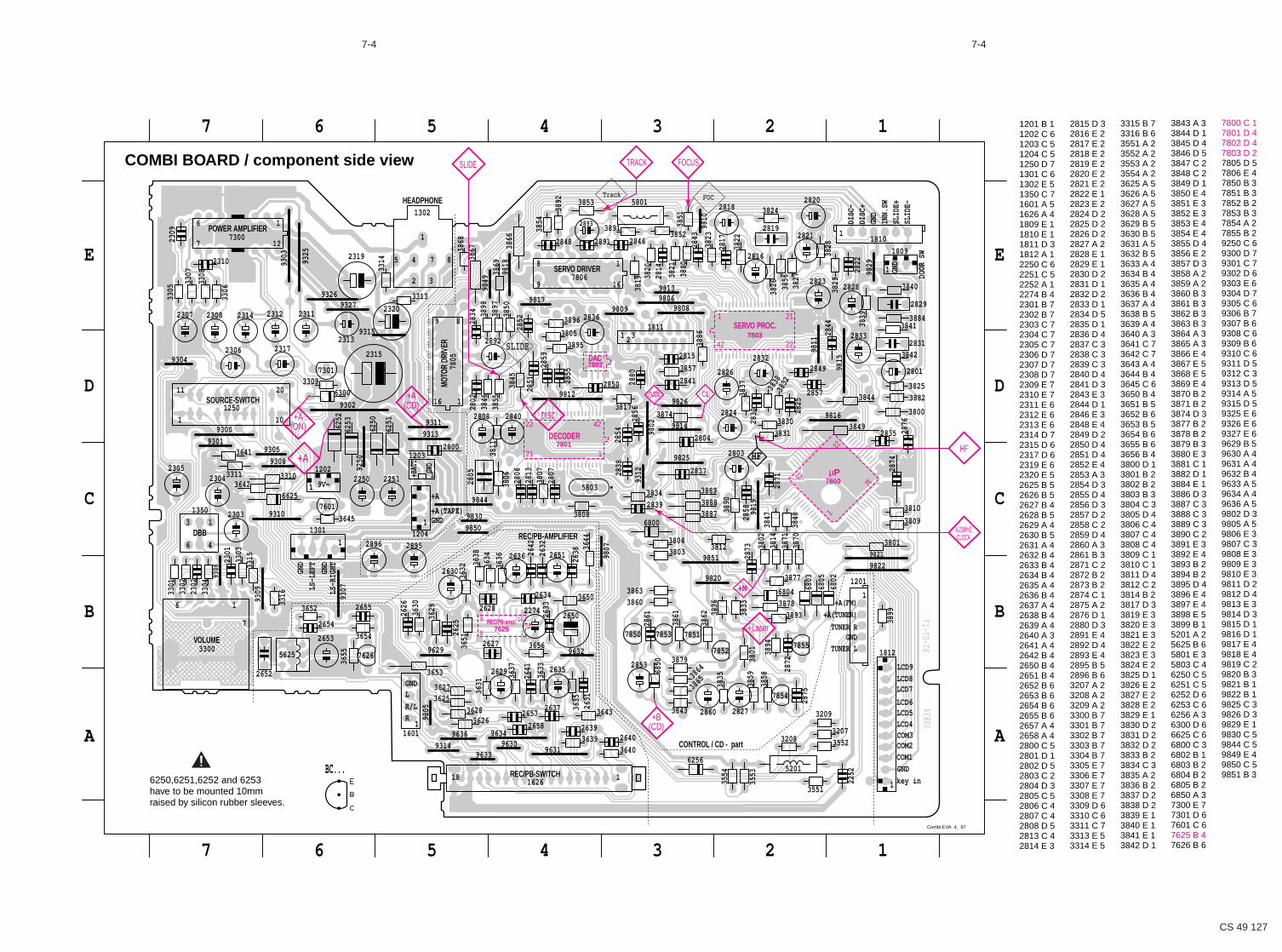
7-47-4
CS 49 127
33834
97-07-17
1234567
1234567
E
D
C
B
A
E
D
C
B
A
SERVO DRIVER
1
2
8
3
5
MOTO
R DR
IVER
HEADPHONE
4 7
11
SLID
E-SL
IDE+
INN.
SW
2821
2829
1810
1
3841
3844 3882
3884
GND
1809
2801
2831
3800
3825
3840
3842
2833
DOOR
SW
9821
9822
2835
2874
2876
3809
3810
3801
3849
1812
3899
COM2COM3LCD4LCD5LCD6
LCD7LCD8LCD9
key in
GNDCOM1
2818
2819
28203824
3823
38282817
3822
1
GND
DISC
+DI
SC-
FOC
9811
9815
9829
9808
3886
3832
3837 3838
3839
3829
3856
2832
2844
2849
2857
3826 3827
2822
2825
2826
2830
2816
28232828
3870
3871
2858 9819
HF
9820
9851
9825
9816
6803
6805
9814
3877
38873888
3889
3890
6802
3814
3812
3830
3831
3847
3848
3874
2873 38
02
2804
2824
2871
2803
2837
1
TUNER LGND
TUNER R
+A(TUNER)
+A(FM)
7851
7852
7854
7855
3859
3862
38786804
3894
38933833
3835
3836
3858
3209
355238
01
1201
2827
2853
2872
2875
32083207
2860
3554
3553
12252
3551
52016256
3891
5801
9810
3892
3880
Track
2893 3851
3853
2848
2814
3820
3852
3854
3821
2843
2880
16
1 32
2859
9826
98139817
9812
98069809
9802
7806
2850
3896
3819
3805
3857
3817
2841
1
2852
2856
3895
2855
2891
1811
2846
2836
2815
3834
6800
9312
9807
5803
3644
3803
3807
3808
380426
32
26382651
2805
2807 2838
2839
2854
3639
2658
3865
3864
7853
9631
9634
96323879
6850
7850
3863
3640
3643
3650
3656
3843
3860
3861
2640
2641
2650
2861
3633
3635
2274
2631
2633
2634
2635
2637
2639
1REC/PB-SWITCH
REC/PB-AMPLIFIER
CONTROL / CD - part
1626
1302
3866
3811
3868
2851
8
8
16
SLIDE2313
1
9849
3845
9
7805
9315
9327
9818
9302
9
3897
3898
3869
3867
3855
2892
3313
3314
3846
2315
2319
2320
2802
2808
2834 3850
1
GND
GND
+BAT
T
1
9250
93119313
98309850
9844
3634
3636
3638
6250
6251
3806
+A
+A(TAPE)28
0628
13
2840
3632
28952896
1203
120426
42
2800
2250 2251
2636
2630
2657
9314
1
L
76269629
96309633
9636
9805
2655
3654
3631
3637
3651
3653
36293630
R
3625
3626
3627
3628
2628
R/L
1601
2625
2627
2629
2626
GND
18
16
7300
9303
9325
7 12
20
101
9326
33096300
73019304
2310
3307
3308
2312
2317
3306
2311
1250
2307 2308 2314
2306
9305
9308
9V~
LS-R
IGHTGND
LS-L
EFT
GND
SOURCE-SWITCH
POWER AMPLIFIER
DBB4
13
1
9301
9307
9309
9310
3315
9306
13642
3645
6252
6253
66257601
9300
3304
3310
3316
3303
2303
3641
33111202
1301
1350
2301
2302
2304
5625
VOLUME
7
1
3655
2652
3300
3652
2653
2654
2309
3305
6
2305
3301
3302
6
1201 B 11202 C 61203 C 51204 C 51250 D 71301 C 61302 E 51350 C 71601 A 51626 A 41809 E 11810 E 11811 D 31812 A 12250 C 62251 C 52252 A 12274 B 42301 B 72302 B 72303 C 72304 C 72305 C 72306 D 72307 D 72308 D 72309 E 72310 E 72311 E 62312 E 62313 E 62314 D 72315 D 62317 D 62319 E 62320 E 52625 B 52626 B 52627 B 42628 B 52629 A 42630 B 52631 A 42632 B 42633 B 42634 B 42635 A 42636 B 42637 A 42638 B 42639 A 42640 A 32641 A 42642 B 42650 B 42651 B 42652 B 62653 B 62654 B 62655 B 62657 A 42658 A 42800 C 52801 D 12802 D 52803 C 22804 D 32805 C 52806 C 42807 C 42808 D 52813 C 42814 E 3
2815 D 32816 E 22817 E 22818 E 22819 E 22820 E 22821 E 22822 E 12823 E 22824 D 22825 D 22826 D 22827 A 22828 E 12829 E 12830 D 22831 D 12832 D 22833 D 12834 D 52835 D 12836 D 42837 C 32838 C 32839 C 32840 D 42841 D 32843 E 32844 D 12846 E 32848 E 42849 D 22850 D 42851 D 42852 E 42853 A 32854 D 32855 D 42856 D 32857 D 22858 C 22859 D 42860 A 32861 B 32871 C 22872 B 22873 B 22874 C 12875 A 22876 D 12880 D 32891 E 42892 D 42893 E 42895 B 52896 B 63207 A 23208 A 23209 A 23300 B 73301 B 73302 B 73303 B 73304 B 73305 E 73306 E 73307 E 73308 E 73309 D 63310 C 63311 C 73313 E 53314 E 5
3315 B 73316 B 63551 A 23552 A 23553 A 23554 A 23625 A 53626 A 53627 A 53628 A 53629 B 53630 B 53631 A 53632 B 53633 A 43634 B 43635 A 43636 B 43637 A 43638 B 53639 A 43640 A 33641 C 73642 C 73643 A 43644 B 43645 C 63650 B 43651 B 53652 B 63653 B 53654 B 63655 B 63656 B 43800 D 13801 B 23802 B 23803 B 33804 C 33805 D 43806 C 43807 C 43808 C 43809 C 13810 C 13811 D 43812 C 23814 B 23817 D 33819 E 33820 E 33821 E 33822 E 23823 E 33824 E 23825 D 13826 E 23827 E 23828 E 23829 E 13830 D 23831 D 23832 D 23833 B 23834 C 33835 A 23836 B 23837 D 23838 D 23839 E 13840 E 13841 E 13842 D 1
3843 A 33844 D 13845 D 43846 D 53847 C 23848 C 23849 D 13850 E 43851 E 33852 E 33853 E 43854 E 43855 D 43856 E 23857 D 33858 A 23859 A 23860 B 33861 B 33862 B 33863 B 33864 A 33865 A 33866 E 43867 E 53868 E 53869 E 43870 B 23871 B 23874 D 33877 B 23878 B 23879 B 33880 E 33881 C 13882 D 13884 E 13886 D 33887 C 33888 C 33889 C 33890 C 23891 E 33892 E 43893 B 23894 B 23895 D 43896 E 43897 E 43898 E 53899 B 15201 A 25625 B 65801 E 35803 C 46250 C 56251 C 56252 D 66253 C 66256 A 36300 D 66625 C 66800 C 36802 B 16803 B 26804 B 26805 B 26850 A 37300 E 77301 D 67601 C 67625 B 47626 B 6
7800 C 17801 D 47802 D 47803 D 27805 D 57806 E 47850 B 37851 B 37852 B 27853 B 37854 A 27855 B 29250 C 69300 D 79301 C 79302 D 69303 E 69304 D 79305 C 69306 B 79307 B 69308 C 69309 B 69310 C 69311 D 59312 C 39313 D 59314 A 59315 D 59325 E 69326 E 69327 E 69629 B 59630 A 49631 A 49632 B 49633 A 59634 A 49636 A 59802 D 39805 A 59806 E 39807 C 39808 E 39809 E 39810 E 39811 D 29812 D 49813 E 39814 D 39815 D 19816 D 19817 E 49818 E 49819 C 29820 B 39821 B 19822 B 19825 C 39826 D 39829 E 19830 C 59844 C 59849 E 49850 C 59851 B 3
COMBI BOARD / component side view
BC...6250,6251,6252 and 6253have to be mounted 10mmraised by silicon rubber sleeves.
Combi EVA .4, 97
!
7800
SERVO PROC.
DAC
µP
7803
7802
7801DECODER
7625
1234
1
23
1
18
9 16
14
5 8
42
21
1 21
22
42 22
REC/PB-ampl.
SLIDE TRACK FOCUS
HF
4.23MHZCLOCK
DISC
+A(CD)
+A(ON)
+B(CD)
+M
CLDATA
+A
+Laser
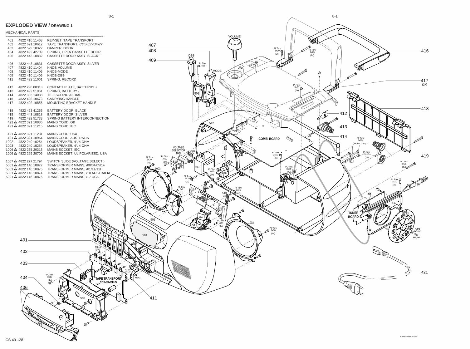
EVA-EV main, 071097
MODE
VOLTAGESELECTOR
COMBI BOARD
TAPE TRANSPORTCDS-83VBF-77
FRONT BOARD
DBB
VOLUME
TUNERBOARD
1007
5001
1006
1002
1003
501
Pl. Torx3x10(4x)
Pl. Torx2,6x10
M2x4(6x)
M2x3
M2,6x6
8x5x0,3
Pl. Torx3x10(4x)
Pl. Torx2x8(3x)
Pl. Torx3x10(4x)
Pl. Torx3x10(2x)
Pl. Torx3x16(2x)
Pl. Torx2x8(2x)
Pl. Torx3x10(2x)
Pl. Torx3x16(4x)
Pl. Torx3x25
Pl. Torx3x10(4x)
Pl. Torx3x25(2x)
Pl. Torx3x25(4x)
Pl. Torx3x10(3x)
Pl. Torx3x16(2x)
Pl. Torx3x25
(3x batt.comp.)
Pl. Torx3x30(2x)
Pl. Torx3x10(2x)
Pl. Torx3x25(2x)
401
402
403
404
406
411
407408
409
412
416
417(2x)
418
413
414
419
504
506
503
502
507
511
509
510
5132x
514
508
512
517
516
518
519
421
8-1 8-1
CS 49 128
EXPLODED VIEW / DRAWING 1
MECHANICAL PARTS–––––––––––––––––––––––––––––––––––––––––––––––––––––
401 4822 410 11403 KEY-SET, TAPE TRANSPORT402 4822 691 10612 TAPE TRANSPORT, CDS-83VBF-77403 4822 529 10322 DAMPER, DOOR404 4822 492 42709 SPRING, OPEN CASSETTE DOOR406 4822 443 10832 CASSETTE DOOR ASSY, BLACK
406 4822 443 10831 CASSETTE DOOR ASSY, SILVER407 4822 410 11404 KNOB-VOLUME408 4822 410 11406 KNOB-MODE409 4822 410 11405 KNOB-DBB411 4822 492 11061 SPRING, RECORD
412 4822 290 80313 CONTACT PLATE, BATTERRY +413 4822 492 51961 SPRING, BATTERY -414 4822 303 14038 TELESCOPIC AERIAL416 4822 498 10673 CARRYING HANDLE417 4822 402 10856 MOUNTING BRACKET HANDLE
418 4822 423 41255 BATTERY DOOR, BLACK418 4822 443 10818 BATTERY DOOR, SILVER419 4822 492 51733 SPRING BATTERY INTERCONNECTION421! 4822 321 10886 MAINS CORD, GB421! 4822 321 11215 MAINS CORD, IEC
421! 4822 321 11231 MAINS CORD, USA421! 4822 321 10954 MAINS CORD, AUSTRALIA
1002 4822 240 10254 LOUDSPEAKER, 4“, 4 OHM 1003 4822 240 10254 LOUDSPEAKER, 4“, 4 OHM 1006! 4822 265 20318 MAINS SOCKET, IEC1006! 4822 265 20706 MAINS SOCKET, UL POLARIZED, USA
1007! 4822 277 21794 SWITCH SLIDE (VOLTAGE SELECT.)5001! 4822 146 10877 TRANSFORMER MAINS, /00/04/05/145001! 4822 146 10875 TRANSFORMER MAINS, /01/11/11H5001! 4822 146 10874 TRANSFORMER MAINS, /10 AUSTRALIA5001! 4822 146 10876 TRANSFORMER MAINS, /17 USA

8-2
CS 49 129
EVA-EV top, 031097
CD DRIVECD94-V5-T1
DOOR SWITCH1807
Pl. Torx3x10(3x)
Pl. Torx2,6x10
(2x)
Pl. Torx2,6x10
(4x)
M2x6(2x)
426
427437
403
428
429
431
432
433
434(2x)
436(2x)
529
528
527
526
distinguishing markpos. 436
EXPLODED VIEW / DRAWING 2
MECHANICAL PARTS––––––––––––––––––––––––––––––––––––––––––––––––––––
403 4822 529 10322 DAMPER, DOOR426 4822 443 10833 CD DOOR, BLACK426 4822 443 10819 CD DOOR, SILVER427 4822 532 12798 CD CLAMP428 4822 535 60096 DAMPING DISC CD
429 4822 410 11506 KNOB EJECT CD DOOR, BLACK429 4822 410 11507 KNOB EJECT CD DOOR , SILVER431 4822 492 11058 SPRING, EJECT CD DOOR432 4822 402 10723 LEVER, EJECT CD DOOR433 4822 691 10654 CD-DRIVE, CD94-V5-T1 (Mabuchi motors)
434 4822 529 10386 RUBBER DAMPER CD DRIVE, REAR436 4822 529 10387 RUBBER DAMPER CD DRIVE, FRONT437 4822 492 71653 SPRING, OPEN CD DOOR

8-3
CS 49 130
4822 691 10612 TAPE TRANSPORT CDS-83VBF-7710 4822 528 70849 PINCH ROLLER ARM11 4822 528 70695 PINCH ROLLER ASSY74 4822 403 70968 EJECT HOOK
106 4822 358 31325 MAIN BELT107 4822 358 31124 SUB BELT
110 4822 278 90721 LEAF SWITCH, MOTOR ON/OFF111 4822 249 30218 REC/PB-HEAD, MS18R-AKONI112 4822 249 40306 ERASE HEAD, TDK6PA115 4822 361 21656 MOTOR, EG-530AD-9B116 4822 528 81497 MOTOR PULLEY
Only those parts of which a service code number is statedare normal service parts.
EXPLODED VIEW TAPE TRANSPORT
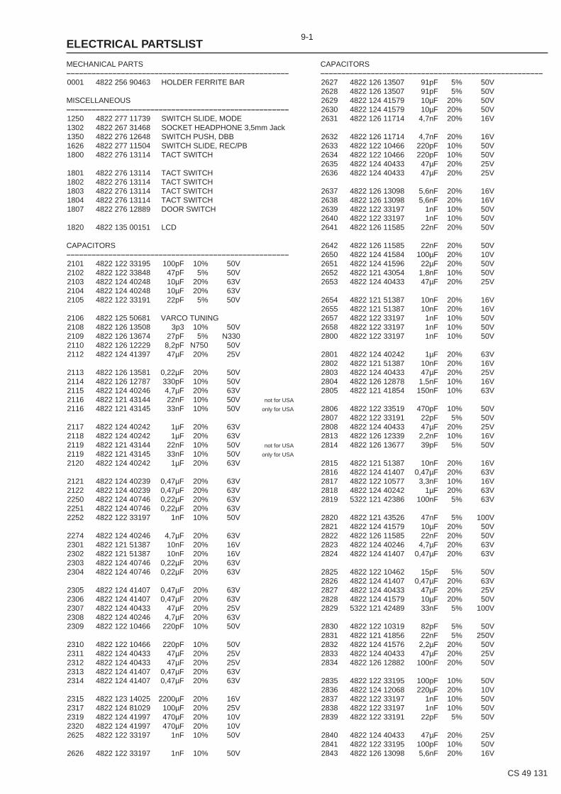
MECHANICAL PARTS–––––––––––––––––––––––––––––––––––––––––––––––––––––0001 4822 256 90463 HOLDER FERRITE BAR
MISCELLANEOUS–––––––––––––––––––––––––––––––––––––––––––––––––––––1250 4822 277 11739 SWITCH SLIDE, MODE1302 4822 267 31468 SOCKET HEADPHONE 3,5mm Jack1350 4822 276 12648 SWITCH PUSH, DBB1626 4822 277 11504 SWITCH SLIDE, REC/PB1800 4822 276 13114 TACT SWITCH
1801 4822 276 13114 TACT SWITCH1802 4822 276 13114 TACT SWITCH1803 4822 276 13114 TACT SWITCH1804 4822 276 13114 TACT SWITCH1807 4822 276 12889 DOOR SWITCH
1820 4822 135 00151 LCD
CAPACITORS–––––––––––––––––––––––––––––––––––––––––––––––––––––2101 4822 122 33195 100pF 10% 50V2102 4822 122 33848 47pF 5% 50V2103 4822 124 40248 10µF 20% 63V2104 4822 124 40248 10µF 20% 63V2105 4822 122 33191 22pF 5% 50V
2106 4822 125 50681 VARCO TUNING2108 4822 126 13508 3p3 10% 50V2109 4822 126 13674 27pF 5% N3302110 4822 126 12229 8,2pF N750 50V2112 4822 124 41397 47µF 20% 25V
2113 4822 126 13581 0,22µF 20% 50V2114 4822 126 12787 330pF 10% 50V2115 4822 124 40246 4,7µF 20% 63V2116 4822 121 43144 22nF 10% 50V not for USA
2116 4822 121 43145 33nF 10% 50V only for USA
2117 4822 124 40242 1µF 20% 63V2118 4822 124 40242 1µF 20% 63V2119 4822 121 43144 22nF 10% 50V not for USA
2119 4822 121 43145 33nF 10% 50V only for USA
2120 4822 124 40242 1µF 20% 63V
2121 4822 124 40239 0,47µF 20% 63V2122 4822 124 40239 0,47µF 20% 63V2250 4822 124 40746 0,22µF 20% 63V2251 4822 124 40746 0,22µF 20% 63V2252 4822 122 33197 1nF 10% 50V
2274 4822 124 40246 4,7µF 20% 63V2301 4822 121 51387 10nF 20% 16V2302 4822 121 51387 10nF 20% 16V2303 4822 124 40746 0,22µF 20% 63V2304 4822 124 40746 0,22µF 20% 63V
2305 4822 124 41407 0,47µF 20% 63V2306 4822 124 41407 0,47µF 20% 63V2307 4822 124 40433 47µF 20% 25V2308 4822 124 40246 4,7µF 20% 63V2309 4822 122 10466 220pF 10% 50V
2310 4822 122 10466 220pF 10% 50V2311 4822 124 40433 47µF 20% 25V2312 4822 124 40433 47µF 20% 25V2313 4822 124 41407 0,47µF 20% 63V2314 4822 124 41407 0,47µF 20% 63V
2315 4822 123 14025 2200µF 20% 16V2317 4822 124 81029 100µF 20% 25V2319 4822 124 41997 470µF 20% 10V2320 4822 124 41997 470µF 20% 10V2625 4822 122 33197 1nF 10% 50V
2626 4822 122 33197 1nF 10% 50V
CAPACITORS–––––––––––––––––––––––––––––––––––––––––––––––––––––2627 4822 126 13507 91pF 5% 50V2628 4822 126 13507 91pF 5% 50V2629 4822 124 41579 10µF 20% 50V2630 4822 124 41579 10µF 20% 50V2631 4822 126 11714 4,7nF 20% 16V
2632 4822 126 11714 4,7nF 20% 16V2633 4822 122 10466 220pF 10% 50V2634 4822 122 10466 220pF 10% 50V2635 4822 124 40433 47µF 20% 25V2636 4822 124 40433 47µF 20% 25V
2637 4822 126 13098 5,6nF 20% 16V2638 4822 126 13098 5,6nF 20% 16V2639 4822 122 33197 1nF 10% 50V2640 4822 122 33197 1nF 10% 50V2641 4822 126 11585 22nF 20% 50V
2642 4822 126 11585 22nF 20% 50V2650 4822 124 41584 100µF 20% 10V2651 4822 124 41596 22µF 20% 50V2652 4822 121 43054 1,8nF 10% 50V2653 4822 124 40433 47µF 20% 25V
2654 4822 121 51387 10nF 20% 16V2655 4822 121 51387 10nF 20% 16V2657 4822 122 33197 1nF 10% 50V2658 4822 122 33197 1nF 10% 50V2800 4822 122 33197 1nF 10% 50V
2801 4822 124 40242 1µF 20% 63V2802 4822 121 51387 10nF 20% 16V2803 4822 124 40433 47µF 20% 25V2804 4822 126 12878 1,5nF 10% 16V2805 4822 121 41854 150nF 10% 63V
2806 4822 122 33519 470pF 10% 50V2807 4822 122 33191 22pF 5% 50V2808 4822 124 40433 47µF 20% 25V2813 4822 126 12339 2,2nF 10% 16V2814 4822 126 13677 39pF 5% 50V
2815 4822 121 51387 10nF 20% 16V2816 4822 124 41407 0,47µF 20% 63V2817 4822 122 10577 3,3nF 10% 16V2818 4822 124 40242 1µF 20% 63V2819 5322 121 42386 100nF 5% 63V
2820 4822 121 43526 47nF 5% 100V2821 4822 124 41579 10µF 20% 50V2822 4822 126 11585 22nF 20% 50V2823 4822 124 40246 4,7µF 20% 63V2824 4822 124 41407 0,47µF 20% 63V
2825 4822 122 10462 15pF 5% 50V2826 4822 124 41407 0,47µF 20% 63V2827 4822 124 40433 47µF 20% 25V2828 4822 124 41579 10µF 20% 50V2829 5322 121 42489 33nF 5% 100V
2830 4822 122 10319 82pF 5% 50V2831 4822 121 41856 22nF 5% 250V2832 4822 124 41576 2,2µF 20% 50V2833 4822 124 40433 47µF 20% 25V2834 4822 126 12882 100nF 20% 50V
2835 4822 122 33195 100pF 10% 50V2836 4822 124 12068 220µF 20% 10V2837 4822 122 33197 1nF 10% 50V2838 4822 122 33197 1nF 10% 50V2839 4822 122 33191 22pF 5% 50V
2840 4822 124 40433 47µF 20% 25V2841 4822 122 33195 100pF 10% 50V2843 4822 126 13098 5,6nF 20% 16V
9-1
CS 49 131
ELECTRICAL PARTSLIST

CAPACITORS–––––––––––––––––––––––––––––––––––––––––––––––––––––2844 4822 122 33195 100pF 10% 50V2846 4822 122 33197 1nF 10% 50V2848 4822 122 33197 1nF 10% 50V2850 4822 126 12882 100nF 20% 50V2851 4822 126 11714 4,7nF 20%
2852 4822 126 11714 4,7nF 20%2854 4822 122 33195 100pF 10% 50V2855 4822 122 33195 100pF 10% 50V2856 4822 122 33195 100pF 10% 50V2859 4822 121 51387 10nF 20% 16V
2860 4822 124 40433 47µF 20% 25V2871 4822 126 11714 4,7nF 20%2873 4822 126 12882 100nF 20% 50V2874 4822 122 33197 1nF 10% 50V2880 4822 122 33197 1nF 10% 50V
2891 4822 121 51387 10nF 20% 16V2892 4822 124 40433 47µF 20% 25V2893 4822 124 40433 47µF 20% 25V2895 4822 124 40242 1µF 20% 63V2896 4822 124 40242 1µF 20% 63V
RESISTORS–––––––––––––––––––––––––––––––––––––––––––––––––––––3101 4822 100 20167 50kΩ TRIMPOT. LIN.3102 4822 116 52297 68kΩ 5% 0,5W3104 4822 116 52256 2,2kΩ 5% 0,16W3106 4822 116 52231 820Ω 5% 0,5W3107 4822 116 52191 33Ω 5% 0,5W
3113 4822 116 52234 100kΩ 5% 0,5W3114 4822 116 52234 100kΩ 5% 0,5W3207 4822 116 52191 33Ω 5% 0,5W3208 4822 116 52191 33Ω 5% 0,5W3209 4822 116 52234 100kΩ 5% 0,5W
3300 4822 101 11826 2x50kΩ LIN., VOLUME POTMETER3301 4822 116 52256 2,2kΩ 5% 0,16W3302 4822 116 52256 2,2kΩ 5% 0,16W3303 4822 116 52243 1,5kΩ 5% 0,16W3304 4822 116 52243 1,5kΩ 5% 0,16W
3305 4822 116 83883 470Ω 5% 0,16W3306 4822 116 83883 470Ω 5% 0,16W3307 4822 116 52219 330Ω 5% 0,5W3308 4822 116 52219 330Ω 5% 0,5W3309 4822 116 52238 12kΩ 5% 0,5W
3310 4822 116 52249 1,8kΩ 5% 0,16W3311 4822 116 52249 1,8kΩ 5% 0,16W3313 4822 116 52206 120Ω 5% 0,5W3314 4822 116 52206 120Ω 5% 0,5W3315 4822 116 83864 10kΩ 5% 0,5W
3316 4822 116 83864 10kΩ 5% 0,5W3551 4822 116 52256 2,2kΩ 5% 0,16W3552 4822 116 52256 2,2kΩ 5% 0,16W3553 4822 116 83961 6,8kΩ 5% 0,16W3554 4822 116 83961 6,8kΩ 5% 0,16W
3625 4822 116 83883 470Ω 5% 0,16W3626 4822 116 83883 470Ω 5% 0,16W3627 4822 116 52264 27kΩ 5% 0,5W3628 4822 116 52264 27kΩ 5% 0,5W3629 4822 116 83883 470Ω 5% 0,16W
3630 4822 116 83883 470Ω 5% 0,16W3631 4822 116 52219 330Ω 5% 0,5W3632 4822 116 52219 330Ω 5% 0,5W3633 4822 116 52272 330kΩ 5% 0,5W3634 4822 116 52272 330kΩ 5% 0,5W
3635 4822 116 83961 6,8kΩ 5% 0,16W3636 4822 116 83961 6,8kΩ 5% 0,16W
RESISTORS–––––––––––––––––––––––––––––––––––––––––––––––––––––3637 4822 116 52264 27kΩ 5% 0,5W3638 4822 116 52264 27kΩ 5% 0,5W3639 4822 116 83864 10kΩ 5% 0,5W3640 4822 116 83864 10kΩ 5% 0,5W3641 4822 116 52228 680Ω 5% 0,5W
3642 4822 116 52228 680Ω 5% 0,5W3643 4822 116 52175 100Ω 5% 0,5W3644 4822 116 52175 100Ω 5% 0,5W3645 4822 050 11002 1kΩ 5% 0,2W3650 4822 116 52213 180Ω 5% 0,5W
3651 4822 116 52272 330kΩ 5% 0,5W3652 4822 116 83961 6,8kΩ 5% 0,16W3653 4822 116 52213 180Ω 5% 0,5W3654 4822 116 83868 150Ω 5% 0,5W3655 4822 116 52184 18Ω 5% 0,5W
3656 4822 111 30893 4,7MΩ 5% 0,2W3800 4822 116 52176 10Ω 5% 0,5W3801 4822 050 24708 4,7Ω 1% 0,6W3802 4822 116 52175 100Ω 5% 0,5W3803 4822 116 81154 2,2Ω 5% 0,5W
3804 4822 116 83868 150Ω 5% 0,5W3805 4822 116 52175 100Ω 5% 0,5W3806 4822 116 52256 2,2kΩ 5% 0,16W3807 4822 116 52271 33kΩ 5% 0,16W3808 4822 116 52263 2,7kΩ 5% 0,5W
3809 4822 116 52276 3,9kΩ 5% 0,5W3810 4822 050 11002 1kΩ 5% 0,2W3811 4822 111 30893 4,7MΩ 5% 0,2W3812 4822 116 52257 22kΩ 5% 0,5W3814 4822 116 52257 22kΩ 5% 0,5W
3817 4822 116 52234 100kΩ 5% 0,5W3819 4822 117 11825 1,5MΩ 5% 0,4W3820 4822 116 52252 180kΩ 5% 0,5W3821 4822 116 52243 1,5kΩ 5% 0,16W3822 4822 116 52264 27kΩ 5% 0,5W
3823 4822 116 52234 100kΩ 5% 0,5W3824 4822 116 83868 150Ω 5% 0,5W3825 4822 116 83883 470Ω 5% 0,16W3826 4822 116 83961 6,8kΩ 5% 0,16W3827 4822 116 52243 1,5kΩ 5% 0,16W
3828 4822 116 52238 12kΩ 5% 0,5W3829 4822 116 52271 33kΩ 5% 0,16W3830 4822 116 52244 15kΩ 5% 0,5W3831 4822 116 52251 18kΩ 5% 0,5W3832 4822 116 52222 390Ω 5% 0,16W
3833 4822 116 52264 27kΩ 5% 0,5W3834 4822 116 83872 220Ω 5% 0,5W3835 4822 116 52184 18Ω 5% 0,5W3836 4822 050 11002 1kΩ 5% 0,2W3837 4822 111 30893 4,7MΩ 5% 0,2W
3838 4822 116 52234 100kΩ 5% 0,5W3839 4822 116 52235 1MΩ 5% 0,5W3840 4822 050 11002 1kΩ 5% 0,2W3841 4822 116 52298 680kΩ 5% 0,5W3842 4822 116 52297 68kΩ 5% 0,5W
3843 4822 116 52222 390Ω 5% 0,16W3844 4822 116 52291 56kΩ 5% 0,5W3845 4822 116 52239 120kΩ 5% 0,5W3846 4822 050 11002 1kΩ 5% 0,2W3847 4822 116 52257 22kΩ 5% 0,5W
3849 4822 116 83872 220Ω 5% 0,5W3850 4822 116 52283 4,7kΩ 5% 0,5W3851 4822 116 52244 15kΩ 5% 0,5W3852 4822 116 83883 470Ω 5% 0,16W
9-2
CS 49 132
ELECTRICAL PARTSLIST

RESISTORS–––––––––––––––––––––––––––––––––––––––––––––––––––––3853 4822 116 52244 15kΩ 5% 0,5W3854 4822 116 52243 1,5kΩ 5% 0,16W3855 4822 116 52271 33kΩ 5% 0,16W3856 4822 116 52303 8,2kΩ 5% 0,5W3857 4822 116 52269 3,3kΩ 5% 0,5W
3858 4822 116 80176 1Ω 5% 0,5W3859 4822 116 83864 10kΩ 5% 0,5W3860 4822 050 18208 8,2Ω 1% 0,4W3861 4822 050 18208 8,2Ω 1% 0,4W3862 4822 116 52269 3,3kΩ 5% 0,5W
3863 4822 116 52219 330Ω 5% 0,5W3864 4822 116 52256 2,2kΩ 5% 0,16W3865 4822 116 52256 2,2kΩ 5% 0,16W3866! 4822 052 10828 8,2Ω 5% 0,3W3867! 4822 052 10338 3,3Ω NFR25
3868 4822 116 80176 1Ω 5% 0,5W3869 4822 116 83883 470Ω 5% 0,16W3870 4822 116 52257 22kΩ 5% 0,5W3871 4822 050 11002 1kΩ 5% 0,2W3872 4822 116 83882 39kΩ 5% 0,5W
3873 4822 116 52257 22kΩ 5% 0,5W3874 4822 116 83872 220Ω 5% 0,5W3875 4822 116 52256 2,2kΩ 5% 0,16W3876 4822 116 52283 4,7kΩ 5% 0,5W3877 4822 116 52244 15kΩ 5% 0,5W
3878 4822 116 52228 680Ω 5% 0,5W3880 4822 116 52207 1,2kΩ 5% 0,5W3881 4822 116 52257 22kΩ 5% 0,5W3882 4822 116 83864 10kΩ 5% 0,5W3884 4822 116 83882 39kΩ 5% 0,5W
3886 4822 116 52235 1MΩ 5% 0,5W3887 4822 116 83872 220Ω 5% 0,5W3888 4822 116 83883 470Ω 5% 0,16W3889 4822 116 83883 470Ω 5% 0,16W3890 4822 116 83864 10kΩ 5% 0,5W
3891 4822 116 83883 470Ω 5% 0,16W3892 4822 116 83883 470Ω 5% 0,16W3893 4822 116 52271 33kΩ 5% 0,16W3894 4822 116 83883 470Ω 5% 0,16W3895 4822 116 52276 3,9kΩ 5% 0,5W
3896 4822 116 52276 3,9kΩ 5% 0,5W3897 4822 116 83883 470Ω 5% 0,16W3898 4822 116 83883 470Ω 5% 0,16W3899 4822 050 11002 1kΩ 5% 0,2W
COILS–––––––––––––––––––––––––––––––––––––––––––––––––––––1102 4822 526 10176 FERRITE BAR 5X13X55MM5101 4822 157 70513 RF COIL 3,5 TURNS5102 4822 157 70731 COIL, FERR. ANT. (w/o FERRITE BAR)5104 4822 156 30947 RF COIL 1,5 TURNS5105 4822 157 71145 COIL VAR., MW-OSC.
5106 4822 157 70499 AM-IF FILTER, 468kHz5107 4822 242 81154 FILTER KIT, FM-IF5108 4822 156 11146 AM-IF FILTER, 468kHz5201 4822 526 10494 FERRITE BEAD5625 4822 157 10371 BIAS OSC. COIL VAR. 100kHz
5801 4822 526 10494 FERRITE BEAD5803 4822 242 73557 CERAMIC RES. 8,46MHz
DIODES–––––––––––––––––––––––––––––––––––––––––––––––––––––6101 4822 130 30621 1N41486102 4822 130 30621 1N41486250! 4822 130 31878 1N4003G6251! 4822 130 31878 1N4003G
DIODES–––––––––––––––––––––––––––––––––––––––––––––––––––––6252! 4822 130 31878 1N4003G6253! 4822 130 31878 1N4003G6256 4822 130 30621 1N41486300 4822 130 30621 1N41486625 4822 130 34167 BZX79-B6V2
6800 4822 130 31881 BZX79-B3V06803 4822 130 30621 1N41486804 4822 130 30621 1N41486805 4822 130 31981 BZX79-C3V96850 4822 130 31881 BZX79-B3V0
TRANSISTORS–––––––––––––––––––––––––––––––––––––––––––––––––––––7102 4822 130 44196 BC548C7301 4822 130 40937 BC548B7601 4822 130 44196 BC548C7626 4822 130 40937 BC548B7850 4822 130 41327 BC327-40
7851 4822 130 44197 BC558B7852 4822 130 41327 BC327-407853 4822 130 44196 BC548C7854 5322 130 60068 BC558C7855 4822 130 44196 BC548C
INTEGRATED CIRCUITS–––––––––––––––––––––––––––––––––––––––––––––––––––––7101 © 4822 209 32746 TEA5711T/N2, RADIO IC7300 4822 209 31544 TA8227P, POWER AMPLIFIER IC7625 © 4822 209 32918 AN7318S, Rec/Pb-AMPLIFIER IC7800 © 4822 209 15932 TMP47C422F-AZ1010.1, µ-PROC.7801 © 4822 209 15952 M65824FP, SIGNAL PROCESSOR IC
7802 © 4822 209 32196 TDA1311AT/N2, DAC7803 © 4822 209 90496 M62475FP, SERVO PROCESSOR IC7805 4822 209 32852 TDA7073A/N2, MOTOR DRIVER7806 4822 209 32852 TDA7073A/N2, SERVO DRIVER
9-3
CS 49 133
ELECTRICAL PARTSLIST