Aspects of pre/post processing a detailed wing FEM with …... · FEMAP Symposium 2017 Aspects of...
46
Aspects of pre/post processing a detailed wing FEM with Femap FEMAP SYMPOSIUM January 17, Vero Beach, FL Eric Gustafson, Senior Stress Analyst, SDA – [email protected] Alex Skavdahl, Stress Analyst, SDA – [email protected]
Transcript of Aspects of pre/post processing a detailed wing FEM with …... · FEMAP Symposium 2017 Aspects of...

Aspects of pre/post processing a detailed wing FEM with FemapFEMAP SYMPOSIUMJanuary 17, Vero Beach, FL
Eric Gustafson, Senior Stress Analyst, SDA – [email protected]
Alex Skavdahl, Stress Analyst, SDA – [email protected]

FEMAP Symposium 2017
Aspects of pre/post processing a detailed wing FEM with Femap
geometry preparation
meshing practices
Nastran’s advanced non-linear solver
the use of built-in tools and development of new ones to interpret results

FEMAP Symposium 2017
What are some typical problems faced when generating a wing FEM (or any FEM)?
Highly detailed geometry from designers is not amenable to direct meshing
Choices of meshing approach
A great many unique properties to be assigned
Handling loads
How to interpret vast amounts of data quickly for effective decision-making

FEMAP Symposium 2017
Rapid wing model pre-processing
LE spar0.050/ 2024-T42
Splice plate (each side)0.040/ 2024-T3
Information captured from NX models via Teamcenter (A Siemens product)
- Geometry model- Midsurfaces built and
assembled from original CAD- Material and dimension data
- Documented for each major primary structure component
- < 1 day to gather all necessary information to begin FEM pre-processing
- 1 engineer created properties for all unique zones and created a surface ID vs property ID list

FEMAP Symposium 2017
This build is far too complicated for auto-midsurfacing
Simple part CAD- Automatic midsurfacing is useful
for solid monolithic geometry with constant thickness
Aerospace CAD- Many more solids than what is
needed by analyst- The task of meshing must be
bounded with some early geometry preparation
- Early decisions on modeling approach for features

FEMAP Symposium 2017
Surface preparation and mesh process
1. Raw geometry from design CAD imported and organized into layers
2. For each surface1. Geometry Midsurface
Single3. All surfaces intersected and
combined with GeometrySurface NonManifold Add
4. Surfaces protruding OML are eliminated
5. Features are imprinted and then cut1. E.g. Access, routing, and
lightening holes, mouse holes, rib stiffeners
Surface 1 Surface 2
Surface 1 Surface 2
Two adjacent surfaces with two overlapping curves will lead to coincident nodes
If the two adjacent surfaces are part of a NonManifold solid, there will be no overlapping curves and thus no coincident nodes
FEMAP Symposium 2017
Surface prep and mesh process

FEMAP Symposium 2017
Surface prep and mesh process

FEMAP Symposium 2017
Surface prep and mesh process
Cut with fwdspar web
Cut with top skin OML
Cut with lower skin OML
Cut with aft spar web
Geometry Surface NonManifold Addoperation then performed to merge the surfaces onto the same solid. Surface ID is tracked in Excel file for property assignment.
Extraneous surface areas deleted

FEMAP Symposium 2017
Organization is key
Layer 3: Spanwise
Layer 4: Lower skin
Layer 2: Ribs
Layer 1: Upper skin
We prefer layers AND groups, the former for quick access to entities representing internal structure, and the latter for creating custom run decks.

FEMAP Symposium 2017
Rapid wing model pre-processing
Surface Object Properties API Tool
PurposeRapidly assign property IDs to surfaces.
InputList of surface ID vs property ID.
OutputAssigns property ID to surface ID. Also reads size, type, layer, CG location, property ID information.
FEMAP Symposium 2017
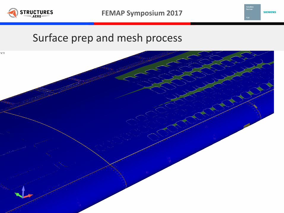
Rapid Model Generation
719 surfaces part of nonmanifoldgeometry edges curves are shared
between adjacent surfaces 2 man-weeks to process entire wing 212k elements
Element count driven by having 4 thru stringer height
Mostly 2D plate elements All mesh linked to geometry,
eliminates costly manual mesh update operations
Applying properties was trivial and done programmatically
Final set of surfaces
FEMAP Symposium 2017
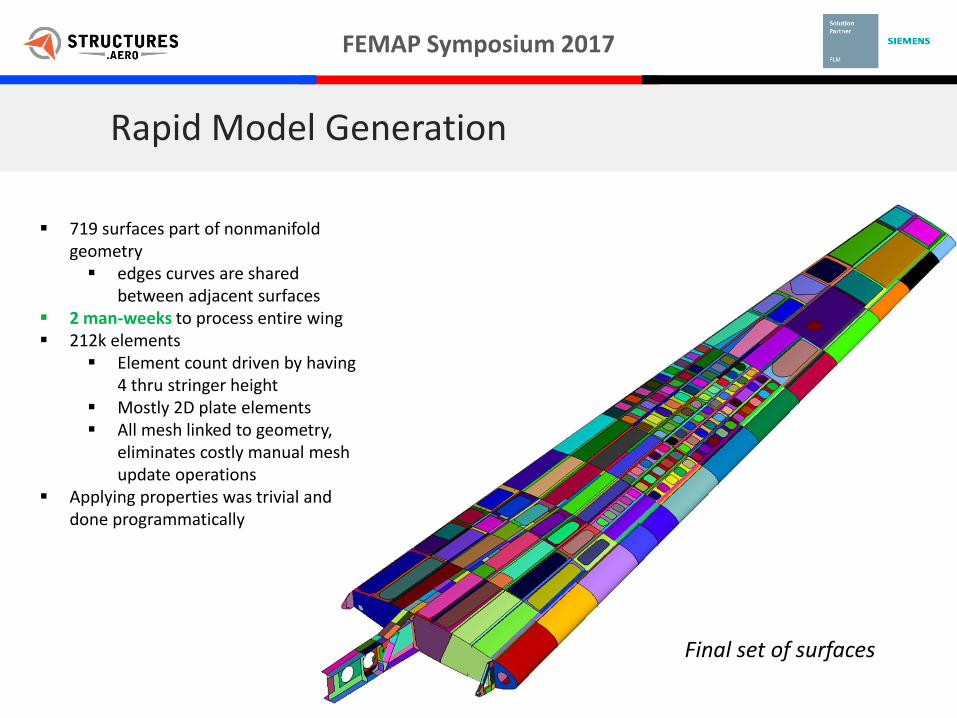
Rapid Model Generation
Final set of surfaces(upper skin removed)
719 surfaces part of nonmanifoldgeometry edges curves are shared
between adjacent surfaces 2 man-weeks to process entire wing 212k elements
Element count driven by having 4 thru stringer height
Mostly 2D plate elements All mesh linked to geometry,
eliminates costly manual mesh update operations
Applying properties was trivial and done programmatically

FEMAP Symposium 2017
Rapid Model Generation
Final mesh (no element edges shown)
719 surfaces part of nonmanifoldgeometry edges curves are shared
between adjacent surfaces 2 man-weeks to process entire wing 212k elements
Element count driven by having 4 thru stringer height
Mostly 2D plate elements All mesh linked to geometry,
eliminates costly manual mesh update operations
Applying properties was trivial and done programmatically

FEMAP Symposium 2017
Rapid Model Generation
Final mesh (detail)

FEMAP Symposium 2017
Rapid Model Generation
Final mesh (no upper skin)

FEMAP Symposium 2017
Boundary Conditions
Originally constrained using CBUSH elements @ root connections
Over represented inboard stiffness – poor correlation
Connected wing to portion of fuselage in loads FEM
Better representation of inboard stiffness – better correlation
Wing connected using File -> Merge command

FEMAP Symposium 2017
Merging Two FEMAP Models
File -> Merge is a useful tool for combining 2 separate FEMAP windows

FEMAP Symposium 2017
Fuel Pressure Loads
Needed to spread fuel pressure to various bays shown below
Typically a job for Femap’s Data Surface tool
BUT, no easy way to connect bays to elements
A custom API was developed taking advantage of still ASSOCIATED mesh / geometry
Tabulated Fuel Bay, Pressure, and
Surfaces
Custom FEMAP / Excel API to spread Pressure loads to
elements on surfaces
FEMAP geometric surfaces mapped to their corresponding
fuel bays

FEMAP Symposium 2017
Fuel Pressure Loads – Load Spreading Interface
Fuel BayPressure to Apply
FEMAP Surface IDs
Coordinate SystemInitial Pressure
Delta Pressure
Pseudo-Code:• Create a Load Set• For each Fuel Bay
• Create Load Definition• Assign load parameters
• Coordinate System• Pressure value• Equation
• Apply load to elements on selected surfaces
o ~1hr to map surfaces to bayso 1 time process
o <1 day to Run all cases

FEMAP Symposium 2017
Nonlinear Solution Approach - Motivation
• Why run NL?• Linear cannot capture proper
internal loading for ribs (Brazier effect)
• Want to verify behavior of structure up to ultimate is stable analytically and by comparison to test
• If any instabilities encountered, can show them to match predictions, be absorbable, or critical. Can gain insight into where and why they occurred.
• Can match strain predictions for cert and/or determine reserve strength

FEMAP Symposium 2017
Nonlinear Solution Approach - Types
• Implicit vs Explicit• All solutions undertaken were IMPLICIT as this is a static event with a slowly loaded structure• Explicit is better for dynamic events but has restrictions
• Time step requirements would require an inordinate amount of run time. • No pcomps• Interesting feature unexplored is implicit/explicit switching
• 106 vs 601• Adv NX Nastran based on ADINA code, is complementary to regular NX Nastran• 601 solver has more robust solution methods for getting through much more severe behavior
such as large strains (>10%), contact, post-buckling, element birth/death, etc.
Nastran SOL Femap “Analysis Type” Exec
106 10..Nonlinear Static 106
129 12..Nonlinear Transient Response 129
601 22..Advanced Nonlinear Static 601,106
601 23..Advanced Nonlinear Transient 601,129
701 24..Advanced Nonlinear Explicit 701

FEMAP Symposium 2017
Nonlinear Solution Approach - Convergence
Highly NL solutions can be plagued with convergence issues.
Lack of convergence arises when externally applied forces are not balanced by nodal forces within the convergence tolerances.
This can stem from the solution “getting ahead of itself”. Most often occurs as a result of large jumps in stiffness, such as when a skin or stringer component buckles. User may wish to use smaller loading increments, or have the solution automatically decrease magnitude of load step.

FEMAP Symposium 2017
NL Solution Approach –SOL 601 Parameters
PARAM,LGDISP,1• Enabled on the NASTRAN Bulk Data Options analysis dialog• For large displacements (geometric NL) effects and resulting
follower forces• FORCE and MOMENT cannot be follower forces (use FORCE1
or FORCE2 for point forces or alternatively, PLOAD pressure cards)
NXSTRAT “strategy parameters”• This card is unique to the advanced solver, and it’s
functionality is similar to the NLPARM card with 106.
Matrix Stabilization (MSTAB)• Scales diagonal stiffness terms to prevent pivot ratio problems.
Acts as if weak springs were attached to all DOF, but has no
detrimental effect on solution.
Load change with deformation (LOADOPT)• Pressure/ distributed loading is deformation dependent. • Applicable when LGDISP = 1.

FEMAP Symposium 2017
NL Solution Approach - Iteration and Convergence Parameters
Auto increment (AUTO)• 1..On = Automatic time stepping (ATS) enabled.
If no convergence for user-defined time step, program automatically subdivides time step until convergence attained.
• Time is analogous to load level
Continue if Non-Positive Definite (NPOSIT)• If diagonal element in stiffness matrix is 0 or
negative (indicating non-invertible), program will assign large value to that element (as if a stiff spring was affixed to the DOF it represents) and continue execution.
Max iterations/ step (MAXITE)• Sets maximum number of iterations to be used
per time step
Line search (LSEARCH)• Can assist convergence of first few iterations of a
time step when current displacements are far from the converged solution.
Low speed dynamics (ATSLOWS)• Brings mass and damping effects into the
otherwise static analysis. Allows for solutions with rigid-body modes and local snap-through or buckling instabilities.
Remaining options left to defaults

FEMAP Symposium 2017
NL Solution Approach - Verifying accuracy of solution
• Accuracy indicator history printed to solution F06 file
• Want magnitude of convergence-assisting effects to be low relative to external forces acting on the model
======================================================================================
S O L U T I O N A C C U R A C Y I N D I C A T O R S
FOR LOW SPEED DYNAMICS, CONTACT DAMPING, SHELL DRILLING AND STIFFNESS STABILIZATION
--------------------------------------------------------------------------------------
EXTERNAL DRILLING DAMPING INERTIA CONTACT STIFFNESS
FORCES FORCES FORCES FORCES DAMP.FORCES STABIL.
--------------------------------------------------------------------------------------
3.711E+02 2.144E-03 1.480E+00 1.422E+00 -- 8.323E-02
--------------------------------------------------------------------------------------
% of ext.forces 0.00 0.40 0.38 -- 0.02
======================================================================================

FEMAP Symposium 2017
Quick Demonstration – Navigating Models
Since internal structure can be obscured, any number of visibility settings (layers, groups, property enabling/disabling) can be used to expose necessary model parts
We tended to use the cross section. You can use the alt+scroll wheel when this is enabled to quick translate the cutting plane in the normal direction
Since this project was started, Draw/Erase has been added as a new feature in Femap v11.3

FEMAP Symposium 2017
Running a large amount of load cases
Successfully ran 43 load cases in roughly 1 week Load cases correspond directly to FAR certification Average run time: ~6 hrs on Intel Core i7 32GB RAM custom built workstation > 7days computer run time for all cases
NX Nastran Advanced nonlinear With parallel processing feature, simply set number of CPUs to use in the
Femap analysis setup dialog for solution options Most beneficial running 4-8 processors (disable HT for best performance is the
official Siemens recommendation)
Memory (NXNA_MEMORY) Avoid over-allocating RAM so that O/S has room for file I/O
No more than 80%-90% of your physical RAM Siemens normally recommends no more than 50%
32 GB is the norm at SDA, some machines 64 GB
All about book keeping (and time) Figuring out what worked, what did not, and WHY Figuring out options to push for convergence

FEMAP Symposium 2017
Post-processing vast NL results
General Process:• Envelope all results
Gives look at most critical conditions
Shows a good starting place• FEMAP’s PostProcessing Toolbox is a
great tool for visualizing results• Criteria options allow for visualization
within a user specified range• QUICKLY look through results, isolate
possible problem areas
FEMAP Symposium 2017
Post-processing vast NL results
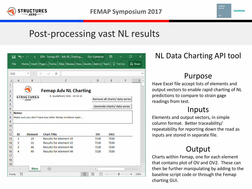
NL Data Charting API tool
PurposeHave Excel file accept lists of elements and output vectors to enable rapid charting of NL predictions to compare to strain gage readings from test.
InputsElements and output vectors, in simple column format. Better traceability/ repeatability for reporting down the road as inputs are stored in separate file.
OutputCharts within Femap, one for each element that contains plot of OV and OV2. These can then be further manipulating by adding to the baseline script code or through the Femapcharting GUI.

FEMAP Symposium 2017
Post-processing vast NL results
46
49
22
19
Script written with simple FEM first Top and bottom nonlinear strains successfully charted for all requested elements WITHOUT manual entry
OV 7130OV 7530

FEMAP Symposium 2017
Post-processing vast NL results
Script written directly in Excel
Pseudocode• Connect to Femap• For each row (each element)
• Create chart• Create data series for OV• Create data series for OV2• Add title to chart• Add data series to chart

FEMAP Symposium 2017
Example

FEMAP Symposium 2017
FEMAP has many great tools and features, but 2 limitations resulted in custom built tools
1. SOL 601 does not output any inter-laminar information
2. No quick way to check against an allowable that varies with span
Custom user APIs were written to calculate and summarize the required information using available output
Post-processing vast NL results – Custom Built Tools
Span
Allo
wab
le

FEMAP Symposium 2017
Post-processing vast NL results – Custom Built Tools
Advanced Non-Linear does not output inter-laminar shear for a composite or multilayer element, but we still need a way to determine the interlaminar Failure Index for bonded structure
The only TRANSVERSE information we have from Advanced Nonlinear is transverse stress per ply
Inter-laminar Shear is calculated using
𝑉 ∗𝑄
𝐼 ∗𝑡
Custom API written to calculate and create output for all laminate bonded structure for each load case

FEMAP Symposium 2017
General Process:
Use transverse shear STRESS output ( τxz / τyz ) for each ply in a laminate to calculate the transverse shear FORCE (Vxz / Vyz) for an element
Use the calculated shear force to calculated the interlaminate shear stresses using τ = 𝑉𝑄
𝐼𝑡
Calculate a bond-line failure index: 𝐹. 𝐼. =τ𝑧𝑥2 +τ𝑧𝑦2
τ𝑎𝑙𝑙𝑜𝑤𝑎𝑏𝑙𝑒
Cycle through all elements and print the results
Post-processing vast NL results – Custom Built Tools
τ𝑧𝑦_𝑃𝑙𝑦23
𝑏=𝑉𝑦𝑧𝑄23
𝐼=−7.03 ∗ 9.4𝐸 − 4
8.33𝐸 − 5τ𝑧𝑦_𝑃𝑙𝑦23
𝑏= −79.1 𝑙𝑏/𝑖𝑛^3

FEMAP Symposium 2017
Post-processing vast NL results – Custom Built Tools
Sample Output: Maximum Interlaminar Shear Failure Index

FEMAP Symposium 2017
Post-processing vast NL results – Custom Built Tools
Problem: How does one QUICKLY write a M.S. against an allowable that varies with span?
Solution: Programmatically survey model so that allowable can be set based on location Stress Survey APIs were written to write
an element based M.S. for each load case Ultimate Yield Shear Crippling
A new FEMAP “Result Vector” is created with M.S. information and a summary was printed to a .csv file

FEMAP Symposium 2017
Post-processing vast NL results – Custom Built Tools
Process:User Inputs:• Elements & Output Sets to Survey• Location to save Margin Summary• Allowable*
For each Output Set:• Cycles through every element• Determines allowable based on element location*• Compares NL element stress or strain to allowable
and writes a M.S.
Outputs:• FEMAP “Output Vector” of Element M.S.
for each Output Set• M.S. Summary .csv • Peak Element Stress & Lowest M.S. from
Surveyed elements / output sets
Calculating & printing a M.S. from FEMAP/NASTRAN Output

FEMAP Symposium 2017
Post-processing vast NL results – Custom Built Tools
Example FEMAP Output Example Summary

FEMAP Symposium 2017
Strain gage location
Element location
FEA vs. Test
Conclusion: Good correlation from 0-100% load
Stra
in
% Load

FEMAP Symposium 2017
Test CorrelationsElastically buckled skin
pockets apparent prior to ultimate load in FEA and test

FEMAP Symposium 2017
Animation

FEMAP Symposium 2017
Animation
FEMAP Symposium 2017
Aspects of pre/post processing a detailed wing FEM with Femap
In summary, we discussed…
geometry preparation
meshing practices
Nastran’s advanced non-linear solver
the use of built-in tools and development of new ones to interpret results
Any questions?

Aspects of pre/post processing a detailed wing FEM with Femap
Eric GustafsonSenior Stress Analyst, [email protected]
Alex SkavdahlStress Analyst, [email protected] Symposium 2016
October 11, 2016Vero Beach, Florida