Wafer-Level Vacuum-Encapsulated Ultra-Low Voltage Tuning Fork MEMS
description

Aspects of heat transfer from ferrite to metal in ultra-high vacuum
F. Caspers & M.J. Barnes
6 November 2012 1LRFF Meeting
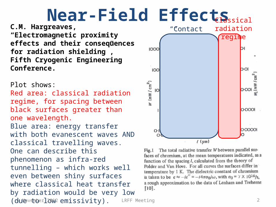
Near-Field Effects“Contact”
Classical radiation regimeC.M. Hargreaves, “Electromagnetic
proximity effects and their consequences for radiation shielding”, Fifth Cryogenic Engineering Conference.
Plot shows:Red area: classical radiation regime, for spacing between black surfaces greater than one wavelength.Blue area: energy transfer with both evanescent waves AND classical travelling waves. One can describe this phenomenon as infra-red tunnelling – which works well even between shiny surfaces where classical heat transfer by radiation would be very low (due to low emissivity).
There is a smooth transition between radiation and contact regimes – by applying mechanical pressure, size of the gap is simply reduced.
6 November 2012 2LRFF Meeting
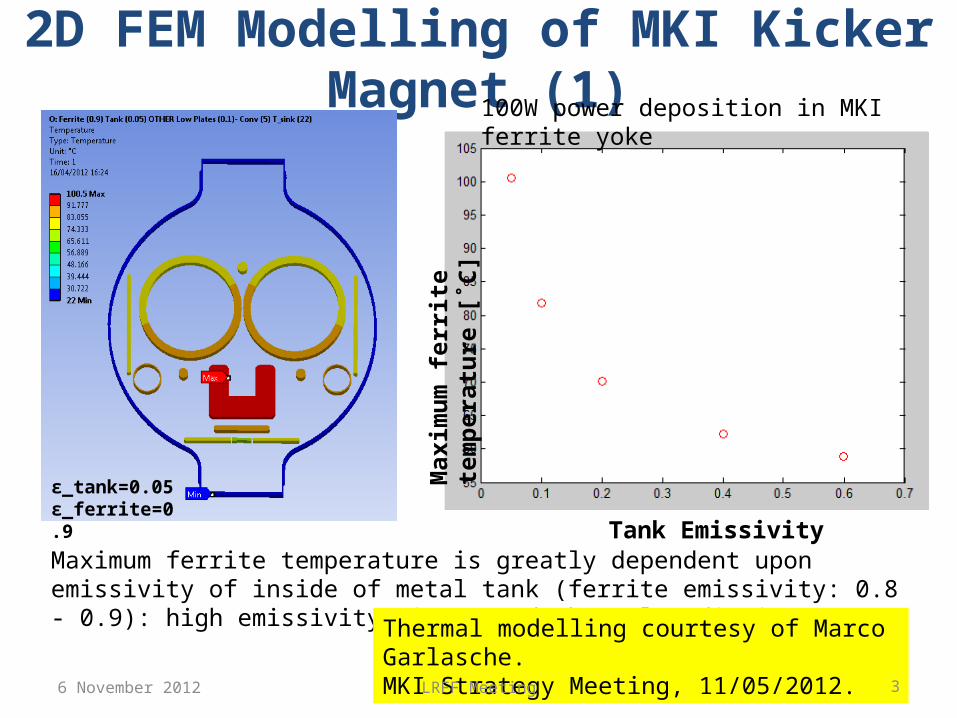
2D FEM Modelling of MKI Kicker Magnet (1)
ε_tank=0.05ε_ferrite=0.9
Tank Emissivity
Max
imum
ferr
ite te
mpe
ratu
re [˚
C]
Maximum ferrite temperature is greatly dependent upon emissivity of inside of metal tank (ferrite emissivity: 0.8 - 0.9): high emissivity gives good thermal radiation.
Thermal modelling courtesy of Marco Garlasche.MKI Strategy Meeting, 11/05/2012.
100W power deposition in MKI ferrite yoke
6 November 2012 3LRFF Meeting

Convection coefficient [W/m2-K @ 22 °C]:5 0.25 0
Analyses performed for different external tank convection coefficients (100W power deposition in MKI ferrite yoke)
2D FEM Modelling of MKI Kicker Magnet (2)
Tank Emissivity
Max
imum
ferr
ite te
mpe
ratu
re [˚
C]5
0.25
0
Maximum ferrite temperature is also greatly dependent upon external cooling of tank – this is especially true for high power depositions.
6 November 2012 4LRFF Meeting
ε_tank=0.05ε_ferrite=0.9
Thermal modelling courtesy of Marco Garlasche.MKI Strategy Meeting, 11/05/2012.
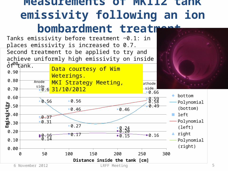
Measurements of MKI12 tank emissivity following an ion bombardment treatment
0 50 100 150 200 250 3000.00
0.10
0.20
0.30
0.40
0.50
0.60
0.70
0.80
0.90
1.00
0.160.14
0.150.20
0.16
0.730.76
0.59
0.69
0.56
0.310.37
0.46 0.46
0.66
0.490.56
0.74
0.27
0.170.24
0.58bottomPolynomial (bottom)leftPolynomial (left)rightPolynomial (right)topPolynomial (top)
Distance inside the tank [cm]
Emis
sivi
ty
Anode side
Cathode side
Data courtesy of Wim Weterings.MKI Strategy Meeting, 31/10/2012
Tanks emissivity before treatment ~0.1: in places emissivity is increased to 0.7. Second treatment to be applied to try and achieve uniformly high emissivity on inside of tank.
6 November 2012 5LRFF Meeting
How to Improve Heat TransferIncrease emissivity of surface of “heat source” and “heat sink”;• We cannot easily braze to a metallic surface – because of differential
expansion coefficients: only feasible with small volumes and mechanical pre-stress (delicate and risky).
• Alternative solutions for heat transfer include:– ion bombardment of metallic surface to increase emissivity (see next slide);
• Vacuum evaluation required.• Bake-out evaluation required.
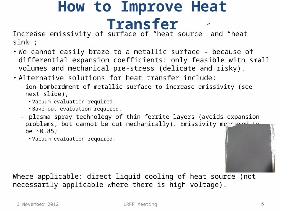
– plasma spray technology of thin ferrite layers (avoids expansion problems, but cannot be cut mechanically). Emissivity measured to be ~0.85;• Vacuum evaluation required.
Where applicable: direct liquid cooling of heat source (not necessarily applicable where there is high voltage).
6 November 2012 6LRFF Meeting