AS/NZS 5033:2014 - GSES · “AS/NZS 5033:2014 Installation and Safety Requirements for ... (i.e....
12
Creating sustainable change through education, communication and leadership AS/NZS 5033:2014 Revisions to the Grid-Connected PV Systems: Design and Installation Training Manual, 7th Edition
Transcript of AS/NZS 5033:2014 - GSES · “AS/NZS 5033:2014 Installation and Safety Requirements for ... (i.e....

AS/NZS 5033:2014 Revisions Page | i© GSES Pty Ltd
Creating sustainable change through education, communication and leadership
AS/NZS 5033:2014
Revisions to the Grid-Connected PV Systems: Design and Installation Training Manual, 7th Edition

AS/NZS 5033:2014 RevisionsPage | ii © GSES Pty Ltd
IntroductionThe new AS/NZS 5033:2014 has been released as of the 6th November 2014 and is applicable as of 6th February 2015 (3 months from the date of its publication). This document summarises any changes introduced by this 2014 revision of AS/NZS 5033 to the Grid-Connected PV Systems Design and Installation Manual 7th Edition (GSES). This document should be read in conjunction with the Grid-Connected PV Systems Design and Installation Manual 7th Edition (GSES) and the relevant revisions to parts of this publication are shown. Please note that the changes in this document are subject to alterations in newer editions of the Grid-Connected PV Systems Design and Installation manual and although this document has been prepared with utmost care it is the readers responsibility to review the AS/NZS 5033:2014 and apply the changes where you deem necessary.
ChangesFollowing is the summary of changes to the information within Grid-Connected PV Systems Design and Installation Manual 7th Edition (GSES), regarding the current AS/NZS 5033:2014.
Please Note: anything marked in RED relates to information currently not included in the manual but which will be included in the 8th Edition. Please note that these are subject to change.
Summary changes
1. All circuit diagrams involving a PV panel require a grounding connection for the panel.
According to AS/NZS 5033:2014 4.4.2, PV arrays with maximum voltage greater than ELV and in systems which include a.c. modules and microinverters with LV outputs shall earth all exposed module frames. Array mounting frames shall also be earthed.
Any images showing an unearthed array should be reconsidered.
2. Any AS/NZS 5033:2005 references must be changed to AS/NZS 5033:2014.
3. Voltage Drop
Maximum allowable voltage drop on the DC side of a Grid Connected PV System is now 3% for all applications from the furthest module in the system to the input of the power conversion equipment.
Keywords
Addition: Adding an additional paragraph.
Replacement: To entirely replace a sentence or paragraph.
Extension: To add an additional sentence/s onto the end of a sentence or paragraph.
Amendment: To modify sections of a paragraph or sentence either by quote or by reviewing the referenced text.
Removal: To remove something altogether.
Chapter 2
4. Section 2.10 - Licensing Requirements
Amendment:
“AS/NZS 5033:2014 Installation and Safety Requirements for photovoltaic (PV) arrays.”
Chapter 5
5. Section 5.10.2 - Blocking Diodes
Addition:
“Blocking diodes may not be used as a replacement for overcurrent protection” (AS/NZS 5033:2014 Clause 4.3.10)

AS/NZS 5033:2014 Revisions Page | iii© GSES Pty Ltd
6. Section 5.10.3 - Selecting Diodes
Amendment:
AS/NZS 5033:2014 clauses 4.3.9 and 4.3.10 outline the requirements for selecting and installing both bypass and blocking diodes, respectively.
Chapter 6
7. Section 6.5.1 – Modular Inverters
Addition:
“AS/NZS 5033:2014 outlines requirements for the installation of micro-inverters and DC conditioning units can be found in Clauses 4.3.12 and 2.1.5 respectively.”
Chapter 8
8. Section 8.1 - Introduction
Textual additon and amendment to Figure 8.1:
“According to AS/NZS 5033:2014 4.4.2, PV arrays with maximum voltage greater than ELV and in systems which include a.c. modules and microinverters with LV outputs shall earth all exposed module frames. Array mounting frames shall also be earthed”
The amended Figure 8.1 is below:
9. Section 8.2.1 - DC Cables
Addition after fifth paragraph (“These have a positive and negative...”):
“According to the provisions of AS/NZS 5033:2014, connectors shall be mated with connectors of the same type from the same manufacturer.” (AS/NZS 5033:2014 4.3.7)
10. Section 8.6.1 - PV Array DC Isolator
Addition after second paragraph (“AS/NZS 3000:2007 requires...”):
“It is possible to obtain inverters which contain an internal method of isolating an array. This switch-disconnection device must have a mechanical interlocking method with a replaceable module of the PCE in order to prevent the device going live during maintenance or inspection. The disconnection device shall not have exposed live parts in connected or disconnected state.” (For more information please see AS/NZS 5033:2014 4.4.1.2)

AS/NZS 5033:2014 RevisionsPage | iv © GSES Pty Ltd
11. Section 8.6.1 - PV Array DC Isolator
Extension to third paragraph (“The PV array DC isolator...”):
“The PV array DC isolator must be rated according to AS/NZS 5033:2014 and must be certified to AS/NZS 60898.2 or IEC 60947-2.”
12. Section 8.6.1 - PV Array DC Isolator
Replacement of final paragraph:
“Only non-polarised DC circuit breakers may now be installed. These switch-disconnectors shall meet the requirements of IEC 60947 and AS/NZS 5033:2014 Clause 4.3.5.”
13. Section 8.6.2 - Correct Wiring of Double Pole DC Circuit Breakers
Replacement within first paragraph (“It is anticipated that ...”):
“According to AS/NZS 5033:2014, polarised breakers cannot be disconnection devices. Polarised circuit breakers can no longer be installed but may be found on older installations.”(AS/NZS 5033:2014 3.3.3 and 4.3.5.2)
Chapter 10
14. Section 10.3.5 - Maximum System Voltage
Amendment to maximum module rating:
“Typically modules are rated to a maximum system voltage of 600V DC or 1000V DC. However, AS/NZS 5033:2014 states that the solar array for any domestic system is only allowed to have a PV array maximum voltage maximum open circuit voltage of 600VOC DC.” (AS/NZS 5033:2014 Clause 3.1)
Addition:
“The definition of domestic is defined as a building of Class 1, Class 2, Class 3 or Class 10 as per the National Construction Code (NCC) 2014 under the Australian Building Classifications” (AS/NZS 5033:2014 1.4.14)
Chapter 12
15. Section 12.1 - Determining the Protection Equipment and Switching
Figure 12.2 is amended to account for the compulsory grounding on the panels.
16. Section 12.2.1 - Fault Current Protection | Sizing Fault Current Protection Devices
Amendment to equation:
1.5 × ISC-MOD < Itrip < 2.4 × ISC-MOD
AND
Itrip ≤ IMOD MAX OCPR
(AS/NZS 5033:2014 3.3.5)

AS/NZS 5033:2014 Revisions Page | v© GSES Pty Ltd
17. Section 12.2.1 - Fault Current Protection | Sizing Fault Current Protection Devices
Amendment for dot points:
“Bi-directional/non-polarised (i.e. can break DC current flowing in both directions at full load and has a rating greater than or equal to PV array maximum voltage VOC. AS/NZS 5033:2014 clauses 4.3.1, 4.3.4 and 4.3.5).”
“Comply with all other specifications as per AS/NZS 5033:2014.”
18. Section 12.2.1 - Fault Current Protection | Sizing Fault Current Protection Devices
Addition after paragraph 2:
“A new set of calculations concerning current ratings of protection devices for strings which can be grouped in parallel which use one overcurrent protection device has been added. Please look at AS/NZS 5033:2014 3.3.5.1 for details.”
19. Section 12.2.3 - Sub-Array Protection
Amendment to equation
1.25 × ISC-MOD ≤ Itrip ≤ 2.4 × ISC-SUB-ARRAY (AS/NZS 5033:2014 Clause 3.3.5.2)
20. Section 12.3.1 - String Disconnection
Paragraph 1 of this section no longer applies .
21. Section 12.3.2 - Array Disconnection
Extension to first paragraph:
“...this is the PV array DC isolator and it shall be installed adjacent to the inverter array. If the inverter is not in direct line of sight of the solar array or is greater than 3m from it, a second isolator shall be installed at the array inverter as well. (AS/NZS 5033:2014 4.4.1.5)
22. Section 12.3.2 - Array Disconnection
Additional paragraph after 1st paragraph.
“Any PV array switch-disconnectors, except plugs and sockets, are to be readily available, and shall be marked with an identification name or number according to the PV array wiring diagram. An indicator of the PV array switch-disconnector being on or off must be used.”
23. Section 12.3.3 – Sub-Array Segmentation
Addition:
“According to AS/NZS 5033:2014 Clause 4.4.1.4, where multiple disconnection devices are required to isolate the inverter from the array they must all be able to operate simultaneously or all of the disconnection devices must be in a common location with a warning sign indicating the need to isolate all of the disconnection devices in order to isolate the equipment.”
24. Section 12.3.4 - ELV Segmentation
Removal of Section 12.3.4 - This is no longer relevant has been converted into a recommendation under AS/NZS 5033:2014.
25. Section 12.3.5 - AC Disconnection
Removal within Table 12.1:
String Cable Disconnection Devices are now a recommendation longer relevant under AS/NZS 5033:2014 and may be satisfied using non-load breaking plugs and sockets.
26. Section 12.4 - System Earthing
Amendment to second paragraph
“As noted in AS/NZS 5033:2014 Clause 4.4.2.1…”
AS/NZS 5033:2014 RevisionsPage | vi © GSES Pty Ltd
27. Section 12.4 - System Earthing
Replacement of third paragraph (AS/NZS 5033:2005 Figure 5.9 shows...):
”Figure 4.3 5 of AS/NZS 5033:2014 shows the ‘Earthing/Bonding Decision Tree’ which should be used in with the recommendations of AS/NZS 1768 and any lightning statistics or information about the number of thunder days per year within the vicinity of the installation.”
28. Section 12.4 - System Earthing
Replace Figure 12.10 with the updated figure in point 8 of this document (Figure 8.1).
Chapter 13
29. Section 13.1.1 - Current Carrying Capacity | Sub-array PV Systems
Replacement for section on PV Sub-Array Cables:
“If a fault current protection device is located in the sub-array cable, the sub-array cable must have a current rating equal to or greater than that of the fault current protection device.
If no fault current protection device has been included then the current carrying capacity of the cable must be the greater of:
Current rating of the PV array overcurrent protection device + 1.25 × sum of short circuit currents of all other sub-arrays
OR
1.25 × ISC of sub-array
If no overcurrent protection device is used you must use the inverter’s back-feed current value instead.”
30. Section 13.1.2.1 - DC Cables
Amendment to third paragraph “AS/NZS 5033:2014 specifies that the cables from the solar array to the inverter should be selected so that the voltage drop is less than or equal to 3% according to the CEC guidelines and AS/NZS 5033:2014. Therefore the sum of the voltage drop in the string plus the voltage drop in the PV array cables must be less than or equal to 3% according to the CEC guidelines and AS/NZS 5033:2014.”
31. Section 13.1.2.1 - DC Cables
Replacement of paragraph 8 (“Since the total voltage drop...”):
“The voltage drop between the array and the inverter is stated in the summary changes of this document. Best practice would be to size the individual cables (string and PV array) such that there is no more than 1.5% (As per AS/NZS 5033:2014) voltage drop in each cable. In the following examples a voltage drop of 3% will be used.”
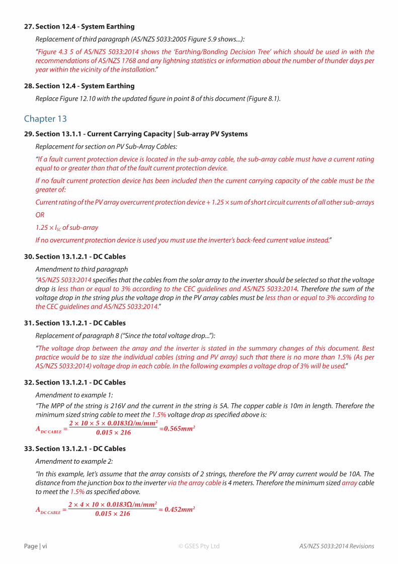
32. Section 13.1.2.1 - DC Cables
Amendment to example 1:“The MPP of the string is 216V and the current in the string is 5A. The copper cable is 10m in length. Therefore the minimum sized string cable to meet the 1.5% voltage drop as specified above is:
ADC CABLE = 0.015 × 216 =0.565mm2
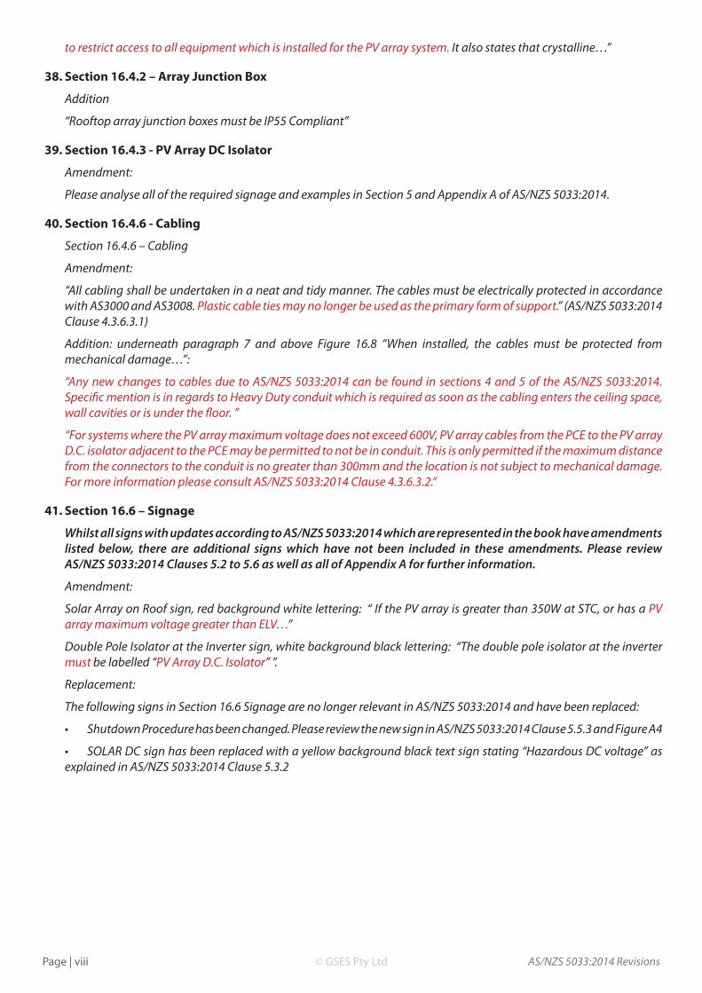
33. Section 13.1.2.1 - DC Cables
Amendment to example 2:
“In this example, let’s assume that the array consists of 2 strings, therefore the PV array current would be 10A. The distance from the junction box to the inverter via the array cable is 4 meters. Therefore the minimum sized array cable to meet the 1.5% as specified above.
ADC CABLE = 2 × 4 × 10 × 0.0183Ω/m/mm2
0.015 × 216 = 0.452mm2
2 × 10 × 5 × 0.0183Ω/m/mm2

AS/NZS 5033:2014 Revisions Page | vii© GSES Pty Ltd
34. Section 13.1.2.2 - AC Cables
Removal of second paragraph. This is to be replaced by the following:
“Although not mentioned in AS/NZS 5033:2014, AC voltage drop/rise should be kept as low as possible. The purpose of this is to keep the voltage rise to a minimum - this is to prevent voltage rise in the local grid. High levels of voltage in sections of the grid may lead to overvoltage tripping in grid connected inverters.
The allowable voltage rise depends upon the local state rules that are in effect. However, under the CEC Guidelines which were effective as of the 1st of February, 2013, the new recommended AC voltage drop/rise from the inverter to the point of connection of supply is less than 1%. State service rules may also contain information on voltage rise requirements.”
Amendment to Table 13.1
Location/ Cable Name Span Check Protection Size and Guidelines Reference
String Cable Between modules to where multiple strings join together
Is Fault Current Protection Installed?
YES: Rated trip current of the fault current protection.NO: 1.25 x ISC × (No. Strings -1)Min Voltage Rating: According to AS/NZS 5033:2014, clause 4.3.6 Table 4.2
AS/NZS 5033:2014 Clause 4.2 and 4.3.6Table 4.1 and 4.2
Sub Array Cable Between sub-array and PV array junction box, where multiple sub- array cables join together
Is Fault Current Protection Installed?
YES: Rated trip current of the fault current protection.NO: The greater of;Current rating of the PV array overcurrent protection device + 1.25 × (sum of ISC of other sub arrays)1.25 × ISC SUB ARRAY
Min Voltage Rating: According to AS/NZS 5033:2014, clause 4.3.6 Table 4.2
AS/NZS 5033:2014 Clause 4.2 and 4.3.6Table 4.1 and 4.2
Array Cable From array to inverter 1.25 × ISC MODULE/STRING/ARRAY
OR the prospective PCE back-feed current (whichever is greater)Min Voltage Rating: According to AS/NZS 5033:2014, clause 4.3.6 Table 4.2
AS/NZS 5033:2014 Clause 4.2 and 4.3.6Table 4.1 and 4.2
35. Chapter 13 Questions
Amendment to Question 5:
Voltage drop is now 3%.
Chapter 14
36. Section 14.1.6 - Voltage Drop: AC and DC Cables
Amendment to paragraphs 1 and 2:
“AS/NZS 5033:2014: Installation of Photovoltaic Arrays mandates a maximum voltage drop of 3% between the solar array and the inverter. This loss occurs in the cabling between these components. Since P = V × I, if there is a 3% voltage drop, there will be a 3% drop in power between the array and the inverter.
Since the cost of cable is less than solar modules, it is important that the voltage drop is minimised as much as possible. For example a 3% power drop in a 3000WP array is equivalent to the loss of the output of a 90WP solar module; which is worth much more than increasing the cable size slightly.”
Chapter 16
37. Section 16.4.1 - Solar Array
Addition before first paragraph:
“AS/NZS 5033:2014 Clause 3.1 states that the solar array is allowed to have a maximum open circuit voltage of PV array maximum voltage of 600VOC DC for any domestic system. Any system in excess of 600VOC will require a method
AS/NZS 5033:2014 RevisionsPage | viii © GSES Pty Ltd
to restrict access to all equipment which is installed for the PV array system. It also states that crystalline…”
38. Section 16.4.2 – Array Junction Box
Addition
“Rooftop array junction boxes must be IP55 Compliant”
39. Section 16.4.3 - PV Array DC Isolator
Amendment:
Please analyse all of the required signage and examples in Section 5 and Appendix A of AS/NZS 5033:2014.
40. Section 16.4.6 - Cabling
Section 16.4.6 – Cabling
Amendment:
“All cabling shall be undertaken in a neat and tidy manner. The cables must be electrically protected in accordance with AS3000 and AS3008. Plastic cable ties may no longer be used as the primary form of support.” (AS/NZS 5033:2014 Clause 4.3.6.3.1)
Addition: underneath paragraph 7 and above Figure 16.8 “When installed, the cables must be protected from mechanical damage…”:
“Any new changes to cables due to AS/NZS 5033:2014 can be found in sections 4 and 5 of the AS/NZS 5033:2014. Specific mention is in regards to Heavy Duty conduit which is required as soon as the cabling enters the ceiling space, wall cavities or is under the floor. ”
“For systems where the PV array maximum voltage does not exceed 600V, PV array cables from the PCE to the PV array D.C. isolator adjacent to the PCE may be permitted to not be in conduit. This is only permitted if the maximum distance from the connectors to the conduit is no greater than 300mm and the location is not subject to mechanical damage. For more information please consult AS/NZS 5033:2014 Clause 4.3.6.3.2.”
41. Section 16.6 – Signage
Whilst all signs with updates according to AS/NZS 5033:2014 which are represented in the book have amendments listed below, there are additional signs which have not been included in these amendments. Please review AS/NZS 5033:2014 Clauses 5.2 to 5.6 as well as all of Appendix A for further information.
Amendment:
Solar Array on Roof sign, red background white lettering: “ If the PV array is greater than 350W at STC, or has a PV array maximum voltage greater than ELV…”
Double Pole Isolator at the Inverter sign, white background black lettering: “The double pole isolator at the inverter must be labelled “PV Array D.C. Isolator” ”.
Replacement:
The following signs in Section 16.6 Signage are no longer relevant in AS/NZS 5033:2014 and have been replaced:
• ShutdownProcedurehasbeenchanged.PleasereviewthenewsigninAS/NZS5033:2014Clause5.5.3and Figure A4
• SOLARDCsignhasbeenreplacedwithayellowbackgroundblacktextsignstating“HazardousDCvoltage”asexplained in AS/NZS 5033:2014 Clause 5.3.2

AS/NZS 5033:2014 Revisions Page | ix© GSES Pty Ltd
• PVARRAYMAINSWITCHisnolongerallowedandmustbenamed“PVArrayD.C.Isolator”
Chapter 17
42. Section 17.2 - System Documentation
Additions to list of documentation:
Shut down and isolation procedure for emergency maintenance.
Engineering certificate for wind and mechanical loading.
Installer/designer declaration of compliance with wind and mechanical loading.
Operating instructions.
Contact details for personnel related to installation queries and system support.
Additional documentation can be found in AS/NZS 5033:2014 Clause 5.7.”
43. Section 17.3 - System Installation & Pre-Commissioning Checklist
Amendment:
PV wiring losses are stated in the summary changes of this document.
Chapter 19
44. Section 19.3 - Designing a Large PV Grid Connected System
Amendment to paragraph 10:
“If we assume a voltage drop in the cables of 3%, then the voltage at the inverter for each module would be 0.97 × 30.85V = 29.92V.”
List of locations where AS/NZS 5033:2005 has been cited. The usage of AS/NZS 5033:2005 in these sections has been checked to see that they hold a 2014 counterpart. In addition, the following places where AS/NZS 5033:2005 has been used must have the following change: 2005 to 2014. Any clauses from AS/NZS 5033:2005 in the Grid-Connected PV Systems Design and Installation 7th edition manual listed below will have their AS/NZS 5033:2014 equivalent listed in the table at the bottom:
Section:
2.10 - No Clause. Change of the name of the standard is required.
8.6.1 - No Clause. Equivalent clauses can be found in AS/NZS 5033:2014 Section 4.
12.2.1 - No Clause. Section reference found. Equivalent clauses found from AS/NZS 5033:2014 Clause 3.3.4 and onwards.
Figure 12.5 - Clauses 2.4.1 and 3.4.1. Equivalents can be found in the table below.
Figure 12.6 - Clauses 2.4.3, 2.5.3 and 3.4.1. Equivalents can be found in the table below.
12.2.2 - Clause 3.4.1. Equivalent can be found in the table below
Figure 12.7 - Clause 2.4.5. Equivalent can be found in the table below
12.3.1 - Equivalent sections for string disconnection and array disconnection can be found in AS/NZS 5033:2014 Section 3. AS/NZS 5033:2014 Table 4.1 3 is also relevant.
12.3.2 - Equivalent sections for string disconnection and array disconnection can be found in AS/NZS 5033:2014 Section 3. AS/NZS 5033:2014 Table 4.1 3 is also relevant.
Figure 12.8 - Clauses 2.4.3 and 2.5.3. Equivalent can be found in the table below.
12.3.5 - No Clause. Name change of standard required.
Figure 12.9 - Clauses 2.4.3, 2.5.3 and 2.5.4. Equivalents can be found in the table be
13.1 - No direct relation to cable selection in AS/NZS 5033:2005. There is, however, relation to the need that all components in the system must be equal have a minimum voltage rating of to the PV Array Maximum Voltage.
AS/NZS 5033:2014 RevisionsPage | x © GSES Pty Ltd
13.1.1 - No clause regarding to non - UPS. Equivalent found in AS/NZS 5033:2014 Table 4.2 and 4.3. Clause 3.3 regards to UPS battery based systems.
13.1.2.2 - No clause. Equivalent found in clause 4.4.4.3. The maximum voltage drop referenced in section 13.1.2.2 - AC Cables, can be found in AS/NZS 5033:2014 2.1.10c).
Figure 13.3 - Clauses 2.4.1, 2.4.5 and 3.4.1. Equivalent clauses can be found in the table below. The caption note which regards the lack of system earthing can no longer be allowed due to AS/NZS 5033: 4.4.2. This shall be updated for future editions.
Table 13.1 - All clauses can be found in the table below. All minimum voltage ratings must adhere to AS/NZS 5033:2014 4.2.
14.1.6 - Voltage drop clause required. The equivalent is in section 2.10. AS/NZS 5033:2014 2.1.10c) .
14.1.6.1 - Figure 14.6 has no earthing present. This is due to the fact that the figure regards voltage rise only. AS/NZS 5033:2014 4.4.2.
16.1 - Change standard name to “AS/NZS 5033:2014 Installation and Safety Requirements for photovoltaic (PV) arrays.”
16.4.1 - Equivalent found for the first statement in 16.4.1 Solar Array: AS/NZS 5033:2014 Clause 4.3.2.1.
16.4.6 - Installation with particular attention to protecting the cables from external influences is found under AS/NZS 5033:2014 4.3.6.
16.6 - Sign requirements are found in AS/NZS 5033:2014 Clauses 5.2 to 5.6 and examples can be found in Appendix A (pp. 51- 55).
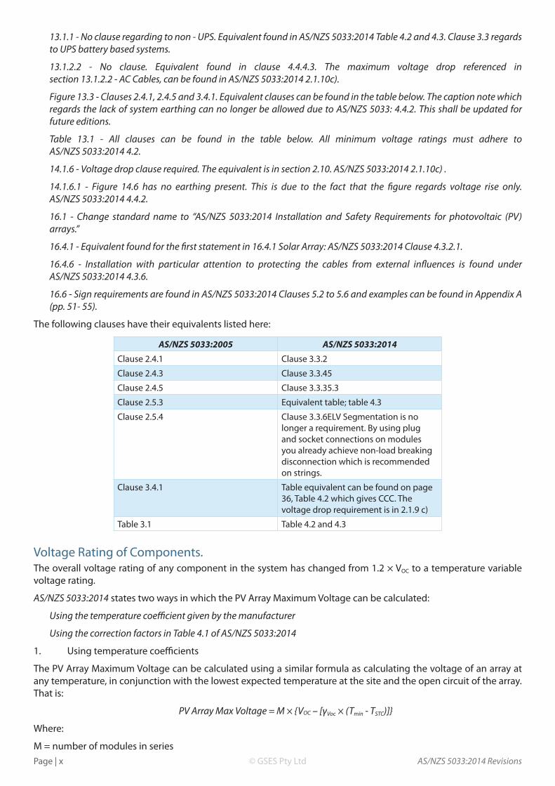
The following clauses have their equivalents listed here:
AS/NZS 5033:2005 AS/NZS 5033:2014
Clause 2.4.1 Clause 3.3.2
Clause 2.4.3 Clause 3.3.45
Clause 2.4.5 Clause 3.3.35.3
Clause 2.5.3 Equivalent table; table 4.3
Clause 2.5.4 Clause 3.3.6ELV Segmentation is no longer a requirement. By using plug and socket connections on modules you already achieve non-load breaking disconnection which is recommended on strings.
Clause 3.4.1 Table equivalent can be found on page 36, Table 4.2 which gives CCC. The voltage drop requirement is in 2.1.9 c)
Table 3.1 Table 4.2 and 4.3
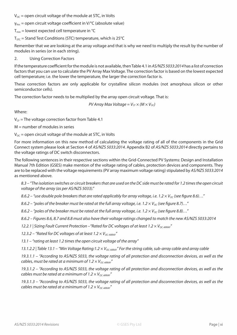
Voltage Rating of Components.The overall voltage rating of any component in the system has changed from 1.2 × VOC to a temperature variable voltage rating.
AS/NZS 5033:2014 states two ways in which the PV Array Maximum Voltage can be calculated:
Using the temperature coefficient given by the manufacturer
Using the correction factors in Table 4.1 of AS/NZS 5033:2014
1. Using temperature coefficients
The PV Array Maximum Voltage can be calculated using a similar formula as calculating the voltage of an array at any temperature, in conjunction with the lowest expected temperature at the site and the open circuit of the array. That is:
PV Array Max Voltage = M × {VOC – [γVoc × (Tmin - TSTC)]}
Where:
M = number of modules in series
AS/NZS 5033:2014 Revisions Page | xi© GSES Pty Ltd
VOC = open circuit voltage of the module at STC, in Volts
γVoc = open circuit voltage coefficient in V/°C (absolute value)
Tmin = lowest expected cell temperature in °C
TSTC = Stand Test Conditions (STC) temperature, which is 25°C
Remember that we are looking at the array voltage and that is why we need to multiply the result by the number of modules in series (or in each string).
2. Using Correction Factors
If the temperature coefficient for the module is not available, then Table 4.1 in AS/NZS 5033:2014 has a list of correction factors that you can use to calculate the PV Array Max Voltage. The correction factor is based on the lowest expected cell temperature; i.e. the lower the temperature, the larger the correction factor is.
These correction factors are only applicable for crystalline silicon modules (not amorphous silicon or other semiconductor cells).
The correction factor needs to be multiplied by the array open circuit voltage. That is:
PV Array Max Voltage = VCF × (M × VOC)
Where:
VCF = The voltage correction factor from Table 4.1
M = number of modules in series
VOC = open circuit voltage of the module at STC, in Volts
For more information on this new method of calculating the voltage rating of all of the components in the Grid Connect system please look at Section 4 of AS/NZS 5033:2014. Appendix B2 of AS/NZS 5033:2014 directly pertains to the voltage ratings of DC switch disconnectors.
The following sentences in their respective sections within the Grid-Connected PV Systems: Design and Installation Manual 7th Edition (GSES) make mention of the voltage rating of cables, protection devices and components. They are to be replaced with the voltage requirements (PV array maximum voltage rating) stipulated by AS/NZS 5033:2014 as mentioned above.
8.3 – “The isolation switches or circuit breakers that are used on the DC side must be rated for 1.2 times the open circuit voltage of the array (as per AS/NZS 5033).”
8.6.2 – “use double pole breakers that are rated applicably for array voltage, i.e. 1.2 × VOC (see figure 8.6)…”
8.6.2 – “poles of the breaker must be rated at the full array voltage, i.e. 1.2 × VOC (see figure 8.7)…”
8.6.2 – “poles of the breaker must be rated at the full array voltage, i.e. 1.2 × VOC (see figure 8.8)…”
8.6.2 – Figures 8.6, 8.7 and 8.8 must also have their voltage ratings changed to match the new AS/NZS 5033:2014
12.2.1 | Sizing Fault Current Protection –“Rated for DC voltages of at least 1.2 × VOC-ARRAY”
12.3.2 – “Rated for DC voltages of at least 1.2 × VOC-ARRAY”
13.1 – “rating at least 1.2 times the open circuit voltage of the array”
13.1.2.2 | Table 13.1 – “Min Voltage Rating:1.2 × VOC-ARRAY” For the string cable, sub-array cable and array cable
19.3.1.1 – “According to AS/NZS 5033, the voltage rating of all protection and disconnection devices, as well as the cables, must be rated at a minimum of 1.2 × VOC-ARRAY”
19.3.1.2 – “According to AS/NZS 5033, the voltage rating of all protection and disconnection devices, as well as the cables must be rated at a minimum of 1.2 × VOC-ARRAY”
19.3.1.3 – “According to AS/NZS 5033, the voltage rating of all protection and disconnection devices, as well as the cables must be rated at a minimum of 1.2 × VOC-ARRAY”

AS/NZS 5033:2014 RevisionsPage | xii © GSES Pty Ltd
Voltage Correction Factors for Crystalline and Multi-Crystalline Silicon PV ModulesThis is table 4.1 from AS/NZS 5033:2014. It is used in the calculation of PV array maximum voltage in the event that the VOC temperature coefficient of the solar modules is not known.
Lowest expected operating temperature (°C)
Correction Factor
24 to 20 1.02
19 to 15 1.04
14 to 10 1.06
9 to 5 1.08
4 to 0 1.10
-1 to -5 1.12
-6 to -10 1.14
-11 to -15 1.16
-16 to -20 1.18
-21 to -25 1.20
-26 to -30 1.21
-31 to -35 1.23
-36 to -40 1.25
(Source: AS/NZS 5033:2014 Table 4.1)
In the event that the table mentioned above differs from the intended table (AS/NZS 5033:2014 Table 4.1), AS/NZS 5033:2014 will take priority.