Asme Viii d1 Ma Appendix 1
19
Mandatory Appendices COPYRIGHT American Society of Mechanical Engineers Licensed by Information Handling Services COPYRIGHT American Society of Mechanical Engineers Licensed by Information Handling Services
-
Upload
chihiya-fitria-nurhayati -
Category
Documents
-
view
337 -
download
7
description
xv
Transcript of Asme Viii d1 Ma Appendix 1

Mandatory Appendices
COPYRIGHT American Society of Mechanical EngineersLicensed by Information Handling ServicesCOPYRIGHT American Society of Mechanical EngineersLicensed by Information Handling Services

COPYRIGHT American Society of Mechanical EngineersLicensed by Information Handling ServicesCOPYRIGHT American Society of Mechanical EngineersLicensed by Information Handling Services

ASME B&PVC SEC81$$U85 04-15-00 11:03:52 pd: sec81 Rev 15.03
MANDATORY APPENDICES A99
Appendix 1 Supplementary Design Formulas. . . . . . . . . . . . . . . . . . . . . . . . . . . . . . . . . . . . . . . . . . . . . . 315Appendix 2 Rules for Bolted Flange Connections With Ring Type Gaskets. . . . . . . . . . . . . . . . . . 331Appendix 3 Definitions. . . . . . . . . . . . . . . . . . . . . . . . . . . . . . . . . . . . . . . . . . . . . . . . . . . . . . . . . . . . . . . . . 351Appendix 4 Rounded Indications Charts Acceptance Standard for Radiographically
Determined Rounded Indications in Welds. . . . . . . . . . . . . . . . . . . . . . . . . . . . . . . . . . . 355Appendix 6 Methods for Magnetic Particle Examination (MT). . . . . . . . . . . . . . . . . . . . . . . . . . . . . . 363Appendix 7 Examination of Steel Castings. . . . . . . . . . . . . . . . . . . . . . . . . . . . . . . . . . . . . . . . . . . . . . . . 365Appendix 8 Methods for Liquid Penetrant Examination (PT). . . . . . . . . . . . . . . . . . . . . . . . . . . . . . . . 369Appendix 9 Jacketed Vessels. . . . . . . . . . . . . . . . . . . . . . . . . . . . . . . . . . . . . . . . . . . . . . . . . . . . . . . . . . . . 371Appendix 10 Quality Control System. . . . . . . . . . . . . . . . . . . . . . . . . . . . . . . . . . . . . . . . . . . . . . . . . . . . . . 381Appendix 11 Capacity Conversions for Safety Valves. . . . . . . . . . . . . . . . . . . . . . . . . . . . . . . . . . . . . . . 385Appendix 12 Ultrasonic Examination of Welds (UT). . . . . . . . . . . . . . . . . . . . . . . . . . . . . . . . . . . . . . . . 389Appendix 13 Vessels of Noncircular Cross Section. . . . . . . . . . . . . . . . . . . . . . . . . . . . . . . . . . . . . . . . . 391Appendix 14 Integral Flat Heads With a Large, Single, Circular, Centrally-Located
Opening. . . . . . . . . . . . . . . . . . . . . . . . . . . . . . . . . . . . . . . . . . . . . . . . . . . . . . . . . . . . . . . . . 439Appendix 16 Submittal of Technical Inquiries to the Boiler and Pressure Vessel
Committee. . . . . . . . . . . . . . . . . . . . . . . . . . . . . . . . . . . . . . . . . . . . . . . . . . . . . . . . . . . . . . . 443Appendix 17 Dimpled or Embossed Assemblies. . . . . . . . . . . . . . . . . . . . . . . . . . . . . . . . . . . . . . . . . . . . 445Appendix 18 Adhesive Attachment of Nameplates. . . . . . . . . . . . . . . . . . . . . . . . . . . . . . . . . . . . . . . . . . 457Appendix 19 Electrically Heated or Gas Fired Jacketed Steam Kettles. . . . . . . . . . . . . . . . . . . . . . . . 459Appendix 20 Hubs of Tubesheets and Flat Heads Machined From Plate. . . . . . . . . . . . . . . . . . . . . . 461Appendix 21 Jacketed Vessels Constructed of Work-Hardened Nickel. . . . . . . . . . . . . . . . . . . . . . . . . 463Appendix 22 Integrally Forged Vessels. . . . . . . . . . . . . . . . . . . . . . . . . . . . . . . . . . . . . . . . . . . . . . . . . . . . 465Appendix 23 External Pressure Design of Copper, Copper Alloy, and Titanium Alloy
Condenser and Heat Exchanger Tubes With Integral Fins. . . . . . . . . . . . . . . . . . . . . 467Appendix 24 Design Rules for Clamp Connections. . . . . . . . . . . . . . . . . . . . . . . . . . . . . . . . . . . . . . . . . 469Appendix 25 Acceptance of Testing Laboratories and Authorized Observers for Capacity
Certification of Pressure Relief Valves. . . . . . . . . . . . . . . . . . . . . . . . . . . . . . . . . . . . . . 477Appendix 26 Pressure Vessel and Heat Exchanger Expansion Joints. . . . . . . . . . . . . . . . . . . . . . . . . . 479Appendix 27 Alternative Requirements for Glass-Lined Vessels. . . . . . . . . . . . . . . . . . . . . . . . . . . . . . 491Appendix 28 Alternative Corner Weld Joint Detail for Box Headers for Air-Cooled Heat
Exchangers. . . . . . . . . . . . . . . . . . . . . . . . . . . . . . . . . . . . . . . . . . . . . . . . . . . . . . . . . . . . . . . 493Appendix 29 Requirements for Steel Bars of Special Section for Helically Wound
Interlocking Strip Layered Pressure Vessels. . . . . . . . . . . . . . . . . . . . . . . . . . . . . . . . . . 495Appendix 30 Rules for Drilled Holes Not Penetrating Through Vessel Wall. . . . . . . . . . . . . . . . . . . 499Appendix 31 Rules for Cr–Mo Steels With Additional Requirements for Welding and Heat
Treatment. . . . . . . . . . . . . . . . . . . . . . . . . . . . . . . . . . . . . . . . . . . . . . . . . . . . . . . . . . . . . . . .500.1
313
[This is electronic file SEC81$$$86 page # 313
A99
A00
COPYRIGHT American Society of Mechanical EngineersLicensed by Information Handling ServicesCOPYRIGHT American Society of Mechanical EngineersLicensed by Information Handling Services

ASME B&PVC SEC81$$U85 04-15-00 11:03:52 pd: sec81 Rev 15.03
[Blank Page] This is electronic page # 314 [Blank Page]
COPYRIGHT American Society of Mechanical EngineersLicensed by Information Handling ServicesCOPYRIGHT American Society of Mechanical EngineersLicensed by Information Handling Services

APPENDIX 1SUPPLEMENTARY DESIGN FORMULAS
1-1 THICKNESS OF CYLINDRICALAND SPHERICAL SHELLS
(a) The following formulas, in terms of the outsideradius, are equivalent to and may be used instead ofthose given in UG-27(c) and (d).
(1) For cylindrical shells (circumferential stress),
t pPRo
SE+ 0.4Por P p
SEt
Ro − 0.4t(1)
whereRop outside radius of the shell course under consid-
eration, in.(2) For spherical shells,
t pPRo
2SE+ 0.8Por P p
2SEt
Ro − 0.8t(2)
Other symbols are asdefined in UG-27.
1-2 THICK CYLINDRICAL SHELLS
(a)(1) Circumferential Stress (Longitudinal Joints).When the thickness of the cylindrical shell under internaldesign pressure exceeds one-half of the inside radius,or when P exceeds 0.385SE, the following formulasshall apply:
When P is known andt is desired,
t p R(Z1⁄2 − 1) p Ro
(Z1⁄2 −1)
Z1⁄2
(1)
where
Z pSE+ P
SE− P
315
Where t is known andP is desired,
P p SE1Z − 1
Z + 12 (2)
where
Z p 1R + t
R 22
p 1Ro
R22
p 1 Ro
Ro −t22
(2) Longitudinal Stress (Circumferential Joints).When the thickness of the cylindrical shell under internaldesign pressure exceeds one-half of the inside radius,or when P exceeds 1.25SE, the following formulasshall apply:
When P is known andt is desired,
t p R (Z1⁄2 − 1) p Ro 1Z
1⁄2 −1
Z1⁄2
2 (3)
where
Z p 1 P
SE+ 12
When t is known andP is desired,
P p SE(Z − 1) (4)
COPYRIGHT American Society of Mechanical EngineersLicensed by Information Handling ServicesCOPYRIGHT American Society of Mechanical EngineersLicensed by Information Handling Services

1-2 1998 SECTION VIII — DIVISION 1 1-4
where
Z p 1R + t
R 22
p 1Ro
R 22
p1 Ro
Ro − t22
Symbols are as defined in UG-27 and 1-1.
1-3 THICK SPHERICAL SHELLS
When the thickness of the shell of a wholly sphericalvessel or of a hemispherical head under internal designpressure exceeds 0.356R, or whenP exceeds 0.665SE,the following formulas shall apply:
When P is known andt is desired,
t p R(Y1⁄3 − 1) p Ro 1Y
1⁄3 −1
Y1⁄3
2 (1)
where
Y p2(SE+ P)
2SE− P
When t is known andP is desired,
P p 2SE1Y − 1
Y + 22 (2)
where
Y p 1R + t
R 23
p 1 Ro
Ro − t23
Symbols are as defined in UG-27 and 1-1.
1-4 FORMULAS FOR THE DESIGN OFFORMED HEADS UNDERINTERNAL PRESSURE
(a) The formulas of this paragraph provide for thedesign of formed heads of proportions other than thosegiven in UG-32, in terms of inside and outside diameter.
316
(b) The symbols defined below are used in theformulas of this paragraph (see Fig. 1-4):
tp minimum required thickness of head after form-ing, in.
Pp internal design pressure (see UG-21), psiDp inside diameter of the head skirt; or inside length
of the major axis of an ellipsoidal head; or insidediameter of a cone head at the point under con-sideration measured perpendicular to the longi-tudinal axis, in.
Dop outside diameter of the head skirt; or outsidelength of the major axis of an ellipsoidal head;or outside diameter of a cone head at the pointunder consideration measured perpendicular tothe longitudinal axis, in.
Sp maximum allowable working stress, as given inSubsection C, psi, except as limited by footnote1 to 1-4(c) and (d), UG-24, UG-32(e), andUW-12.
Ep lowest efficiency of any Category A joint inthe head (for hemispherical heads this includeshead-to-shell joint). For welded vessels, use theefficiency specified in UW-12.
rp inside knuckle radius, in.Lp inside spherical or crown radius for torispherical
and hemispherical heads, in.Lp K1D for ellipsoidal heads in whichK1 is ob-
tained from Table UG-37, in.Lop outside spherical or crown radius, in.
L / rp ratio of the inside crown radius to the insideknuckle radius, used in Table 1-4.2
Mp a factor in the formulas for torispherical headsdepending on the head proportionL / r
hp one-half of the length of the minor axis of theellipsoidal head, or the inside depth of the ellip-soidal head measured from the tangent line(head-bend line), in.
Kp a factor in the formulas for ellipsoidal headsdepending on the head proportionD / 2h
D / 2hp ratio of the major to the minor axis of ellipsoidalheads, which equals the inside diameter of theskirt of the head divided by twice the insideheight of the head, and is used in Table 1-4.1
ap one-half of the included (apex) angle of the coneat the center line of the head
(c) Ellipsoidal Heads1
t pPDK
2SE− 0.2Por P p
2SEt
KD + 0.2t(1)
1 Ellipsoidal heads designed underK > 1.0 and all torispherical headsmade of materials having a specified minimum tensile strengthexceeding 80,000 psi shall be designed using a value ofS equal to
COPYRIGHT American Society of Mechanical EngineersLicensed by Information Handling ServicesCOPYRIGHT American Society of Mechanical EngineersLicensed by Information Handling Services

1-4 APPENDIX 1 — MANDATORY 1-4
FIG. 1-4 PRINCIPAL DIMENSIONS OF TYPICAL HEADS
TABLE 1-4.1VALUES OF FACTOR K
(Use Nearest Value of D/2h; Interpolation Unnecessary)
D/2h 3.0 2.9 2.8 2.7 2.6 2.5 2.4 2.3 2.2 2.1 2.0K 1.83 1.73 1.64 1.55 1.46 1.37 1.29 1.21 1.14 1.07 1.00
D/2h 1.9 1.8 1.7 1.6 1.5 1.4 1.3 1.2 1.1 1.0 . . .K 0.93 0.87 0.81 0.76 0.71 0.66 0.61 0.57 0.53 0.50 . . .
t pPDoK
2SE+ 2P(K − 0.1)
or
P p2SEt
KDo − 2t (K − 0.1)(2)
where
K p1
6 32 + 1D
2h22
420,000 psi at room temperature and reduced in proportion to thereduction in maximum allowable stress values at temperature for thematerial as shown in the appropriate table (see UG-23).
317
Numerical values of the factorK are given in Table1-4.1.
Example 1.2 Determine the required thicknesst ofa seamless ellipsoidal head, exclusive of provision forcorrosion for the following conditions:
D p 40 in; h p 9 in; P p 200 psi; S p 13,750psi; E p 1.00.
D
2hp
40
18p 2.22
2 This calculation is intended only to illustrate the use of the formulaherein. Other paragraphs in this Division may have to be satisfiedto permit use of the full tabular stress value.
COPYRIGHT American Society of Mechanical EngineersLicensed by Information Handling ServicesCOPYRIGHT American Society of Mechanical EngineersLicensed by Information Handling Services

1-4 1998 SECTION VIII — DIVISION 1 1-4
From Table 1-4.1,K p 1.14. Substituting in Eq. (1),
t p200 × 40 × 1.14
[2 × 13,750 × (1.00) − (0.2 × 200)]p 0.33 in.
Example 2.2 Determine the maximum allowableworking pressureP of a seamless ellipsoidal head forthe following conditions:
D p 30 in.; h p 7.5 in.; total thicknessp 1⁄2 in.with no allowance for corrosion; maximum operatingtemperaturep 800°F; E p 1.00.
From the appropriate table given in Subpart 1 ofSection II, Part D,S p 10,200 psi.
D
2hp
30
15p 2.0
From Table 1-4.1,K p 1.0. Substituting in Eq. (1),
P p2 × 10,200 × 1.0 × 0.5
[1 × 30 + (0.2 × 0.5)]p 339 psi
(d) Torispherical Heads1
t pPLM
2SE− 0.2Por P p
2SEt
LM + 0.2t(3)
t pPLoM
2SE+ P(M − 0.2)
or
P p2SEt
MLo − t (M − 0.2)(4)
where
M p 1⁄4 13 + ! L
r 2
318
Numerical values of the factorM are given in Table1-4.2.
Example 1.2Determine the required thicknesst, exclu-sive of allowance for corrosion, of a torispherical headfor the following conditions:
D p 40 in.; L p 40 in.; r p 4 in.; P p 200 psi;S p 13,750 psi;E p 1.00 (seamless head).
L
rp
40
4p 10
and from Table 1-4.2,M p 1.54. Substituting in Eq.(3),
t p200 × 40 × 1.54
[2 × 13,750 × (1.00) − (0.2 × 200)]p 0.45 in.
Example 2.2Determine the maximum allowable work-ing pressureP of a torispherical head for the followingconditions:
D p 30 in.; L p 24 in.; r p 2.00 in.; E p 1.00(seamless head); total thicknessp 0.5 in. with noallowance for corrosion; material conforms to SA-515Grade 70; maximum operating temperaturep 900°F.
From the appropriate table given in Subpart 1 ofSection II, Part D,S p 6500 psi.
L
rp
24
2.00p 12.0
From Table 1-4.2,M p 1.62. Substituting in Eq. (3),
P p2 × 6500 × 1.0 × 0.5
24 × 1.62 + 0.2 × 0.5p 167 psi
(e) Conical Heads
t pPD
2 cosa (SE− 0.6P)
or
P p2SEtcosa
D + 1.2t cosa(5)
t pPDo
2 cosa (SE+ 0.4P)
COPYRIGHT American Society of Mechanical EngineersLicensed by Information Handling ServicesCOPYRIGHT American Society of Mechanical EngineersLicensed by Information Handling Services

1-4 APPENDIX 1 — MANDATORY 1-5
TABLE 1-4.2VALUES OF FACTOR M
(Use Nearest Value of L/r; Interpolation Unnecessary)
L/r 1.0 1.25 1.50 1.75 2.00 2.25 2.50 2.75 3.00 3.25 3.50M 1.00 1.03 1.06 1.08 1.10 1.13 1.15 1.17 1.18 1.20 1.22
L/r 4.0 4.5 5.0 5.5 6.0 6.5 7.0 7.5 8.0 8.5 9.0M 1.25 1.28 1.31 1.34 1.36 1.39 1.41 1.44 1.46 1.48 1.50
L/r 9.5 10.00 10.5 11.0 11.5 12.0 13.0 14.0 15.0 16.0 162⁄31
M 1.52 1.54 1.56 1.58 1.60 1.62 1.65 1.69 1.72 1.75 1.77
NOTE:(1) Maximum ratio allowed by UG-32(j) when L equals the outside diameter of the skirt of the head.
or
P p2SEtcosa
Do − 0.8t cosa(6)
1-5 RULES FOR CONICAL REDUCERSECTIONS AND CONICAL HEADSUNDER INTERNAL PRESSURE
(a) The formulas of (d) and (e) below provide forthe design of reinforcement, if needed, at the cone-to-cylinder junctions for conical reducer sections andconical heads where all the elements have a commonaxis and the half-apex anglea ≤ 30 deg. Subparagraph(g) below provides for special analysis in the designof cone-to-cylinder intersections with or without rein-forcing rings wherea is greater than 30 deg.
In the design of reinforcement for a cone-to-cylinderjuncture, the requirements of UG-41 shall be met.
(b) NomenclatureArL p required area of reinforcement at large end of
cone, in.2
Arsp required area of reinforcement at small end ofcone, in.2
AeLp effective area of reinforcement at large end in-tersection, in.2
Aesp effective area of reinforcement at small end in-tersection, in.2
Esp modulus of elasticity of cylinder material, psiEcp modulus of elasticity of cone material, psiEr p modulus of elasticity of reinforcing ring mate-
rial, psiE1p efficiency of longitudinal joint in cylinder. For
compression (such as at large end of cone),E1 p 1.0 for butt welds.
E2p efficiency of longitudinal joint in cone. For com-pression,E2 p 1.0 for butt welds.
319
f1p axial load at large end due to wind, dead load,etc., excluding pressure, lb /in.
f2p axial load at small end due to wind, dead load,etc., excluding pressure, lb /in.
Pp internal design pressure (see UG-21), psiQLp algebraical sum ofPRL /2 andf1, lb /in.Qsp algebraical sum ofPRs /2 andf2, lb /in.Rsp inside radius of small cylinder at small end of
cone, in.RLp inside radius of large cylinder at large end of
cone, in.Ssp allowable stress of cylinder material at design
temperature, psiScp allowable stress of cone material at design tem-
perature, psiSr p allowable stress of reinforcing ring material at
design temperature, psitp minimum required thickness of cylinder at
cone-to-cylinder junction, in.tcp nominal thickness of cone at cone-to-cylinder
junction, in.tr p minimum required thickness of cone at cone-
to-cylinder junction, in.tsp nominal thickness of cylinder at cone-to-cylin-
der junction, in.ap half-apex angle of cone or conical section, deg.Dp angle indicating need for reinforcement at cone-
to-cylinder junction having a half-apex anglea≤ 30 deg. WhenD ≥ a, no reinforcement isrequired at the junction (see Tables 1-5.1 and1-5.2), deg.
yp cone-to-cylinder factorp SsEs for reinforcing ring on shellp ScEc for reinforcing ring on cone
(c) For a cone-to-cylinder junction, the followingvalues shall be determined at large end and again atthe small end in order that both the large end and thesmall end can be examined:
COPYRIGHT American Society of Mechanical EngineersLicensed by Information Handling ServicesCOPYRIGHT American Society of Mechanical EngineersLicensed by Information Handling Services

1-5 1998 SECTION VIII — DIVISION 1 1-5
TABLE 1-5.1VALUES OF D FOR JUNCTIONS AT THE LARGE
CYLINDER FOR a ≤ 30 deg.
P/SsE1 0.001 0.002 0.003 0.004 0.005D, deg. 11 15 18 21 23
P/SsE1 0.006 0.007 0.008 0.0091 . . .D, deg. 25 27 28.5 30 . . .
NOTE:(1) D p 30 deg. for greater values of P/SsE1.
TABLE 1-5.2VALUES OF D FOR JUNCTIONS AT THE SMALL
CYLINDER FOR a ≤ 30 deg.
P/SsE1 0.002 0.005 0.010 0.02D, deg. 4 6 9 12.5
P/SsE1 0.04 0.08 0.10 0.1251
D, deg. 17.5 24 27 30
NOTE:(1) D p 30 deg. for greater values of P/SsE1.
DetermineP/SsE1 and then determineD at the largeend and at the small end, as appropriate, from Tables1-5.1 and 1-5.2.
Determinek:kp 1 when additional area of reinforcement is not
requiredp y/Sr Er when a stiffening ring is required, but
k is not less than 1.0(d) Reinforcement shall be provided at the junction
of the cone with the large cylinder for conical headsand reducers without knuckles when the value ofDobtained from Table 1-5.1, using the appropriate ratioP/SsE1, is less thana. Interpolation may be made inthe Table.
The required area of reinforcement shall be at leastequal to that indicated by the following formula whenQL is in tension:
ArL pkQLRL
SsE111 −
D
a2 tan a (1)
At the large end of the cone-to-cylinder juncture,the PRL /2 term is in tension. Whenf1 is in compressionand the quantity is larger than thePRL /2 term, thedesign shall be in accordance with U-2(g). The calcu-lated localized stresses at the discontinuity shall notexceed the stress values specified in 1-5(g)(1) and (2).
320
The effective area of reinforcement can be determinedin accordance with the following formula:
AeL p (ts − t) √RLts + (tc − tr ) √RLtc /cosa (2)
Any additional area of reinforcement which is required
shall be situated within a distance of√RLts from thejunction of the reducer and the cylinder. The centroidof the added area shall be within a distance of 0.25
× √RLts from the junction.(e) Reinforcement shall be provided at the junction
of the conical shell of a reducer without a flare andthe small cylinder when the value ofD obtained fromTable 1-5.2, using the appropriate ratioP/SsE1, is lessthan a.
The required area of reinforcement shall be at leastequal to that indicated by the following formula whenQs is in tension:
Ars pkQsRs
SsE111 −
D
a2 tan a (3)
At the small end of the cone-to-cylinder juncture,the PRs/2 term is in tension. Whenf2 is in compressionand the quantity is larger than thePRs/2 term, thedesign shall be in accordance with U-2(g). The calcu-lated localized stresses at the discontinuity shall notexceed the stress values specified in 1-5(g)(1) and (2).
The effective area of reinforcement can be determinedin accordance with the following formula:
Aes p 0.78√Rsts[(ts − t) + (tc − tr) /cosa] (4)
Any additional area ofreinforcement which is required
shall be situated within a distance of√Rsts from thejunction, and the centroid of the added area shall be
within a distance of 0.25√Rsts from the junction.( f ) Reducers not described in UG-36(e)(5), such as
those made up of two or more conical frustums havingdifferent slopes, may be designed in accordance with (g).
(g) When the half-apex anglea is greater than 30deg., cone-to-cylinder junctions without a knuckle maybe used, with or without reinforcing rings, if the designis based on special analysis, such as the beam-on-elastic-foundation analysis of Timoshenko, Hetenyi, orWatts and Lang. See U-2(g). When such an analysisis made, the calculated localized stresses at the disconti-nuity shall not exceed the following values.
(1) (Membrane hoop stress) + (average discontinu-ity hoop stress) shall not be greater than 11⁄2 SE,wherethe “average discontinuity hoop stress” is the average
COPYRIGHT American Society of Mechanical EngineersLicensed by Information Handling ServicesCOPYRIGHT American Society of Mechanical EngineersLicensed by Information Handling Services

1-5 APPENDIX 1 — MANDATORY 1-6
FIG. 1-6 SPHERICALLY DISHED COVERS WITH BOLTING FLANGES
hoop stress across the wall thickness due to the disconti-nuity at the junction, disregarding the effect of Poisson’sratio times the longitudinal stress at the surfaces.
(2) (Membrane longitudinal stress) + (discontinuitylongitudinal stress due to bending) shall not be greaterthan 4SE.
The angle joint (see 3-2) between the cone andcylinder shall be designed equivalent to a double butt-welded joint, and because of the high bending stress,there shall be no weak zones around the angle joint.The thickness of the cylinder may have to be increasedto limit the difference in thickness so that the anglejoint has a smooth contour.
The joint efficienciesE shall be in accordance withUW-12.
1-6 SPHERICALLY DISHED COVERS(BOLTED HEADS)
(a) Circular spherical dished heads with boltingflanges, both concave and convex to the pressure andconforming to the several types illustrated in Fig. 1-6,shall be designed in accordance with the formulaswhich follow.
321
(b) The symbols used in the formulas of this para-graph are defined as follows:
tp minimum required thickness of head plate afterforming, in.
Lp inside spherical or crown radius, in.rp inside knuckle radius, in.Pp internal pressure (see UG-21) for the pressure
on concave side, and external pressure for thepressure on convex side [see UG-28(f)], psi
Sp maximum allowable stress value, psi (seeUG-23)
Tp flange thickness, in.Mop the total moment, in.-lb, determined as in
2-6 for heads concave to pressure and 2-11 forheads convex to pressure; except that for headsof the type shown in Fig. 1-6 sketch (d),HD andhD shall be as defined below, and an additionalmomentHr hr (which may add or subtract) shallbe included whereHr pradial component of the membrane load
in the spherical segment, lb, acting at theintersection of the inside of the flange ringwith the center line of the dished coverthickness
COPYRIGHT American Society of Mechanical EngineersLicensed by Information Handling ServicesCOPYRIGHT American Society of Mechanical EngineersLicensed by Information Handling Services

1-6 1998 SECTION VIII — DIVISION 1 1-6
pHD cot b1
hr p lever arm of forceHr about centroid offlange ring, in.
HDpaxial component of the membrane load inthe spherical segment, lb, acting at theinside of the flange ring
p0.785B2PhDpradial distance from the bolt circle to the
inside of the flange ring, in.b1pangle formed by the tangent to the center
line of the dished cover thickness at itspoint of intersection with the flange ring,and a line perpendicular to the axis of thedished cover
parc sin1 B
2L + t2NOTE: SinceHr hr in some cases will subtract from the total moment,the moment in the flange ring when the internal pressure is zeromay be the determining loading for flange design.
Ap outside diameter of flange, in.Bp inside diameter of flange, in.Cp bolt circle, diameter, in.
(c) It is important to note that the actual value ofthe total momentMo may calculate to be either plusor minus for both the heads concave to pressure andthe heads convex to pressure. However, for use in allof the formulas which follow, the absolute values forboth P and Mo are used.
(d) Heads of the type shown in Fig. 1-6 sketch (a):(1) the thickness of the headt shall be determined
by the appropriate formula in UG-32 for pressureon concave side, and UG-33(a)(1) for pressure onconvex side;
(2) the head radiusL or the knuckle radiusr shallcomply with the limitations given in UG-32;
(3) the flange shall comply at least with the require-ments of Fig. 2-4 and shall be designed in accordancewith the provisions of 2-1 through 2-7 for pressure onconcave side, and 2-11 for pressure on convex side.(Within the range of flange standards listed in TableU-3, the flange and drillings may conform to thestandards, and the thickness specified therein shall beconsidered as a minimum requirement.)
(e) Heads of the type shown in Fig. 1-6 sketch (b)(no joint efficiency factor is required):
(1) head thickness(a) for pressure on concave side,
t p5PL
6S(1)
322
(b) for pressure on convex side, the head thick-ness shall be determined based on UG-33(c) using theoutside radius of the spherical head segment;
(2) flange thickness for ring gasket
T p !Mo
SB 3A + B
A − B4 (2)
(3) flange thickness for full face gasket
T p 0.6! P
S 3B(A + B)(C − B)
A − B 4 (3)
NOTE: The radial components of the membrane load in the sphericalsegment are assumed to be resisted by its flange.
(Within the range of flange standards listed in TableU-3, the flange and drillings may conform to thestandards, and the thickness specified therein shall beconsidered as a minimum requirement.)
( f ) Heads of the type shown in Fig. 1-6 sketch (c)(no joint efficiency factor is required):
(1) head thickness(a) for pressure on concave side,
t p5PL
6S(4)
(b) for pressure on convex side, the head thick-ness shall be determined based on UG-33(c) using theoutside radius of the spherical head segment;
(2) flange thickness for ring gasket for heads withround bolting holes
T p Q + ! 1.875Mo (C + B)
SB(7C − 5B)(5)
where
Q pPL
4S 1 C + B
7C − 5B2
(3) flange thickness for ring gasket for heads withbolting holes slotted through the edge of the head
T p Q + ! 1.875Mo(C + B)
SB(3C − B)(6)
COPYRIGHT American Society of Mechanical EngineersLicensed by Information Handling ServicesCOPYRIGHT American Society of Mechanical EngineersLicensed by Information Handling Services

ASME B&PVC SEC81$$U85 04-15-00 11:03:52 pd: sec81 Rev 15.03
1-6 APPENDIX 1 — MANDATORY 1-7
where
Q pPL
4S 1 C + B
3C − B2
(4) flange thickness for full-face gasket for headswith round bolting holes
T p Q + !Q2 +3BQ(C − B)
L(7)
where
Q pPL
4S 1 C + B
7C − 5B2
(5) flange thickness for full-face gasket for headswith bolting holes slotted through the edge of the head
T p Q + !Q2 +3BQ(C − B)
L(8)
where
Q pPL
4S 1 C + B
3C − B2
(6) the required flange thickness shall beT ascalculated in (2), (3), (4), or (5) above, but in no caseless than the value oft calculated in (1) above.
(g) Heads of the type shown in Fig. 1-6 sketch (d)(no joint efficiency factor is required):
(1) head thickness(a) for pressure on concave side,
t p5PL
6S(9)
(b) for pressure on convex side, the head thick-ness shall be determined based on UG-33(c) using theoutside radius of the spherical head segment;
(2) flange thickness
T p F + √F 2 + J (10)
where
F pPB √4L2 − B2
8S(A − B)
323
[This is electronic file SEC81$$$87 page # 323
and
J p 1Mo
SB2 1A + B
A − B2
(h) These formulas are approximate in that they donot take into account continuity between the flangering and the dished head. A more exact method ofanalysis which takes this into account may be used ifit meets the requirements of U-2.
1-7 LARGE OPENINGS INCYLINDRICAL SHELLS
1-7(a) Openings exceeding the dimensional limitsgiven in UG-36(b)(1) shall be provided with reinforce-ment that complies with the following rules. Two-thirds of the required reinforcement shall be within thefollowing limits:
1-7(a)(1) parallel to vessel wall: the larger ofthree-fourths times the limit in UG-40(b)(1), or equalto the limit in UG-40(b)(2);
1-7(a)(2)normal to vessel wall: the smaller of thelimit in UG-40(c)(1), or in UG-40(c)(2).
1-7(b) Openings for radial nozzles that exceed thelimits in UG-36(b)(1)
1-7(b)(1) and which also are within the rangedefined by the following limits shall meet the require-ments in (b)(2), (3), and (4) below:
(a) vessel diameters greater than 60 in. I.D.;(b) nozzle diameters which exceed 40 in. I.D.
and also exceed 3.4√Rt; the termsR and t are definedin Figs. 1-7-1 and 1-7-2;
(c) the ratio Rn/R does not exceed 0.7; fornozzle openings withRn/R exceeding 0.7, refer to (c)below and/or U-2(g).
The rules are limited to radial nozzles in cylindricalshells that do not have internal projections, and do notinclude any analysis for stresses resulting from exter-nally applied mechanical loads. For such cases U-2(g)shall apply.
1-7(b)(2) The membrane stressSm as calculatedby Eq. (1) or (2) below shall not exceedS, as definedin UG-37 for the applicable materials at design condi-tions. The maximum combined membrane stressSm
and bending stressSb shall not exceed 1.5S at designconditions.Sb shall be calculated by Eq. (5) below.
1-7(b)(3) Evaluation of combined stresses frominternal pressure and external loads shall be made inaccordance with U-2(g).
98
A00
COPYRIGHT American Society of Mechanical EngineersLicensed by Information Handling ServicesCOPYRIGHT American Society of Mechanical EngineersLicensed by Information Handling Services

ASME B&PVC SEC81$$U85 04-15-00 11:03:52 pd: sec81 Rev 15.03
1-7 1998 SECTION VIII — DIVISION 1 1-7
98 FIG. 1-7-1
1-7(b)(4) For membrane stress calculations, usethe limits defined in Fig. 1-7-1, and comply with thestrength of reinforcement requirements of UG-41. Forbending stress calculation, the greater of the limitsdefined in Fig. 1-7-1 or Fig. 1-7-2 may be used. Thestrength reduction ratio requirements of UG-41 neednot be applied, provided that the allowable stress ratioof the material in the nozzle neck, nozzle forging,reinforcing plate, and/or nozzle flange divided by theshell material allowable stress is at least 0.80.
NOTE: The bending stressSb calculated by Eq. (5) is valid andapplicable only at the nozzle neck-shell junction. It is a primarybending stress because it is a measure of the stiffness required tomaintain equilibrium at the longitudinal axis junction of the nozzle-shell intersection due to the bending moment calculated by Eq. (3).
Case A (See Fig. 1-7-1)
Sm p P 1R(Rn + tn + √Rmt) + Rn(t + te + √Rnmtn)
As2 (1)
324
[This is electronic SEC81$$$87 page # 324
Case B (See Fig. 1-7-1)
Sm p P 1R(Rn + tn + √Rmt) + Rn(t + √Rnmtn)
As2 (2)
Cases A and B (See Fig. 1-7-1 or Fig. 1-7-2)
M p 1R3n
6+ R Rne2 P (3)
a p e +t /2 (4)
Sb pMa
I(5)
1-7(b)(5) Nomenclature.Symbols used in Figs.1-7-1 and 1-7-2 are as defined in UG-37(a) and asfollows:
COPYRIGHT American Society of Mechanical EngineersLicensed by Information Handling ServicesCOPYRIGHT American Society of Mechanical EngineersLicensed by Information Handling Services

ASME B&PVC SEC81$$U85 04-15-00 11:03:52 pd: sec81 Rev 15.03
1-7 APPENDIX 1 — MANDATORY 1-7
98
FIG. 1-7-2
Asp shaded (cross-hatched) area in Fig. 1-7-1, CaseA or Case B, in.2
Ip moment of inertia of the larger of the shadedareas in Fig. 1-7-1 or Fig. 1-7-2 about neutralaxis, in.4
ap distance between neutral axis of the shaded areain Fig. 1-7-1 or Fig. 1-7-2 and the inside ofvessel wall, in.
Rmp mean radius of shell, in.Rnmp mean radius of nozzle neck, in.
ep distance between neutral axis of the shaded areaand midwall of the shell, in.
Smp membrane stress calculated by Eq. (1) or (2), psiSbp bending stress at the intersection of inside of
the nozzle neck and inside of the vessel shellalong the vessel shell longitudinal axis, psi
Syp yield strength of the material at test temperature,see Table Y-1 in Subpart 1 of Section II, PartD, psi
325
[This is electronic file SEC81$$$87 page # 325
1-7(c) It is recommended that special considerationbe given to the fabrication details used and inspectionemployed on large openings; reinforcement often maybe advantageously obtained by use of heavier shellplate for a vessel course or inserted locally around theopening; welds may be ground to concave contour andthe inside corners of the opening rounded to a generousradius to reduce stress concentrations. When radio-graphic examination of welds is not practicable, liquidpenetrant examination may be used with nonmagneticmaterials and either liquid penetrant or magnetic particleinspection with ferromagnetic materials. If magneticparticle inspection is employed, the prod method ispreferred. The degree to which such measures shouldbe used depends on the particular application and theseverity of the intended service. Appropriate prooftesting may be advisable in extreme cases of largeopenings approaching full vessel diameter, openings ofunusual shape, etc.
COPYRIGHT American Society of Mechanical EngineersLicensed by Information Handling ServicesCOPYRIGHT American Society of Mechanical EngineersLicensed by Information Handling Services

ASME B&PVC SEC81$$U85 04-15-00 11:03:52 pd: sec81 Rev 15.03
A00
1-8 1998 SECTION VIII — DIVISION 1 1-8
1-8 RULES FOR REINFORCEMENT OFCONE-TO-CYLINDER JUNCTIONUNDER EXTERNAL PRESSURE
(a) The formulas of (b) and (c) below provide forthe design of reinforcement, if needed, at the cone-to-cylinder junctions for reducer sections and conical headswhere all the elements have a common axis and thehalf-apex anglea ≤ 60 deg. Subparagraph (e) belowprovides for special analysis in the design of cone-to-cylinder intersections with or without reinforcing ringswhere a is greater than 60 deg.
In the design of reinforcement for a cone-to-cylinderjuncture, the requirements of UG-41 shall be met.
The nomenclature given below is used in the formulasof the following subparagraphs:
Ap factor determined from Fig. G and used to enterthe applicable material chart in Subpart 3 ofSection II, Part D
AeLp effective area of reinforcement at large end in-tersection, in.2
Aesp effective area of reinforcement at small end in-tersection, in.2
ArL p required area of reinforcement at large end ofcone, in.2
Arsp required area of reinforcement at small end ofcone, in.2
Asp cross-sectional area of the stiffening ring, sq in.ATp equivalent area of cylinder, cone, and stiffening
ring, sq in., where
ATLpLLts2
+Lctc2
+ As for large end
ATSpLsts2
+Lctc2
+ As for small end
Bp factor determined from the applicable materialchart in Subpart 3 of Section II, Part D formaximum design metal temperature, psi [seeUG-20(c)]
DLp outside diameter of large end of conical sectionunder consideration, in.
Dop outside diameter of cylindrical shell, in. (In con-ical shell calculations, the value ofDs andDL
should be used in calculations in place ofDo
depending on whether the small endDs, or largeendDL , is being examined.)
Dsp outside diameter at small end of conical sectionunder consideration, in.
326
[This is electronic SEC81$$$87 page # 326
E1p efficiency of longitudinal joint in cylinder. Forcompression (such as at small end of cone),E1
p 1.0 for butt welds.E2p efficiency of longitudinal joint in cone. For com-
pression,E2 p 1.0 for butt welds.Ecp modulus of elasticity of cone material, psiEr p modulus of elasticity of stiffening ring mate-
rial, psiEsp modulus of elasticity of shell material, psiExp Ec, Er , or Es
f1p axial load at large end due to wind, dead load,etc., excluding pressure, lb / in.
f2p axial load at small end due to wind, dead load,etc., excluding pressure, lb / in.
Ip available moment of inertia of the stiffeningring cross section about its neutral axis parallelto the axis of the shell, in.4
I ′p available moment of inertia of combined shell-cone or ring-shell-cone cross section about itsneutral axis parallel to the axis of the shell, in.4
The nominal shell thicknessts shall be used,and the width of the shell which is taken ascontributing to the moment of inertia of thecombined section shall not be greater than 1.10
√Dts and shall be taken as lying one-half oneach side of the cone-to-cylinder junction or ofthe centroid of the ring. Portions of the shellplate shall not be considered as contributingarea to more than one stiffening ring.
CAUTIONARY NOTE: Stiffening rings may be subject to lateralbuckling. This should be considered in addition to the requirementsfor Is and I ′s [see U-2(g)].
Isp required moment of inertia of the stiffening ringcross section about its neutral axis parallel tothe axis of the shell, in.4
I ′sp required moment of inertia of the combinedshell-cone or ring-shell-cone cross section aboutits neutral axis parallel to the axis of theshell, in.4
If the stiffeners should be so located that the maximumpermissible effective shell sections overlap on eitheror both sides of a stiffener, the effective shell sectionfor that stiffener shall be shortened by one-half of eachoverlap.
kp 1 when additional area of reinforcement is notrequired
p y/SrEr when a stiffening ring is required, butkis not less than 1.0
Lp axial length of cone, in.
COPYRIGHT American Society of Mechanical EngineersLicensed by Information Handling ServicesCOPYRIGHT American Society of Mechanical EngineersLicensed by Information Handling Services

ASME B&PVC SEC81$$U85 04-15-00 11:03:52 pd: sec81 Rev 15.03
1-8 APPENDIX 1 — MANDATORY 1-8
Lcp length of cone between stiffening rings mea-sured along surface of cone, in. For cones with-out intermediate stiffeners,
Lc p √L2 + (RL − Rs)2
LLp design length of a vessel section, in., taken asthe largest of the following:
(1) the center-to-center distance betweenthe cone-to-large-shell junction and an adjacentstiffening ring on the large shell;
(2) the distance between the cone-to-large-shell junction and one-third the depth of headon the other end of the large shell if no otherstiffening rings are used.
Lsp design length of a vessel section, in., taken asthe largest of the following:
(1) the center-to-center distance betweenthe cone-to-small-shell junction and adjacentstiffening ring on the small shell;
(2) the distance between the cone-to-small-shell junction and one-third the depth of headon the other end of the small shell if no otherstiffening rings are used.
Pp external design pressure, psiQLp algebraical sum ofPRL /2 andf1, lb /in.Qsp algebraical sum ofPRs/2 andf2, lb /in.RLp outside radius of large cylinder, in.Rsp outside radius of small cylinder, in.Scp allowable stress of cone material at design tem-
perature, psiSr p allowable stress of stiffening ring material at
design temperature, psiSsp allowable stress of cylinder material at design
temperature, psitp minimum required thickness of cylinder at
cone-to-cylinder junction [see UG-28(c)], in.tcp nominal thickness of cone at cone-to-cylinder
junction, in.tr p minimum required thickness of cone at cone-
to-cylinder junction, in.tsp nominal thickness of cylinder at cone-to-cylin-
der junction, in.yp cone-to-cylinder factorp SsEs for stiffening ring on shellp ScEc for stiffening ring on cone
ap one-half the included (apex) angle of the coneat the center line of the head
Dp value to indicate need for reinforcement at cone-to-cylinder intersection having a half-apexanglea ≤ 60 deg. WhenD ≥ a, no reinforcementis required at the junction (see Table 1-8.1).
327
[This is electronic file SEC81$$$87 page # 327
TABLE 1-8.1VALUES OF D FOR JUNCTIONS AT THE LARGE
CYLINDER FOR a ≤ 60 deg.
P/SsE1 0 0.002 0.005 0.010 0.02D, deg. 0 5 7 10 15
P/SsE1 0.04 0.08 0.10 0.125 0.15D, deg. 21 29 33 37 40
P/SsE1 0.20 0.25 0.30 0.35 Note (1)D, deg. 47 52 57 60
NOTE:(1) D p 60 deg. for greater values of P/SE.
(b) Reinforcement shall be provided at the junctionof the cone with the large cylinder for conical headsand reducers without knuckles when the value ofDobtained from Table 1-8.1 using the appropriate ratioP/SsE1 is less thana. Interpolation may be made inthe Table.
The required area of reinforcement shall be at leastequal to that indicated by the following formula whenQL is in compression:
ArL pkQLRL tan a
SsE131 − 1⁄4 1PRL − QL
QL2 D
a4 (1)
At thelarge end of the cone-to-cylinder juncture, thePRL /2 term is in compression. Whenf1 is in tensionand the quantity is larger than thePRL /2 term, thedesign shall be in accordance with U-2(g). The calcu-lated localized stresses at the discontinuity shall notexceed the stress values specified in 1-5(g)(1) and (2).
The effective area of reinforcement can be determinedin accordance with the following formula:
AeL p 0.55√DLts(ts + tc /cosa) (2)
Any additional area of stiffening which is required
shall be situated within a distance of√RLts from thejunction of the reducer and the cylinder. The centroidof the added area shall be within a distance of 0.25
× √RLts from the junction.When the cone-to-cylinder or knuckle-to-cylinder
juncture is a line of support, the moment of inertiafor a stiffening ring at the large end shall be determinedby the following procedure.
Step 1.Assuming that the shell has been designedand DL, LL , and t are known, select a member to beused for the stiffening ring and determine cross-sectional
COPYRIGHT American Society of Mechanical EngineersLicensed by Information Handling ServicesCOPYRIGHT American Society of Mechanical EngineersLicensed by Information Handling Services

ASME B&PVC SEC81$$U85 04-15-00 11:03:52 pd: sec81 Rev 15.03
1-8 1998 SECTION VIII — DIVISION 1 1-8
areaATL. Then calculate factorB using the followingformula. If FL is a negative number, the design shallbe in accordance with U-2(g):
B p 3⁄4 1FLDL
ATL2
where
FL p PM + f1 tan a
M p−RL tan a
2+
LL
2+
RL2 − Rs
2
3RL tan a
Step 2.Enter the right-hand side of the applicablematerial chart in Subpart 3 of Section II, Part D forthe material under consideration at the value ofBdetermined by Step 1. If different materials are usedfor the shell and stiffening ring, use the material chartresulting in the larger value ofA in Step 4 below.
Step 3.Move horizontally to the left to thematerial / temperature line for the design metal tempera-ture. For values ofB falling below the left end of thematerial / temperature line, see Step 5 below.
Step 4.Move vertically to the bottom of the chartand read the value ofA.
Step 5.For value of B falling below the left endof the material / temperature line for the design tempera-ture, the value ofA can be calculated using the formulaA p 2B / Ex. For value of B above the material /temperature line for the design temperature, the designshall be either per U-2(g) or by changing the cone orcylinder configuration, stiffening ring location on theshell, and/or reducing the axial compressive force toreduce theB value to below or at the material/tempera-ture line for the design temperature. For values ofBhaving multiple values ofA, such as whenB falls ona horizontal portion of the curve, the smallest valueof A shall be used.
Step 6.Compute the value of the required momentof inertia from the formulas forIs or I′s. For thecircumferential stiffening ring only,
Is pADL
2ATL
14.0
For the shell-cone or ring-shell-cone section,
I ′s pADL
2ATL
10.9
328
[This is electronic SEC81$$$87 page # 328
Step 7.Determine the available moment of inertiaof the ring onlyI or the shell-cone or ring-shell-coneI ′.
Step 8.When the ring only is used,
I ≥ Is
and when the shell-cone or ring-shell-cone is used,
I ′ ≥ I ′s
If the equation is not satisfied, a new section witha larger moment of inertia must be selected, and thecalculation shall be done again until the equation ismet.
The requirements of UG-29(b), (c), (d), (e), and (f )and UG-30 are to be met in attaching stiffening ringsto the shell.
(c) Reinforcement shall be provided at the junctionof the conical shell of a reducer without a flare andthe small cylinder. The required area of reinforcementshall be at least equal to that indicated by the followingformula whenQs is in compression:
Ars pkQsRs tan a
SsE1
(3)
At the small end of the cone-to-cylinder juncture,the PRs/2 term is in compression. Whenf2 is in tensionand the quantity is larger than thePRs/2 term, thedesign shall be in accordance with U-2(g). The calcu-lated localized stresses at the discontinuity shall notexceed the stress values specified in 1-5(g)(1) and (2).
The effective area of reinforcement can determinedin accordance with the following formula:
Aes p 0.55√Dsts[(ts − t) + (tc − tr) /cosa] (4)
Any additional area of stiffenerwhich is required
shall be situated within a distance of√Rsts from thejunction, and the centroid of the added area shall be
within a distance of 0.25√Rsts from the junction.When the cone-to-cylinder or knuckle-to-cylinder
juncture is a line of support, the moment of inertiafor a stiffening ring at the small end shall be determinedby the following procedure.
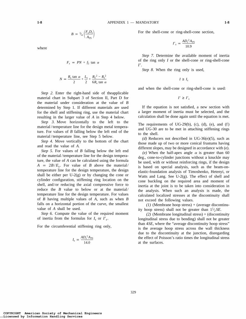
Step 1.Assuming that the shell has been designedand Ds, Ls, and t are known, select a member to beused for the stiffening ring and determine cross-sectionalareaATS. Then calculate factorB using the followingformula. If Fs is a negative number, the design shallbe in accordance with U-2(g):
COPYRIGHT American Society of Mechanical EngineersLicensed by Information Handling ServicesCOPYRIGHT American Society of Mechanical EngineersLicensed by Information Handling Services
ASME B&PVC SEC81$$U85 04-15-00 11:03:52 pd: sec81 Rev 15.03
1-8 APPENDIX 1 — MANDATORY 1-8
B p 3⁄4 1FsDs
ATS2
where
Fs p PN + f2 tan a
N pRs tan a
2+
Ls
2+
RL2 − Rs
2
6Rs tan a
Step 2.Enter the right-hand side of theapplicablematerial chart in Subpart 3 of Section II, Part D forthe material under consideration at the value ofBdetermined by Step 1. If different materials are usedfor the shell and stiffening ring, use the material chartresulting in the larger value ofA in Step 4 below.
Step 3.Move horizontally to the left to thematerial / temperature line for the design metal tempera-ture. For values ofB falling below the left end of thematerial / temperature line, see Step 5 below.
Step 4.Move vertically to the bottom of the chartand read the value ofA.
Step 5.For values ofB falling below the left endof the material / temperature line for the design tempera-ture, the value ofA can be calculated using the formulaA p 2B / Ex. For value of B above the material /temperature line for the design temperature, the designshall be either per U-2(g) or by changing the cone orcylinder configuration, stiffening ring location on theshell, and/or reducing the axial compressive force toreduce the B value to below or at the material /temperature line for the design temperature. For valuesof B having multiple values ofA, such as whenBfalls on a horizontal portion of the curve, the smallestvalue of A shall be used.
Step 6.Compute the value of the required momentof inertia from the formulas forIs or I ′s.
For the circumferential stiffening ring only,
Is pADs
2ATS
14.0
329
[This is electronic file SEC81$$$87 page # 329
For the shell-cone or ring-shell-cone section,
I ′s pADs
2ATS
10.9
Step 7.Determine the available moment of inertiaof the ring only I or the shell-cone or ring-shell-coneI ′.
Step 8.When the ring only is used,
I ≥ Is
and when the shell-cone or ring-shell-cone is used:
I ′ ≥ I ′s
If the equation is not satisfied, a new section witha larger moment of inertia must be selected, and thecalculation shall be done again until the equation is met.
The requirements of UG-29(b), (c), (d), (e), and (f )and UG-30 are to be met in attaching stiffening ringsto the shell.
(d) Reducers not described in UG-36(e)(5), such asthose made up of two or more conical frustums havingdifferent slopes, may be designed in accordance with (e).
(e) When the half-apex anglea is greater than 60deg., cone-to-cylinder junctions without a knuckle maybe used, with or without reinforcing rings, if the designis based on special analysis, such as the beam-on-elastic-foundation analysis of Timoshenko, Hetenyi, orWatts and Lang. See U-2(g). The effect of shell andcone buckling on the required area and moment ofinertia at the joint is to be taken into consideration inthe analysis. When such an analysis is made, thecalculated localized stresses at the discontinuity shallnot exceed the following values.
(1) (Membrane hoop stress) + (average discontinu-ity hoop stress) shall not be greater than 11⁄2SE.
(2) (Membrane longitudinal stress) + (discontinuitylongitudinal stress due to bending) shall not be greaterthan 4SE,where the “average discontinuity hoop stress”is the average hoop stress across the wall thicknessdue to the discontinuity at the junction, disregardingthe effect of Poisson’s ratio times the longitudinal stressat the surfaces.
COPYRIGHT American Society of Mechanical EngineersLicensed by Information Handling ServicesCOPYRIGHT American Society of Mechanical EngineersLicensed by Information Handling Services