ASME Code Considerations for the Compact Heat...
55
ORNL/TM-2015/401 ASME Code Considerations for the Compact Heat Exchanger J. Nestell MPR Associates, Inc. T.-L. Sham Oak Ridge National Laboratory August 31, 2015 Approved for public release; distribution is unlimited.
-
Upload
truongthien -
Category
Documents
-
view
255 -
download
8
Transcript of ASME Code Considerations for the Compact Heat...

ORNL/TM-2015/401
ASME Code Considerations for the Compact Heat Exchanger
J. Nestell MPR Associates, Inc.
T.-L. Sham
Oak Ridge National Laboratory
August 31, 2015
Approved for public release;
distribution is unlimited.

DOCUMENT AVAILABILITY
Reports produced after January 1, 1996, are generally available free via US Department of Energy (DOE) SciTech Connect. Website http://www.osti.gov/scitech/ Reports produced before January 1, 1996, may be purchased by members of the public from the following source: National Technical Information Service 5285 Port Royal Road Springfield, VA 22161 Telephone 703-605-6000 (1-800-553-6847) TDD 703-487-4639 Fax 703-605-6900 E-mail [email protected] Website http://www.ntis.gov/help/ordermethods.aspx Reports are available to DOE employees, DOE contractors, Energy Technology Data Exchange representatives, and International Nuclear Information System representatives from the following source: Office of Scientific and Technical Information PO Box 62 Oak Ridge, TN 37831 Telephone 865-576-8401 Fax 865-576-5728 E-mail [email protected] Website http://www.osti.gov/contact.html
This report was prepared as an account of work sponsored by an agency of the United States Government. Neither the United States Government nor any agency thereof, nor any of their employees, makes any warranty, express or implied, or assumes any legal liability or responsibility for the accuracy, completeness, or usefulness of any information, apparatus, product, or process disclosed, or represents that its use would not infringe privately owned rights. Reference herein to any specific commercial product, process, or service by trade name, trademark, manufacturer, or otherwise, does not necessarily constitute or imply its endorsement, recommendation, or favoring by the United States Government or any agency thereof. The views and opinions of authors expressed herein do not necessarily state or reflect those of the United States Government or any agency thereof.
ORNL/TM-2015/401
Advanced Reactor Technologies Program
ASME CODE CONSIDERATIONS FOR THE COMPACT HEAT EXCHANGER
J. Nestell
MPR Associates, Inc.
T.-L. Sham
Oak Ridge National Laboratory
Date Published: August 31, 2015
Prepared under the direction of the
U.S. Department of Energy
Office of Nuclear Energy
Prepared by
OAK RIDGE NATIONAL LABORATORY
Oak Ridge, TN 37831-6283
managed by
UT-BATTELLE, LLC
for the
US DEPARTMENT OF ENERGY
under contract DE-AC05-00OR22725

Page Intentionally Blank

v
ACKNOWLEDGMENTS
This research was sponsored by the U.S. Department of Energy. Programmatic direction was provided by
the Advanced Reactor Technologies (ART) Program of the Office of Nuclear Energy (NE). We gratefully
acknowledge the support provided by Carl Sink of DOE-NE, ART Program Manager; William Corwin of
DOE-NE, ART Materials Technology Lead; and David Petti of Idaho National Laboratory, ART Co-
National Technical Director.
The authors are grateful to Robert Jetter for helpful discussions. The time spent by Jy-An Wang of Oak
Ridge National Laboratory in reviewing this report is also greatly appreciated.

vi
Page Intentionally Blank

vii
ABSTRACT
The mission of the U.S. Department of Energy (DOE), Office of Nuclear Energy is to advance nuclear
power in order to meet the nation’s energy, environmental, and energy security needs. Advanced high
temperature reactor systems such as sodium fast reactors and high and very high temperature gas-cooled
reactors are being considered for the next generation of nuclear reactor plant designs.
The coolants for these high temperature reactor systems include liquid sodium and helium gas.
Supercritical carbon dioxide (sCO2), a fluid at a temperature and pressure above the supercritical point of
CO2, is currently being investigated by DOE as a working fluid for a nuclear or fossil-heated
recompression closed Brayton cycle energy conversion system that operates at 550˚C (1022˚F) at 200 bar
(2900 psi). Higher operating temperatures are envisioned in future developments. All of these design
concepts require a highly effective heat exchanger that transfers heat from the nuclear or chemical reactor
to the chemical process fluid or to the power cycle.
In the nuclear designs described above, heat is transferred from the primary to the secondary loop via an
intermediate heat exchanger (IHX) and then from the intermediate loop to either a working process or a
power cycle via a secondary heat exchanger (SHX). The IHX is a component in the primary coolant loop
which will be classified as “safety related.” The intermediate loop will likely be classified as “not safety
related but important to safety.” These safety classifications have a direct bearing on heat exchanger
design approaches for the IHX and SHX.
The very high temperatures being considered for the VHTR will require the use of very high temperature
alloys for the IHX and SHX. Material cost considerations alone will dictate that the IHX and SHX be
highly effective; that is, provide high heat transfer area in a small volume. This feature must be
accompanied by low pressure drop and mechanical reliability and robustness. Classic shell and tube
designs will be large and costly, and may only be appropriate in steam generator service in the SHX
where boiling inside the tubes occurs. For other energy conversion systems, all of these features can be
met in a compact heat exchanger design.
This report will examine some of the ASME Code issues that will need to be addressed to allow use of a
Code-qualified compact heat exchanger in IHX or SHX nuclear service. Most effort will focus on the
IHX, since the safety-related (Class A) design rules are more extensive than those for important-to-safety
(Class B) or commercial rules that are relevant to the SHX.

viii
Page Intentionally Blank

ix
CONTENTS
ACKNOWLEDGMENTS ............................................................................................................................ v
ABSTRACT ................................................................................................................................................ vii
LIST OF FIGURES ..................................................................................................................................... xi
ACRONYMS ............................................................................................................................................. xiii
1. INTRODUCTION ................................................................................................................................ 1
2. COMPACT HEAT EXCHANGER DESIGNS .................................................................................... 2 2.1 BRAZED PLATE-FIN HEAT EXCHANGER ......................................................................... 2 2.2 FUSION WELDED FORMED PLATE DESIGNS .................................................................. 4 2.3 UNIT CELL PLATE DESIGNS ............................................................................................... 6 2.4 DIFFUSION BONDED (DIFFUSION WELDED) DESIGNS ................................................ 9
2.4.1 Printed Circuit Heat Exchanger (PCHE) .................................................................... 10 2.4.2 Formed Plate Diffusion Bonded Heat Exchanger ...................................................... 14 2.4.3 Diffusion Bonded, Unit Cell Plate Heat Exchanger ................................................... 15
3. CURRENT CODE STATUS .............................................................................................................. 16
4. DIFFUSION BONDING ISSUES ...................................................................................................... 18
5. MECHANICAL DESIGN APPROACHES FOR MICROCHANNEL HEAT
EXCHANGERS .................................................................................................................................. 21 5.1 ASME BPV CODE SECTION VIII DIVISION 1 .................................................................. 21
5.1.1 Channel Design .......................................................................................................... 21 5.1.2 Header Design ............................................................................................................ 24
5.2 ASME BPV CODE SECTION III .......................................................................................... 24 5.2.1 Section III, Division 5, Subsection HB, Subpart B Design for Class A Service ........ 24 5.2.2 Elastic-Perfectly Plastic Analysis Methodologies ...................................................... 34 5.2.3 Class B Design Rules ................................................................................................. 34 5.2.4 Code Boundaries ........................................................................................................ 34
6. INSPECTION AND TESTS ............................................................................................................... 35
7. FOULING ........................................................................................................................................... 36
8. CONCLUSIONS AND RECOMMENDATIONS ............................................................................. 37 8.1 CONCLUSIONS ..................................................................................................................... 37 8.2 RECOMMENDATIONS ........................................................................................................ 37
9. REFERENCES ................................................................................................................................... 39

x
Page Intentionally Blank

xi
LIST OF FIGURES
Fig. 1. Components of brazed plate fin-heat exchanger. ............................................................................... 2
Fig. 2. Typical flow patterns. ........................................................................................................................ 3
Fig. 3. Braze fillet at a plate-to-fin interface. After Ref 17. Reprinted with permission from Brayton
Energy, LLC. ............................................................................................................................. 4
Fig. 4. Formed plate heat exchanger with welded edges, Tranter Heat Exchangers. Reprinted with
permission from Tranter. ........................................................................................................... 5
Fig. 5. Plate heat exchanger flow paths, Tranter Heat Exchangers. Reprinted with permission from
Tranter. ...................................................................................................................................... 5
Fig. 6. Local channel collapse in plate heat exchanger. ................................................................................ 6
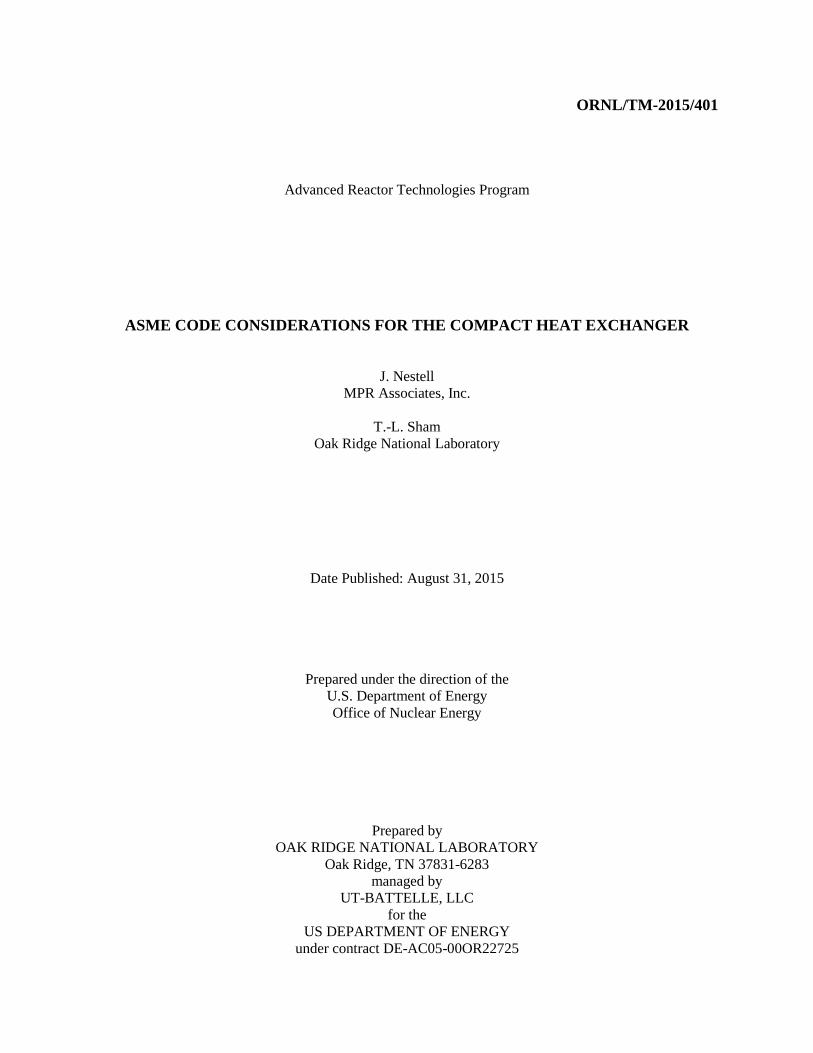
Fig. 7. Unit cell heat exchanger component parts. Reprinted with permission from Brayton Energy,
LLC. .......................................................................................................................................... 7
Fig. 8. Unit cell heat exchanger assembly. Reprinted with permission from Brayton Energy, LLC. ........... 7
Fig. 9. Unit cell heat exchanger crossflow. Reprinted with permission from Brayton Energy, LLC. .......... 8
Fig. 10. Unit cell layer containing high pressure cell and low pressure external fins. .................................. 8
Fig. 11. Unit cell HX in counterflow operation. After Ref 18. Reprinted with permission, ......................... 9
Fig. 12. Diffusion bond recrystallization process. After Ref 1. Reprinted with permission. ...................... 10
Fig. 13. Chemical etch patterns for cross/counterflow PCHE. ................................................................... 11
Fig. 14. (a) Plate stacking for bonding (cross/counterflow) (b) Bonded printed circuit core (cross
flow subsection). After Ref 6. Reprinted with permission. ..................................................... 11
Fig. 15. Bonded section showing complete recrystallization. After Ref 5. Repeated with permission. ..... 11
Fig. 16. Cross flow etching pattern. After Ref 7, Copyright 2010 by the American Nuclear Society,
La Grange Park, Illinois. Reprinted with permission. ............................................................. 12
Fig. 17. Cross/counter flow channel etch pattern. After Ref 7, Copyright 2010 by the American
Nuclear Society, La Grange Park, Illinois. Reprinted with permission. .................................. 12
Fig. 18. Serpentine counter flow etch pattern. After Ref 7, Copyright 2010 by the American Nuclear
Society, La Grange Park, Illinois. Reprinted with permission. ............................................... 12
Fig. 19. (a) Plate stack showing buildup of internal headers. After Ref 7, Copyright 2010 by the
American Nuclear Society, La Grange Park, Illinois. Reprinted with permission. (b)
Finished multi-block heat exchanger containing external “D” headers and internal
ported headers. After Ref 8, Copyright 2009 by the American Nuclear Society, La
Grange Park, Illinois. Reprinted with permission. .................................................................. 13
Fig. 20. Multi-block core during fabrication. After Ref 7, Copyright 2010 by the American Nuclear
Society, La Grange Park, Illinois. Reprinted with permission. ............................................... 13
Fig. 21. (a) Section VIII U-Stamp PCHE with cross/counter flow configuration shown in Fig. 14a.
After Ref 5. Reprinted with permission. (b) Configuration of flows and headers for
cross/counter flow configuration in Fig. 14a. .......................................................................... 14
Fig. 22. Finished multiblock heat exchanger showing headers. After Ref 7, Copyright 2010 by the
American Nuclear Society, La Grange Park, Illinois. Reprinted with permission. ................. 14

xii
Fig. 23. Close-up views of diffusion-bonded formed plate (left) and printed circuit (right) channels.
Arrows indicate loads perpendicular and parallel to the bond joint. After Ref 7,
Copyright 2010 by the American Nuclear Society, La Grange Park, Illinois. Reprinted
with permission. ...................................................................................................................... 15
Fig. 24. Composite heat exchanger core with alternating layers of etched and formed plate channels.
After Ref 7, Copyright 2010 by the American Nuclear Society, La Grange Park,
Illinois. Reprinted with permission. ........................................................................................ 15
Fig. 25. Diffusion bond showing residual particles (probably oxides). After Ref 11. Reprinted with
permission from Elsevier. ........................................................................................................ 20
Fig. 26. Properly bonded core (crossflow section). After Ref 9, Copyright 2008 by the American
Nuclear Society, La Grange Park, Illinois. Reprinted with permission. .................................. 21
Fig. 27. Schematic of etched channel design (above) and simplified rectilinear model (below). After
Ref 6. Reprinted with permission. ........................................................................................... 22
Fig. 28. Thick-walled cylinder model for sizing t2. .................................................................................... 23
Fig. 29. Major components of the compact heat exchanger. ...................................................................... 25
Fig. 30. (a) Finite element model of etched channels in a hydrogen cooler with pressure on one side
only. (b) Pressure stresses in channel. Peaking in “D” corner is observed, but corner
radius is expected to be much smaller (higher peak stresses) in actual microchannel
designs. After Ref 5. Reprinted with permission. ................................................................... 26
Fig. 31. Thermal stress field near core/sidewall interface. ......................................................................... 28
Fig. 32. Complex thermal /mechanical interactions at header locations during core cooling
transients. ................................................................................................................................. 29
Fig. 33. (a) through (i) show the design of compact heat exchanger modules inside a Section III
vessel. After Ref 13. ................................................................................................................ 30
Fig. 34. Model suggested here for calculating areal density of channels. ................................................... 32
Fig. 35. Principal axes for identifying orthotropic properties. .................................................................... 32
Fig. 36. Channel array finite element model for calculating localized stresses in channel walls. After
Ref 16. ..................................................................................................................................... 33

xiii
ACRONYMS
ASME American Society of Mechanical Engineers
BPV boiler and pressure vessel
DFW diffusion welding
DOE Department of Energy
FPHE formed plate heat exchanger
HTGR high temperature gas-cooled reactor
HX heat exchanger
IHX intermediate heat exchanger
INL Idaho National Laboratory
MIT Massachusetts Institute of Technology
NDE non destructive examination
NGNP next generation nuclear plant
PCHE printed circuit heat exchanger
PFHE plate-fin heat exchanger
R&D research and development
sCO2 supercritical carbon dioxide
SFR sodium fast reactor
SHX secondary heat exchanger
UCHE unit cell heat exchanger
VHTR very high temperature reactor
VPE Vacuum Process Engineering

xiv
Page Intentionally Blank

1
1. INTRODUCTION
The mission of the U.S. Department of Energy (DOE), Office of Nuclear Energy is to advance nuclear
power in order to meet the nation’s energy, environmental, and energy security needs. Advanced high
temperature reactor systems are being considered for the next generation of nuclear reactor plant designs.
Sodium Fast Reactor (SFR), with an outlet temperature of 550ºC (1022ºF), is a leading candidate for
several possible missions, including recycling of used fuel for closing the fuel cycle and for power
generation. Other reactor systems considered are high and very high temperature gas-cooled reactors
(HTGRs and VHTRs), with core outlet temperatures in the range of 750 to 950˚C (1382 to 1742˚F), to
support high temperature chemical processes such as hydrogen production and for power generation.
The coolants for these high temperature reactor systems include liquid sodium and helium gas.
Supercritical carbon dioxide (sCO2), a fluid at a temperature and pressure above the supercritical point of
CO2, is currently being investigated by DOE as a working fluid for a nuclear or fossil-heated
recompression closed Brayton cycle energy conversion system that operates at 550˚C (1022˚F) at 200 bar
(2900 psi). Higher operating temperatures are envisioned in future developments. All of these design
concepts require a highly effective heat exchanger that transfers heat from the nuclear or chemical reactor
to the chemical process fluid or to the power cycle.
The nuclear designs described above most often contain a primary coolant loop that is heated by the
reactor core and an intermediate loop containing a similar coolant operating at a similar pressure. Heat is
transferred from the primary to the secondary loop via an intermediate heat exchanger (IHX). Thus, the
IHX can be a liquid-to-liquid (e.g., sodium-to-sodium) or gas-to-gas (e.g., helium-to-helium) design.
Transfer of heat from the intermediate loop to the working process (e.g., to the sulfur–iodine hydrogen
generation process) or to the power cycle (e.g., sodium-to-sCO2 for a Brayton cycle) is accomplished by a
secondary heat exchanger (SHX) that can be a gas-to-gas or liquid-to-fluid design. The IHX is a
component in the primary coolant loop which will be classified as “safety related.” The intermediate loop
will likely be classified as “not safety related but important to safety.” These safety classifications have a
direct bearing on heat exchanger design approaches for the IHX and SHX.
The very high temperatures being considered for the VHTR will require the use of very high temperature
alloys for the IHX and SHX. Material cost considerations alone will dictate that the IHX and SHX be
highly effective; that is, provide high heat transfer area in a small volume. This feature must be
accompanied by low pressure drop and mechanical reliability and robustness. All of these features can be
met in a compact heat exchanger design.
Classic shell and tube designs will be large and costly, and may only be appropriate in steam generator
service in the SHX where boiling inside the tubes occurs. Potential steam quality issues associated with
boiling and slug flow in the small flow channels in a compact heat exchanger, along with likely corrosion
product fouling problems in those channels, may eliminate the compact heat exchanger from
consideration for steam generator service.
This report will examine some of the ASME Code issues that will need to be addressed to allow use of a
Code-qualified compact heat exchanger in IHX or SHX nuclear service. Most effort will focus on the
IHX, since the safety-related (Class A) design rules are more extensive than those for important-to-safety
(Class B) or commercial rules that are relevant to the SHX.

2
2. COMPACT HEAT EXCHANGER DESIGNS
DOE is currently considering several compact heat exchanger designs for the SHX of high temperature
reactor systems. They include (Reference 1):
Brazed plate-fin heat exchanger (PFHE)
Fusion bonded formed plate heat exchanger (FPHE)
Fusion bonded unit cell heat exchanger (UCHE)
Fusion bonded printed circuit heat exchanger (PCHE)
2.1 BRAZED PLATE-FIN HEAT EXCHANGER
The traditional brazed plate-fin heat exchanger is built up from partition plates, formed fins, and side bar
material, as shown in Fig. 1.
Fig. 1. Components of brazed plate fin-heat exchanger.
These layers are then built up to accommodate various flow patterns like counter flow, cross flow, etc.,
depending on thermal hydraulic design requirements. This is shown in Fig. 2.

3
Fig. 2. Typical flow patterns.
The heat exchanger is fabricated from a stack of alternating fluid A and fluid B layers which are then
brazed together.
The plate-fin heat exchanger geometry has several nice features, as follows:
It is very efficient from both a materials and thermal standpoint.
It can handle moderately high pressures.
Depending on the base metal and braze alloy, it can handle high temperatures.
It can be made with relatively large channels to provide a low pressure drop in viscous fluids
like liquid sodium.
On the other hand, the brazed plate-fin heat exchanger has limitations or vulnerabilities that would make
it unsuitable for nuclear safety class service, as follows:
The creep, fatigue and toughness of the braze joint is dependent on the braze alloy properties
and brazing process control, not just the base metal properties. The braze alloy properties
will likely be limiting for very high temperature service.
Braze quality will depend on brazing process controls and surface preparation (cleaning).
There is poor inspectability of brazes within the core.
Joint strength and ductility also depend strongly on process controls for fin-to-partition-plate
fit up, which can vary due to fin height and flatness variations. Controlling these requires
tight control on fin rolling and forming processes.
Depending on strength, ductility and strain hardening properties, some high temperature
alloys like the nickel base super alloys may not be suitable for the fin forming operation.
The melting temperature suppressant element in the braze alloy (typically, P or B in the
nickel brazes) can produce brittle second phases in the braze itself (e.g. NiP) or in the base
metal by diffusion (MoP, MoP3, or CrB in Alloy 617, for example), Reference 2.

4
The as-brazed heat exchanger structure contains very high residual stresses that can cause
fin-to-partition plate cracking, Reference 3. These cracks can easily go undetected and could
be the initiators for premature fatigue or creep failures. The presence of as-brazed residual
stresses requires that a post-braze stress relief be performed.
The core structure is very rigid and subject to high thermal stresses if temperature gradients
or transients are severe. Thermal stresses are likely to be limiting for large solid core
designs.
The peak operating stresses in the fin-to-plate joint depend on the braze fillet radius, which
can be quite variable since it depends on fit up, volume of braze alloy, fin flatness, etc. See
Fig. 3. It would be difficult to perform an analytic fatigue or creep evaluation of the joint
because of the potential geometric variability and the resulting variability in peak stresses.
Fig. 3. Braze fillet at a plate-to-fin interface. After Ref 17. Reprinted with permission from Brayton Energy,
LLC.
The process control uncertainties combined with the inability to inspect the majority of braze joints in a
brazed plate-fin heat exchanger design probably make this design unsuitable for safety grade nuclear
service. These are the unknown creep properties of the braze alloy at very high temperatures, the potential
for base metal embrittlement at the joint interface, the indeterminate geometry of individual braze fillets,
and potentially large thermal stresses in the rigid core during thermal transients or flow maldistributions
conditions.
2.2 FUSION WELDED FORMED PLATE DESIGNS
There are a number of fusion welded compact heat exchanger designs that avoid braze quality and
thermal stress problems described above. These are relatively low pressure formed plate designs where
the “fins” are “herringbone” corrugations in the partition plates themselves. These designs incorporate
the inlet and outlet headers in the plate stock itself. Some plate designs are shown in Fig. 4, and the flow
and header arrangements are shown in Fig. 5.

5
Fig. 4. Formed plate heat exchanger with welded edges, Tranter Heat Exchangers. Reprinted with permission
from Tranter.
Fig. 5. Plate heat exchanger flow paths, Tranter Heat Exchangers. Reprinted with permission from Tranter.
The most limiting feature of the welded plate design is its inability to support high delta-P fluid
conditions. The welding is limited to the plate edge and manifolds, leaving the middle of each plate
unsupported for pressure loads. Pressure loads are usually resisted by a strong back or frame supporting
the entire core, but some internal support can be obtained by local spot or plug welds between the
partition plates in the center area in “quilted” or “dimpled” plate designs. But even if the stack is
supported by a strong back or cage, under high delta-P fluid conditions, individual herringbone
convolutions are subject to pressure loading which could lead to local herringbone collapse by creep
deformation at high temperatures, ultimately choking off of the low pressure layers in the stack. See Fig.
6, below.

6
Fig. 6. Local channel collapse in plate heat exchanger.
Heatric notes in Reference 4, that, “The combination of low design strength (probably less than 10 MPa at
temperature) and relatively high design pressure (as a percent of design stress) will… limit the type of
plate heat exchanger. Edge welded plate or any exchanger type with large unsupported areas will be
mechanically unacceptable.” We note that, while this may be true under high delta-P fluid applications,
there are IHX applications with low pressure on both sides where simple edge-welded plate designs may
be applicable., An example is a sodium-to-sodium heat exchange to an intermediate loop Plate type
designs supported only on the edges are highly attractive for solving thermal stress problems since the
layers cannot support any in-plane shear stresses except at welds, resulting in low thermal stresses over
much of the plate area.
2.3 UNIT CELL PLATE DESIGNS
A rather different plate design approach has been taken by Ingersoll-Rand for gas turbine recuperators
which can handle moderately high temperatures and moderate delta-Ps and still operate with low thermal
stresses. This concept is being considered for recuperator service in the sCO2 plant cycle and for the IHX
in NGNP, as described in References 17 and 18.
The original Ingersoll-Rand recuperator design concept is a brazed plate/fin heat exchanger operating in
cross flow with open low pressure side edges. In this design, the high pressure (primary) compressor air
is heated by low pressure turbine exhaust. The Ingersoll-Rand design is in use in commercial and military
gas turbine recuperators to heat compressor air. They can handle moderately high temperatures and
pressures, 530C and a delta-P of 1.5MPa. The design is especially robust against demanding temperature
transients.
The nuclear applications for the unit cell heat exchanger are proposed to be counter flow designs as
shown in Fig. 7, Fig. 8 and Fig. 9 below.
7
3
Unit-Cell ConstructionExploded View
Fig. 7. Unit cell heat exchanger component parts. Reprinted with permission from Brayton Energy, LLC.
2
Cutaway Fin-Fin Core
• Cells welded at rings only
• Slip-plane at adiabatic
boundary between LP fins
Fin-Fin
Unit-Cell
Unit- Cell Cut
Away
Unit-Cell Construction
Fig. 8. Unit cell heat exchanger assembly. Reprinted with permission from Brayton Energy, LLC.
(cross flow)

8
4
Unit-Cell ConstructionFlow Orientations
Fig. 9. Unit cell heat exchanger crossflow. Reprinted with permission from Brayton Energy, LLC.
The cells layers are connected by brazing or welding only at the high pressure manifolds shown above.
This produces a stack of cells with much higher internal flexibility than the solid core described in
Section 2.1.
The key to the design is the unit cell which consists of two partition plates supporting a single corrugated,
high pressure cell fin row. Secondary side fins are brazed or bonded to the outside of the partition plates.
The partition plates and pressure cell fin row are brazed or otherwise bonded to form a single layer, high-
pressure cell with attached secondary side fins. Pressure can be supported within the pressure cell layer
without the aid of a strong back or cage. A single unit cell layer is shown in Fig. 10, below.
Fig. 10. Unit cell layer containing high pressure cell and low pressure external fins.
For a nuclear Brayton cycle, the working fluid might be high pressure (~9 MPa), high temperature (800-
950C) helium. Normally, the delta-P between the primary and intermediate (secondary) loops is
relatively small, about 0.5 MPa. But the unit cell design allows the heat exchanger to a handle loss-of-
pressure transient in the secondary loop without primary rupture under the resulting high delta-P

9
conditions. This capability is required by the Code (loss of pressure on one side) and which is unlikely to
be achieved in simple edge-welded plate designs. The unit cell design concept might even be a good
candidate for low pressure to high pressure heat exchange such as might be needed for a liquid sodium to
high pressure fluid (sCO2 Brayton cycle) plant. The sodium would occupy the secondary (low pressure)
layers in the design, and the fluid the high pressure cell layers.
Some means must be provided for supporting the secondary pressure, and a means must be provided to
seal the secondary side edges outside of the secondary inlets and outlets so as to direct the secondary flow
over the plates in a counter flow direction, rather than the cross flow used by Ingersoll-Rand. This is
shown in Fig. 11. Consequently, it appears the heat exchanger will require a containment vessel for the
secondary gas or liquid and welded edges on portions of the cell-to-cell secondary side layers. A concave
canopy type seal would probably be suitable to seal portions of the secondary side edges for counter flow
operation while providing some cell-to-cell edge flexibility. We note the pressure cell flexibility could be
further increased by periodically interrupting corrugated fin sections. Fin sections could also be
periodically offset one-half the fin pitch to increase mixing (and pressure drop) and reduce thermal
gradients due to flow maldistributions.
Fig. 11. Unit cell HX in counterflow operation. After Ref 18. Reprinted with permission,
As noted earlier, the Ingersoll-Rand service experience has been with brazed unit cell designs. The
fabrication, inspection, and potential creep limitations of brazed designs described earlier in Section 2.1
affect this design as well, so another method of cell bonding will likely be required for nuclear service.
Achieving higher pressures and Code certification may require going with diffusion bonded (i.e. welded)
plate/fin structures and conventionally welded high pressure manifold layers. This bonding method is
described in Section 2.4.
2.4 DIFFUSION BONDED (DIFFUSION WELDED) DESIGNS
A relatively recent development in compact heat exchanger design is the diffusion bonded (also referred
to as “diffusion welded”) printed circuit and formed plate design. Research interest in diffusion bonded
heat exchangers for nuclear service has been high, and recent ASME Code activities have focused on the
endorsement of diffusion bonding as a Code-approved heat exchanger joining technique. Heatric has had
the most experience manufacturing diffusion bonded designs and holds an ASME Section VIII “U” stamp
for their production. Other manufacturers, such as Vacuum Process Engineering (VPE) and Velocys are
also developing diffusion bonded heat exchangers, and the VPE work is in collaboration with the Sandia
National Laboratories for potential nuclear applications. Kobe Steel in Japan has also investigated
diffusion bonding and has fabricated at least one U-stamped, stainless steel PCHE using this method. See
Fig. 15a which was taken from Reference 5.
Primary
OutPrimary In
Secondary In Secondary Out

10
Diffusion bonding is a solid state welding process that bonds two contacting surfaces (faying surfaces)
through the application of heat and pressure in a vacuum. The process is performed at elevated
temperatures but below the melting point and at moderate pressure (5-10 MPa or 700-1400 psi). The
faying surfaces merge by a diffusion process as shown in Fig. 12.
Fig. 12. Diffusion bond recrystallization process. After Ref 1. Reprinted with permission.
In contrast to brazed joints where the braze alloy and its interaction with the base material affects joint
strength, creep, and fatigue properties, the diffusion bonded joint is advertised to have base metal
properties.
2.4.1 Printed Circuit Heat Exchanger (PCHE)
Diffusion bonding has facilitated the development of highly effective (high rate of heat exchange per unit
volume) printed circuit heat exchanger designs with heat transfer surface-to-volume ratios (areal
densities) approaching 2500 m2/m
3, Reference 1. Since the diffusion bonded designs being considered
are relatively new compared to the plate-fin and formed plate designs described in Sections 2.1, 2.2 and
2.3, some effort will be expended here to describe this heat exchanger. In this design, the flow channels
are chemically etched into the partition plates themselves, and the plates are stacked and diffusion bonded
to form the heat exchanger. This is shown in Fig. 13 and Fig. 14.

11
Fig. 13. Chemical etch patterns for cross/counterflow PCHE.
(a) (b)
Fig. 14. (a) Plate stacking for bonding (cross/counterflow) (b) Bonded printed circuit core (cross flow
subsection). After Ref 6. Reprinted with permission.
Once bonded, the heat exchanger becomes a monolithic block of metal since the weld fusion line between
plates disappears as the grain structure recrystallizes during the diffusion process (See Fig. 12). The cross
section of an actual bonded assembly is shown in Fig. 15, which shows typical semicircular etched
channels and the bond area between the plates.
Fig. 15. Bonded section showing complete recrystallization. After Ref 5. Repeated with permission.
Heatric, Reference 7, shows various flow patterns that can be produced in the etched plates. For example:
Counter flow with cross flow on the ends (as shown in Fig. 13 and Fig. 14)
Simple cross flow (Fig. 16)
Cross-counter flow (Fig. 17)
Serpentine counter flow (Fig. 18)

12
Fig. 16. Cross flow etching pattern. After Ref 7, Copyright 2010 by the American Nuclear Society, La Grange
Park, Illinois. Reprinted with permission.
Fig. 17. Cross/counter flow channel etch pattern. After Ref 7, Copyright 2010 by the American Nuclear
Society, La Grange Park, Illinois. Reprinted with permission.
Fig. 18. Serpentine counter flow etch pattern. After Ref 7, Copyright 2010 by the American Nuclear Society,
La Grange Park, Illinois. Reprinted with permission.
In some cases, internal porting can be designed into the plate stock by etching completely through the
plates or headers, as shown in Fig. 19, similar to what is done for embossed plate laminae like those
shown in Fig. 4.

13
(a) (b)
Fig. 19. (a) Plate stack showing buildup of internal headers. After Ref 7, Copyright 2010 by the American
Nuclear Society, La Grange Park, Illinois. Reprinted with permission. (b) Finished multi-block heat
exchanger containing external “D” headers and internal ported headers. After Ref 8, Copyright 2009
by the American Nuclear Society, La Grange Park, Illinois. Reprinted with permission.
The PCHE channels are roughly semi-circular and can vary in depth (depending on design) from about
0.1mm to 2.5mm, but only the larger channels will be of practical interest for power service. The
unetched ridges between channels form the “fins”. Fin thickness depends on design pressure, allowable
stress at temperature, and channel etch depth. The channel “wall” is the remaining unetched material
above and below the channels. It is influenced by the channel width. Side and end margins, shown in
Fig. 7, become the side walls of the diffusion welded block. The stack ends are the unetched plates above
and below the etched stack which form solid end walls once the stack is diffusion bonded. Currently,
Heatric can manufacture blocks with dimensions up to 0.6m x 0.6m x 1.5m, Reference 6. If larger heat
exchangers are required, multiple blocks can be welded together, as shown in Fig. 20, taken from
Reference 7.
Fig. 20. Multi-block core during fabrication. After Ref 7, Copyright 2010 by the American Nuclear Society,
La Grange Park, Illinois. Reprinted with permission.
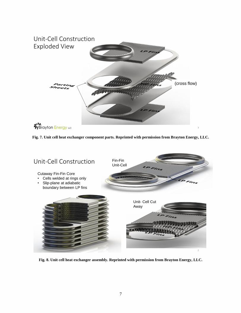
PCHE blocks will usually have headers, nozzles, and flanges, as shown in Fig. 21 for a single block, and
in Fig. 20 and Fig. 22 for a multiple block design.
14
(a) (b)
Fig. 21. (a) Section VIII U-Stamp PCHE with cross/counter flow configuration shown in Fig. 14a. After Ref 5.
Reprinted with permission. (b) Configuration of flows and headers for cross/counter flow
configuration in Fig. 14a.
Fig. 22. Finished multiblock heat exchanger showing headers. After Ref 7, Copyright 2010 by the American
Nuclear Society, La Grange Park, Illinois. Reprinted with permission.
2.4.2 Formed Plate Diffusion Bonded Heat Exchanger
The formed plate heat exchanger offers large channel size and material economy over the printed circuit
approach, Reference 7. The construction is similar to the plate-fin brazed design shown in Fig. 1 but the
core is diffusion bonded, rather than brazed. This design is useful for lower pressure applications like a
sodium service. For high pressure applications like helium primary loop to helium intermediate loop, the
printed circuit design is more suitable, at least from a primary stress standpoint. For service between low
and high pressure systems like the sodium/sCO2 SHX, a composite design can be used that is fabricated
from alternating formed plate and printed circuit laminae.
A close-up view of the formed plate and printed circuit channels is shown in Fig. 23, from Reference 8.
(As will be discussed in later sections, loads applied perpendicular to the weld joint must be evaluated
based on a weld joint efficiency factor that is applied to the allowable stress.) A core containing both
printed circuit and formed plate channels (composite heat exchanger) is shown in Fig. 24.

15
Fig. 23. Close-up views of diffusion-bonded formed plate (left) and printed circuit (right) channels. Arrows
indicate loads perpendicular and parallel to the bond joint. After Ref 7, Copyright 2010 by the
American Nuclear Society, La Grange Park, Illinois. Reprinted with permission.
Fig. 24. Composite heat exchanger core with alternating layers of etched and formed plate channels. After
Ref 7, Copyright 2010 by the American Nuclear Society, La Grange Park, Illinois. Reprinted with
permission.
2.4.3 Diffusion Bonded, Unit Cell Plate Heat Exchanger
The unit cell plate heat exchanger design described in Section 2.3 can be adapted to diffusion bonding
methods described for the composite heat exchanger design above. The “stack” for diffusion welding
would consist of a single pressure cell with internal fins and its attached secondary fins.
Perpendicular
Parallel
16
3. CURRENT CODE STATUS
Vacuum brazed plate-fin heat exchangers are covered by design rules in the ASME Code, Section VIII,
Division 1 (U, U2, R stamps) along with Section IX weld procedure and welder qualification
requirements for brazing. The strength properties of the braze alloy limit the upper temperature at which
these designs can be used, and the basic plate-fin geometry limits service to moderate pressures. For
those reasons and as noted earlier, the brazed designs are not being considered for high temperature
nuclear service.
Edge-welded plate heat exchangers have long been part of the Section VIII of the ASME Boiler and
Pressure Vessel Code.
Diffusion bonding (or diffusion welding) was added to the allowed Section IX welding processes (“DFW”
welding) in the 2011 Addenda. Requirements for the diffusion bonding of microchannel heat exchangers
were outlined in Code Case 2437-1 in 2005 and were incorporated directly in Section VIII, Division 1 in
2011 (in enhanced form) as Mandatory Appendix 42. The Appendix specifies bonding procedures and
performance qualification tests. These are similar to the DFW requirements in Section IX.
Design, fabrication and inspection requirements for diffusion bonded microchannel heat exchangers were
provided in 2009 in Code Case 2621-1. There are restrictions in the Code Case, as follows:
The alloys for construction are limited to:
SA 240, Type 304L stainless steel
SA 240, Type 316L stainless steel
SA 240, 2205 stainless steel.
Bi-metallic bond joints between dissimilar alloys are prohibited.
The vessels cannot be used for “lethal service;” that is, in service containing lethal substances.
The alloys listed in Code Case 2621-1 are not the same as those allowed for Class A construction in
Section III, Division 5. Relevant alloys for high temperature reactor heat exchanger service that are
already in Division 5 are Type 304H and 316H stainless steels and Alloy 800H. None of the alloys in
Code Case 2621-1 or in Division 5 can achieve the high temperature, long service life requirements for
the hottest applications of the IHX, but Alloy 800H comes closest.
Based on reviews conducted by Heatric for candidate alloys for very high temperature service,
Reference 10, nickel base Alloys 617 and 230 would be the top candidates for IHX and SHX service.
This is consistent with the conclusions of DOE, and a DOE effort to qualify Alloy 617 for Section III,
Division 5 applications is on-going.
The “lethal service” restriction may apply to the IHX and SHX. This is certainly true for the beryllium-
containing molten salts being considered as a reactor coolant, and it may apply to molten sodium or lead-
bismuth alloys. But getting past this restriction may be simplified if a design can be qualified for nuclear
safety related service in the first place.
Heatric currently holds a U-stamp for diffusion bonded microchannel heat exchangers, and Kobe Steel in
Reference 5 describes a stainless steel PCHE with a U-stamp they produced. It is shown in Fig. 21a.
Heatric has produced an Alloy 617 printed circuit heat exchanger for INL testing. The authors understand
that Sandia National Laboratories is working with Vacuum Process Engineering in California to produce

17
a printed circuit Alloy 617 heat exchanger, and Velocys in Texas is considering a U-stamp for diffusion
bonded heat exchanger designs.

18
4. DIFFUSION BONDING ISSUES
The successful incorporation of the diffusion bonded compact heat exchanger in high temperature in
Class A or Class B nuclear service relies on the ability of the manufacturer to consistently and reliably
produce core stacks with high quality diffusion welds. Since it is impractical to inspect each of the
hundreds of thousands of welds in a core stack, component quality will depend on a good understanding
of the essential welding variables and their strict control.
As touched upon earlier, diffusion bonding is a solid state joining process that uses moderate contact
pressure between surfaces at a high temperature in a vacuum or controlled atmosphere to promote atom
diffusion across the interface. A successful bond undergoes recrystallization of grains at the bond
interface. If the process is carefully controlled, the diffusion bonded joint achieves base material
properties. Some of the welding parameters for diffusion bonding are kept proprietary by the
manufacturers, but some obvious ones include time, pressure, temperature and atmosphere.
The specific Section IX DFW welding “essential variables” controlled during weld procedure
qualification are listed in Section IX and in Section VIII, Appendix 42. They include the following:
Material grade
Material sheet finish (smoothness)
Material surface preparation
Bonding temperature and time
Bonding atmosphere
Block compression (i.e. pressure)
Post-bond heat treatment
Since little is publicly known about details of the process controls required in each of these areas, some
effort by DOE/ASME to independently understand the diffusion bonding process is warranted, especially
for some of the newer nickel base super alloys like Alloy 617. A summary of the current public
understanding of the essential variables is presented in Reference 1. A few important observations from
that reference are as follows:
Material thermodynamics – The thermodynamics of the base metal (melting point, creep rate,
recrystallization dynamics) will determine the required temperature, pressure and time for bonding.
Material chromium content – Corrosion resistant materials like the stainless steels, Alloy 800 and
the nickel base super alloys like Alloy 617 contain high levels of chromium (>15%) as an alloying
element. Chromium forms a protective oxide at ambient temperatures and above that provides
corrosion resistance. Unfortunately, this oxide is not very soluble in the base metal, and it inhibits
diffusion and recrystallization at the bond interface. Even if the oxide is stripped off in a pickling
bath prior to bonding, sheet surfaces quickly re-oxidize in the high temperature vacuum press
environment which usually contains residual water vapor. One key to successful diffusion bonding
of these alloys is the method used to control chromium oxides.
Surface preparation – A common technique for protecting surfaces from oxidation is to electroplate
a thin (~1μm) nickel layer on sheet surfaces after they have been stripped of oxides by pickling or

19
by reverse polarization of the plating electrodes. The nickel oxides that form on the plated nickel
surface are soluble in the nickel and the underlying base metal and diffuse away from the joint
interface during bonding. Eventually, the nickel itself diffuses into the parent material and
disappears, as reported in Reference 1.
Surface finish – The smoothness of the plate surface affects the local contact area in the bond and
the height of asperities that must be absorbed during the bonding process (see Fig. 12). This in
turn, affects the required stack compression and the time required for joining without producing
residual voids.
Stack compression – The required pressure to make a diffusion bond depends on surface finish, as
noted above, the temperature used for bonding and the base metal primary creep rate at that
temperature and pressure. The formed plate designs used in composite heat exchangers will require
sufficient pressure to evenly contact all formed fin tops in a layer during the bonding process, and
these can vary slightly in height and fin top flatness. At the same time, too much pressure could
buckle the fins due to creep.
Current DFW procedure and performance qualification requirements specify that mechanical tests be
performed on diffusion bonded blocks containing unetched (no channels) laminae of the standard sheet
material used in the welding. Some reduction in strength is expected after bonding due to the reduction in
cold work dislocation density at the bonding temperature. This was reported by Heatric in Reference 8 for
316L stainless steel sheet, but minimum Code mechanical properties and creep strength were still met
after bonding. Similar results were observed by Kobe Steel in Reference 5. Preliminary work by Heatric
on Alloy 617, reported in Reference 12, suggests the alloy still meets Code minimum properties after the
bonding thermal cycle.
The bonding process involves heating to above 1000˚C, which creates the potential for recrystallization of
the entire cross section, not just at the bond line. Gross recrystallization will more dramatically affect the
mechanical, fatigue and creep properties of the bonded stack. Since the sheet material will likely be cold
finished at the mill to meet stringent thickness and surface finish requirements, it will likely undergo a 5-
20% cold reduction pass as a finishing operation. Because of the cold work, rapid grain growth during
bonding is possible, producing a coarse microstructure which has a negative impact on strength, creep
strength and resistance to cyclic fatigue. Care must be taken to avoid cold finishing levels in the sheet
stock that could lead to excessive grain growth during bonding process.
Finally, there has been recent work reported in the literature regarding the use of “transient liquid phase”
brazing for compact heat exchangers, Reference 2. In this method the core is brazed with a nickel-
phosphorous or nickel-boron braze alloy which melts at a relatively low temperature. The liquid braze
alloy fills in asperities and promotes diffusion at the bond line. Under pressure and long hold times, the
braze alloy eventually diffuses and dilutes into the base metal leaving a diffusion bond with no remaining
braze alloy.
It is tempting to consider using an electroless nickel plating on the lamina sheets as a method to apply the
braze alloy and also to prevent chromium oxide formation. Electroless nickel coatings can be made with
the 9-11% phosphorous levels used in braze alloys. Unfortunately, in the work reported in Reference 2,
the phosphorous was found to produce high levels of nickel and molybdenum phosphides in Alloy 617
near the bond line. The rate of diffusion of the phosphorous was slow and phosphorous levels stayed high
near the bond line. This produced an inhomogeneous microstructure with unknown strength, creep and
fatigue properties. Because of this, the use of electroless nickel containing high phosphorous levels
cannot be recommended.
It is not clear from a review of the open literature if sufficient public understanding of the diffusion bond
(DFW weld) essential variables exists to accept this method for nuclear service. As a case in point, in

20
recent work at the Ohio State University there were bond failures in mechanical property test specimens
removed from an Alloy 617 bond stack, Reference 11. The bonds showed evidence of oxide
contamination and had low strength and no ductility. A bond cross section from the stack is shown in
Fig. 25, taken from Reference 11. The authors reported that the stack sheets had been nickel
electroplated, but this was obviously insufficient to control oxides. Clearly, more work needs to be done
to determine how the diffusion bonding process can be made robust and able to accept variations in the
essential variables described above, and maybe others. This work is required to build confidence in the
DFW process and should be published in the open literature for peer review and potential incorporation in
the Section III rules.
Fig. 25. Diffusion bond showing residual particles (probably oxides). After Ref 11. Reprinted with permission
from Elsevier.

21
5. MECHANICAL DESIGN APPROACHES FOR MICROCHANNEL HEAT EXCHANGERS
5.1 ASME BPV CODE SECTION VIII DIVISION 1
Code Case 2621-1 allows the construction of diffusion bonded microchannel heat exchangers to
Section VIII, Division 1 rules, but with restrictions on the materials of construction and the limitation of
applicability to non-lethal service, as described earlier. Heatric provides a detailed description of their
mechanical design process for the channels and headers in Reference 6. The process is based on the rules
for non-circular vessels in Mandatory Appendix 13. MIT, Reference 13 and INL, References 1 and 14,
have published channel designs based on the method of Hesselgreaves which is mathematically
equivalent to the Heatric method for determining the channel pitch but differs from that approach for
determining the total thickness of the etched plate. A brief description of these “design by rule”
approaches is provided below.
Note: Extensive work has been done on the thermal performance of the heat exchangers, as well, but this
work is not ASME Code related and will not be discussed in this paper. See References 1, 6 and 14 for
examples of thermal performance calculations for compact heat exchangers.
The mechanical design of a printed circuit heat exchanger (PCHE) consists of setting the dimensions of
the various components shown in Fig. 14, as follows:
Unmilled ridge width between channels (influenced by the channel depth and plate gauge)
Plate gauge (influenced by the channel depth and width)
Side margins (influenced by header thickness and the attachment welds)
End margins (influenced by header thickness and the attachment welds)
Block ends (influenced by the thickest of the headers)
5.1.1 Channel Design
A printed circuit heat exchanger block contains numerous channels embedded in a solid matrix. A
micrograph of a block cross section is shown in Fig. 26.
Fig. 26. Properly bonded core (crossflow section). After Ref 9, Copyright 2008 by the American Nuclear
Society, La Grange Park, Illinois. Reprinted with permission.
22
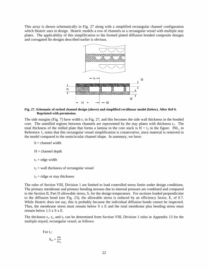
This array is shown schematically in Fig. 27 along with a simplified rectangular channel configuration
which Heatric uses in design. Heatric models a row of channels as a rectangular vessel with multiple stay
plates. The applicability of this simplification to the formed plated diffusion bonded composite designs
and corrugated fin designs described earlier is obvious.
Fig. 27. Schematic of etched channel design (above) and simplified rectilinear model (below). After Ref 6.
Reprinted with permission.
The side margins (Fig. 7) have width t1 in Fig. 27, and this becomes the side wall thickness in the bonded
core. The unmilled regions between channels are represented by the stay plates with thickness t3. The
total thickness of the milled plate that forms a lamina in the core stack is H + t2 in the figure. INL, in
Reference 1, notes that this rectangular vessel simplification is conservative, since material is removed in
the model compared to the semicircular channel shape. In summary, we have:
h = channel width
H = channel depth
t1 = edge width
t2 = wall thickness of rectangular vessel
t3 = ridge or stay thickness
The rules of Section VIII, Division 1 are limited to load controlled stress limits under design conditions.
The primary membrane and primary bending stresses due to internal pressure are combined and compared
to the Section II, Part D allowable stress, S, for the design temperature. For sections loaded perpendicular
to the diffusion bond (see Fig. 23), the allowable stress is reduced by an efficiency factor, E, of 0.7.
While Heatric does not say, this is probably because the individual diffusion bonds cannot be inspected.
Thus, the membrane stress must remain below S x E and the total membrane plus bending stress must
remain below 1.5 x S x E.
The thickness t1, t2, and t3 can be determined from Section VIII, Division 1 rules in Appendix 13 for the
multiple stayed, rectangular vessel, as follows:
For t1:
Sm = 𝑃ℎ
2𝑡1

23
Sb = 𝑃𝑐
24𝐼1 (2ℎ2 − 3𝐻2) at the channel mid height
Sb = 𝑃ℎ2
12𝐼1 at the corner intersection of t1 with t2,
We assume t1 >> t2, and note that:
P = design pressure
S = design stress allowable
c = distance from neutral axis to extreme fiber
c = t1/2
I = moment of inertia
= t13/12
ST = Sm + Sb
For t2:
Sm = 𝑃ℎ
2𝑡2
Sb = 𝑃ℎ3𝑐
12𝐼2 at the stays, t3 and at t1
I2 = 𝑡2
3
12 and c =
𝑡2
2
ST = Sm + Sb
For t3:
Sm = 𝑃ℎ
𝑡3
Sb = 0 (all channels in the plane are at the same pressure)
ST = Sm + Sb
Note that for this method, the design pressure is accommodated entirely; pressure in adjacent channel
layers above and below this one is assumed to be 0 psig, the same as is assumed outside the core block
(outside t1).
INL, Reference 1, and MIT, Reference 14, take a somewhat less conservative approach for determining t2.
The lamina plate thickness is assumed to be the outer radius of a thick-walled cylinder, and the inner
radius is set by the semicircular channel radius, as shown in Fig. 28.
Fig. 28. Thick-walled cylinder model for sizing t2.

24
Note that ro - ri is t2. The maximum stress is
𝑆𝑚 =𝑃
2(
𝑟𝑜2 + 𝑟𝑖
2
𝑟𝑜2 − 𝑟𝑖
2)
which effectively determines t2. This approach leads to a slightly less conservative core design compared
to the Heatric approach.
5.1.2 Header Design
Heatric assumes the “D” headers are a cylindrical vessel with a diametrical stay, which is the block itself.
They note that the header thickness is driven by the membrane stress, rather than the bending stress.
𝑆𝑚 =𝑃𝑅
𝑡 , Sb is small
where
P = design pressure
R = inner radius of the “D” header
t = header wall thickness
As pressure increases, the required header thickness increases which requires greater side and end
margins and block end heights (Fig. 14) to accommodate the header welds. For very high pressures, “D”
headers become impractical and ported lamina plates, as shown in Fig. 19, are required to provide internal
header flow.
5.2 ASME BPV CODE SECTION III
To the authors’ knowledge, no outline of detailed design considerations for compact heat exchangers in
nuclear service has been published. Some attempt to do so will be presented here based on the obvious
design differences between Section VIII, Division 1 Rules and those in Section III, Division 5, Subsection
HB, Subpart B for safety Class A service. A brief look at Class B rules in Section III, Division 5 will also
be presented.
5.2.1 Section III, Division 5, Subsection HB, Subpart B Design for Class A Service
Safety-related Class A rules typically apply to the design and construction of components in the reactor
primary loop. This includes the IHX. The approach to stress analysis and stress allowable is more
sophisticated than that in Section VIII, Division 1. Some differences are:
In addition to a load controlled stress allowable for design conditions (similar to that described
above for Section VIII rules), primary membrane and linearized bending stresses must meet
separate limits for Service Level A and B, C and D conditions, representing normal operation,
expected upsets, upsets requiring shutdown and inspection and low probability accidents,
respectively.
Stress and deformation limits exist based on primary and secondary (thermal) stresses as they affect
total strain, cumulative creep damage, creep ratcheting, thermal ratcheting, buckling and cyclic
fatigue. The last requires the determination of peak stresses in addition to linearized membrane and
bending stresses. Thermal stresses, fatigue and explicit creep deformation and rupture life limits
are not currently considered in the Section VIII design methodology described earlier.

25
The Section III analysis of the heat exchanger is complex because there are two scale lengths important to
stresses generated by mechanical loads and thermal gradients. On the millimeter scale are the channels
and channel walls which contain the pressure load and which will exhibit very rapid thermal response to
fluid temperature changes. On the macroscopic scale there are several parts of the heat exchanger that
contain pressure and interact thermally: the core, sidewalls, end walls, block ends, side wall perforated
sections and manifolds. Importantly, the core and perforated sections of the side walls will more rapidly
respond to thermal transients than the slower responding walls and manifolds. This arrangement has the
potential for generating large thermal stresses. The macroscopic components of the heat exchangers are
shown in Fig. 29.
Fig. 29. Major components of the compact heat exchanger.
5.2.1.1 Load Control Stress Allowables
Channel Sizing
We can start the Section III analysis at the microchannel scale where channel dimensions are set. The
first step is to determine the thermal performance requirements of the heat exchanger based on thermo-
hydraulic models. Once the basic thermal performance and pressure drop requirements are established,
the basic channel dimensions (based on hydraulic diameter and channel length) and flow pattern (cross
flow, counter flow, etc.) can be set.
For the mechanical sizing analysis, channel size (rectangular formed plate designs or semicircular etched
channels for printed circuit designs) is calculated based on thermal and pressure drop analysis, while the
channel pitch and lamina plate thickness can be determined from the design condition allowable stress
criteria in Division 5, Subsection HB, Subpart B:
Pm < So
PL + Pb < 1.5 So

26
where
Pm = primary membrane stress
PL = local primary membrane stress (equals Pm away from discontinuities)
Pb = linearized primary bending stress
So = stress allowable in ASME BPV, Section II, Part D. So is temperature
dependent and based on 100,000-hr creep rupture data.
The design temperature and pressure are used for this evaluation, and the simplified methods for
establishing the primary stresses described in the Section VIII methodology earlier, is perfectly acceptable
for use here.
Of course, explicit formed plate or semicircular channel finite element models can be constructed to
evaluate these stresses. Sections can be taken through various points around the channels and stresses
linearized to compare with the design condition allowable above. A typical finite element model is
shown in Fig. 30, along with the pressure stress results for another channel shape.
(a) (b)
Fig. 30. (a) Finite element model of etched channels in a hydrogen cooler with pressure on one side only.
(b) Pressure stresses in channel. Peaking in “D” corner is observed, but corner radius is expected to
be much smaller (higher peak stresses) in actual microchannel designs. After Ref 5. Reprinted with
permission.
Service Level A – D Limits
The load controlled stress limits outlined in Division 5, Fig. HBB-3221-1 apply to Service Levels A
through D and are based on primary stresses resulting from pressure and mechanical loads. The stress
intensity allowables are temperature and time dependent out to lifetimes of 300,000 hours, exceeding the
100,000-hour lifetime associated with the stress allowables that were used earlier to size the channels.
However, the allowable for the various Service Levels are compared to stress intensities developed from
operating stresses at operating temperatures, rather than design conditions. The application of these rules
to the heat exchanger macro-scale (sidewalls, headers, etc.) is straightforward.
At the channel scale, primary membrane and bending stresses can be obtained from simple hand
calculations as described earlier or from finite element analyses for a pressurized array of channels like
that shown in Fig. 30. The design rules for allowable stresses at the channel scale are also provided in
Division 5, Table HBB-3221-1 for load controlled conditions. It is interesting to note that the entire core

27
expands due to internal pressure which affects stresses at the macro scale as well. The overall expansion
of the core due to internal pressure will impact heat exchanger sidewall, endwall, stack endplate and
header weld stresses and must be considered. (But see the discussion on potential orthotropic
complications below.)
An interesting situation appears when the channels on the two sides are of similar size and areal density
and subject to similar pressures, as in a gas-to-gas heat exchanger. In this case, the stress components
become nearly equal (hydrostatic) and the von Mises stress and stress intensity vanish (see Reference 16).
The stress state changes if one considers the case where the pressure on one side declines to zero under
upset conditions, as required by the Code. Then the channel wall stresses in the pressurized channels
approach levels similar to those used for channel sizing, where each channel layer is assumed to be self-
supporting. It is probably overly conservative to assume the zero pressure upset occurs under Service
Level A or B conditions, but it should be considered for Service Level D and maybe for Service Level C,
probably as dictated by the Design Specification.
Strain and Deformation Limits
In addition to primary stresses, the determination of thermal stresses is the key for the calculation of creep
strains, thermal deformations and peak stresses for fatigue usage estimates. From a Code standpoint,
calculation of thermal stresses/strains in the heat exchanger is relatively straightforward, but very
involved, as we show in following sections.
Thermal Stresses
While we conservatively size the channel wall, heat exchanger wall and header dimensions using design
conditions, the stress allowables used are based on a 100,000 hour creep rupture allowable. Therefore,
sufficient margins between design and operating temperatures and pressures must be established at the
design stage to accommodate longer design lives considering the potentially large steady state thermal
stresses that will affect the creep life of the component. Thermal stresses imposed globally on the core
channel array are produced by the large temperature differences the IHX is exposed to and by the
constraint provided by the side/end walls and headers. Consequently, before the channel design can be
completed, thermal stresses must be evaluated in a Section III design.
Channel Scale Thermal Stresses
On the millimeter scale associated with the channel laminae, thermal stresses resulting from heat flow
from one row of channels to another are expected to be small. This is because the channel walls are thin
and it is difficult to develop large temperature differences across short distances. That is not to say these
heat conduction thermal stresses should not be calculated, but rather they are unlikely to be controlling.
Calculating such stresses is straightforward using finite element methods on a model containing an array
of channels.
Macroscopic Thermal Stresses
As noted earlier, the macroscopic thermal stresses on the scale shown in Fig. 29 must be estimated.
Several assumptions may be required to progress in this area, as follows:
Thermal stresses in the HX are driven by the inlet and outlet temperatures of fluids A and B
and the structural constraint of the HX walls and headers acting on the core.
An average metal temperature at any point in the core region can be locally defined based on
the two fluid temperatures in nearby channels.

28
The temperature of the perforated side plates (see Fig. 29) is simply the fluid temperatures
TA or TB associated with the appropriate inlet or outlet flow.
During normal operation and during thermal transients, the core is in local thermal
equilibrium with the heat transfer fluids. That is, it is thermally quick, and a local average
metal temperature distribution can be defined throughout the transient at each point in the
core in a step-wise equilibrium fashion.
The core and perforated side plate mechanical and thermal properties can be incorporated in
a homogeneous effective medium model. The effective medium smooths out the presence of
the channels, but channel symmetries are reflected in potentially orthotropic mechanical
properties of the effective medium.
The thermal stress “strategy” is to: (1) model the macrocomponents of the HX shown in Fig. 29, (2) use
the thermal hydraulic model to define an average temperature at each point in the core and perforated side
plates, and (3) let metallic conduction and fluid-structure heat transfer bring the structure to thermal
equilibrium. Resulting stresses or strains can be obtained and evaluated on a macroscopic level for steady
state (normal operating) conditions. Areas of interest are obviously the sidewalls and headers, especially
header-to-sidewall welds.
During transients, a similar approach can be taken at each time step. The instantaneous locally averaged
core temperature distribution can be determined from the instantaneous thermo-hydraulic conditions for
fluid A and B at that time. This temperature distribution causes the core to thermally interact with the
walls and nozzles to generate transient thermal stresses. The HX system is allowed to approach thermal
equilibrium during the time step, at the end of which another step in the fluid temperatures is applied and
the process repeated.
Interactions between the core and sidewalls and headers during transients will be important. For a
cooldown transient, the core will tend to shrink, as shown in Fig. 31, where tensile stresses (actually,
strains) are generated in the core during cooldown. The situation during cooldown is more complicated in
the area of the headers where both side wall bending stresses and tensile stresses are generated, as shown
in Fig. 32. Header weld stresses contain both tensile and shear components under these conditions, and
may be significant. Fatigue cracking of the perforated side wall at perforations (channels) is also of
concern.
Fig. 31. Thermal stress field near core/sidewall interface.

29
Fig. 32. Complex thermal /mechanical interactions at header locations during core cooling transients.
Finally, it should be noted that the current practice of welding multiple blocks together to form larger heat
exchangers (as shown in Figures 20 and 22) will exacerbate thermal stresses, possibly to an unacceptable
level. Research work must be performed to determine ways to make larger printed circuit heat
exchangers, possibly by providing expansion seals or bellows between blocks and between header
sections. Making up a large heat exchanger from separate blocks and headers is also possible, as shown in
Fig. 19b. Alternatively, some reduction in stress could be achieved by encapsulating the heat exchanger
in a vessel that is filled with the lower pressure fluid. Then the vessel will direct flow to the HX,
eliminating one header from each core block.
One such design is shown in Fig. 33, below.

30
(a) (b) (c)
(d) (e) (f)
(g) (h) (i)
Fig. 33. (a) through (i) show the design of compact heat exchanger modules inside a Section III vessel. After
Ref 13.

31
Spatial Temperature Averaging of the Core Temperature
It is important that the core average temperature distribution be calculated correctly, so that the averaging
will provide reasonable thermal strains for the macro-thermal analysis. One could consider simply
averaging the fluid temperatures at each point in the core:
𝑇𝑎𝑣 =𝑇𝐴+𝑇𝐵
2 ,
but this does not work since we are considering core metal temperature averages, and, in addition, the
channel size and thermal hydraulic conditions may be different for fluids A and B. A better approach
might be to base the core temperature distribution as a weighted average of the channel A and B metal
surface temperature, say T1 (for fluid A) and T2 (for fluid B):
𝑇𝑎𝑣 =𝑇1+𝑤𝑇 2
2,
where we can take the weighting factor, w, as the ratio of the heat transfer areal densities for each channel
type:
𝜌1 =𝑡𝑜𝑡𝑎𝑙 ℎ𝑒𝑎𝑡 𝑡𝑟𝑎𝑛𝑠𝑓𝑒𝑟 𝑠𝑢𝑟𝑓𝑎𝑐𝑒 𝐴
𝑢𝑛𝑖𝑡 𝑣𝑜𝑙𝑢𝑚𝑒 𝑜𝑓 𝑐𝑜𝑟𝑒
𝜌2 =𝑡𝑜𝑡𝑎𝑙 ℎ𝑒𝑎𝑡 𝑡𝑟𝑎𝑛𝑠𝑓𝑒𝑟 𝑠𝑢𝑟𝑓𝑎𝑐𝑒 𝐵
𝑢𝑛𝑖𝑡 𝑣𝑜𝑙𝑢𝑚𝑒 𝑜𝑓 𝑐𝑜𝑟𝑒
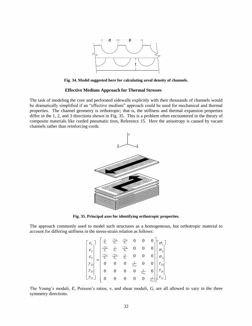
For the common case shown in Fig. 34 where the laminae are all the same thickness, a simple calculation
shows that
𝜌1 =𝑐ℎ𝑎𝑛𝑛𝑒𝑙 𝐴 𝑝𝑒𝑟𝑖𝑚𝑒𝑡𝑒𝑟
𝑐ℎ𝑎𝑛𝑛𝑒𝑙 𝐴 𝑝𝑖𝑡𝑐ℎ (1/t)
=(1+
𝜋
2)𝑑𝐴
𝑝𝐴 𝑡
𝜌2 =𝑐ℎ𝑎𝑛𝑛𝑒𝑙 𝐵 𝑝𝑒𝑟𝑖𝑚𝑒𝑡𝑒𝑟
𝑐ℎ𝑎𝑛𝑛𝑒𝑙 𝐵 𝑝𝑖𝑡𝑐ℎ (1/t)
=(1+
𝜋
2)𝑑𝐵
𝑝𝐵 𝑡 ,
and where t is the lamina thickness. Finally,
𝑇𝑎𝑣 =𝑇1+(𝜌2/𝜌1)𝑇2
2=
𝑇1+𝑑𝐵𝑑𝐴
𝑝𝐴 𝑝𝐵
𝑇2
2 ,
where
𝑇1 = 𝑇𝐴 −𝑄𝐴
ℎ𝐴
𝑇2 = 𝑇𝐵 +𝑄𝐵
ℎ𝐵
Q is the local heat flux and h is the heat transfer coefficient appropriate for the fluid velocity and position
along the channel. For the upset case where one side depressurizes, say side B, the heat flux vanishes and
Tav = TA, where TA is spatially, but not necessarily temporally invariant.
TA>TB }
32
Fig. 34. Model suggested here for calculating areal density of channels.
Effective Medium Approach for Thermal Stresses
The task of modeling the core and perforated sidewalls explicitly with their thousands of channels would
be dramatically simplified if an “effective medium” approach could be used for mechanical and thermal
properties. The channel geometry is orthotropic; that is, the stiffness and thermal expansion properties
differ in the 1, 2, and 3 directions shown in Fig. 35. This is a problem often encountered in the theory of
composite materials like corded pneumatic tires, Reference 15. Here the anisotropy is caused by vacant
channels rather than reinforcing cords.
Fig. 35. Principal axes for identifying orthotropic properties.
The approach commonly used to model such structures as a homogeneous, but orthotropic material to
account for differing stiffness in the stress-strain relation as follows:
3121
1 2 3
3212
1 2 3
13 23
1 2 3
23
31
12
1
1 11
2 2
1
3 3
123 23
131 31
112 12
0 0 0
0 0 0
0 0 0
0 0 0 0 0
0 0 0 0 0
0 0 0 0 0
E E E
E E E
E E E
G
G
G
The Young’s moduli, E, Poisson’s ratios, ν, and shear moduli, G, are all allowed to vary in the three
symmetry directions.

33
For thermal stress analysis, the expansion coefficients can also vary in the three principal directions.
Since thermal expansion generates no shear, the principal thermal expansion strains can be simply
incorporated into the strain vector. In this case we have (with α1 = α2 = α3 = α)
3121
1 2 3
3212
1 2 3
13 23
1 2 3
23
31
12
1
1 1 11
2 2 2
1
3 3 3
123 23
131 31
112 12
0 0 0
0 0 0
0 0 0
0 0 0 0 0
0 0 0 0 0
0 0 0 0 0
E E E
E E E
E E E
G
G
G
T
T
T
Manipulating the compliance matrices and their inverses (stiffness matrices) and incorporating these
orthotropic properties into a finite element method is discussed in the composite materials literature like
Reference 15.
It is anticipated that some of the anisotropic properties will be determined by physically applying forces
and shears to sections of actual cores. From an economic standpoint, finite element modeling of detailed
core sections rather than testing will be required for developing the anisotropic moduli and Poisson’s
ratios. Code tables or curves providing the anisotropic properties for various channel flow geometries
(counterflow, crossflow, etc.), channel pitch and diameter or lamina plate thicknesses will ultimately be
required for a simplified Code analysis.
While the macroscopic thermal stresses developed above can be directly applied to solid structures like
the solid portions of the sidewalls and the headers and header welds, stresses reported for the core and
perforated side plate effective media will not be directly suitable for Code analysis. This is because they
are based on a homogeneous model and do not reflect the channel-scale strain concentrations that will
develop if an array of channels is mathematically embedded in the macro stress or strain field.
Consequently, a model of the core that includes an array of channels (3x3, 5x5, or larger array) must be
embedded in the macroscopic strain field developed in the larger model, and the resulting strain or stress
concentrations should be evaluated for peak stresses, fatigue and creep strain limits at the channel-scale
level. An array of channels showing peak stress effects is discussed in Reference 16 and shown in Fig. 36
for pressure loading. Note that for cross flow conditions, the model will probably have to be three
dimensional and sections taken in the two flow directions. R&D work should be performed to develop
general rules for stress concentration factors for the channels to simplify the Code analysis.
Fig. 36. Channel array finite element model for calculating localized stresses in channel walls. After Ref 16.

34
5.2.2 Elastic-Perfectly Plastic Analysis Methodologies
As has been noted before, the complex passageways in a compact heat exchanger are a complicating
factor for performing the stress analysis required to assess elevated temperature cyclic life under
combined pressure and thermal gradient induced stresses. Other complicating factors are the sheer
number of structural features to be represented and stress concentrations at the corners of the flow
channels. Because of this complexity, it is difficult to apply the normal stress classification process of the
ASME Code. However, there are recently developed methodologies based on analysis approaches using
an elastic-perfectly plastic (EPP) model to limit various stress measures and strain accumulation.
The EPP methodologies provide conservative bounds to the evaluations of strain limits and creep-fatigue
damage under very high temperature conditions which cannot be adequately addressed by the current
Division 5 Code rules which are based on the distinction between rate independent plasticity and creep.
Such a distinction is invalid in materials operating at very high temperatures. The EPP methodologies
also have the advantage of not requiring the process of stress classification in the current Section III
Division 5 rules and they are also geared towards the modern finite element analysis tools.
Two ASME Section III, Division 5 Code Cases on strain limits and creep-fatigue evaluations using the
EPP methodologies have been developed and the ASME Code committee approval process is on-going.
5.2.3 Class B Design Rules
A review of the design requirements in ASME BPV, Section III, Division 5 requires that elevated
temperature Class B vessels designed by equation must satisfy the requirements of Division 1, NC-3300,
with some exceptions. This approach does not address thermal stresses or cyclic fatigue. The allowable
stresses are those listed in Division 5, Mandatory Appendix HCB-II, which are extensions of Tables 1A,
1B and 3 of Section II, Part D.
An examination of the design rules in NC-3300 shows that they are very similar to the rules in Section III,
Division 1. Thus there appear to be minimal differences between a Section III, Division 5, Class B design
and a Section VIII, Division 1 design. Allowable stresses are also similar between Section VIII and
Section III, Division 5, Class B where the temperatures overlap. In principle, few changes would be
required to Code Case 2621-1 covering diffusion bonded microchannel heat exchangers to make it
applicable to Section III, Division 5 Class B rules. Finally, if cyclic stresses are of concern for the design,
the use of Class B design rules is probably inappropriate. In that case, a Class A analysis and possibly
physical fatigue testing will be required to ensure an adequate design.
5.2.4 Code Boundaries
The assumption behind the Section III design methodology outlined above is that the diffusion bonded
sidewalls and endwalls are sufficiently robust to act as Class A pressure boundaries. In addition, since a
leak between Class A fluid channels and channels in Class B fluid service is a leak in a Class A pressure
boundary, core internal diffusion bonds must also be Class A quality. Thus, a heat exchanger containing
Class A system fluid is a Class A design and must meet Class A rules. It is probably incorrect to assume
that if a heat exchanger is placed in a containment vessel, the vessel can become the nuclear Code
boundary and design of the heat exchanger inside can be to ASME VIII rules. A Class A boundary still
exists inside the heat exchanger core. For the heat exchanger shown in Fig. 22, the only purely Class B
Code boundaries appear to be the Class B inlet and outlet headers.

35
6. INSPECTION AND TESTS
The non-destructive evaluation requirements for the construction of the diffusion bonded compact heat
exchangers are provided in Section VIII Code Case 2621-1. Helium leak testing side-to-side and both
sides to external is required. In addition, ultrasonic inspection of side/endwalls in the vicinity of header
attachment welds is required, along with the welds themselves. Liquid penetrant and visual examination
of all external surfaces (after machining) is required – no penetrant indications and unbound areas are
allowed. Finally, hydrostatic testing or pneumatic testing is required to Section VIII, Division 1, UG-99
or UG-100, respectively.
Bonding Procedure Specification and Bonding Performance Qualifications in Section IX of the Code
require the production of 8x8x8-inch bonded test blocks from which full-size tensile specimens are
extracted and tested. Three tensile tests in the through-bond and three in the lamina plane direction are
required. The minimum properties required in the original base metal specification must be met. In
addition, a microstructure sample must be removed from the test block and examined. The sample must
show complete fusion along the bond lines and be free of cracks in the bond or parent material.
An evaluation must be conducted to determine if these inspections and tests are sufficient for Section III
fabrication. Further, required in-service inspections have to be established. It is likely that more
ultrasonic inspection of sidewalls, endwalls and stack ends will be required for fabrication and in-service
inspections.
Volumetric inspection of core welds and perforated side plate/end plate welds will probably be impossible.
Consequently, weld strength reduction factors applicable to the creep rupture allowable, Sr, in Division 5,
Subsection HB, Subpart B should also be reviewed. Note that Section VIII, Division 1 welds that are not
volumetrically inspected require the use of a 0.7 joint efficiency factor on the allowable stress.
Finally, the need for 100- or 1000-hour creep tests and fatigue tests should be evaluated for bond
procedure qualification. We note that Heatric has done some work on creep and fatigue testing of
stainless steel printed diffusion bonded blocks, as reported in Reference 8. Kobe Steel has performed
fatigue tests on actual stainless steel cores, as reported in Reference 5. Fatigue testing on actual core
samples is probably the best approach for determining the fatigue behavior of microchannel designs.

36
7. FOULING
Little has been published on the fouling performance of microchannel heat exchangers. There is
obviously a concern since the channels are so small. The Heatric website discusses the need for in-line
filters and for providing header maintenance nozzles to accommodate pressure washing of the core. The
fouling potential for the coolants being considered for the high temperature reactor systems (sodium,
helium, sCO2) are almost completely unknown.
Fouling is a potentially critical issue for the economic feasibility of microchannel heat exchangers. A
review of current petrochemical experience with these heat exchangers should be conducted in the near
term to better evaluate this potential threat. Experience with cleaning should also be obtained.

37
8. CONCLUSIONS AND RECOMMENDATIONS
8.1 CONCLUSIONS
This report provides a brief review of the literature regarding compact heat exchangers along with a
summary of some ASME Code design considerations for the bonded microchannel designs. Based on
this review, we conclude the following:
1. The diffusion bond or DFW welding approach appears to produce sound welds with properties
similar to the base material.
2. The critical variables for producing diffusion bonds in the high chromium alloys of interest for high
temperature service are not public, and thus the sensitivity of the weld quality to these variables is
not generally known.
3. The load controlled stresses for the individual channels on the micro scale and the major
components of the heat exchanger (core, sidewalls, headers, etc.) on the macro scale are well
established based on existing Section VIII, Division 1 designs.
4. Methods for determining thermal stresses in the core and other major components must be
developed. One approach is suggested in this paper. There is no generally agreed upon approach
for calculating thermal stresses at this time, however.
5. Based on the fast thermal response of the diffusion bonded microchannel core, it is suspected that
thermal stresses, especially during transients, will be large.
6. The high thermal stresses combined with the thermal strain concentrations expected in the core
near the sidewalls, as well as at header attachment welds, will likely limit the design life to less
than 40 years.
7. The fact that most of the core diffusion bonds cannot be volumetrically inspected will be a problem
for acceptance of the design for ASME nuclear service. Current NDE requirements for Section
VIII heat exchangers will have to be augmented and in-service inspection requirements will have to
be developed essentially from scratch.
8. The potential for fouling of the microchannels is great and viable methods for cleaning a
contaminated, radioactive core have not been developed.
8.2 RECOMMENDATIONS
Based on our conclusions, we suggest the following research topics be considered to support the technical
development of the compact heat exchanger for nuclear service:
1. Welding development programs for diffusion bonding or DFW should be continued to establish
details of the currently accepted and possibly additional essential welding variables.
2. A Division 5, Class A stress analysis should be performed on a sample heat exchanger design.
Analysis methods for load controlled and strain controlled stresses should be developed and
applied. As a first cut, an evaluation using assumed isotropic core properties should be performed
to obtain early estimates of expected thermal stresses and possible design lifetimes.

38
3. The simplified analysis methods in Division 5, Appendix HBB-T employ the Bree approach which
considers the simultaneous application of primary and thermal loads for the purpose of evaluating
of elastic “shakedown” and ratcheting. This approach should be reviewed to determine if it is
applicable when macro thermal stresses caused by global constraint like that produced by the heat
exchanger walls and headers are imposed on an array of small channels like those in the PCHE
core. On the channel size scale, the imposed thermal stresses may look like primary stresses since
they may cause large local channel strains without self relief.
4. The development of an alternate Section III, Division 5 structural design methodology based on the
application of the EPP methodologies that provide for the assessment of the elevated temperature
failure modes of a compact heat exchanger under sustained and cyclic loading due to pressure and
thermal gradients should be pursued.
5. Research should be performed regarding the development of methods for determining the
orthotropic properties of a diffusion bonded core. Eventually, such properties should be
incorporated into the Code.
6. Rules for inspection and testing during fabrication and for in-service inspections should be
developed.
7. The potential for fouling of the microchannels should be explored based on the service experience
of current Section VIII vessels and on testing. Methods for cleaning should also be explored and
tested.

39
9. REFERENCES
1. Piyush Sabharwall, Denis E. Clark, Ronald E. Mizia, Michael V. Glazoff and Michael G.
McKellar, “Diffusion-Welded Microchannel Heat Exchanger for Industrial Processes, “ Journal of
Thermal Service and Engineering Applications, 5, (March 2013), 01109-1.
2. F. Jalilian, M. Jahazi and R. A. L. Drew, “Microstructure Evolution During Transient Liquid Phase
Bonding of Alloy 617,” Metallogr. Microstruct. Anal., 2 (2013), 170.
3. Hu Chen, Jianming Gong, Luyang Geng, and Shan-Tung Tu, “Finite Element Prediction of
Residual Stresses and Thermal Distortion in Brazed Plate-Fin Structure,” Journal of Pressure
Equipment and Systems, 3 (2005), 118.
4. Stephen John Dewson and Xiuqing Li, “Selection Criteria for the High Temperature Reactor
Intermediate Heat Exchanger,” Proceedings of ICAPP ’05, Paper 5333, May 15-19, 2005.
5. Yusutake Miwa, Dr. Koji Noishiki, Tomohiro Suzuki and Kenichi Takasuki, “Manufacturing
Technology of Diffusion-Bonded Compact Heat Exchanger (DHCE),” Kobelco Technology
Review, 32 (2013), 51.
6. Renaud Le Pierres, David Southall and Stephen Osborne, “Impact of Mechanical Design Issues on
Printed Circuit Heat Exchangers,” Proceedings of SCO2 Power Cycle Symposium 2011, May 24-
25, 2011.
7. David Southall and Stephen John Dewson, “Innovative Compact Heat Exchangers,” Proceedings of
ICAPP ’10, June 13-17, 2010, Paper 10300, American Nuclear Society.
8. David Southall, “Diffusion Bonding in Compact Heat Exchangers,” Proceedings of ICAPP ’09,
May 10-14, 2009, Paper 9069, American Nuclear Society.
9. David Southall, Renaud Le Pierres and Stephen John Dewson, “Design Considerations for
Compact Heat Exchangers,” Proceedings of ICAPP ’08, June 8-12, 2008, Paper 8009, American
Nuclear Society.
10. Xiuqing Li, Renaud le Pierres and Stephen John Dewson, “Heat Exchangers for the Next
Generation of Nuclear Reactors,” Proceedings of ICAP ’06, June 4-8, 2006, Paper 6105.
11. Sai K. Mylavarapu, Xiaodong Sun, Richard N. Christensen, Raymond R. Unocic, Richard E.
Glosup, and Mike V. Patterson, “Fabrication and Design Aspects of High-Temperature Compact
Diffusion Bonded Heat Exchangers,“ Nuclear Engineering and Design, 249 (2013), 49.
12. Xiuqing Li, David Kininmont, Renaud Le Pierres and Stephen John Dewson, “Alloy 617 for the
High Temperature Diffusion-Bonded Compact Heat Exchangers,” Proceedings of ICAPP ’08, June
8-12, 2008, Paper 8008.
13. V. Dostal, M. J. Driscoll and P. Hejzlar, “A Supercritical Carbon Dioxide Cycle for Next
Generation Nuclear Reactors,” MIT-ANP-TR-100, March 10, 2004.
14. Piyush Sabharwall, Eung Soo Kim, Ali Siahpush and Mike Patterson, “Preliminary Design for
Conventional and Compact Secondary Heat Exchanger in a Molten Salt Reactor,” INL/CON-12-
26385, July, 2012.

40
15. The Pneumatic Tire, DOT HS 810561, National Highway Traffic Safety Administration, February,
2006, Chapter 4.
16. T. M. Lillo, R. L. Williamson, T. R. Reed, C. B. Davis and D. M. Ginosar, “Engineering Analysis
of Intermediate Loop and Process Heat Exchanger Requirements to Include Configuration Analysis
and Materials Needs,” INL-EXT-05-00690, September, 2005.
17. J. Kesseli, J. Nash, A. Corbeil, Brayton Energy, LLC Presentation, “Plate Fin Heat Exchanger
Design for the Supercritical CO2 Cycle,” Symposium on Supercritical CO2 Power Cycle for Next
Generation Systems, March 6, 2007.
18. Scott R. Penfield, Jr., Phillip L. Rittenhouse, Renee Greyvenstein, James Nash, “IHX Design and
Development for the Next Generation Nuclear Plant,” Proceedings of the 4th International Topical
Meeting on High Temperature Reactor Technology, September 28-October 1, 2008

41
ORNL/TM-2015/401
Distribution List
Name Affiliation Email
Carlson, M. SNL [email protected]
Corwin, W. DOE [email protected]
Croson, D. INL [email protected]
Fleming, D. SNL [email protected]
Gougar, H. INL [email protected]
Grandy, C. ANL [email protected]
Hill, R.N. ANL [email protected]
Jetter, R.I. Consultant [email protected]
Majumdar, S. ANL [email protected]
Nestell, J. MPR [email protected]
Petti, D. INL [email protected]
Reeves, S. DOE [email protected]
Robinson, B. DOE [email protected]
Rochau, G. SNL [email protected]
Sham, T.-L. ORNL [email protected]
Sienicki, J. ANL [email protected]
Sink Jr, C.J. DOE [email protected]
Wang, J.-A. ORNL [email protected]
Wright, R.N. INL [email protected]