ASME B16.29
40
AN AMERICAN NATIONAL STANDARD ASME B16.29-2012 (Revision of ASME B16.29-2007) Wrought Copper and Wrought Copper Alloy Solder-Joint Drainage Fittings — DWV Copyright ASME International Provided by IHS under license with ASME Licensee=Repsol YPF/5982486001 Not for Resale, 04/04/2013 15:56:22 MDT No reproduction or networking permitted without license from IHS --``,,,,`,,`,`,``,,`,``,,```,,`,-`-`,,`,,`,`,,`---
description
B16.29
Transcript of ASME B16.29

A N A M E R I C A N N A T I O N A L S T A N D A R D
ASME B16.29-2012(Revision of ASME B16.29-2007)
Wrought Copper and Wrought Copper Alloy Solder-Joint Drainage Fittings — DWV
Copyright ASME International Provided by IHS under license with ASME Licensee=Repsol YPF/5982486001
Not for Resale, 04/04/2013 15:56:22 MDTNo reproduction or networking permitted without license from IHS
--``,,,,`,,`,`,``,,`,``,,```,,`,-`-`,,`,,`,`,,`---

Copyright ASME International Provided by IHS under license with ASME Licensee=Repsol YPF/5982486001
Not for Resale, 04/04/2013 15:56:22 MDTNo reproduction or networking permitted without license from IHS
--``,,,,`,,`,`,``,,`,``,,```,,`,-`-`,,`,,`,`,,`---

ASME B16.29-2012(Revision of ASME B16.29-2007)
Wrought Copper andWrought Copper AlloySolder-Joint DrainageFittings — DWV
A N A M E R I C A N N A T I O N A L S T A N D A R D
Three Park Avenue • New York, NY • 10016 USA
Copyright ASME International Provided by IHS under license with ASME Licensee=Repsol YPF/5982486001
Not for Resale, 04/04/2013 15:56:22 MDTNo reproduction or networking permitted without license from IHS
--``,,,,`,,`,`,``,,`,``,,```,,`,-`-`,,`,,`,`,,`---
Date of Issuance: September 26, 2012
The next edition of this Standard is scheduled for publication in 2017. There will be no addendaissued to this edition.
ASME issues written replies to inquiries concerning interpretations of technical aspects of thisStandard. Interpretations are published on the ASME Web site under the Committee Pages athttp://cstools.asme.org/ as they are issued.
Errata to codes and standards may be posted on the ASME Web site under the Committee Pages toprovide corrections to incorrectly published items, or to correct typographical or grammatical errorsin codes and standards. Such errata shall be used on the date posted.
The Committee Pages can be found at http://cstools.asme.org/. There is an option available toautomatically receive an e-mail notification when errata are posted to a particular code or standard.This option can be found on the appropriate Committee Page after selecting “Errata” in the “PublicationInformation” section.
ASME is the registered trademark of The American Society of Mechanical Engineers.
This code or standard was developed under procedures accredited as meeting the criteria for American NationalStandards. The Standards Committee that approved the code or standard was balanced to assure that individuals fromcompetent and concerned interests have had an opportunity to participate. The proposed code or standard was madeavailable for public review and comment that provides an opportunity for additional public input from industry, academia,regulatory agencies, and the public-at-large.ASME does not “approve,” “rate,” or “endorse” any item, construction, proprietary device, or activity.ASME does not take any position with respect to the validity of any patent rights asserted in connection with any
items mentioned in this document, and does not undertake to insure anyone utilizing a standard against liability forinfringement of any applicable letters patent, nor assume any such liability. Users of a code or standard are expresslyadvised that determination of the validity of any such patent rights, and the risk of infringement of such rights, isentirely their own responsibility.Participation by federal agency representative(s) or person(s) affiliated with industry is not to be interpreted as
government or industry endorsement of this code or standard.ASME accepts responsibility for only those interpretations of this document issued in accordance with the established
ASME procedures and policies, which precludes the issuance of interpretations by individuals.
No part of this document may be reproduced in any form,in an electronic retrieval system or otherwise,
without the prior written permission of the publisher.
The American Society of Mechanical EngineersThree Park Avenue
New York, NY 10016-5990
Copyright © 2012 byTHE AMERICAN SOCIETY OF MECHANICAL ENGINEERS
All rights reservedPrinted in U.S.A.
Copyright ASME International Provided by IHS under license with ASME Licensee=Repsol YPF/5982486001
Not for Resale, 04/04/2013 15:56:22 MDTNo reproduction or networking permitted without license from IHS
--``,,,,`,,`,`,``,,`,``,,```,,`,-`-`,,`,,`,`,,`---

CONTENTS
Foreword . . . . . . . . . . . . . . . . . . . . . . . . . . . . . . . . . . . . . . . . . . . . . . . . . . . . . . . . . . . . . . . . . . . . . . . . . . . . . . ivCommittee Roster . . . . . . . . . . . . . . . . . . . . . . . . . . . . . . . . . . . . . . . . . . . . . . . . . . . . . . . . . . . . . . . . . . . . . vCorrespondence With the B16 Committee . . . . . . . . . . . . . . . . . . . . . . . . . . . . . . . . . . . . . . . . . . . . . . viSummary of Changes . . . . . . . . . . . . . . . . . . . . . . . . . . . . . . . . . . . . . . . . . . . . . . . . . . . . . . . . . . . . . . . . . . vii
1 Scope . . . . . . . . . . . . . . . . . . . . . . . . . . . . . . . . . . . . . . . . . . . . . . . . . . . . . . . . . . . . . . . . . . . . . . . . . . . . . 1
2 General . . . . . . . . . . . . . . . . . . . . . . . . . . . . . . . . . . . . . . . . . . . . . . . . . . . . . . . . . . . . . . . . . . . . . . . . . . . 1
3 Description . . . . . . . . . . . . . . . . . . . . . . . . . . . . . . . . . . . . . . . . . . . . . . . . . . . . . . . . . . . . . . . . . . . . . . . . 1
4 Pitch (Slope) . . . . . . . . . . . . . . . . . . . . . . . . . . . . . . . . . . . . . . . . . . . . . . . . . . . . . . . . . . . . . . . . . . . . . . 1
5 Abbreviations . . . . . . . . . . . . . . . . . . . . . . . . . . . . . . . . . . . . . . . . . . . . . . . . . . . . . . . . . . . . . . . . . . . . . . 1
6 Component Size . . . . . . . . . . . . . . . . . . . . . . . . . . . . . . . . . . . . . . . . . . . . . . . . . . . . . . . . . . . . . . . . . . . 1
7 Marking . . . . . . . . . . . . . . . . . . . . . . . . . . . . . . . . . . . . . . . . . . . . . . . . . . . . . . . . . . . . . . . . . . . . . . . . . . . 2
8 Material . . . . . . . . . . . . . . . . . . . . . . . . . . . . . . . . . . . . . . . . . . . . . . . . . . . . . . . . . . . . . . . . . . . . . . . . . . . 2
9 Laying Lengths . . . . . . . . . . . . . . . . . . . . . . . . . . . . . . . . . . . . . . . . . . . . . . . . . . . . . . . . . . . . . . . . . . . . 2
10 Ovality . . . . . . . . . . . . . . . . . . . . . . . . . . . . . . . . . . . . . . . . . . . . . . . . . . . . . . . . . . . . . . . . . . . . . . . . . . . . 2
11 Threaded Ends. . . . . . . . . . . . . . . . . . . . . . . . . . . . . . . . . . . . . . . . . . . . . . . . . . . . . . . . . . . . . . . . . . . . . 2
12 Design of Threaded Ends . . . . . . . . . . . . . . . . . . . . . . . . . . . . . . . . . . . . . . . . . . . . . . . . . . . . . . . . . . . 2
13 Alignment . . . . . . . . . . . . . . . . . . . . . . . . . . . . . . . . . . . . . . . . . . . . . . . . . . . . . . . . . . . . . . . . . . . . . . . . . 2
14 Gaging . . . . . . . . . . . . . . . . . . . . . . . . . . . . . . . . . . . . . . . . . . . . . . . . . . . . . . . . . . . . . . . . . . . . . . . . . . . . 2
Figure1 Size of Fittings . . . . . . . . . . . . . . . . . . . . . . . . . . . . . . . . . . . . . . . . . . . . . . . . . . . . . . . . . . . . . . . . . . . 3
Tables1 Dimensions of Solder-Joint Ends . . . . . . . . . . . . . . . . . . . . . . . . . . . . . . . . . . . . . . . . . . . . . . . . . . 42 Dimensions of Threaded Ends — DWV . . . . . . . . . . . . . . . . . . . . . . . . . . . . . . . . . . . . . . . . . . . 53 Dimensions of DWV Couplings, Extended Bushings, and Adapters . . . . . . . . . . . . . . . . 64 Dimensions of DWV Soil Pipe Adapters . . . . . . . . . . . . . . . . . . . . . . . . . . . . . . . . . . . . . . . . . . . 75 Dimensions of DWV C � No-Hub Soil Pipe Adapters . . . . . . . . . . . . . . . . . . . . . . . . . . . . . 86 Dimensions of DWV Elbows . . . . . . . . . . . . . . . . . . . . . . . . . . . . . . . . . . . . . . . . . . . . . . . . . . . . . . 97 Dimensions of DWV 45 deg Y′s . . . . . . . . . . . . . . . . . . . . . . . . . . . . . . . . . . . . . . . . . . . . . . . . . . . 108 Dimensions of DWV Tees . . . . . . . . . . . . . . . . . . . . . . . . . . . . . . . . . . . . . . . . . . . . . . . . . . . . . . . . . 119 Dimensions of DWV Caps . . . . . . . . . . . . . . . . . . . . . . . . . . . . . . . . . . . . . . . . . . . . . . . . . . . . . . . . 1110 Dimensions of DWV Vent Increasers . . . . . . . . . . . . . . . . . . . . . . . . . . . . . . . . . . . . . . . . . . . . . . 1211 Dimensions of DWV Closet Flanges . . . . . . . . . . . . . . . . . . . . . . . . . . . . . . . . . . . . . . . . . . . . . . . 1312 Dimensions of DWV Trap Adapters . . . . . . . . . . . . . . . . . . . . . . . . . . . . . . . . . . . . . . . . . . . . . . . 1413 Dimensions of DWV Slip-Joint Ends . . . . . . . . . . . . . . . . . . . . . . . . . . . . . . . . . . . . . . . . . . . . . . 14
Mandatory AppendicesI U.S. Customary Dimensions . . . . . . . . . . . . . . . . . . . . . . . . . . . . . . . . . . . . . . . . . . . . . . . . . . . . . . 15II References . . . . . . . . . . . . . . . . . . . . . . . . . . . . . . . . . . . . . . . . . . . . . . . . . . . . . . . . . . . . . . . . . . . . . . . . 27
Nonmandatory AppendixA Quality System Program . . . . . . . . . . . . . . . . . . . . . . . . . . . . . . . . . . . . . . . . . . . . . . . . . . . . . . . . . . 28
iii
Copyright ASME International Provided by IHS under license with ASME Licensee=Repsol YPF/5982486001
Not for Resale, 04/04/2013 15:56:22 MDTNo reproduction or networking permitted without license from IHS
--``,,,,`,,`,`,``,,`,``,,```,,`,-`-`,,`,,`,`,,`---

FOREWORD
Standardization of cast and wrought solder-joint fittings was initiated in Subcommittee 11 ofAmerican Standards Association (ASA) Sectional Committee A40 on Plumbing Requirementsand Equipment. Development work culminated in publication of ASA A40.3-1941.
In 1949, work on these fittings was transferred to Sectional Committee B16 of ASA, whichestablished Subcommittee 9 (now Subcommittee J). The first standard developed was approvedas ASA B16.18-1950, Cast Bronze Solder-Joint Fittings. A later joint effort of the Copper and BrassResearch Association and the Manufacturers Standardization Society of the Valve and FittingsIndustry (MSS) culminated in a standard on wrought fittings, ultimately approved as B16.22-1951.
Concurrently, recognizing the need for drainage fitting standards, an MSS task group developedthe standard later approved as ASA B16.23-1953, Cast Bronze Solder-Joint Drainage Fittings, anda standard for wrought fittings was initially published as MSS SP-64-1961. A revision of thatstandard was submitted to Subcommittee 9 of B16 and was eventually approved asASA B16.29-1966.
A revision was published [after reorganization of ASA as the American National StandardsInstitute (ANSI)] as ANSI B16.29-1973. In this edition, shorter solder cups were specified in largersizes, since strength to contain pressure is not a factor. In 1979, Subcommittee I (formerly 9,now J) added metric dimensional equivalents and made other minor improvements. That revisionwas approved by ANSI, after approval by the Committee and secretariat organizations, asANSI B16.29-1980.
In 1982, American National Standards Committee B16 was reorganized as an ASME Committeeoperating under procedures accredited by ANSI. The 1986 Edition of the standard removedmetric equivalents (not functionally applicable in the plumbing industry), updated the referencedstandards, and incorporated editorial and format revisions. The 1994 Edition removed inspectiontolerance requirements, established minimum laying lengths, added soil pipe adapters, andincorporated editorial revisions. Following approval by the Standards Committee and ASME,approval as an American National Standard was given by ANSI on October 10, 1994, with thedesignator ASME B16.29-1994.
The 2001 Edition of this Standard was revised to include Nonmandatory Appendix B, QualitySystem Program. Editorial revisions were made for the purpose of clarification. Following approvalby the B16 Main Committee and ASME Supervisory Board, this Standard was approved as anAmerican National Standard by ANSI on October 11, 2001.
In the 2007 Edition, metric units were used as a primary reference unit while maintainingU.S. Customary units in either parenthetical or separate forms. In addition, several editorials andrevisions have been made for clarity.
In this 2012 Edition, references to ASME standards were revised to no longer list specific editionyears; the latest edition of ASME publications applies unless stated otherwise. Following approvalby the B16 Standards Committee and the ASME Supervisory Board, and after public review, thisStandard was approved as an American National Standard by ANSI on August 23, 2012.
Requests for interpretations or suggestions for revisions should be sent to the Secretary,B16 Committee, The American Society of Mechanical Engineers, Three Park Avenue, New York,NY 10016-5990.
iv
Copyright ASME International Provided by IHS under license with ASME Licensee=Repsol YPF/5982486001
Not for Resale, 04/04/2013 15:56:22 MDTNo reproduction or networking permitted without license from IHS
--``,,,,`,,`,`,``,,`,``,,```,,`,-`-`,,`,,`,`,,`---

ASME B16 COMMITTEEStandardization of Valves, Flanges, Fittings, and Gaskets
(The following is the roster of the Committee at the time of approval of this Standard.)
STANDARDS COMMITTEE OFFICERS
W. B. Bedesem, ChairG. A. Jolly, Vice ChairD. R. Sharp, Secretary
STANDARDS COMMITTEE PERSONNEL
A. Appleton, Alloy Stainless Products Co., Inc.R. W. Barnes, Anric Enterprises, Inc.W. B. Bedesem, ConsultantR. M. Bojarczuk, ExxonMobil Research & Engineering Co.D. F. Buccicone, ConsultantA. M. Cheta, Shell Exploration and Production Co.M. A. Clark, Nibco, Inc.G. A. Cuccio, Capitol Manufacturing Co.C. E. Davila, Crane EnergyD. R. Frikken, Becht Engineering Co.R. P. Griffiths, U.S. Coast Guard
SUBCOMMITTEE J — COPPER AND COPPER ALLOY FLANGES
M. A. Clark, Chair, Nibco, Inc.D. F. Buccicone, Vice Chair, ConsultantC. E. O’Brien, Secretary, The American Society of MechanicalEngineers
J. A. Ballanco, JB Engineering & Code ConsultingS. L. Cavanaugh, Cavanaugh ConsultingA. Ciechanowski, NSF InternationalD. R. Frikken, Becht Engineering Co.
v
G. A. Jolly, Vogt Valves/Flowserve Corp.M. Katcher, Haynes InternationalW. N. McLean, B&L EngineeringT. A. McMahon, Emerson Process ManagementM. L. Nayyar, Bechtel Power Corp.W. H. Patrick, The Dow Chemical Co.R. A. Schmidt, CanadoilD. R. Sharp, The American Society of Mechanical EngineersH. R. Sonderegger, Fluoroseal, Inc.W. M. Stephan, Flexitallic LPF. R. Volgstadt, Volgstadt & Associates, Inc.D. A. Williams, Southern Co. Generation
M. Gillespie, Viega North AmericaT. L. Jamison, Jamison EngineeringA. G. Kireta, Jr., Copper Development Association, Inc.A. A. Knapp, A. Knapp & AssociatesC. A. Stout, Mueller Industries, Inc.R. M. McKenzie, Alternate, Mueller Fittings Co., Inc.C. Mueller, Alternate, Mueller Industries, Inc.
Copyright ASME International Provided by IHS under license with ASME Licensee=Repsol YPF/5982486001
Not for Resale, 04/04/2013 15:56:22 MDTNo reproduction or networking permitted without license from IHS
--``,,,,`,,`,`,``,,`,``,,```,,`,-`-`,,`,,`,`,,`---
CORRESPONDENCE WITH THE B16 COMMITTEE
General. ASME Standards are developed and maintained with the intent to represent theconsensus of concerned interests. As such, users of this Standard may interact with the Committeeby requesting interpretations, proposing revisions, and attending Committee meetings. Corre-spondence should be addressed to:
Secretary, B16 Standards CommitteeThe American Society of Mechanical EngineersThree Park AvenueNew York, NY 10016-5990
As an alternative, inquiries may be submitted via e-mail to: [email protected] Revisions. Revisions are made periodically to the standard to incorporate changes
that appear necessary or desirable, as demonstrated by the experience gained from the applicationof the standard. Approved revisions will be published periodically.
The Committee welcomes proposals for revisions to this Standard. Such proposals should beas specific as possible, citing the paragraph number(s), the proposed wording, and a detaileddescription of the reasons for the proposal, including any pertinent documentation.
Interpretations. Upon request, the B16 Committee will render an interpretation of any require-ment of the standard. Interpretations can only be rendered in response to a written request sentto the Secretary of the B16 Standards Committee.
The request for interpretation should be clear and unambiguous. It is further recommendedthat the inquirer submit his/her request in the following format:
Subject: Cite the applicable paragraph number(s) and the topic of the inquiry.Edition: Cite the applicable edition of the Standard for which the interpretation is
being requested.Question: Phrase the question as a request for an interpretation of a specific requirement
suitable for general understanding and use, not as a request for an approvalof a proprietary design or situation. The inquirer may also include any plansor drawings that are necessary to explain the question; however, they shouldnot contain proprietary names or information.
Requests that are not in this format will be rewritten in this format by the Committee priorto being answered, which may inadvertently change the intent of the original request.
ASME procedures provide for reconsideration of any interpretation when or if additionalinformation that might affect an interpretation is available. Further, persons aggrieved by aninterpretation may appeal to the cognizant ASME Committee or Subcommittee. ASME does not“approve,” “certify,” “rate,” or “endorse” any item, construction, proprietary device, or activity.
Attending Committee Meetings. The B16 Standards Committee regularly holds meetings, whichare open to the public. Persons wishing to attend any meeting should contact the Secretary ofthe B16 Standards Committee.
vi
Copyright ASME International Provided by IHS under license with ASME Licensee=Repsol YPF/5982486001
Not for Resale, 04/04/2013 15:56:22 MDTNo reproduction or networking permitted without license from IHS
--``,,,,`,,`,`,``,,`,``,,```,,`,-`-`,,`,,`,`,,`---

ASME B16.29-2012SUMMARY OF CHANGES
Following approval by the ASME B16 Committee and ASME, and after public review,ASME B16.29-2012 was approved by the American National Standards Institute onAugust 23, 2012.
ASME B16.29-2012 includes the following changes identified by a margin note, (12). In addition,in the main text, the “General” section was moved to section 2, and subsequent sections andtheir paragraphs were renumbered accordingly. All paragraph references were then revised asneeded. Throughout the text, the words “male” and “female” were changed to “external” and“internal,” respectively.
Page Location Change
1 5 Revised
2 11.1 Revised
11.3 (1) Revised(2) Split into paras. 11.3.1 and 11.3.2
27 Mandatory Appendix II Updated
28 Nonmandatory RevisedAppendix A
vii
Copyright ASME International Provided by IHS under license with ASME Licensee=Repsol YPF/5982486001
Not for Resale, 04/04/2013 15:56:22 MDTNo reproduction or networking permitted without license from IHS
--``,,,,`,,`,`,``,,`,``,,```,,`,-`-`,,`,,`,`,,`---
INTENTIONALLY LEFT BLANK
viii
Copyright ASME International Provided by IHS under license with ASME Licensee=Repsol YPF/5982486001
Not for Resale, 04/04/2013 15:56:22 MDTNo reproduction or networking permitted without license from IHS
--``,,,,`,,`,`,``,,`,``,,```,,`,-`-`,,`,,`,`,,`---

ASME B16.29-2012
WROUGHT COPPER AND WROUGHT COPPER ALLOYSOLDER-JOINT DRAINAGE FITTINGS — DWV
1 SCOPE
This Standard for wrought copper and wrought cop-per alloy solder-joint drainage fittings, designed for usewith copper drainage tube conforming to ASTM B306,covers the following:
(a) description(b) pitch (slope)(c) abbreviations for end connections(d) sizes and method of designating openings for
reducing fittings(e) marking(f) material(g) dimensions and tolerances
2 GENERAL
2.1 Convention
For determining conformance with this Standard, theconvention for fixing significant digits where limits(maximum and minimum values) are specified shall beas defined in ASTM E29. This requires that an observedor calculated value be rounded off to the nearest unitin the last right-hand digit used for expressing the limit.Decimal values and tolerances do not imply a particularmethod of measurement.
2.2 Relevant Units
This Standard states values in both SI (metric) andU.S. Customary units. These systems of units are to beregarded separately as standard. Within the text, theU.S. Customary units are shown in parentheses or inseparate tables that appear in Mandatory Appendix I.The values stated in each system are not exact equiva-lents; therefore, it is required that each system of unitsbe used independently of the other. Combining valuesfrom the two systems constitutes nonconformance withthe Standard.
2.3 References
Codes, standards, and specifications, containing pro-visions to the extent referenced herein, constituterequirements of this Standard. These reference docu-ments are listed in Mandatory Appendix II.
1
2.4 Quality Systems
Guidelines relating to the product manufacturer’squality system programs are described inNonmandatory Appendix A.
3 DESCRIPTION
These fittings are designed for drainage and vent sys-tems only, using the solder-joint method of connection.The fitting cups (C) are provided with stops so thatthe ends of the tube, when assembled, meet the stops.Sketches and designs of fittings are illustrative only. Thedimensions specified herein shall govern in all cases.
4 PITCH (SLOPE)
All nominal 90-deg fittings shall be pitched to resultin a slope of 0.20 mm/m (0.25 in./ft) (2%) of horizontaltube length with reference to a horizontal plane.
5 ABBREVIATIONS
The symbols shown below are used to designate thetype of fitting end.
Symbols Definitions
C Solder-joint fitting end (internal) made toreceive copper tube diameter
F Internal American National Standard taper pipethread, NPTI
FTG Solder-joint fitting end (external) made to cop-per tube diameter
M External American National Standard taper pipethread, NPTE
NPSM American National Standard free-fitting straightmechanical pipe thread
SJ End of fitting formed to receive outside diame-ter tube size
6 COMPONENT SIZE
6.1 Nominal Size
As applied in this Standard, the use of the phrase“nominal size” followed by a dimensionless number isfor the purpose of fitting end connection sizeidentification.
(12)
Copyright ASME International Provided by IHS under license with ASME Licensee=Repsol YPF/5982486001
Not for Resale, 04/04/2013 15:56:22 MDTNo reproduction or networking permitted without license from IHS
--``,,,,`,,`,`,``,,`,``,,```,,`,-`-`,,`,,`,`,,`---
(12)
ASME B16.29-2012
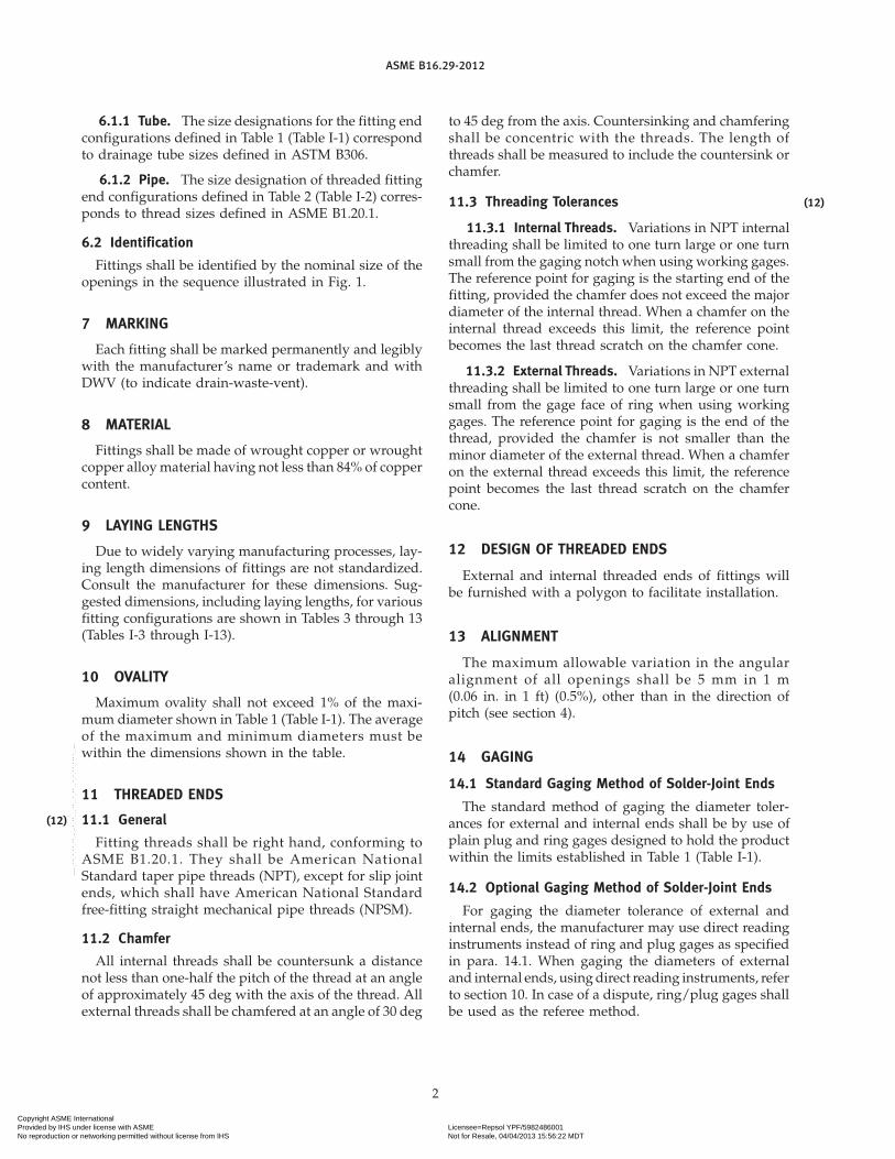
6.1.1 Tube. The size designations for the fitting endconfigurations defined in Table 1 (Table I-1) correspondto drainage tube sizes defined in ASTM B306.
6.1.2 Pipe. The size designation of threaded fittingend configurations defined in Table 2 (Table I-2) corres-ponds to thread sizes defined in ASME B1.20.1.
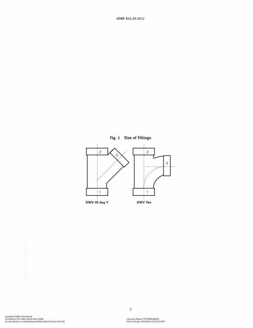
6.2 Identification
Fittings shall be identified by the nominal size of theopenings in the sequence illustrated in Fig. 1.
7 MARKING
Each fitting shall be marked permanently and legiblywith the manufacturer’s name or trademark and withDWV (to indicate drain-waste-vent).
8 MATERIAL
Fittings shall be made of wrought copper or wroughtcopper alloy material having not less than 84% of coppercontent.
9 LAYING LENGTHS
Due to widely varying manufacturing processes, lay-ing length dimensions of fittings are not standardized.Consult the manufacturer for these dimensions. Sug-gested dimensions, including laying lengths, for variousfitting configurations are shown in Tables 3 through 13(Tables I-3 through I-13).
10 OVALITY
Maximum ovality shall not exceed 1% of the maxi-mum diameter shown in Table 1 (Table I-1). The averageof the maximum and minimum diameters must bewithin the dimensions shown in the table.
11 THREADED ENDS
11.1 General
Fitting threads shall be right hand, conforming toASME B1.20.1. They shall be American NationalStandard taper pipe threads (NPT), except for slip jointends, which shall have American National Standardfree-fitting straight mechanical pipe threads (NPSM).
11.2 Chamfer
All internal threads shall be countersunk a distancenot less than one-half the pitch of the thread at an angleof approximately 45 deg with the axis of the thread. Allexternal threads shall be chamfered at an angle of 30 deg
2
to 45 deg from the axis. Countersinking and chamferingshall be concentric with the threads. The length ofthreads shall be measured to include the countersink orchamfer.
11.3 Threading Tolerances
11.3.1 Internal Threads. Variations in NPT internalthreading shall be limited to one turn large or one turnsmall from the gaging notch when using working gages.The reference point for gaging is the starting end of thefitting, provided the chamfer does not exceed the majordiameter of the internal thread. When a chamfer on theinternal thread exceeds this limit, the reference pointbecomes the last thread scratch on the chamfer cone.
11.3.2 External Threads. Variations in NPT externalthreading shall be limited to one turn large or one turnsmall from the gage face of ring when using workinggages. The reference point for gaging is the end of thethread, provided the chamfer is not smaller than theminor diameter of the external thread. When a chamferon the external thread exceeds this limit, the referencepoint becomes the last thread scratch on the chamfercone.
12 DESIGN OF THREADED ENDS
External and internal threaded ends of fittings willbe furnished with a polygon to facilitate installation.
13 ALIGNMENT
The maximum allowable variation in the angularalignment of all openings shall be 5 mm in 1 m(0.06 in. in 1 ft) (0.5%), other than in the direction ofpitch (see section 4).
14 GAGING
14.1 Standard Gaging Method of Solder-Joint Ends
The standard method of gaging the diameter toler-ances for external and internal ends shall be by use ofplain plug and ring gages designed to hold the productwithin the limits established in Table 1 (Table I-1).
14.2 Optional Gaging Method of Solder-Joint Ends
For gaging the diameter tolerance of external andinternal ends, the manufacturer may use direct readinginstruments instead of ring and plug gages as specifiedin para. 14.1. When gaging the diameters of externaland internal ends, using direct reading instruments, referto section 10. In case of a dispute, ring/plug gages shallbe used as the referee method.
(12)
Copyright ASME International Provided by IHS under license with ASME Licensee=Repsol YPF/5982486001
Not for Resale, 04/04/2013 15:56:22 MDTNo reproduction or networking permitted without license from IHS
--``,,,,`,,`,`,``,,`,``,,```,,`,-`-`,,`,,`,`,,`---
ASME B16.29-2012
Fig. 1 Size of Fittings
1 1
3
3
DWV 45 deg Y DWV Tee
2 2
3
Copyright ASME International Provided by IHS under license with ASME Licensee=Repsol YPF/5982486001
Not for Resale, 04/04/2013 15:56:22 MDTNo reproduction or networking permitted without license from IHS
--``,,,,`,,`,`,``,,`,``,,```,,`,-`-`,,`,,`,`,,`---

ASME B16.29-2012
Table 1 Dimensions of Solder-Joint Ends
R
G
GRK
A
O
O
A F
F
R
External End
(FTG)
Internal End
(FTG)
R
External End Internal End MinimumMinimum InsideOutside Diameter, Inside Diameter, F
Nominal Minimum Minimum Metal Diameter ofA [Note (2)] [Note (2)]Tube Size Length, K Depth, G Thickness, R Fitting, O[Note (1)] Min. Max. [Note (3)] Min. Max. [Note (3)] [Note (4)] [Note (5)]
11⁄4 34.85 34.98 14.22 35.00 35.10 12.70 1.02 32.7711⁄2 41.17 41.33 15.75 41.35 41.48 14.22 1.07 38.862 53.87 54.03 17.53 54.05 54.18 15.75 1.07 51.053 79.27 79.43 20.57 79.45 79.58 19.05 1.14 75.694 104.67 104.83 26.92 104.85 104.98 25.40 1.47 99.82
GENERAL NOTE: Dimensions are in millimeters.
NOTES:(1) For size designation of fitting, see section 6.(2) See section 10.(3) K dimensions of 11.2 mm, 12.7 mm, and 14.2 mm and G dimensions of 9.7 mm, 11.2 mm, and 12.7 mm, respectively, for sizes 11⁄4,
11⁄2, and 2 are sound and acceptable from an engineering standpoint. However, the cup depths specified provide greater latitude inmaking accurate installations.
(4) R dimension is based on DWV tubing, which is intended for above-ground use.(5) Inside diameter of fitting is based on Type M copper water tube (ASTM B88).
4
Copyright ASME International Provided by IHS under license with ASME Licensee=Repsol YPF/5982486001
Not for Resale, 04/04/2013 15:56:22 MDTNo reproduction or networking permitted without license from IHS
--``,,,,`,,`,`,``,,`,``,,```,,`,-`-`,,`,,`,`,,`---

ASME B16.29-2012
Table 2 Dimensions of Threaded Ends — DWV
S
30 deg, min.B
Z
ZZ
AC O
O
Y
M
P
Internal Threaded End
(F)
External Threaded End
(M)
Note (1)
Internal End [Note (2)] External End [Note (3)]
Minimum MinimumDia. of Dia. of Minimum Minimum Maximum Minimum
Nominal Band or Minimum Body Inside Minimum Minimum Inside Thread Length ofThread Across Band Over Dia. of Length of Depth of Dia. of End EffectiveSize Flats of Length, Thread, Fitting, Thread, Bore, Fitting, Bore, Thread,
[Note (4)] Polygon, A B C O M, Min. Y S, Min. Z O P ZZ
11⁄4 45.2 8.6 43.7 32.8 42.2 10.7 18.3 17.5 32.8 34.8 18.011⁄2 52.3 9.7 50.3 38.9 48.3 10.7 18.3 17.5 38.9 40.9 18.32 64.3 12.7 63.0 51.1 60.5 11.2 20.6 19.1 51.1 52.6 19.33 94.5 14.2 93.5 75.7 88.9 19.6 32.5 31.0 75.7 78.2 30.5
GENERAL NOTE: Dimensions are in millimeters.
NOTES:(1) 11⁄4, 1
1⁄2, and 2 male threaded ends may have inside chamfer for slip–nut connections.(2) Internal threads shall be gaged from 1⁄2 turn large to 1
1⁄2 turn small from the gaging notch on the plug when using working gages.(3) External threads shall be gaged 1⁄2 turn small to 1
1⁄2 turn large from the face of the ring when using working gages.(4) Thread size is as governed by ASME B1.20.1.
5
Copyright ASME International Provided by IHS under license with ASME Licensee=Repsol YPF/5982486001
Not for Resale, 04/04/2013 15:56:22 MDTNo reproduction or networking permitted without license from IHS
--``,,,,`,,`,`,``,,`,``,,```,,`,-`-`,,`,,`,`,,`---

ASME B16.29-2012
Table 3 Dimensions of DWV Couplings, Extended Bushings, and Adapters
C CB
C X F C X M
DWV Couplings
Without Stop
C X C
With Stop
C X C
Reducing
C X C
DWV Adapters
FTG X M
B
Extended Bushing
FTG X C
C
FTG X F
B
A A
Minimum Minimum MinimumAdaptersMinimum Coupling Couplings Bushing
Nominal Couplings Reducer Without Extended Minimum Minimum Minimum MinimumThread or C � C, C � C, Stop C � C, FTG � C, C � F, C � M, FTG � F, FTG � M,Tube Size A A C B B B C C
11⁄4 1.5 . . . 25.4 . . . 18.5 21.8 34.5 . . .11⁄4 � 11⁄2 . . . . . . . . . . . . . . . 31.2 . . . . . .11⁄2 1.5 . . . 28.4 . . . 18.5 21.8 37.6 42.911⁄2 � 11⁄4 . . . 4.8 . . . 20.6 . . . 24.9 . . . . . .11⁄2 � 2 . . . . . . . . . . . . . . . 37.6 . . . . . .
2 1.5 . . . 31.8 . . . 21.8 21.8 40.9 . . .2 � 11⁄2 . . . 6.4 . . . 26.9 . . . . . . . . . . . .2 � 11⁄4 . . . 6.4 . . . 25.4 . . . 23.4 . . . . . .3 1.5 . . . 38.1 . . . 33.8 36.8 55.9 . . .3 � 2 . . . 6.4 . . . 28.4 . . . . . . . . . . . .
3 � 11⁄2 . . . 7.9 . . . 28.4 . . . . . . . . . . . .3 � 11⁄4 . . . 7.9 . . . 30.2 . . . . . . . . . . . .4 1.5 . . . 50.8 . . . . . . . . . . . . . . .4 � 3 . . . 9.7 . . . 36.6 . . . . . . . . . . . .
GENERAL NOTE: Dimensions are in millimeters.
6
Copyright ASME International Provided by IHS under license with ASME Licensee=Repsol YPF/5982486001
Not for Resale, 04/04/2013 15:56:22 MDTNo reproduction or networking permitted without license from IHS
--``,,,,`,,`,`,``,,`,``,,```,,`,-`-`,,`,,`,`,,`---

ASME B16.29-2012
Table 4 Dimensions of DWV Soil Pipe Adapters
J
H
J
H
N
TT
N AA
Straight Size
C X Spigot
DWV Soil Pipe Adapters
Reducing Size
C X Spigot
Nominal Size
Dimension 2 � 2 11⁄2 � 2 11⁄4 � 2 3 � 3 2 � 3 4 � 4 3 � 4
A, max. 69.9 69.9 69.9 98.6 98.6 124.0 124.0A, min. 68.3 68.3 68.3 96.8 96.8 122.2 122.2H, min. 60 81 81 6 86 73 92J, min. 64 87 87 73 95 83 103N 62.2 62.2 62.2 88.6 88.6 114.0 114.0T, min. 1.37 1.37 1.37 1.60 1.60 1.83 1.83
GENERAL NOTES:(a) Dimensions are in millimeters.(b) Dimensions are for extra-heavyweight soil pipe (reference ASTM A74). For service weight soil pipe, A and N nominal dimensions may
be from 3 mm to 8 mm smaller than dimensions shown in table.
7
Copyright ASME International Provided by IHS under license with ASME Licensee=Repsol YPF/5982486001
Not for Resale, 04/04/2013 15:56:22 MDTNo reproduction or networking permitted without license from IHS
--``,,,,`,,`,`,``,,`,``,,```,,`,-`-`,,`,,`,`,,`---

ASME B16.29-2012
Table 5 Dimensions of DWV C � No-Hub SoilPipe Adapters
A A B B
D D
F F
Reducing Size
DWV Soil Pipe Adapters – C X No-Hub
for Use With Stainless Steel Clamp and Elastomer Gasket
Straight Size
NominalF+3.3−0.00Size A ± 1.5 B ± 1.5 D, Min.
2 60.5 58.7 31.0 6.411⁄2 � 2 60.5 58.7 31.8 6.411⁄4 � 2 60.5 58.7 32.5 6.43 86.6 84.8 31.0 6.4
2 � 3 86.6 84.8 31.8 6.411⁄2 � 3 86.6 84.8 32.5 6.44 112.8 111.3 31.0 7.93 � 4 112.8 111.3 31.8 7.9
GENERAL NOTE: Dimensions are in millimeters.
8
Copyright ASME International Provided by IHS under license with ASME Licensee=Repsol YPF/5982486001
Not for Resale, 04/04/2013 15:56:22 MDTNo reproduction or networking permitted without license from IHS
--``,,,,`,,`,`,``,,`,``,,```,,`,-`-`,,`,,`,`,,`---

ASME B16.29-2012
Table 6 Dimensions of DWV Elbows
K
KK
K
DWV 90 deg Ell
C X C
DWV 221/2 deg Ell
C X C
Pitch
K
DWV 60 deg Ell
C X C
K
G
K
DWV 45 deg Ell
C X CDWV 90 deg FTG Ell
FTC X C
Pit
ch
K
G
K
K
DWV 111/4 deg Ell
C X C
DWV Elbows
DWV 45 deg FTG Ell
FTG X C
K
K
Nominal Tube Size
Angle Dimensions 11⁄4, Min. 11⁄2, Min. 2, Min. 3, Min. 4, Min.
90 deg C � C K 28.2 34.5 47.2 70.4 93.7
60 deg C � C K 15.5 18.5 26.4 40.1 . . .
45 deg C � C K 10.7 12.2 18.5 27.4 36.6
221⁄2 deg C � C K 2.8 4.3 7.6 11.4 15.7
111⁄4 deg C � C K 1.0 1.0 2.8 3.6 7.9
90 deg FTG � C K 28.2 33.0 47.2 70.4 93.7G 42.4 50.3 64.5 90.9 120.9
45 deg FTG � C K 10.7 12.2 18.5 27.4 36.6G 24.9 28.2 36.1 48.0 63.5
GENERAL NOTE: Dimensions are in millimeters.
9
Copyright ASME International Provided by IHS under license with ASME Licensee=Repsol YPF/5982486001
Not for Resale, 04/04/2013 15:56:22 MDTNo reproduction or networking permitted without license from IHS
--``,,,,`,,`,`,``,,`,``,,```,,`,-`-`,,`,,`,`,,`---
ASME B16.29-2012
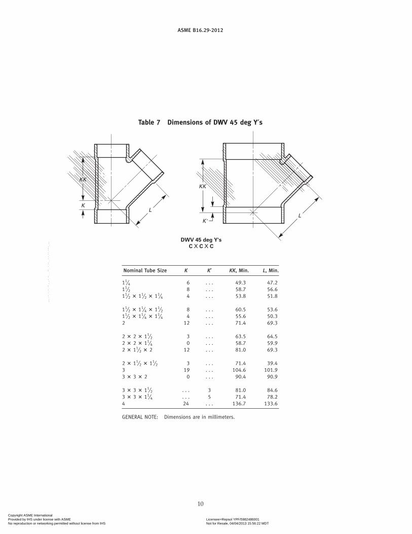
Table 7 Dimensions of DWV 45 deg Y′s
KK
KL
DWV 45 deg Y's
C X C X C
KK
K'L
Nominal Tube Size K K′ KK, Min. L, Min.
11⁄4 6 . . . 49.3 47.211⁄2 8 . . . 58.7 56.611⁄2 � 11⁄2 � 11⁄4 4 . . . 53.8 51.8
11⁄2 � 11⁄4 � 11⁄2 8 . . . 60.5 53.611⁄2 � 11⁄4 � 11⁄4 4 . . . 55.6 50.32 12 . . . 71.4 69.3
2 � 2 � 11⁄2 3 . . . 63.5 64.52 � 2 � 11⁄4 0 . . . 58.7 59.92 � 11⁄2 � 2 12 . . . 81.0 69.3
2 � 11⁄2 � 11⁄2 3 . . . 71.4 39.43 19 . . . 104.6 101.93 � 3 � 2 0 . . . 90.4 90.9
3 � 3 � 11⁄2 . . . 3 81.0 84.63 � 3 � 11⁄4 . . . 5 71.4 78.24 24 . . . 136.7 133.6
GENERAL NOTE: Dimensions are in millimeters.
10
Copyright ASME International Provided by IHS under license with ASME Licensee=Repsol YPF/5982486001
Not for Resale, 04/04/2013 15:56:22 MDTNo reproduction or networking permitted without license from IHS
--``,,,,`,,`,`,``,,`,``,,```,,`,-`-`,,`,,`,`,,`---

ASME B16.29-2012
Table 8 Dimensions of DWV Tees
J
K
KK
DWV Tees
C X C X C
Pitch
Nominal Tube Size J, Min. K, Min. KK, Min.
11⁄4 26.7 26.4 19.111⁄2 33.0 33.0 20.611⁄2 � 11⁄2 � 11⁄4 29.7 26.4 20.6
11⁄2 � 11⁄4 � 11⁄2 34.5 34.5 23.911⁄2 � 11⁄4 � 11⁄4 31.2 28.2 23.92 42.4 45.7 26.9
2 � 2 � 11⁄2 37.6 31.2 22.42 � 2 � 11⁄4 36.1 26.4 19.12 � 11⁄2 � 2 42.9 45.7 33.3
2 � 11⁄2 � 11⁄2 37.6 33.0 30.23 63.8 70.4 42.93 � 3 � 2 54.4 45.0 28.7
3 � 3 � 11⁄2 49.5 32.3 23.93 � 3 � 11⁄4 48.0 25.7 20.64 95.5 95.5 52.3
GENERAL NOTE: Dimensions are in millimeters.
11
Table 9 Dimensions of DWV Caps
A
DWV Caps
C
Nominal Tube Size A
11⁄4 1811⁄2 192 21
GENERAL NOTE: Dimensions are in millimeters.
Copyright ASME International Provided by IHS under license with ASME Licensee=Repsol YPF/5982486001
Not for Resale, 04/04/2013 15:56:22 MDTNo reproduction or networking permitted without license from IHS
--``,,,,`,,`,`,``,,`,``,,```,,`,-`-`,,`,,`,`,,`---
ASME B16.29-2012
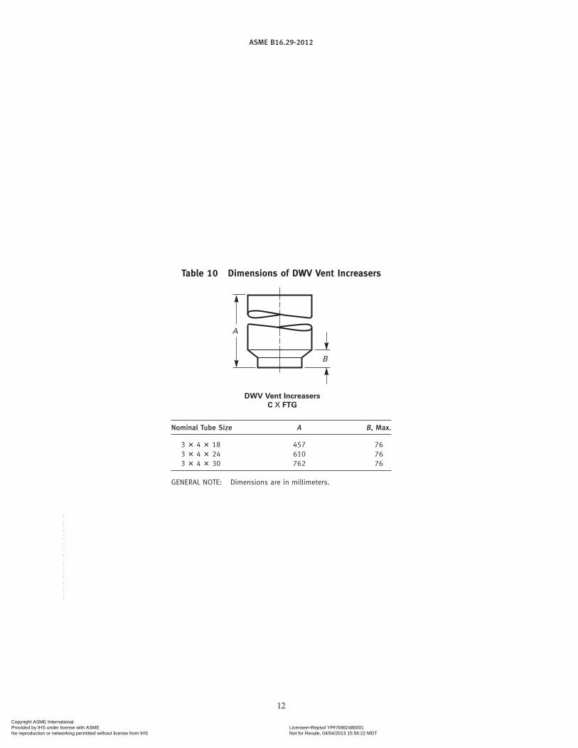
Table 10 Dimensions of DWV Vent Increasers
A
B
DWV Vent Increasers
C X FTG
Nominal Tube Size A B, Max.
3 � 4 � 18 457 763 � 4 � 24 610 763 � 4 � 30 762 76
GENERAL NOTE: Dimensions are in millimeters.
12
Copyright ASME International Provided by IHS under license with ASME Licensee=Repsol YPF/5982486001
Not for Resale, 04/04/2013 15:56:22 MDTNo reproduction or networking permitted without license from IHS
--``,,,,`,,`,`,``,,`,``,,```,,`,-`-`,,`,,`,`,,`---

ASME B16.29-2012
Table 11 Dimensions of DWV Closet Flanges
D
DD
Quarter Slot With Holes
Suggested Slot Arrangements
Half Slot
Size 3 Closet FlangeSize 4 Closet Flange
W W
UUUU
EE
V
1.5 min.
1.5 min.
30 deg30 deg17 deg
15.79.5
45 deg [Note (2)]
12.7
12.71.5
Note (1)
D
DD
DD
221/2 deg 221/2 deg
45 deg
12.7
7.6 diameter hole with 12.7 diameter C' sink
7.9
DD
Nominal V, Min.Size D, Min. DD EE UU, Min. [Note (3)] W
3 171.5 152 105 39.6 74.7 6.44 171.5 152 . . . 15.7 . . . 6.4
GENERAL NOTE: Dimensions are in millimeters.
NOTES:(1) Tube stop optional.(2) 45-deg angle may be extended to face of flange.(3) For flange with tube stop.
13
Copyright ASME International Provided by IHS under license with ASME Licensee=Repsol YPF/5982486001
Not for Resale, 04/04/2013 15:56:22 MDTNo reproduction or networking permitted without license from IHS
--``,,,,`,,`,`,``,,`,``,,```,,`,-`-`,,`,,`,`,,`---

ASME B16.29-2012
Table 12 Dimensions of DWV Trap Adapters
A A
C X SJFTG X SJ
Nominal Size FTG � SJ, A C � SJ, A
11⁄4 27.7 12.711⁄2 29.5 12.711⁄2 � 11⁄4 30.2 15.7
GENERAL NOTE: Dimensions are in millimeters.
Table 13 Dimensions of DWV Slip-Joint Ends
A
C
B
13.5 min.
11.1 min.
DA
Gasket [Note (2)] Nut [Note (3)]
Fitting
SJ
Note (1)7.9 min.
Gasket Nut
Nominal NominalDiameter Inside Minimum Nut Hole
Nominal of Thread, Diameter of Length of Diameter,Size A Gasket, B Gasket, C D
11⁄4 11⁄4 NPSM 32.0 4.1 32.511⁄2 11⁄2 NPSM 38.4 4.8 38.9
GENERAL NOTE: Dimensions are in millimeters.
NOTES:(1) Angles must be equal.(2) Gasket to be pliable, not subject to aging or drying out.(3) Nut may be any material specified in section 8 or other suit-
able nonferrous alloy.
14
Copyright ASME International Provided by IHS under license with ASME Licensee=Repsol YPF/5982486001
Not for Resale, 04/04/2013 15:56:22 MDTNo reproduction or networking permitted without license from IHS
--``,,,,`,,`,`,``,,`,``,,```,,`,-`-`,,`,,`,`,,`---

ASME B16.29-2012
MANDATORY APPENDIX IU.S. CUSTOMARY DIMENSIONS
This Mandatory Appendix provides tables of the stan-dard inch dimensions for fittings (Tables I-1 throughI-13).
15
Copyright ASME International Provided by IHS under license with ASME Licensee=Repsol YPF/5982486001
Not for Resale, 04/04/2013 15:56:22 MDTNo reproduction or networking permitted without license from IHS
--``,,,,`,,`,`,``,,`,``,,```,,`,-`-`,,`,,`,`,,`---

ASME B16.29-2012
Table I-1 Dimensions of Solder-Joint Ends
R
G
GRK
A
O
O
A F
F
R
External End
(FTG)
Internal End
(FTG)
R
External End Internal End MinimumNominal Minimum InsideOutside Diameter, Inside Diameter, FTube Minimum Minimum Metal Diameter ofA [Note (2)] [Note (2)]Size Length, K Depth, G Thickness, R Fitting, O
[Note (1)] Min. Max. [Note (3)] Min. Max. [Note (3)] [Note (4)] [Note (5)]
11⁄4 1.372 1.377 0.56 1.378 1.382 0.50 0.040 1.2911⁄2 1.621 1.627 0.62 1.628 1.633 0.56 0.042 1.532 2.121 2.127 0.69 2.128 2.133 0.62 0.042 2.013 3.121 3.127 0.81 3.128 3.133 0.75 0.045 2.984 4.121 4.127 1.06 4.128 4.133 1.00 0.058 3.93
GENERAL NOTE: Dimensions are in inches.
NOTES:(1) For size designation of fitting, see section 6.(2) See section 10.(3) K dimensions of 0.44 in., 0.50 in., and 0.56 in. and G dimensions of 0.38 in., 0.44 in., and 0.50 in., respectively, for sizes 11⁄4, 1
1⁄2,and 2 are sound and acceptable from an engineering standpoint. However, the cup depths specified provide greater latitude in makingaccurate installations.
(4) R dimension is based on DWV tubing, which is intended for above-ground use.(5) Inside diameter of fitting is based on Type M copper water tube (ASTM B88).
16
Copyright ASME International Provided by IHS under license with ASME Licensee=Repsol YPF/5982486001
Not for Resale, 04/04/2013 15:56:22 MDTNo reproduction or networking permitted without license from IHS
--``,,,,`,,`,`,``,,`,``,,```,,`,-`-`,,`,,`,`,,`---
ASME B16.29-2012
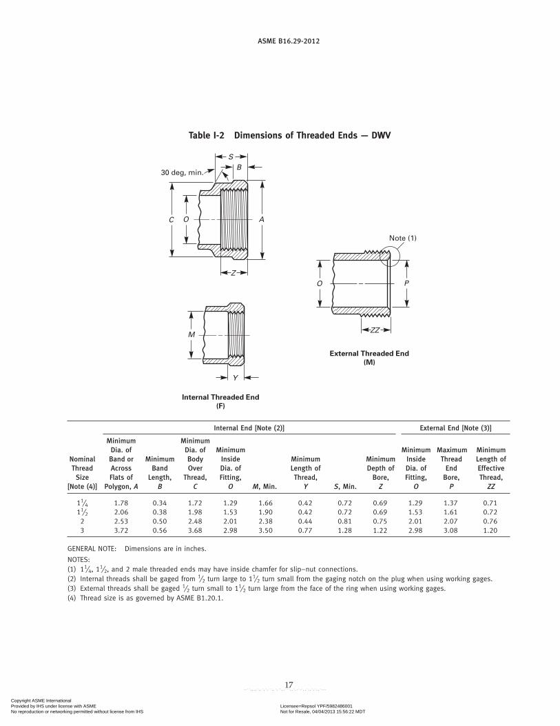
Table I-2 Dimensions of Threaded Ends — DWV
S
30 deg, min.B
Z
ZZ
AC O
O
Y
M
P
Internal Threaded End
(F)
External Threaded End
(M)
Note (1)
Internal End [Note (2)] External End [Note (3)]
Minimum MinimumDia. of Dia. of Minimum Minimum Maximum Minimum
Nominal Band or Minimum Body Inside Minimum Minimum Inside Thread Length ofThread Across Band Over Dia. of Length of Depth of Dia. of End EffectiveSize Flats of Length, Thread, Fitting, Thread, Bore, Fitting, Bore, Thread,
[Note (4)] Polygon, A B C O M, Min. Y S, Min. Z O P ZZ
11⁄4 1.78 0.34 1.72 1.29 1.66 0.42 0.72 0.69 1.29 1.37 0.7111⁄2 2.06 0.38 1.98 1.53 1.90 0.42 0.72 0.69 1.53 1.61 0.722 2.53 0.50 2.48 2.01 2.38 0.44 0.81 0.75 2.01 2.07 0.763 3.72 0.56 3.68 2.98 3.50 0.77 1.28 1.22 2.98 3.08 1.20
GENERAL NOTE: Dimensions are in inches.
NOTES:(1) 11⁄4, 1
1⁄2, and 2 male threaded ends may have inside chamfer for slip–nut connections.(2) Internal threads shall be gaged from 1⁄2 turn large to 1
1⁄2 turn small from the gaging notch on the plug when using working gages.(3) External threads shall be gaged 1⁄2 turn small to 1
1⁄2 turn large from the face of the ring when using working gages.(4) Thread size is as governed by ASME B1.20.1.
17
Copyright ASME International Provided by IHS under license with ASME Licensee=Repsol YPF/5982486001
Not for Resale, 04/04/2013 15:56:22 MDTNo reproduction or networking permitted without license from IHS
--``,,,,`,,`,`,``,,`,``,,```,,`,-`-`,,`,,`,`,,`---

ASME B16.29-2012
Table I-3 Dimensions of DWV Couplings, Extended Bushings, and Adapters
C CB
C X F C X M
DWV Couplings
Without Stop
C X C
With Stop
C X C
Reducing
C X C
DWV Adapters
FTG X M
B
Extended Bushing
FTG X C
C
FTG X F
B
A A
Minimum Minimum MinimumAdaptersMinimum Coupling Couplings Bushing
Nominal Couplings Reducer Without Extended Minimum Minimum Minimum MinimumThread or C � C, C � C, Stop C � C, FTG � C, C � F, C � M, FTG � F, FTG � M,Tube Size A A C B B B C C
11⁄4 0.06 . . . 1.00 . . . 0.73 0.86 1.36 . . .11⁄4 � 11⁄2 . . . . . . . . . . . . . . . 1.23 . . . . . .11⁄2 0.06 . . . 1.12 . . . 0.73 0.86 1.48 1.6911⁄2 � 11⁄4 . . . 0.19 . . . 0.81 . . . 0.98 . . . . . .11⁄2 � 2 . . . . . . . . . . . . . . . 1.48 . . . . . .
2 0.06 . . . 1.25 . . . 0.86 0.86 1.61 . . .2 � 11⁄2 . . . 0.25 . . . 1.06 . . . . . . . . . . . .2 � 11⁄4 . . . 0.25 . . . 1.00 . . . 0.92 . . . . . .3 0.06 . . . 1.50 . . . 1.33 1.45 2.20 . . .3 � 2 . . . 0.25 . . . 1.12 . . . . . . . . . . . .
3 � 11⁄2 . . . 0.31 . . . 1.12 . . . . . . . . . . . .3 � 11⁄4 . . . 0.31 . . . 1.19 . . . . . . . . . . . .4 0.06 . . . 2.00 . . . . . . . . . . . . . . .4 � 3 . . . 0.38 . . . 1.44 . . . . . . . . . . . .
GENERAL NOTE: Dimensions are in inches.
18
Copyright ASME International Provided by IHS under license with ASME Licensee=Repsol YPF/5982486001
Not for Resale, 04/04/2013 15:56:22 MDTNo reproduction or networking permitted without license from IHS
--``,,,,`,,`,`,``,,`,``,,```,,`,-`-`,,`,,`,`,,`---
ASME B16.29-2012
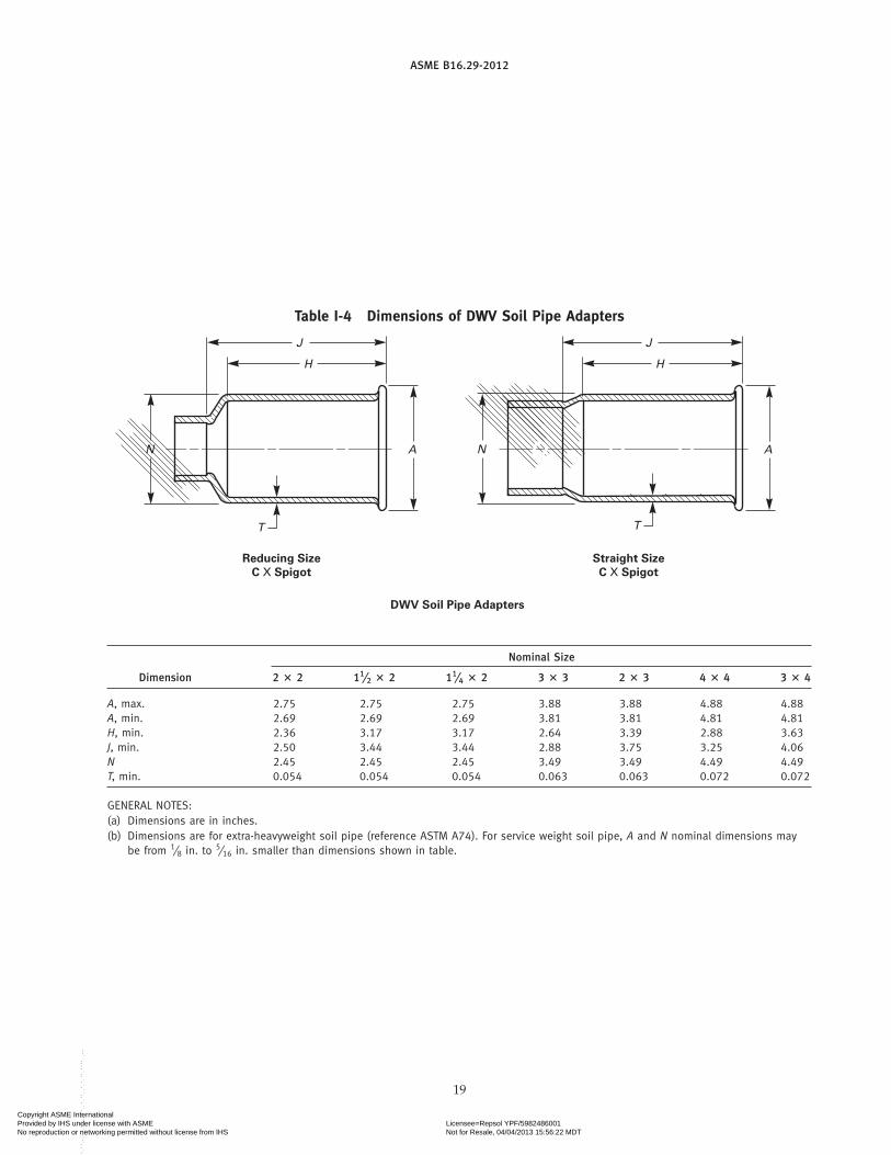
Table I-4 Dimensions of DWV Soil Pipe Adapters
J
H
J
H
N
TT
N AA
Straight Size
C X Spigot
DWV Soil Pipe Adapters
Reducing Size
C X Spigot
Nominal Size
Dimension 2 � 2 11⁄2 � 2 11⁄4 � 2 3 � 3 2 � 3 4 � 4 3 � 4
A, max. 2.75 2.75 2.75 3.88 3.88 4.88 4.88A, min. 2.69 2.69 2.69 3.81 3.81 4.81 4.81H, min. 2.36 3.17 3.17 2.64 3.39 2.88 3.63J, min. 2.50 3.44 3.44 2.88 3.75 3.25 4.06N 2.45 2.45 2.45 3.49 3.49 4.49 4.49T, min. 0.054 0.054 0.054 0.063 0.063 0.072 0.072
GENERAL NOTES:(a) Dimensions are in inches.(b) Dimensions are for extra-heavyweight soil pipe (reference ASTM A74). For service weight soil pipe, A and N nominal dimensions may
be from 1⁄8 in. to5⁄16 in. smaller than dimensions shown in table.
19
Copyright ASME International Provided by IHS under license with ASME Licensee=Repsol YPF/5982486001
Not for Resale, 04/04/2013 15:56:22 MDTNo reproduction or networking permitted without license from IHS
--``,,,,`,,`,`,``,,`,``,,```,,`,-`-`,,`,,`,`,,`---

ASME B16.29-2012
Table I-5 Dimensions of DWV C � No-Hub SoilPipe Adapters
A A B B
D D
F F
Reducing Size
DWV Soil Pipe Adapters – C X No-Hub
for Use With Stainless Steel Clamp and Elastomer Gasket
Straight Size
NominalF+0.13−0.00Size A ± 0.06 B ± 0.06 D, Min.
2 2.38 2.31 1.22 0.2511⁄2 � 2 2.38 2.31 1.25 0.2511⁄4 � 2 2.38 2.31 1.28 0.253 3.41 3.34 1.22 0.25
2 � 3 3.41 3.34 1.25 0.2511⁄2 � 3 3.41 3.34 1.28 0.254 4.44 4.38 1.22 0.313 � 4 4.44 4.38 1.25 0.31
GENERAL NOTE: Dimensions are in inches.
20
Copyright ASME International Provided by IHS under license with ASME Licensee=Repsol YPF/5982486001
Not for Resale, 04/04/2013 15:56:22 MDTNo reproduction or networking permitted without license from IHS
--``,,,,`,,`,`,``,,`,``,,```,,`,-`-`,,`,,`,`,,`---
ASME B16.29-2012
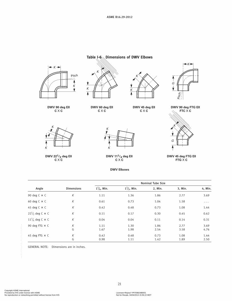
Table I-6 Dimensions of DWV Elbows
K
KK
K
DWV 90 deg Ell
C X C
DWV 221/2 deg Ell
C X C
Pitch
K
DWV 60 deg Ell
C X C
K
G
K
DWV 45 deg Ell
C X CDWV 90 deg FTG Ell
FTC X C
Pit
ch
K
G
K
K
DWV 111/4 deg Ell
C X C
DWV Elbows
DWV 45 deg FTG Ell
FTG X C
K
K
Nominal Tube Size
Angle Dimensions 11⁄4, Min. 11⁄2, Min. 2, Min. 3, Min. 4, Min.
90 deg C � C K 1.11 1.36 1.86 2.77 3.69
60 deg C � C K 0.61 0.73 1.04 1.58 . . .
45 deg C � C K 0.42 0.48 0.73 1.08 1.44
221⁄2 deg C � C K 0.11 0.17 0.30 0.45 0.62
111⁄4 deg C � C K 0.04 0.04 0.11 0.14 0.31
90 deg FTG � C K 1.11 1.30 1.86 2.77 3.69G 1.67 1.98 2.54 3.58 4.76
45 deg FTG � C K 0.42 0.48 0.73 1.08 1.44G 0.98 1.11 1.42 1.89 2.50
GENERAL NOTE: Dimensions are in inches.
21
Copyright ASME International Provided by IHS under license with ASME Licensee=Repsol YPF/5982486001
Not for Resale, 04/04/2013 15:56:22 MDTNo reproduction or networking permitted without license from IHS
--``,,,,`,,`,`,``,,`,``,,```,,`,-`-`,,`,,`,`,,`---
ASME B16.29-2012
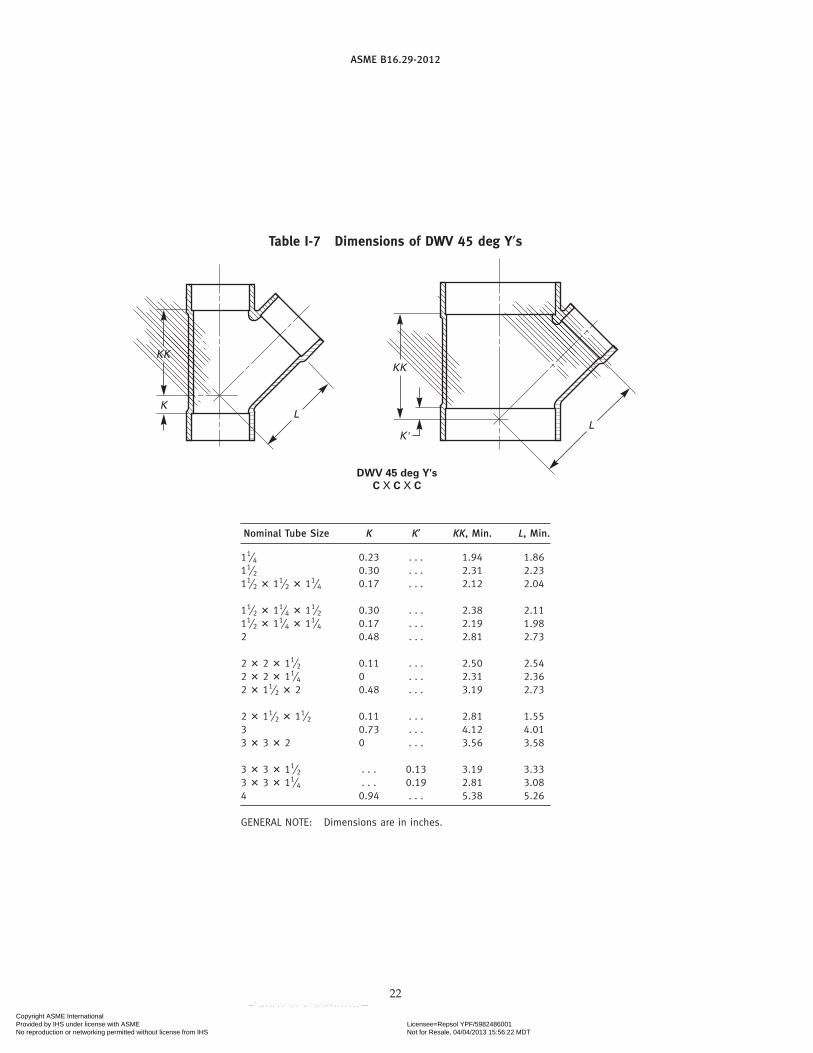
Table I-7 Dimensions of DWV 45 deg Y′s
KK
KL
DWV 45 deg Y's
C X C X C
KK
K'L
Nominal Tube Size K K′ KK, Min. L, Min.
11⁄4 0.23 . . . 1.94 1.8611⁄2 0.30 . . . 2.31 2.2311⁄2 � 11⁄2 � 11⁄4 0.17 . . . 2.12 2.04
11⁄2 � 11⁄4 � 11⁄2 0.30 . . . 2.38 2.1111⁄2 � 11⁄4 � 11⁄4 0.17 . . . 2.19 1.982 0.48 . . . 2.81 2.73
2 � 2 � 11⁄2 0.11 . . . 2.50 2.542 � 2 � 11⁄4 0 . . . 2.31 2.362 � 11⁄2 � 2 0.48 . . . 3.19 2.73
2 � 11⁄2 � 11⁄2 0.11 . . . 2.81 1.553 0.73 . . . 4.12 4.013 � 3 � 2 0 . . . 3.56 3.58
3 � 3 � 11⁄2 . . . 0.13 3.19 3.333 � 3 � 11⁄4 . . . 0.19 2.81 3.084 0.94 . . . 5.38 5.26
GENERAL NOTE: Dimensions are in inches.
22
Copyright ASME International Provided by IHS under license with ASME Licensee=Repsol YPF/5982486001
Not for Resale, 04/04/2013 15:56:22 MDTNo reproduction or networking permitted without license from IHS
--``,,,,`,,`,`,``,,`,``,,```,,`,-`-`,,`,,`,`,,`---

ASME B16.29-2012
Table I-8 Dimensions of DWV Tees
J
K
KK
DWV Tees
C X C X C
Pitch
Nominal Tube Size J, Min. K, Min. KK, Min.
11⁄4 1.05 1.04 0.7511⁄2 1.30 1.30 0.8111⁄2 � 11⁄2 � 11⁄4 1.17 1.04 0.81
11⁄2 � 11⁄4 � 11⁄2 1.36 1.36 0.9411⁄2 � 11⁄4 � 11⁄4 1.23 1.11 0.942 1.67 1.80 1.06
2 � 2 � 11⁄2 1.48 1.23 0.882 � 2 � 11⁄4 1.42 1.04 0.752 � 11⁄2 � 2 1.69 1.80 1.31
2 � 11⁄2 � 11⁄2 1.48 1.30 1.193 2.51 2.77 1.693 � 3 � 2 2.14 1.77 1.13
3 � 3 � 11⁄2 1.95 1.27 0.943 � 3 � 11⁄4 1.89 1.01 0.814 3.76 3.76 2.06
GENERAL NOTE: Dimensions are in inches.
23
Table I-9 Dimensions of DWV Caps
A
DWV Caps
C
Nominal Tube Size A
11⁄4 0.6911⁄2 0.752 0.81
GENERAL NOTE: Dimensions are in inches.
Copyright ASME International Provided by IHS under license with ASME Licensee=Repsol YPF/5982486001
Not for Resale, 04/04/2013 15:56:22 MDTNo reproduction or networking permitted without license from IHS
--``,,,,`,,`,`,``,,`,``,,```,,`,-`-`,,`,,`,`,,`---

ASME B16.29-2012
Table I-10 Dimensions of DWV Vent Increasers
A
B
DWV Vent Increasers
C X FTG
Nominal Tube Size A B, Max.
3 � 4 � 18 18 33 � 4 � 24 24 33 � 3 � 30 30 3
GENERAL NOTE: Dimensions are in inches.
24
Copyright ASME International Provided by IHS under license with ASME Licensee=Repsol YPF/5982486001
Not for Resale, 04/04/2013 15:56:22 MDTNo reproduction or networking permitted without license from IHS
--``,,,,`,,`,`,``,,`,``,,```,,`,-`-`,,`,,`,`,,`---

ASME B16.29-2012
Table I-11 Dimensions of DWV Closet Flanges
D
DD
Quarter Slot With Holes
Suggested Slot Arrangements
Half Slot
Size 3 Closet FlangeSize 4 Closet Flange
W W
UUUU
EE
V
0.06 min.
0.06 min.
30 deg30 deg17 deg
0.620.38
45 deg [Note (2)]
0.50
0.500.06
Note (1)
D
DD
DD
221/2 deg 221/2 deg
45 deg
0.50
0.30 diameter hole with 0.50 diameter C' sink
0.31
DD
Nominal V, Min.Size D, Min. DD EE UU, Min. [Note (3)] W
3 6.75 6.0 4.12 1.56 2.94 0.254 6.75 6.0 . . . 0.62 . . . 0.25
GENERAL NOTE: Dimensions are in inches.
NOTES:(1) Tube stop optional.(2) 45-deg angle may be extended to face of flange.(3) For flange with tube stop.
25
Copyright ASME International Provided by IHS under license with ASME Licensee=Repsol YPF/5982486001
Not for Resale, 04/04/2013 15:56:22 MDTNo reproduction or networking permitted without license from IHS
--``,,,,`,,`,`,``,,`,``,,```,,`,-`-`,,`,,`,`,,`---

ASME B16.29-2012
Table I-12 Dimensions of DWV Trap Adapters
A A
C X SJFTG X SJ
Nominal Size FTG � SJ, A C � SJ, A
11⁄4 1.09 0.5011⁄2 1.16 0.5011⁄2 � 11⁄4 1.19 0.62
GENERAL NOTE: Dimensions are in inches.
Table I-13 Dimensions of DWV Slip-Joint Ends
A
C
B
0.53 min.
0.44 min.
D A
Gasket [Note (2)]
Nut [Note (3)]
Fitting
SJ
Note (1)0.31 min.
Gasket Nut
Nominal NominalDiameter Inside Minimum Nut Hole
Nominal of Thread, Diameter of Length of Diameter,Size A Gasket, B Gasket, C D
11⁄4 11⁄4 NPSM 1.26 0.16 1.2811⁄2 11⁄2 NPSM 1.51 0.19 1.53
GENERAL NOTE: Dimensions are in inches.
NOTES:(1) Angles must be equal.(2) Gasket to be pliable, not subject to aging or drying out.(3) Nut may be any material specified in section 8 or other suit-
able nonferrous alloy.
26
Copyright ASME International Provided by IHS under license with ASME Licensee=Repsol YPF/5982486001
Not for Resale, 04/04/2013 15:56:22 MDTNo reproduction or networking permitted without license from IHS
--``,,,,`,,`,`,``,,`,``,,```,,`,-`-`,,`,,`,`,,`---

ASME B16.29-2012
MANDATORY APPENDIX IIREFERENCES
The following is a list of publications referenced inthis Standard. Unless otherwise specified, the latest edi-tion of ASME publications shall apply. Materials manu-factured to other editions of the referenced ASTMstandards may be used to manufacture fittings meetingthe requirements of this Standard as long as the fittingmanufacturer verifies that material meets the require-ments of the referenced edition.
ASME B1.20.1, Pipe Threads, General Purpose (Inch)ASME B16.22, Wrought Copper and Copper Alloy
Solder-Joint Pressure FittingsASME B16.23, Cast Copper Alloy Solder-Joint Drainage
Fittings (DWV)Publisher: The American Society of Mechanical
Engineers (ASME), Three Park Avenue, New York,NY 10016-5990; Order Department: 22 Law Drive, P.O.Box 2900, Fairfield, NJ 07007-2900 (www.asme.org)
ASTM A74-09, Standard Specification for Cast Iron SoilPipe and Fittings
ASTM B88-09, Standard Specification for SeamlessCopper Water Tube
27
ASTM B306-09, Standard Specification for CopperDrainage Tube (DWV)
ASTM E29-08, Standard Practice for Using SignificantDigits in Test Data to Determine Conformance WithSpecifications
Publisher: American Society for Testing and Materials(ASTM International), 100 Barr Harbor Drive, P.O.Box C700, West Conshohocken, PA 19428-2959(www.astm.org)
ISO 9000: 2005, Quality management systems —Fundamentals and vocabulary1
ISO 9001: 2008/Cor 1:2009, Quality managementsystems — Requirements1
ISO 9004: 2009, Managing for the sustained success ofan organization — A quality management approach1
Publisher: International Organization forStandardization (ISO) Central Secretariat, 1, ch. de laVoie-Creuse, Case postale 56, CH-1211, Geneve 20,Switzerland/Suisse (www.iso.org)
1 May also be obtained from American National StandardsInstitute (ANSI), 25 West 43rd Street, New York, NY 10036.
(12)
Copyright ASME International Provided by IHS under license with ASME Licensee=Repsol YPF/5982486001
Not for Resale, 04/04/2013 15:56:22 MDTNo reproduction or networking permitted without license from IHS
--``,,,,`,,`,`,``,,`,``,,```,,`,-`-`,,`,,`,`,,`---

(12)
ASME B16.29-2012
NONMANDATORY APPENDIX AQUALITY SYSTEM PROGRAM
The products manufactured in accordance with thisStandard shall be produced under a quality system pro-gram following the principles of an appropriate stan-dard from the ISO 9000 series.1 A determination of theneed for registration and/or certification of the product
1 The series is also available from the American NationalStandards Institute (ANSI) and the American Society for Quality(ASQ) as American National Standards that are identified by theprefix “Q,” replacing the prefix “ISO.” Each standard of the seriesis listed under References in Mandatory Appendix II.
28
manufacturer’s quality system program by an indepen-dent organization shall be the responsibility of the man-ufacturer. Detailed documentation demonstratingprogram compliance shall be available to the purchaserat the manufacturer ’s facility. A written, summarydescription of the program used by the product manu-facturer shall be available to the purchaser upon request.The product manufacturer is defined as the entity whosename or trademark appears on the product in accor-dance with the marking or identification requirementsof this Standard.
Copyright ASME International Provided by IHS under license with ASME Licensee=Repsol YPF/5982486001
Not for Resale, 04/04/2013 15:56:22 MDTNo reproduction or networking permitted without license from IHS
--``,,,,`,,`,`,``,,`,``,,```,,`,-`-`,,`,,`,`,,`---

Copyright ASME International Provided by IHS under license with ASME Licensee=Repsol YPF/5982486001
Not for Resale, 04/04/2013 15:56:22 MDTNo reproduction or networking permitted without license from IHS
--``,,,,`,,`,`,``,,`,``,,```,,`,-`-`,,`,,`,`,,`---

ASME B16.29-2012
N05712Copyright ASME International Provided by IHS under license with ASME Licensee=Repsol YPF/5982486001
Not for Resale, 04/04/2013 15:56:22 MDTNo reproduction or networking permitted without license from IHS
--``,,,,`,,`,`,``,,`,``,,```,,`,-`-`,,`,,`,`,,`---