ASHRAE WILL GIVE YOU THE WORLDashrae4greenville.com/resources/Newsletter/2014/Intro-to-Ammoni...Oil...
51
ASHRAE WILL GIVE YOU THE WORLD This ASHRAE Distinguished Lecturer is brought to you by the Society Chapter Technology Transfer Committee
Transcript of ASHRAE WILL GIVE YOU THE WORLDashrae4greenville.com/resources/Newsletter/2014/Intro-to-Ammoni...Oil...

ASHRAE WILL GIVE
YOU THE WORLD
This ASHRAE Distinguished Lecturer is brought to you by the Society Chapter Technology Transfer Committee

Complete the Distinguished Lecturer
Event Summary Critique
CTTC needs your feedback to continue to improve the DL Program Distribute the DL Evaluation Form to all attendees
Collect at the end of the meeting
Compile the attendee rating on the Event Summary Critique
Send the completed Event Summary Critique to your CTTC RVC and ASHRAE Headquarters
Forms are available at:
www.ashrae.org/distinguishedlecturers

BECOME A FUTURE LEADER IN ASHRAE – WRITE THE NEXT CHAPTER IN YOUR CAREER
YOU ARE NEEDED FOR:
Membership Promotion
Research Promotion
Student Activities
Chapter Technology
Transfer Technical
Committees
Find your Place in ASHRAE! Visit www.ashrae.org
ASHRAE Members who attend their monthly chapter meetings become
leaders and bring information and technology back to their job.

Douglas Reindl, Ph.D., P.E.
ASHRAE Fellow
Director, IRC
Professor, University of Wisconsin-Madison
An Introduction to Ammonia Refrigeration Systems

5
During this presentation, we will discuss
• Brief background on ammonia and its uses
• Ammonia, the refrigerant
• Ammonia refrigeration, the technology
• How is ammonia different compared to other refrigerants?

6
Where is ammonia used?
87%
11%
2%**
Annual ammonia use in U.S.
Agriculture Other Refrigerant
Annual US consumption in 2012 was 14.4 million metric tons*.
• Source: US Geological Survey (2013).
** Source: ASHRAE Position Document on ammonia (RA 2013)
NH3

9
Anhydrous ammonia as a refrigerant
•Where is ammonia used as a refrigerant?
– Industrial systems: large cold storage and process systems
– Some HVAC systems (requires a central plant)
– Where no ODP and low/no GWP is desirable/needed
• Distinct characteristics
– Usually a custom engineered system vs. a packaged systems for halocarbons
10
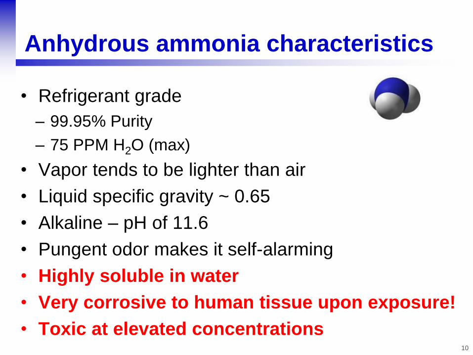
Anhydrous ammonia characteristics
• Refrigerant grade
– 99.95% Purity
– 75 PPM H2O (max)
• Vapor tends to be lighter than air
• Liquid specific gravity ~ 0.65
• Alkaline – pH of 11.6
• Pungent odor makes it self-alarming
• Highly soluble in water
• Very corrosive to human tissue upon exposure!
• Toxic at elevated concentrations

11
Flammability characteristics
• ASHRAE 34 flammability classification: 2L
• DOT classified as non-flammable
• Autoignition temperature: 1204F
• Lower flammability limit (vol.%)1 15-16
• Upper flammability limit (vol. %)1 25-28
• Combustion products: oxides of nitrogen
• Fire hazard: slight
1 IIAR Ammonia Data Book, (2009).

12

13
14
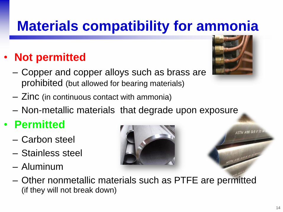
Materials compatibility for ammonia
• Not permitted
– Copper and copper alloys such as brass are prohibited (but allowed for bearing materials)
– Zinc (in continuous contact with ammonia)
– Non-metallic materials that degrade upon exposure
• Permitted
– Carbon steel
– Stainless steel
– Aluminum
– Other nonmetallic materials such as PTFE are permitted (if they will not break down)

15
• Why is ammonia widely used in food processing
and storage facilities?
• Because it is a good refrigerant!
– High heat transfer coefficients in equipment
– Efficient compressor operation
– Low refrigerant cost
– No ozone depletion & very low/no global warming
– Sustainable
– Self-alarming
Anhydrous ammonia

Let’s now look at the technology

17
Ammonia refrigeration technology
• Single stage compression with evaporators configured as
– direct-expansion
– flooded
– overfeed
• Multi-stage compression systems
• Cascade systems

18
Simple vapor compression system
Qevap
Qcond
Wcomp
Expansion
Device
Superheated vapor,
high pressure
Saturated vapor,
low pressure liquid+vapor,
low pressure
Saturated liquid,
high pressure
Condenser
1 2
3
4
high-side
low-side
Evaporator
Comp

Single stage – Direct-eXpansion (DX)
Eq
ua
lize
r li
ne
High
Pressure
Receiver
High pressure gas
King valve (automatic)
Condenser Evaporative Condenser
Compressor(s)
T T
High pressure liquid
DX Evap 1
Protected suction
…
Suction
Trap
Solenoid valve Thermostatic
expansion valve
Equalizing line
T T
DX Evap n
Refrigerant
Transfer
System
To HPR
Dis
ch
arg
e lin
e
Condenser Evaporative Condenser
25 psig (~11F)
40 psig (~26F)

Single stage – Direct-eXpansion (DX)
Eq
ua
lize
r li
ne
High
Pressure
Receiver
High pressure gas
King valve (automatic)
Condenser Evaporative Condenser
Compressor(s)
T T
High pressure liquid
DX Evap 1
Protected suction
…
Suction
Trap
Solenoid valve Thermostatic
expansion valve
Equalizing line
T T
DX Evap n
Refrigerant
Transfer
System
To HPR
Dis
ch
arg
e lin
e
Condenser Evaporative Condenser
25 psig (~11F)
40 psig (~26F) 60 psig (~41F)

24
Compressor, rotary screw
Oil Separator
Compressor Motor
Motor

25
Oil Separator
Oil
Compressor discharge
Motor Compressor
1st Stage Oil Separation 2nd Stage Oil Separation
Discharge
vapor
Oil Separator

26
Compressors, reciprocating

Single stage – Direct-eXpansion (DX)
Eq
ua
lize
r li
ne
High
Pressure
Receiver
High pressure gas
King valve (automatic)
Condenser Evaporative Condenser
Compressor(s)
T T
High pressure liquid
DX Evap 1
Protected suction
…
Suction
Trap
T T
DX Evap n
Refrigerant
Transfer
System
To HPR
Dis
ch
arg
e lin
e
Condenser Evaporative Condenser

28
Condensers, evaporative
Ambient Air
Eliminators
Spray header
Makeup water
Moist, hot air out
Ambient Air
High pressure
vapor refrigerant, in
High pressure
liquid refrigerant, out
Remote sump
Condenser water

29
Condensers, evaporative

30
Evaporative condenser coil

Single stage – Direct-eXpansion (DX)
Eq
ua
lize
r li
ne
High
Pressure
Receiver
High pressure gas
King valve (automatic)
Condenser Evaporative Condenser
Compressor(s)
T T
High pressure liquid
DX Evap 1
Protected suction
…
Suction
Trap
T T
DX Evap n
Refrigerant
Transfer
System
To HPR
Dis
ch
arg
e lin
e
Condenser Evaporative Condenser

32
Receivers, high pressure

Single stage – Direct-eXpansion (DX)
Eq
ua
lize
r li
ne
High
Pressure
Receiver
High pressure gas
King valve (automatic)
Condenser Evaporative Condenser
Compressor(s)
T T
High pressure liquid
DX Evap 1
Protected suction
…
Suction
Trap
T T
DX Evap n
Refrigerant
Transfer
System
To HPR
Dis
ch
arg
e lin
e
Condenser Evaporative Condenser

34
King valve

Single stage – Direct-eXpansion (DX)
Eq
ua
lize
r li
ne
High
Pressure
Receiver
High pressure gas
King valve (automatic)
Condenser Evaporative Condenser
Compressor(s)
T T
High pressure liquid
DX Evap 1
Protected suction
…
Suction
Trap
T T
DX Evap n
Refrigerant
Transfer
System
To HPR
Dis
ch
arg
e lin
e
Condenser Evaporative Condenser

36
Evaporator, air-cooling
Ceiling-hung evaporator in a dock area
Penthouse evaporator in a freezer

37
Evaporator technologies
• Air-cooling
– Very low temperature blast freezing
– Low temperature holding freezers
– Higher temperature storage coolers, production areas, air-conditioning
• Liquid-cooling (secondary fluids and products)
– Shell-and-tube
– Plate-and-frame
– Falling film
– Scraped surface
Plate-and-frame liquid chiller Shell-and-tube liquid chiller

Single stage – Direct-eXpansion (DX)
Eq
ua
lize
r li
ne
High
Pressure
Receiver
High pressure gas
King valve (automatic)
Condenser Evaporative Condenser
Compressor(s)
T T
High pressure liquid
DX Evap 1
Protected suction
…
Suction
Trap
T T
DX Evap n
Refrigerant
Transfer
System
To HPR
Dis
ch
arg
e lin
e
Condenser Evaporative Condenser
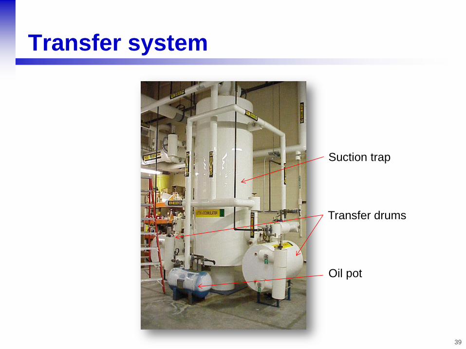
39
Transfer system
Suction trap
Transfer drums
Oil pot

Evaporative Condenser(s )
Equalize line
High Pressure Receiver
High pressure liquid
High pressure gas
Flooded evap 1
“Protected” suction
To HPR
Suction
trap
King valve
Flooded evap, n
Solenoid
valve
Flooded evaporator
Hand expansion
valve
Float
Transfer
Station
Dis
ch
arg
e lin
e
Gravity flooded recirculation system
Compressor(s)

Surg
e D
rum
Gravity flooded evaporator
Evaporator, liquid supply
Evaporator, vapor return

Evaporative Condenser Evaporative
Condenser
Eq
ua
lize
lin
e
Dry suction
High pressure liquid
High pressure gas
1
2
3
King valve
Pumped recirculator
4’ Overfed
evaporator(s)
4
T
4”’
Wet
return
3
Evaporative Condenser Evaporative
Condenser
Dis
ch
arg
e lin
e
Pumped liquid overfeed
Compressor(s)
High Pressure Receiver

Liquid overfeed system
Recirculator
Float column
Liquid refrigerant pumps
Pumped liquid
line

44
Liquid overfeed system components

45
• Lower evaporator temperatures
– Requires lower evaporator pressures
– Leading to increased compressor compression ratios
• Limitations of specific compression technologies
• Increased refrigerant discharge superheat
Two-stage compression systems

Equalize
line
Evaporative
Condenser(s)
Low
temperature
Evaporator(s)
Intercooler
Low
temperature
recirculator
Booster
Compressor(s)
High-Stage Compressor(s)
High Pressure Receiver
1 2
3
5
5’
6
5’’
4’
King valve
4’
4
7
Medium Temperature Recirculator/ Intercooler
T
DX Evap
Two-stage compression (two temperature level with two stages of liquid expansion)
10.4 psia or 8.8” Hg (~40F)
196 psia or 181 psig (~95F)
45 psia
(~17F)
𝐶𝑅𝐻𝑆 =196
45= 4.3: 1 𝐶𝑅𝐵 =
45
10.4= 4.3: 1

Evaporative Condenser Evaporative
Condenser
Eq
ua
lize
r li
ne
Dry suction
High Pressure Receiver
Hig
h p
ress
ure
liq
uid
High pressure gas
1
2
3
King valve (automatic)
3
Evaporative Condenser Evaporative
Condenser
Pumped
recirculator
4’
Overfed evaporator(s)
4
T 4”’
Wet
return
Compressor(s)
Suction
Trap
Compressor(s)
T T
DX evaporator
Flooded
Evaporator
What’s a “typical” system?
Transfer
Station
To HPR

52
QUESTIONS?

53
What did you learn?
1. Where does the vast majority of ammonia originate from?
2. Which of the following materials is not compatible with
ammonia: carbon steel, stainless steel, copper,
aluminum?
3. Ammonia is considered highly flammable:
True or False?
4. The “suction trap” is needed to prevent compressors from
ingesting liquid refrigerant:
True or False?
5. Which of the following is not an industrial ammonia
system configuration: direct-expansion, liquid underfeed,
gravity flooded, two-stage?