Åsgard Subsea Gas Compression - Nyheiterhniforum.no/cmsAdmin/uploads/statoil.pdf · 29.08.2011 ·...
30
Torstein Vinterstø Vice President Project Management ÅSC Åsgard Subsea Gas Compression
Transcript of Åsgard Subsea Gas Compression - Nyheiterhniforum.no/cmsAdmin/uploads/statoil.pdf · 29.08.2011 ·...

Torstein Vinterstø Vice President Project Management ÅSC
Åsgard Subsea Gas Compression

Åsgard
transport
to Kårstø
Åsgard
transport
Kristin
Åsgard A
Åsgard B
Åsgard C
Smørbukk
Smørbukk sør
Midgard

• Increased recovery
• Accelerated production
• Reduced CAPEX / phased
investment
• Operational flexibility
• Reduced OPEX
• HSE benefits
• Benefits increase with step-out &
water depth: an enabler
Why subsea processing?

Minimum Flow Challenge Surge Wave Instabilities
A minimum gas rate is required to:
Avoid dynamical instabilities in flow lines
Surge wave instabilities exceeds liquid handling capacity
Maintain continuous MEG return to Åsgard B
Avoid hydrate incidents

Increased Oil Recovery
~15 years
~ 280 million b.o.e.
Da
ily
pro
du
cti
on
MS
m3/d
Cu
mu
lativ
e p
rod
uc
tion
GS
m3
Year

Åsgard Subsea Compression
2 x 11,5 MW subsea compressors
40 km step out
Water depth 250-325 meters
Production 21 Mill Sm3/d
CAPEX ~15 billion NOK

Field Layout Today

Field Layout Future

Subsea Modules
From Midgard X
From Midgard Y
From Midgard Z
& Mikkel A & B
Compression Station
Weight: 4752 tons
Size: 74x45x26 m
Manifold station
Weight: 865 tons
Size: 34x27x15 m
To Åsgard B
To Hot-Tap on Y-101

Process Flow Diagram

Process Modules- Sizes and Dry Weights
Inlet Cooler
Weight: 235 tons
Size: 15 x 10 x 7 m
Scrubber
Weight: 210 tons
Size: 8 x 8 x 12 m
Compressor
Weight: 289 tons
Size: 11 x 9 x 10 m
Discharge Cooler
Weight: 107 tons
Size: 9 x 7 x 5 m
Pump
Weight: 45 tons
Size: 5 x 5 x 6 m
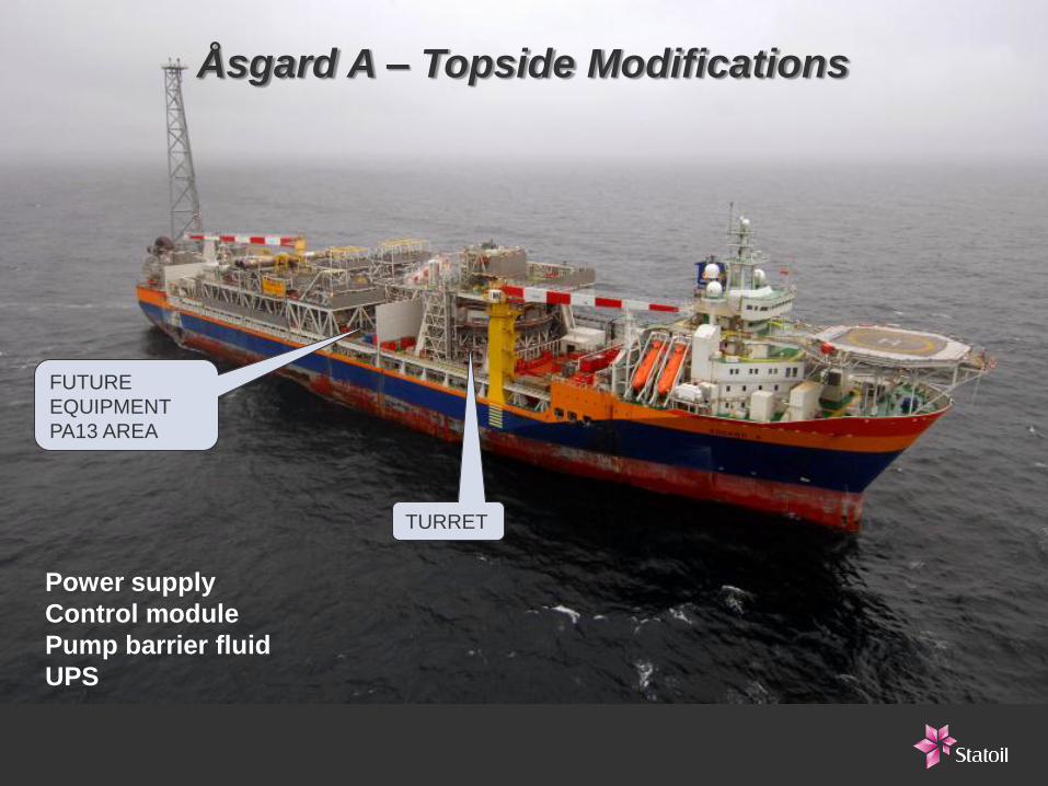
FUTURE
EQUIPMENT
PA13 AREA
TURRET
Åsgard A – Topside Modifications
Power supply
Control module
Pump barrier fluid
UPS

Cable routing
Ship
Power is generated from the two existing LM6000 Gas Turbines
Generator A LNOx DLE type 39 MW
Generator B HNOx Dual fuel type 37 MW
Power demand:
ÅSC 26 MW
ÅSG A 18-22 MW
High Voltage Power Supply
HVAC equipment:
Transformers
Variable speed drives for pump and
compressors
Switchboards
Cooling & HVAC equipment

The shell of the canister
can be sliced down for
ease of access and
maintenance
Åsgard A Swivel Project
High voltage swivel element:
• 2 x 3 ph lines; Um = 24 kV, Im = 675 A
• 2 x 3 ph lines; Um = 52 kV, Im = 675 A
• Separate earth ring
Installed summer 2011

Umbilical System
Åsgard A
SCSt
Åsgard B
Static part ~42km
Power umbilical
Power cable
Dynamic part < 1500m
Fibre link
Combined umbilical
Umbilical
Compressor Power
Pump Power
Control Power
Pump Barrier Fluid
Fibre Optic
Cable splice

Technology Qualification
Scrubber
Cooler
Active Magnetic
Bearing Control
Power Cable Subsea Transformer HV Connectors and Penetrators Hot-Tap
All Electric Subsea Control System
Initiated 2007
Comprehensive Scope
Maturing Competitive Vendors
Motor and Compressor


Qualification of Subsea Compressor at K-lab
Technology Qualification Program
World’s first large scale test loop for subsea compressors
built 2007-2008
Qualification program initiated at K-lab 2008
M33 compressor qualified 2009 after 3150 running hours
Qualification of long- step-out, high voltage, high frequency
power supply by use of cable simulator 2009-2010
Testing with hydrocarbon gas, condensate, and water/MEG
Liquid injection up to 30 weight %
Several design improvements during qualification
R&V testing 2010-2011 on improved design
K-lab
K-lab

1
9
-
Classification: Internal 2011-08-29
Building New Test Facility K-lab

New Test Facility K-lab
Testing of Pilot and Delivery Compressors
K-lab modification 2011-2013
Shallow water test pit
11,5 MW compressor shaft power
17 million Sm3/d flow rate hydrocarbon gas
Condensate and water/MEG injection
Submerged test of pilot compressor 2013
Submerged test of delivery units 2014

Qualification and FUT/SIT
Control system
Qualification of components according to
ISO 13628 and TR 1233
MBC system
Electrical actuators
Compressor
Motor size verification
Marinisation
HV penetrator
Functional Unit Testing (FUT)
Pump - Tranby
Control system – Aberdeen
Compressor – K-lab
System Integration Test (SIT)
Trains - Egersund
Syste
m C
om
ple
xity

Installation and Intervention
Initial Installation:
• Modularised by construction vessel
Options for Intervention:
• Construction vessel with over the side
handling system
• New build vessel with large moonpool

The Intervention Challenge
• Requirement for year round
intervention (Hs 4.5)
• Module size and weight
15x12x12m
~400T
• Handling subsea processing
HC, N2, MEG

Intervention with SHS
North Sea Giant
• Built in 2011
• World largest Construction
vessel in its class
• DP3 capabilities
• Large deck space (2900 m2)
• 400 Tons crane
• Voith Schneider Propulsion
Special Handling System (SHS)
• Fabrication of SHS for initial installation modules
• Dynamic analysis and tests to ensure sufficient strength
• Tower dimensions: 17x20x32m (w,d,h) TBC
• Free lift height: 17,5m (vertical, over deck) TBC
• Pallet size: min.13,5x10m TBC
• HPU skid/container: 8x2,5x3m (each) TBC

Vessel vs. Subsea Technology Steps
Gullfaks
TOGI Statfjord sat
Åsgard
Ormen
Lange /
Snøhvit Tordis SSBI
Tyrihans
SRSWI
Subsea Compression
Subsea Factory •Normand Mjolne
•Viking Poseidon
•Far Saga
•Edda Fauna
Seven Viking
Subsea Processing
Intervention Vessel

Typical ÅSC SPI service functionality:
26 -
• Integrated large and heavy module handling system, i.e. 400 T in 4,5 m Hs,
• Accommodate for modules up to the size of 15 x 12 metres and height up to 12 metres
• Hydrocarbon venting system
• Chemical tanks and pumping system for N2 and MEG
Examples of monohull intervention solutions

Oil storage
Gas compression
Gas, oil, produced
water separation
Power distribution
and control
Manifold
Sea water injection
template with pumping
Produced water
injection template
Production
template Produced water
injection pump Production
template
ROV
intervention
Oil pump
Oil export
Gas export
The Statoil Subsea Factory™

Critical path – CCS3
Classificati
on: Internal
2012-08-24 2
8
Main Milestones
Topside
Modifications
Subsea
Compression System
Pipeline and
Marine Operations
D E S C R I P T I O N
Train 1&2
2011 2012 2013 2014
PDO Submittal
Comm.
SCMS/SCSt
#1EPC
DG4
Sta
rt-up
Milestone Engineering Fabrication/Testing Offshore activities
Pipeline Components
Pow er Cables and Umbilicals
DWHot Tap Development
Shut dow nModule lif t in
Hot Tap
PipelineComm.
Pilot
PDO Approval
DG3
#2
Engineering
Prep
Spools, Tie-in & Spools, Tie-in & RFO
SCSt
2015
MCPre-fab
Module
MC
Kårstø Shut-dow n
K-Lab mod.
First Gas
Run-in
RiserPull-in
SIT#1 SIT #2
FUT Pilot
FUT#2FUT#1
SCMS
System Comm.
Critical Path
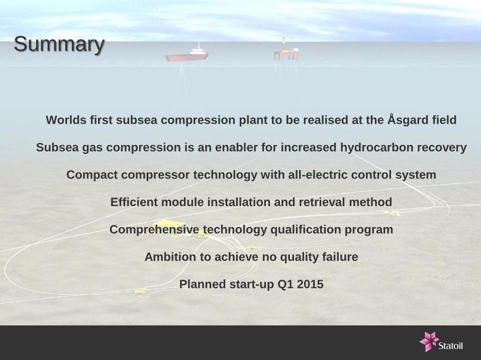
Summary
Worlds first subsea compression plant to be realised at the Åsgard field
Subsea gas compression is an enabler for increased hydrocarbon recovery
Compact compressor technology with all-electric control system
Efficient module installation and retrieval method
Comprehensive technology qualification program
Ambition to achieve no quality failure
Planned start-up Q1 2015

Thank you Torstein Vinterstø
Vice President Project Management
[email protected], tel: +47 99 520 865
www.statoil.com